


JWTS-10

This Manual is Bookmarked
Operating Instructions and Parts Manual
Table Saw
Model: JW TS -10
WMH TOOL GROUP
2420 Vantage Drive
Elgin, Illinois 60124 Part No. M-708100
Ph.: 800-274-6848 Revision B2 9/06
www.wmhtoolgroup.com Copyright © WMH Tool Group

WARRANTY AND SERVICE
WMH Tool Group, Inc., warrants every product it sells. If one of our tools needs service or repair, one of our
Authorized Service Centers located throughout the United States can give you quick service. In most cases, any of
these WMH Tool Group Authorized Service Centers can authorize warranty repair, assist you in obtaining parts, or
perform routine maintenance and major repair on your JET
your area call 1-800-274-6848.
MORE INFORMATION
WMH Tool Group is consistently adding new products to the line. For complete, up-to-date product information, check
with your local WMH Tool Group distributor, or visit jettools.com.
WARRANTY
JET products carry a limited warranty which varies in duration based upon the product (MW = Metalworking, WW =
Woodworking).
WHAT IS COVERED?
This warranty covers any defects in workmanship or materials subject to the exceptions stated below. Cutting tools,
abrasives and other consumables are excluded from warranty coverage.
WHO IS C OVERE D?
This warranty covers only the initial purchaser of the product.
WHAT IS THE PERIOD OF COVERAGE?
The general JET warranty lasts for the time period specified in the product literature of each product.
WHAT IS NOT COVERED?
Five Year Warranties do not cover woodworking (WW) products used for commercial, industrial or educational
purposes. Woodworking products with Five Year Warranties that are used for commercial, industrial or education
purposes revert to a One Year Warranty. This warranty does not cover defects due directly or indirectly to misuse,
abuse, negligence or accidents, normal wear-and-tear, improper repair or alterations, or lack of maintenance.
HOW TO GET SERVICE
The product or part must be returned for examination, postage prepaid, to a location designated by us. For the name
of the location nearest you, please call 1-800-274-6848.
You must provide proof of initial purchase date and an explanation of the complaint must accompany the
merchandise. If our inspection discloses a defect, we will repair or replace the product, or refund the purchase price,
at our option. We will return the repaired product or replacement at our expense unless it is determined by us that
there is no defect, or that the defect resulted from causes not within the scope of our warranty in which case we will,
at your direction, dispose of or return the product. In the event you choose to have the product returned, you will be
responsible for the shipping and handling costs of the return.
HOW STATE LAW APPLIES
This warranty gives you specific legal rights; you may also have other rights which vary from state to state.
LIMITATIONS ON THIS WARRANTY
WMH TOOL GROUP LIMITS ALL IMPLIED WARRANTIES TO THE PERIOD OF THE LIMITED WARRANTY FOR
EACH PRODUCT. EXCEPT AS STATED HEREIN, ANY IMPLIED WARRANTIES OR MERCHANTABILITY AND
FITNESS ARE EXCLUDED. SOME STATES DO NOT ALLOW LIMITATIONS ON HOW LONG THE IMPLIED
WARRANTY LASTS, SO THE ABOVE LIMITATION MAY NOT APPLY TO YOU.
WMH TOOL GROUP SHALL IN NO EVENT BE LIABLE FOR DEATH, INJURIES TO PERSONS OR PROPERTY,
OR FOR INCIDENTAL, CONTINGENT, SPECIAL, OR CONSEQUENTIAL DAMAGES ARISING FROM THE USE
OF OUR PRODUCTS. SOME STATES DO NOT ALLOW THE EXCLUSION OR LIMI TATION OF INCIDENTAL OR
CONSEQUENTIAL DAMAGES, SO THE ABOVE LIMITATION OR EXCLUSION MAY NOT APPLY TO YOU.
WMH Tool Group sells through distributors only. The specifications in WMH catalogs are given as ge neral information
and are not binding. Members of WMH Tool Group reserve the right to effect at any tim e, without prior notice, those
alterations to parts, fittings, and accessory equipment which they may deem necessary for any reason whatsoever.
® branded products are not sold in Canada by WMH Tool Group.
JET
® t ools. For the name of an Authorized Service Center in
2

Table of Contents
Table of Contents....................................................................................................................................3
Warnings ....................................................................................................................... ..........................4
Assembly...............................................................................................................................................11
Unpacking and Cleanup ..................................................................................................................... 11
Stand Assembly .................................................................................................................................11
Assembling the Saw to the Stand.......................................................................................................12
Blade Tilt Point er................................................................................................................................12
Handwheels .......................................................................................................................................13
Extens io n Wing s................................................................................................................................13
Rear Guide Rail..................................................................................................................................13
Front Guide Rail.................................................................................................................................14
Support Rod.......................................................................................................................................14
Switch Bracket...................................................................................................................................15
Extens io n Wing Adjustment................................................................................................................15
Blade Guard and Splitt er ....................................................................................................................15
Install ing /R e p la cing the B lad e .............................................................................................................16
Aligning the Blade Guard and Splitter.................................................................................................16
Table Insert........................................................................................................................................17
Rip Fence..........................................................................................................................................17
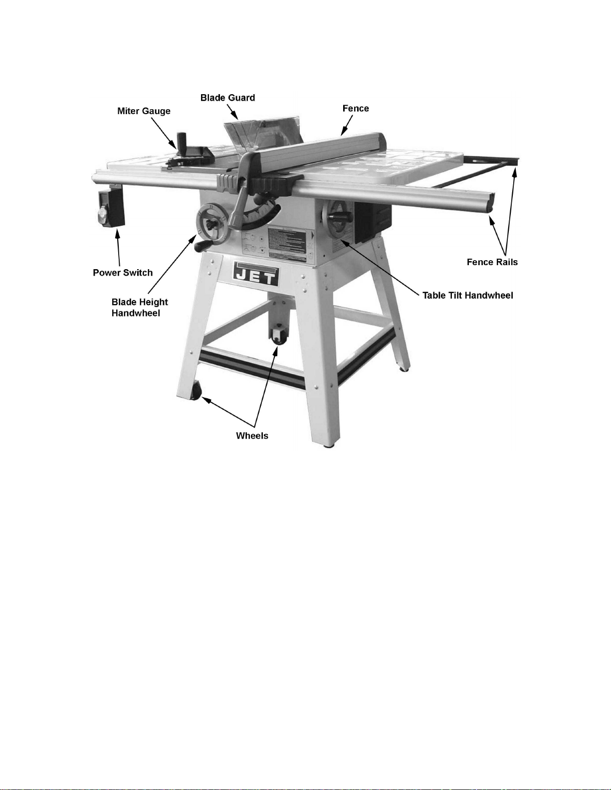
Miter Gauge...........................................................................................................................................18
Grounding Instructions...........................................................................................................................19
Electrical Connections........................................................................................................................19
Extension Cord Recommendations.....................................................................................................19
Blade Raising and Tilt Mechanism......................................................................................................20
Adjusting 45º and 90º Positive Stops..................................................................................................20
Operations.............................................................................................................................................21
Table Saws........................................................................................................................................21
Kickbacks.......................................................................................................................................21
Rip Sawi ng .....................................................................................................................................22
Resawing........................................................................................................................................23
Crosscutting....................................................................................................................................23
Align-a-rip ..........................................................................................................................................24
Bevel and Miter Operat ions................................................................................................................24
Safety Devices.......................................................................................................................................25
Feather Board....................................................................................................................................25
Filler Piece.........................................................................................................................................26
Push Stick & Push Bl ock ....................................................................................................................26
Maintenance..........................................................................................................................................27
Cleaning.............................................................................................................................................27
Lubrication .........................................................................................................................................27
Miscellaneous ....................................................................................................................................27
Troubleshooting.....................................................................................................................................28
Parts......................................................................................................................................................29
Wiring Di agram ................................................................................................................. .....................37
Ordering Replacement Parts..................................................................................................................38
3

Warnings
1. Read and understand the entire owners manual bef or e attempti ng assem bly or operation.
2. Read and understand the warnings po sted on the m achine and i n thi s manual. Failur e to comply wit h
all of these warnings m ay cause seriou s i njury.
3. Replace the warning labels if they become obscured or removed.
4. This Tabl e Saw is designed and intended f or use by properly trained and ex peri enc ed per sonnel only.
If you are not familiar with the proper and safe operation of a Table Saw, do not use until proper
training and knowledge have been obtained.
5. Do not use this Table Saw for other than its intended use. If used for other purposes, WMH Tool
Group discl aims any real or implied warranty and holds itself harmless from any injury t hat may result
from that use.
6. Always wear approved saf ety glasses/face shi elds whil e using thi s Table Saw. Ever yday eyeglasses
only have impact resi stant lenses; they are not safety glasses.
7. Bef ore operating this Tabl e Saw, remove tie, rings, watches and other j ewelry, and roll sleeves up
past the elbows. Rem ove all loose cl othing and confi ne long hair. Non-sl ip foot wear or anti-ski d floor
strips are recommended. Do not wear gloves.
8. Always use the blade guard on all '' through- sawing'' oper ati ons. A t hrough-sa wing operati on i s one in
which the blade cuts completely through the workpiece.
9. Kickback oc c ur s when the workpiece is thrown towards the operator at a high rate of speed. If you do
not have a clear understanding of kickback and how it occurs, DO NOT operate this table saw!
10. Wear ear protectors (plugs or muffs) during ext ended peri ods of oper ation.
11. Some dust created by power sanding, sawing, grinding, drilling and other construction activities
contain chemi cals known to cause cancer , bir th defects or other r eproductiv e harm . Some examples
of these chemic als are:
• Lead from lead based paint.
• Crystalli ne sil ic a from bricks, cement and other m asonry pr oducts.
• Arsenic and chromium from chemically treated lumber.
12. Your risk of exposure varies, depending on how often you do this type of work. To reduce your
exposure to these chemicals, work in a well-ventilated area and work with approved safety
equipment, such as face or dust masks that are specifically designed to filter out microscopic
particles.
13. Do not operate this machine while tired or under the influence of drugs, alcohol or any medicati on.
14. M ak e c ertain the switch is in the OFF position before connecting the machine to the power supply.
15. M ak e c ertain the machine is properly grounded.
16. M ak e all machine adjustm ents or maintenance with the machine unplugged from the power source.
17. Remove adjusting keys and wrenches. Form a habit of checking to see that keys and adjusting
wrenches are removed from the machine before turning it on.
18. Keep safety guards in place at all times when the machi ne is in use. If removed for maintenance
purposes, use extreme caution and replace the guards immediately.
19. M ak e sure the Table Saw is firmly secured to the floor or bench before use.
20. Check damaged parts. Before further use of the machine, a guard or other part that is damaged
should be carefully checked to determine that it will operate properly and perform its intended
function. Check for alignment of moving part s, binding of moving parts, br eakage of parts, mounting
and any other condi ti ons that m ay affect its operati on. A guard or ot her part that i s damaged shoul d
be properly repaired or replaced.
4

Error! Objects canno t be created from editing field codes.
21. P r ov ide for adequate space surrounding work area and non-glare, overhead lighting.
22. K eep the floor around the m achi ne cl ean and free of scrap material, oil and grease.
23. K eep v isitors a safe distanc e from the work area. Keep children away.
24. M ak e y our workshop child proof with padlocks, master switches or by removing starter keys.
25. Giv e your work undivi ded attention. Looking ar ound, carryi ng on a conversation and “ horse-play” ar e
careless acts that can r esul t in serious injury.
26. M aintain a balanced st anc e at all times so that you do not fall into the blade or other moving par ts. Do
not overreach or use excessive force to perform any machine operation.
27. Use the ri ght t ool at the cor rect speed and feed r ate. Do not forc e a tool or attachment to do a job for
which it was not designed. T he ri ght tool will do the job better and safer.
28. Use recom mended accessories; i mproper accessories may be hazardous.
29. Maintain tools with care. Keep saw blades sharp and clean for the best and safest performance.
Follow instructions for lubricati ng and changing accessories.
30. Turn off the mac hine before cleaning. Use a brush or compressed air to remove chips or debri s — do
not use your hands.
31. Do not stand on the machine. Seri ous injury could occur if the machine ti ps over.
32. Never leave the mac hine running unattended. Turn the power off and do not leave the machine until it
comes to a complete stop.
33. Remove loose item s and unnecessary work pieces from the area before starting the machine.
Familiarize you rself with the following safety no ti ces used in this manual:
This means that if precautions are not heeded, it may result in minor injury and/or
possible machine damage.
This means that if precauti ons are not heeded, it may result in serious injury or possibly
even death.
5

The most common accident s among table saw users, acco rding to statist ics, can
be linked to kickback, the high-speed expulsion of material from the table that can strike the
operator. Kickback can also result in operator’s hands being pull ed into the blade.
Kickback Prevention
Tips to avoid the most common causes of
kickback:
• Make sure the blade splitter is always
aligned wit h the blade. A workpiece can bind
or stop the flow of the cut if the blade spl itt er
is misaligned and resul t in kickback.
• Use the blade spli tter during every cut. The
blade splitter maintains the kerf in the
workpiece, which will reduce the chance of
kickback.
• Never attempt fr eehand cut s. The workpiece
must be f ed perf ectly parall el with t he blade,
otherwise kickback will likely occur. Always
use the rip fence or crosscut fence to
support the workpi ec e.
• Make sure that the r ip fence is parallel with
the blade. If not, the c hanc es of ki c k bac k ar e
very high. Tak e the time t o check and adjust
the rip fence.
• Feed cuts through to completion. Anytime
you stop feeding a workpiece that is in the
middle of a cut, the chance of binding,
resulting in kickback, is greatly increased.
Pro tection Ti ps from
Kickback
Kickback can happen even if precautions are
taken to prevent it. Listed below are some tips to
protect you if kickback DOES occur:
• Stand to the side of the blade when cutting.
An ejected workpiece usual ly travel s directly
in front of the blade.
• Wear safety glasses or a face shield. Your
eyes and face are the most vul nerable part
of your body.
• Never plac e your hand behind the blade. If
kickback occurs, your hand will be pulled
into the blade.
• Use a push stic k to keep your hands far ther
away from the moving blade. If a kickback
occurs, the push stick will most likely take
the damage that your hand would have
received.
6
Features
Specifications
Model Number............................................................................................................................JWTS-10
Stock Num ber ................................................................................................................................ 708100
Blade Diameter.....................................................................................................................................10"
Arbor Diameter....................................................................................................................................5/8"
Maximum Depth of Cut.....................................................................................................................3-1/8"
Maximum Rip to Right of Blade .............................................................................................................30"
Maximum Rip to Left of Blade...............................................................................................................12"
Maximum Depth of Cut at 45° ...........................................................................................................2-1/8"
Table in Front of Blade at Maximum Cut (in) ....................................................................................10-1/2
Maximum Width of Dado..................................................................................................................13/16"
Maximum Diameter of Dado....................................................................................................................8"
Table Height...................................................................................................................................36-1/2"
Table Size (Cast Iron) with Extensions.........................................................................................27" x 44"
Table Size (Cast Ir on) without Extensions....................................................................................27" x 20"
Overall Dimensions (D x W x H)....................................................................................40" x 55-1/2" x 42"
Arbor Speed ............................................................................................................................. 3600 RPM
Motor................................................................................ 115/230V, 60Hz , 1Ph, 1-1/2HP, Prewired 115V
Net Weigh t......................................................................................................................................205 lbs
Gross Weight..................................................................................................................................214 l bs
The specifications in this manual are given as general inform ation and are not binding. WM H Tool Group
reserves the r ight to effect, at any time and without prior notice, changes or alterati ons to parts, fi ttings,
and accessory equipment deemed necessary for any reason whatsoever.
7

Definitions And Terminology
Arbor: Metal shaft that connects the drive
mechanism to the blade.
Bevel Edge Cut: Tilt of the saw arbor and blade
between 0° and 45° to perform an angled cutting
operation.
Blade Guard: Mechanism mounted over the
saw blade to prev ent accidental c ontact with the
cutting edge.
Crosscut: Sawing oper ation in which the mi ter
gauge is used to cut across the grain of the
workpiece.
Dado Blade: Blade(s) used f or cutting grooves
and rabbets.
Dado Cut: Fl at bottomed groov e in the face of
the workpiece made wit h a dado blade.
Featherboard: Device used to keep a board
against the rip fence or table that allows the
operator to keep hands away from the saw
blade.
Kerf: The resulting cut or gap made by a saw
blade.
Kickback: An event in which the workpiece is
lifted up and thrown back toward an operator,
caused when a work piece binds on the saw
blade or between the sa w blade and rip f ence
(or other fixed object). To minimize or prevent
injury from kickbacks, see the Operating
Instructions section.
Miter Gauge: A component that controls the
workpiece movement while performing a
crosscut of vari ous angl es.
Non-Through Cut: A sawing operation that
requires the rem oval of the blade guard spl itter,
resulting in a c ut that does not protrude through
the top of the workpiece (includes Dado and
rabbet cuts).
The blade guard and split ter must be re-installed
after performing a non-through cut to avoid
accidental contact with the saw blade during
operation.
Parallel: Position of the rip fence equal in
distance at every point to the side face of the
saw blade.
Perpendicular: 90° (right angl e) intersection or
position of the vertical and horizontal planes
such as the posi tion of the saw blade (v ertical)
to the table surfac e ( hori z ontal).
Push Board/Push St ick: A n instr ument used to
safely push the workpiece through the cutting
operation.
Rabbet: A cutting operation that creates an
L-shaped channel along the edge of the board.
Rip Cut: A cut made along the grain of the
workpiece.
Splitter: Metal pl ate to which t he blade guard i s
attached that maintains the kerf opening in the
workpiece when performing a cutting operation.
Standard Kerf: 1/8" gap made with a standard
blade.
Straightedge: A tool used to check that a
surface is flat or parallel.
Through Sawing: A sawing operation in which
the workpiece thickness is completely sawn
through. Proper blade height usually allows a
1/8" of the top of the blade t o extend above the
wood stock.
Read and understand the entire contents of this manual before attempting
assembly or operat io n! Failure to comply may cause serious injury!
8
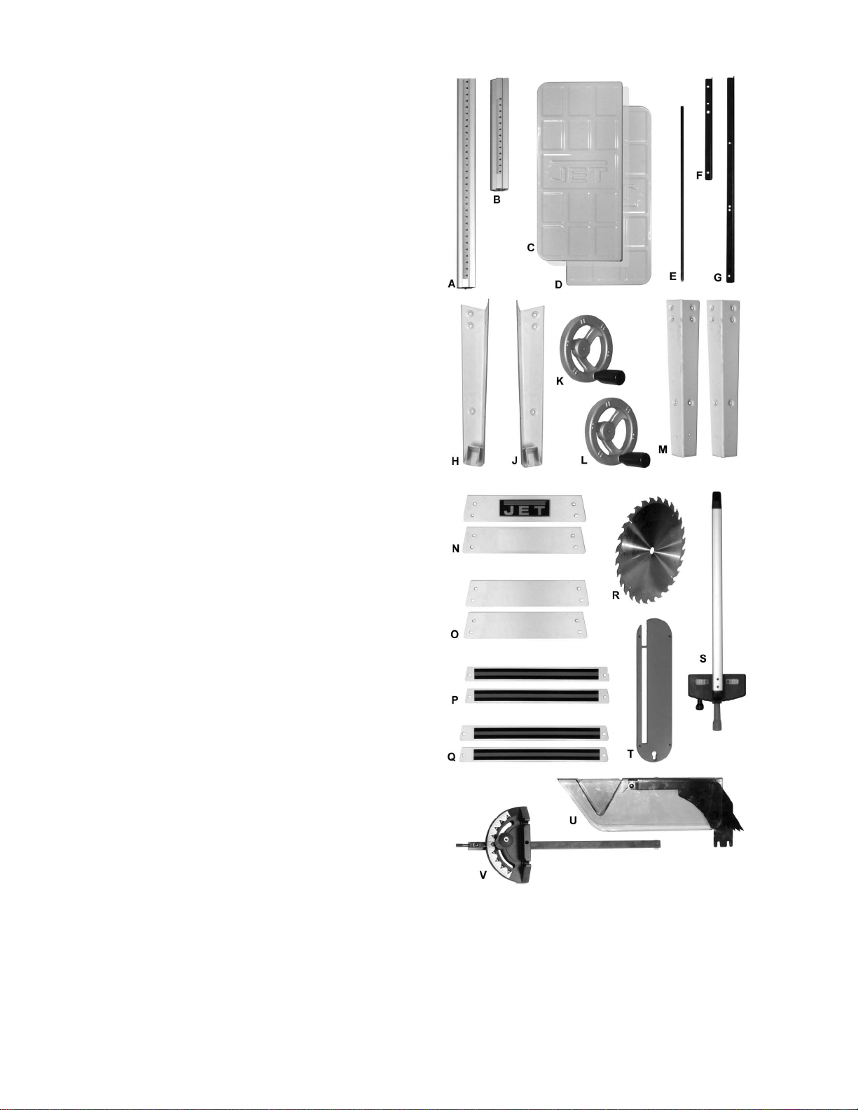
Shipping Contents
Carton Contents
1 ea Table Saw (not shown)
1 ea Front Rail – Long (A)
1 ea Front Rail – Short (B )
1 ea Extension Wing – Left ( C)
1 ea Extension Wing – Right (D)
1 ea Support Rod with mounting screw
and washer (E)
1 ea Rear Rail – Short (F)
1 ea Rear Rail – Long (G)
1 ea Left Leg – Rear (H)
1 ea Left Leg – Front (J)
1 ea Handwheel – Large Mounting Hole (K)
1 ea Handwheel – Small Mount ing Hole (L)
2 ea Right Leg (M)
2 ea Top Plate – Short (N)
2 ea Top Plate – Long (O)
2 ea Support Plate – Short ( P)
2 ea Support Plate – Long (Q)
1 ea Saw Blade (R)
1 ea Fence (S)
1 ea Table Insert (T )
1 ea Blade Guard Assembl y ( U)
1 ea Miter (V)
Carton Contents
9
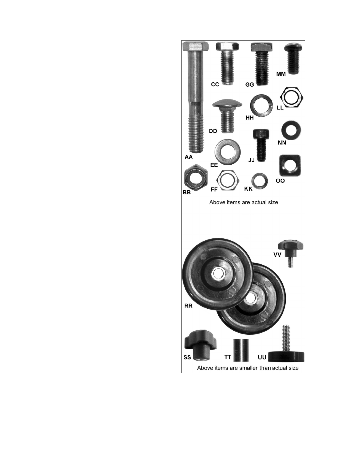
Hardware
The shipping carton includes two hardware bags
with parts f or assembli ng the JWTS-10 Tabl e Saw.
Hardware bag JWT S10-HP cont ains six packets of
parts and JWT S10-SHP contains three packets of
parts. If eit her bag is mi ssing the proper num ber of
packets, contact customer service (phone number
on cover and back pages).
Remove contents from all packets and sort.
Hardware contents can be identified by the
illustration to the right and quantities can be v erified
from the list below.
02 3/8”-16 x 2.5” Hex Cap Screw (AA)
02 3/8” Nylon Insert Lock Nut (B B )
18 M8x20 Hex Cap Screw (CC)
24 M8x12 Carriage Bolt (DD)
36 M8 Flat Washer (EE)
40 M8 Hex Nut (FF)
06 M8 Square Head Bolt (GG)
20 M8 Lock Washer (HH)
01 M5x12 Socket Head Cap Screw (JJ)
01 M5 Lock Washer ( K K)
04 5/16" Hex Nut (LL)
02 M6x10 Pan Head Screw (MM)
02 M6 Washer (NN)
02 M6 Square Nut (OO)
02 Wheel (RR)
01 Lock Knob for Front Handwheel (SS)
01 Bushing (TT)
02 Foot Pad (UU)
02 Lock Knob for Wheels (VV)
Tools Included for Assembly
2 Arbor/Blade G uar d B r acket Wrenc h
1 Hex Wrench (2.5mm)
1 12-14mm Open End Wrench
Addition al Tools Required
1 No. 1 and No. 2 Cross Point Screwdrivers
1 6"– 8" Adjustable W r enc h
1 Accurate Straight Edge (approximately 2 ft )
1 4mm Hex Wrench
1 13mm Box Wrench
Note: Use of sockets and ratchets will speed
assembly time but are not required.
Hardware Content s
10
Assembly
Read and understand all
assembly instructions before attempting
assembly! Failure to comply may cause
serious injury!
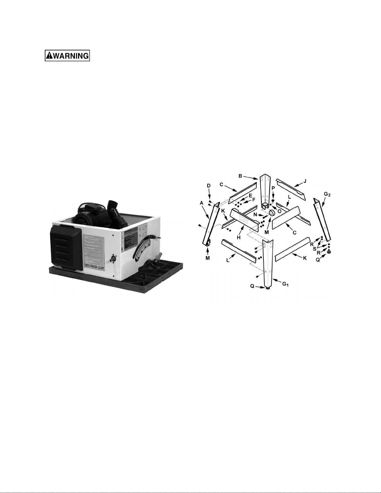
Unpacking and Cleanup
1. Remove all contents from the shipping carton.
Keep the saw tabl e upside down (Figure 1) and
place on a two-by-f our or similar piec e of wood
under the rear of the saw. This will help when
picking up the t able again. Do not discard t he
carton of packing material until the saw is
assembled and is runni ng satisfactoril y.
2. Inspect the contents for shipping damage.
Report damage, if any, to your distributor.
3. Compare the contents of the shipping carton
with the contents list in this manual. Report
shortages, if any, to y our distr ibutor.
2. Assemble the right legs (G
, G2) to the
1
remaining long top plate (C) in the same
manner.
3. Assemble the short top plate wit h the JET logo
(H) to the front stand legs (A, G
) using the
1
same combination of hardware as used to
attach the long top plates. Hand-tighten the
hardware only at this time.
4. Assemble the remaining short top plate (J) to
the rear stand legs (B, G
) in the same manner.
2
5. Assemble two long support plates (K) to the
inside of the left stand legs (A, B) and right
stand legs (G
, G2) respectively with the same
1
hardware. Hand-tighten only at this time.
Note: The long support plates have no cutouts.
Figure 1
Stand Assembly
Refer to Figure 2.
Tool required – 12mm wrench
Mounting Hardware – the stand (ex cluding wheels)
is assembled usi ng 24 eac h of t he following: M8x16
carriage bolts (D), M8 flat washers (E), and M8
hex nuts (F).
The legs consi st of one lef t front leg, one l eft rear
leg and two right legs. The left legs contain the
wheel mounti ng brackets and are not inter changeable. The ri ght legs are interchangeable. Refer to
Figure 2 for identification and orientation.
1. Assemble the front l eft and rear lef t legs (A, B )
to a long top plate (C) using the mounting
hardware listed above. Hand-tighten only at
this time. The long t op plates hav e no cutouts.
Note: For entire assembly place plates inside legs.
Figure 2
6. Assemble two short support plates (L) to the
inside of the front stand legs (A, G
stand legs (B, G
) respectively with the same
2
) and rear
1
hardware. Hand-tighten only at this time.
Note: The short support pl ates have cutouts.
7. Assemble two wheels (M) t o the left legs with
two 3/8”-16 x 2.5” hex cap screws (N) and two
3/8”-16 nylon insert lock nuts (O) and tighten
with two 13mm wrenches.
8. Place two wheel loc k k nobs ( P ) on the brackets
above the wheels.
9. Attach wheel pad ass emblies to the right l egs
(no wheels), each assembly consisting of one
threaded wheel pad (Q), two 5/16" hex nuts (R)
and two M8 flat washers (S).
11
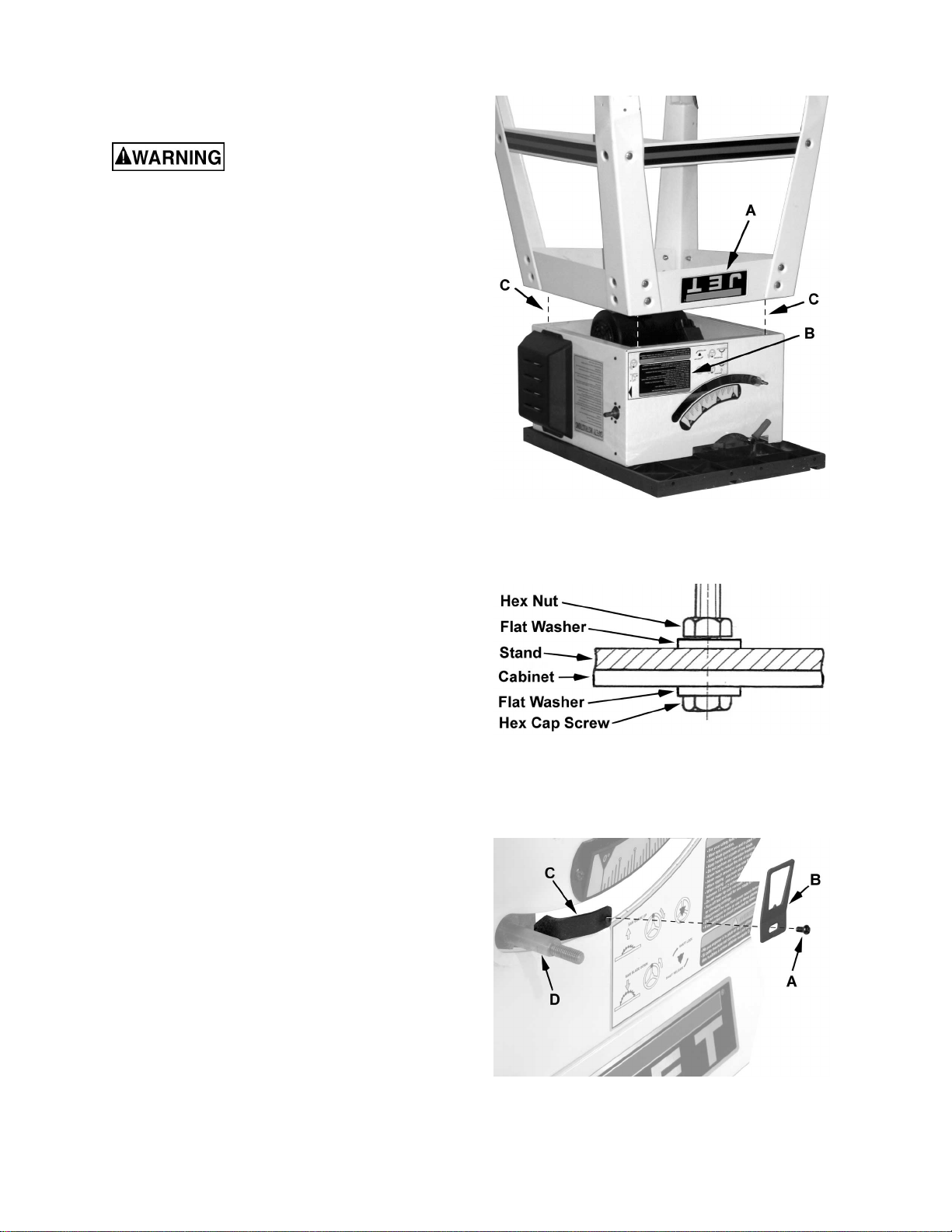
Assembling the Saw to the Stand
Do not plug the table saw into
the power source until all assembly has been
completed! Failure to comply may cause
serious injury!
1. Turn the stand upside down and place ont o the
table saw (Figure 3)
Note: The side with the JET logo (A) is the
front side of the stand and will be on the same
side as the Warning label ( B ) on the table saw.
Line up the holes i n the top pl ates of t he stand
with the holes i n the table saw (C) so t hat the
front of t he stand is f lush with the front of the
saw. The sides of the stand should also be
flush with the si des of the saw.
2. Attach the saw to the stand with four M8x20
hex cap screws, eight M8 flat washers and four
M8 hex nuts using Figure 4 as a guide. Ti ghten
the saw to the stand hardware f irmly.
3. Turn the table saw right side up. Make sure t he
saw is sitting level and with a 12mm wrench
tighten all stand har dware.
Blade Tilt Pointer
Figure 3
Figure 4
Referring to Fi gur e 5:
Secure the blade tilt pointer (B) on the front of the
saw onto the bracket (C) next to the shaft (D) with
an M4 screw (A) and tighten with a cross-point
screwdriver.
Figure 5
12
 Loading...