


INSTALLATION
INSTRUCTIONS
SMA/SMH 18/24
Version C
Single Zone Ductless Mini-Split System
A/C and Heat Pump
Heat Controller, Inc. • 1900 Wellworth Ave. • Jackson, MI 49203 • (517)787-2100 • www.heatcontroller.com

 1
1 
9

 11
11
12
12
Heat Controller, Inc. |
INSTALLATION INSTRUCTIONS |
SMA/SMH 18/24 |
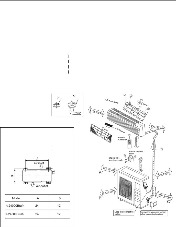
Installation Parts
Please install the accessories attached with unit correctly according to this installation manual.
Part No. |
Name of Part |
|
Quantity |
|
1 |
Installation Plate |
|
1 |
|
2 |
Anchor |
|
8 |
|
3 |
Mounting Screw A (ST3.9x25-C-H) |
8 |
||
4 |
Remote Controller |
|
1 |
|
5 |
Remote Controller Holder |
|
1 |
|
6 |
Mounting Screw B (ST2.9x10-C-H) |
2 |
||
|
|
Liquid side |
o 1/4" (<24,000 Btu/h) |
|
|
|
|
|
|
7 |
Refrigerant Pipe |
o 3/8" (≥24,000Btu/h) |
|
|
|
|
|
||
Gas Side |
o 1/2" (<24,000 Btu/h) |
|
||
|
|
|
||
|
|
|
|
|
|
|
o 5/8" (≥24,000 Btu/h) |
|
|
|
|
|
|
|
8 |
Seal* |
|
1 |
|
9 |
Drain Elbow* |
|
1 |
|
* See outdoor installation instructions
**Cautions on remote controller installation
•Keep the remote controller at least 3 feet from the nearest TV set or stereo equipment to advoid possible electronic interference.
•Do not leave the remote controller in a place exposed to direct sunlight or close to a heating source, such as a stove.
•Ensure that the positive and negative poles are correct when inserting batteries into the remote controller.
8 Seal |
9 |
Drain |
|
Elbow |
Anchoring the Outdoor Unit
•The outdoor unit should not be exposed to strong winds
•Anchor the outdoor unit with o5/16" anchor bolts
|
|
Remove the water receiver first |
U Bend example |
|
|
|
before connecting the piipes |
|
|
|
|
|
|
|
NOTICE: There should be at least two of the air flow inlets/ oulets labeled “A”, “B”, “C” above free from blockage.
2
SMA/SMH 18/24 |
INSTALLATION INSTRUCTIONS |
Heat Controller, Inc. |
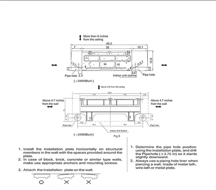
INDOOR UNIT INSTALLATION
1. Mounting Installation Plate and creating a Wall opening
Installation Plate and its measurements (inches):
Clearance:
Clearance: |
Clearance: |
5 inches or more |
5 inches or more |
Clearance:
Clearance: |
Clearance: |
1. Attach the installation plate |
2. Creating a wall opening |
|||
|
|
|
A. |
|
|
A. |
|
||
|
|
|
|
|
|
B. |
|
B. |
|
|
|
|
|
|
|
C. |
|
|
|
|
|
|
|
|
|
|
|
|
|
3

Heat Controller, Inc. |
INSTALLATION INSTRUCTIONS |
SMA/SMH 18/24 |
2. Line Set and Condensate Drain Line
1.Condenstate Drain
A.Run the drain hose sloping downward. DO NOT install the drain hose as illustrated below.
B.When extending the drain hose, insulate appropriately.
2. Line Set
Left rear piping
Right rear piping
A.
B. |
left-rear-hand piping, |
C.
•Connect the indoor unit first, then the outdoor unit. Bend and arrange the piping carefully.
•Do not allow the piping to loosen from the indoor unit during installation.
•Be sure not to let the drain hose slack.
•Insulate both pipes.
•Do not allow the power cable and control cable to be crossed.
4
 Loading...