


 Loading...
Hardware Reference Guide
NI-x100 Series
NetLinx® Integrated Controllers
(NI-2100, NI-3100, NI-4100)
|
|
|
|
NetLinx Integrated Controllers |
Last Revised: 1/9/2009 |
||
AMX Limited Warranty and Disclaimer
AMX warrants its products to be free of defects in material and workmanship under normal use for three (3) years from the date of purchase from AMX, with the following exceptions:
•Electroluminescent and LCD Control Panels are warranted for three (3) years, except for the display and touch overlay components that are warranted for a period of one (1) year.
•Disk drive mechanisms, pan/tilt heads, power supplies, and MX Series products are warranted for a period of one
(1) year.
•AMX Lighting products are guaranteed to switch on and off any load that is properly connected to our lighting products, as long as the AMX Lighting products are under warranty. AMX does guarantee the control of dimmable loads that are properly connected to our lighting products. The dimming performance or quality cannot be guaranteed due to the random combinations of dimmers, lamps and ballasts or transformers.
•Unless otherwise specified, OEM and custom products are warranted for a period of one (1) year.
•AMX Software is warranted for a period of ninety (90) days.
•Batteries and incandescent lamps are not covered under the warranty.
This warranty extends only to products purchased directly from AMX or an Authorized AMX Dealer.
All products returned to AMX require a Return Material Authorization (RMA) number. The RMA number is obtained from the AMX RMA Department. The RMA number must be clearly marked on the outside of each box. The RMA is valid for a 30-day period. After the 30-day period the RMA will be cancelled. Any shipments received not consistent with the RMA, or after the RMA is cancelled, will be refused. AMX is not responsible for products returned without a valid RMA number.
AMX is not liable for any damages caused by its products or for the failure of its products to perform. This includes any lost profits, lost savings, incidental damages, or consequential damages. AMX is not liable for any claim made by a third party or by an AMX Dealer for a third party.
This limitation of liability applies whether damages are sought, or a claim is made, under this warranty or as a tort claim (including negligence and strict product liability), a contract claim, or any other claim. This limitation of liability cannot be waived or amended by any person. This limitation of liability will be effective even if AMX or an authorized representative of AMX has been advised of the possibility of any such damages. This limitation of liability, however, will not apply to claims for personal injury.
Some states do not allow a limitation of how long an implied warranty last. Some states do not allow the limitation or exclusion of incidental or consequential damages for consumer products. In such states, the limitation or exclusion of the Limited Warranty may not apply. This Limited Warranty gives the owner specific legal rights. The owner may also have other rights that vary from state to state. The owner is advised to consult applicable state laws for full determination of rights.
EXCEPT AS EXPRESSLY SET FORTH IN THIS WARRANTY, AMX MAKES NO OTHER WARRANTIES, EXPRESSED OR IMPLIED, INCLUDING ANY IMPLIED WARRANTIES OF MERCHANTABILITY OR FITNESS FOR A PARTICULAR PURPOSE. AMX EXPRESSLY DISCLAIMS ALL WARRANTIES NOT STATED IN THIS LIMITED WARRANTY. ANY IMPLIED WARRANTIES THAT MAY BE IMPOSED BY LAW ARE LIMITED TO THE TERMS OF THIS LIMITED WARRANTY.

|
Table of Contents |
Table of Contents |
|
Introduction ........................................................................................................ |
1 |
NI-2100 Specifications .............................................................................................. |
2 |
NI-3100 Specifications .............................................................................................. |
5 |
NI-4100 Specifications .............................................................................................. |
8 |
Related Documents................................................................................................. |
11 |
Installation and Upgrading ............................................................................... |
13 |
Installing NetLinx Control Cards (NI-4100 Only) ..................................................... |
13 |
Setting the NetLinx Control Card Addresses (NI-4100 Only).................................. |
14 |
Device:Port:System (D:P:S)............................................................................................ |
14 |
Removing NetLinx Control Cards (NI-4100 Only) ................................................... |
15 |
Compact Flash Upgrades........................................................................................ |
15 |
Accessing The Internal Components On An Integrated Controller ............................... |
15 |
Installation of Compact Flash Upgrades........................................................................ |
16 |
Closing and Securing the Outer Housing ...................................................................... |
17 |
Installing Into An Equipment Rack .......................................................................... |
17 |
Connections and Wiring ................................................................................... |
19 |
Setting the Configuration DIP Switch (for the Program Port) ................................. |
19 |
Baud Rate Settings........................................................................................................ |
19 |
Program Run Disable (PRD) Mode................................................................................. |
19 |
Working With the Configuration DIP Switch ................................................................. |
20 |
Setting the CardFrame DIP Switch (NI-4100 Only) ................................................. |
20 |
Program Port Connections and Wiring ................................................................... |
20 |
Modes and Front Panel LED Blink Patterns ............................................................ |
21 |
Port Assignments and Functionality........................................................................ |
21 |
AXlink Port and LED ............................................................................................... |
22 |
Wiring Guidelines ................................................................................................... |
22 |
Wiring length guidelines ............................................................................................... |
22 |
Preparing Captive Wires ............................................................................................... |
23 |
Wiring a Power Connection........................................................................................... |
23 |
Using the 4-Pin Mini-Phoenix Connector For Data and Power ...................................... |
23 |
Using the 4-pin Mini-Phoenix Connector For Data With External Power ...................... |
24 |
DB9 Device Port: Connections and Wiring ............................................................. |
24 |
ICSNet Port: Connections and Wiring..................................................................... |
25 |
ICSHub OUT Port: Connections and Wiring ............................................................ |
26 |
Relay Port: Connections and Wiring ....................................................................... |
26 |
Relay Connections......................................................................................................... |
26 |
NI-2100, NI-3100, NI-4100 Hardware Reference Guide |
i |
|
|

Table of Contents |
|
Input/Output (I/O) Port: Connections and Wiring................................................... |
27 |
IR/Serial Port: Connections and Wiring................................................................... |
28 |
NetLinx Control Card Slot Connector (NI-4100 only).............................................. |
28 |
Ethernet/RJ-45 Port: Connections and Wiring ........................................................ |
29 |
Ethernet LEDs .............................................................................................................. |
29 |
Ethernet Ports Used By the Integrated Controller ........................................................ |
30 |
ii |
NI-2100, NI-3100, NI-4100 Hardware Reference Guide |
|
|

Introduction
Introduction
The X100-Series of NetLinx Integrated Master Controllers can both be programmed to control RS-232/422/485, Relay, IR/Serial, and Input/Output devices through the use of both the NetLinx programming language and the NetLinx Studio application version 2.x. Another key feature of this products is the ability to easily access the configuration switches without having to remove a cover plate.
NetLinx Integrated Master Controller Features
NI-2100 |
• 1 RS-232 Program port |
(FG2105-04) |
• 3 RS-232/RS-422/RS-485 ports |
|
|
|
• 4 IR/Serial Output ports |
|
• 4 Digital Input/Output ports |
|
• 4 Relays |
|
|
NI-2100 Kit |
• In addition to the options listed above, this Kit includes a pre-installed ICSNet daughter |
(FG2105-14) |
card (FG2105-10) |
|
|
NI-3100 |
• 1 RS-232 Program port |
(FG2105-05) |
• 7 RS-232/RS-422/RS-485 ports |
|
|
|
• 8 IR/Serial Output ports |
|
• 8 Digital Input/Output ports |
|
• 8 Relays |
|
|
NI-3100 Kit |
• In addition to the options listed above, this Kit includes a pre-installed ICSNet daughter |
(FG2105-15) |
card (FG2105-10) |
|
|
NI-4100 |
• Support for up to 4 NetLinx control cards (such as NXC-COM2, NXC-IRS4, etc.) |
(FG2105-06) |
• 1 ICSNet Hub port (part of the included pre-installed ICSNet card) |
|
|
|
• 1 RS-232 Program port |
|
• 2 ICSNet ports (part of the included pre-installed ICSNet card) |
|
• 7 RS-232/RS-422/RS-485 ports |
|
• 8 IR/Serial Output ports |
|
• 8 Digital Input/Output ports |
|
• 8 Relays |
|
|
References within this manual to NI X100-Series Controllers are used to describe the NI-2100/3100/4100 Integrated Controllers. When there is an overlap of information with other related NI Controllers, an X will be used to refer to both sets of units.
As an example, if a feature is shared by both the NI-4000 and the NI-4100 Controller, the term NI-4x00 Series is used.
These NI Controllers are shipped with Duet firmware and can not be downgraded to earlier Non-Duet firmware (< build 300).
These NI Controllers are Duet-compatible and can be upgraded via firmware. Duet is a dual-interpreter firmware platform from AMX which combines the proven reliability and power of NetLinx with the extensive capabilities of the Java®2 MicroEdition (J2ME) platform. Duet simplifies the programming of a system that includes the NI-900 and other third party devices by standardizing device and function definitions, defaulting touch panel button assignments, and controlling feedback methods. Dynamic Device Discovery makes integration even easier by automatically identifying and communicating with devices which support this new beaconing technology.
NI-2100, NI-3100, NI-4100 Hardware Reference Guide |
1 |
|
|
Introduction
These NI Controllers use a combination lithium battery and clock crystal package called a Timekeeper. Only one Timekeeper unit is installed within a given NI controller. The battery can be expected to have up to 3 years of usable life under very adverse conditions. Actual life is appreciably longer under normal operating conditions.
This calculation is based on storing the unit without power in 50° C (120° F) temperature until battery levels are no longer acceptable.
The part number for a replacement battery is 57-0032.
NI-2100 Specifications
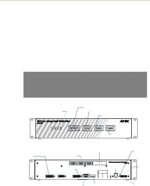
The NI-2100 (FIG. 1) provides support for 3 RS-232/RS-422/RS-485 Ports, 4 IR/Serial Output ports, 4 Digital Input/Output ports, and 4 Relays. The NI-2100 can be upgraded to provide
1 ICSHub and 2 ICSNet ports by either installing the optional ICSNet daughter card (FG2105-10) or purchasing this upgrade as an included feature of the NI-2100 Kit (FG2105-14).
FIG. 1 NI-2100 NetLinx Integrated Controller (front view)
RS-232/422/485 TX/RX LEDs (red/yellow)
Link/Active-Status-Output-Input |
|
Relay LEDs (red) |
|
IR/Serial LEDs (red)
 LINK/ACT INPUT
STATUS 
 OUTPUT
Front
1 |
2 |
3 |
TX RX TX RX TX RX |
||
RS - 232 / 422 / 485 |
||
1 |
2 |
3 |
4 |
1 |
2 |
3 |
4 |
1 |
2 |
3 |
4 |
|
RELAYS |
|
|
IR / SERIAL |
|
|
I / O |
|
|||
I/O LEDs (yellow)
ICSNet cover plate |
AXlink LED |
(green)
Relays |
RS-232/422/485 (Ports 1-3) |
|
(Port 4) |
||
|
PORT 3 |
PORT 2 |
PORT 1 |
AXlink |
IR/Serial (Ports 5-8) |
|
Ethernet |
port |
|
|
|
|
RS - 232 / 422 / 485 |
|
|
||
Pin |
(Ports 1-3) |
Function |
|
ETHERNET |
|
Function |
Pin |
|
10 / 100 |
||
1 |
RX- |
6 |
RX+ |
L/A |
SPD |
2 |
RXD |
7 |
RTS |
|
|
3 |
TXD |
8 |
CTS |
|
|
4 |
TX+ |
9 |
TX- |
|
|
5 |
GND |
|
|
|
|
|
|
|
|
|
|
|
|
|
|
|
|
|
|
|
|
Rear |
|
|
|
|
|
|
|
|
DIP |
|
|
|
|||
I/O (Port 9) |
Program |
|
|
||||||||||||
|
|
|
|
switch |
|
|
PWR |
||||||||
|
|
|
|
|
|||||||||||
FIG. 2 |
|
|
|
|
port |
|
ID Pushbutton |
|
|
|
|
||||
|
|
|
|
|
|
|
|
|
|
||||||
|
|
|
|
|
|
|
|
|
|
||||||
NI-2100 front and rear panel connectors and components |
|
|
|||||||||||||
2 |
NI-2100, NI-3100, NI-4100 Hardware Reference Guide |

Introduction
NI-2100 Specifications
Dimensions (HWD): |
• 3.47" x 17.00" x 3.47" (8.81 cm x 43.18 cm x 8.82 cm) |
|
• 2 rack units high |
|
|
Power Requirement: |
700 mA @ 12 VDC |
|
|
Memory: |
• 64 MB SDRAM |
|
• 1 MB Non-volatile (NV) SRAM |
|
|
Compact Flash: |
128 MB or more - Upgradeable (see Other AMX Equipment) |
|
Note: AMX may increase Flash size at any time in response to |
|
market availability (refer to product’s online catalog page for current Compact |
|
Flash size provided). |
|
|
Weight: |
4.50 lbs (2.04 kg) |
|
|
Enclosure: |
Metal with black matte finish |
|
|
Certifications: |
FCC Part 15 Class B, CE, and IEC 60950 |
|
|
Front Panel LEDs: |
|
|
|
• LINK/ACT: |
Green LED blinks when the Ethernet cables are connected and |
|
terminated correctly. Also blinks when receiving Ethernet data |
|
packets. |
|
|
• Status: |
Green LED blinks to indicate that the system is programmed and communi- |
|
cating properly. |
|
|
• Output: |
Red LED blinks when the Controller transmits data, sets channels On and |
|
Off, sends data strings, etc. |
|
|
• Input: |
Yellow LED blinks when the Controller receives data from button pushes, |
|
strings, commands, channel levels, etc. |
|
|
• RS-232/422/485: |
3 sets of red and yellow LEDs light to indicate that DB9 Ports 1 - 3 are trans- |
|
mitting or receiving RS-232, 422, or 485 data. |
|
|
• Relay: |
4 red LEDs light to indicate the relay channels 1 - 4 are active (closed). |
|
These LEDs reflect the state of the relay on Port 4. |
|
|
• IR/Serial: |
4 red LEDs light to indicate the IR/Serial channels 1 - 4 are |
|
transmitting control data on Ports 5 - 8. LED indictor for each IR port remains |
|
lit for the length of time that IR/Serial data is being generated. |
|
|
• I/O: |
4 yellow LEDs light when the I/O channels 1 - 4 are active. The LED for each |
|
I/O port reflects the state of that particular port. |
|
|
Rear Panel Components: |
|
• RS-232/422/485 (Ports 1 - 3): 3 RS-232/422/485 control ports using DB9 (male) connectors with XON/ XOFF (transmit on/transmit off), CTS/RTS (clear to send/ready to send), and 300-115,200 baud.
• ICSNet: |
2 RJ-45 connectors for ICSNet interface (provided by optional |
|
ICSNet daughter card). |
|
|
• ICSHub Out: |
RJ-45 connector provides data to a Hub connected to the Controller (pro- |
|
vided by optional ICSNet daughter card). |
|
|
• Relay (Port 4): |
• Four-channel single-pole single-throw relay ports |
|
• Each relay is independently controlled. |
|
• Supports up to 4 independent external relay devices |
|
• Channel range = 1-4 |
|
• Each relay can switch up to 24 VDC or 28 VAC @ 1 A |
|
8-pin 3.5 mm mini-Phoenix (female) connector provides relay termination |
|
|
• Digital I/O (Port 9): |
4-channel binary I/O port for contact closure with each input being capable of |
|
voltage sensing. Input format is software selectable with interactive power |
|
sensing for IR ports. |
NI-2100, NI-3100, NI-4100 Hardware Reference Guide |
3 |
|
|

Introduction
NI-2100 Specifications (Cont.)
Rear Panel Components (Cont.):
• IR/Serial |
4 IR/Serial control ports support high-frequency carriers of up to 1.142 MHz |
(Ports 5 - 8): |
with each output being capable of two electrical formats: IR or Serial. |
|
• 4 IR/Serial data signals can be generated simultaneously. |
|
• IR ports support data mode (at limited baud rates and wiring distances). |
|
|
• Program Port: |
RS-232 DB9 connector (male) can be connected to a DB9 port on a PC. This |
|
connector can be used with serial and NetLinx programming commands, as |
|
well as other DB9 capable devices, to both upload/download information from |
|
the NetLinx Studio program. |
|
|
• Configuration DIPSwitch: |
Sets the communication parameters for the Program port (see Baud Rate |
|
Settings). |
|
|
• ID Pushbutton: |
Sets the NetLinx ID (Device only) assignment for the device. |
|
|
• Ethernet Port: |
RJ-45 connector provides TCP/IP communication. This is an Auto MDI/MDI- |
|
X enabled port, which allows you to use either straight-through or crossover |
|
Ethernet cables. |
|
The Ethernet Port LEDs show communication activity, connection status, |
|
speeds, and mode information: |
|
• SPD (speed) - Yellow LED lights On when the connection speed is 100 |
|
Mbps and turns Off when the speed is 10 Mbps. |
|
• L/A (link/activity) - Green LED lights On when the Ethernet cables are |
|
connected and terminated correctly, and blinks when receiving Ethernet |
|
data packets. |
|
|
• AxLink Port: |
4-pin 3.5 mm mini-Phoenix (male) connector that provides data and power to |
|
external control devices. Green AXlink LED indicates the state of the AXlink |
|
port. |
|
|
• Power Port: |
2-pin 3.5 mm mini-Phoenix (male) connector. |
|
|
Included Accessories: |
• 2-pin 3.5 mm mini-Phoenix (female) PWR connector (41-5025) |
|
• 4-pin 3.5 mm mini-Phoenix (female) AXlink connector (41-5047) |
|
• 6-pin 3.5 mm mini-Phoenix female I/O connector (41-5063) |
|
• 8-pin 3.5 mm mini-Phoenix female Relay connector (41-5083) |
|
• Installation Kit (KA2105-01): |
|
- 8-pin Relay Common Strip |
|
- 4 rack mount screws |
|
- 4 washers |
|
• 2 CC-NIRC NetLinx IR Emitter Cables (FG10-000-11) |
|
• 2 removable rack ears (62-2105-07) |
|
|
Other AMX Equipment: |
• 2-pin 3.5 mm mini-Phoenix male connector (41-5026) |
|
• CSB Cable Support Bracket (FG517) |
|
• CC-COM Programming Port Cable (FG10-727) |
|
• CC-NSER IR/Serial cable (FG10-007-10) |
|
• ICSNet daughter card (FG2105-10) |
|
• NCK, NetLinx Connector Kit (FG2902) |
|
• STS, Serial To Screw Terminal (FG959) |
|
• Upgrade Compact Flash (factory programmed with firmware): |
|
NXA-CF2NI256M - 256 MB compact flash card (FG2116-47) |
|
NXA-CF2NI512M - 512 MB compact flash card (FG2116-48) |
|
NXA-CF2NI1G - 1 GB compact flash card (FG2116-49) |
|
|
4 |
NI-2100, NI-3100, NI-4100 Hardware Reference Guide |

Introduction
NI-3100 Specifications
The NI-3100 (FIG. 3) provides support for 7 RS-232/RS-422/RS-485 Ports, 8 IR/Serial Output ports, 8 Digital Input/Output ports, and 8 Relays.
The NI-3100 can be upgraded to provide one ICSHub and two ICSNet ports by either installing the optional ICSNet daughter card (FG2105-10) or purchasing this upgrade as an included feature of the NI3100 Kit (FG2105-15).
FIG. 3 NI-3100 NetLinx Integrated Controller (front view)
RS-232/422/485 TX/RX LEDs (red/yellow)
Link/Active-Status-Output-Input
Relay LEDs (red)
IR/Serial LEDs (red)
LINK/ACT |
INPUT |
1 |
2 |
3 |
4 |
5 |
6 |
7 |
STATUS |
OUTPUT |
TX RX TX |
RX TX |
RX TX |
RX TX |
RX TX RX |
TX RX |
|
|
|
RS - 232 / 422 / 485 |
|
|
||||
1 |
2 |
3 |
4 |
5 |
6 |
7 |
8 |
1 |
2 |
3 |
4 |
5 |
6 |
7 |
8 |
1 |
2 |
3 |
4 |
5 |
6 |
7 |
8 |
|
|
|
RELAYS |
|
|
|
|
|
|
IR / SERIAL |
|
|
|
|
|
|
I / O |
|
|
|
|||
I/O LEDs (yellow)
Front
AXlink LED
(green)
ICSNet cover plate
Rear |
RS-232/422/485 (Ports 1-7) |
IR/Serial (Ports 9-16)
AXlink port
Ethernet
RS - 232 / 422 / 485 (Ports 1-7)
Pin Function Pin Function
1 |
RX- |
6 |
RX+ |
2 |
RXD |
7 |
RTS |
3 |
TXD |
8 |
CTS |
4 |
TX+ |
9 |
TX- |
5 |
GND |
|
|
Relays |
|
I/O (Port 17) |
Program |
|
|
|
|
DIP |
|
|
|
|
(Port 8) |
|
|
port |
|
|
|
|
|
||||
|
|
|
|
switch |
|
|
PWR |
|||||
|
|
|
|
|
|
|
|
|
|
|||
FIG. 4 NI-3100 front and rear panel connectors and components |
ID Pushbutton |
|
|
|
||||||||
|
|
|
|
|||||||||
|
|
|
|
|||||||||
|
|
|
|
|
|
|
||||||
NI-2100, NI-3100, NI-4100 Hardware Reference Guide |
5 |
|
|

Introduction
NI-3100 Specifications
Dimensions (HWD): |
• 3.47" x 17.00" x 3.47" (8.81 cm x 43.18 cm x 8.82 cm) |
|
• 2 rack units high |
|
|
Power Requirement: |
900 mA @ 12 VDC |
|
|
Memory: |
• 64 MB SDRAM |
|
• 1 MB Non-volatile (NV) SRAM |
|
|
Compact Flash: |
128 MB or more |
|
• AMX may increase Flash size at any time in response to market availability |
|
• Upgradeable - see Other AMX Equipment |
|
|
Weight: |
4.55 lbs (2.06 kg) |
|
|
Enclosure: |
Metal with black matte finish |
|
|
Certifications: |
FCC Part 15 Class B, CE, and IEC 60950 |
|
|
Front Panel LEDs: |
|
|
|
• LINK/ACT: |
Green LED blinks when the Ethernet cables are connected and |
|
terminated correctly. Also blinks when receiving Ethernet data |
|
packets. |
|
|
• Status: |
Green LED blinks to indicate that the system is programmed and communi- |
|
cating properly. |
|
|
• Output: |
Red LED blinks when the Controller transmits data, sets channels On and |
|
Off, sends data strings, etc. |
|
|
• Input: |
Yellow LED blinks when the Controller receives data from button pushes, |
|
strings, commands, channel levels, etc. |
|
|
• RS-232/422/485: |
7 sets of red and yellow LEDs light to indicate that DB9 Ports 1 - 7 are trans- |
|
mitting or receiving RS-232, 422, or 485 data. |
|
|
• Relay: |
• Eight-channel single-pole single-throw relay ports |
|
• Each relay is independently controlled. |
|
• Supports up to 8 independent external relay devices |
|
• Channel range = 1-8 |
|
• Each relay can switch up to 24 VDC or 28 VAC @ 1 A |
|
Two 8-pin 3.5 mm mini-Phoenix (female) connectors provide relay |
|
termination |
|
|
• IR/Serial: |
8 red LEDs light to indicate the IR/Serial channels 1 - 8 are |
|
transmitting control data on Ports 9 - 16. LED indictor for each IR port |
|
remains lit for the length of time that IR/Serial data is being generated. |
|
|
• I/O: |
8 yellow LEDs light when the rear I/O channels 1 - 8 are active. The LED for |
|
each I/O port reflects the state of that particular port. |
|
|
Rear Panel Components: |
|
|
|
• RS-232/422/485 (Ports 1 - 7): |
7 RS-232/422/485 control ports using DB9 (male) connectors with XON/ |
|
XOFF (transmit on/transmit off), CTS/RTS (clear to send/ready to send), and |
|
300-115,200 baud. |
|
|
• ICSNet: |
2 RJ-45 connectors for ICSNet interface (provided by optional |
|
ICSNet daughter card). |
|
|
• ICSHub Out: |
RJ-45 connector provides data to a Hub connected to the Controller (pro- |
|
vided by optional ICSNet daughter card). |
|
|
• Relay (Port 8): |
8-channel single-pole single throw relay ports with each relay being indepen- |
|
dently controlled and supporting up to 8 independent |
|
external relay devices. |
|
|
• Digital I/O (Port 17): |
8-channel binary I/O port for contact closure with each input being capable of |
|
voltage sensing. Input format is software selectable with interactive power |
|
sensing for IR ports. |
|
|
6 |
NI-2100, NI-3100, NI-4100 Hardware Reference Guide |
Introduction
NI-3100 Specifications (Cont.)
Rear Panel Components (Cont.):
• IR/Serial (Ports 9 - 16): |
8 IR/Serial control ports support high-frequency carriers of up to 1.142 MHz |
|
with each output being capable of two electrical formats: IR or Serial. |
|
• 8 IR/Serial data signals can be generated simultaneously. |
|
• IR ports support data mode (at limited baud rates and wiring distances). |
|
|
• Program Port: |
RS-232 DB9 connector (male) can be connected to a DB9 port on a PC. This |
|
connector can be used with serial and NetLinx programming commands, as |
|
well as other DB9 capable devices, to both upload/download information from |
|
the NetLinx Studio program. |
|
|
• Configuration DIP |
Sets the communication parameters for the Program port (see Baud Rate |
Switch: |
Settings). |
|
|
• ID Pushbutton: |
Sets the NetLinx ID (Device only) assignment for the device. |
|
|
• Ethernet Port: |
RJ-45 connector provides TCP/IP communication. This is an Auto MDI/MDI-X |
|
enabled port, which allows you to use either straight-through or crossover |
|
Ethernet cables. |
|
The Ethernet Port LEDs show communication activity, connection status, |
|
speeds, and mode information: |
|
• SPD (speed) - Yellow LED lights On when the connection speed is 100 |
|
Mbps and turns Off when the speed is 10 Mbps. |
|
• L/A (link/activity) - Green LED lights On when the Ethernet cables are |
|
connected and terminated correctly, and blinks when receiving Ethernet |
|
data packets. |
|
|
• AxLink Port: |
4-pin 3.5 mm mini-Phoenix (male) connector that provides data and power to |
|
external control devices. Green AXlink LED indicates the state of the AXlink |
|
port. |
|
|
• Power Port: |
2-pin 3.5 mm mini-Phoenix (male) connector. |
|
|
Included Accessories: |
• 2-pin 3.5 mm mini-Phoenix (female) PWR connector (41-5025) |
|
• 4-pin 3.5 mm mini-Phoenix (female) AXlink connector (41-5047) |
|
• 10-pin 3.5 mm mini-Phoenix (female) I/O connector (41-5107) |
|
• Installation Kit (KA2105-01): |
|
- 8-pin Relay Common Strip |
|
- 4 rack mount screws |
|
- 4 washers |
|
• 2 8-pin 3.5 mm mini-Phoenix female Relay connectors (41-5083) |
|
• 2 CC-NIRC NetLinx IR Emitter Cables (FG10-000-11) |
|
• 2 removable rack ears (62-2105-07) |
|
|
Other AMX Equipment: |
• 2-pin 3.5 mm mini-Phoenix male connector (41-5026) |
|
• CSB Cable Support Bracket (FG517) |
|
• CC-NSER IR/Serial cables (FG10-007-10) |
|
• ICSNet daughter card (FG2105-10) |
|
• NCK, NetLinx Connector Kit (FG2902) |
|
• STS, Serial To Screw Terminal (FG959) |
|
• Upgrade Compact Flash (factory programmed with firmware): |
|
NXA-CF2NI256M - 256 MB compact flash card (FG2116-47) |
|
NXA-CF2NI512M - 512 MB compact flash card (FG2116-48) |
|
NXA-CF2NI1G - 1 GB compact flash card (FG2116-49) |
|
|
NI-2100, NI-3100, NI-4100 Hardware Reference Guide |
7 |
|
|
Loading...