


 Loading...
instruction manual
Axcent3 and
Axcent3 Pro
Integrated Axcess Controllers
Axcess Central Controllers
AMX Limited Warranty and Disclaimer
AMX Corporation warrants its products to be free of defects in material and workmanship under normal use for three
(3) years from the date of purchase from AMX Corporation, with the following exceptions:
•Electroluminescent and LCD Control Panels are warranted for three (3) years, except for the display and touch overlay components that are warranted for a period of one (1) year.
•Disk drive mechanisms, pan/tilt heads, power supplies, and MX Series products are warranted for a period of one
(1) year.
•AMX Lighting products are guaranteed to switch on and off any load that is properly connected to our lighting products, as long as the AMX Lighting products are under warranty. AMX Corporation does guarantee the control of dimmable loads that are properly connected to our lighting products. The dimming performance or quality cannot be guaranteed due to the random combinations of dimmers, lamps and ballasts or transformers.
•Unless otherwise specified, OEM and custom products are warranted for a period of one (1) year.
•AMX Software is warranted for a period of ninety (90) days.
•Batteries and incandescent lamps are not covered under the warranty.
This warranty extends only to products purchased directly from AMX Corporation or an Authorized AMX Dealer.
All products returned to AMX require a Return Material Authorization (RMA) number. The RMA number is obtained from the AMX RMA Department. The RMA number must be clearly marked on the outside of each box. The RMA is valid for a 30-day period. After the 30-day period the RMA will be cancelled. Any shipments received not consistent with the RMA, or after the RMA is cancelled, will be refused. AMX is not responsible for products returned without a valid RMA number.
AMX Corporation is not liable for any damages caused by its products or for the failure of its products to perform. This includes any lost profits, lost savings, incidental damages, or consequential damages. AMX Corporation is not liable for any claim made by a third party or by an AMX Dealer for a third party.
This limitation of liability applies whether damages are sought, or a claim is made, under this warranty or as a tort claim (including negligence and strict product liability), a contract claim, or any other claim. This limitation of liability cannot be waived or amended by any person. This limitation of liability will be effective even if AMX Corporation or an authorized representative of AMX Corporation has been advised of the possibility of any such damages. This limitation of liability, however, will not apply to claims for personal injury.
Some states do not allow a limitation of how long an implied warranty last. Some states do not allow the limitation or exclusion of incidental or consequential damages for consumer products. In such states, the limitation or exclusion of the Limited Warranty may not apply. This Limited Warranty gives the owner specific legal rights. The owner may also have other rights that vary from state to state. The owner is advised to consult applicable state laws for full determination of rights.
EXCEPT AS EXPRESSLY SET FORTH IN THIS WARRANTY, AMX CORPORATION MAKES NO OTHER WARRANTIES, EXPRESSED OR IMPLIED, INCLUDING ANY IMPLIED WARRANTIES OF MERCHANTABILITY OR FITNESS FOR A PARTICULAR PURPOSE. AMX CORPORATION EXPRESSLY DISCLAIMS ALL WARRANTIES NOT STATED IN THIS LIMITED WARRANTY. ANY IMPLIED WARRANTIES THAT MAY BE IMPOSED BY LAW ARE LIMITED TO THE TERMS OF THIS LIMITED WARRANTY.

Table of Contents
Table of Contents |
|
Product Information ................................................................................................. |
1 |
Specifications .................................................................................................................... |
1 |
Installation ................................................................................................................. |
3 |
Installing Axcess Control Cards (Axcent3 Pro Only) ......................................................... |
3 |
Installing the Axcent3 into an Equipment Rack ................................................................. |
3 |
Installing the AC-RK3 Rack Kit.......................................................................................... |
3 |
Installing the CSB Cable Support Bracket......................................................................... |
4 |
Wiring the Axcent3 ............................................................................................................ |
5 |
Preparing and connecting captive wires .................................................................................. |
5 |
RS-232/RS-422/RS-485 connections ...................................................................................... |
6 |
Using the AXlink connector for data and power ....................................................................... |
6 |
Using the AXlink connector for data with a separate 12 VDC power supply............................ |
6 |
Relay connections.................................................................................................................... |
7 |
IR/SERIAL/DATA connections ................................................................................................. |
7 |
Input/Output connections ......................................................................................................... |
7 |
Program connector (front and rear panels) .............................................................................. |
8 |
Axcess card slot connector (Axcent3 PRO only) ..................................................................... |
8 |
Axcess Programming ............................................................................................... |
9 |
Device and Channel Numbers .......................................................................................... |
9 |
Send_Commands for RS-232/422/485 Ports.................................................................... |
9 |
Send_String Escape Sequences for RS-232/422/485 Ports........................................... |
11 |
Send_Commands for IR/Serial/Data Ports...................................................................... |
11 |
Send_Commands for Input/Output Ports ........................................................................ |
16 |
Standard IR Function Order ............................................................................................ |
17 |
Program Port Commands................................................................................................ |
18 |
Xmodem Timing Commands........................................................................................... |
21 |
Setting PC-to-Axcess Program Communications, and a Controller’s Device Number in Termi- |
|
nal Emulator Mode ....................................................................................................... |
21 |
Setting PC to Axcess Program Communications and |
|
Setting Device Number in Normal Mode...................................................................... |
22 |
Axcess Master Mode....................................................................................................... |
22 |
Replacing the Lithium Batteries ............................................................................ |
25 |
Updating Firmware ................................................................................................. |
27 |
Configuration ................................................................................................................... |
27 |
Downloading Firmware.................................................................................................... |
27 |
Axcent3 and Axcent3 Pro Integrated Axcess Controllers |
i |
|
|
|
|

Table of Contents
|
ii |
Axcent3 and Axcent3 Pro Integrated Axcess Controllers |
|
|
|

Product Information
Product Information
The Axcent3 and Axcent3 Pro Integrated Axcess Controllers are multi-port Central Controllers that can be programmed to control RS-232/422/485, relay, IR/serial/data, and input/output devices. The Axcent3 Pro combines the multi-port functionality with 4 card slots that can be populated with Axcess Central Controller cards to accommodate system growth.
Specifications
The following table lists the specifications for the Axcent3 and Axcent3 Pro.
Specifications
Dimensions (HWD): |
|
Axcent3 |
3.47" x 17.0" x 3.0" (88.1 mm x 432 mm x 76.2 mm) |
Axcent3 Pro |
3.47" x 17.0" x 13.65" (88.1 mm x 432 mm x 356.8 mm) |
Weight: |
|
Axcent3 |
2.5 lbs (1.1 kg) |
Axcent3 Pro |
5.6 lbs (2.6 kg) without Axcess Control Cards |
Power Requirement: |
|
Axcent3 |
• 500 mA @ 12 VDC (all relays energized) |
Axcent3 Pro |
• 550 mA @ 12 VDC (without Axcess control cards) (all relays energized) |
Memory: |
• Volatile memory: 128Kbx16 (user-modifiable) |
|
• Non-volatile memory: 256Kbx16 (user-modifiable) |
|
|
Enclosure |
Metal with black matte finish |
|
|
Input buffer |
128 bytes |
|
|
Output buffer (AXlink) |
128 bytes |
|
|
Supported baud rates |
300, 600, 1200, 2400, 4800, 9600, 19200, 38400 |
|
|
Max. length of |
64 |
SEND_STRING to device |
|
|
|
Max. Length of data packets |
64 |
from device |
|
|
|
Front Panel Components: |
|
|
|
PROGRAM port |
DB-9 (male) connector for system programming |
|
|
Status indicators |
32 red LEDs showing port activity: |
|
• RS-232/422/485 - 6 receive LEDs and 6 transmit LEDs |
|
• Relay - 8 LEDs |
|
• IR/Serial/Data - 6 LEDs |
|
• I/O - 6 LEDs |
|
|
AXlink indicator |
Green LED shows AXlink data activity. Blink patterns include: |
|
• Off - No power, or the controller is not functioning properly |
|
• 1 blink per second - Normal operation. Device numbers match the |
|
programmed device numbers in the Axcess program. |
|
• 2 blinks per second - Device numbers do not match the Axcess program, |
|
a device is not present, or a device is not set to the right number. |
|
• 3 blinks per second - AXlink bus error. Check all AXlink bus connections. |
|
• Full On - Axcess program is not present and there is no AXlink activity |
|
|
Slots 1 - 4 |
4 Axcess Control Card slots (Axcent3 Pro only) |
RS-232 Range: |
50’ (15.24 m) max. |
|
|
Axcent3 and Axcent3 Pro Integrated Axcess Controllers |
1 |
|
|
|
|

Product Information
Specifications (Cont.) |
|
|
|
Rear Panel Components: |
|
|
|
RS-232/RS-422/RS-485 |
Six 9-pin (male) D-sub, RS-232/422/485 XON/XOFF, CTS/RTS, 300, 200 baud |
ports |
|
|
|
Status indicators |
32 red LEDs that show RS-232/422/485, relay, IR/Serial/Data, and I/O port |
|
activity. The LEDs light when data activity occurs on the associated ports. |
|
|
AXlink indicator |
Green LED showing power and AXlink data activity. |
|
|
AXlink/PWR connector |
4-pin connector for AXlink data and power, and 2-pin connector for external |
|
12 VDC power supply |
|
|
RELAYS connector |
Two 8-pin connectors, 750 mA, 28 VAC/24 VDC (normally open) |
|
|
IR/SERIAL/DATA |
12-pin (6 two-pins) male connector that supports IR, IR/Serial or one-way data |
connectors |
communication (0 - 5 VDC levels only) |
|
|
Input/Output connectors |
8-pin connector, I/O 1 - 6, Common, +12 VDC power tap 200 mA, contact |
|
closure or TTL logic inputs |
|
|
PROGRAM port |
DB-9 (male) connector for system programming and diagnostics |
|
|
Slots 1 - 4 |
Four 16-pin connectors for Axcess Control Cards (Axcent3 Pro only) |
Included Accessories: |
• 4 CC-IRC emitters |
|
• Metal tab strip for commoning relays |
|
• Rack-mount brackets |
|
|
Optional Accessories: |
• 12 VDC power supply |
|
• CSB Cable Support Bracket |
|
• AC-RK3 Rack Kit |
|
• Axcess Control Cards (Axcent3 Pro only) |
|
2 |
Axcent3 and Axcent3 Pro Integrated Axcess Controllers |
|
|
|
Installation
Installation
Installing Axcess Control Cards (Axcent3 Pro Only)
To install Axcess Control Cards:
1.Discharge the static electricity from your body, by touching a grounded object.
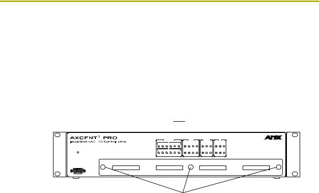
2.Remove the thumbscrews and faceplate from the front panel (FIG. 1).
Removable faceplate
|
|
|
RS-232 / 422 / 485 |
|
|
|
RELAYS |
|
|
IR / SERIAL |
|
|
I / O |
|
||
|
|
|
|
TX |
|
|
|
|
|
|
|
DATA |
|
|
|
|
|
|
|
|
|
|
|
|
|
|
|
|
|
|
|
|
|
|
1 |
2 |
3 |
4 |
5 |
6 |
1 |
2 |
3 |
4 |
1 |
2 |
3 |
1 |
2 |
3 |
AXlink |
|
|
|
RX |
|
|
|
|
|
|
|
|
|
|
|
|
1 |
2 |
3 |
4 |
5 |
6 |
5 |
6 |
7 |
8 |
4 |
5 |
6 |
4 |
5 |
6 |
|
PROGRAM
Thumbscrews
FIG. 1 Axcent3 Pro
3.Install up to 4 Axcess Control Cards component-side up into SLOT 1 - SLOT 4.
4.Replace the faceplate and secure with the thumbscrews.
Installing the Axcent3 into an Equipment Rack
Use the rack-mounting brackets supplied with each controller for equipment rack installations. Remove the mounting brackets for flat surface installations.
1.Discharge the static electricity from your body by touching a grounded object.
2.Place the controller into the equipment rack, and align the mounting bracket holes with the mounting holes on the equipment rack. Start the mounting screws on both sides of the controller and tighten.
3.Connect the data cables into the controller.
4.Connect the power cable to the AXLINK/PWR connector to power-up the controller.
Installing the AC-RK3 Rack Kit
Use the optional AC-RK3 Rack Kit for rear equipment rack rail installations or to place the controller 6 inches from the front/rear of the equipment rack. You need a Phillips-head screwdriver.
1.Discharge the static electricity from your body by touching a grounded object.
2.Remove the rack-mount brackets supplied with the controller.
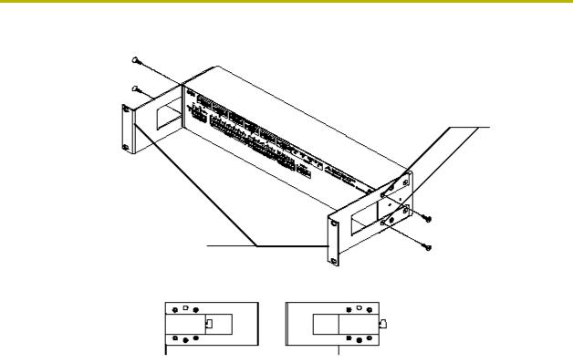
3.Install the AC-RK3 brackets with the supplied Phillips-head screws. Align the bracket holes with the mounting brackets on the equipment rack. Then, start the mounting screws on both sides of the controller and tighten (see FIG. 2).
Axcent3 and Axcent3 Pro Integrated Axcess Controllers |
3 |
|
|
|
|
Installation
Mounting screw holes
AC-RK3 Rack Kit mounting brackets
Mounting Configurations
Front |
Front |
FIG. 2 AC-RK3 Rack Kit mounting diagram
4.Connect the data cables into the controller.
5.Connect the power cable to the AXLINK/PWR connector to power-up the controller.
Installing the CSB Cable Support Bracket
Install the optional CSB Cable Support Bracket to secure the power and data cables connected to the controller. You can use the CSB with the supplied rack mounting brackets or optional AC-RK3. You need a Phillips-head screwdriver.
1.Discharge the static electricity from you body by touching a grounded object.
2.Disconnect all (if applicable) power and data cables from the controller.
3.Hold the controller in place, and remove the mounting hardware from the equipment rack. Then, carefully remove the controller from the rack and place it onto a flat surface.
4.Install the CSB, as shown in FIG. 3.
|
4 |
Axcent3 and Axcent3 Pro Integrated Axcess Controllers |
|
|
|

Installation
CSB Cable Support Bracket
Mounting screws
|
2", 4", 6" Mounting Configurations |
|
Mounting |
|
|
|
|
2" |
4" |
6" |
screws |
FIG. 3 CSB mounting diagram
5.Align the bracket holes with the mounting brackets on the equipment rack. Then, start the mounting screws on both sides of the controller and tighten.
6.Connect the data cables into the controller. Then, secure the data cables to the CSB.
7.Connect the power cable to the AXLINK/PWR connector to power-up the controller. Then, secure the cable to the CSB.
Wiring the Axcent3
Each connector you use to control external devices must be wired according to the information in
this subsection.
Preparing and connecting captive wires
1.Strip 0.25 inch of wire insulation off all wires.
2.Insert each wire into the appropriate opening on the connector according to the wiring diagrams and connector types.
3.Turn the flat-head screws clockwise to secure the wire in the connector. Do not over-torque the screw; doing so can bend the seating pin and damage the connector.
Axcent3 and Axcent3 Pro Integrated Axcess Controllers |
5 |
|
|
|
|
Installation
RS-232/RS-422/RS-485 connections
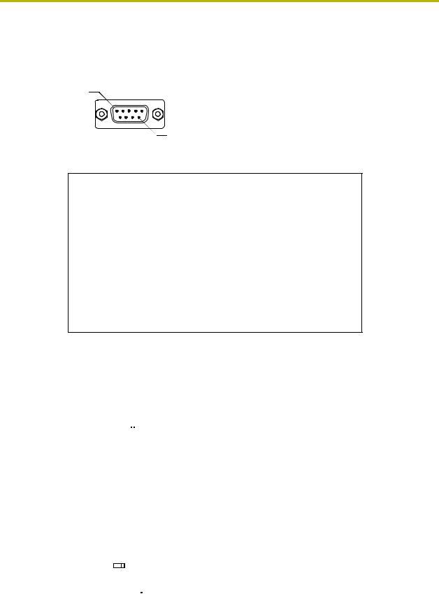
FIG. 4 shows the RS-232/RS-422/RS-485 DB-9 (male) connector pinouts. The table below lists the connector pins, signal types, and signal functions.
Pin 1
Pin 9
FIG. 4 RS-232/422/485 DB-9 (male) connector pinouts
DB-9 Pinouts |
Wiring and Baud Configurations |
||||
Pin |
Signal |
Function |
RS-232 |
RS-422 |
RS-485 |
|
|
|
|
|
|
1 |
RX- |
Receive data |
|
X |
X (strap to pin 9) |
|
|
|
|
|
|
2 |
RXD |
Receive data |
X |
|
|
|
|
|
|
|
|
3 |
TXD |
Transmit data |
X |
|
|
|
|
|
|
|
|
4 |
TX+ |
Transmit data |
|
X |
X (strap to pin 6) |
|
|
|
|
|
|
5 |
GND |
Signal ground |
X |
X |
|
|
|
|
|
|
|
6 |
RX+ |
Receive data |
|
X |
X (strap to pin 4) |
|
|
|
|
|
|
7 |
RTS |
Request to send |
X |
|
|
|
|
|
|
|
|
8 |
CTS |
Clear to send |
X |
|
|
|
|
|
|
|
|
9 |
TX- |
Transmit data |
|
X |
X (strap to pin 1) |
|
|
|
|
|
|
The X’s show where to terminate the wires on the DB-9 connector.
Using the AXlink connector for data and power
Connect the 4-pin AXlink connector to an external AXlink device, as shown in FIG. 5.
PWR+ |
|
|
|
|
|
|
|
|
|
|
|
|
|
|
|
PWR+ |
|
|
|
|
AXP/TX |
|
|
|
|
|
|
|
|
|
|
|
|
|
|
|
AXP |
|
External AXlink device |
||
AXM/RX |
|
|
|
|
|
|
|
|
|
|
|
|
|
|
|
AXM |
|
|||
|
|
|
|
|
|
|
|
|
|
|
|
|
|
|
|
|||||
GND- |
|
|
|
|
|
|
|
|
|
|
|
|
|
|
|
GND- |
|
|
||
|
|
|
|
|
|
|
|
|
|
|
|
|
|
|
||||||
|
|
|
|
|
|
|
|
|
|
|
|
|
|
|
|
|
|
|
|
|
AXlink/PWR connector |
|
|
|
|
|
|
|
|
|
|
|
|
||||||||
FIG. 5 AXlink/PWR data and power wiring diagram
Using the AXlink connector for data with a separate 12 VDC power supply
Connect the 4-pin AXlink connector to an external AXlink device; connect the 2-pin PWR connector to the separate 12 VDC power supply as shown in FIG. 6. Make sure to connect only the
|
|
|
|
|
|
|
|
|
|
|
PWR+ |
|
|
|
Local 12 VDC power supply |
|||||||||
|
|
|
|
|
|
|
|
|
|
|
|
|
|
|||||||||||
|
|
|
|
|
|
|
|
|
|
|
GND- |
|
|
|
|
for ext. AXlink device |
||||||||
PWR+ |
|
|
|
|
|
|
|
|
|
|
|
|
|
|
|
|
|
PWR+ |
|
|
|
|
||
AXP/TX |
|
|
|
|
|
|
|
|
|
|
|
|
|
|
|
|
|
AXP |
|
|
|
External AXlink device |
||
|
|
|
|
|
|
|
|
|
|
|
|
|
|
|
|
|
|
|
|
|||||
AXM/RX |
|
|
|
|
|
|
|
|
|
|
|
|
|
|
|
|
|
AXM |
|
|
|
|||
|
|
|
|
|
|
|
|
|
|
|
|
|
|
|
|
|
|
|
|
|
||||
GND- |
|
|
|
|
|
|
|
|
|
|
|
|
|
|
|
|
|
GND- |
|
|
|
|
||
|
|
|
|
|
|
|
|
|
|
|
|
|
|
|
|
|
|
|
|
|
||||
|
|
|
|
|
|
|
|
|
|
|
|
|
|
|
|
|
|
|
|
|
|
|
|
|
|
Axcent3 |
|
|
|
|
|||||||||||||||||||
FIG. 6 AXlink/PWR and optional 12 VDC power supply wiring diagram
|
6 |
Axcent3 and Axcent3 Pro Integrated Axcess Controllers |
|
|
|
Installation
GND wire on the AXlink/PWR connector when using a separate 12 VDC power supply. Do not connect the PWR wire to the AXlink connector’s PWR (+) opening.
Relay connections
Connect up to eight independent external relay devices to the 16-pin RELAYS connector. Use A for common and B for output. Each relay is isolated and normally open. A metal connector strip is also provided to common multiple relays.
8 7 6 5 4 3 2 1
B A B A B A B A B A B A B A B A
RELAYS 
FIG. 7 RELAY 16-pin connector
IR/SERIAL/DATA connections
Connect up to six IR, IR/Serial, and/or DATA (transmit only, 0 - 5 VDC levels only) devices to the 12-pin IR/SERIAL/DATA connector shown in FIG. 8. You can connect a CC-IRC Infrared Emitter, external serial device with a 2-pin captive-wire. You can also connect a data 0 - 5 VDC device.
6 |
5 |
4 |
3 |
|
|
2 |
1 |
||||||||||||||||||
|
|
|
|
|
|
|
|
|
|
|
|
|
|
|
|
|
|
|
|
|
|
|
|
|
|
IR / SERIAL / DATA
FIG. 8 IR/SERIAL/DATA 12-pin connector
Input/Output connections
Connect up to six Input/Output (I/O) devices to the INPUT/OUTPUT 8-pin connector, as shown in
INPUT/OUTPUT 8-pin (male) connector section on page 7. A contact closure between GND and an I/O port is detected as a PUSH. When used for a voltage input, the I/O port detects a low (0 - 1.5 VDC) as a PUSH, and a high signal (3.5 - 5 VDC) as a RELEASE. When used for an output, each I/O port acts as a switch to GND and is rated at 200 mA @ 12 VDC.
12V |
I / O 6 |
I / O 5 |
I / O 4 |
I / O 3 |
I / O 2 |
I / O 1 |
GND |
||
|
|
|
|||||||
 INPUT / OUTPUT
FIG. 9 INPUT/OUTPUT 8-pin (male) connector
+12V - 12 VDC power output for PCS Power Current Sensors, VSS2 Video Sync Sensors, or similar I/O-type equipment
I/O 1 - 6 - Six I/O ports
GND - Common ground shared with I/O ports 1 - 6
Axcent3 and Axcent3 Pro Integrated Axcess Controllers |
7 |
|
|
|
|
Loading...