

Page 1

Prestige 645R-A series
ADSL Router
User's Guide
Version 3.40
July 2003
Page 2

Prestige 645R-A Series User’s Guide
Copyright
Copyright © 2003 by ZyXEL Communications Corporation.
The contents of this publication may not be reproduced in any part or as a whole, transcribed, stored in a
retrieval system, translated into any language, or transmitted in any form or by any means, electronic,
mechanical, magnetic, optical, chemical, photocopying, manual, or otherwise, without the prior written
permission of ZyXEL Communications Corporation.
Published by ZyXEL Communications Corporation. All rights reserved.
Disclaimer
ZyXEL does not assume any liability arising out of the application or use of any products, or software
described herein. Neither does it convey any license under its patent rights nor the patent rights of others.
ZyXEL further reserves the right to make changes in any products described herein without notice. This
publication is subject to change without notice.
Trademarks
ZyNOS (ZyXEL Network Operating System) is a registered trademark of ZyXEL Communications, Inc.
Other trademarks mentioned in this publication are used for identification purposes only and may be
properties of their respective owners.
ii Copyright
Page 3

Prestige 645R-A Series User’s Guide
Federal Communications Commission
(FCC) Interference Statement
This device complies with Part 15 of FCC rules. Operation is subject to the following two conditions:
• This device may not cause harmful interference.
• This device must accept any interference received, including interference that may cause undesired
operations.
This equipment has been tested and found to comply with the limits for a Class B digital device pursuant to
Part 15 of the FCC Rules. These limits are designed to provide reasonable protection against harmful
interference in a commercial environment. This equipment generates, uses, and can radiate radio frequency
energy, and if not installed and used in accordance with the instructions, may cause harmful interference to
radio communications.
If this equipment does cause harmful interference to radio/television reception, which can be determined by
turning the equipment off and on, the user is encouraged to try to correct the interference by one or more of
the following measures:
1. Reorient or relocate the receiving antenna.
2. Increase the separation between the equipment and the receiver.
3. Connect the equipment into an outlet on a circuit different from that to which the receiver is connected.
4. Consult the dealer or an experienced radio/TV technician for help.
Notice 1
Changes or modifications not expressly approved by the party responsible for compliance could void the
user's authority to operate the equipment.
Certifications
Refer to the product page at www.zyxel.com
FCC Statement iii
.
Page 4

Prestige 645R-A Series User’s Guide
ZyXEL Limited Warranty
ZyXEL warrants to the original end user (purchaser) that this product is free from any defects in materials
or workmanship for a period of up to two years from the date of purchase. During the warranty period, and
upon proof of purchase, should the product have indications of failure due to faulty workmanship and/or
materials, ZyXEL will, at its discretion, repair or replace the defective products or components without
charge for either parts or labor, and to whatever extent it shall deem necessary to restore the product or
components to proper operating condition. Any replacement will consist of a new or re-manufactured
functionally equivalent product of equal value, and will be solely at the discretion of ZyXEL. This warranty
shall not apply if the product is modified, misused, tampered with, damaged by an act of God, or subjected
to abnormal working conditions.
Note
Repair or replacement, as provided under this warranty, is the exclusive remedy of the purchaser. This
warranty is in lieu of all other warranties, express or implied, including any implied warranty of
merchantability or fitness for a particular use or purpose. ZyXEL shall in no event be held liable for indirect
or consequential damages of any kind of character to the purchaser.
To obtain the services of this warranty, contact ZyXEL's Service Center for your Return Material
Authorization number (RMA). Products must be returned Postage Prepaid. It is recommended that the unit
be insured when shipped. Any returned products without proof of purchase or those with an out-dated
warranty will be repaired or replaced (at the discretion of ZyXEL) and the customer will be billed for parts
and labor. All repaired or replaced products will be shipped by ZyXEL to the corresponding return address,
Postage Paid. This warranty gives you specific legal rights, and you may also have other rights that vary
from country to country.
Safety Warnings
1. To reduce the risk of fire, use only No. 26 AWG or larger telephone wire.
2. Do not use this product near water, for example, in a wet basement or near a swimming pool.
3. Avoid using this product during an electrical storm. There may be a remote risk of electric shock from
lightening.
iv ZyXEL Warranty
Page 5
Prestige 645R-A Series User’s Guide
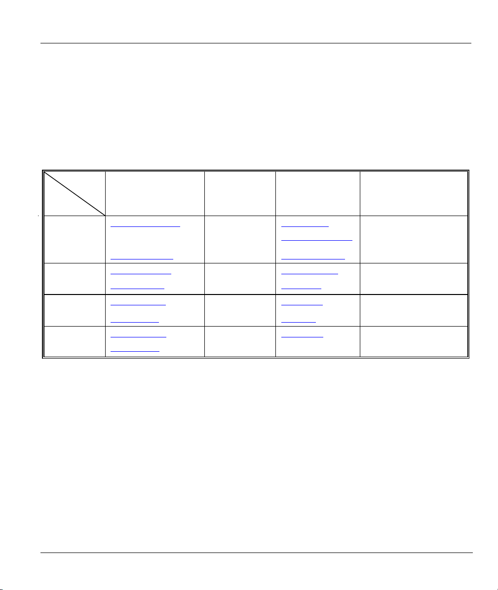
Customer Support
Please have the following information ready when you contact customer support.
• Product model and serial number.
• Warranty Information.
• Date that you received your device.
• Brief description of the problem and the steps you took to solve it.
METHOD
LOCATION
WORLDWIDE
AMERICA
E-MAIL
SUPPORT/SALES
support@zyxel.com.tw
sales@zyxel.com.tw
support@zyxel.com +1-800-255-4101 www.us.zyxel.com NORTH
sales@zyxel.com
support@zyxel.dk +45-3955-0700 www.zyxel.dk SCANDINAVIA
sales@zyxel.dk
support@zyxel.de +49-2405-6909-0 www.zyxel.de GERMANY
sales@zyxel.de
+886-3-578-2439 ftp.europe.zyxel.com
+1-714-632-0858 ftp.zyxel.com
+45-3955-0707 ftp.zyxel.dk
+49-2405-6909-99
TELEPHONE/FAX WEB SITE/ FTP SITE REGULAR MAIL
+886-3-578-3942 www.zyxel.com
www.europe.zyxel.com
ZyXEL Communications Corp.,
6 Innovation Road II, ScienceBased Industrial Park, Hsinchu
300, Taiwan.
ZyXEL Communications A/S,
Columbusvej 5, 2860 Soeborg,
Denmark.
ZyXEL Deutschland GmbH.
Adenauerstr. 20/A2 D-52146
Wuerselen, Germany
Customer Support v
Page 6

Prestige 645R-A Series User’s Guide
Table of Contents
ADSL Router.................................................................................................................................................... i
Copyright......................................................................................................................................................... ii
Federal Communications Commission (FCC) Interference Statement.....................................................iii
ZyXEL Limited Warranty ............................................................................................................................ iv
Customer Support........................................................................................................................................... v
Table of Contents ........................................................................................................................................... vi
List of Figures ...............................................................................................................................................xii
List of Tables ................................................................................................................................................ xvi
List of Charts .............................................................................................................................................xviii
Preface .......................................................................................................................................................... xix
Introduction to DSL.....................................................................................................................................xxi
Getting Started.................................................................................................................................................I
Chapter 1 Getting To Know Your Prestige ................................................................................................ 1-1
1.1 Introducing the Prestige 645R-A Series.....................................................................................1-1
1.2 Features of the Prestige..............................................................................................................1-1
1.3 Applications for the Prestige...................................................................................................... 1-3
1.3.1 Internet Access................................................................................................................... 1-3
1.3.2 LAN to LAN Application ..................................................................................................1-4
Chapter 2 Hardware Installation ...............................................................................................................2-1
2.1 Front Panel LEDs of the Prestige............................................................................................... 2-1
2.2 Rear Panel and Connections ......................................................................................................2-2
2.2.1 DSL Port ............................................................................................................................2-3
2.2.2 One Auto-crossover LAN 10/100M Port...........................................................................2-3
2.2.3 Using the Reset Button ......................................................................................................2-3
2.2.4 Making the Connections ....................................................................................................2-3
2.3 Additional Installation Requirements ........................................................................................2-4
2.4 Turning On Your Prestige.......................................................................................................... 2-4
Chapter 3 Introducing the Web Configurator ..........................................................................................3-1
3.1 Web Configurator Overview...................................................................................................... 3-1
3.2 Accessing the Prestige Web Configurator .................................................................................3-1
3.3 Navigating the Prestige Web Configurator................................................................................3-2
3.4 Configuring Password................................................................................................................3-3
3.5 Resetting the Prestige.................................................................................................................3-4
3.5.1 Using The Reset Button ..................................................................................................... 3-4
Chapter 4 Wizard Setup.............................................................................................................................. 4-1
4.1 Wizard Setup Introduction......................................................................................................... 4-1
4.2 Encapsulation.............................................................................................................................4-1
4.2.1 ENET ENCAP ...................................................................................................................4-1
4.2.2 PPP over Ethernet ..............................................................................................................4-1
vi Table of Contents
Page 7

Prestige 645R-A Series User’s Guide
4.2.3 PPPoA ................................................................................................................................4-1
4.2.4 RFC 1483 ...........................................................................................................................4-2
4.3 Multiplexing...............................................................................................................................4-2
4.3.1 VC-based Multiplexing......................................................................................................4-2
4.3.2 LLC-based Multiplexing ....................................................................................................4-2
4.4 VPI and VCI...............................................................................................................................4-2
4.5 Wizard Setup Configuration: First Screen .................................................................................4-2
4.6 IP Address and Subnet Mask .....................................................................................................4-4
4.7 IP Address Assignment ..............................................................................................................4-5
4.7.1 IP Assignment with PPPoA or PPPoE Encapsulation........................................................4-5
4.7.2 IP Assignment with RFC 1483 Encapsulation ...................................................................4-5
4.7.3 IP Assignment with ENET ENCAP Encapsulation ...........................................................4-5
4.7.4 Private IP Addresses...........................................................................................................4-6
4.8 Nailed-Up Connection (PPP) .....................................................................................................4-6
4.9 NAT ...........................................................................................................................................4-6
4.10 Wizard Setup Configuration: Second Screen.............................................................................4-6
4.10.1 PPPoE.................................................................................................................................4-7
4.10.2 RFC 1483 ...........................................................................................................................4-8
4.10.3 ENET ENCAP ...................................................................................................................4-9
4.10.4 PPPoA..............................................................................................................................4-10
4.11 Basic Setup Complete ..............................................................................................................4-12
LAN, NAT and Dynamic DNS ......................................................................................................................II
Chapter 5 LAN Setup ..................................................................................................................................5-1
5.1 LAN Overview...........................................................................................................................5-1
5.1.1 LANs, WANs and the Prestige...........................................................................................5-1
5.2 DNS Server Address ..................................................................................................................5-1
5.3 DNS Server Address Assignment ..............................................................................................5-2
5.4 LAN TCP/IP ..............................................................................................................................5-2
5.4.1 Factory LAN Defaults........................................................................................................5-2
5.4.2 IP Address and Subnet Mask..............................................................................................5-3
5.4.3 RIP Setup ...........................................................................................................................5-3
5.4.4 Multicast.............................................................................................................................5-3
5.5 Configuring LAN .......................................................................................................................5-4
Chapter 6 Network Address Translation (NAT)........................................................................................6-1
6.1 NAT Overview...........................................................................................................................6-1
6.1.1 NAT Definitions.................................................................................................................6-1
6.1.2 What NAT Does.................................................................................................................6-1
6.1.3 How NAT Works ...............................................................................................................6-2
6.1.4 NAT Application................................................................................................................6-3
6.1.5 NAT Mapping Types .........................................................................................................6-3
6.2 SUA (Single User Account) Versus NAT..................................................................................6-4
Table of Contents vii
Page 8

Prestige 645R-A Series User’s Guide
6.3 SUA Server................................................................................................................................ 6-5
6.3.1 Port Forwarding: Services and Port Numbers....................................................................6-5
6.3.2 Configuring Servers Behind SUA (Example).................................................................... 6-6
6.4 Selecting the NAT Mode ...........................................................................................................6-7
6.5 Configuring SUA Server............................................................................................................6-8
6.6 Configuring Address Mapping.................................................................................................6-10
6.7 Editing an Address Mapping Rule ...........................................................................................6-12
Chapter 7 Dynamic DNS Setup .................................................................................................................. 7-1
7.1 Dynamic DNS............................................................................................................................ 7-1
7.1.1 DYNDNS Wildcard...........................................................................................................7-1
7.2 Configuring Dynamic DNS .......................................................................................................7-1
Maintenance ..................................................................................................................................................III
Chapter 8 Maintenance...............................................................................................................................8-1
8.1 Maintenance Overview ..............................................................................................................8-1
8.2 System Status Screen ................................................................................................................. 8-1
8.2.1 System Statistics ................................................................................................................8-4
8.3 DHCP Table Screen...................................................................................................................8-6
8.4 Diagnostic Screens..................................................................................................................... 8-7
8.4.1 Diagnostic General Screen................................................................................................. 8-7
8.4.2 Diagnostic DSL Line Screen..............................................................................................8-9
8.5 Firmware Screen ...................................................................................................................... 8-10
SMT General Configuration........................................................................................................................IV
Chapter 9 Introducing the SMT................................................................................................................. 9-1
9.1 SMT Introduction ......................................................................................................................9-1
9.1.1 Procedure for SMT Configuration via Telnet ....................................................................9-1
9.1.2 Prestige SMT Menu Overview ..........................................................................................9-1
9.2 Navigating the SMT Interface....................................................................................................9-2
9.2.1 System Management Terminal Interface Summary...........................................................9-4
9.3 Changing the System Password ................................................................................................. 9-5
Chapter 10 General Setup.........................................................................................................................10-1
10.1 General Setup...........................................................................................................................10-1
10.2 Configuring Menu 1.................................................................................................................10-1
10.2.1 Configuring Dynamic DNS .............................................................................................10-3
Chapter 11 Ethernet Setup........................................................................................................................ 11-1
11.1 Ethernet Setup.......................................................................................................................... 11-1
11.1.1 General Ethernet Setup ....................................................................................................11-1
11.2 Protocol Dependent Ethernet Setup......................................................................................... 11-2
11.3 TCP/IP Ethernet Setup and DHCP...........................................................................................11-2
Chapter 12 Internet Access ....................................................................................................................... 12-1
12.1 Internet Access Overview ........................................................................................................12-1
12.2 IP Policies ................................................................................................................................12-1
viii Table of Contents
Page 9

Prestige 645R-A Series User’s Guide
12.3 IP Alias.....................................................................................................................................12-1
12.4 IP Alias Setup...........................................................................................................................12-2
12.5 Route IP Setup..........................................................................................................................12-4
12.6 Internet Access Configuration..................................................................................................12-5
Chapter 13 Remote Node Configuration..................................................................................................13-1
13.1 Remote Node Setup Overview.................................................................................................13-1
13.2 Remote Node Setup..................................................................................................................13-1
13.2.1 Remote Node Profile........................................................................................................13-1
13.2.2 Encapsulation and Multiplexing Scenarios ......................................................................13-2
13.2.3 Outgoing Authentication Protocol....................................................................................13-5
13.3 Metric .......................................................................................................................................13-5
13.4 Remote Node Network Layer Options.....................................................................................13-6
13.4.1 My WAN Addr Sample IP Addresses..............................................................................13-9
13.5 Remote Node Filter ..................................................................................................................13-9
13.5.1 Web Configurator Internet Security Filter Rules ...........................................................13-10
13.5.2 Web Configurator Filter Sets .........................................................................................13-11
13.6 Editing ATM Layer Options ..................................................................................................13-13
13.6.1 VC-based Multiplexing (non-PPP Encapsulation).........................................................13-13
13.6.2 LLC-based Multiplexing or PPP Encapsulation.............................................................13-13
Chapter 14 Static Route Setup..................................................................................................................14-1
14.1 IP Static Route Overview.........................................................................................................14-1
14.2 Configuring an IP static route ..................................................................................................14-2
Chapter 15 Bridging Setup........................................................................................................................15-1
15.1 Bridging Overview...................................................................................................................15-1
15.2 Bridge Ethernet Setup ..............................................................................................................15-1
15.2.1 Remote Node Bridging Setup...........................................................................................15-1
15.2.2 Bridge Static Route Setup ................................................................................................15-3
Chapter 16 Network Address Translation (NAT) ....................................................................................16-1
16.1 NAT Overview.........................................................................................................................16-1
16.1.1 SUA (Single User Account) Versus NAT........................................................................16-1
16.2 Applying NAT .........................................................................................................................16-1
16.3 NAT Setup ...............................................................................................................................16-3
16.3.1 Address Mapping Sets......................................................................................................16-4
16.4 Configuring a Server behind NAT ...........................................................................................16-9
16.5 General NAT Examples .........................................................................................................16-11
16.5.1 Example 1: Internet Access Only...................................................................................16-11
16.5.2 Example 2: Internet Access with an Inside Server .........................................................16-13
16.5.3 Example 3: Multiple Public IP Addresses With Inside Servers .....................................16-14
16.5.4 Example 4: NAT Unfriendly Application Programs......................................................16-17
SMT Advanced Management........................................................................................................................ V
Chapter 17 Filter Configuration...............................................................................................................17-1
Table of Contents ix
Page 10

Prestige 645R-A Series User’s Guide
17.1 About Filtering......................................................................................................................... 17-1
17.2 Configuring a Filter Set ...........................................................................................................17-4
17.2.1 Filter Rules Summary Menus ..........................................................................................17-6
17.3 Configuring a Filter Rule ......................................................................................................... 17-7
17.3.1 TCP/IP Filter Rule ........................................................................................................... 17-8
17.3.2 Generic Filter Rule.........................................................................................................17-12
17.4 Filter Types and NAT ............................................................................................................17-14
17.5 Example Filter........................................................................................................................17-14
17.6 Applying Filters and Factory Defaults...................................................................................17-17
17.6.1 Ethernet Traffic.............................................................................................................. 17-18
17.6.2 Remote Node Filters ......................................................................................................17-18
Chapter 18 SNMP Configuration.............................................................................................................18-1
18.1 SNMP Overview...................................................................................................................... 18-1
18.2 Supported MIBs.......................................................................................................................18-2
18.3 SNMP Configuration ...............................................................................................................18-2
18.4 SNMP Traps ............................................................................................................................18-4
Chapter 19 System Information and Diagnosis.......................................................................................19-1
19.1 System Maintenance Overview ............................................................................................... 19-1
19.2 System Status...........................................................................................................................19-1
19.3 System Information..................................................................................................................19-3
19.3.1 System Information..........................................................................................................19-3
19.3.2 Console Port Speed.......................................................................................................... 19-5
19.4 Log and Trace ..........................................................................................................................19-5
19.4.1 Viewing Error Log........................................................................................................... 19-5
19.4.2 Syslog and Accounting ....................................................................................................19-6
19.5 Diagnostic ................................................................................................................................ 19-8
19.6 Command Interpreter Mode.....................................................................................................19-9
Chapter 20 Firmware and Configuration File Maintenance .................................................................20-1
20.1 Filename Conventions .............................................................................................................20-1
20.2 Backup Configuration..............................................................................................................20-2
20.2.1 Backup Configuration......................................................................................................20-3
20.2.2 Using the FTP Command from the Command Line ........................................................20-3
20.2.3 Example of FTP Commands from the Command Line....................................................20-3
20.2.4 GUI-based FTP Clients....................................................................................................20-4
20.2.5 TFTP and FTP over WAN Will Not Work When ...........................................................20-4
20.2.6 Backup Configuration Using TFTP ................................................................................. 20-5
20.2.7 TFTP Command Example ...............................................................................................20-5
20.2.8 GUI-based TFTP Clients .................................................................................................20-5
20.3 Restore Configuration..............................................................................................................20-6
20.3.1 Restore Using FTP........................................................................................................... 20-6
20.3.2 Restore Using FTP Session Example...............................................................................20-8
x Table of Contents
Page 11

Prestige 645R-A Series User’s Guide
20.4 Uploading Firmware and Configuration Files..........................................................................20-8
20.4.1 Firmware File Upload ......................................................................................................20-8
20.4.2 Configuration File Upload ...............................................................................................20-9
20.4.3 FTP File Upload Command from the DOS Prompt Example..........................................20-9
20.4.4 FTP Session Example of Firmware File Upload............................................................20-10
20.4.5 TFTP File Upload ..........................................................................................................20-10
20.4.6 TFTP Upload Command Example .................................................................................20-11
Chapter 21 IP Policy Routing....................................................................................................................21-1
21.1 IP Policy Routing Overview ....................................................................................................21-1
21.2 Benefits of IP Policy Routing...................................................................................................21-1
21.3 Routing Policy..........................................................................................................................21-1
21.4 IP Routing Policy Setup...........................................................................................................21-2
21.5 Applying an IP Policy ..............................................................................................................21-5
21.5.1 Ethernet IP Policies..........................................................................................................21-5
21.6 IP Policy Routing Example ......................................................................................................21-7
Chapter 22 Call Scheduling.......................................................................................................................22-1
22.1 Call Scheduling Overview .......................................................................................................22-1
Appendices and Index.................................................................................................................................. VI
Appendix A Troubleshooting......................................................................................................................A-1
A.1 Using LEDs to Diagnose Problems...........................................................................................A-1
A.1.1 Power LED........................................................................................................................A-1
A.1.2 LAN LED..........................................................................................................................A-1
A.1.3 DSL LED ..........................................................................................................................A-2
A.2 Telnet ........................................................................................................................................A-2
A.3 Web Configurator......................................................................................................................A-3
A.4 Login Username and Password.................................................................................................A-3
A.5 LAN Interface ...........................................................................................................................A-4
A.6 WAN Interface..........................................................................................................................A-4
A.7 Internet Access..........................................................................................................................A-5
A.8 Remote Node Connection .........................................................................................................A-6
Appendix B IP Subnetting.......................................................................................................................... B-1
Appendix C PPPoE .....................................................................................................................................C-1
Appendix D Setting up Your Computer’s IP Address..............................................................................D-1
Appendix E Virtual Circuit Topology........................................................................................................E-1
Appendix F Splitters and Microfilters....................................................................................................... F-1
Appendix G Power Adaptor Specifications.............................................................................................. G-1
Appendix H Index ...................................................................................................................................... H-1
Table of Contents xi
Page 12

Prestige 645R-A Series User’s Guide
List of Figures
Figure 1-1 Internet Access Application...........................................................................................................1-4
Figure 1-2 LAN-to-LAN Application.............................................................................................................1-4
Figure 2-1 Front Panel ....................................................................................................................................2-1
Figure 2-2 Rear Panel .....................................................................................................................................2-2
Figure 3-1 Password Screen ...........................................................................................................................3-1
Figure 3-2 Web Configurator SITE MAP Screen ...........................................................................................3-2
Figure 3-3 Password .......................................................................................................................................3-3
Figure 4-1 Wizard Screen 1 ............................................................................................................................4-3
Figure 4-2 Internet Connection with PPPoE...................................................................................................4-7
Figure 4-3 Internet Connection with RFC 1483 .............................................................................................4-8
Figure 4-4 Internet Connection with ENET ENCAP......................................................................................4-9
Figure 4-5 Internet Connection with PPPoA ................................................................................................4-11
Figure 4-6 Wizard Screen 3 ..........................................................................................................................4-12
Figure 5-1 LAN and WAN IP Addresses........................................................................................................5-1
Figure 5-2 LAN ..............................................................................................................................................5-4
Figure 6-1 How NAT Works...........................................................................................................................6-2
Figure 6-2 NAT Application With IP Alias .....................................................................................................6-3
Figure 6-3 Multiple Servers Behind NAT Example........................................................................................6-7
Figure 6-4 NAT Mode.....................................................................................................................................6-7
Figure 6-5 Edit SUA/NAT Server Set.............................................................................................................6-9
Figure 6-6 Address Mapping Rules ..............................................................................................................6-11
Figure 6-7 Address Mapping Rule Edit ........................................................................................................6-12
Figure 7-1 DDNS............................................................................................................................................7-2
Figure 8-1 System Status ................................................................................................................................8-2
Figure 8-2 System Status: Show Statistics......................................................................................................8-4
Figure 8-3 DHCP Table ..................................................................................................................................8-6
Figure 8-4 Diagnostic .....................................................................................................................................8-7
Figure 8-5 Diagnostic General........................................................................................................................8-8
Figure 8-6 Diagnostic DSL Line.....................................................................................................................8-9
Figure 8-7 Firmware Upgrade ......................................................................................................................8-11
Figure 8-8 Network Temporarily Disconnected............................................................................................8-12
Figure 8-9 Error Message .............................................................................................................................8-12
Figure 9-1 Login Screen .................................................................................................................................9-1
Figure 9-2 Prestige 645R-A1 SMT Menu Overview......................................................................................9-2
Figure 9-3 SMT Main Menu...........................................................................................................................9-4
Figure 9-4 Menu 23 System Password ...........................................................................................................9-5
Figure 10-1 Menu 1 General Setup...............................................................................................................10-2
Figure 10-2 Menu 1.1 Configure Dynamic DNS..........................................................................................10-3
Figure 11-1 Menu 3 Ethernet Setup.............................................................................................................. 11-1
xii List of Figures
Page 13

Prestige 645R-A Series User’s Guide
Figure 11-2 Menu 3.1 General Ethernet Setup..............................................................................................11-1
Figure 11-3 Menu 3.2 TCP/IP and DHCP Ethernet Setup ............................................................................11-2
Figure 12-1 Physical Network ..................................................................................................................... 12-2
Figure 12-2 Partitioned Logical Networks................................................................................................... 12-2
Figure 12-3 Menu 3.2 TCP/IP and DHCP Setup.......................................................................................... 12-3
Figure 12-4 Menu 3.2.1 IP Alias Setup........................................................................................................ 12-3
Figure 12-5 Menu 1 General Setup.............................................................................................................. 12-4
Figure 12-6 Menu 4 Internet Access Setup .................................................................................................. 12-5
Figure 13-1 Menu 11 Remote Node Setup................................................................................................... 13-2
Figure 13-2 Menu 11.1 Remote Node Profile.............................................................................................. 13-3
Figure 13-3 Menu 11.3 Remote Node Network Layer Options................................................................... 13-7
Figure 13-4 Sample IP Addresses for a TCP/IP LAN-to-LAN Connection................................................. 13-9
Figure 13-5 Menu 11.5 Remote Node Filter (RFC 1483 or ENET Encapsulation) ................................... 13-10
Figure 13-6 Menu 11.5 Remote Node Filter (PPPoA or PPPoE Encapsulation)........................................ 13-10
Figure 13-7 Internet Security ......................................................................................................................13-11
Figure 13-8 Menu 21- Filer Set Configuration .......................................................................................... 13-12
Figure 13-9 Menu 21.11- WebSet 11 ......................................................................................................... 13-12
Figure 13-10 Menu 21.12- WebSet 12 ....................................................................................................... 13-12
Figure 13-11 Menu 11.6 for VC-based Multiplexing................................................................................. 13-13
Figure 13-12 Menu 11.6 for LLC-based Multiplexing or PPP Encapsulation ........................................... 13-14
Figure 14-1 Sample Static Routing Topology.............................................................................................. 14-1
Figure 14-2 Menu 12 Static Route Setup..................................................................................................... 14-2
Figure 14-3 Menu 12.1 IP Static Route Setup.............................................................................................. 14-2
Figure 14-4 Menu12.1.1 Edit IP Static Route.............................................................................................. 14-3
Figure 15-1 Menu 11.1 Remote Node Profile.............................................................................................. 15-2
Figure 15-2 Menu 11.3 Remote Node Network Layer Options................................................................... 15-2
Figure 15-3 Menu 12.3.1 Edit Bridge Static Route...................................................................................... 15-3
Figure 16-1 Menu 4 Applying NAT for Internet Access.............................................................................. 16-2
Figure 16-2 Menu 11.3 Applying NAT to the Remote Node ....................................................................... 16-3
Figure 16-3 Menu 15 NAT Setup................................................................................................................. 16-4
Figure 16-4 Menu 15.1 Address Mapping Sets............................................................................................ 16-4
Figure 16-5 Menu 15.1.255 SUA Address Mapping Rules.......................................................................... 16-5
Figure 16-6 Menu 15.1.2.............................................................................................................................. 16-6
Figure 16-7 Menu 15.1.1.1 Editing/Configuring an Individual Rule in a Set.............................................. 16-8
Figure 16-8 Menu 15.2 NAT Server Setup................................................................................................... 16-9
Figure 16-9 Menu 15.2.1 NAT Server Setup.............................................................................................. 16-10
Figure 16-10 Multiple Servers Behind NAT Example ................................................................................16-11
Figure 16-11 NAT Example 1 .................................................................................................................... 16-12
Figure 16-12 Menu 4 Internet Access & NAT Example ............................................................................ 16-12
Figure 16-13 NAT Example 2 .................................................................................................................... 16-13
Figure 16-14 Menu 15.2.1 Specifying an Inside Server............................................................................. 16-13
List of Figures xiii
Page 14

Prestige 645R-A Series User’s Guide
Figure 16-15 NAT Example 3..................................................................................................................... 16-14
Figure 16-16 Example 3: Menu 11.3 .......................................................................................................... 16-15
Figure 16-17 Example 3: Menu 15.1.1.1 ....................................................................................................16-16
Figure 16-18 Example 3: Final Menu 15.1.1..............................................................................................16-16
Figure 16-19 NAT Example 4..................................................................................................................... 16-17
Figure 16-20 Example 4: Menu 15.1.1.1 Address Mapping Rule...............................................................16-18
Figure 16-21 Example 4: Menu 15.1.1 Address Mapping Rules ................................................................ 16-18
Figure 17-1 Outgoing Packet Filtering Process ............................................................................................ 17-2
Figure 17-2 Filter Rule Process ....................................................................................................................17-3
Figure 17-3 Menu 21 Filter Set Configuration .............................................................................................17-4
Figure 17-4 NetBIOS_WAN Filter Rules Summary.....................................................................................17-5
Figure 17-5 NetBIOS_LAN Filter Rules Summary......................................................................................17-5
Figure 17-6 TELNET_WAN Filter Rules Summary.....................................................................................17-5
Figure 17-7 PPPoE Filter Rules Summary ...................................................................................................17-6
Figure 17-8 FTP_WAN Filter Rules Summary.............................................................................................17-6
Figure 17-9 Menu 21.x.1 TCP/IP Filter Rule................................................................................................17-8
Figure 17-10 Executing an IP Filter............................................................................................................ 17-11
Figure 17-11 Menu 21.6.1 Generic Filter Rule ..........................................................................................17-12
Figure 17-12 Protocol and Device Filter Sets.............................................................................................17-14
Figure 17-13 Sample Telnet Filter ..............................................................................................................17-15
Figure 17-14 Menu 21.3.1 Sample Filter....................................................................................................17-16
Figure 17-15 Menu 21.3 Sample Filter Rules Summary ............................................................................17-17
Figure 17-16 Filtering Ethernet Traffic.......................................................................................................17-18
Figure 17-17 Filtering Remote Node Traffic ..............................................................................................17-19
Figure 18-1 SNMP Management Model.......................................................................................................18-1
Figure 18-2 Menu 22 SNMP Configuration .................................................................................................18-3
Figure 19-1 Menu 24 System Maintenance..................................................................................................19-1
Figure 19-2 Menu 24.1 System Maintenance : Status ..................................................................................19-2
Figure 19-3 Menu 24.2 System Information and Console Port Speed..........................................................19-3
Figure 19-4 Menu 24.2.1 System Maintenance : Information ......................................................................19-4
Figure 19-5 Menu 24.2.2 System Maintenance : Change Console Port Speed.............................................19-5
Figure 19-6 Menu 24.3 System Maintenance : Log and Trace.....................................................................19-5
Figure 19-7 Sample Error and Information Messages..................................................................................19-6
Figure 19-8 Menu 24.3.2 System Maintenance : UNIX Syslog ...................................................................19-6
Figure 19-9 Menu 24.4 System Maintenance : Diagnostic...........................................................................19-9
Figure 19-10 Valid Commands ...................................................................................................................19-10
Figure 20-1 Telnet in Menu 24.5 ..................................................................................................................20-3
Figure 20-2 FTP Session Example................................................................................................................20-4
Figure 20-3 Telnet into Menu 24.6 ...............................................................................................................20-7
Figure 20-4 Restore Using FTP Session Example........................................................................................20-8
Figure 20-5 Telnet Into Menu 24.7.1 Upload System Firmware ..................................................................20-9
xiv List of Figures
Page 15

Prestige 645R-A Series User’s Guide
Figure 20-6 Telnet Into Menu 24.7.2 System Maintenance ......................................................................... 20-9
Figure 20-7 FTP Session Example of Firmware File Upload .................................................................... 20-10
Figure 21-1 Menu 25 IP Routing Policy Setup ............................................................................................ 21-2
Figure 21-2 Menu 25.1 IP Routing Policy Setup ......................................................................................... 21-3
Figure 21-3 Menu 25.1.1 IP Routing Policy ................................................................................................ 21-4
Figure 21-4 Menu 3.2 TCP/IP and DHCP Ethernet Setup ........................................................................... 21-6
Figure 21-5 Menu 11.3 Remote Node Network Layer Options................................................................... 21-6
Figure 21-6 Example of IP Policy Routing.................................................................................................. 21-7
Figure 21-7 IP Routing Policy Example ...................................................................................................... 21-8
Figure 21-8 IP Routing Policy Example ...................................................................................................... 21-9
Figure 21-9 Applying IP Policies Example.................................................................................................. 21-9
Figure 22-1 Menu 26 Schedule Setup.......................................................................................................... 22-1
Figure 22-2 Menu 26.1 Schedule Set Setup................................................................................................. 22-2
Figure 22-3 Applying Schedule Set(s) to a Remote Node (PPPoE)............................................................. 22-4
List of Figures xv
Page 16

Prestige 645R-A Series User’s Guide
List of Tables
Table 2-1 Front Panel LED Description .........................................................................................................2-1
Table 3-1 Password.........................................................................................................................................3-3
Table 4-1 Wizard Screen 1..............................................................................................................................4-3
Table 4-2 Internet Connection with PPPoE ....................................................................................................4-7
Table 4-3 Internet Connection with RFC 1483...............................................................................................4-9
Table 4-4 Internet Connection with ENET ENCAP .....................................................................................4-10
Table 4-5 Internet Connection with PPPoA.................................................................................................. 4-11
Table 5-1 LAN................................................................................................................................................5-4
Table 6-1 NAT Definitions..............................................................................................................................6-1
Table 6-2 NAT Mapping Types.......................................................................................................................6-4
Table 6-3 Services and Port Numbers.............................................................................................................6-6
Table 6-4 NAT Mode ......................................................................................................................................6-8
Table 6-5 Edit SUA/NAT Server Set ..............................................................................................................6-9
Table 6-6 Address Mapping Rules................................................................................................................6-11
Table 6-7 Address Mapping Rule Edit..........................................................................................................6-13
Table 7-1 DDNS .............................................................................................................................................7-2
Table 8-1 System Status..................................................................................................................................8-3
Table 8-2 System Status: Show Statistics .......................................................................................................8-5
Table 8-3 DHCP Table....................................................................................................................................8-6
Table 8-4 Diagnostic General .........................................................................................................................8-8
Table 8-5 Diagnostic DSL Line ....................................................................................................................8-10
Table 8-6 Firmware Upgrade........................................................................................................................8-11
Table 9-1 Main Menu Commands ..................................................................................................................9-3
Table 9-2 Main Menu Summary.....................................................................................................................9-4
Table 10-1 Menu 1 General Setup ................................................................................................................10-2
Table 10-2 Menu 1.1 Configure Dynamic DNS ...........................................................................................10-3
Table 11-1 DHCP Ethernet Setup Menu Fields ............................................................................................11-3
Table 11-2 TCP/IP Ethernet Setup Menu Fields ...........................................................................................11-3
Table 12-1 Menu 3.2.1 IP Alias Setup ..........................................................................................................12-4
Table 12-2 Menu 4 Internet Access Setup ....................................................................................................12-5
Table 13-1 Menu 11.1 Remote Node Profile ................................................................................................13-3
Table 13-2 Menu 11.3 Remote Node Network Layer Options .....................................................................13-7
Table 14-1 Menu12.1.1 Edit IP Static Route ................................................................................................14-3
Table 15-1 Menu 11.3 Remote Node Network Layer Options : Bridge Fields.............................................15-3
Table 15-2 Menu 12.3.1 Edit Bridge Static Route........................................................................................15-3
Table 16-1 Applying NAT in Menus 4 & 11.3..............................................................................................16-3
Table 16-2 SUA Address Mapping Rules .....................................................................................................16-5
Table 16-3 Menu 15.1.2................................................................................................................................16-7
Table 16-4 Menu 15.1.1.1 Editing/Configuring an Individual Rule in a Set ................................................16-8
xvi List of Tables
Page 17

Prestige 645R-A Series User’s Guide
Table 17-1 Abbreviations Used in the Filter Rules Summary Menu............................................................ 17-6
Table 17-2 Rule Abbreviations Used ........................................................................................................... 17-7
Table 17-3 Menu 21.x.1 TCP/IP Filter Rule ................................................................................................ 17-9
Table 17-4 Menu 21.6.1 Generic Filter Rule.............................................................................................. 17-13
Table 17-5 Filter Sets Table ....................................................................................................................... 17-18
Table 18-1 Menu 22 SNMP Configuration .................................................................................................. 18-3
Table 18-2 SNMP Traps............................................................................................................................... 18-4
Table 18-3 Ports and Interface Types........................................................................................................... 18-4
Table 19-1 Menu 24.1 System Maintenance : Status ................................................................................... 19-2
Table 19-2 Menu 24.2.1 System Maintenance : Information....................................................................... 19-4
Table 19-3 Menu 24.3.2 System Maintenance : UNIX Syslog .................................................................... 19-6
Table 19-4 Menu 24.4 System Maintenance Menu : Diagnostic ................................................................. 19-9
Table 20-1 Filename Conventions................................................................................................................ 20-2
Table 20-2 General Commands for GUI-based FTP Clients........................................................................ 20-4
Table 20-3 General Commands for GUI-based TFTP Clients ..................................................................... 20-6
Table 21-1 Menu 25.1 IP Routing Policy Setup........................................................................................... 21-3
Table 21-2 Menu 25.1.1 IP Routing Policy.................................................................................................. 21-4
Table 22-1 Menu 26.1 Schedule Set Setup................................................................................................... 22-2
List of Tables xvii
Page 18

Prestige 645R-A Series User’s Guide
List of Charts
Chart A-1 Troubleshooting Power LED ........................................................................................................A-1
Chart A-2 Troubleshooting LAN LED ..........................................................................................................A-1
Chart A-3 Troubleshooting DSL LED ........................................................................................................... A-2
Chart A-4 Troubleshooting Telnet..................................................................................................................A-2
Chart A-5 Troubleshooting Web Configurator............................................................................................... A-3
Chart A-6 Troubleshooting Internet Browser Display ...................................................................................A-3
Chart A-7 Troubleshooting Login Username and Password..........................................................................A-3
Chart A-8 Troubleshooting LAN Interface .................................................................................................... A-4
Chart A-9 Troubleshooting ADSL Connection .............................................................................................. A-4
Chart A-10 Troubleshooting WAN Interface .................................................................................................A-5
Chart A-11 Troubleshooting Internet Access.................................................................................................A-5
Chart A-12 Troubleshooting Internet Connection..........................................................................................A-5
Chart A-13 Troubleshooting Connecting to a Remote Node or ISP ..............................................................A-6
Chart B-1 Classes of IP Addresses................................................................................................................. B-1
Chart B-2 Allowed IP Address Range By Class ............................................................................................B-2
Chart B-3 “Natural” Masks............................................................................................................................ B-2
Chart B-4 Alternative Subnet Mask Notation ................................................................................................ B-3
Chart B-5 Subnet 1 ........................................................................................................................................B-4
Chart B-6 Subnet 2 ........................................................................................................................................B-4
Chart B-7 Subnet 1 ........................................................................................................................................B-5
Chart B-8 Subnet 2 ........................................................................................................................................B-5
Chart B-9 Subnet 3 ........................................................................................................................................B-5
Chart B-10 Subnet 4 ......................................................................................................................................B-6
Chart B-11 Eight Subnets .............................................................................................................................. B-6
Chart B-12 Class C Subnet Planning............................................................................................................. B-7
Chart B-13 Class B Subnet Planning............................................................................................................. B-7
xviii List of Charts
Page 19

Prestige 645R-A Series User’s Guide
Preface
Congratulations on your purchase from the Prestige 645R-A ADSL Router series.
Your Prestige is easy to install and configure. Use the web configurator, System Management Terminal
(SMT) or command interpreter interface to configure your Prestige. Not all features can be configured
through all interfaces.
Don’t forget to register your Prestige online at www.zyxel.com for free future
product updates and information.
About This User's Guide
This manual is designed to guide you through the configuration of your Prestige for its various applications.
The web configurator parts of this guide contain background information on features configurable by web
configurator. The SMT parts of this guide contain background information on features not configurable by
web configurator.
Related Documentation
Supporting Disk
Refer to the included CD for support documents.
Read Me First
The Read Me First is designed to help you get up and running right away. It contains connection
information and instructions on getting started.
Web Configurator Online Help
Embedded web help for descriptions of individual screens and supplementary information.
ZyXEL Glossary and Web Site
Please refer to www.zyxel.com
documentation.
Syntax Conventions
for an online glossary of networking terms and additional support
• “Enter” means for you to type one or more characters. “Select” or “Choose” means for you to use one
predefined choices.
• The SMT menu titles and labels are in Bold Times New Roman font. Predefined field choices are in
Bold Arial font. Command and arrow keys are enclosed in square brackets. [ENTER] means the
Enter, or carriage return key; [ESC] means the Escape key and [SPACE BAR] means the Space Bar.
• Mouse action sequences are denoted using a comma. For example, “click the Apple icon, Control
Panels and then Modem” means first click the Apple icon, then point your mouse pointer to Control
Panels and then click Modem.
Preface xix
Page 20

Prestige 645R-A Series User’s Guide
• For brevity’s sake, we will use “e.g.,” as a shorthand for “for instance”, and “i.e.,” for “that is” or “in
other words” throughout this manual.
• The Prestige 645R-A series may be referred to as the Prestige in this user’s guide.
The following section offers some background information on DSL. Skip to
Chapter 1 if you wish to begin working with your router right away.
User Guide Feedback
Help us help you. E-mail all User Guide-related comments, questions or suggestions for improvement to
techwriters@zyxel.com.tw or send regular mail to The Technical Writing Team, ZyXEL Communications
Corp., 6 Innovation Road II, Science-Based Industrial Park, Hsinchu, 300, Taiwan. Thank you.
xx Preface
Page 21

Prestige 645R-A Series User’s Guide
Introduction to DSL
DSL (Digital Subscriber Line) technology enhances the data capacity of the existing twisted-pair wire that
runs between the local telephone company switching offices and most homes and offices. While the wire
itself can handle higher frequencies, the telephone switching equipment is designed to cut off signals above
4,000 Hz to filter noise off the voice line, but now everybody is searching for ways to get more bandwidth to
improve access to the Web - hence DSL technologies.
There are actually seven types of DSL service, ranging in speeds from 16 Kbits/sec to 52 Mbits/sec. The
services are either symmetrical (traffic flows at the same speed in both directions), or asymmetrical (the
downstream capacity is higher than the upstream capacity). Asymmetrical services (ADSL) are suitable for
Internet users because more information is usually downloaded than uploaded. For example, a simple button
click in a web browser can start an extended download that includes graphics and text.
As data rates increase, the carrying distance decreases. That means that users who are beyond a certain
distance from the telephone company’s central office may not be able to obtain the higher speeds.
A DSL connection is a point-to-point dedicated circuit, meaning that the link is always up and there is no
dialing required.
What is ADSL?
It is an asymmetrical technology, meaning that the downstream data rate is much higher than the upstream
data rate. As mentioned, this works well for a typical Internet session in which more information is
downloaded, for example, from Web servers, than is uploaded. ADSL operates in a frequency range that is
above the frequency range of voice services, so the two systems can operate over the same cable.
Introduction to DSL xxi
Page 22

Page 23

Getting Started
Part I:
Getting Started
This part is structured as a step-by-step guide to help you access your Prestige. It covers key
features and applications, accessing the web configurator and configuring the wizard screens for
initial setup.
I
Page 24

Page 25

Prestige 645R-A Series User’s Guide
Chapter 1
Getting To Know Your Prestige
This chapter describes the key features and applications of your Prestige.
1.1 Introducing the Prestige 645R-A Series
Your Prestige integrates a high-speed 10/100Mbps auto-negotiating LAN interface and a high-speed DSL
port into a single package. The Prestige is ideal for high-speed Internet browsing and making LAN-to-LAN
connections to remote networks.
The web browser-based Graphical User Interface provides easy management and is totally independent of the
operating system platform you use.
1.2 Features of the Prestige
Your Prestige is packed with a number of features that give it the flexibility to provide a complete
networking solution for almost any user.
Ease of Installation
Your Prestige is designed for quick, intuitive and easy installation. Physically, its compact size and lightness
make it easy to position anywhere in your busy office.
High Speed Internet Access
The Prestige supports downstream transmission rates of up to 8Mbps and upstream transmission rates of 800
Kbps.
10/100Mbps Auto-negotiating Fast Ethernet LAN Interface
This auto-negotiation feature allows the Prestige to detect the speed of incoming transmissions and adjust
appropriately without manual intervention. It allows data transfer of either 10 Mbps or 100 Mbps in either
half-duplex or full-duplex mode depending on your Ethernet network.
Protocols Supported
• TCP/IP (Transmission Control Protocol/Internet Protocol) network layer protocol.
• PPP (Point-to-Point Protocol) link layer protocol.
Getting To Know Your Prestige 1-1
Page 26

Prestige 645R-A Series User’s Guide
• Transparent bridging for unsupported network layer protocols.
• DHCP Client, Server and Relay
• RIP I and RIP II
IP Policy Routing
IP Policy Routing (IPPR) provides a mechanism to override the default routing behavior and alter the packet
forwarding based on the policy defined by the network administrator.
Call Scheduling
Configure call time periods to allow and restrict access to remote nodes.
Networking Compatibility
Your Prestige is compatible with the major ADSL DSLAM (Digital Subscriber Line Access Multiplexer)
providers, making configuration as simple as possible for you.
Multiplexing
Your Prestige supports VC-based and LLC-based multiplexing.
Encapsulation
The Prestige supports PPPoA (RFC 2364 - PPP over ATM Adaptation Layer 5), RFC 1483 encapsulation
over ATM and MAC encapsulated routing (ENET ENCAP) as well as PPP over Ethernet (RFC 2516).
SNMP
SNMP (Simple Network Management Protocol) is a protocol used for exchanging management information
between network devices. SNMP is a member of the TCP/IP protocol suite. Your Prestige supports SNMP
agent functionality, which allows a manager station to manage and monitor the Prestige through the network.
The Prestige supports SNMP version one (SNMPv1) and version two (SNMPv2).
Network Address Translation (NAT)
Network Address Translation (NAT) allows the translation of an Internet protocol address used within one
network (for example a private IP address used in a local network) to a different IP address known
within another network (for example a public IP address used on the Internet).
Full Network Management
• SNMP (Simple Network Management Protocol) support.
• SMT (System Management Terminal) through a telnet connection.
• Web configurator.
1-2 Getting To Know Your Prestige
Page 27

Prestige 645R-A Series User’s Guide
PAP and CHAP Security
The Prestige supports PAP (Password Authentication Protocol) and CHAP (Challenge Handshake
Authentication Protocol). CHAP is more secure since the password is scrambled prior to transmission.
However, PAP is readily available on more platforms.
Filters
The Prestige's packet filtering functions allow added network security and management.
Reset Button
The Prestige comes with a reset button built into the rear panel. Use this button to restore the factory default
password to 1234, IP address to 192.168.1.1, subnet mask to 255.255.255.0 and DHCP server enabled with a
pool of 32 IP addressed starting at 192.168.1.33.
1.3 Applications for the Prestige
Here are some example uses for which the Prestige is well suited.
1.3.1 Internet Access
The Prestige is the ideal high-speed Internet access solution. Your Prestige supports the TCP/IP protocol,
which the Internet uses exclusively. It is compatible with all major ADSL DSLAM providers. A DSLAM is
a rack of ADSL line cards with data multiplexed into a backbone network interface/connection (e.g., T1,
OC3, DS3, ATM or Frame Relay). Think of it as the equivalent of a modem rack for ADSL. A typical
Internet Access application is shown next.
Getting To Know Your Prestige 1-3
Page 28
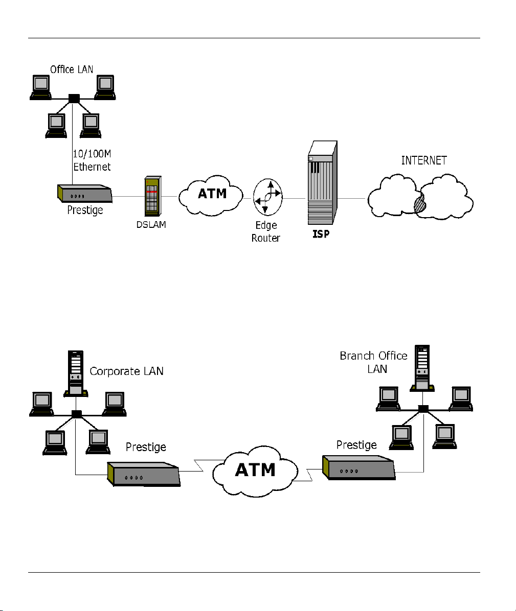
Prestige 645R-A Series User’s Guide
Figure 1-1 Internet Access Application
1.3.2 LAN to LAN Application
You can use the Prestige to connect two geographically dispersed networks through an ADSL line. A typical
LAN-to-LAN application for your Prestige is shown as follows.
Figure 1-2 LAN-to-LAN Application
1-4 Getting To Know Your Prestige
Page 29
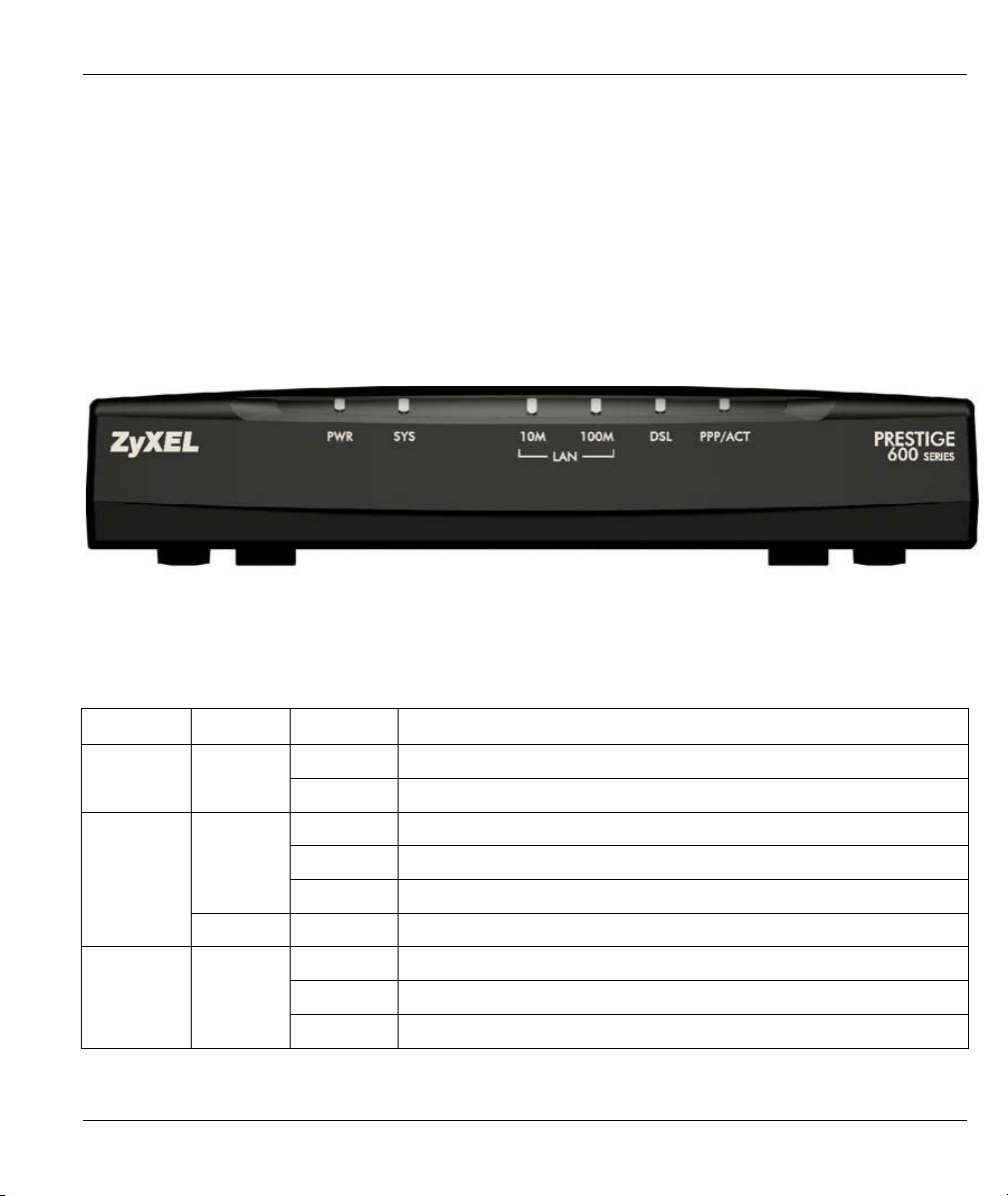
Prestige 645R-A Series User’s Guide
Hardware Installation
This chapter describes the physical features and cable connections of the Prestige.
2.1 Front Panel LEDs of the Prestige
The LED indicators on the front panel indicate the operational status of the Prestige
Figure 2-1 Front Panel
Chapter 2
The table below describes the status of the front panel LEDs.
Table 2-1 Front Panel LED Description
LED
PWR Green On The Prestige is receiving power.
Off The Prestige is not receiving power.
SYS Green On The Prestige is functioning properly.
Blinking The Prestige is rebooting.
Off The Prestige is not ready or has malfunctioned.
Orange On Dying gasp action. The power to the Prestige is too low.
LAN 10M Green On The Prestige has a successful 10Mb Ethernet connection.
Blinking The Prestige is receiving or sending data.
Off No device is connected at 10Mb.
Hardware Installation 2-1
COLOR STATUS DESCRIPTION
Page 30
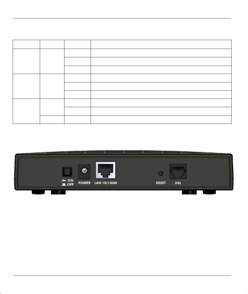
Prestige 645R-A Series User’s Guide
Table 2-1 Front Panel LED Description
LED
LAN 100M Orange On The Prestige has a successful 100Mb Ethernet connection.
Blinking The Prestige is receiving or sending data.
Off No device is connected at 100Mb.
DSL Green
Orange On The Prestige is initiating a PPPoE connection.
COLOR STATUS DESCRIPTION
On The Prestige is linked successfully to a DSLAM.
Blinking The Prestige is initializing the DSL line.
Off The DSL link is down.
Blinking The Prestige is receiving or sending data. PPP/ACT Green
Off The Prestige is ready but not sending or receiving data.
2.2 Rear Panel and Connections
The following figures show the rear panel of your Prestige.
Figure 2-2 Rear Panel
2.2.1 DSL Port
Connect the Prestige directly to the wall jack using the included DSL cable. Connect a microfilter(s) between
the wall jack and your telephone(s). A microfilter acts as low-pass filter (voice transmission takes place in
the 0 to 4KHz bandwidth) and is an optional purchase.
2-2 Hardware Installation
Page 31

Prestige 645R-A Series User’s Guide
2.2.2 One Auto-crossover LAN 10/100M Port
Ethernet 10Base-T/100Base-T networks use Shielded Twisted Pair (STP) cable with RJ-45 that look like a
bigger telephone plug with 8 pins. The LAN port is auto-crossover, so you may use a crossover or a straightthrough Ethernet cable to connect your Prestige to a computer or an external hub.
When the Prestige is on and properly connected to a computer or a hub, the LAN
LED on the front panel turns on.
2.2.3 Using the Reset Button
Hold this button in for more than five seconds to restart the Prestige.
Resetting the Prestige deletes all custom configurations.
2.2.4 Making the Connections
Step 1. Connecting the DSL line
Connect the RJ-11 DSL port on the Prestige to the POTS splitter using the included DSL cable (telephone
wire). Connect the micro filter(s) (optional– see the Splitters and Microfilters appendix for the details)
between the wall jack and your telephone(s). The micro filters act as low pass filters (voice transmission
takes place in the 0 to 4KHz bandwidth).
Step 2. Connecting a computer or an external hub to the Prestige’s 10/100M LAN port
Be careful not to insert an RJ-11 connector into the RJ-45 port.
Ethernet 10Base-T/100Base-T networks use Shielded Twisted Pair (STP) cable with RJ-45 connectors that
look like a bigger telephone plug with 8 pins. The LAN port is auto-crossover, so you may use a crossover or
a straight-through Ethernet cable to connect your Prestige to a computer or an external hub.
Step 3. Connecting the power adaptor to your Prestige
Make sure that you use the supplied power adaptor. See Power Adaptor
Specifications appendix for information.
Connect the power adaptor to the port labeled POWER on the rear panel of your Prestige.
2.3 Additional Installation Requirements
A computer must have a properly installed and enabled Ethernet 10Base-T/100Base-T NIC.
A computer equipped with a web browser (with JavaScript enabled) and/or Telnet.
Hardware Installation 2-3
Page 32

Prestige 645R-A Series User’s Guide
2.4 Turning On Your Prestige
At this point, you should have connected the DSL line, the LAN port and the power port to the appropriate
devices or lines. Push in the power button (located on the back of your Prestige) to turn on your Prestige
2-4 Hardware Installation
Page 33

Prestige 645R-A Series User’s Guide
Chapter 3
Introducing the Web Configurator
This chapter describes how to access and navigate the web configurator.
3.1 Web Configurator Overview
The embedded web configurator allows you to manage the Prestige from anywhere through a browser such
as Microsoft Internet Explorer or Netscape Navigator. Use Internet Explorer 6.0 and later or Netscape
Navigator 7.0 and later versions with JavaScript enabled. It is recommended that you set your screen
resolution to 1024 by 768 pixels
3.2 Accessing the Prestige Web Configurator
Step 1. Make sure your Prestige hardware is properly connected (refer to the Read Me First or the
Hardware Installation chapter).
Step 2. Prepare your computer/computer network to connect to the Prestige (refer to the Read Me
First).
Step 3. Launch your web browser.
Step 4. Type "192.168.1.1" as the URL.
Step 5. An Enter Network Password window displays. Enter the user name (“admin” is the default),
password (“1234” is the default) and click OK.
Figure 3-1 Password Screen
Introducing the Web Configurator 3-1
Page 34

Prestige 645R-A Series User’s Guide
Step 6. You should now see the Site Map screen.
The Prestige automatically times out after five minutes of inactivity. Simply log
back into the Prestige if this happens to you.
3.3 Navigating the Prestige Web Configurator
The following summarizes how to navigate the web configurator from the Site Map screen. Screens vary
slightly for different Prestige models.
Click Wizard Setup to begin a series of screens to configure your Prestige for the first time.
Click a link under Advanced Setup to configure advanced Prestige features.
Click a link under Maintenance to see Prestige performance statistics, upload firmware and back up,
restore or upload a configuration file.
Click SITE MAP to go to the Site Map screen.
Click Logout in the navigation panel when you have finished a Prestige management session.
Wizard Setup
Navigation panel
Logout
Figure 3-2 Web Configurator SITE MAP Screen
Click the HELP icon (located in the top right corner of most screens) to view
embedded help.
3-2 Introducing the Web Configurator
Page 35

Prestige 645R-A Series User’s Guide
3.4 Configuring Password
It is highly recommended that you change the password for accessing the Prestige.
To change your Prestige’s password, click Advanced Setup and then Password. The screen appears as
shown.
Figure 3-3 Password
The following table describes the labels in this screen.
Table 3-1 Password
LABEL DESCRIPTION
Old Password Type the default password or the existing password you use to access the system
in this field.
New Password Type the new password in this field.
Retype to Confirm Type the new password again in this field.
Apply
Reset
Click Apply to save your changes back to the Prestige.
Click Reset to reload the previous configuration for this screen.
Introducing the Web Configurator 3-3
Page 36

Prestige 645R-A Series User’s Guide
3.5 Resetting the Prestige
If you forget your password or cannot access the Prestige, you will need to reload the factory-default
configuration file or use the RESET button the back of the Prestige. Uploading this configuration file
replaces the current configuration file with the factory-default configuration file. This means that you will
lose all configurations that you had previously. The password will be reset to “1234”, also.
3.5.1 Using The Reset Button
Make sure the PWR LED is on (not blinking) when you begin this procedure.
1. Press the RESET button for more than five seconds, then release it. If the PWR LED begins to blink,
the defaults have been restored and the Prestige restarts. Otherwise, go to step 2.
2. Turn the Prestige off.
3. While pressing the RESET button, turn the Prestige on.
Continue to hold the RESET button. The PWR LED will begin to blink and flicker very quickly after about
10 or 15 seconds. This indicates that the defaults have been restored and the Prestige is now restarting.
3-4 Introducing the Web Configurator
Page 37

Prestige 645R-A Series User’s Guide
Chapter 4
Wizard Setup
This chapter provides information on the Wizard Setup screens in the web configurator.
4.1 Wizard Setup Introduction
Use the Wizard Setup screens to configure your system for Internet access settings and fill in the fields with
the information in the Internet Access Checklist table of the Read Me First. Your ISP may have already
configured some of the fields in the wizard screens for you.
4.2 Encapsulation
Be sure to use the encapsulation method required by your ISP. The Prestige supports the following methods.
4.2.1 ENET ENCAP
The MAC Encapsulated Routing Link Protocol (ENET ENCAP) is only implemented with the IP network
protocol. IP packets are routed between the Ethernet interface and the WAN interface and then formatted so
that they can be understood in a bridged environment. For instance, it encapsulates routed Ethernet frames
into bridged ATM cells. ENET ENCAP requires that you specify a gateway IP address in the Ethernet
Encapsulation Gateway field in the second wizard screen. You can get this information from your ISP.
4.2.2 PPP over Ethernet
PPPoE provides access control and billing functionality in a manner similar to dial-up services using PPP.
The Prestige bridges a PPP session over Ethernet (PPP over Ethernet, RFC 2516) from your computer to an
ATM PVC (Permanent Virtual Circuit) which connects to ADSL Access Concentrator where the PPP session
terminates. One PVC can support any number of PPP sessions from your LAN. For more information on
PPPoE, see the appendix.
4.2.3 PPPoA
PPPoA stands for Point to Point Protocol over ATM Adaptation Layer 5 (AAL5). It provides access control
and billing functionality in a manner similar to dial-up services using PPP. The Prestige encapsulates the PPP
session based on RFC1483 and sends it through an ATM PVC (Permanent Virtual Circuit) to the Internet
Service Provider's (ISP) DSLAM (digital access multiplexer). Please refer to RFC 2364 for more information
on PPPoA. Refer to RFC 1661 for more information on PPP.
Wizard Setup 4-1
Page 38

Prestige 645R-A Series User’s Guide
4.2.4 RFC 1483
RFC 1483 describes two methods for Multiprotocol Encapsulation over ATM Adaptation Layer 5 (AAL5).
The first method allows multiplexing of multiple protocols over a single ATM virtual circuit (LLC-based
multiplexing) and the second method assumes that each protocol is carried over a separate ATM virtual
circuit (VC-based multiplexing). Please refer to the RFC for more detailed information.
4.3 Multiplexing
There are two conventions to identify what protocols the virtual circuit (VC) is carrying. Be sure to use the
multiplexing method required by your ISP.
4.3.1 VC-based Multiplexing
In this case, by prior mutual agreement, each protocol is assigned to a specific virtual circuit; for example,
VC1 carries IP, etc. VC-based multiplexing may be dominant in environments where dynamic creation of
large numbers of ATM VCs is fast and economical.
4.3.2 LLC-based Multiplexing
In this case one VC carries multiple protocols with protocol identifying information being contained in each
packet header. Despite the extra bandwidth and processing overhead, this method may be advantageous if it
is not practical to have a separate VC for each carried protocol, for example, if charging heavily depends on
the number of simultaneous VCs.
4.4 VPI and VCI
Be sure to use the correct Virtual Path Identifier (VPI) and Virtual Channel Identifier (VCI) numbers
assigned to you. The valid range for the VPI is 0 to 255 and for the VCI is 32 to 65535 (0 to 31 is reserved
for local management of ATM traffic). Please see the appendix for more information.
4.5 Wizard Setup Configuration: First Screen
In the SITE MAP screen click Wizard Setup to display the first wizard screen.
4-2 Wizard Setup
Page 39

Prestige 645R-A Series User’s Guide
Figure 4-1 Wizard Screen 1
The following table describes the labels in this screen.
Table 4-1 Wizard Screen 1
LABEL DESCRIPTION
Protocol This field contains some pre-configured encapsulation/multiplexing combinations. Choose
from:
PPPoA/VC
PPPoA/LLC
RFC 1483/VC
RFC 1483/LLC
ENET ENCAP/VC
ENET ENCAP/LLC
PPPoE/VC
PPPoE/LLC
Wizard Setup 4-3
Page 40

Prestige 645R-A Series User’s Guide
Table 4-1 Wizard Screen 1
LABEL DESCRIPTION
Virtual Circuit
ID
ATM QoS
Type
Cell Rate Cell rate configuration often helps eliminate traffic congestion that slows transmission of real
Peak Cell Rate Divide the DSL line rate (bps) by 424 (the size of an ATM cell) to find the Peak Cell Rate
Sustain Cell
Maximum
Burst Size
Next Click this button to go to the next wizard screen. The next wizard screen you see depends on
VPI (Virtual Path Identifier) and VCI (Virtual Channel Identifier) define a virtual circuit. Refer to
the appendix for more information.
VPI Enter the VPI assigned to you. This field may already be configured.
VCI Enter the VCI assigned to you. This field may already be configured.
Select CBR (Continuous Bit Rate) to specify fixed (always-on) bandwidth for voice or data
traffic. Select UBR (Unspecified Bit Rate) for applications that are non-time sensitive, such as
e-mail.
time data such as audio and video connections.
(PCR). This is the maximum rate at which the sender can send cells. Type the PCR here.
The Sustain Cell Rate (SCR) sets the average cell rate (long-term) that can be transmitted.
Rate
Type the SCR, which must be less than the PCR.
Maximum Burst Size (MBS) refers to the maximum number of cells that can be sent at the
peak rate. Type the MBS, which is less than 65535.
what protocol you chose above. Click on the protocol link to see the next wizard screen for
that protocol.
4.6 IP Address and Subnet Mask
Similar to the way houses on a street share a common street name, so too do computers on a LAN share one
common network number.
Where you obtain your network number depends on your particular situation. If the ISP or your network
administrator assigns you a block of registered IP addresses, follow their instructions in selecting the IP
addresses and the subnet mask.
If the ISP did not explicitly give you an IP network number, then most likely you have a single user account
and the ISP will assign you a dynamic IP address when the connection is established. If this is the case, it is
recommended that you select a network number from 192.168.0.0 to 192.168.255.0 and you must enable the
4-4 Wizard Setup
Page 41

Prestige 645R-A Series User’s Guide
Network Address Translation (NAT) feature of the Prestige. The Internet Assigned Number Authority
(IANA) reserved this block of addresses specifically for private use; please do not use any other number
unless you are told otherwise. Let's say you select 192.168.1.0 as the network number; which covers 254
individual addresses, from 192.168.1.1 to 192.168.1.254 (zero and 255 are reserved). In other words, the first
three numbers specify the network number while the last number identifies an individual computer on that
network.
Once you have decided on the network number, pick an IP address that is easy to remember, for instance,
192.168.1.1, for your Prestige, but make sure that no other device on your network is using that IP address.
The subnet mask specifies the network number portion of an IP address. Your Prestige will compute the
subnet mask automatically based on the IP address that you entered. You don't need to change the subnet
mask computed by the Prestige unless you are instructed to do otherwise.
4.7 IP Address Assignment
A static IP is a fixed IP that your ISP gives you. A dynamic IP is not fixed; the ISP assigns you a different
one each time. The Single User Account feature can be enabled or disabled if you have either a dynamic or
static IP. However the encapsulation method assigned influences your choices for IP address and ENET
ENCAP Gateway.
4.7.1 IP Assignment with PPPoA or PPPoE Encapsulation
If you have a dynamic IP, then the IP Address and ENET ENCAP Gateway fields are not applicable (N/A). If
you have a static IP, then you only need to fill in the IP Address field and not the ENET ENCAP Gateway
field.
4.7.2 IP Assignment with RFC 1483 Encapsulation
In this case the IP Address Assignment must be static with the same requirements for the IP Address and
ENET ENCAP Gateway fields as stated above.
4.7.3 IP Assignment with ENET ENCAP Encapsulation
In this case you can have either a static or dynamic IP. For a static IP you must fill in all the IP Address and
ENET ENCAP Gateway fields as supplied by your ISP. However for a dynamic IP, the Prestige acts as a
DHCP client on the WAN port and so the IP Address and ENET ENCAP Gateway fields are not applicable
(N/A) as the DHCP server assigns them to the Prestige.
Wizard Setup 4-5
Page 42

Prestige 645R-A Series User’s Guide
4.7.4 Private IP Addresses
Every machine on the Internet must have a unique address. If your networks are isolated from the Internet,
for example, only between your two branch offices, you can assign any IP addresses to the hosts without
problems. However, the Internet Assigned Numbers Authority (IANA) has reserved the following three
blocks of IP addresses specifically for private networks:
10.0.0.0 — 10.255.255.255
172.16.0.0 — 172.31.255.255
192.168.0.0 — 192.168.255.255
You can obtain your IP address from the IANA, from an ISP or it can be assigned from a private network. If
you belong to a small organization and your Internet access is through an ISP, the ISP can provide you with
the Internet addresses for your local networks. On the other hand, if you are part of a much larger
organization, you should consult your network administrator for the appropriate IP addresses.
Regardless of your particular situation, do not create an arbitrary IP address;
always follow the guidelines above. For more information on address assignment,
please refer to RFC 1597, Address Allocation for Private Internets and RFC 1466,
Guidelines for Management of IP Address Space.
4.8 Nailed-Up Connection (PPP)
A nailed-up connection is a dial-up line where the connection is always up regardless of traffic demand. The
Prestige does two things when you specify a nailed-up connection. The first is that idle timeout is disabled.
The second is that the Prestige will try to bring up the connection when turned on and whenever the
connection is down. A nailed-up connection can be very expensive for obvious reasons.
Do not specify a nailed-up connection unless your telephone company offers flat-rate service or you need a
constant connection and the cost is of no concern
4.9 NAT
NAT (Network Address Translation - NAT, RFC 1631) is the translation of the IP address of a host in a
packet, for example, the source address of an outgoing packet, used within one network to a different IP
address known within another network.
4.10 Wizard Setup Configuration: Second Screen
The second wizard screen varies depending on what protocol you use. All screens shown are with routing
mode. Configure the fields and click Next to continue.
4-6 Wizard Setup
Page 43

Prestige 645R-A Series User’s Guide
4.10.1 PPPoE
Select PPPoE from the Protocol drop-down list box in the first wizard screen to display the screen as shown.
Figure 4-2 Internet Connection with PPPoE
The following table describes the labels in this screen.
Table 4-2 Internet Connection with PPPoE
LABEL DESCRIPTION
Service Name Type the name of your PPPoE service here.
User Name
Password Enter the password associated with the user name above.
Configure User Name and Password fields for PPPoA and PPPoE encapsulation only.
Enter the user name exactly as your ISP assigned. If assigned a name in the form
user@domain
as given.
where domain identifies a service name, then enter both components exactly
Wizard Setup 4-7
Page 44

Prestige 645R-A Series User’s Guide
Table 4-2 Internet Connection with PPPoE
LABEL DESCRIPTION
IP Address A static IP address is a fixed IP that your ISP gives you. A dynamic IP address is not fixed;
the ISP assigns you a different one each time you connect to the Internet. The Single User
Account feature can be used with either a dynamic or static IP address.
Select Obtain an IP Address Automatically if you have a dynamic IP address; otherwise
select Static IP Address and type your ISP assigned IP address in the IP Address text box
below.
Connection
Back
Finish
Select Connect on Demand when you don't want the connection up all the time and specify
an idle time-out (in seconds) in the Max. Idle Timeout field. The default setting selects
Connection on Demand with 0 as the idle time-out, which means the Internet session will
not timeout.
Select Nailed-Up Connection when you want your connection up all the time. The Prestige
will try to bring up the connection automatically if it is disconnected.
The schedule rule(s) in SMT menu 26 has priority over your Connection settings.
Click Back to go back to the first wizard screen.
Click Finish to save the settings and proceed to the next wizard screen.
4.10.2 RFC 1483
Select RFC 1483 from the Encapsulation drop-down list box in the first wizard screen to display the screen
as shown.
Figure 4-3 Internet Connection with RFC 1483
4-8 Wizard Setup
Page 45

The following table describes the labels in this screen.
Table 4-3 Internet Connection with RFC 1483
LABEL DESCRIPTION
IP Address Type your ISP assigned IP address in this field.
Prestige 645R-A Series User’s Guide
Back
Finish
Click Back to go back to the first wizard screen.
Click Finish to save the settings and proceed to the next wizard screen.
4.10.3 ENET ENCAP
Select ENET ENCAP from the Encapsulation drop-down list box in the first wizard screen to display the
screen as shown.
Figure 4-4 Internet Connection with ENET ENCAP
The following table describes the labels in this screen.
Wizard Setup 4-9
Page 46

Prestige 645R-A Series User’s Guide
Table 4-4 Internet Connection with ENET ENCAP
LABEL DESCRIPTION
IP Address A static IP address is a fixed IP that your ISP gives you. A dynamic IP address is not
fixed; the ISP assigns you a different one each time you connect to the Internet. The
Single User Account feature can be used with either a dynamic or static IP address.
Select Obtain an IP Address Automatically if you have a dynamic IP address;
otherwise select Static IP Address and type your ISP assigned IP address in the IP
Address text box below.
Subnet Mask Enter a subnet mask in dotted decimal notation.
Refer to the IP Subnetting appendix to calculate a subnet mask If you are implementing
subnetting.
ENET ENCAP
Gateway
Back
Finish
You must specify a gateway IP address (supplied by your ISP) when you use ENET
ENCAP in the Protocol field in the previous screen.
Click Back to go back to the first wizard screen.
Click Finish to save the settings and proceed to the next wizard screen.
4.10.4 PPPoA
Select PPPoA from the Encapsulation drop-down list box in the first wizard screen to display the screen as
shown.
4-10 Wizard Setup
Page 47

Prestige 645R-A Series User’s Guide
Figure 4-5 Internet Connection with PPPoA
The following table describes the labels in this screen.
Table 4-5 Internet Connection with PPPoA
LABEL DESCRIPTION
User Name Enter the user name exactly as your ISP assigned. If assigned a name in the form
user@domain
as given.
Password Enter the password associated with the user name above.
IP Address A static IP address is a fixed IP that your ISP gives you. A dynamic IP address is not fixed;
the ISP assigns you a different one each time you connect to the Internet. The Single User
Account feature can be used with either a dynamic or static IP address.
Click Obtain an IP Address Automatically if you have a dynamic IP address; otherwise
click Static IP Address and type your ISP assigned IP address in the IP Address text box
below.
where domain identifies a service name, then enter both components exactly
Wizard Setup 4-11
Page 48

Prestige 645R-A Series User’s Guide
Table 4-5 Internet Connection with PPPoA
LABEL DESCRIPTION
Connection
Back
Finish
Select Connect on Demand when you don't want the connection up all the time and specify
an idle time-out (in seconds) in the Max. Idle Timeout field. The default setting selects
Connection on Demand with 0 as the idle time-out, which means the Internet session will
not timeout.
Select Nailed-Up Connection when you want your connection up all the time. The Prestige
will try to bring up the connection automatically if it is disconnected.
The schedule rule(s) in SMT menu 26 has priority over your Connection settings.
Click Back to go back to the first wizard screen.
Click Finish to save the settings and proceed to the next wizard screen.
4.11 Basic Setup Complete
Congratulations! You are now set up to access the Internet. Launch your web browser and navigate to
www.zyxel.com
access is just the beginning. Refer to the rest of this User’s Guide for more detailed information on the
complete range of Prestige features. If you cannot access the Internet, open the web configurator again to
confirm that the Internet settings you configured in the Wizard Setup are correct. Also, check your cable
connections and restart the Prestige if necessary.
or click the ZyXEL link, shown in this screen, to test your Internet connection. Internet
Figure 4-6 Wizard Screen 3
4-12 Wizard Setup
Page 49

LAN, NAT and Dynamic DNS
Part II:
LAN, NAT and Dynamic DNS
This part covers LAN (Local Area Network) setup, NAT (Network Address Translation) and dynamic
DNS (Domain Name Sever).
II
Page 50

Page 51

Prestige 645R-A Series User’s Guide
Chapter 5
LAN Setup
This chapter describes how to configure LAN settings.
5.1 LAN Overview
A Local Area Network (LAN) is a shared communication system to which many computers are attached. A
LAN is a computer network limited to the immediate area, usually the same building or floor of a building.
The LAN screens can help you configure a LAN DHCP server and manage IP addresses.
5.1.1 LANs, WANs and the Prestige
The actual physical connection determines whether the Prestige ports are LAN or WAN ports. There are two
separate IP networks, one inside, the LAN network; the other outside: the WAN network as shown next:
Figure 5-1 LAN and WAN IP Addresses
5.2 DNS Server Address
DNS (Domain Name System) is for mapping a domain name to its corresponding IP address and vice versa,
for example, the IP address of www.zyxel.com is 204.217.0.2. The DNS server is extremely important
because without it, you must know the IP address of a machine before you can access it. The DNS server
addresses that you enter in the DHCP setup are passed to the client machines along with the assigned IP
address and subnet mask.
LAN Setup 5-1
Page 52

Prestige 645R-A Series User’s Guide
There are two ways that an ISP disseminates the DNS server addresses. The first is for an ISP to tell a
customer the DNS server addresses, usually in the form of an information sheet, when s/he signs up. If your
ISP gives you the DNS server addresses, enter them in the DNS Server fields in DHCP Setup, otherwise,
leave them blank.
Some ISP’s choose to pass the DNS servers using the DNS server extensions of PPP IPCP (IP Control
Protocol) after the connection is up. If your ISP did not give you explicit DNS servers, chances are the DNS
servers are conveyed through IPCP negotiation. The Prestige supports the IPCP DNS server extensions
through the DNS proxy feature.
If the Primary and Secondary DNS Server fields in DHCP Setup are not specified, for instance, left as
0.0.0.0, the Prestige tells the DHCP clients that it itself is the DNS server. When a computer sends a DNS
query to the Prestige, the Prestige forwards the query to the real DNS server learned through IPCP and relays
the response back to the computer.
Please note that DNS proxy works only when the ISP uses the IPCP DNS server extensions. It does not
mean you can leave the DNS servers out of the DHCP setup under all circumstances. If your ISP gives you
explicit DNS servers, make sure that you enter their IP addresses in the DHCP Setup menu. This way, the
Prestige can pass the DNS servers to the computers and the computers can query the DNS server directly
without the Prestige’s intervention.
5.3 DNS Server Address Assignment
Use DNS (Domain Name System) to map a domain name to its corresponding IP address and vice versa. The
DNS server is extremely important because without it, you must know the IP address of a computer before
you can access it.
There are two ways that an ISP disseminates the DNS server addresses.
1. The ISP tells you the DNS server addresses, usually in the form of an information sheet, when you sign
up. If your ISP gives you DNS server addresses, enter them in the DNS Server fields in DHCP Setup.
2. Leave the DNS Server fields in DHCP Setup blank (for example 0.0.0.0). The Prestige acts as a DNS
proxy when this field is blank.
5.4 LAN TCP/IP
The Prestige has built-in DHCP server capability that assigns IP addresses and DNS servers to systems that
support DHCP client capability.
5.4.1 Factory LAN Defaults
The LAN parameters of the Prestige are preset in the factory with the following values:
IP address of 192.168.1.1 with subnet mask of 255.255.255.0 (24 bits)
DHCP server enabled with 32 client IP addresses starting from 192.168.1.33.
5-2 LAN Setup
Page 53

Prestige 645R-A Series User’s Guide
These parameters should work for the majority of installations. If your ISP gives you explicit DNS server
address(es), read the embedded web configurator help regarding what fields need to be configured.
5.4.2 IP Address and Subnet Mask
Refer to the IP Address and Subnet Mask section in the Wizard Setup chapter for this information.
5.4.3 RIP Setup
RIP (Routing Information Protocol) allows a router to exchange routing information with other routers. The
RIP Direction field controls the sending and receiving of RIP packets. When set to:
1. Both - the Prestige will broadcast its routing table periodically and incorporate the RIP information that
it receives.
2. In Only - the Prestige will not send any RIP packets but will accept all RIP packets received.
3. Out Only - the Prestige will send out RIP packets but will not accept any RIP packets received.
4. None - the Prestige will not send any RIP packets and will ignore any RIP packets received.
The Version field controls the format and the broadcasting method of the RIP packets that the Prestige sends
(it recognizes both formats when receiving). RIP-1 is universally supported; but RIP-2 carries more
information. RIP-1 is probably adequate for most networks, unless you have an unusual network topology.
Both RIP-2B and RIP-2M sends the routing data in RIP-2 format; the difference being that RIP-2B uses
subnet broadcasting while RIP-2M uses multicasting.
5.4.4 Multicast
Traditionally, IP packets are transmitted in one of either two ways - Unicast (1 sender - 1 recipient) or
Broadcast (1 sender - everybody on the network). Multicast delivers IP packets to a group of hosts on the
network - not everybody and not just 1.
IGMP (Internet Group Multicast Protocol) is a network-layer protocol used to establish membership in a
Multicast group - it is not used to carry user data. IGMP version 2 (RFC 2236) is an improvement over
version 1 (RFC 1112) but IGMP version 1 is still in wide use. If you would like to read more detailed
information about interoperability between IGMP version 2 and version 1, please see sections 4 and 5 of
RFC 2236. The class D IP address is used to identify host groups and can be in the range 224.0.0.0 to
239.255.255.255. The address 224.0.0.0 is not assigned to any group and is used by IP multicast computers.
The address 224.0.0.1 is used for query messages and is assigned to the permanent group of all IP hosts
(including gateways). All hosts must join the 224.0.0.1 group in order to participate in IGMP. The address
224.0.0.2 is assigned to the multicast routers group.
The Prestige supports both IGMP version 1 (IGMP-v1) and IGMP version 2 (IGMP-v2). At start up, the
Prestige queries all directly connected networks to gather group membership. After that, the Prestige
periodically updates this information. IP multicasting can be enabled/disabled on the Prestige LAN and/or
WAN interfaces in the web configurator (LAN; WAN). Select None to disable IP multicasting on these
interfaces.
LAN Setup 5-3
Page 54

Prestige 645R-A Series User’s Guide
5.5 Configuring LAN
Click LAN to open the following screen.
Figure 5-2 LAN
The following table describes the labels in this screen.
Table 5-1 LAN
LABEL DESCRIPTION
DHCP
5-4 LAN Setup
Page 55

Prestige 645R-A Series User’s Guide
Table 5-1 LAN
LABEL DESCRIPTION
DHCP
Client IP Pool Starting
Address
Size of Client IP Pool This field specifies the size or count of the IP address pool.
Primary DNS Server Enter the IP addresses of the DNS servers. The DNS servers are passed to the
Secondary DNS Server As above.
Remote DHCP Server
TCP/IP
IP Address Enter the IP address of your Prestige in dotted decimal notation, for example,
If set to Server, your Prestige can assign IP addresses, an IP default gateway
and DNS servers to Windows 95, Windows NT and other systems that support
the DHCP client.
If set to None, the DHCP server will be disabled.
If set to Relay, the Prestige acts as a surrogate DHCP server and relays DHCP
requests and responses between the remote server and the clients. Enter the IP
address of the actual, remote DHCP server in the Remote DHCP Server field in
this case.
When DHCP is used, the following items need to be set:
This field specifies the first of the contiguous addresses in the IP address pool.
DHCP clients along with the IP address and the subnet mask.
If Relay is selected in the DHCP field above then enter the IP address of the
actual remote DHCP server here.
192.168.1.1 (factory default).
IP Subnet Mask Type the subnet mask assigned to you by your ISP (if given).
RIP Direction
RIP Version
Multicast IGMP (Internet Group Multicast Protocol) is a session-layer protocol used to
Apply
Reset
Select the RIP direction from None, Both, In Only and Out Only.
Select the RIP version from RIP-1, RIP-2B and RIP-2M.
establish membership in a multicast group. The Prestige supports both IGMP
version 1 (IGMP-v1) and IGMP-v2. Select None to disable it.
Click Apply to save your changes back to the Prestige.
Click Reset to reload the previous configuration for this screen.
LAN Setup 5-5
Page 56

Page 57

Prestige 645R-A Series User’s Guide
Chapter 6
Network Address Translation (NAT)
This chapter discusses how to configure NAT on the Prestige.
6.1 NAT Overview
NAT (Network Address Translation - NAT, RFC 1631) is the translation of the IP address of a host in a
packet, for example, the source address of an outgoing packet, used within one network to a different IP
address known within another network.
6.1.1 NAT Definitions
Inside/outside denotes where a host is located relative to the Prestige, for example, the computers of your
subscribers are the inside hosts, while the web servers on the Internet are the outside hosts.
Global/local denotes the IP address of a host in a packet as the packet traverses a router, for example, the
local address refers to the IP address of a host when the packet is in the local network, while the global
address refers to the IP address of the host when the same packet is traveling in the WAN side.
Note that inside/outside refers to the location of a host, while global/local refers to the IP address of a host
used in a packet. Thus, an inside local address (ILA) is the IP address of an inside host in a packet when the
packet is still in the local network, while an inside global address (IGA) is the IP address of the same inside
host when the packet is on the WAN side. The following table summarizes this information.
Table 6-1 NAT Definitions
ITEM DESCRIPTION
Inside This refers to the host on the LAN.
Outside This refers to the host on the WAN.
Local This refers to the packet address (source or destination) as the packet travels on the LAN.
Global This refers to the packet address (source or destination) as the packet travels on the WAN.
NAT never changes the IP address (either local or global) of an outside host.
6.1.2 What NAT Does
In the simplest form, NAT changes the source IP address in a packet received from a subscriber (the inside
local address) to another (the inside global address) before forwarding the packet to the WAN side. When
the response comes back, NAT translates the destination address (the inside global address) back to the inside
NAT 6-1
Page 58

Prestige 645R-A Series User’s Guide
local address before forwarding it to the original inside host. Note that the IP address (either local or global)
of an outside host is never changed.
The global IP addresses for the inside hosts can be either static or dynamically assigned by the ISP. In
addition, you can designate servers, for example, a web server and a telnet server, on your local network and
make them accessible to the outside world. With no servers defined, your Prestige filters out all incoming
inquiries, thus preventing intruders from probing your network. For more information on IP address
translation, refer to RFC 1631, The IP Network Address Translator (NAT).
6.1.3 How NAT Works
Each packet has two addresses – a source address and a destination address. For outgoing packets, the ILA
(Inside Local Address) is the source address on the LAN, and the IGA (Inside Global Address) is the source
address on the WAN. For incoming packets, the ILA is the destination address on the LAN, and the IGA is
the destination address on the WAN. NAT maps private (local) IP addresses to globally unique ones required
for communication with hosts on other networks. It replaces the original IP source address (and TCP or UDP
source port numbers for Many-to-One and Many-to-Many Overload NAT mapping) in each packet and then
forwards it to the Internet. The Prestige keeps track of the original addresses and port numbers so incoming
reply packets can have their original values restored. The following figure illustrates this.
Figure 6-1 How NAT Works
6-2 NAT
Page 59

Prestige 645R-A Series User’s Guide
6.1.4 NAT Application
The following figure illustrates a possible NAT application, where three inside LANs (logical LANs using IP
Alias) behind the Prestige can communicate with three distinct WAN networks. More examples follow at the
end of this chapter.
Figure 6-2 NAT Application With IP Alias
6.1.5 NAT Mapping Types
NAT supports five types of IP/port mapping. They are:
1. One to One: In One-to-One mode, the Prestige maps one local IP address to one global IP address.
2. Many to One: In Many-to-One mode, the Prestige maps multiple local IP addresses to one global IP
address. This is equivalent to SUA (for instance, PAT, port address translation), ZyXEL’s Single User
Account feature that previous ZyXEL routers supported (the SUA Only option in today’s routers).
3. Many to Many Overload: In Many-to-Many Overload mode, the Prestige maps the multiple local IP
addresses to shared global IP addresses.
NAT 6-3
Page 60

Prestige 645R-A Series User’s Guide
4. Many-to-Many No Overload: In Many-to-Many No Overload mode, the Prestige maps each local IP
address to a unique global IP address.
5. Server: This type allows you to specify inside servers of different services behind the NAT to be
accessible to the outside world.
Port numbers do not change for One-to-One and Many-to-Many No Overload NAT
mapping types.
The following table summarizes these types.
Table 6-2 NAT Mapping Types
TYPE IP MAPPING SMT ABBREVIATION
One-to-One ILA1 IGA1 1:1
Many-to-One (SUA/PAT) ILA1 IGA1
ILA2 IGA1
…
Many-to-Many Overload ILA1 IGA1
ILA2 IGA2
ILA3 IGA1
ILA4 IGA2
…
Many-to-Many No Overload ILA1 IGA1
ILA2 IGA2
ILA3 IGA3
…
Server Server 1 IP IGA1
Server 2 IP IGA1
Server 3 IP IGA1
M:1
M:M Ov
M:M No OV
Server
6.2 SUA (Single User Account) Versus NAT
SUA (Single User Account) is a ZyNOS implementation of a subset of NAT that supports two types of
mapping, Many-to-One and Server. The Prestige also supports Full Feature NAT to map multiple global
IP addresses to multiple private LAN IP addresses of clients or servers using mapping types as outlined in
Table 6-2.
6-4 NAT
Page 61

Prestige 645R-A Series User’s Guide
1. Choose SUA Only if you have just one public WAN IP address for your Prestige.
2. Choose Full Feature if you have multiple public WAN IP addresses for your Prestige.
6.3 SUA Server
A SUA server set is a list of inside (behind NAT on the LAN) servers, for example, web or FTP, that you can
make visible to the outside world even though SUA makes your whole inside network appear as a single
computer to the outside world.
You may enter a single port number or a range of port numbers to be forwarded, and the local IP address of
the desired server. The port number identifies a service; for example, web service is on port 80 and FTP on
port 21. In some cases, such as for unknown services or where one server can support more than one service
(for example both FTP and web service), it might be better to specify a range of port numbers. You can
allocate a server IP address that corresponds to a port or a range of ports.
Many residential broadband ISP accounts do not allow you to run any server processes (such as a Web or
FTP server) from your location. Your ISP may periodically check for servers and may suspend your account
if it discovers any active services at your location. If you are unsure, refer to your ISP.
Default Server IP Address
In addition to the servers for specified services, NAT supports a default server IP address. A default server
receives packets from ports that are not specified in this screen.
If you do not assign a Default Server IP Address, then all packets received for ports
not specified in this screen will be discarded.
6.3.1 Port Forwarding: Services and Port Numbers
A NAT server set is a list of inside (behind NAT on the LAN) servers, for example, web or FTP, that you can
make accessible to the outside world even though NAT makes your whole inside network appear as a single
machine to the outside world.
Use the SUA Server page to forward incoming service requests to the server(s) on your local network. You
may enter a single port number or a range of port numbers to be forwarded, and the local IP address of the
desired server. The port number identifies a service; for example, web service is on port 80 and FTP on port
21. In some cases, such as for unknown services or where one server can support more than one service (for
example both FTP and web service), it might be better to specify a range of port numbers.
In addition to the servers for specified services, NAT supports a default server. A service request that does
not have a server explicitly designated for it is forwarded to the default server. If the default is not defined,
the service request is simply discarded.
NAT 6-5
Page 62

Prestige 645R-A Series User’s Guide
Many residential broadband ISP accounts do not allow you to run any server
processes (such as a Web or FTP server) from your location. Your ISP may
periodically check for servers and may suspend your account if it discovers any
active services at your location. If you are unsure, refer to your ISP.
The most often used port numbers are shown in the following table. Please refer to RFC 1700 for further
information about port numbers.
Table 6-3 Services and Port Numbers
SERVICES PORT NUMBER
ECHO 7
FTP (File Transfer Protocol) 21
SMTP (Simple Mail Transfer Protocol) 25
DNS (Domain Name System) 53
Finger 79
HTTP (Hyper Text Transfer protocol or WWW, Web) 80
POP3 (Post Office Protocol) 110
NNTP (Network News Transport Protocol) 119
SNMP (Simple Network Management Protocol) 161
SNMP trap 162
PPTP (Point-to-Point Tunneling Protocol) 1723
6.3.2 Configuring Servers Behind SUA (Example)
Let's say you want to assign ports 22-25 to one server, port 80 to another and assign a default server IP
address of 192.168.1.35 as shown in the next figure.
6-6 NAT
Page 63

Prestige 645R-A Series User’s Guide
Figure 6-3 Multiple Servers Behind NAT Example
6.4 Selecting the NAT Mode
Click NAT to open the following screen.
Figure 6-4 NAT Mode
The following table describes the labels in this screen.
NAT 6-7
Page 64

Prestige 645R-A Series User’s Guide
Table 6-4 NAT Mode
LABEL DESCRIPTION
None Select this radio button to disable NAT.
SUA Only
Edit Details
Full Feature Select this radio button if you have multiple public WAN IP addresses for your Prestige.
Edit Details
Apply
Select this radio button if you have just one public WAN IP address for your Prestige. The
Prestige uses Address Mapping Set 1 in the NAT - Edit SUA/NAT Server Set screen.
Click this link to go to the NAT - Edit SUA/NAT Server Set screen.
Click this link to go to the NAT - Address Mapping Rules screen.
Click Apply to save your configuration.
6.5 Configuring SUA Server
If you do not assign an IP Address in Server Set 1 (default server), then all packets
received for ports not specified in this screen will be discarded.
Click NAT, Select SUA Only and click Edit Details to open the following screen.
6-8 NAT
Page 65

Prestige 645R-A Series User’s Guide
Figure 6-5 Edit SUA/NAT Server Set
The following table describes the labels in this screen.
Table 6-5 Edit SUA/NAT Server Set
LABEL DESCRIPTION
Start Port No. Enter a port number in this field.
To forward only one port, enter the port number again in the End Port No. field.
To forward a series of ports, enter the start port number here and the end port number
in the End Port No. field.
NAT 6-9
Page 66

Prestige 645R-A Series User’s Guide
Table 6-5 Edit SUA/NAT Server Set
LABEL DESCRIPTION
End Port No. Enter a port number in this field.
To forward only one port, enter the port number again in the Start Port No. field above
and then enter it again in this field.
To forward a series of ports, enter the last port number in a series that begins with the
port number in the Start Port No. field above.
IP Address Enter your server IP address in this field.
Save
Reset
Click Save to save your changes back to the Prestige.
Click Reset to reload the previous configuration for this screen.
6.6 Configuring Address Mapping
Ordering your rules is important because the Prestige applies the rules in the order that you specify. When a
rule matches the current packet, the Prestige takes the corresponding action and the remaining rules are
ignored. If there are any empty rules before your new configured rule, your configured rule will be pushed up
by that number of empty rules. For example, if you have already configured rules 1 to 6 in your current set
and now you configure rule number 9. In the set summary screen, the new rule will be rule 7, not 9. Now if
you delete rule 4, rules 5 to 7 will be pushed up by 1 rule, so old rules 5, 6 and 7 become new rules 4, 5 and
6.
To change your Prestige’s address mapping settings, click NAT, Select Full Feature and click Edit Details
to open the following screen.
6-10 NAT
Page 67

Prestige 645R-A Series User’s Guide
Figure 6-6 Address Mapping Rules
The following table describes the labels in this screen.
Table 6-6 Address Mapping Rules
LABEL DESCRIPTION
Local Start IP
Local End IP This is the end Inside Local IP Address (ILA). If your rule is for all local IP addresses,
Global Start IP This is the starting Inside Global IP Address (IGA). Enter 0.0.0.0 here if you have a
Global End IP
This is the starting Inside Local IP Address (ILA). Local IP addresses are N/A for Server
port mapping.
then enter 0.0.0.0 as the Local Start IP address and 255.255.255.255 as the Local End
IP address. This field is N/A for One-to-one and Server mapping types.
dynamic IP address from your ISP. You can only do this for Many-to-One and Server
mapping types.
This is the ending Inside Global IP Address (IGA). This field is N/A for One-to-one,
Many-to-One and Server mapping types.
NAT 6-11
Page 68

Prestige 645R-A Series User’s Guide
Table 6-6 Address Mapping Rules
LABEL DESCRIPTION
Type
Back
1-1: One-to-one mode maps one local IP address to one global IP address. Note that
port numbers do not change for the One-to-one NAT mapping type.
M-1: Many-to-One mode maps multiple local IP addresses to one global IP address. This
is equivalent to SUA (i.e., PAT, port address translation), ZyXEL's Single User Account
feature that previous ZyXEL routers supported only.
M-M Ov (Overload): Many-to-Many Overload mode maps multiple local IP addresses to
shared global IP addresses.
MM No (No Overload): Many-to-Many No Overload mode maps each local IP address to
unique global IP addresses.
Server: This type allows you to specify inside servers of different services behind the
NAT to be accessible to the outside world.
Click Back to return to the NAT Mode screen.
6.7 Editing an Address Mapping Rule
To edit an address mapping rule, click the rule’s link in the NAT Address Mapping Rules screen to display
the screen shown next.
Figure 6-7 Address Mapping Rule Edit
The following table describes the labels in this screen.
6-12 NAT
Page 69

Prestige 645R-A Series User’s Guide
Table 6-7 Address Mapping Rule Edit
LABEL DESCRIPTION
Type Choose the port mapping type from one of the following.
1. One-to-One: One-to-One mode maps one local IP address to one global IP
address. Note that port numbers do not change for One-to-one NAT mapping type.
2. Many-to-One: Many-to-One mode maps multiple local IP addresses to one global
IP address. This is equivalent to SUA (i.e., PAT, port address translation), ZyXEL's
Single User Account feature that previous ZyXEL routers supported only.
3. Many-to-Many Overload: Many-to-Many Overload mode maps multiple local IP
addresses to shared global IP addresses.
4. Many-to-Many No Overload: Many-to-Many No Overload mode maps each local
IP address to unique global IP addresses.
5. Server: This type allows you to specify inside servers of different services behind
the NAT to be accessible to the outside world.
Local Start IP
Local End IP This is the end local IP address (ILA). If your rule is for all local IP addresses, then
Global Start IP This is the starting global IP address (IGA). Enter 0.0.0.0 here if you have a dynamic
Global End IP
Server Mapping
Set
Edit Details
Apply
Reset
Delete
This is the starting local IP address (ILA). Local IP addresses are N/A for Server port
mapping.
enter 0.0.0.0 as the Local Start IP address and 255.255.255.255 as the Local End
IP address.
This field is N/A for One-to-One and Server mapping types.
IP address from your ISP.
This is the ending global IP address (IGA). This field is N/A for One-to-One, Many-
to-One and Server mapping types.
Only available when Type is set to Server.
Select a number from 1 to 10 from the drop-down menu to choose a server set from
the NAT - Address Mapping Rules screen.
Click this link to go to the NAT - Edit SUA/NAT Server Set screen to edit a server
set that you have selected in the Server Mapping Set field.
Click Apply to save your changes back to the Prestige.
Click Reset to reload the previous configuration for this screen.
Click Delete to exit this screen without saving
NAT 6-13
Page 70

Page 71

Prestige 645R-A Series User’s Guide
Chapter 7
Dynamic DNS Setup
This chapter discusses how to configure your Prestige to use Dynamic DNS.
7.1 Dynamic DNS
Dynamic DNS allows you to update your current dynamic IP address with one or many dynamic DNS
services so that anyone can contact you (in NetMeeting, CU-SeeMe, etc.). You can also access your FTP
server or Web site on your own computer using a DNS-like address (for instance myhost.dhs.org, where
myhost is a name of your choice) that will never change instead of using an IP address that changes each
time you reconnect. Your friends or relatives will always be able to call you even if they don't know your IP
address.
First of all, you need to have registered a dynamic DNS account with www.dyndns.org. This is for people
with a dynamic IP from their ISP or DHCP server that would still like to have a DNS name. The Dynamic
DNS service provider will give you a password or key.
7.1.1 DYNDNS Wildcard
Enabling the wildcard feature for your host causes *.yourhost.dyndns.org to be aliased to the same IP address
as yourhost.dyndns.org. This feature is useful if you want to be able to use, for example,
www.yourhost.dyndns.org and still reach your hostname.
If you have a private WAN IP address, then you cannot use Dynamic DNS.
7.2 Configuring Dynamic DNS
To change your Prestige’s DDNS, click Dynamic DNS. The screen appears as shown.
Dynamic DNS Setup 7-1
Page 72

Prestige 645R-A Series User’s Guide
Figure 7-1 DDNS
The following table describes the labels in this screen.
Table 7-1 DDNS
LABEL DESCRIPTION
Active Select this check box to use dynamic DNS.
Service Provider Select the name of your Dynamic DNS service provider.
Host Name Type the domain name assigned to your Prestige by your Dynamic DNS provider.
E-mail Address Type your e-mail address.
User Type your user name.
Password Type the password assigned to you.
Enable Wildcard Select this check box to enable DYNDNS Wildcard.
Apply
Reset
Click Apply to save your changes back to the Prestige.
Click Reset to reload the previous configuration for this screen.
7-2 Dynamic DNS Setup
Page 73

Maintenance
Part III:
Maintenance
This part covers the maintenance screens.
III
Page 74

Page 75

Prestige 645R-A Series User’s Guide
Chapter 8
Maintenance
This chapter displays system information such as ZyNOS firmware, port IP addresses and port
traffic statistics.
8.1 Maintenance Overview
Use the maintenance screens to view system information, upload new firmware, manage configuration and
restart your Prestige.
8.2 System Status Screen
Click System Status to open the following screen, where you can use to monitor your Prestige. Note that
these fields are READ-ONLY and are meant to be used for diagnostic purposes.
Maintenance 8-1
Page 76

Prestige 645R-A Series User’s Guide
Figure 8-1 System Status
The following table describes the labels in this screen.
8-2 Maintenance
Page 77

Prestige 645R-A Series User’s Guide
Table 8-1 System Status
LABEL DESCRIPTION
System Status
System Name This is the name of your Prestige. It is for identification purposes.
ZyNOS F/W Version This is the ZyNOS firmware version and the date created. ZyNOS is ZyXEL's
proprietary Network Operating System design.
DSL FW Version This is the DSL firmware version associated with your Prestige.
Standard This is the standard that your Prestige is using.
WAN Information
IP Address This is the WAN port IP address.
IP Subnet Mask This is the WAN port IP subnet mask.
Default Gateway This is the IP address of the default gateway, if applicable.
VPI/VCI This is the Virtual Path Identifier and Virtual Channel Identifier that you entered
in the first Wizard screen.
LAN Information
MAC Address This is the MAC (Media Access Control) or Ethernet address unique to your
Prestige.
IP Address This is the LAN port IP address.
IP Subnet Mask This is the LAN port IP subnet mask.
DHCP
DHCP Start IP This is the first of the contiguous addresses in the IP address pool.
DHCP Pool Size This is the number of IP addresses in the IP address pool.
This is the WAN port DHCP role - Server, Relay (not all Prestige models) or
None.
Maintenance 8-3
Page 78

Prestige 645R-A Series User’s Guide
LABEL DESCRIPTION
Table 8-1 System Status
Show Statistics
Click Show Statistics to see router performance statistics such as number of
packets sent and number of packets received for each port.
8.2.1 System Statistics
Click Show Statistics in the System Status screen to open the following screen. Read-only information here
includes port status and packet specific statistics. Also provided are "system up time" and "poll interval(s)".
The Poll Interval(s) field is configurable.
Figure 8-2 System Status: Show Statistics
8-4 Maintenance
Page 79

Prestige 645R-A Series User’s Guide
The following table describes the labels in this screen.
Table 8-2 System Status: Show Statistics
LABEL DESCRIPTION
System up Time This is the elapsed time the system has been up.
WAN Port Statistics This is the WAN port.
Link Status This is the status of your WAN link.
Upstream Speed This is the upstream speed of your Prestige.
Downstream Speed This is the downstream speed of your Prestige.
Node-Link This field displays the remote node index number and link type. Link types are PPPoA,
ENET, RFC 1483 and PPPoE.
Status For the WAN port, this displays the port speed and duplex setting if you're using Ethernet
encapsulation and down (line is down), idle (line (ppp) idle), dial (starting to trigger a
call) and drop (dropping a call) if you're using PPPoE encapsulation.
For a LAN port, this shows the port speed and duplex setting.
LAN Port Statistics This is the LAN port.
TxPkts This field displays the number of packets transmitted on this port.
RxPkts This field displays the number of packets received on this port.
Errors This field displays the number of error packets on this port.
Tx B/s This field displays the number of bytes transmitted in the last second.
Rx B/s This field displays the number of bytes received in the last second.
Up Time This field displays the elapsed time this port has been up.
Collisions This is the number of collisions on this port.
CPU Load This field specifies the percentage of CPU utilization.
Poll Interval(s) Type the time interval for the browser to refresh system statistics.
Maintenance 8-5
Page 80

Prestige 645R-A Series User’s Guide
Table 8-2 System Status: Show Statistics
LABEL DESCRIPTION
Set Interval
Stop Click this button to halt the refreshing of the system statistics.
Click this button to apply the new poll interval you entered in the Poll Interval field
above.
8.3 DHCP Table Screen
DHCP (Dynamic Host Configuration Protocol, RFC 2131 and RFC 2132) allows individual clients to obtain
TCP/IP configuration at start-up from a server. You can configure the Prestige as a DHCP server or disable
it. When configured as a server, the Prestige provides the TCP/IP configuration for the clients. If set to None,
DHCP service will be disabled and you must have another DHCP server on your LAN, or else the computer
must be manually configured.
Click MAINTENANCE, and then the DHCP Table tab. Read-only information here relates to your DHCP
status. The DHCP table shows current DHCP client information (including IP Address, Host Name and
MAC Address) of all network clients using the DHCP server.
Figure 8-3 DHCP Table
The following table describes the labels in this screen.
Table 8-3 DHCP Table
LABEL DESCRIPTION
Host Name This is the name of the host computer.
IP Address
This field displays the IP address relative to the Host Name field.
8-6 Maintenance
Page 81

Prestige 645R-A Series User’s Guide
Table 8-3 DHCP Table
LABEL DESCRIPTION
MAC
Address
This field displays the MAC (Media Access Control) address of the computer with the displayed
host name.
Every Ethernet device has a unique MAC address. The MAC address is assigned at the factory
and consists of six pairs of hexadecimal characters, for example, 00:A0:C5:00:00:02.
8.4 Diagnostic Screens
These read-only screens display information to help you identify problems with the Prestige.
Click Diagnostic to display the following screen.
Figure 8-4 Diagnostic
8.4.1 Diagnostic General Screen
Click Diagnostic and then General to open the screen shown next.
Maintenance 8-7
Page 82

Prestige 645R-A Series User’s Guide
Figure 8-5 Diagnostic General
The following table describes the labels in this screen.
Table 8-4 Diagnostic General
LABEL DESCRIPTION
TCP/IP
Address
Ping Click this button to ping the IP address that you entered.
Reset
System
Type the IP address of a computer that you want to ping in order to test a connection.
Click this button to reboot the Prestige. A warning dialog box is then displayed asking you if
you're sure you want to reboot the system. Click OK to proceed.
8-8 Maintenance
Page 83

Prestige 645R-A Series User’s Guide
Table 8-4 Diagnostic General
LABEL DESCRIPTION
Back
Click this button to go back to the main Diagnostic screen.
8.4.2 Diagnostic DSL Line Screen
Click Diagnostic and then DSL Line to open the screen shown next.
Figure 8-6 Diagnostic DSL Line
The following table describes the labels in this screen.
Maintenance 8-9
Page 84

Prestige 645R-A Series User’s Guide
Table 8-5 Diagnostic DSL Line
LABEL DESCRIPTION
Reset ADSL
Line
ATM Status Click this button to view ATM status.
ATM Loopback
Test
Upstream Noise
Margin
Downstream
Noise Margin
Back
Click this button to reinitialize the ADSL line. The large text box above then displays the
progress and results of this operation, for example:
"Start to reset ADSL
Loading ADSL modem F/W...
Reset ADSL Line Successfully!"
Click this button to start the ATM loopback test. Make sure you have configured at least
one PVC with proper VPIs/VCIs before you begin this test. The Prestige sends an OAM
F5 packet to the DSLAM/ATM switch and then returns it (loops it back) to the Prestige.
The ATM loopback test is useful for troubleshooting problems with the DSLAM and ATM
network.
Click this button to display the upstream noise margin.
Click this button to display the downstream noise margin.
Click this button to go back to the main Diagnostic screen.
8.5 Firmware Screen
Find firmware at www.zyxel.com in a file that (usually) uses the system model name with a "*.bin"
extension, e.g., "Prestige.bin". The upload process uses FTP (File Transfer Protocol) and may take up to two
minutes. After a successful upload, the system will reboot. See the Firmware and Configuration File
Maintenance chapter in the parts that document the SMT for upgrading firmware using FTP/TFTP
commands.
Only use firmware for your Prestige’s specific model. Refer to the label on the
bottom of your Prestige.
Click Firmware to open the following screen. Follow the instructions in this screen to upload firmware to
your Prestige.
8-10 Maintenance
Page 85

Prestige 645R-A Series User’s Guide
Figure 8-7 Firmware Upgrade
The following table describes the labels in this screen.
Table 8-6 Firmware Upgrade
LABEL DESCRIPTION
File Path
Browse...
Upload
Reset Click this button to clear all user-entered configuration information and return the Prestige to
Type in the location of the file you want to upload in this field or click Browse ... to find it.
Click Browse... to find the .bin file you want to upload. Remember that you must decompress
compressed (.zip) files before you can upload them.
Click Upload to begin the upload process. This process may take up to two minutes.
its factory defaults. Refer to the Resetting the Prestige section.
Do not turn off the Prestige while firmware upload is in progress!
After you see the Firmware Upload in Process screen, wait two minutes before logging into the Prestige
again.
Maintenance 8-11
Page 86

Prestige 645R-A Series User’s Guide
The Prestige automatically restarts in this time causing a temporary network disconnect. In some operating
systems, you may see the following icon on your desktop.
Figure 8-8 Network Temporarily Disconnected
After two minutes, log in again and check your new firmware version in the System Status screen.
If the upload was not successful, the following screen will appear. Click Back to go back to the Firmware
screen.
Figure 8-9 Error Message
8-12 Maintenance
Page 87

SMT General Configuration
Part IV:
SMT General Configuration
This part covers System Management Terminal configuration for general setup, Ethernet setup,
Internet access, remote nodes, remote node TCP/IP, static routing and NAT.
See the web configurator parts of this guide for background information on
features configurable by web configurator and SMT.
IV
Page 88

Page 89

Prestige 645R-A Series User’s Guide
Chapter 9
Introducing the SMT
This chapter explains how to access and navigate the System Management Terminal and gives an
overview of its menus.
9.1 SMT Introduction
The Prestige’s SMT (System Management Terminal) is a menu-driven interface that you can access from a
terminal emulator through the console port or over a telnet connection.
9.1.1 Procedure for SMT Configuration via Telnet
The following procedure details how to telnet into your Prestige.
Step 1. In Windows, click Start (usually in the bottom left corner), Run and then type “telnet
192.168.1.1” (the default IP address) and click OK.
Step 2. For your first login, enter the default password “1234”. As you type the password, the screen
displays an asterisk “*” for each character you type.
Password : xxxx
Figure 9-1 Login Screen
Step 3. After entering the password you will see the main menu.
Please note that if there is no activity for longer than five minutes (default timeout period) after you log in,
your Prestige will automatically log you out. You will then have to telnet into the Prestige again.
9.1.2 Prestige SMT Menu Overview
We use the Prestige 645R-A1 SMT menus in this guide as an example. The SMT menus vary slightly for
different Prestige models.
The following figure gives you an overview of the various SMT menu screens of your Prestige.
Introducing the SMT 9-1
Page 90

Prestige 645R-A Series User’s Guide
Prestige Main Menu
Menu 1
General Setup
Menu 1.1
Configure Dynamic DNS
Menu 3.2.1
IP Alias Setup
Menu 3
Ethernet Setup
Menu 3.1
General Ethernet Setup
Menu 3.2
TCP/IP and DHCP
Ethernet Setup
Menu 24.7.2
System Ma intenance --
Upload System
Configuration File
Menu 4
Internet Access Setup
Menu 11.6
Remote Node ATM
Layer Opt ions
Menu 26
Schedule Setup
Menu 26.x
Schedule Set Setup
Menu 24.7.1
System Ma intenance --
Upload System Firmware
Menu 11
Remote Node Setup
Menu 11.1
Remote Node Profile
Menu 11.3
Remote Node Network
Layer Opt ions
Menu 11.5
Remote No de Filter
Menu 25
IP Routing P olicy Setup
Menu 25.1
IP Routing P olicy Setup
Menu 25.1.1
IP Routing Policy
Menu 24.8
Command Interpreter
Mode
Menu 24.7
System Ma intenance --
Upload Firmware
Menu 12
Static Route Setup
Menu 12.1
IP Static Route Setup
Menu 12.3
Bridge Static
Route Setup
Menu 24
System Ma intenance
Menu 24.1
System Ma intenance --
Status
Menu 24.2
System Information and
Console P ort Speed
Menu 24.3
System Ma intenance --
Log and Trace
Menu 24.4
System Ma intenance --
Diagnostic
Menu 12.1.1
Edit IP Static Route
Menu 12.3.1
Edit Brid ge
Static R oute
Menu 23
System Passw ord
Menu 24.2.1
System Ma intenance --
Information
Menu 24.3.1
System Ma intenance --
View Erro r Log
Menu 15
Menu 15
NAT Setup
NAT Setup
Menu 15.1
Address Mapping Sets
Menu 15.2
NAT Server Sets
Menu 22
SNMP Configuration
Menu 24.2.2
System Ma intenance --
Change Console Port
Speed
Menu 24.3.2
System Ma intenance --
UNIX Syslog
Menu 15.1.x
Address Mapping Rules
Menu 15.2.x
NAT Server Setup
Menu 21.x.1
TCP/IP Filter Rule
Menu 15.1.x.x
Address Mapping Rule
Menu 21
Filter Set Configuration
Menu 21.x
Filter Rules Summary
Menu 21.x.1
Generic Filter R ule
Menu 24.6
System Ma intenance --
Restore Co nfiguration
Menu 24.5
System Ma intenance --
Backup Configuration
Figure 9-2 Prestige 645R-A1 SMT Menu Overview
9.2 Navigating the SMT Interface
The SMT (System Management Terminal) is the interface that you use to configure your Prestige.
Several operations that you should be familiar with before you attempt to modify the configuration are
listed in the table below.
9-2 Introducing the SMT
Page 91

Prestige 645R-A Series User’s Guide
Table 9-1 Main Menu Commands
OPERATION KEYSTROKE DESCRIPTION
Move down to
another menu
Move up to a
previous menu
Move to a “hidden”
menu
Move the cursor [ENTER] or
Entering
information
Required fields
N/A fields <N/A> Some of the fields in the SMT will show a <N/A>. This symbol
Save your
configuration
Exit the SMT Type 99, then press
[ENTER] To move forward to a submenu, type in the number of the desired
submenu and press [ENTER].
[ESC] Press [ESC] to move back to the previous menu.
Press [SPACE
BAR] to change No
to Yes then press
[ENTER].
[UP]/[DOWN] arrow
keys.
Type in or press
[SPACE BAR], then
press [ENTER].
? > or ChangeMe
<
[ENTER] Save your configuration by pressing [ENTER] at the message
[ENTER].
Fields beginning with “Edit” lead to hidden menus and have a
default setting of No. Press [SPACE BAR] once to change No to
Yes, then press [ENTER] to go to the “hidden” menu.
Within a menu, press [ENTER] to move to the next field. You can
also use the [UP]/[DOWN] arrow keys to move to the previous
and the next field, respectively.
You need to fill in two types of fields. The first requires you to type
in the appropriate information. The second allows you to cycle
through the available choices by pressing [SPACE BAR].
All fields with the symbol <?> must be filled in order to be able to
save the new configuration.
All fields with ChangeMe must not be left blank in order to be
able to save the new configuration.
refers to an option that is Not Applicable.
“Press ENTER to confirm or ESC to cancel”. Saving the data on
the screen will take you, in most cases to the previous menu.
Type 99 at the main menu prompt and press [ENTER] to exit the
SMT interface.
After you enter the password, the SMT displays the main menu, as shown next.
Introducing the SMT 9-3
Page 92

Prestige 645R-A Series User’s Guide
Copyright (c) 1994 - 2003 ZyXEL Communications Corp.
Prestige 645R-A Main Menu
Getting Started Advanced Management
1. General Setup 21. Filter Set Configuration
3. Ethernet Setup 22. SNMP Configuration
4. Internet Access Setup 23. System Password
24. System Maintenance
Advanced Applications 25. IP Routing Policy Setup
11. Remote Node Setup 26. Schedule Setup
12. Static Routing Setup
15. NAT Setup 99. Exit
Enter Menu Selection Number:
Figure 9-3 SMT Main Menu
9.2.1 System Management Terminal Interface Summary
Table 9-2 Main Menu Summary
# MENU TITLE DESCRIPTION
1 General Setup Use this menu to set up your general information.
3 Ethernet Setup Use this menu to set up your Ethernet connection.
4 Internet Access Setup A quick and easy way to set up an Internet connection.
11 Remote Node Setup Use this menu to set up the Remote Node for LAN-to-LAN connection,
including Internet connection.
12 Static Routing Setup Use this menu to set up static routes.
15 NAT Setup Use this menu to specify inside servers when NAT is enabled.
21 Filter Set Configuration Use this menu to set up filters to provide security, etc.
22 SNMP Configuration Use this menu to set up SNMP related parameters.
23 System Password Use this menu to change your password.
24 System Maintenance This menu provides system status, diagnostics, software upload, etc.
25 IP Routing Policy Setup Use this menu to configure your IP routing policy.
26 Schedule Setup Use this menu to schedule outgoing calls.
99 Exit Use this to exit from SMT and return to a blank screen.
9-4 Introducing the SMT
Page 93

Prestige 645R-A Series User’s Guide
9.3 Changing the System Password
Change the Prestige default password by following the steps shown next.
Step 1. Enter 23 in the main menu to display Menu 23 - System Security as shown next.
Step 2. Type your existing system password in the Old Password field, for example “1234”, and press
[ENTER].
Menu 23 – System Password
Old Password= ?
New Password= ?
Retype to confirm= ?
Enter here to CONFIRM or ESC to CANCEL:
Figure 9-4 Menu 23 System Password
Step 3. Type your new system password in the New Password field (up to 30 characters), and press
[ENTER].
Step 4. Re-type your new system password in the Retype to confirm field for confirmation and press
[ENTER].
Note that as you type a password, the screen displays an “*” for each character you type.
Introducing the SMT 9-5
Page 94

Page 95

Prestige 645R-A Series User’s Guide
Chapter 10
General Setup
Menu 1 - General Setup contains administrative and system-related information.
10.1 General Setup
Menu 1 — General Setup contains administrative and system-related information (shown next). The
System Name field is for identification purposes. However, because some ISPs check this name you should
enter your computer's "Computer Name".
• In Windows 95/98 click Start, Settings, Control Panel, Network. Click the Identification tab,
note the entry for the Computer name field and enter it as the Prestige System Name.
• In Windows 2000 click Start, Settings, Control Panel and then double-click System. Click the
Network Identification tab and then the Properties button. Note the entry for the Computer
name field and enter it as the Prestige System Name.
• In Windows XP, click start, My Computer, View system information and then click the
Computer Name tab. Note the entry in the Full computer name field and enter it as the Prestige
System Name.
The Domain Name entry is what is propagated to the DHCP clients on the LAN. If you leave this blank,
the domain name obtained by DHCP from the ISP is used. While you must enter the host name (System
Name) on each individual computer, the domain name can be assigned from the Prestige via DHCP.
10.2 Configuring Menu 1
Enter 1 in the Main Menu to open Menu 1 — General Setup (shown next).
General Setup 10-1
Page 96

Prestige 645R-A Series User’s Guide
Menu 1 - General Setup
System Name= P645R-A1
Location=
Contact Person's Name=
Domain Name=
Edit Dynamic DNS= No
Route IP= Yes
Bridge= No
Figure 10-1 Menu 1 General Setup
Fill in the required fields. Refer to the table shown next for more information about these fields.
Table 10-1 Menu 1 General Setup
FIELD DESCRIPTION EXAMPLE
System Name Enter a descriptive name for identification purposes. This name can be
up to 30 alphanumeric characters long. Spaces are not allowed, but
dashes “-” and underscores "_" are accepted.
Location (optional) Enter the geographic location (up to 31 characters) of your Prestige. MyHouse
Contact Person's
Name (optional)
Enter the name (up to 30 characters) of the person in charge of this
Prestige.
Domain Name Enter the domain name (if you know it) here. If you leave this field
blank, the ISP may assign a domain name via DHCP. You can go to
menu 24.8 and type "sys domainname" to see the current domain
name used by your gateway.
If you want to clear this field just press the [SPACE BAR]. The domain
name entered by you is given priority over the ISP assigned domain
name.
Edit Dynamic DNS
Press the [SPACE BAR] to select Yes or No (default). Select Yes to
configure Menu 1.1 — Configure Dynamic DNS (discussed next).
Route IP
Set this field to Yes to enable or No to disable IP routing. You must
enable IP routing for Internet access.
Bridge Turn on/off bridging for protocols not supported (for example, SNA) or
not turned on in the previous Route IP field. Select Yes to turn
bridging on; select No to turn bridging off.
P645R-A1
JohnDoe
zyxel.com.tw
No
Yes
No
10-2 General Setup
Page 97

Prestige 645R-A Series User’s Guide
10.2.1 Configuring Dynamic DNS
If you have a private WAN IP address, then you cannot use Dynamic DNS.
To configure Dynamic DNS, go to Menu 1 — General Setup and select Yes in the Edit Dynamic DNS
field. Press [ENTER] to display Menu 1.1— Configure Dynamic DNS as shown next.
Menu 1.1 - Configure Dynamic DNS
Service Provider = WWW.DynDNS.ORG
Active= Yes
Host= me.ddns.org
EMAIL= mail@mailserver
USER= username
Password= *********
Enable Wildcard= No
Press ENTER to confirm or ESC to cancel:
Figure 10-2 Menu 1.1 Configure Dynamic DNS
Follow the instructions in the next table to configure Dynamic DNS parameters.
Table 10-2 Menu 1.1 Configure Dynamic DNS
FIELD DESCRIPTION EXAMPLE
Service Provider This is the name of your Dynamic DNS service provider. WWW.DynDNS.ORG
Active
Host Enter the domain name assigned to your Prestige by your
EMAIL Enter your e-mail address. mail@mailserver
USER Enter your user name.
Password Enter the password assigned to you.
Enable Wildcard Your Prestige supports DYNDNS Wildcard. Press [SPACE
When you have completed this menu, press [ENTER] at the prompt “Press ENTER to Confirm…” to save
your configuration, or press [ESC] at any time to cancel.
Press [SPACE BAR] to select Yes and then press [ENTER] to
make dynamic DNS active.
Dynamic DNS provider.
BAR] and then [ENTER] to select Yes or No This field is N/A
when you choose DDNS client as your service provider.
(default)
Yes
me.dyndns.org
No
General Setup 10-3
Page 98

Page 99

Prestige 645R-A Series User’s Guide
Chapter 11
Ethernet Setup
This chapter covers how to configure your wired Local Area Network (LAN) settings.
11.1 Ethernet Setup
This section describes how to configure the Ethernet using Menu 3 — Ethernet Setup. From the main
menu, enter 3 to display menu 3.
Menu 3 - Ethernet Setup
1. General Setup
2. TCP/IP and DHCP Setup
Enter Menu Selection Number:
Figure 11-1 Menu 3 Ethernet Setup
11.1.1 General Ethernet Setup
This menu allows you to specify filter set(s) that you wish to apply to the Ethernet traffic. You seldom
need to filter Ethernet traffic; however, the filter sets may be useful to block certain packets, reduce traffic
and prevent security breaches.
Menu 3.1 - General Ethernet Setup
Input Filter Sets:
protocol filters=
device filters=
Output Filter Sets:
protocol filters=
device filters=
Press ENTER to Confirm or ESC to Cancel:
Figure 11-2 Menu 3.1 General Ethernet Setup
If you need to define filters, please read the Filter Set Configuration chapter first, then return to this menu
to define the filter sets.
Ethernet Setup 11-1
Page 100

Prestige 645R-A Series User’s Guide
11.2 Protocol Dependent Ethernet Setup
Depending on the protocols for your applications, you need to configure the respective Ethernet Setup, as
outlined below.
For TCP/IP Ethernet setup refer to the Internet Access Application chapter.
For bridging Ethernet setup refer to the Bridging Setup chapter.
11.3 TCP/IP Ethernet Setup and DHCP
Use menu 3.2 to configure your Prestige for TCP/IP.
To edit menu 3.2, enter 3 from the main menu to display Menu 3 — Ethernet Setup. When menu 3
appears, press 2 and press [ENTER] to display Menu 3.2 — TCP/IP and DHCP Ethernet Setup, as
shown next
Follow the instructions in the following table on how to configure the DHCP fields.
:
Menu 3.2 - TCP/IP and DHCP Ethernet Setup
DHCP Setup:
DHCP= Server
Client IP Pool Starting Address= 192.168.1.33
Size of Client IP Pool= 32
Primary DNS Server= 0.0.0.0
Secondary DNS Server= 0.0.0.0
Remote DHCP Server= N/A
TCP/IP Setup:
IP Address= 192.68.1.1
IP Subnet Mask= 255.255.255.0
RIP Direction= Both
Version= RIP-1
Multicast= None
IP Policies=
Edit IP Alias= No
Press ENTER to Confirm or ESC to Cancel:
Press Space Bar to Toggle.
Figure 11-3 Menu 3.2 TCP/IP and DHCP Ethernet Setup
First address in
the IP pool
Size of the IP
Pool
IP addresses of
the DNS
servers
This is the IP
address of the
Prestige
11-2 Ethernet Setup
 Loading...