


Quick Start Guide
VMG1312-B10C
Wireless N VDSL2 4-port Gateway with USB
Version 1.00
Edition 1, 10/2014
User’s Guide
Default Login Details
LAN IP Address http://192.168.1.1
Login admin
Password 1234
www.zyxel.com
Copyright © 2014 ZyXEL Communications Corporation

IMPORTANT!
READ CAREFULLY BEFORE USE.
KEEP THIS GUIDE FOR FUTURE REFERENCE.
Screenshots and graphics in this book may differ slightly from your product due to differences in
your product firmware or your computer operating system. Every effort has been made to ensure
that the information in this manual is accurate.
Related Documentation
•Quick Start Guide
The Quick Start Guide shows how to connect the Device and get up and running right away.
VMG1312-B10C User’s Guide2

Contents Overview
Contents Overview
User’s Guide .......................................................................................................................................15
Introducing the Device ............................................................................................................................17
The Web Configurator ............................................................................................................................. 23
Quick Start ...............................................................................................................................................31
Technical Reference ..........................................................................................................................33
Network Map and Status Screens ...........................................................................................................35
Broadband ...............................................................................................................................................39
Wireless .................................................................................................................................................. 65
Home Networking ..................................................................................................................................101
Routing ..................................................................................................................................................125
Quality of Service (QoS) .......................................................................................................................131
Network Address Translation (NAT) ......................................................................................................149
Dynamic DNS Setup .............................................................................................................................167
Interface Group .....................................................................................................................................171
USB Service ..........................................................................................................................................177
Firewall ..................................................................................................................................................183
MAC Filter .............................................................................................................................................193
Parental Control ....................................................................................................................................195
Scheduler Rule ......................................................................................................................................199
Certificates ............................................................................................................................................201
VPN ....................................................................................................................................................... 209
Log .......................................................................................................................................................221
Traffic Status ........................................................................................................................................225
ARP Table .............................................................................................................................................229
Routing Table ........................................................................................................................................ 231
IGMP Status .........................................................................................................................................233
xDSL Statistics ...................................................................................................................................... 235
3G Statistics ......................................................................................................................................... 239
User Account .........................................................................................................................................241
Remote Management ............................................................................................................................243
TR-069 Client ........................................................................................................................................ 245
TR-064 ..................................................................................................................................................247
Time Settings ........................................................................................................................................249
E-mail Notification .................................................................................................................................253
Logs Setting .........................................................................................................................................255
Firmware Upgrade ................................................................................................................................259
Configuration .........................................................................................................................................261
VMG1312-B10C User’s Guide
3

Contents Overview
Diagnostic .............................................................................................................................................265
Troubleshooting .................................................................................................................................... 271
4
VMG1312-B10C User’s Guide

Table of Contents
Table of Contents
Contents Overview ..............................................................................................................................3
Table of Contents .................................................................................................................................5
Part I: User’s Guide .........................................................................................15
Chapter 1
Introducing the Device.......................................................................................................................17
1.1 Overview ...........................................................................................................................................17
1.2 Ways to Manage the Device .............................................................................................................17
1.3 Good Habits for Managing the Device .............................................................................................. 17
1.4 Applications for the Device ...............................................................................................................18
1.4.1 Internet Access ........................................................................................................................18
1.4.2 Device’s USB Support .............................................................................................................19
1.5 LEDs (Lights) .................................................................................................................................... 20
1.6 The RESET Button ............................................................................................................................20
1.7 Wireless Access ................................................................................................................................21
1.7.1 Using the WLAN/WPS Button .................................................................................................21
Chapter 2
The Web Configurator........................................................................................................................23
2.1 Overview ...........................................................................................................................................23
2.1.1 Accessing the Web Configurator ............................................................................................. 23
2.2 Web Configurator Layout ..................................................................................................................25
2.2.1 Title Bar ...................................................................................................................................25
2.2.2 Main Window ...........................................................................................................................26
2.2.3 Navigation Panel .....................................................................................................................27
Chapter 3
Quick Start...........................................................................................................................................31
3.1 Overview ...........................................................................................................................................31
3.2 Quick Start Setup .............................................................................................................................. 31
Part II: Technical Reference............................................................................33
Chapter 4
Network Map and Status Screens.....................................................................................................35
VMG1312-B10C User’s Guide
5

Table of Contents
4.1 Overview ...........................................................................................................................................35
4.2 The Network Map Screen .................................................................................................................35
4.3 The Status Screen .............................................................................................................................36
Chapter 5
Broadband...........................................................................................................................................39
5.1 Overview ...........................................................................................................................................39
5.1.1 What You Can Do in this Chapter ............................................................................................39
5.1.2 What You Need to Know ..........................................................................................................40
5.1.3 Before You Begin .....................................................................................................................42
5.2 The Broadband Screen .....................................................................................................................42
5.2.1 Add/Edit Internet Connection ...................................................................................................44
5.3 The 3G Backup Screen ..................................................................................................................... 51
5.4 The Advanced Screen .......................................................................................................................55
5.5 The 8021x Screen .............................................................................................................................56
5.5.1 Edit 802.1X Settings ................................................................................................................57
5.6 The Ethernet WAN Screen ................................................................................................................57
5.7 Technical Reference ..........................................................................................................................58
Chapter 6
Wireless...............................................................................................................................................65
6.1 Overview ...........................................................................................................................................65
6.1.1 What You Can Do in this Chapter ............................................................................................65
6.1.2 What You Need to Know ..........................................................................................................66
6.2 The General Screen ......................................................................................................................... 66
6.2.1 No Security ..............................................................................................................................69
6.2.2 Basic (WEP Encryption) ..........................................................................................................70
6.2.3 Basic (802.1X) .........................................................................................................................71
6.2.4 More Secure (WPA(2)-PSK) ....................................................................................................73
6.2.5 WPA(2) Authentication ............................................................................................................. 74
6.3 The More AP Screen ......................................................................................................................... 75
6.3.1 Edit More AP .......................................................................................................................... 77
6.4 MAC Authentication ..........................................................................................................................78
6.5 The WPS Screen ..............................................................................................................................79
6.6 The WMM Screen .............................................................................................................................81
6.7 The WDS Screen ..............................................................................................................................82
6.7.1 WDS Scan ...............................................................................................................................83
6.8 The Others Screen ............................................................................................................................84
6.9 The Channel Status Screen ..............................................................................................................86
6.10 Technical Reference ........................................................................................................................ 86
6.10.1 Wireless Network Overview ................................................................................................... 86
6.10.2 Additional Wireless Terms ..................................................................................................... 88
6.10.3 Wireless Security Overview ................................................................................................... 88
6
VMG1312-B10C User’s Guide

Table of Contents
6.10.4 Signal Problems .................................................................................................................... 91
6.10.5 BSS .......................................................................................................................................91
6.10.6 MBSSID .................................................................................................................................91
6.10.7 Preamble Type ......................................................................................................................92
6.10.8 Wireless Distribution System (WDS) .....................................................................................92
6.10.9 WiFi Protected Setup (WPS) .................................................................................................93
Chapter 7
Home Networking.............................................................................................................................101
7.1 Overview .........................................................................................................................................101
7.1.1 What You Can Do in this Chapter ..........................................................................................101
7.1.2 What You Need To Know .......................................................................................................102
7.1.3 Before You Begin ...................................................................................................................103
7.2 The LAN Setup Screen ................................................................................................................... 103
7.3 The Static DHCP Screen ................................................................................................................. 107
7.4 The UPnP Screen ...........................................................................................................................108
7.5 Installing UPnP in Windows Example .............................................................................................109
7.6 Using UPnP in Windows XP Example ............................................................................................ 112
7.7 The Additional Subnet Screen ........................................................................................................ 118
7.8 The STB Vendor ID Screen ............................................................................................................. 119
7.9 The LAN VLAN Screen ...................................................................................................................120
7.10 Technical Reference ......................................................................................................................120
7.10.1 LANs, WANs and the Device ...............................................................................................121
7.10.2 DHCP Setup ........................................................................................................................121
7.10.3 DNS Server Addresses .......................................................................................................121
7.10.4 LAN TCP/IP .........................................................................................................................122
Chapter 8
Routing ..............................................................................................................................................125
8.1 Overview ........................................................................................................................................125
8.2 The Routing Screen ........................................................................................................................126
8.2.1 Add/Edit Static Route .............................................................................................................127
8.3 The Policy Forwarding Screen ........................................................................................................127
8.3.1 Add/Edit Policy Forwarding ...................................................................................................129
8.4 RIP ..............................................................................................................................................129
8.4.1 The RIP Screen ..................................................................................................................... 130
Chapter 9
Quality of Service (QoS)...................................................................................................................131
9.1 Overview ........................................................................................................................................131
9.1.1 What You Can Do in this Chapter ..........................................................................................131
9.2 What You Need to Know .................................................................................................................132
9.3 The Quality of Service General Screen ..........................................................................................133
VMG1312-B10C User’s Guide
7

Table of Contents
9.4 The Queue Setup Screen ...............................................................................................................134
9.4.1 Adding a QoS Queue ........................................................................................................... 136
9.5 The Class Setup Screen ................................................................................................................. 136
9.5.1 Add/Edit QoS Class ..............................................................................................................138
9.6 The QoS Policer Setup Screen .......................................................................................................141
9.6.1 Add/Edit a QoS Policer ......................................................................................................... 142
9.7 The QoS Monitor Screen ...............................................................................................................143
9.8 Technical Reference ........................................................................................................................144
Chapter 10
Network Address Translation (NAT)................................................................................................149
10.1 Overview .......................................................................................................................................149
10.1.1 What You Can Do in this Chapter ........................................................................................149
10.1.2 What You Need To Know .....................................................................................................149
10.2 The Port Forwarding Screen ........................................................................................................150
10.2.1 Add/Edit Port Forwarding ...................................................................................................152
10.3 The Applications Screen ...............................................................................................................153
10.3.1 Add New Application ...........................................................................................................154
10.4 The Port Triggering Screen ...........................................................................................................155
10.4.1 Add/Edit Port Triggering Rule .............................................................................................157
10.5 The DMZ Screen ........................................................................................................................... 158
10.6 The ALG Screen ...........................................................................................................................158
10.7 The Address Mapping Screen ....................................................................................................... 159
10.7.1 Add/Edit Address Mapping Rule ..........................................................................................160
10.8 Technical Reference ......................................................................................................................161
10.8.1 NAT Definitions ....................................................................................................................161
10.8.2 What NAT Does ...................................................................................................................162
10.8.3 How NAT Works ..................................................................................................................163
10.8.4 NAT Application ................................................................................................................... 164
Chapter 11
Dynamic DNS Setup .........................................................................................................................167
11.1 Overview .......................................................................................................................................167
11.1.1 What You Can Do in this Chapter ........................................................................................ 167
11.1.2 What You Need To Know .....................................................................................................168
11.2 The DNS Entry Screen ..................................................................................................................168
11.2.1 Add/Edit DNS Entry .............................................................................................................169
11.3 The Dynamic DNS Screen ............................................................................................................ 169
Chapter 12
Interface Group.................................................................................................................................171
12.1 Overview .......................................................................................................................................171
12.1.1 What You Can Do in this Chapter ........................................................................................171
8
VMG1312-B10C User’s Guide

Table of Contents
12.2 The Interface Group Screen .......................................................................................................... 171
12.2.1 Interface Group Configuration .............................................................................................172
12.2.2 Interface Grouping Criteria .................................................................................................174
Chapter 13
USB Service ......................................................................................................................................177
13.1 Overview .......................................................................................................................................177
13.1.1 What You Can Do in this Chapter ........................................................................................177
13.1.2 What You Need To Know .....................................................................................................177
13.2 The File Sharing Screen ...............................................................................................................178
13.2.1 Before You Begin .................................................................................................................179
13.3 The Media Server Screen ............................................................................................................. 180
13.4 The Printer Server Screen ............................................................................................................ 181
13.4.1 Before You Begin .................................................................................................................181
Chapter 14
Firewall .............................................................................................................................................. 183
14.1 Overview .......................................................................................................................................183
14.1.1 What You Can Do in this Chapter ........................................................................................183
14.1.2 What You Need to Know ......................................................................................................184
14.2 The Firewall Screen ...................................................................................................................... 185
14.3 The Service Screen ......................................................................................................................185
14.3.1 Add/Edit a Service ..............................................................................................................187
14.4 The Access Control Screen ..........................................................................................................188
14.4.1 Add/Edit an ACL Rule ........................................................................................................189
14.5 The DoS Screen ............................................................................................................................190
Chapter 15
MAC Filter..........................................................................................................................................193
15.1 Overview ......................................................................................................................................193
15.2 The MAC Filter Screen ..................................................................................................................193
Chapter 16
Parental Control................................................................................................................................195
16.1 Overview .......................................................................................................................................195
16.2 The Parental Control Screen .........................................................................................................195
16.2.1 Add/Edit a Parental Control Rule .........................................................................................196
Chapter 17
Scheduler Rule..................................................................................................................................199
17.1 Overview .......................................................................................................................................199
17.2 The Scheduler Rule Screen ..........................................................................................................199
17.2.1 Add/Edit a Schedule ............................................................................................................200
VMG1312-B10C User’s Guide
9

Table of Contents
Chapter 18
Certificates........................................................................................................................................201
18.1 Overview .......................................................................................................................................201
18.1.1 What You Can Do in this Chapter ........................................................................................201
18.2 What You Need to Know ...............................................................................................................201
18.3 The Local Certificates Screen ....................................................................................................... 202
18.3.1 Create Certificate Request ................................................................................................. 203
18.3.2 Load Signed Certificate ......................................................................................................204
18.4 The Trusted CA Screen ................................................................................................................205
18.4.1 View Trusted CA Certificate .................................................................................................206
18.4.2 Import Trusted CA Certificate ..............................................................................................207
Chapter 19
VPN ....................................................................................................................................................209
19.1 Overview .......................................................................................................................................209
19.2 IPSec VPN ....................................................................................................................................209
19.2.1 The General Screen ............................................................................................................209
19.2.2 IPSec VPN: Add ..................................................................................................................210
19.3 Technical Reference ......................................................................................................................215
19.3.1 IPSec Architecture ...............................................................................................................215
19.3.2 Encapsulation ......................................................................................................................216
19.3.3 IKE Phases .........................................................................................................................217
19.3.4 Negotiation Mode ................................................................................................................218
19.3.5 IPSec and NAT ....................................................................................................................218
19.3.6 VPN, NAT, and NAT Traversal .............................................................................................219
19.3.7 Pre-Shared Key ................................................................................................................... 219
19.3.8 Diffie-Hellman (DH) Key Groups ..........................................................................................220
Chapter 20
Log ....................................................................................................................................................221
20.1 Overview .......................................................................................................................................221
20.1.1 What You Can Do in this Chapter ........................................................................................221
20.1.2 What You Need To Know .....................................................................................................221
20.2 The System Log Screen ................................................................................................................222
20.3 The Security Log Screen ...............................................................................................................223
Chapter 21
Traffic Status ....................................................................................................................................225
21.1 Overview .......................................................................................................................................225
21.1.1 What You Can Do in this Chapter ........................................................................................225
21.2 The WAN Status Screen ............................................................................................................... 225
21.3 The LAN Status Screen .................................................................................................................227
21.4 The NAT Status Screen .................................................................................................................228
10
VMG1312-B10C User’s Guide

Table of Contents
Chapter 22
ARP Table..........................................................................................................................................229
22.1 Overview .......................................................................................................................................229
22.1.1 How ARP Works ..................................................................................................................229
22.2 ARP Table Screen .........................................................................................................................229
Chapter 23
Routing Table....................................................................................................................................231
23.1 Overview .......................................................................................................................................231
23.2 The Routing Table Screen .............................................................................................................231
Chapter 24
IGMP Status ......................................................................................................................................233
24.1 Overview .......................................................................................................................................233
24.2 The IGMP Group Status Screen ...................................................................................................233
Chapter 25
xDSL Statistics..................................................................................................................................235
25.1 The xDSL Statistics Screen ...........................................................................................................235
Chapter 26
3G Statistics .....................................................................................................................................239
26.1 Overview .......................................................................................................................................239
26.2 The 3G Statistics Screen ...............................................................................................................239
Chapter 27
User Account ....................................................................................................................................241
27.1 Overview ......................................................................................................................................241
27.2 The User Account Screen .............................................................................................................241
Chapter 28
Remote Management........................................................................................................................243
28.1 Overview .......................................................................................................................................243
28.2 The Remote MGMT Screen .......................................................................................................... 243
Chapter 29
TR-069 Client.....................................................................................................................................245
29.1 Overview .......................................................................................................................................245
29.2 The TR-069 Client Screen ............................................................................................................245
Chapter 30
TR-064................................................................................................................................................247
30.1 Overview .......................................................................................................................................247
VMG1312-B10C User’s Guide
11

Table of Contents
30.2 The TR-064 Screen .......................................................................................................................247
Chapter 31
Time Settings....................................................................................................................................249
31.1 Overview .......................................................................................................................................249
31.2 The Time Screen ..........................................................................................................................249
Chapter 32
E-mail Notification............................................................................................................................253
32.1 Overview ....................................................................................................................................253
32.2 The Email Notification Screen .......................................................................................................253
32.2.1 Email Notification Edit ........................................................................................................254
Chapter 33
Logs Setting ..................................................................................................................................... 255
33.1 Overview ......................................................................................................................................255
33.2 The Log Settings Screen ...............................................................................................................256
33.2.1 Example E-mail Log ............................................................................................................257
Chapter 34
Firmware Upgrade ............................................................................................................................259
34.1 Overview .......................................................................................................................................259
34.2 The Firmware Screen .................................................................................................................... 259
Chapter 35
Configuration ....................................................................................................................................261
35.1 Overview .......................................................................................................................................261
35.2 The Configuration Screen .............................................................................................................261
35.3 The Reboot Screen .......................................................................................................................263
Chapter 36
Diagnostic .........................................................................................................................................265
36.1 Overview .......................................................................................................................................265
36.1.1 What You Can Do in this Chapter ........................................................................................265
36.2 What You Need to Know ...............................................................................................................265
36.3 Ping & TraceRoute & NsLookup ...................................................................................................266
36.4 802.1ag .........................................................................................................................................267
36.5 OAM Ping ......................................................................................................................................268
Chapter 37
Troubleshooting................................................................................................................................271
37.1 Power, Hardware Connections, and LEDs ....................................................................................271
37.2 Device Access and Login .............................................................................................................. 272
12
VMG1312-B10C User’s Guide

Table of Contents
37.3 Internet Access .............................................................................................................................274
37.4 Wireless Internet Access ...............................................................................................................275
37.5 USB Device Connection ................................................................................................................276
37.6 UPnP .............................................................................................................................................276
Appendix A Customer Support ........................................................................................................277
Appendix B Legal Information..........................................................................................................283
Index ..................................................................................................................................................289
VMG1312-B10C User’s Guide
13

Table of Contents
14
VMG1312-B10C User’s Guide

PART I
User’s Guide
15

16

1.1 Overview
The Device is a wireless VDSL router. It has a DSL port for super-fast Internet access over analog
(POTS) telephone lines. The Device supports both Packet Transfer Mode (PTM) and Asynchronous
Transfer Mode (ATM). It is backward compatible with ADSL, ADSL2 and ADSL2+ in case VDSL is not
available.
Only use firmware for your Device’s specific model. Refer to the label on
the bottom of your Device.
The Device has a USB port used to share files via a USB memory stick or a USB hard drive.
CHAPTER 1
Introducing the Device
1.2 Ways to Manage the Device
Use any of the following methods to manage the Device.
• Web Configurator. This is recommended for everyday management of the Device using a
(supported) web browser.
• TR-069. This is an auto-configuration server used to remotely configure your device.
1.3 Good Habits for Managing the Device
Do the following things regularly to make the Device more secure and to manage the Device more
effectively.
• Change the password. Use a password that’s not easy to guess and that consists of different
types of characters, such as numbers and letters.
• Write down the password and put it in a safe place.
• Back up the configuration (and make sure you know how to restore it). Restoring an earlier
working configuration may be useful if the device becomes unstable or even crashes. If you
forget your password, you will have to reset the Device to its factory default settings. If you
backed up an earlier configuration file, you would not have to totally re-configure the Device. You
could simply restore your last configuration.
VMG1312-B10C User’s Guide 17
Chapter 1 Introducing the Device
ADSL / VDSL
WLAN
PPPoE
IPoE
Bridging
WAN
ADSL
IPoA
WAN
LAN
LAN
WLAN
A
A
PPPoA
IPoE
PPPoE
Bridging
1.4 Applications for the Device
Here are some example uses for which the Device is well suited.
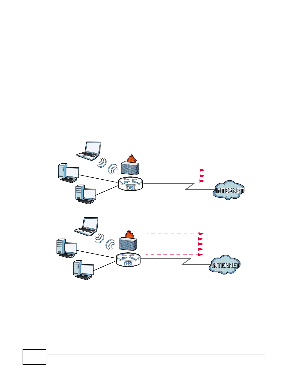
1.4.1 Internet Access
Your Device provides shared Internet access by connecting the DSL port to the DSL or MODEM
jack on a splitter or your telephone jack. You can have multiple WAN services over one ADSL or
VDSL. The Device cannot work in ADSL and VDSL mode at the same time.
Note: The ADSL and VDSL lines share the same WAN (layer-2) interfaces that you
configure in the Device. Refer to Section 5.2 on page 42 for the Network Setting
> Broadband screen.
Computers can connect to the Device’s LAN ports (or wirelessly).
Figure 1 Device’s Internet Access Application
18
You can also configure IP filtering on the Device for secure Internet access. When the IP filter is on,
all incoming traffic from the Internet to your network is blocked by default unless it is initiated from
your network. This means that probes from the outside to your network are not allowed, but you
can safely browse the Internet and download files.
VMG1312-B10C User’s Guide
1.4.2 Device’s USB Support
B
A
B
A
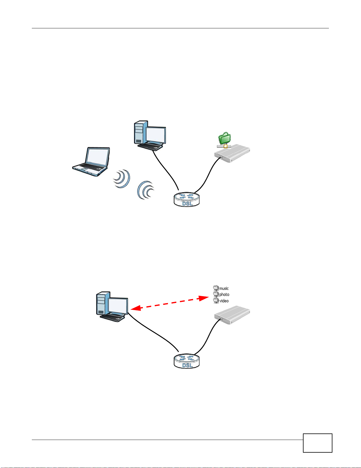
The USB port of the Device is used for file-sharing.
File Sharing
Use the built-in USB 2.0 port to share files on a USB memory stick or a USB hard drive (B). You can
connect one USB hard drive to the Device at a time. Use FTP to access the files on the USB device.
Figure 2 USB File Sharing Application
Chapter 1 Introducing the Device
Media Server
You can also use the Device as a media server. This lets anyone on your network play video, music,
and photos from a USB device (B) connected to the Device’s USB port (without having to copy them
to another computer).
Figure 3 USB Media Server Application
VMG1312-B10C User’s Guide
19
Chapter 1 Introducing the Device
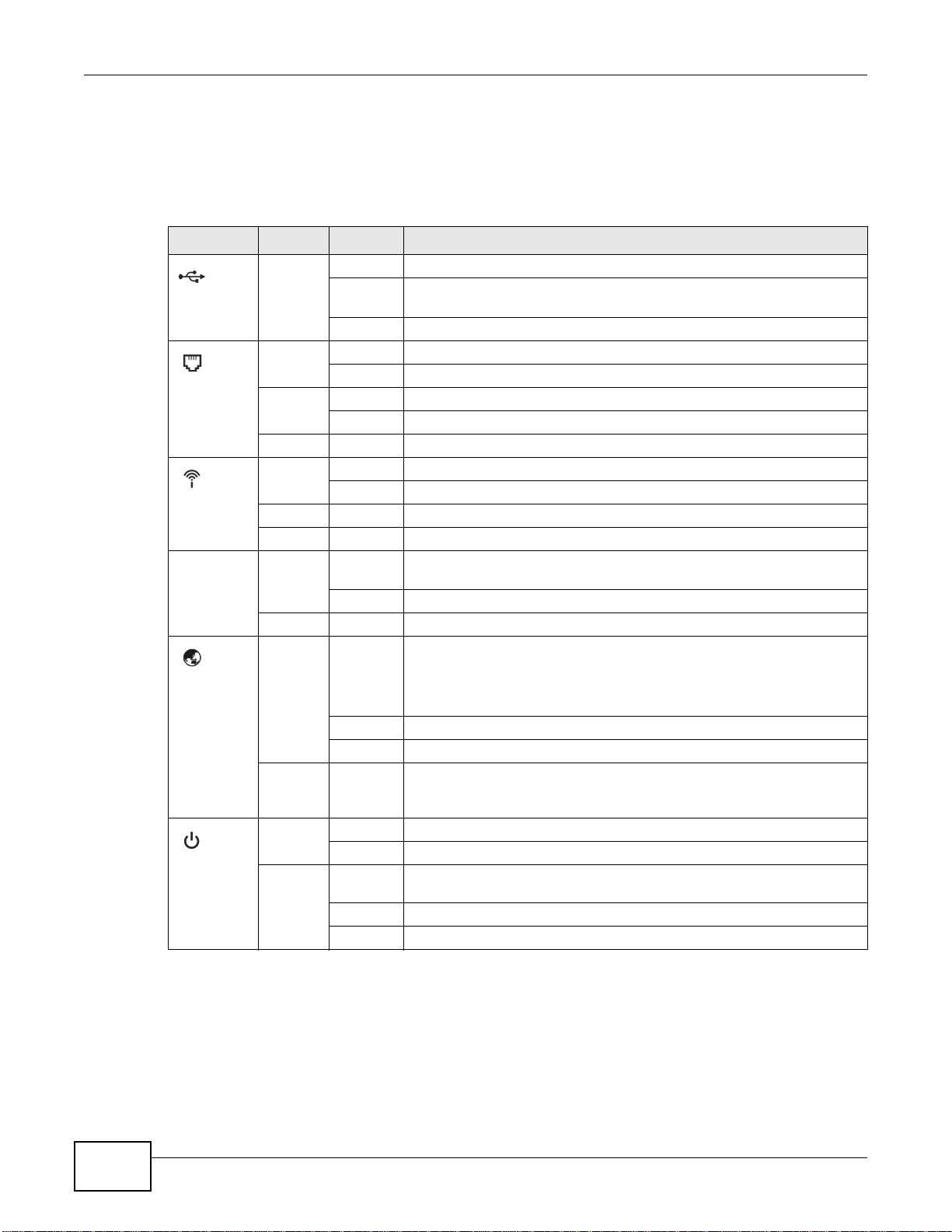
1.5 LEDs (Lights)
The following table describes the behavior of the LEDs. None of the LEDs are on if the Device is not
receiving power.
Table 1 LED Descriptions
LED COLOR STATUS DESCRIPTION
Green On The Device recognizes a USB connection.
USB
Green On The ADSL line is up.
DSL
WLAN/WPS
4~1
ETHERNET
Orange On The VDSL line is up.
Green On The wireless network is activated.
Orange Blinking The Device is setting up a WPS connection.
Green On The Device has a successful 100 Mbps Ethernet connection with a device
Green On The Device has an IP connection but no traffic.
Blinking The Device is sending/receiving data to /from the USB device connected
to it.
Off The Device does not detect a USB connection.
Blinking The Device is initializing the ADSL line.
Blinking The Device is initializing the VDSL line.
Off The DSL line is down.
Blinking The Device is communicating with other wireless clients.
Off The wireless network is not activated.
on the Local Area Network (LAN).
Blinking The Device is sending or receiving data to/from the LAN at 100 Mbps.
Off The Device does not have an Ethernet connection with the LAN.
INTERNET
Blinking The Device is sending or receiving IP traffic.
Off There is no Internet connection or the gateway is in bridged mode.
Red On The Device attempted to make an IP connection but failed. Possible
Green On The Device is receiving power and ready for use.
Blinking The Device is self-testing.
POWER
Red On The Device detected an error while self-testing, or there is a device
Off The Device is not receiving power.
Blinking Firmware upgrade is in progress.
1.6 The RESET Button
If you forget your password or cannot access the web configurator, you will need to use the RESET
button at the back of the device to reload the factory-default configuration file. This means that you
will lose all configurations that you had previously and the password will be reset to “1234”.
Your device has a WAN IP address (either static or assigned by a DHCP
server), PPP negotiation was successfully completed (if used) and the
DSL connection is up.
causes are no response from a DHCP server, no PPPoE response, PPPoE
authentication failed.
malfunction.
20
VMG1312-B10C User’s Guide
1 Make sure the POWER LED is on (not blinking).
2 To set the device back to the factory default settings, press the RESET button for ten seconds or
until the POWER LED begins to blink and then release it. When the POWER LED begins to blink,
the defaults have been restored and the device restarts.
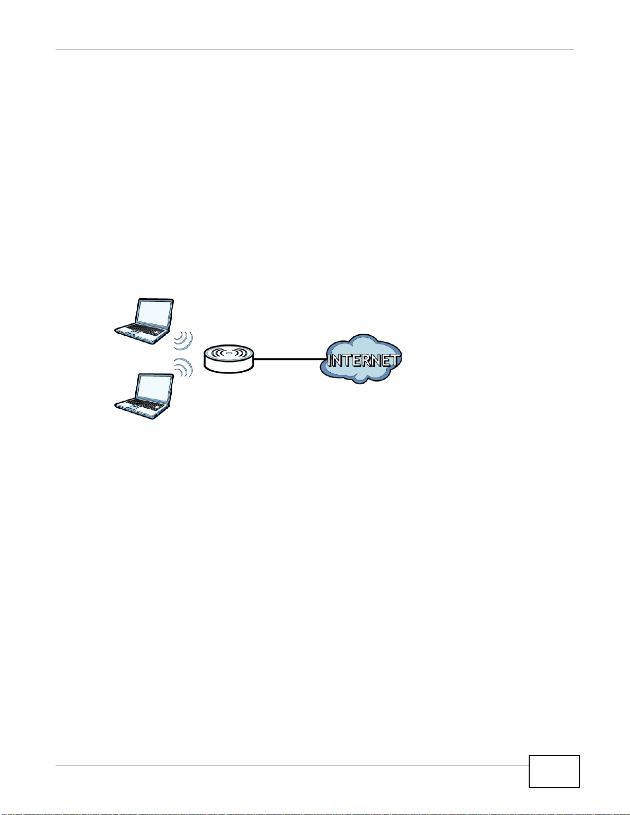
1.7 Wireless Access
The Device is a wireless Access Point (AP) for wireless clients, such as notebook computers or
tablets. It allows them to connect to the Internet without having to rely on inconvenient Ethernet
cables.
You can configure your wireless network in either the built-in Web Configurator, or using the WPS
button.
Figure 4 Wireless Access Example
Chapter 1 Introducing the Device
1.7.1 Using the WLAN/WPS Button
If the wireless network is turned off, press the WLAN/WPS button at the back of the Device for
one second. Once the WLAN/WPS LED turns green, the wireless network is active.
You can also use the WLAN/WPS button to quickly set up a secure wireless connection between
the Device and a WPS-compatible client by adding one device at a time.
To activate WPS:
1 Make sure the POWER LED is on and not blinking.
2 Press the WLAN/WPS button for five seconds and release it.
3 Press the WPS button on another WPS-enabled device within range of the Device. The WLAN/WPS
LED flashes orange while the Device sets up a WPS connection with the other wireless device.
4 Once the connection is successfully made, the WLAN/WPS LED shines green.
To turn off the wireless network, press the WLAN/WPS button on the front of the Device for one
second. The WLAN/WPS LED turns off when the wireless network is off.
VMG1312-B10C User’s Guide
21

Chapter 1 Introducing the Device
22
VMG1312-B10C User’s Guide
2.1 Overview
The web configurator is an HTML-based management interface that allows easy device setup and
management via Internet browser. Use Internet Explorer 6.0 and later versions or Mozilla Firefox 3
and later versions or Safari 2.0 and later versions. The recommended screen resolution is 1024 by
768 pixels.
In order to use the web configurator you need to allow:
• Web browser pop-up windows from your device. Web pop-up blocking is enabled by default in
Windows XP SP (Service Pack) 2.
• JavaScript (enabled by default).
• Java permissions (enabled by default).
CHAPTER 2
The Web Configurator
2.1.1 Accessing the Web Configurator
1 Make sure your Device hardware is properly connected (refer to the Quick Start Guide).
2 Launch your web browser. If the Device does not automatically re-direct you to the login screen, go
to http://192.168.1.1.
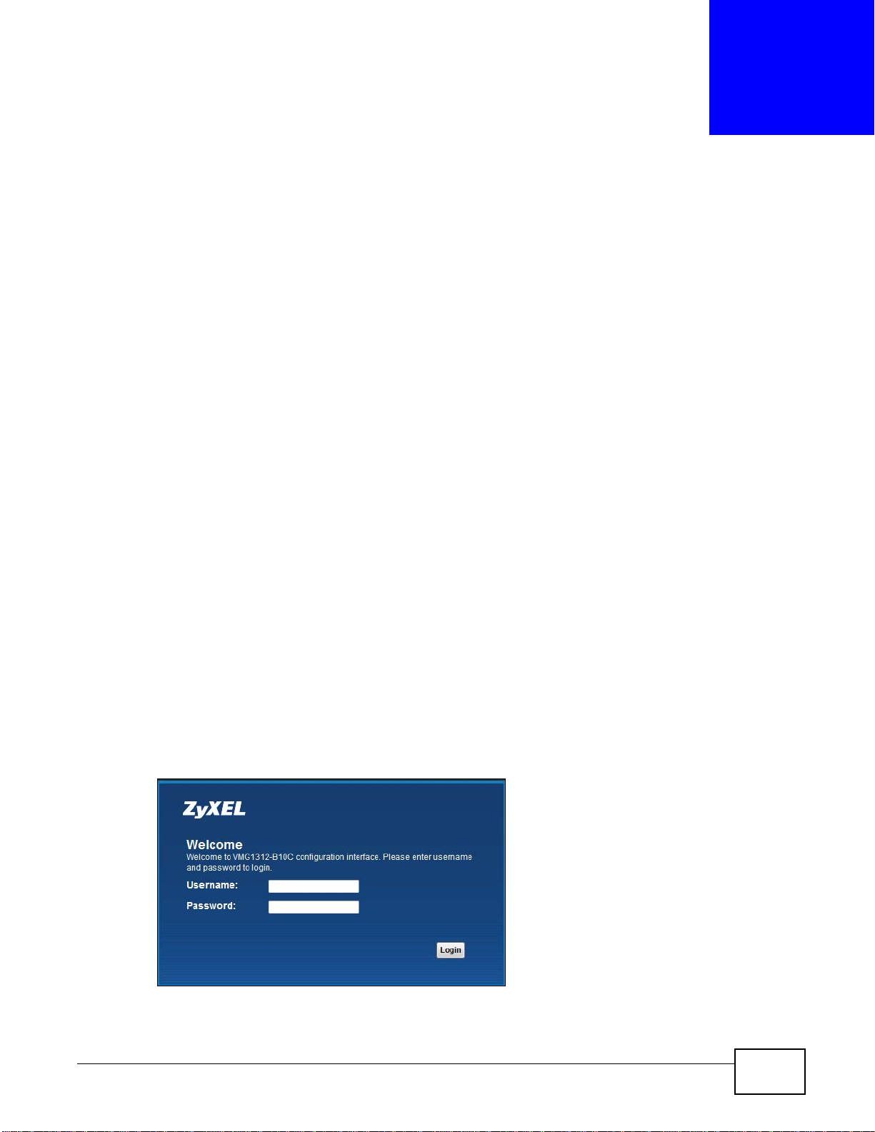
3 A password screen displays. To access the administrative web configurator and manage the Device,
type the default username admin and password 1234 in the password screen and click Login. If
advanced account security is enabled (see Section 27.2 on page 241) the number of dots that
appears when you type the password changes randomly to prevent anyone watching the password
field from knowing the length of your password. If you have changed the password, enter your
password and click Login.
Figure 5 Password Screen
VMG1312-B10C User’s Guide 23
Chapter 2 The Web Configurator
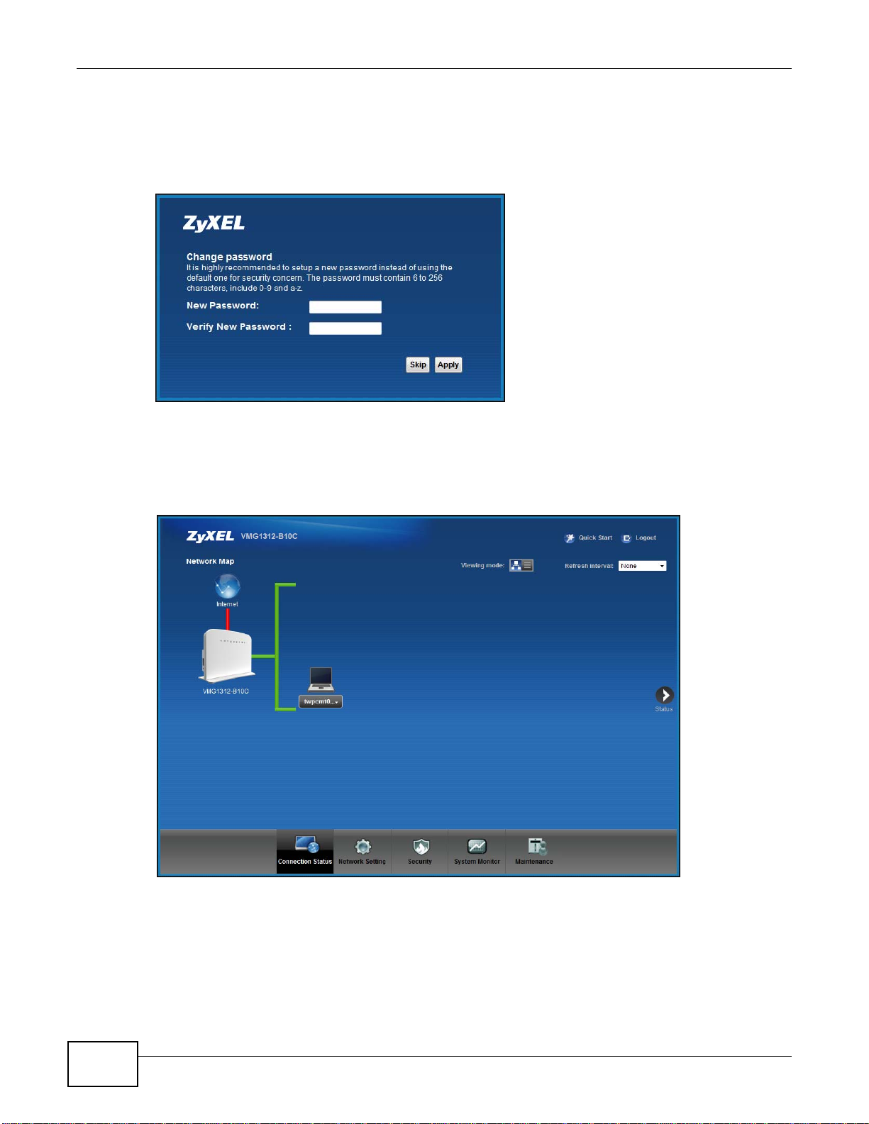
4 The following screen displays if you have not yet changed your password. It is strongly
recommended you change the default password. Enter a new password, retype it to confirm and
click Apply; alternatively click Skip to proceed to the main menu if you do not want to change the
password now.
Figure 6 Change Password Screen
5 The Quick Start Wizard screen appears. You can configure the Device’s time zone, basic Internet
access, and wireless settings. See Chapter 3 on page 31 for more information.
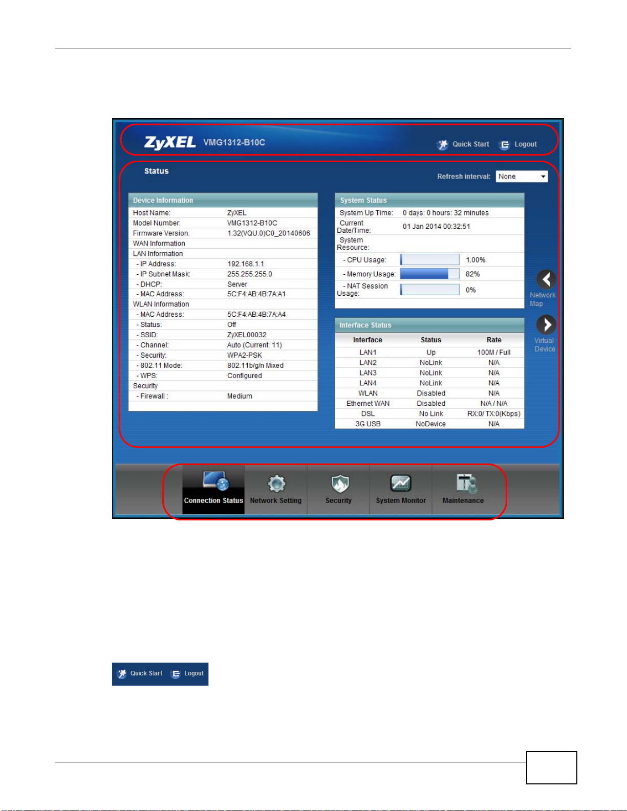
6 After you finished or closed the Quick Start Wizard screen, the Network Map page appears.
Figure 7 Network Map
7 Click Status to display the Status screen, where you can view the Device’s interface and system
information.
24
VMG1312-B10C User’s Guide
2.2 Web Configurator Layout
B
C
A
Figure 8 Screen Layout
Chapter 2 The Web Configurator
As illustrated above, the main screen is divided into these parts:
• A - title bar
• B - main window
• C - navigation panel
2.2.1 Title Bar
The title bar provides some icons in the upper right corner.
VMG1312-B10C User’s Guide
25

Chapter 2 The Web Configurator
The icons provide the following functions.
Table 2 Web Configurator Icons in the Title Bar
ICON DESCRIPTION
Quick Start Click this icon to open screens where you can configure the Device’s time zone Internet
Logout Click this icon to log out of the web configurator.
2.2.2 Main Window
The main window displays information and configuration fields. It is discussed in the rest of this
document.
After you click Status on the Connection Status page, the Status screen is displayed. See
Chapter 4 on page 36 for more information about the Status screen.
access, and wireless settings.
26
VMG1312-B10C User’s Guide
Chapter 2 The Web Configurator
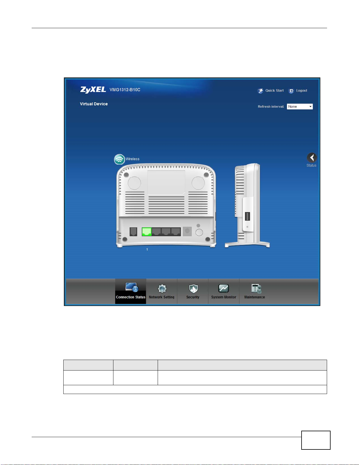
If you click Virtual Device on the System Info screen, a visual graphic appears, showing the
connection status of the Device’s ports. The connected ports are in color and disconnected ports are
gray.
Figure 9 Virtual Device
2.2.3 Navigation Panel
Use the menu items on the navigation panel to open screens to configure Device features. The
following tables describe each menu item.
Table 3 Navigation Panel Summary
LINK TAB FUNCTION
Connection Status This screen shows the network status of the Device and computers/
Network Setting
VMG1312-B10C User’s Guide
devices connected to it.
27

Chapter 2 The Web Configurator
Table 3 Navigation Panel Summary (continued)
LINK TAB FUNCTION
Broadband Broadband Use this screen to view and configure ISP parameters, WAN IP
Wireless General Use this screen to configure the wireless LAN settings and WLAN
Home
Networking
Routing Static Route Use this screen to view and set up static routes on the Device.
QoS General Use this screen to enable QoS and traffic prioritizing. You can also
address assignment, and other advanced properties. You can also add
new WAN connections.
3G Backup Use this screen to configure 3G WAN connection.
Advanced Use this screen to enable or disable PTM over ADSL, Annex M/Annex
8021x Use this screen to view and configure the IEEE 802.1x settings on the
Ethernet WAN Use this screen to configure a LAN port as an ethernet WAN port
More AP Use this screen to configure multiple BSSs on the Device.
MAC
Authentication
WPS Use this screen to configure and view your WPS (Wi-Fi Protected
WMM Use this screen to enable or disable Wi-Fi MultiMedia (WMM).
WDS Use this screen to set up Wireless Distribution System (WDS) links to
Others Use this screen to configure advanced wireless settings.
Channel Status Use this screen to scan wireless LAN channel noises and view the
LAN Setup Use this screen to configure LAN TCP/IP settings, and other advanced
Static DHCP Use this screen to assign specific IP addresses to individual MAC
UPnP Use this screen to turn UPnP and UPnP NAT-T on or off.
Additional
Subnet
STB Vendor ID Use this screen to have the Device automatically create static DHCP
LAN VLAN Use this screen to control the VLAN ID and IEEE 802.1p priority tags
Policy
Forwarding
RIP
Queue Setup Use this screen to configure QoS queues.
Class Setup Use this screen to define a classifier.
Policer Setup Use these screens to configure QoS policers.
Monitor Use this screen to view QoS packets statistics.
J, and DSL PhyR functions.
Device.
authentication/security settings.
Use this screen to block or allow wireless traffic from wireless devices
of certain SSIDs and MAC addresses to the Device.
Setup) settings.
other access points.
results.
properties.
addresses.
Use this screen to configure IP alias and public static IP.
entries for Set Top Box (STB) devices when they request IP
addresses.
of traffic sent out through individual LAN ports.
Use this screen to configure policy routing on the Device.
Use this screen to configure Routing Information Protocol to
exchange routing information with other routers.
configure the QoS rules and actions.
28
VMG1312-B10C User’s Guide

Chapter 2 The Web Configurator
Table 3 Navigation Panel Summary (continued)
LINK TAB FUNCTION
NAT Port Forwarding Use this screen to make your local servers visible to the outside
world.
Applications Use this screen to configure servers behind the Device.
Port Triggering Use this screen to change your Device’s port triggering settings.
DMZ Use this screen to configure a default server which receives packets
from ports that are not specified in the Port Forwarding screen.
ALG Use this screen to enable or disable SIP ALG.
Address Mapping Use this screen to change your Device’s address mapping settings.
DNS DNS Entry Use this screen to view and configure DNS routes.
Dynamic DNS Use this screen to allow a static hostname alias for a dynamic IP
Interface
Group
USB Device File Sharing Use this screen to enable file sharing via the Device.
Media Server Use this screen to use the Device as a media server.
Printer Server Use this screen to enable the print server on the Device and get the
Security Settings
Firewall General Use this screen to configure the security level of your firewall.
Service Use this screen to add Internet services and configure firewall rules.
Access Control Use this screen to enable specific traffic directions for network
DoS Use this screen to activate protection against Denial of Service (DoS)
MAC Filter Use this screen to block or allow traffic from devices of certain MAC
Parental
Control
Scheduler Rule Use this screen to configure the days and times when a configured
Certificates Local Certificates Use this screen to view a summary list of certificates and manage
Trusted CA
IPSec VPN Use this screen to add or edit VPN policies.
System Monitor
Log System Log Use this screen to view the status of events that occurred to the
Security Log Use this screen to view the login record of the Device. You can export
Traffic Status WAN Use this screen to view the status of all network traffic going through
LAN Use this screen to view the status of all network traffic going through
NAT Use this screen to view NAT statistics for connected hosts.
ARP Table Use this screen to view the ARP table. It displays the IP and MAC
address.
Use this screen to map a port to a PVC or bridge group.
model name of the associated printer.
services.
attacks.
addresses to the Device.
Use this screen to block web sites with the specific URL.
restriction (such as parental control) is enforced.
certificates and certification requests.
Use this screen to view and manage the list of the trusted CAs.
Device. You can export or e-mail the logs.
or e-mail the logs.
the WAN port of the Device.
the LAN ports of the Device.
address of each DHCP connection.
VMG1312-B10C User’s Guide
29

Chapter 2 The Web Configurator
Table 3 Navigation Panel Summary (continued)
LINK TAB FUNCTION
IGMP Group
Status
xDSL Statistics Use this screen to view the Device’s xDSL traffic statistics.
3G Monitor Use this screen to look at 3G Internet connection status.
Maintenance
User Account Use this screen to change user password on the Device.
Remote MGMT Use this screen to enable specific traffic directions for network
TR-069 Client Use this screen to configure the Device to be managed by an Auto
TR-064 Client Use this screen to enable management via TR-064 on the LAN.
Time Use this screen to change your Device’s time and date.
Email
Notification
Log Setting Use this screen to change your Device’s log settings.
Firmware
Upgrade
Configuration Use this screen to backup and restore your device’s configuration
Reboot Use this screen to reboot the Device without turning the power off.
Diagnostic Ping &
Use this screen to view the status of all IGMP settings on the Device.
services.
Configuration Server (ACS).
Use this screen to configure up to two mail servers and sender
addresses on the Device.
Use this screen to upload firmware to your device.
(settings) or reset the factory default settings.
Use this screen to identify problems with the DSL connection. You can
Tracerou t e &
Nslookup
802.1ag Use this screen to configure CFM (Connectivity Fault Management)
OAM Ping Use this screen to view information to help you identify problems with
use Ping, TraceRoute, or Nslookup to help you identify problems.
MD (maintenance domain) and MA (maintenance association),
perform connectivity tests and view test reports.
the DSL connection.
30
VMG1312-B10C User’s Guide

3.1 Overview
Use the Quick Start screens to configure the Device’s time zone, basic Internet access, and wireless
settings.
Note: See the technical reference chapters (starting on page 33) for background
information on the features in this chapter.
3.2 Quick Start Setup
1 The Quick Start Wizard appears automatically after login. Or you can click the Click Start icon in
the top right corner of the web configurator to open the quick start screens. Select the time zone of
the Device’s location and click Next.
Figure 10 Time Zone
CHAPTER 3
Quick Start
VMG1312-B10C User’s Guide 31

Chapter 3 Quick Start
2 Enter your Internet connection information in this screen. The screen and fields to enter may vary
depending on your current connection type. Click Next. Click Next.
Figure 11 Internet Connection
3 Turn the wireless LAN on or off. If you keep it on, record the security settings so you can configure
your wireless clients to connect to the Device. Click Save.
Figure 12 Internet Connection
4 Your Device saves your settings and attempts to connect to the Internet.
32
VMG1312-B10C User’s Guide

PART II
Technical Reference
33

34

Network Map and Status Screens
4.1 Overview
After you log into the Web Configurator, the Network Map screen appears. This shows the network
connection status of the Device and clients connected to it.
You can use the Status screen to look at the current status of the Device, system resources, and
interfaces (LAN, WAN, and WLAN).
4.2 The Network Map Screen
Use this screen to view the network connection status of the device and its clients. A warning
message appears if there is a connection problem.
CHAPTER 4
If you prefer to view the status in a list, click List View in the Viewing Mode selection box. You
can configure how often you want the Device to update this screen in Refresh Interval.
Figure 13 Network Map: Icon Mode
Figure 14 Network Map: List Mode
VMG1312-B10C User’s Guide 35

Chapter 4 Network Map and Status Screens
In Icon Mode, if you want to view information about a client, click the client’s name and Info.
Click the IP address if you want to change it. If you want to change the name or icon of the client,
click Change icon/name.
In List Mode, you can also view the client’s information.
4.3 The Status Screen
Use this screen to view the status of the Device. Click Status to open this screen.
Figure 15 Status Screen
36
VMG1312-B10C User’s Guide

Chapter 4 Network Map and Status Screens
Each field is described in the following table.
Table 4 Status Screen
LABEL DESCRIPTION
Refresh Interval Select how often you want the Device to update this screen.
Device Information
Host Name This field displays the Device system name. It is used for identification.
Model
Number
Firmware
Version
WAN Information (These fields display when you have a WAN connection.)
WAN Type This field displays the current WAN connection type.
MAC Address This shows the WAN Ethernet adapter MAC (Media Access Control) Address of your Device.
IP Address This field displays the current IP address of the Device in the WAN. Click Release to release
IP Subnet Mask This field displays the current subnet mask in the WAN.
Encapsulation This field displays the current encapsulation method.
LAN Information
IP Address This is the current IP address of the Device in the LAN.
IP Subnet
Mask
DHCP This field displays what DHCP services the Device is providing to the LAN. Choices are:
MAC
Address
WLAN Information
MAC
Address
Status This displays whether WLAN is activated.
SSID This is the descriptive name used to identify the Device in a wireless LAN.
Channel This is the channel number used by the Device now.
Security This displays the type of security mode the Device is using in the wireless LAN.
802.11
Mode
WPS This displays whether WPS is activated.
Security
Firewall This displays the firewall’s current security level.
System Status
System Up
Time
Current
Date/Time
This shows the model number of your Device.
This is the current version of the firmware inside the Device.
your IP address to 0.0.0.0. If you want to renew your IP address, click Renew.
This is the current subnet mask in the LAN.
Server - The Device is a DHCP server in the LAN. It assigns IP addresses to other
computers in the LAN.
Relay - The Device acts as a surrogate DHCP server and relays DHCP requests and
responses between the remote server and the clients.
None - The Device is not providing any DHCP services to the LAN.
This shows the LAN Ethernet adapter MAC (Media Access Control) Address of your Device.
This shows the wireless adapter MAC (Media Access Control) Address of your Device.
This displays the type of 802.11 mode the Device is using in the wireless LAN.
This field displays how long the Device has been running since it last started up. The Device
starts up when you plug it in, when you restart it (Maintenance > Reboot), or when you
reset it.
This field displays the current date and time in the Device. You can change this in
Maintenance> Time Setting.
VMG1312-B10C User’s Guide
37

Chapter 4 Network Map and Status Screens
Table 4 Status Screen (continued)
LABEL DESCRIPTION
System Resource
CPU Usage This field displays what percentage of the Device’s processing ability is currently used. When
this percentage is close to 100%, the Device is running at full load, and the throughput is
not going to improve anymore. If you want some applications to have more throughput, you
should turn off other applications (for example, using QoS; see Chapter 9 on page 131).
Memory
Usage
This field displays what percentage of the Device’s memory is currently used. Usually, this
percentage should not increase much. If memory usage does get close to 100%, the Device
is probably becoming unstable, and you should restart the device. See Section 35.2 on page
261, or turn off the device (unplug the power) for a few seconds.
38
VMG1312-B10C User’s Guide

5.1 Overview
WAN
This chapter discusses the Device’s Broadband screens. Use these screens to configure your
Device for Internet access.
A WAN (Wide Area Network) connection is an outside connection to another network or the
Internet. It connects your private networks, such as a LAN (Local Area Network) and other
networks, so that a computer in one location can communicate with computers in other locations.
Figure 16 LAN and WAN
CHAPTER 5
Broadband
3G (third generation) standards for the sending and receiving of voice, video, and data in a mobile
environment.
You can attach a 3G wireless adapter to the USB port and set the Device to use this 3G connection
as your WAN or a backup when the wired WAN connection fails.
Figure 17 3G WAN Connection
5.1.1 What You Can Do in this Chapter
•Use the Broadband screen to view, remove or add a WAN interface. You can also configure the
WAN settings on the Device for Internet access (Section 5.2 on page 42).
•Use the 3G Backup screen to configure 3G WAN connection (Section 5.3 on page 51).
VMG1312-B10C User’s Guide 39

Chapter 5 Broadband
•Use the Advanced screen to enable or disable PTM over ADSL, Annex M/Annex J, and DSL PhyR
functions (Section 5.4 on page 55).
•Use the 8021x screen to view and configure the IEEE 802.1X settings on the Device (Section 5.5
on page 56).
Table 5 WAN Setup Overview
LAYER-2 INTERFACE INTERNET CONNECTION
CONNECTION
ADSL/VDSL
over PTM
ADSL over ATM EoA Routing PPPoE/PPP0A ATM PVC configuration, PPP
EtherWAN N/A Routing PPPoE PPP user name and password, WAN
DSL LINK
TYPE
N/A Routing PPPoE PPP information, IPv4/IPv6 IP address,
MODE ENCAPSULATION CONNECTION SETTINGS
routing feature, DNS server, VLAN,
QoS, and MTU
IPoE IPv4/IPv6 IP address, routing feature,
DNS server, VLAN, QoS, and MTU
Bridge N/A VLAN and QoS
information, IPv4/IPv6 IP address,
routing feature, DNS server, VLAN,
QoS, and MTU
IPoE/IPoA ATM PVC configuration, IPv4/IPv6 IP
address, routing feature, DNS server,
VLAN, QoS, and MTU
Bridge N/A ATM PVC configuration, and QoS
IPv4/IPv6 IP address, routing feature,
DNS server, VLAN, QoS, and MTU
IPoE WAN IPv4/IPv6 IP address, NAT, DNS
server and routing feature
Bridge N/A VLAN and QoS
5.1.2 What You Need to Know
The following terms and concepts may help as you read this chapter.
Encapsulation Method
Encapsulation is used to include data from an upper layer protocol into a lower layer protocol. To set
up a WAN connection to the Internet, you need to use the same encapsulation method used by your
ISP (Internet Service Provider). If your ISP offers a dial-up Internet connection using PPPoE (PPP
over Ethernet), they should also provide a username and password (and service name) for user
authentication.
WAN IP Address
The WAN IP address is an IP address for the Device, which makes it accessible from an outside
network. It is used by the Device to communicate with other devices in other networks. It can be
static (fixed) or dynamically assigned by the ISP each time the Device tries to access the Internet.
If your ISP assigns you a static WAN IP address, they should also assign you the subnet mask and
DNS server IP address(es).
40
VMG1312-B10C User’s Guide

Chapter 5 Broadband
ATM
Asynchronous Transfer Mode (ATM) is a WAN networking technology that provides high-speed data
transfer. ATM uses fixed-size packets of information called cells. With ATM, a high QoS (Quality of
Service) can be guaranteed. ATM uses a connection-oriented model and establishes a virtual circuit
(VC) between Finding Out More
PTM
Packet Transfer Mode (PTM) is packet-oriented and supported by the VDSL2 standard. In PTM,
packets are encapsulated directly in the High-level Data Link Control (HDLC) frames. It is designed
to provide a low-overhead, transparent way of transporting packets over DSL links, as an
alternative to ATM.
3G
3G (Third Generation) is a digital, packet-switched wireless technology. Bandwidth usage is
optimized as multiple users share the same channel and bandwidth is only allocated to users when
they send data. It allows fast transfer of voice and non-voice data and provides broadband Internet
access to mobile devices.
IPv6 Introduction
IPv6 (Internet Protocol version 6), is designed to enhance IP address size and features. The
increase in IPv6 address size to 128 bits (from the 32-bit IPv4 address) allows up to 3.4 x 10
addresses. The Device can use IPv4/IPv6 dual stack to connect to IPv4 and IPv6 networks, and
supports IPv6 rapid deployment (6RD).
38
IP
IPv6 Addressing
The 128-bit IPv6 address is written as eight 16-bit hexadecimal blocks separated by colons (:). This
is an example IPv6 address 2001:0db8:1a2b:0015:0000:0000:1a2f:0000.
IPv6 addresses can be abbreviated in two ways:
• Leading zeros in a block can be omitted. So
2001:0db8:1a2b:0015:0000:0000:1a2f:0000 can be written as
2001:db8:1a2b:15:0:0:1a2f:0.
• Any number of consecutive blocks of zeros can be replaced by a double colon. A double
colon can only appear once in an IPv6 address. So
2001:0db8:0000:0000:1a2f:0000:0000:0015 can be written as
2001:0db8::1a2f:0000:0000:0015, 2001:0db8:0000:0000:1a2f::0015,
2001:db8::1a2f:0:0:15 or 2001:db8:0:0:1a2f::15.
IPv6 Prefix and Prefix Length
Similar to an IPv4 subnet mask, IPv6 uses an address prefix to represent the network address. An
IPv6 prefix length specifies how many most significant bits (start from the left) in the address
VMG1312-B10C User’s Guide
41

Chapter 5 Broadband
compose the network address. The prefix length is written as “/x” where x is a number. For
example,
2001:db8:1a2b:15::1a2f:0/32
means that the first 32 bits (2001:db8) is the subnet prefix.
IPv6 Subnet Masking
Both an IPv6 address and IPv6 subnet mask compose of 128-bit binary digits, which are divided
into eight 16-bit blocks and written in hexadecimal notation. Hexadecimal uses four bits for each
character (1 ~ 10, A ~ F). Each block’s 16 bits are then represented by four hexadecimal
characters. For example, FFFF:FFFF:FFFF:FFFF:FC00:0000:0000:0000.
5.1.3 Before You Begin
You need to know your Internet access settings such as encapsulation and WAN IP address. Get this
information from your ISP.
5.2 The Broadband Screen
Use this screen to change your Device’s Internet access settings. Click Network Setting >
Broadband from the menu. The summary table shows you the configured WAN services
(connections) on the Device.
Figure 18 Network Setting > Broadband
The following table describes the labels in this screen.
Table 6 Network Setting > Broadband
LABEL DESCRIPTION
Add new WAN
Interface
# This is the index number of the entry.
Name This is the service name of the connection.
Type This shows whether it is an ATM, PTM, or Ethernet connection.
Mode This shows whether the connection is in routing or bridge mode.
Encapsulation This is the method of encapsulation used by this connection.
802.1p This indicates the 802.1p priority level assigned to traffic sent through this connection. This
802.1q This indicates the VLAN ID number assigned to traffic sent through this connection. This
Click this button to create a new connection.
displays N/A when there is no priority level assigned.
displays N/A when there is no VLAN ID number assigned.
42
VMG1312-B10C User’s Guide

Chapter 5 Broadband
Table 6 Network Setting > Broadband (continued)
LABEL DESCRIPTION
IGMP Proxy This shows whether the Device act as an IGMP proxy on this connection.
NAT This shows whether NAT is activated or not for this connection.
Default
Gateway
IPv6 This shows whether IPv6 is activated or not for this connection. IPv6 is not available when
MLD Proxy This shows whether Multicast Listener Discovery (MLD) is activated or not for this
Modify/Delete Click the Edit icon to configure the WAN connection.
This shows whether the Device use the WAN interface of this connection as the system
default gateway.
the connection uses the bridging service.
connection. MLD is not available when the connection uses the bridging service.
Click the Delete icon to remove the WAN connection.
VMG1312-B10C User’s Guide
43

Chapter 5 Broadband
5.2.1 Add/Edit Internet Connection
Click Add new WAN Interface in the Broadband screen or the Edit icon next to an existing WAN
interface to configure a WAN connection. The screen varies depending on the interface type, mode,
encapsulation, and IPv6/IPv4 mode you select.
5.2.1.1 Routing Mode
Use Routing mode if your ISP give you one IP address only and you want multiple computers to
share an Internet account.
The following example screen displays when you select the ADSL over ATM connection type,
Routing mode, and PPPoE encapsulation. The screen varies when you select other interface type,
encapsulation, and IPv6/IPv4 mode.
Figure 19 Routing Mode
44
The following table describes the labels in this screen.
Table 7 Routing Mode
LABEL DESCRIPTION
General
Active Select this to activate the WAN configuration settings.
Name Specify a descriptive name for this connection.
Type Select whether it is an ADSL/VDSL over PTM, ADSL over ATM connection or Ethernet.
Mode Select Routing if your ISP give you one IP address only and you want multiple computers to
share an Internet account.
VMG1312-B10C User’s Guide

Chapter 5 Broadband
Table 7 Routing Mode (continued)
LABEL DESCRIPTION
Encapsulation Select the method of encapsulation used by your ISP from the drop-down list box. This
option is available only when you select Routing in the Mode field.
The choices depend on the connection type you selected. If your connection type is ADSL/
VDSL over PTM, the choices are PPPoE and IPoE. If your connection type is ADSL over
ATM, the choices are PPPoE, PPPoA, IPoE and IPoA.
IPv6/IPv4 Mode Select IPv4 Only if you want the Device to run IPv4 only.
Select IPv6/IPv4 DualStack to allow the Device to run IPv4 and IPv6 at the same time.
Select IPv6 Only if you want the Device to run IPv6 only.
ATM PVC Configuration (These fields appear when the Type is set to ADSL over ATM.)
VPI The valid range for the VPI is 0 to 255. Enter the VPI assigned to you.
VCI The valid range for the VCI is 32 to 65535 (0 to 31 is reserved for local management of ATM
traffic). Enter the VCI assigned to you.
DSL Link Type This field is not editable. The selection depends on the setting in the Encapsulation field.
EoA (Ethernet over ATM) uses an Ethernet header in the packet, so that you can have
multiple services/connections over one PVC. You can set each connection to have its own
MAC address or all connections share one MAC address but use different VLAN IDs for
different services. EoA supports ENET ENCAP (IPoE), PPPoE and RFC1483/2684 bridging
encapsulation methods.
PPPoA (PPP over ATM) allows just one PPPoA connection over a PVC.
IPoA (IP over ATM) allows just one RFC 1483 routing connection over a PVC.
Encapsulation
Mode
Service
Category
Peak Cell Rate Divide the DSL line rate (bps) by 424 (the size of an ATM cell) to find the Peak Cell Rate
Sustainable
Cell Rate
Select the method of multiplexing used by your ISP from the drop-down list box. Choices
are:
• LLC/SNAP-BRIDGING: In LCC encapsulation, bridged PDUs are encapsulated by
identifying the type of the bridged media in the SNAP header. This is available only when
you select IPoE or PPPoE in the Select DSL Link Type field.
• VC/MUX: In VC multiplexing, each protocol is carried on a single ATM virtual circuit
(VC). To transport multiple protocols, the Device needs separate VCs. There is a binding
between a VC and the type of the network protocol carried on the VC. This reduces
payload overhead since there is no need to carry protocol information in each Protocol
Data Unit (PDU) payload.
• LLC/ENCAPSULATION: More than one protocol can be carried over the same VC. This
is available only when you select PPPoA in the Encapsulation field.
• LLC/SNAP-ROUTING: In LCC encapsulation, an IEEE 802.2 Logical Link Control (LLC)
header is prefixed to each routed PDU to identify the PDUs. The LCC header can be
followed by an IEEE 802.1a SubNetwork Attachment Point (SNAP) header. This is
available only when you select IPoA in the Encapsulation field.
Select UBR Without PCR or UBR With PCR for applications that are non-time sensitive,
such as e-mail.
Select CBR (Continuous Bit Rate) to specify fixed (always-on) bandwidth for voice or data
traffic.
Select Non Realtime VBR (non real-time Variable Bit Rate) for connections that do not
require closely controlled delay and delay variation.
Select Realtime VBR (real-time Variable Bit Rate) for applications with bursty connections
that require closely controlled delay and delay variation.
(PCR). This is the maximum rate at which the sender can send cells. Type the PCR here.This
field is not available when you select UBR Without PCR.
The Sustainable Cell Rate (SCR) sets the average cell rate (long-term) that can be
transmitted. Type the SCR, which must be less than the PCR. Note that system default is 0
cells/sec.
This field is available only when you select Non Realtime VBR or Realtime VBR.
VMG1312-B10C User’s Guide
45

Chapter 5 Broadband
Table 7 Routing Mode (continued)
LABEL DESCRIPTION
Maximum Burst
Size
PPP
Information
PPP User Name Enter the user name exactly as your ISP assigned. If assigned a name in the form
PPP Password Enter the password associated with the user name above.
PPP Auto
Connect
IDLE Timeout This value specifies the time in minutes that elapses before the router automatically
PPPoE Service
Name
PPPoE
Passthrough
IP Address This is available only when you select IPv4 Only or IPv6/IPv4 DualStack in the IPv6/
Obtain an IP
Address
Automatically
Static IP
Address
IP Address Enter the static IP address provided by your ISP.
Subnet
Mask
Gateway IP
Address
Routing Feature This is available only when you select IPv4 Only or IPv6/IPv4 DualStack in the IPv6/
NAT Enable Select this option to activate NAT on this connection.
IGMP Proxy
Enable
Apply as
Default
Gateway
DNS Server This is available only when you select IPv4 Only or IPv6/IPv4 DualStack in the IPv6/
Maximum Burst Size (MBS) refers to the maximum number of cells that can be sent at the
peak rate. Type the MBS, which is less than 65535.
This field is available only when you select Non Realtime VBR or Realtime VBR.
This is available only when you select PPPoE or PPPoA in the Mode field.
user@domain where domain identifies a service name, then enter both components exactly
as given.
Select this option if you do not want the connection to time out.
disconnects from the PPPoE server.
This field is not configurable if you select PPP Auto Connect.
Enter the name of your PPPoE service here.
This field is available when you select PPPoE encapsulation.
In addition to the Device’s built-in PPPoE client, you can enable PPPoE pass through to allow
up to ten hosts on the LAN to use PPPoE client software on their computers to connect to the
ISP via the Device. Each host can have a separate account and a public WAN IP address.
PPPoE pass through is an alternative to NAT for application where NAT is not appropriate.
Disable PPPoE pass through if you do not need to allow hosts on the LAN to use PPPoE client
software on their computers to connect to the ISP.
IPv4 Mode field.
A static IP address is a fixed IP that your ISP gives you. A dynamic IP address is not fixed;
the ISP assigns you a different one each time you connect to the Internet. Select this if you
have a dynamic IP address.
Select this option If the ISP assigned a fixed IP address.
Enter the subnet mask provided by your ISP.
Enter the gateway IP address provided by your ISP.
IPv4 Mode field.
Internet Group Multicast Protocol (IGMP) is a network-layer protocol used to establish
membership in a Multicast group - it is not used to carry user data.
Select this option to have the Device act as an IGMP proxy on this connection. This allows
the Device to get subscribing information and maintain a joined member list for each
multicast group. It can reduce multicast traffic significantly.
Select this option to have the Device use the WAN interface of this connection as the system
default gateway.
IPv4 Mode field.
46
VMG1312-B10C User’s Guide

Chapter 5 Broadband
Table 7 Routing Mode (continued)
LABEL DESCRIPTION
DNS Select Dynamic if you want the Device use the DNS server addresses assigned by your ISP.
Select Static if you want the Device use the DNS server addresses you configure manually.
DNS Server 1 Enter the first DNS server address assigned by the ISP.
DNS Server 2 Enter the second DNS server address assigned by the ISP.
WAN MAC Address
Factory
Default
Clone the
computer’s
MAC
address
Set WAN
MAC
Address
IPv6 Address This is available only when you select IPv6/IPv4 DualStack or IPv6 Only in the IPv6/
IPv6 Address Select Automatic if you want to have the Device use the IPv6 prefix from the connected
Select Factory Default to use the factory assigned default MAC address.
Select this option and enter the IP address of the computer on the LAN whose MAC you are
cloning. It is advisable to clone the MAC address from a computer on your LAN even if your
ISP does not presently require MAC address authentication.
Select this option and enter the MAC address you want to use.
IPv4 Mode field.
router’s Router Advertisement (RA) to generate an IPv6 address.
Select the Get IPv6 Address From DHCPv6 Server check box if you want to obtain an
IPv6 address from a DHCPv6 server. The IP address assigned by a DHCPv6 server has
priority over the IP address automatically generated by the Device using the IPv6 prefix
from an RA. This option is available only when you choose to get your IPv6 address
automatically.
Select Static if you have a fixed IPv6 address assigned by your ISP.
Select None to not assign any IPv6 address to this WAN connection.
WAN IPv6
Address
Prefix
Length
Next Hop Enter the IP address of the next-hop gateway. The gateway is a router or switch on the
IPv6 Routing
Feature
MLD Proxy
Enable
Apply as
Default
Gateway
IPv6 DNS
Server
IPv6 DNS Select Dynamic to have the Device get the IPv6 DNS server addresses from the ISP
IPv6 DNS
Server 1
IPv6 DNS
Server 2
Enter the IPv6 address assigned by your ISP.
Enter the address prefix length to specify how many most significant bits in an IPv6 address
compose the network address.
same segment as your Device's interface(s). The gateway helps forward packets to their
destinations.
You can enable IPv6 routing features in the following section.
Select this check box to have the Device act as an MLD proxy on this connection. This allows
the Device to get subscription information and maintain a joined member list for each
multicast group. It can reduce multicast traffic significantly.
Select this option to have the Device use the WAN interface of this connection as the system
default gateway.
Configure the IPv6 DNS server in the following section.
automatically.
Select Static to have the Device use the IPv6 DNS server addresses you configure
manually.
Enter the first IPv6 DNS server address assigned by the ISP.
Enter the second IPv6 DNS server address assigned by the ISP.
VMG1312-B10C User’s Guide
47

Chapter 5 Broadband
Table 7 Routing Mode (continued)
LABEL DESCRIPTION
VLAN These fields appear when the Type is set to ADSL/VDSL over PTM.
Active Select this option to add the VLAN tag (specified below) to the outgoing traffic through this
802.1p IEEE 802.1p defines up to 8 separate traffic types by inserting a tag into a MAC-layer frame
802.1q Type the VLAN ID number (from 1 to 4094) for traffic through this connection.
QoS
Rate Limit Enter the rate limit for the connection. This is the maximum transmission rate allowed for
MTU
MTU Size Enter the MTU (Maximum Transfer Unit) size for this traffic.
Apply Click Apply to save your changes back to the Device.
Cancel Click Cancel to exit this screen without saving.
5.2.1.2 Bridge Mode
connection.
that contains bits to define class of service.
Select the IEEE 802.1p priority level (from 0 to 7) to add to traffic through this connection.
The greater the number, the higher the priority level.
traffic on this connection.
Click the Add new WAN Interface in the Network Setting > Broadband screen or the Edit icon
next to the connection you want to configure. Select Bridge as the encapsulation mode. The screen
varies depending on the interface type you select.
If you select ADSL/VDSL over PTM as the interface type, the following screen appears.
Figure 20 Bridge Mode (ADSL/VDSL over PTM)
48
VMG1312-B10C User’s Guide

Chapter 5 Broadband
The following table describes the fields in this screen.
Table 8 Bridge Mode (ADSL/VDSL over PTM)
LABEL DESCRIPTION
General
Active Select this to activate the WAN configuration settings.
Name Enter a service name of the connection.
Type Select ADSL/VDSL over PTM as the interface that you want to configure. The Device uses
Mode Select Bridge when your ISP provides you more than one IP address and you want the
VLAN This section is available only when you select ADSL/VDSL over PTM in the Type field.
Active Select this to add the VLAN Tag (specified below) to the outgoing traffic through this
802.1p IEEE 802.1p defines up to 8 separate traffic types by inserting a tag into a MAC-layer frame
802.1q Type the VLAN ID number (from 0 to 4094) for traffic through this connection.
QoS
Rate Limit Enter the rate limit for the connection. This is the maximum transmission rate allowed for
Apply Click Apply to save your changes.
Cancel Click Cancel to exit this screen without saving.
the VDSL technology for data transmission over the DSL port.
connected computers to get individual IP address from ISP’s DHCP server directly. If you
select Bridge, you cannot use routing functions, such as QoS, Firewall, DHCP server and
NAT on traffic from the selected LAN port(s).
connection.
that contains bits to define class of service.
Select the IEEE 802.1p priority level (from 0 to 7) to add to traffic through this connection.
The greater the number, the higher the priority level.
traffic on this connection.
If you select ADSL over ATM as the interface type, the following screen appears.
Figure 21 Bridge Mode (ADSL over ATM)
VMG1312-B10C User’s Guide
49

Chapter 5 Broadband
The following table describes the fields in this screen.
Table 9 Bridge Mode (ADSL over ATM)
LABEL DESCRIPTION
General
Active Select this to activate the WAN configuration settings.
Name Enter a service name of the connection.
Type Select ADSL over ATM as the interface for which you want to configure here. The Device
Mode Select Bridge when your ISP provides you more than one IP address and you want the
ATM PVC Configuration (These fields appear when the Type is set to ADSL over ATM.)
VPI The valid range for the VPI is 0 to 255. Enter the VPI assigned to you.
VCI The valid range for the VCI is 32 to 65535 (0 to 31 is reserved for local management of ATM
DSL Link Type This field is not editable. The selection depends on the setting in the Encapsulation field.
uses the ADSL technology for data transmission over the DSL port.
connected computers to get individual IP address from ISP’s DHCP server directly. If you
select Bridge, you cannot use routing functions, such as QoS, Firewall, DHCP server and
NAT on traffic from the selected LAN port(s).
traffic). Enter the VCI assigned to you.
EoA (Ethernet over ATM) uses an Ethernet header in the packet, so that you can have
multiple services/connections over one PVC. You can set each connection to have its own
MAC address or all connections share one MAC address but use different VLAN IDs for
different services. EoA supports ENET ENCAP (IPoE), PPPoE and RFC1483/2684 bridging
encapsulation methods.
PPPoA (PPP over ATM) allows just one PPPoA connection over a PVC.
IPoA (IP over ATM) allows just one RFC 1483 routing connection over a PVC.
Encapsulation
Mode
Service
Category
Peak Cell Rate Divide the DSL line rate (bps) by 424 (the size of an ATM cell) to find the Peak Cell Rate
Select the method of multiplexing used by your ISP from the drop-down list box. Choices
are:
• LLC/SNAP-BRIDGING: In LCC encapsulation, bridged PDUs are encapsulated by
identifying the type of the bridged media in the SNAP header. This is available only when
you select IPoE or PPPoE in the Select DSL Link Type field.
• VC/MUX: In VC multiplexing, each protocol is carried on a single ATM virtual circuit
(VC). To transport multiple protocols, the Device needs separate VCs. There is a binding
between a VC and the type of the network protocol carried on the VC. This reduces
payload overhead since there is no need to carry protocol information in each Protocol
Data Unit (PDU) payload.
• LLC/ENCAPSULATION: More than one protocol can be carried over the same VC. This
is available only when you select PPPoA in the Encapsulation field.
• LLC/SNAP-ROUTING: In LCC encapsulation, an IEEE 802.2 Logical Link Control (LLC)
header is prefixed to each routed PDU to identify the PDUs. The LCC header can be
followed by an IEEE 802.1a SubNetwork Attachment Point (SNAP) header. This is
available only when you select IPoA in the Encapsulation field.
Select UBR Without PCR or UBR With PCR for applications that are non-time sensitive,
such as e-mail.
Select CBR (Continuous Bit Rate) to specify fixed (always-on) bandwidth for voice or data
traffic.
Select Non Realtime VBR (non real-time Variable Bit Rate) for connections that do not
require closely controlled delay and delay variation.
Select Realtime VBR (real-time Variable Bit Rate) for applications with bursty connections
that require closely controlled delay and delay variation.
(PCR). This is the maximum rate at which the sender can send cells. Type the PCR here.This
field is not available when you select UBR Without PCR.
50
VMG1312-B10C User’s Guide

Table 9 Bridge Mode (ADSL over ATM) (continued)
LABEL DESCRIPTION
Sustainable Cell
Rate
Maximum Burst
Size
QoS
Rate Limit Enter the rate limit for the connection. This is the maximum transmission rate allowed for
Apply Click Apply to save your changes.
Cancel Click Cancel to exit this screen without saving.
The Sustainable Cell Rate (SCR) sets the average cell rate (long-term) that can be
transmitted. Type the SCR, which must be less than the PCR. Note that system default is 0
cells/sec.
This field is available only when you select Non Realtime VBR or Realtime VBR.
Maximum Burst Size (MBS) refers to the maximum number of cells that can be sent at the
peak rate. Type the MBS, which is less than 65535.
This field is available only when you select Non Realtime VBR or Realtime VBR.
traffic on this connection.
5.3 The 3G Backup Screen
Chapter 5 Broadband
Use this screen to configure your 3G settings. Click Network Setting > Broadband > 3G
Backup.
VMG1312-B10C User’s Guide
51

Chapter 5 Broadband
Note: The actual data rate you obtain varies depending the 3G card you use, the signal
Figure 22 Network Setting > Broadband > 3G Backup
strength to the service provider’s base station, and so on.
The following table describes the labels in this screen.
Table 10 Network Setting > Broadband > 3G Backup
LABEL DESCRIPTION
General
3G Backup Select Enable to have the Device use the 3G connection as your WAN or a backup when the
wired WAN connection fails.
Ping Check Select Enable if you want the Device to ping check the connection status of your WAN. You
can configure the frequency of the ping check and number of consecutive failures before
triggering 3G backup.
Check Cycle Enter the frequency of the ping check in this field.
Consecutive
Fail
Ping Default
Gateway
Ping the Host Select this to have the Device ping the particular host name or IP address you typed in this
3G Connection Settings
Card
description
Enter how many consecutive failures are required before 3G backup is triggered.
Select this to have the Device ping the WAN interface’s default gateway IP address.
field.
This field displays the manufacturer and model name of your 3G card if you inserted one in
the Device. Otherwise, it displays N/A.
52
VMG1312-B10C User’s Guide

Chapter 5 Broadband
Table 10 Network Setting > Broadband > 3G Backup (continued)
LABEL DESCRIPTION
Username Type the user name (of up to 64 ASCII printable characters) given to you by your service
provider.
Password Type the password (of up to 64 ASCII printable characters) associated with the user name
above.
PIN A PIN (Personal Identification Number) code is a key to a 3G card. Without the PIN code,
Dial string Enter the phone number (dial string) used to dial up a connection to your service provider’s
APN Enter the APN (Access Point Name) provided by your service provider. Connections with
Connection Select Nailed UP if you do not want the connection to time out.
you cannot use the 3G card.
If your ISP enabled PIN code authentication, enter the 4-digit PIN code (0000 for example)
provided by your ISP. If you enter the PIN code incorrectly, the 3G card may be blocked by
your ISP and you cannot use the account to access the Internet.
If your ISP disabled PIN code authentication, leave this field blank.
base station. Your ISP should provide the phone number.
For example, *99# is the dial string to establish a GPRS or 3G connection in Taiwan.
different APNs may provide different services (such as Internet access or MMS (Multi-Media
Messaging Service)) and charge method.
You can enter up to 32 ASCII printable characters. Spaces are allowed.
Select on Demand if you do not want the connection up all the time and specify an idle
time-out in the Max Idle Timeout field.
Max Idle
Timeout
Obtain an IP
Address
Automatically
Use the
following static
IP address
IP Address Enter your WAN IP address in this field if you selected Use the following static IP
Obtain DNS
info
dynamically
Use the
following static
DNS IP address
Primary DNS
server
Secondary DNS
server
Advanced Click this to show the advanced 3G backup settings.
Budget Setup
Enable Budget
Control
Time Budget Select this and specify the amount of time (in hours) that the 3G connection can be used
This value specifies the time in minutes that elapses before the Device automatically
disconnects from the ISP.
Select this option If your ISP did not assign you a fixed IP address.
Select this option If the ISP assigned a fixed IP address.
address.
Select this to have the Device get the DNS server addresses from the ISP automatically.
Select this to have the Device use the DNS server addresses you configure manually.
Enter the first DNS server address assigned by the ISP.
Enter the second DNS server address assigned by the ISP.
Select Enable to set a monthly limit for the user account of the installed 3G card. You can
set a limit on the total traffic and/or call time. The Device takes the actions you specified
when a limit is exceeded during the month.
within one month. If you change the value after you configure and enable budget control,
the Device resets the statistics.
VMG1312-B10C User’s Guide
53

Chapter 5 Broadband
Table 10 Network Setting > Broadband > 3G Backup (continued)
LABEL DESCRIPTION
Data Budget
(Mbytes)
Data Budget
(kPackets)
Reset all
budget
counters on
Reset time and
data budget
counters
Actions before
over budget
Enable % of
time budget/
data budget
(Mbytes)/data
budget
(kPackets)
Actions when
over budget
Current 3G
connection
Enable Email
Notification
Mail Server Select a mail server for the e-mail address specified below.
Over Budget
Email Title
Send
Notification to
Email
Interval Enter the interval of how many minutes you want the Device to e-mail you.
Enable Log Select this to activate the logging function at the interval you set in this field.
Basic Click this to hide the advanced settings of 3G backup.
Select this and specify how much downstream and/or upstream data (in Mega bytes) can be
transmitted via the 3G connection within one month.
Select Download/Upload to set a limit on the total traffic in both directions.
Select Download to set a limit on the downstream traffic (from the ISP to the Device).
Select Upload to set a limit on the upstream traffic (from the Device to the ISP).
If you change the value after you configure and enable budget control, the Device resets the
statistics.
Select this and specify how much downstream and/or upstream data (in k Packets) can be
transmitted via the 3G connection within one month.
Select Download/Upload to set a limit on the total traffic in both directions.
Select Download to set a limit on the downstream traffic (from the ISP to the Device).
Select Upload to set a limit on the upstream traffic (from the Device to the ISP).
If you change the value after you configure and enable budget control, the Device resets the
statistics.
Select the date on which the Device resets the budget every month. Select last if you want
the Device to reset the budget on the last day of the month. Select specific and enter the
number of the date you want the Device to reset the budget
Click this button to reset the time and data budgets immediately. The count starts over with
the 3G connection’s full configured monthly time and data budgets. This does not affect the
normal monthly budget restart; so if you configured the time and data budget counters to
reset on the second day of the month and you use this button on the first, the time and data
budget counters will still reset on the second.
Specify the actions the Device takes before the time or data limit exceeds.
Select Enable and enter a number from 1 to 99 in the percentage fields. If you change the
value after you configure and enable budget control, the Device resets the statistics.
Specify the actions the Device takes when the time or data limit is exceeded.
Select Keep to maintain an existing 3G connection or Drop to disconnect it.
Select this to enable the e-mail notification function. The Device will e-mail you a
notification when there over budget occurs.
If you do not select a mail server, e-mail notifications cannot be sent via e-mail. You must
have configured a mail server already in the Maintenance > Email Notification screen.
Type a title that you want to be in the subject line of the e-mail notifications that the Device
sends.
Notifications are sent to the e-mail address specified in this field. If this field is left blank,
notifications cannot be sent via e-mail.
54
VMG1312-B10C User’s Guide

Table 10 Network Setting > Broadband > 3G Backup (continued)
LABEL DESCRIPTION
Apply Click Apply to save your changes back to the Device.
Cancel Click Cancel to return to the previous configuration.
5.4 The Advanced Screen
Use the Advanced screen to enable or disable PTM over ADSL, Annex M, and DSL PhyR functions.
The Device supports the PhyR retransmission scheme. PhyR is a retransmission scheme designed to
provide protection against noise on the DSL line. It improves voice, video and data transmission
resilience by utilizing a retransmission buffer.
Click Network Setting > Broadband > Advanced to display the following screen.
Figure 23 Network Setting > Broadband > Advanced
Chapter 5 Broadband
The following table describes the labels in this screen.
Table 11 Network Setting > Network Setting > Broadband
LABEL DESCRIPTION
PTM over ADSL Select Enable to use PTM over ADSL. Since PTM has less overhead than ATM, some ISPs
Annex M You can enable Annex M for the Device to use double upstream mode to increase the
PhyR US Enable or disable PhyR US (upstream) for upstream transmission to the WAN. PhyR US
PhyR DS Enable or disable PhyR DS (downstream) for downstream transmission from the WAN.
Apply Click Apply to save your changes back to the Device.
Cancel Click Cancel to return to the previous configuration.
use PTM over ADSL for better performance.
maximum upstream transfer rate.
should be enabled if data being transmitted upstream is sensitive to noise. However,
enabling PhyR US can decrease the US line rate. Enabling or disabling PhyR will require the
CPE to retrain. For PhyR to function, the DSLAM must also support PhyR and have it
enabled.
PhyR DS should be enabled if data being transmitted downstream is sensitive to noise.
However, enabling PhyR DS can decrease the DS line rate. Enabling or disabling PhyR will
require the CPE to retrain. For PhyR to function, the DSLAM must also support PhyR and
have it enabled.
VMG1312-B10C User’s Guide
55

Chapter 5 Broadband
5.5 The 8021x Screen
You can view and configure the 802.1X authentication settings in the 8021x screen. Click Network
Setting > Broadband > 8021x to display the following screen.
Figure 24 Network Setting > Broadband > 8021x
The following table describes the labels in this screen.
Table 12 Network Setting > Network Setting > 8021x
LABEL DESCRIPTION
# This is the index number of the entry.
Status This field displays whether the authentication is active or not. A yellow bulb signifies that
Interface This is the interface that uses the authentication. This displays N/A when there is no
EAP Identity This shows the EAP identity of the authentication. This displays N/A when there is no EAP
EAP method This shows the EAP method used in the authentication. This displays N/A when there is no
Bidirectional
Authentication
Certificate This shows the certificate used for this authentication. This displays N/A when there is no
Trusted CA This shows the Trusted CA used for this authentication. This displays N/A when there is no
Apply Click Apply to save your changes back to the Device.
Cancel Click Cancel to return to the previous configuration.
this authentication is active. A gray bulb signifies that this authentication is not active.
interface assigned.
identity assigned.
EAP method assigned.
This shows whether bidirectional authentication is allowed.
certificate assigned.
Trusted CA assigned.
56
VMG1312-B10C User’s Guide

5.5.1 Edit 802.1X Settings
Use this screen to edit 802.1X authentication settings. Click the Edit icon next to the rule you want
to edit. The screen shown next appears.
Figure 25 802.1x: Add/Edit
The following table describes the labels in this screen.
Chapter 5 Broadband
Table 13 802.1x: Add/Edit
LABEL DESCRIPTION
Active This field allows you to activate/deactivate the authentication.
Select this to enable the authentication. Clear this to disable this authentication without
having to delete the entry.
Interface This field displays where there is an interface available to select for the 802.1X
authentication settings. Select the interface to which to apply the 802.1X authentication
settings.
EAP Identity Enter the EAP identity of the authentication.
EAP method This is the EAP method used for this authentication.
Enable
Bidirectional
Authentication
Certificate Select the certificate you want to assign to the authentication. You need to import the
Trusted CA Select the Trusted CA you want to assign to the authentication. You need to import the
Apply Click Apply to save your changes.
Cancel Click Cancel to exit this screen without saving.
Select this to allow bidirectional authentication.
certificate in the Security > Certificates > Local Certificates screen.
certificate in the Security > Certificates > Trusted CA screen.
5.6 The Ethernet WAN Screen
If you are using an ethernet WAN connection, you can configure a LAN port as an ethernet WAN
port. Click Network Setting > Broadband > Ethernet WAN to open this screen.
Note: LAN port 4 can operate as an Ethernet WAN port.
VMG1312-B10C User’s Guide
57

Chapter 5 Broadband
Figure 26 Network Setting > Broadband > Ethernet WAN
The following table describes the fields in this screen.
Table 14 Network Setting > Broadband > Ethernet WAN
LABEL DESCRIPTION
State Select Enable to use the Ethernet LAN port as a WAN port on the Device.
Apply Click Apply to save your changes back to the Device.
Cancel
Click Cancel to exit this screen without saving.
5.7 Technical Reference
The following section contains additional technical information about the Device features described
in this chapter.
Encapsulation
Be sure to use the encapsulation method required by your ISP. The Device can work in bridge mode
or routing mode. When the Device is in routing mode, it supports the following methods.
IP over Ethernet
IP over Ethernet (IPoE) is an alternative to PPPoE. IP packets are being delivered across an
Ethernet network, without using PPP encapsulation. They are routed between the Ethernet interface
and the WAN interface and then formatted so that they can be understood in a bridged
environment. For instance, it encapsulates routed Ethernet frames into bridged Ethernet cells.
PPP over ATM (PPPoA)
PPPoA stands for Point to Point Protocol over ATM Adaptation Layer 5 (AAL5). A PPPoA connection
functions like a dial-up Internet connection. The Device encapsulates the PPP session based on
RFC1483 and sends it through an ATM PVC (Permanent Virtual Circuit) to the Internet Service
Provider’s (ISP) DSLAM (digital access multiplexer). Please refer to RFC 2364 for more information
on PPPoA. Refer to RFC 1661 for more information on PPP.
58
VMG1312-B10C User’s Guide

Chapter 5 Broadband
PPP over Ethernet (PPPoE)
Point-to-Point Protocol over Ethernet (PPPoE) provides access control and billing functionality in a
manner similar to dial-up services using PPP. PPPoE is an IETF standard (RFC 2516) specifying how
a personal computer (PC) interacts with a broadband modem (DSL, cable, wireless, etc.)
connection.
For the service provider, PPPoE offers an access and authentication method that works with existing
access control systems (for example RADIUS).
One of the benefits of PPPoE is the ability to let you access one of multiple network services, a
function known as dynamic service selection. This enables the service provider to easily create and
offer new IP services for individuals.
Operationally, PPPoE saves significant effort for both you and the ISP or carrier, as it requires no
specific configuration of the broadband modem at the customer site.
By implementing PPPoE directly on the Device (rather than individual computers), the computers on
the LAN do not need PPPoE software installed, since the Device does that part of the task.
Furthermore, with NAT, all of the LANs’ computers will have access.
RFC 1483
RFC 1483 describes two methods for Multiprotocol Encapsulation over ATM Adaptation Layer 5
(AAL5). The first method allows multiplexing of multiple protocols over a single ATM virtual circuit
(LLC-based multiplexing) and the second method assumes that each protocol is carried over a
separate ATM virtual circuit (VC-based multiplexing). Please refer to RFC 1483 for more detailed
information.
Multiplexing
There are two conventions to identify what protocols the virtual circuit (VC) is carrying. Be sure to
use the multiplexing method required by your ISP.
VC-based Multiplexing
In this case, by prior mutual agreement, each protocol is assigned to a specific virtual circuit; for
example, VC1 carries IP, etc. VC-based multiplexing may be dominant in environments where
dynamic creation of large numbers of ATM VCs is fast and economical.
LLC-based Multiplexing
In this case one VC carries multiple protocols with protocol identifying information being contained
in each packet header. Despite the extra bandwidth and processing overhead, this method may be
advantageous if it is not practical to have a separate VC for each carried protocol, for example, if
charging heavily depends on the number of simultaneous VCs.
T raffic Shaping
Traffic Shaping is an agreement between the carrier and the subscriber to regulate the average rate
and fluctuations of data transmission over an ATM network. This agreement helps eliminate
congestion, which is important for transmission of real time data such as audio and video
connections.
VMG1312-B10C User’s Guide
59
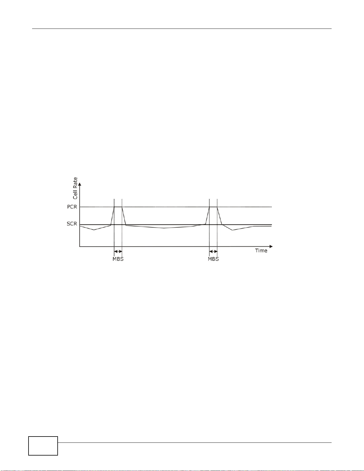
Chapter 5 Broadband
Peak Cell Rate (PCR) is the maximum rate at which the sender can send cells. This parameter may
be lower (but not higher) than the maximum line speed. 1 ATM cell is 53 bytes (424 bits), so a
maximum speed of 832Kbps gives a maximum PCR of 1962 cells/sec. This rate is not guaranteed
because it is dependent on the line speed.
Sustained Cell Rate (SCR) is the mean cell rate of each bursty traffic source. It specifies the
maximum average rate at which cells can be sent over the virtual connection. SCR may not be
greater than the PCR.
Maximum Burst Size (MBS) is the maximum number of cells that can be sent at the PCR. After MBS
is reached, cell rates fall below SCR until cell rate averages to the SCR again. At this time, more
cells (up to the MBS) can be sent at the PCR again.
If the PCR, SCR or MBS is set to the default of "0", the system will assign a maximum value that
correlates to your upstream line rate.
The following figure illustrates the relationship between PCR, SCR and MBS.
Figure 27 Example of Traffic Shaping
60
ATM Traffic Classes
These are the basic ATM traffic classes defined by the ATM Forum Traffic Management 4.0
Specification.
Constant Bit Rate (CBR)
Constant Bit Rate (CBR) provides fixed bandwidth that is always available even if no data is being
sent. CBR traffic is generally time-sensitive (doesn't tolerate delay). CBR is used for connections
that continuously require a specific amount of bandwidth. A PCR is specified and if traffic exceeds
this rate, cells may be dropped. Examples of connections that need CBR would be high-resolution
video and voice.
Variable Bit Rate (VBR)
The Variable Bit Rate (VBR) ATM traffic class is used with bursty connections. Connections that use
the Variable Bit Rate (VBR) traffic class can be grouped into real time (VBR-RT) or non-real time
(VBR-nRT) connections.
The VBR-RT (real-time Variable Bit Rate) type is used with bursty connections that require closely
controlled delay and delay variation. It also provides a fixed amount of bandwidth (a PCR is
VMG1312-B10C User’s Guide

Chapter 5 Broadband
specified) but is only available when data is being sent. An example of an VBR-RT connection would
be video conferencing. Video conferencing requires real-time data transfers and the bandwidth
requirement varies in proportion to the video image's changing dynamics.
The VBR-nRT (non real-time Variable Bit Rate) type is used with bursty connections that do not
require closely controlled delay and delay variation. It is commonly used for "bursty" traffic typical
on LANs. PCR and MBS define the burst levels, SCR defines the minimum level. An example of an
VBR-nRT connection would be non-time sensitive data file transfers.
Unspecified Bit Rate (UBR)
The Unspecified Bit Rate (UBR) ATM traffic class is for bursty data transfers. However, UBR doesn't
guarantee any bandwidth and only delivers traffic when the network has spare bandwidth. An
example application is background file transfer.
IP Address Assignment
A static IP is a fixed IP that your ISP gives you. A dynamic IP is not fixed; the ISP assigns you a
different one each time. The Single User Account feature can be enabled or disabled if you have
either a dynamic or static IP. However the encapsulation method assigned influences your choices
for IP address and default gateway.
Introduction to VLANs
A Virtual Local Area Network (VLAN) allows a physical network to be partitioned into multiple logical
networks. Devices on a logical network belong to one group. A device can belong to more than one
group. With VLAN, a device cannot directly talk to or hear from devices that are not in the same
group(s); the traffic must first go through a router.
In Multi-Tenant Unit (MTU) applications, VLAN is vital in providing isolation and security among the
subscribers. When properly configured, VLAN prevents one subscriber from accessing the network
resources of another on the same LAN, thus a user will not see the printers and hard disks of
another user in the same building.
VLAN also increases network performance by limiting broadcasts to a smaller and more
manageable logical broadcast domain. In traditional switched environments, all broadcast packets
go to each and every individual port. With VLAN, all broadcasts are confined to a specific broadcast
domain.
Introduction to IEEE 802.1Q Tagged VLAN
A tagged VLAN uses an explicit tag (VLAN ID) in the MAC header to identify the VLAN membership
of a frame across bridges - they are not confined to the switch on which they were created. The
VLANs can be created statically by hand or dynamically through GVRP. The VLAN ID associates a
frame with a specific VLAN and provides the information that switches need to process the frame
across the network. A tagged frame is four bytes longer than an untagged frame and contains two
bytes of TPID (Tag Protocol Identifier), residing within the type/length field of the Ethernet frame)
and two bytes of TCI (Tag Control Information), starts after the source address field of the Ethernet
frame).
The CFI (Canonical Format Indicator) is a single-bit flag, always set to zero for Ethernet switches. If
a frame received at an Ethernet port has a CFI set to 1, then that frame should not be forwarded as
it is to an untagged port. The remaining twelve bits define the VLAN ID, giving a possible maximum
VMG1312-B10C User’s Guide
61

Chapter 5 Broadband
number of 4,096 VLANs. Note that user priority and VLAN ID are independent of each other. A
frame with VID (VLAN Identifier) of null (0) is called a priority frame, meaning that only the priority
level is significant and the default VID of the ingress port is given as the VID of the frame. Of the
4096 possible VIDs, a VID of 0 is used to identify priority frames and value 4095 (FFF) is reserved,
so the maximum possible VLAN configurations are 4,094.
TPID
2 Bytes
User Priority
3 Bits
CFI
1 Bit
VLAN ID
12 Bits
Multicast
IP packets are transmitted in either one of two ways - Unicast (1 sender - 1 recipient) or Broadcast
(1 sender - everybody on the network). Multicast delivers IP packets to a group of hosts on the
network - not everybody and not just 1.
Internet Group Multicast Protocol (IGMP) is a network-layer protocol used to establish membership
in a Multicast group - it is not used to carry user data. IGMP version 2 (RFC 2236) is an
improvement over version 1 (RFC 1112) but IGMP version 1 is still in wide use. If you would like to
read more detailed information about interoperability between IGMP version 2 and version 1, please
see sections 4 and 5 of RFC 2236. The class D IP address is used to identify host groups and can be
in the range 224.0.0.0 to 239.255.255.255. The address 224.0.0.0 is not assigned to any group
and is used by IP multicast computers. The address 224.0.0.1 is used for query messages and is
assigned to the permanent group of all IP hosts (including gateways). All hosts must join the
224.0.0.1 group in order to participate in IGMP. The address 224.0.0.2 is assigned to the multicast
routers group.
At start up, the Device queries all directly connected networks to gather group membership. After
that, the Device periodically updates this information.
DNS Server Address Assignment
Use Domain Name System (DNS) to map a domain name to its corresponding IP address and vice
versa, for instance, the IP address of www.zyxel.com is 204.217.0.2. The DNS server is extremely
important because without it, you must know the IP address of a computer before you can access
it.
The Device can get the DNS server addresses in the following ways.
1 The ISP tells you the DNS server addresses, usually in the form of an information sheet, when you
sign up. If your ISP gives you DNS server addresses, manually enter them in the DNS server fields.
2 If your ISP dynamically assigns the DNS server IP addresses (along with the Device’s WAN IP
address), set the DNS server fields to get the DNS server address from the ISP.
IPv6 Addressing
The 128-bit IPv6 address is written as eight 16-bit hexadecimal blocks separated by colons (:). This
is an example IPv6 address 2001:0db8:1a2b:0015:0000:0000:1a2f:0000.
IPv6 addresses can be abbreviated in two ways:
62
VMG1312-B10C User’s Guide

Chapter 5 Broadband
• Leading zeros in a block can be omitted. So 2001:0db8:1a2b:0015:0000:0000:1a2f:0000 can
be written as 2001:db8:1a2b:15:0:0:1a2f:0.
• Any number of consecutive blocks of zeros can be replaced by a double colon. A double colon can
only appear once in an IPv6 address. So 2001:0db8:0000:0000:1a2f:0000:0000:0015 can be
written as 2001:0db8::1a2f:0000:0000:0015, 2001:0db8:0000:0000:1a2f::0015,
2001:db8::1a2f:0:0:15 or 2001:db8:0:0:1a2f::15.
IPv6 Prefix and Prefix Length
Similar to an IPv4 subnet mask, IPv6 uses an address prefix to represent the network address. An
IPv6 prefix length specifies how many most significant bits (start from the left) in the address
compose the network address. The prefix length is written as “/x” where x is a number. For
example,
2001:db8:1a2b:15::1a2f:0/32
means that the first 32 bits (2001:db8) is the subnet prefix.
VMG1312-B10C User’s Guide
63

Chapter 5 Broadband
64
VMG1312-B10C User’s Guide

6.1 Overview
This chapter describes the Device’s Network Setting > Wireless screens. Use these screens to
set up your Device’s wireless connection.
6.1.1 What You Can Do in this Chapter
This section describes the Device’s Wireless screens. Use these screens to set up your Device’s
wireless connection.
•Use the General screen to enable the Wireless LAN, enter the SSID and select the wireless
security mode (Section 6.2 on page 66).
•Use the More AP screen to set up multiple wireless networks on your Device (Section 6.3 on
page 75).
•Use the MAC Authentication screen to allow or deny wireless clients based on their MAC
addresses from connecting to the Device (Section 6.4 on page 78).
•Use the WPS screen to enable or disable WPS, view or generate a security PIN (Personal
Identification Number) (Section 6.5 on page 79).
•Use the WMM screen to enable Wi-Fi MultiMedia (WMM) to ensure quality of service in wireless
networks for multimedia applications (Section 6.6 on page 81).
•Use the WDS screen to set up a Wireless Distribution System, in which the Device acts as a
bridge with other ZyXEL access points (Section 6.7 on page 82).
•Use the Others screen to configure wireless advanced features, such as the RTS/CTS Threshold
(Section 6.8 on page 84).
•Use the Channel Status screen to scan wireless LAN channel noises and view the results
(Section 6.9 on page 86).
CHAPTER 6
Wireless
VMG1312-B10C User’s Guide 65

Chapter 6 Wireless
6.1.2 What You Need to Know
Wireless Basics
“Wireless” is essentially radio communication. In the same way that walkie-talkie radios send and
receive information over the airwaves, wireless networking devices exchange information with one
another. A wireless networking device is just like a radio that lets your computer exchange
information with radios attached to other computers. Like walkie-talkies, most wireless networking
devices operate at radio frequency bands that are open to the public and do not require a license to
use. However, wireless networking is different from that of most traditional radio communications in
that there a number of wireless networking standards available with different methods of data
encryption.
Finding Out More
See Section 6.10 on page 86 for advanced technical information on wireless networks.
6.2 The General Screen
Use this screen to enable the Wireless LAN, enter the SSID and select the wireless security mode.
Note: If you are configuring the Device from a computer connected to the wireless LAN
and you change the Device’s SSID, channel or security settings, you will lose your
wireless connection when you press Apply to confirm. You must then change the
wireless settings of your computer to match the Device’s new settings.
66
VMG1312-B10C User’s Guide

Click Network Setting > Wireless to open the General screen.
Figure 28 Network Setting > Wireless > General
Chapter 6 Wireless
VMG1312-B10C User’s Guide
67

Chapter 6 Wireless
The following table describes the general wireless LAN labels in this screen.
Table 15 Network Setting > Wireless > General
LABEL DESCRIPTION
Wireless Network Setup
Wireless You can Enable or Disable the wireless LAN in this field.
Band This shows the wireless band which this radio profile is using. 2.4GHz is the frequency used
Channel Set the channel depending on your particular region.
more.../less Click more... to show more information. Click less to hide them.
Bandwidth Select whether the Device uses a wireless channel width of 20MHz or 40MHz, or use Auto
Control
Sideband
Passphrase
Type
by IEEE 802.11b/g/n wireless clients.
Select a channel or use Auto to have the Device automatically determine a channel to use.
If you are having problems with wireless interference, changing the channel may help. Try
to use a channel that is as many channels away from any channels used by neighboring APs
as possible. The channel number which the Device is currently using then displays next to
this field.
to have the Device automatically select one.
A standard 20MHz channel offers transfer speeds of up to 150Mbps whereas a 40MHz
channel uses two standard channels and offers speeds of up to 300 Mbps.
40MHz (channel bonding or dual channel) bonds two adjacent radio channels to increase
throughput. The wireless clients must also support 40 MHz. It is often better to use the 20
MHz setting in a location where the environment hinders the wireless signal.
Select 20MHz if you want to lessen radio interference with other wireless devices in your
neighborhood or the wireless clients do not support channel bonding.
This is available for some regions when you select a specific channel and set the Bandwidth
field to 40MHz. Set whether the control channel (set in the Channel field) should be in the
Lower or Upper range of channel bands.
If you set security for the wireless LAN and have the Device generate a password, the
setting in this field determines how the Device generates the password.
Select None to set the Device’s password generation to not be based on a passphrase.
68
Select Fixed to use a 16 character passphrase for generating a password.
Select Variable to use a 16 to 63 character passphrase for generating a password.
Passphrase Key For a fixed type passphrase enter 16 alphanumeric characters (0-9, A-Z, with no spaces). It
must contain both letters and numbers and is case-sensitive.
For a variable type passphrase enter 16 to 63 alphanumeric characters (0-9, A-Z, with no
spaces). It must contain both letters and numbers and is case-sensitive.
Wireless Network Settings
Wireless
Network Name
(SSID)
Max clients Specify the maximum number of clients that can connect to this network at the same time.
Hide SSID Select this check box to hide the SSID in the outgoing beacon frame so a station cannot
Client Isolation Select this to keep the wireless clients in this SSID from communicating with each other
MBSSID/LAN
Isolation
The SSID (Service Set IDentity) identifies the service set with which a wireless device is
associated. Wireless devices associating to the access point (AP) must have the same SSID.
Enter a descriptive name (up to 32 English keyboard characters) for the wireless LAN.
obtain the SSID through scanning using a site survey tool.
through the Device.
Select this to keep the wireless clients in this SSID from communicating with clients in other
SSIDs or wired LAN devices through the Device.
Select both Client Isolation and MBSSID/LAN Isolation to allow this SSID’s wireless
clients to only connect to the Internet through the Device.
VMG1312-B10C User’s Guide

Chapter 6 Wireless
Table 15 Network Setting > Wireless > General (continued)
LABEL DESCRIPTION
Enhanced
Multicast
Forwarding
Maximum
Upstream
Bandwidth
Maximum
Downstream
Bandwidth
BSSID This shows the MAC address of the wireless interface on the Device when wireless LAN is
Security Level
Security Mode Select Basic (WEP, 802.1X) or More Secure (WPA(2)-PSK, WPA(2)) to add security
Apply Click Apply to save your changes.
Cancel Click Cancel to restore your previously saved settings.
Select this check box to allow the Device to convert wireless multicast traffic into wireless
unicast traffic.
Specify the maximum rate for upstream wireless traffic to the WAN from this WLAN in
kilobits per second (Kbps).
Specify the maximum rate for downstream wireless traffic to this WLAN from the WAN in
kilobits per second (Kbps).
enabled.
on this wireless network. The wireless clients which want to associate to this network must
have same wireless security settings as the Device. When you select to use a security,
additional options appears in this screen.
Or you can select No Security to allow any client to associate this network without any data
encryption or authentication.
See the following sections for more details about this field.
6.2.1 No Security
Select No Security to allow wireless stations to communicate with the access points without any
data encryption or authentication.
Note: If you do not enable any wireless security on your Device, your network is
accessible to any wireless networking device that is within range.
Figure 29 Wireless > General: No Security
The following table describes the labels in this screen.
Table 16 Wireless > General: No Security
LABEL DESCRIPTION
Security Level Choose No Security to allow all wireless connections without data encryption or
authentication.
VMG1312-B10C User’s Guide
69

Chapter 6 Wireless
6.2.2 Basic (WEP Encryption)
WEP encryption scrambles the data transmitted between the wireless stations and the access points
(AP) to keep network communications private. Both the wireless stations and the access points
must use the same WEP key.
Note: WEP is extremely insecure. Its encryption can be broken by an attacker, using
widely-available software. It is strongly recommended that you use a more
effective security mechanism. Use the strongest security mechanism that all the
wireless devices in your network support. For example, use WPA-PSK or WPA2-PSK
if all your wireless devices support it, or use WPA or WPA2 if your wireless devices
support it and you have a RADIUS server. If your wireless devices support nothing
stronger than WEP, use the highest encryption level available.
Your Device allows you to configure up to four 64-bit or 128-bit WEP keys but only one key can be
enabled at any one time.
In order to configure and enable WEP encryption, click Network Setting > Wireless to display the
General screen, then select Basic as the security level.
Figure 30 Wireless > General: Basic (WEP)
70
The following table describes the labels in this screen.
Table 17 Wireless > General: Basic (WEP)
LABEL DESCRIPTION
Security Level Select Basic to enable WEP data encryption.
Generate
password
automatically
Select this option to have the Device automatically generate a password. The password field
will not be configurable when you select this option.
VMG1312-B10C User’s Guide
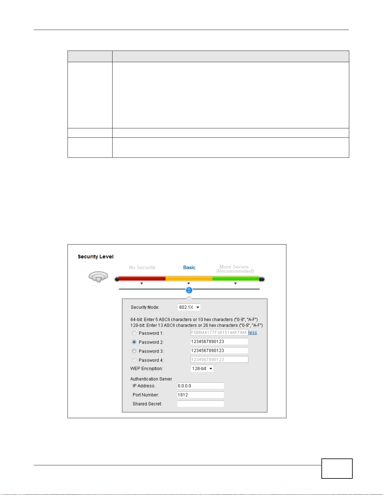
Table 17 Wireless > General: Basic (WEP) (continued)
LABEL DESCRIPTION
Password 1~4 The password (WEP keys) are used to encrypt data. Both the Device and the wireless
more.../less Click more... to show more fields in this section. Click less to hide them.
WEP Encryption Select 64-bits or 128-bits.
6.2.3 Basic (802.1X)
Use this screen to configure 802.1X encryption and authentication. Configure your RADIUS server
information and WEP encryption settings. Use this security method if your wireless usernames and
passwords are configured on a RADIUS server.
Chapter 6 Wireless
stations must use the same password (WEP key) for data transmission.
If you chose 64-bit WEP, then enter any 5 ASCII characters or 10 hexadecimal characters
("0-9", "A-F").
If you chose 128-bit WEP, then enter 13 ASCII characters or 26 hexadecimal characters
("0-9", "A-F").
You must configure at least one password, only one password can be activated at any one
time.
This dictates the length of the security key that the network is going to use.
In order to configure and enable WEP encryption, click Network Setting > Wireless to display the
General screen, then select Basic as the security level and 802.1X as the Security Mode.
Figure 31 Wireless > General: Basic (802.1X)
VMG1312-B10C User’s Guide
71

Chapter 6 Wireless
The following table describes the labels in this screen.
Table 18 Wireless > General: Basic (802.1X)
LABEL DESCRIPTION
Security Level Select Basic and 802.1X to enable 802.1X data encryption.
Generate
password
automatically
Password 1~4 The password (WEP key) is used to encrypt data. Both the Device and the wireless stations
more.../less Click more... to show more fields in this section. Click less to hide them.
WEP Encryption Select 64-bits or 128-bits.
IP Address Enter the IP address of an external RADIUS server in dotted decimal notation.
Port Number The default port of a RADIUS server for authentication is 1812. You need not change this
Shared Secret Specify a password (up to 32 alphanumeric characters) as the key to be shared between the
Select this option to have the Device automatically generate a password. The password field
will not be configurable when you select this option.
must use the same password (WEP key) for data transmission.
If you chose 64-bit WEP, then enter any 5 ASCII characters or 10 hexadecimal characters
("0-9", "A-F").
If you chose 128-bit WEP, then enter 13 ASCII characters or 26 hexadecimal characters
("0-9", "A-F").
You must configure at least one password, only one password can be activated at any one
time.
This dictates the length of the security key that the network is going to use.
value unless your network administrator instructs you to do so.
external RADIUS server and the Device. This key is not sent over the network. This key
must be the same on the external RADIUS server and the Device.
72
VMG1312-B10C User’s Guide

6.2.4 More Secure (WPA(2)-PSK)
The WPA-PSK security mode provides both improved data encryption and user authentication over
WEP. Using a Pre-Shared Key (PSK), both the Device and the connecting client share a common
password in order to validate the connection. This type of encryption, while robust, is not as strong
as WPA, WPA2 or even WPA2-PSK. The WPA2-PSK security mode is a newer, more robust version of
the WPA encryption standard. It offers slightly better security, although the use of PSK makes it
less robust than it could be.
Click Network Setting > Wireless to display the General screen. Select More Secure as the
security level. Then select WPA-PSK or WPA2-PSK from the Security Mode list.
Figure 32 Wireless > General: More Secure: WPA(2)-PSK
Chapter 6 Wireless
The following table describes the labels in this screen.
Table 19 Wireless > General: More Secure: WPA(2)-PSK
LABEL DESCRIPTION
Security Level Select More Secure to enable WPA(2)-PSK data encryption.
Security Mode Select WPA-PSK or WPA2-PSK from the drop-down list box.
Generate
password
automatically
Password The encryption mechanisms used for WPA(2) and WPA(2)-PSK are the same. The only
more.../less Click more... to show more fields in this section. Click less to hide them.
WPA-PSK
Compatible
VMG1312-B10C User’s Guide
Select this option to have the Device automatically generate a password. The password field
will not be configurable when you select this option.
difference between the two is that WPA(2)-PSK uses a simple common password, instead of
user-specific credentials.
If you did not select Generate password automatically, you can manually type a pre-
shared key from 8 to 64 case-sensitive keyboard characters.
This field appears when you choose WPA-PSK2 as the Security Mode.
Check this field to allow wireless devices using WPA-PSK security mode to connect to your
Device. The Device supports WPA-PSK and WPA2-PSK simultaneously.
73

Chapter 6 Wireless
Table 19 Wireless > General: More Secure: WPA(2)-PSK (continued)
LABEL DESCRIPTION
Encryption Select the encryption type (TKIP, AES or TKIP+AES) for data encryption.
Select TKIP if your wireless clients can all use TKIP.
Select AES if your wireless clients can all use AES.
Select TKIP+AES to allow the wireless clients to use either TKIP or AES.
Group Key
Update Timer
The Group Key Update Timer is the rate at which the RADIUS server sends a new group
key out to all clients.
6.2.5 WPA(2) Authentication
The WPA2 security mode is currently the most robust form of encryption for wireless networks. It
requires a RADIUS server to authenticate user credentials and is a full implementation the security
protocol. Use this security option for maximum protection of your network. However, it is the least
backwards compatible with older devices.
The WPA security mode is a security subset of WPA2. It requires the presence of a RADIUS server
on your network in order to validate user credentials. This encryption standard is slightly older than
WPA2 and therefore is more compatible with older devices.
Click Network Setting > Wireless to display the General screen. Select More Secure as the
security level. Then select WPA or WPA2 from the Security Mode list.
Figure 33 Wireless > General: More Secure: WPA(2)
74
VMG1312-B10C User’s Guide

Chapter 6 Wireless
The following table describes the labels in this screen.
Table 20 Wireless > General: More Secure: WPA(2)
LABEL DESCRIPTION
Security Level Select More Secure to enable WPA(2)-PSK data encryption.
Security Mode Choose WPA or WPA2 from the drop-down list box.
Authentication Server
IP Address Enter the IP address of the external authentication server in dotted decimal notation.
Port
Number
Shared
Secret
more.../less Click more... to show more fields in this section. Click less to hide them.
WPA
Compatible
Encryption Select the encryption type (TKIP, AES or TKIP+AES) for data encryption.
Enter the port number of the external authentication server. The default port number is
1812.
You need not change this value unless your network administrator instructs you to do so
with additional information.
Enter a password (up to 31 alphanumeric characters) as the key to be shared between the
external authentication server and the Device.
The key must be the same on the external authentication server and your Device. The key is
not sent over the network.
This field is only available for WPA2. Select this if you want the Device to support WPA and
WPA2 simultaneously.
Select TKIP if your wireless clients can all use TKIP.
Select AES if your wireless clients can all use AES.
Select TKIP+AES to allow the wireless clients to use either TKIP or AES.
WPA2 Pre-
Authentication
Network Reauth Interval
Group Key
Update Timer
This field is available only when you select WPA2.
Pre-authentication enables fast roaming by allowing the wireless client (already connecting
to an AP) to perform IEEE 802.1x authentication with another AP before connecting to it.
Select Enabled to turn on preauthentication in WAP2. Otherwise, select Disabled.
Specify how often wireless stations have to resend usernames and passwords in order to
stay connected.
If wireless station authentication is done using a RADIUS server, the reauthentication timer
on the RADIUS server has priority.
The Group Key Update Timer is the rate at which the RADIUS server sends a new group
key out to all clients.
6.3 The More AP Screen
This screen allows you to enable and configure multiple Basic Service Sets (BSSs) on the Device.
VMG1312-B10C User’s Guide
75

Chapter 6 Wireless
Click Network Setting > Wireless > More AP. The following screen displays.
Figure 34 Network Setting > Wireless > More AP
The following table describes the labels in this screen.
Table 21 Network Setting > Wireless > More AP
LABEL DESCRIPTION
# This is the index number of the entry.
Status This field indicates whether this SSID is active. A yellow bulb signifies that this SSID is
SSID An SSID profile is the set of parameters relating to one of the Device’s BSSs. The SSID
Security This field indicates the security mode of the SSID profile.
Guest WLAN This displays if the guest WLAN function has been enabled for this WLAN.
active. A gray bulb signifies that this SSID is not active.
(Service Set IDentifier) identifies the Service Set with which a wireless device is associated.
This field displays the name of the wireless profile on the network. When a wireless client
scans for an AP to associate with, this is the name that is broadcast and seen in the wireless
client utility.
If Home Guest displays, clients can connect to each other directly.
If External Guest displays, clients are blocked from connecting to each other directly.
N/A displays if guest WLAN is disabled.
Modify Click the Edit icon to configure the SSID profile.
76
VMG1312-B10C User’s Guide

6.3.1 Edit More AP
Use this screen to edit an SSID profile. Click the Edit icon next to an SSID in the More AP screen.
The following screen displays.
Figure 35 More AP: Edit
Chapter 6 Wireless
The following table describes the fields in this screen.
Table 22 More AP: Edit
LABEL DESCRIPTION
Wireless Network Setup
Wireless You can Enable or Disable the wireless LAN in this field.
Passphrase
Type
Wireless Network Settings
VMG1312-B10C User’s Guide
Passphrase type cannot be changed. The default is None.
77

Chapter 6 Wireless
Table 22 More AP: Edit (continued)
LABEL DESCRIPTION
Wireless
Network Name
(SSID)
Max clients Specify the maximum number of clients that can connect to this network at the same time.
Hide SSID Select this check box to hide the SSID in the outgoing beacon frame so a station cannot
Enhanced
Multicast
Forwarding
Guest WLAN Select this to create Guest WLANs for home and external clients. Select the WLAN type in
Access
Scenario
Maximum
Upstream
Bandwidth
Maximum
Downstream
Bandwidth
Security Level
Security Mode Select Basic (WEP, 802.1X) or More Secure (WPA(2)-PSK, WPA(2)) to add security
The SSID (Service Set IDentity) identifies the service set with which a wireless device is
associated. Wireless devices associating to the access point (AP) must have the same SSID.
Enter a descriptive name (up to 32 English keyboard characters) for the wireless LAN.
obtain the SSID through scanning using a site survey tool.
Select this check box to allow the Device to convert wireless multicast traffic into wireless
unicast traffic.
the Access Scenario field.
If you select Home Guest, clients can connect to each other directly.
If you select External Guest, clients are blocked from connecting to each other directly.
Specify the maximum rate for upstream wireless traffic to the WAN from this WLAN in
kilobits per second (Kbps).
Specify the maximum rate for downstream wireless traffic to this WLAN from the WAN in
kilobits per second (Kbps).
on this wireless network. The wireless clients which want to associate to this network must
have same wireless security settings as the Device. After you select to use a security,
additional options appears in this screen.
Or you can select No Security to allow any client to associate this network without any data
encryption or authentication.
See Section 6.2.1 on page 69 for more details about this field.
Apply Click Apply to save your changes.
Cancel Click Cancel to exit this screen without saving.
6.4 MAC Authentication
This screen allows you to configure the ZyXEL Device to give exclusive access to specific devices
(Allow) or exclude specific devices from accessing the ZyXEL Device (Deny). Every Ethernet
device has a unique MAC (Media Access Control) address. The MAC address is assigned at the
factory and consists of six pairs of hexadecimal characters, for example, 00:A0:C5:00:00:02. You
need to know the MAC addresses of the devices to configure this screen.
78
VMG1312-B10C User’s Guide
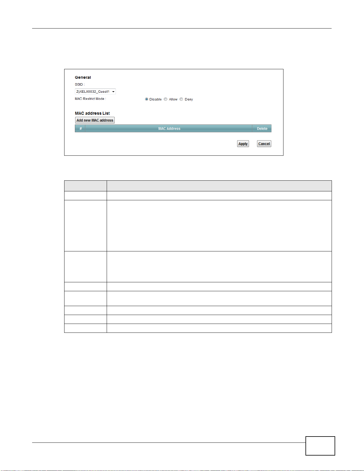
Chapter 6 Wireless
Use this screen to view your Device’s MAC filter settings and add new MAC filter rules. Click
Network Setting > Wireless > MAC Authentication. The screen appears as shown.
Figure 36 Wireless > MAC Authentication
The following table describes the labels in this screen.
Table 23 Wireless > MAC Authentication
LABEL DESCRIPTION
SSID Select the SSID for which you want to configure MAC filter settings.
MAC Restrict
Mode
Add new MAC
address
# This is the index number of the entry.
MAC Address This is the MAC addresses of the wireless devices that are allowed or denied access to the
Delete Click the Delete icon to delete the entry.
Apply Click Apply to save your changes.
Cancel Click Cancel to exit this screen without saving.
Define the filter action for the list of MAC addresses in the MAC Address table.
Select Disable to turn off MAC filtering.
Select Deny to block access to the Device. MAC addresses not listed will be allowed to
access the Device.
Select Allow to permit access to the Device. MAC addresses not listed will be denied access
to the Device.
Click this if you want to add a new MAC address entry to the MAC filter list below.
Enter the MAC addresses of the wireless devices that are allowed or denied access to the
Device in these address fields. Enter the MAC addresses in a valid MAC address format, that
is, six hexadecimal character pairs, for example, 12:34:56:78:9a:bc.
Device.
6.5 The WPS Screen
Use this screen to configure WiFi Protected Setup (WPS) on your Device.
WPS allows you to quickly set up a wireless network with strong security, without having to
configure security settings manually. Set up each WPS connection between two devices. Both
devices must support WPS. See Section 6.10.9.3 on page 95 for more information about WPS.
VMG1312-B10C User’s Guide
79

Chapter 6 Wireless
Note: The Device applies the security settings of the SSID1 profile (see Section 6.2 on
Click Network Setting > Wireless > WPS. The following screen displays. Select Enable and click
Apply to activate the WPS function. Then you can configure the WPS settings in this screen.
Figure 37 Network Setting > Wireless > WPS
page 66). If you want to use the WPS feature, make sure you have set the security
mode of SSID1 to WPA2-PSK or No Security.
The following table describes the labels in this screen.
Table 24 Network Setting > Wireless > WPS
LABEL DESCRIPTION
WPS Select Enable to activate WPS on the Device.
WPS 2.0 Select Enable to have the device use WPS 2.0 or Disable to have it use WPS 1.0.
Method 1 Use this section to set up a WPS wireless network using Push Button Configuration (PBC).
Connect Click this button to add another WPS-enabled wireless device (within wireless range of the
Device) to your wireless network. This button may either be a physical button on the
outside of device, or a menu button similar to the Connect button on this screen.
Note: You must press the other wireless device’s WPS button within two minutes of pressing
this button.
Method 2 Use this section to set up a WPS wireless network by entering the PIN of the client into the
Device.
Register Enter the PIN of the device that you are setting up a WPS connection with and click
Register to authenticate and add the wireless device to your wireless network.
You can find the PIN either on the outside of the device, or by checking the device’s
settings.
Note: You must also activate WPS on that device within two minutes to have it present its
PIN to the Device.
80
VMG1312-B10C User’s Guide

Table 24 Network Setting > Wireless > WPS (continued)
LABEL DESCRIPTION
Method 3 Use this section to set up a WPS wireless network by entering the PIN of the Device into
the client.
Release
Configuration
Generate
New PIN
Number
Apply Click Apply to save your changes.
Cancel Click Cancel to restore your previously saved settings.
The default WPS status is configured.
Click this button to remove all configured wireless and wireless security settings for WPS
connections on the Device.
The PIN (Personal Identification Number) of the Device is shown here. Enter this PIN in the
configuration utility of the device you want to connect to using WPS.
The PIN is not necessary when you use WPS push-button method.
Click the Generate New PIN Number button to have the Device create a new PIN.
6.6 The WMM Screen
Use this screen to enable Wi-Fi MultiMedia (WMM) and WMM Power Save in wireless networks for
multimedia applications.
Chapter 6 Wireless
Click Network Setting > Wireless > WMM. The following screen displays.
Figure 38 Network Setting > Wireless > WMM
The following table describes the labels in this screen.
Table 25 Network Setting > Wireless > WMM
LABEL DESCRIPTION
WMM Select On to have the Device automatically give a service a priority level according to the
ToS value in the IP header of packets it sends. WMM QoS (Wifi MultiMedia Quality of
Service) gives high priority to voice and video, which makes them run more smoothly.
WMM
Automatic
Power Save
Delivery
Select this option to extend the battery life of your mobile devices (especially useful for
small devices that are running multimedia applications). The Device goes to sleep mode to
save power when it is not transmitting data. The AP buffers the packets sent to the Device
until the Device "wakes up". The Device wakes up periodically to check for incoming data.
Note: Note: This works only if the wireless device to which the Device is connected also
supports this feature.
Apply Click Apply to save your changes.
Cancel Click Cancel to restore your previously saved settings.
VMG1312-B10C User’s Guide
81

Chapter 6 Wireless
6.7 The WDS Screen
An AP using the Wireless Distribution System (WDS) can function as a wireless network bridge
allowing you to wirelessly connect two wired network segments. The WDS screen allows you to
configure the Device to connect to two or more APs wirelessly when WDS is enabled.
Use this screen to set up your WDS (Wireless Distribution System) links between the Device and
other wireless APs. You need to know the MAC address of the peer device. Once the security
settings of peer sides match one another, the connection between devices is made.
Note: WDS security is independent of the security settings between the Device and any
wireless clients.
Note: At the time of writing, WDS is compatible with other ZyXEL APs only. Not all models
support WDS links. Check your other AP’s documentation.
Click Network Setting > Wireless > WDS. The following screen displays.
Figure 39 Network Setting > Wireless > WDS
82
The following table describes the labels in this screen.
Table 26 Network Setting > Wireless > WDS
LABEL DESCRIPTION
Wireless Bridge Setup
AP Mode Select the operating mode for your Device.
• Access Point - The Device functions as a bridge and access point simultaneously.
• Wireless Bridge - The Device acts as a wireless network bridge and establishes
wireless links with other APs. In this mode, clients cannot connect to the Device
wirelessly.
Bridge Restrict This field is available only when you set operating mode to Access Point.
Select Enabled to turn on WDS and enter the peer device’s MAC address manually in the
table below. Select Disable to turn off WDS.
VMG1312-B10C User’s Guide

Table 26 Network Setting > Wireless > WDS (continued)
LABEL DESCRIPTION
Remote Bridge
MAC Address
# This is the index number of the entry.
MAC Address This shows the MAC address of the peer device.
Modify/Delete Click the Edit icon and type the MAC address of the peer device in a valid MAC address
Scan Click the Scan icon to search and display the available APs within range.
Apply Click Apply to save your changes.
Cancel Click Cancel to restore your previously saved settings.
6.7.1 WDS Scan
You can click the Scan icon in Wireless > WDS to have the Device automatically search and
display the available APs within range. Select an AP and click Apply to have the Device establish a
wireless link with the selected wireless device.
Chapter 6 Wireless
You can enter the MAC address of the peer device by clicking the Edit icon under Modify.
You can connect to up to 4 peer devices.
format (six hexadecimal character pairs, for example 12:34:56:78:9a:bc).
Click the Delete icon to remove this entry.
Figure 40 WDS: Scan
The following table describes the labels in this screen.
Table 27 WDS: Scan
LABEL DESCRIPTION
Wireless Bridge Scan Setup
Refresh Click Refresh to update the table.
# This is the index number of the entry.
SSID This shows the SSID of the available wireless device within range.
BSSID This shows the MAC address of the available wireless device within range.
Apply Click Apply to save your changes.
Cancel Click Cancel to restore your previously saved settings.
VMG1312-B10C User’s Guide
83

Chapter 6 Wireless
6.8 The Others Screen
Use this screen to configure advanced wireless settings. Click Network Setting > Wireless >
Others. The screen appears as shown.
See Section 6.10.2 on page 88 for detailed definitions of the terms listed in this screen.
Figure 41 Network Setting > Wireless > Others
The following table describes the labels in this screen.
Table 28 Network Setting > Wireless > Others
LABEL DESCRIPTION
RTS/CTS
Threshold
Fragmentation
Threshold
Auto Channel
Timer
Output Power Set the output power of the Device. If there is a high density of APs in an area, decrease
Beacon Interval When a wirelessly networked device sends a beacon, it includes with it a beacon interval.
DTIM Interval Delivery Traffic Indication Message (DTIM) is the time period after which broadcast and
Data with its frame size larger than this value will perform the RTS (Request To Send)/CTS
(Clear To Send) handshake.
Enter a value between 0 and 2347.
This is the maximum data fragment size that can be sent. Enter a value between 256 and
2346.
If you set the channel to Auto in the Network Setting > Wireless > G eneral screen,
specify the interval in minutes for how often the Device scans for the best channel. Enter 0
to disable the periodical scan.
the output power to reduce interference with other APs. Select one of the following: 20%,
40%, 60%, 80% or 100%.
This specifies the time period before the device sends the beacon again.
The interval tells receiving devices on the network how long they can wait in low power
mode before waking up to handle the beacon. This value can be set from 50ms to 1000ms.
A high value helps save current consumption of the access point.
multicast packets are transmitted to mobile clients in the Power Saving mode. A high DTIM
value can cause clients to lose connectivity with the network. This value can be set from 1
to 255.
84
VMG1312-B10C User’s Guide

Chapter 6 Wireless
Table 28 Network Setting > Wireless > Others (continued)
LABEL DESCRIPTION
802.11 Mode Select 802.11b Only to allow only IEEE 802.11b compliant WLAN devices to associate with
the Device.
Select 802.11g Only to allow only IEEE 802.11g compliant WLAN devices to associate with
the Device.
Select 802.11n Only to allow only IEEE 802.11n compliant WLAN devices to associate with
the Device.
Select 802.11b/g Mixed to allow either IEEE 802.11b or IEEE 802.11g compliant WLAN
devices to associate with the Device. The transmission rate of your Device might be
reduced.
Select 802.11b/g/n Mixed to allow IEEE 802.11b, IEEE 802.11g or IEEE802.11n
compliant WLAN devices to associate with the Device. The transmission rate of your Device
might be reduced.
802.11
Protection
Enabling this feature can help prevent collisions in mixed-mode networks (networks with
both IEEE 802.11b and IEEE 802.11g traffic).
Select Auto to have the wireless devices transmit data after a RTS/CTS handshake. This
helps improve IEEE 802.11g performance.
Select Off to disable 802.11 protection. The transmission rate of your Device might be
reduced in a mixed-mode network.
This field displays Off and is not configurable when you set 802.11 Mode to 802.11b
Only.
Preamble Select a preamble type from the drop-down list box. Choices are Long or Short. See
Section 6.10.7 on page 92 for more information.
This field is configurable only when you set 802.11 Mode to 802.11b.
Apply Click Apply to save your changes.
Cancel Click Cancel to restore your previously saved settings.
VMG1312-B10C User’s Guide
85

Chapter 6 Wireless
6.9 The Channel Status Screen
Use the Channel Status screen to scan wireless LAN channel noises and view the results. Click
Network Setting > Wireless > Channel Status. The screen appears as shown. Click Scan to
scan the wireless LAN channels. You can view the results in the Channel Scan Result section.
Figure 42 Network Setting > Wireless > Channel Status
6.10 Technical Reference
This section discusses wireless LANs in depth.
6.10.1 Wireless Network Overview
Wireless networks consist of wireless clients, access points and bridges.
• A wireless client is a radio connected to a user’s computer.
• An access point is a radio with a wired connection to a network, which can connect with
numerous wireless clients and let them access the network.
• A bridge is a radio that relays communications between access points and wireless clients,
extending a network’s range.
86
VMG1312-B10C User’s Guide

Chapter 6 Wireless
Traditionally, a wireless network operates in one of two ways.
• An “infrastructure” type of network has one or more access points and one or more wireless
clients. The wireless clients connect to the access points.
• An “ad-hoc” type of network is one in which there is no access point. Wireless clients connect to
one another in order to exchange information.
The following figure provides an example of a wireless network.
Figure 43 Example of a Wireless Network
The wireless network is the part in the blue circle. In this wireless network, devices A and B use the
access point (AP) to interact with the other devices (such as the printer) or with the Internet. Your
Device is the AP.
Every wireless network must follow these basic guidelines.
• Every device in the same wireless network must use the same SSID.
The SSID is the name of the wireless network. It stands for Service Set IDentifier.
• If two wireless networks overlap, they should use a different channel.
Like radio stations or television channels, each wireless network uses a specific channel, or
frequency, to send and receive information.
• Every device in the same wireless network must use security compatible with the AP.
Security stops unauthorized devices from using the wireless network. It can also protect the
information that is sent in the wireless network.
VMG1312-B10C User’s Guide
87

Chapter 6 Wireless
Radio Channels
In the radio spectrum, there are certain frequency bands allocated for unlicensed, civilian use. For
the purposes of wireless networking, these bands are divided into numerous channels. This allows a
variety of networks to exist in the same place without interfering with one another. When you
create a network, you must select a channel to use.
Since the available unlicensed spectrum varies from one country to another, the number of
available channels also varies.
6.10.2 Additional Wireless Terms
The following table describes some wireless network terms and acronyms used in the Device’s Web
Configurator.
Table 29 Additional Wireless Terms
TERM DESCRIPTION
RTS/CTS Threshold In a wireless network which covers a large area, wireless devices are sometimes not
Preamble A preamble affects the timing in your wireless network. There are two preamble
Authentication The process of verifying whether a wireless device is allowed to use the wireless
Fragmentation
Threshold
aware of each other’s presence. This may cause them to send information to the AP
at the same time and result in information colliding and not getting through.
By setting this value lower than the default value, the wireless devices must
sometimes get permission to send information to the Device. The lower the value, the
more often the devices must get permission.
If this value is greater than the fragmentation threshold value (see below), then
wireless devices never have to get permission to send information to the Device.
modes: long and short. If a device uses a different preamble mode than the Device
does, it cannot communicate with the Device.
network.
A small fragmentation threshold is recommended for busy networks, while a larger
threshold provides faster performance if the network is not very busy.
6.10.3 Wireless Security Overview
By their nature, radio communications are simple to intercept. For wireless data networks, this
means that anyone within range of a wireless network without security can not only read the data
passing over the airwaves, but also join the network. Once an unauthorized person has access to
the network, he or she can steal information or introduce malware (malicious software) intended to
compromise the network. For these reasons, a variety of security systems have been developed to
ensure that only authorized people can use a wireless data network, or understand the data carried
on it.
These security standards do two things. First, they authenticate. This means that only people
presenting the right credentials (often a username and password, or a “key” phrase) can access the
network. Second, they encrypt. This means that the information sent over the air is encoded. Only
people with the code key can understand the information, and only people who have been
authenticated are given the code key.
These security standards vary in effectiveness. Some can be broken, such as the old Wired
Equivalent Protocol (WEP). Using WEP is better than using no security at all, but it will not keep a
determined attacker out. Other security standards are secure in themselves but can be broken if a
88
VMG1312-B10C User’s Guide

user does not use them properly. For example, the WPA-PSK security standard is very secure if you
use a long key which is difficult for an attacker’s software to guess - for example, a twenty-letter
long string of apparently random numbers and letters - but it is not very secure if you use a short
key which is very easy to guess - for example, a three-letter word from the dictionary.
Because of the damage that can be done by a malicious attacker, it’s not just people who have
sensitive information on their network who should use security. Everybody who uses any wireless
network should ensure that effective security is in place.
A good way to come up with effective security keys, passwords and so on is to use obscure
information that you personally will easily remember, and to enter it in a way that appears random
and does not include real words. For example, if your mother owns a 1970 Dodge Challenger and
her favorite movie is Vanishing Point (which you know was made in 1971) you could use
“70dodchal71vanpoi” as your security key.
The following sections introduce different types of wireless security you can set up in the wireless
network.
6.10.3.1 SSID
Normally, the Device acts like a beacon and regularly broadcasts the SSID in the area. You can hide
the SSID instead, in which case the Device does not broadcast the SSID. In addition, you should
change the default SSID to something that is difficult to guess.
Chapter 6 Wireless
This type of security is fairly weak, however, because there are ways for unauthorized wireless
devices to get the SSID. In addition, unauthorized wireless devices can still see the information that
is sent in the wireless network.
6.10.3.2 MAC Address Filter
Every device that can use a wireless network has a unique identification number, called a MAC
address.
00A0C5000002 or 00:A0:C5:00:00:02. To get the MAC address for each device in the wireless
network, see the device’s User’s Guide or other documentation.
You can use the MAC address filter to tell the Device which devices are allowed or not allowed to
use the wireless network. If a device is allowed to use the wireless network, it still has to have the
correct information (SSID, channel, and security). If a device is not allowed to use the wireless
network, it does not matter if it has the correct information.
This type of security does not protect the information that is sent in the wireless network.
Furthermore, there are ways for unauthorized wireless devices to get the MAC address of an
authorized device. Then, they can use that MAC address to use the wireless network.
1
A MAC address is usually written using twelve hexadecimal characters2; for example,
6.10.3.3 User Authentication
Authentication is the process of verifying whether a wireless device is allowed to use the wireless
network. You can make every user log in to the wireless network before using it. However, every
device in the wireless network has to support IEEE 802.1x to do this.
1. Some wireless devices, such as scanners, can detect wireless networks but cannot use wireless networks. These kinds
of wireless devices might not have MAC addresses.
2. Hexadecimal characters are 0, 1, 2, 3, 4, 5, 6, 7, 8, 9, A, B, C, D, E, and F.
VMG1312-B10C User’s Guide
89

Chapter 6 Wireless
For wireless networks, you can store the user names and passwords for each user in a RADIUS
server. This is a server used in businesses more than in homes. If you do not have a RADIUS server,
you cannot set up user names and passwords for your users.
Unauthorized wireless devices can still see the information that is sent in the wireless network,
even if they cannot use the wireless network. Furthermore, there are ways for unauthorized
wireless users to get a valid user name and password. Then, they can use that user name and
password to use the wireless network.
6.10.3.4 Encryption
Wireless networks can use encryption to protect the information that is sent in the wireless
network. Encryption is like a secret code. If you do not know the secret code, you cannot
understand the message.
The types of encryption you can choose depend on the type of authentication. (See Section
6.10.3.3 on page 89 for information about this.)
Table 30 Types of Encryption for Each Type of Authentication
Weakest No Security WPA
NO AUTHENTICATION RADIUS SERVER
Static WEP
WPA-PSK
Strongest WPA2-PSK WPA2
For example, if the wireless network has a RADIUS server, you can choose WPA or WPA2. If users
do not log in to the wireless network, you can choose no encryption, Static WEP, WPA-PSK, or
WPA2-PSK.
Usually, you should set up the strongest encryption that every device in the wireless network
supports. For example, suppose you have a wireless network with the Device and you do not have
a RADIUS server. Therefore, there is no authentication. Suppose the wireless network has two
devices. Device A only supports WEP, and device B supports WEP and WPA. Therefore, you should
set up Static WEP in the wireless network.
Note: It is recommended that wireless networks use WPA-PSK, WPA, or stronger
encryption. The other types of encryption are better than none at all, but it is still
possible for unauthorized wireless devices to figure out the original information
pretty quickly.
When you select WPA2 or WPA2-PSK in your Device, you can also select an option (WPA
compatible) to support WPA as well. In this case, if some of the devices support WPA and some
support WPA2, you should set up WPA2-PSK or WPA2 (depending on the type of wireless network
login) and select the WPA compatible option in the Device.
Many types of encryption use a key to protect the information in the wireless network. The longer
the key, the stronger the encryption. Every device in the wireless network must have the same key.
90
VMG1312-B10C User’s Guide

6.10.4 Signal Problems
Because wireless networks are radio networks, their signals are subject to limitations of distance,
interference and absorption.
Problems with distance occur when the two radios are too far apart. Problems with interference
occur when other radio waves interrupt the data signal. Interference may come from other radio
transmissions, such as military or air traffic control communications, or from machines that are
coincidental emitters such as electric motors or microwaves. Problems with absorption occur when
physical objects (such as thick walls) are between the two radios, muffling the signal.
6.10.5 BSS
A Basic Service Set (BSS) exists when all communications between wireless stations or between a
wireless station and a wired network client go through one access point (AP).
Intra-BSS traffic is traffic between wireless stations in the BSS. When Intra-BSS traffic blocking is
disabled, wireless station A and B can access the wired network and communicate with each other.
When Intra-BSS traffic blocking is enabled, wireless station A and B can still access the wired
network but cannot communicate with each other.
Chapter 6 Wireless
Figure 44 Basic Service set
6.10.6 MBSSID
Traditionally, you need to use different APs to configure different Basic Service Sets (BSSs). As well
as the cost of buying extra APs, there is also the possibility of channel interference. The Device’s
VMG1312-B10C User’s Guide
91

Chapter 6 Wireless
MBSSID (Multiple Basic Service Set IDentifier) function allows you to use one access point to
provide several BSSs simultaneously. You can then assign varying QoS priorities and/or security
modes to different SSIDs.
Wireless devices can use different BSSIDs to associate with the same AP.
6.10.6.1 Notes on Multiple BSSs
• A maximum of eight BSSs are allowed on one AP simultaneously.
• You must use different keys for different BSSs. If two wireless devices have different BSSIDs
(they are in different BSSs), but have the same keys, they may hear each other’s
communications (but not communicate with each other).
• MBSSID should not replace but rather be used in conjunction with 802.1x security.
6.10.7 Preamble Type
Preamble is used to signal that data is coming to the receiver. Short and long refer to the length of
the synchronization field in a packet.
Short preamble increases performance as less time sending preamble means more time for sending
data. All IEEE 802.11 compliant wireless adapters support long preamble, but not all support short
preamble.
Use long preamble if you are unsure what preamble mode other wireless devices on the network
support, and to provide more reliable communications in busy wireless networks.
Use short preamble if you are sure all wireless devices on the network support it, and to provide
more efficient communications.
Use the dynamic setting to automatically use short preamble when all wireless devices on the
network support it, otherwise the Device uses long preamble.
Note: The wireless devices MUST use the same preamble mode in order to communicate.
6.10.8 Wireless Distribution System (WDS)
The Device can act as a wireless network bridge and establish WDS (Wireless Distribution System)
links with other APs. You need to know the MAC addresses of the APs you want to link to. Once the
security settings of peer sides match one another, the connection between devices is made.
At the time of writing, WDS security is compatible with other ZyXEL access points only. Refer to
your other access point’s documentation for details.
The following figure illustrates how WDS link works between APs. Notebook computer A is a
wireless client connecting to access point AP 1. AP 1 has no wired Internet connection, but it can
92
VMG1312-B10C User’s Guide

establish a WDS link with access point AP 2, which has a wired Internet connection. When AP 1
WDS
AP 2
AP 1
A
has a WDS link with AP 2, the notebook computer can access the Internet through AP 2.
Figure 45 WDS Link Example
6.10.9 WiFi Protected Setup (WPS)
Your Device supports WiFi Protected Setup (WPS), which is an easy way to set up a secure wireless
network. WPS is an industry standard specification, defined by the WiFi Alliance.
WPS allows you to quickly set up a wireless network with strong security, without having to
configure security settings manually. Each WPS connection works between two devices. Both
devices must support WPS (check each device’s documentation to make sure).
Chapter 6 Wireless
Depending on the devices you have, you can either press a button (on the device itself, or in its
configuration utility) or enter a PIN (a unique Personal Identification Number that allows one device
to authenticate the other) in each of the two devices. When WPS is activated on a device, it has two
minutes to find another device that also has WPS activated. Then, the two devices connect and set
up a secure network by themselves.
6.10.9.1 Push Button Configuration
WPS Push Button Configuration (PBC) is initiated by pressing a button on each WPS-enabled
device, and allowing them to connect automatically. You do not need to enter any information.
Not every WPS-enabled device has a physical WPS button. Some may have a WPS PBC button in
their configuration utilities instead of or in addition to the physical button.
Take the following steps to set up WPS using the button.
1 Ensure that the two devices you want to set up are within wireless range of one another.
2 Look for a WPS button on each device. If the device does not have one, log into its configuration
utility and locate the button (see the device’s User’s Guide for how to do this - for the Device, see
Section 6.6 on page 81).
3 Press the button on one of the devices (it doesn’t matter which). For the Device you must press the
WPS button for more than three seconds.
4 Within two minutes, press the button on the other device. The registrar sends the network name
VMG1312-B10C User’s Guide
(SSID) and security key through an secure connection to the enrollee.
If you need to make sure that WPS worked, check the list of associated wireless clients in the AP’s
configuration utility. If you see the wireless client in the list, WPS was successful.
93

Chapter 6 Wireless
6.10.9.2 PIN Configuration
Each WPS-enabled device has its own PIN (Personal Identification Number). This may either be
static (it cannot be changed) or dynamic (in some devices you can generate a new PIN by clicking
on a button in the configuration interface).
Use the PIN method instead of the push-button configuration (PBC) method if you want to ensure
that the connection is established between the devices you specify, not just the first two devices to
activate WPS in range of each other. However, you need to log into the configuration interfaces of
both devices to use the PIN method.
When you use the PIN method, you must enter the PIN from one device (usually the wireless client)
into the second device (usually the Access Point or wireless router). Then, when WPS is activated
on the first device, it presents its PIN to the second device. If the PIN matches, one device sends
the network and security information to the other, allowing it to join the network.
Take the following steps to set up a WPS connection between an access point or wireless router
(referred to here as the AP) and a client device using the PIN method.
1 Ensure WPS is enabled on both devices.
2 Access the WPS section of the AP’s configuration interface. See the device’s User’s Guide for how to
do this.
3 Look for the client’s WPS PIN; it will be displayed either on the device, or in the WPS section of the
client’s configuration interface (see the device’s User’s Guide for how to find the WPS PIN - for the
Device, see Section 6.5 on page 79).
4 Enter the client’s PIN in the AP’s configuration interface.
5 If the client device’s configuration interface has an area for entering another device’s PIN, you can
either enter the client’s PIN in the AP, or enter the AP’s PIN in the client - it does not matter which.
6 Start WPS on both devices within two minutes.
7 Use the configuration utility to activate WPS, not the push-button on the device itself.
8 On a computer connected to the wireless client, try to connect to the Internet. If you can connect,
WPS was successful.
If you cannot connect, check the list of associated wireless clients in the AP’s configuration utility. If
you see the wireless client in the list, WPS was successful.
94
VMG1312-B10C User’s Guide

Chapter 6 Wireless
ENROLLEE
SECURE EAP TUNNEL
SSID
WPA(2)-PSK
WITHIN 2 MINUTES
COMMUNICATION
This device’s
WPS
Enter WPS PIN
WPS
from other device:
WPS PIN: 123456
WPS
START
WPS
START
REGISTRAR
The following figure shows a WPS-enabled wireless client (installed in a notebook computer)
connecting to the WPS-enabled AP via the PIN method.
Figure 46 Example WPS Process: PIN Method
6.10.9.3 How WPS Works
When two WPS-enabled devices connect, each device must assume a specific role. One device acts
as the registrar (the device that supplies network and security settings) and the other device acts
as the enrollee (the device that receives network and security settings. The registrar creates a
secure EAP (Extensible Authentication Protocol) tunnel and sends the network name (SSID) and the
WPA-PSK or WPA2-PSK pre-shared key to the enrollee. Whether WPA-PSK or WPA2-PSK is used
depends on the standards supported by the devices. If the registrar is already part of a network, it
sends the existing information. If not, it generates the SSID and WPA(2)-PSK randomly.
VMG1312-B10C User’s Guide
95

Chapter 6 Wireless
SECURE TUNNEL
SECURITY INFO
WITHIN 2 MINUTES
COMMUNICATION
ACTIVATE
WPS
ACTIVATE
WPS
WPS HANDSHAKE
REGISTRARENROLLEE
The following figure shows a WPS-enabled client (installed in a notebook computer) connecting to a
WPS-enabled access point.
Figure 47 How WPS works
6.10.9.4 Example WPS Network Setup
The roles of registrar and enrollee last only as long as the WPS setup process is active (two
minutes). The next time you use WPS, a different device can be the registrar if necessary.
The WPS connection process is like a handshake; only two devices participate in each WPS
transaction. If you want to add more devices you should repeat the process with one of the existing
networked devices and the new device.
Note that the access point (AP) is not always the registrar, and the wireless client is not always the
enrollee. All WPS-certified APs can be a registrar, and so can some WPS-enabled wireless clients.
By default, a WPS devices is “unconfigured”. This means that it is not part of an existing network
and can act as either enrollee or registrar (if it supports both functions). If the registrar is
unconfigured, the security settings it transmits to the enrollee are randomly-generated. Once a
WPS-enabled device has connected to another device using WPS, it becomes “configured”. A
configured wireless client can still act as enrollee or registrar in subsequent WPS connections, but a
configured access point can no longer act as enrollee. It will be the registrar in all subsequent WPS
connections in which it is involved. If you want a configured AP to act as an enrollee, you must reset
it to its factory defaults.
This section shows how security settings are distributed in an example WPS setup.
The following figure shows an example network. In step 1, both AP1 and Client 1 are
unconfigured. When WPS is activated on both, they perform the handshake. In this example, AP1
96
VMG1312-B10C User’s Guide

Chapter 6 Wireless
REGISTRARENROLLEE
SECURITY INFO
CLIENT 1
AP1
REGISTRAR
CLIENT 1
AP1
ENROLLEE
CLIENT 2
EXISTING CONNECTION
S
E
C
U
R
I
T
Y
I
N
F
O
is the registrar, and Client 1 is the enrollee. The registrar randomly generates the security
information to set up the network, since it is unconfigured and has no existing information.
Figure 48 WPS: Example Network Step 1
In step 2, you add another wireless client to the network. You know that Client 1 supports registrar
mode, but it is better to use AP1 for the WPS handshake with the new client since you must
connect to the access point anyway in order to use the network. In this case, AP1 must be the
registrar, since it is configured (it already has security information for the network). AP1 supplies
the existing security information to Client 2.
Figure 49 WPS: Example Network Step 2
VMG1312-B10C User’s Guide
97

Chapter 6 Wireless
CLIENT 1
AP1
REGISTRAR
CLIENT 2
EXISTING CONNECTION
S
E
C
U
R
I
T
Y
I
N
F
O
ENROLLEE
AP2
E
X
I
S
T
I
N
G
C
O
N
N
E
C
T
I
O
N
In step 3, you add another access point (AP2) to your network. AP2 is out of range of AP1, so you
cannot use AP1 for the WPS handshake with the new access point. However, you know that Client
2 supports the registrar function, so you use it to perform the WPS handshake instead.
Figure 50 WPS: Example Network Step 3
6.10.9.5 Limitations of WPS
WPS has some limitations of which you should be aware.
• WPS works in Infrastructure networks only (where an AP and a wireless client communicate). It
does not work in Ad-Hoc networks (where there is no AP).
• When you use WPS, it works between two devices only. You cannot enroll multiple devices
simultaneously, you must enroll one after the other.
For instance, if you have two enrollees and one registrar you must set up the first enrollee (by
pressing the WPS button on the registrar and the first enrollee, for example), then check that it
successfully enrolled, then set up the second device in the same way.
• WPS works only with other WPS-enabled devices. However, you can still add non-WPS devices to
a network you already set up using WPS.
WPS works by automatically issuing a randomly-generated WPA-PSK or WPA2-PSK pre-shared
key from the registrar device to the enrollee devices. Whether the network uses WPA-PSK or
WPA2-PSK depends on the device. You can check the configuration interface of the registrar
device to discover the key the network is using (if the device supports this feature). Then, you
can enter the key into the non-WPS device and join the network as normal (the non-WPS device
must also support WPA-PSK or WPA2-PSK).
98
VMG1312-B10C User’s Guide

Chapter 6 Wireless
• When you use the PBC method, there is a short period (from the moment you press the button
on one device to the moment you press the button on the other device) when any WPS-enabled
device could join the network. This is because the registrar has no way of identifying the
“correct” enrollee, and cannot differentiate between your enrollee and a rogue device. This is a
possible way for a hacker to gain access to a network.
You can easily check to see if this has happened. WPS works between only two devices
simultaneously, so if another device has enrolled your device will be unable to enroll, and will not
have access to the network. If this happens, open the access point’s configuration interface and
look at the list of associated clients (usually displayed by MAC address). It does not matter if the
access point is the WPS registrar, the enrollee, or was not involved in the WPS handshake; a
rogue device must still associate with the access point to gain access to the network. Check the
MAC addresses of your wireless clients (usually printed on a label on the bottom of the device). If
there is an unknown MAC address you can remove it or reset the AP.
VMG1312-B10C User’s Guide
99

Chapter 6 Wireless
100
VMG1312-B10C User’s Guide
 Loading...