

Page 1

ZyWALL 10~100 Series
Internet Security Gateway
Reference Guide
Versions 3.52, 3.60 and 3.61
March 2003
Page 2

ZyWALL 10~100 Series Internet Security Gateway
Copyright
Copyright © 2003 by ZyXEL Communications Corporation.
The contents of this publication may not be reproduced in any part or as a whole, transcribed, stored in a
retrieval system, translated into any language, or transmitted in any form or by any means, electronic,
mechanical, magnetic, optical, chemical, photocopying, manual, or otherwise, without the prior written
permission of ZyXEL Communications Corporation.
Published by ZyXEL Communications Corporation. All rights reserved.
Disclaimer
ZyXEL does not assume any liability arising out of the application or use of any products, or software
described herein. Neither does it convey any license under its patent rights nor the patent rights of others.
ZyXEL further reserves the right to make changes in any products described herein without notice.
This publication is subject to change without notice.
Trademarks
Trademarks mentioned in this publication are used for identification purposes only and may be properties of
their respective owners.
ii Copyright
Page 3

ZyWALL 10~100 Series Internet Security Gateway
Federal Communications Commission (FCC)
Interference Statement
This device complies with Part 15 of FCC rules. Operation is subject to the following two conditions:
This device may not cause harmful interference.
This device must accept any interference received, including interference that may cause undesired
operations.
This equipment has been tested and found to comply with the limits for a CLASS B digital device pursuant to
Part 15 of the FCC Rules. These limits are designed to provide reasonable protection against harmful
interference in a commercial environment. This equipment generates, uses, and can radiate radio frequency
energy, and if not installed and used in accordance with the instructions, may cause harmful interference to
radio communications.
If this equipment does cause harmful interference to radio/television reception, which can be determined by
turning the equipment off and on, the user is encouraged to try to correct the interference by one or more of
the following measures:
Reorient or relocate the receiving antenna.
Increase the separation between the equipment and the receiver.
Connect the equipment into an outlet on a circuit different from that to which the receiver is connected.
Consult the dealer or an experienced radio/TV technician for help.
Notice 1
Changes or modifications not expressly approved by the party responsible for compliance could void the
user's authority to operate the equipment.
Certifications
Refer to the product page at www.zyxel.com.
FCC iii
Page 4

ZyWALL 10~100 Series Internet Security Gateway
Information for Canadian Users
The Industry Canada label identifies certified equipment. This certification means that the equipment meets
certain telecommunications network protective, operation, and safety requirements. The Industry Canada
does not guarantee that the equipment will operate to a user's satisfaction.
Before installing this equipment, users should ensure that it is permissible to be connected to the facilities of
the local telecommunications company. The equipment must also be installed using an acceptable method of
connection. In some cases, the company's inside wiring associated with a single line individual service may
be extended by means of a certified connector assembly. The customer should be aware that the compliance
with the above conditions may not prevent degradation of service in some situations.
Repairs to certified equipment should be made by an authorized Canadian maintenance facility designated by
the supplier. Any repairs or alterations made by the user to this equipment, or equipment malfunctions, may
give the telecommunications company cause to request the user to disconnect the equipment.
For their own protection, users should ensure that the electrical ground connections of the power utility,
telephone lines, and internal metallic water pipe system, if present, are connected together. This precaution
may be particularly important in rural areas.
Caution
Users should not attempt to make such connections themselves, but should contact the appropriate electrical
inspection authority, or electrician, as appropriate.
Note
This digital apparatus does not exceed the class A limits for radio noise emissions from digital apparatus set
out in the radio interference regulations of Industry Canada.
iv Information for Canadian Users
Page 5

ZyWALL 10~100 Series Internet Security Gateway
ZyXEL Limited Warranty
ZyXEL warrants to the original end user (purchaser) that this product is free from any defects in materials or
workmanship for a period of up to two years from the date of purchase. During the warranty period, and upon
proof of purchase, should the product have indications of failure due to faulty workmanship and/or materials,
ZyXEL will, at its discretion, repair or replace the defective products or components without charge for
either parts or labor, and to whatever extent it shall deem necessary to restore the product or components to
proper operating condition. Any replacement will consist of a new or re-manufactured functionally
equivalent product of equal value, and will be solely at the discretion of ZyXEL. This warranty shall not
apply if the product is modified, misused, tampered with, damaged by an act of God, or subjected to
abnormal working conditions.
NOTE
Repair or replacement, as provided under this warranty, is the exclusive remedy of the purchaser. This
warranty is in lieu of all other warranties, express or implied, including any implied warranty of
merchantability or fitness for a particular use or purpose. ZyXEL shall in no event be held liable for indirect
or consequential damages of any kind of character to the purchaser.
To obtain the services of this warranty, contact ZyXEL's Service Center for your Return Material
Authorization number (RMA). Products must be returned Postage Prepaid. It is recommended that the unit be
insured when shipped. Any returned products without proof of purchase or those with an out-dated warranty
will be repaired or replaced (at the discretion of ZyXEL) and the customer will be billed for parts and labor.
All repaired or replaced products will be shipped by ZyXEL to the corresponding return address, Postage
Paid. This warranty gives you specific legal rights, and you may also have other rights that vary from country
to country.
Online Registration
Register online registration at www.zyxel.com for free future product updates and information.
Warranty v
Page 6
ZyWALL 10~100 Series Internet Security Gateway
Customer Support
When you contact your customer support representative please have the following information ready:
Please have the following information ready when you contact customer support.
• Product model and serial number.
• Information in Menu 24.2.1 – System Information.
• Warranty Information.
• Date that you received your device.
• Brief description of the problem and the steps you took to solve it.
LOCATION
WORLDWIDE
AMERICA
METHOD
support@zyxel.com.tw
sales@zyxel.com.tw
support@zyxel.com +1-714-632-0882
sales@zyxel.com
support@zyxel.dk +45-3955-0700 www.zyxel.dk SCANDINAVIA
sales@zyxel.dk
support@zyxel.de +49-2405-6909-0 www.zyxel.de GERMANY
sales@zyxel.de
E-MAIL
SUPPORT/SALES
+886-3-578-2439 ftp.europe.zyxel.com
+1-714-632-0858 ftp.zyxel.com
+45-3955-0707 ftp.zyxel.dk
+49-2405-6909-99
TELEPHONE/FAX WEB SITE/ FTP SITE REGULAR MAIL
+886-3-578-3942 www.zyxel.com
www.europe.zyxel.com
www.zyxel.com NORTH
800-255-4101
ZyXEL Communications Corp.,
6 Innovation Road II, ScienceBased Industrial Park, Hsinchu
300, Taiwan
ZyXEL Communications Inc.,
1650 Miraloma Avenue,
Placentia, CA 92870, U.S.A.
ZyXEL Communications A/S,
Columbusvej 5, 2860 Soeborg,
Denmark
ZyXEL Deutschland GmbH.
Adenauerstr. 20/A2 D-52146
Wuerselen, Germany
vi Customer Support
Page 7

ZyWALL 10~100 Series Internet Security Gateway
Table of Contents
Copyright......................................................................................................................................................ii
Federal Communications Commission (FCC) Interference Statement................................................. iii
Information for Canadian Users ...............................................................................................................iv
ZyXEL Limited Warranty ..........................................................................................................................v
Customer Support ......................................................................................................................................vi
List of Diagrams..........................................................................................................................................ix
List of Charts ...............................................................................................................................................x
Preface ........................................................................................................................................................xii
General Information........................................................................................................................................ I
Chapter 1 Setting up Your Computer’s IP Address.............................................................................. 1-1
Chapter 2 Triangle Route........................................................................................................................ 2-1
Chapter 3 The Big Picture ...................................................................................................................... 3-1
Chapter 4 Wireless LAN and IEEE 802.11............................................................................................ 4-1
Chapter 5 Wireless LAN With IEEE 802.1x .........................................................................................5-1
Chapter 6 PPPoE..................................................................................................................................... 6-1
Chapter 7 PPTP....................................................................................................................................... 7-1
Chapter 8 IP Subnetting.......................................................................................................................... 8-1
Command and Log Information....................................................................................................................II
Chapter 9 Command Interpreter ........................................................................................................... 9-1
Chapter 10 Firewall Commands........................................................................................................... 10-1
Chapter 11 NetBIOS Filter Commands ................................................................................................11-1
Chapter 12 Boot Commands................................................................................................................. 12-1
Chapter 13 Log Descriptions ................................................................................................................ 13-1
Chapter 14 Brute-Force Password Guessing Protection .................................................................... 14-1
Index............................................................................................................................................................... III
Table of Contents vii
Page 8

ZyWALL 10~100 Series Internet Security Gateway
Index ............................................................................................................................................................ A
viii Table of Contents
Page 9

ZyWALL 10~100 Series Internet Security Gateway
List of Diagrams
Diagram 2-1 Ideal Setup ................................................................................................................................ 2-1
Diagram 2-2 “Triangle Route” Problem ........................................................................................................ 2-2
Diagram 2-3 IP Alias...................................................................................................................................... 2-2
Diagram 2-4 Gateways on the WAN Side...................................................................................................... 2-3
Diagram 3-1 Big Picture— Filtering, Firewall, VPN and NAT ..................................................................... 3-1
Diagram 4-1 Peer-to-Peer Communication in an Ad-hoc Network................................................................ 4-3
Diagram 4-2 ESS Provides Campus-Wide Coverage..................................................................................... 4-4
Diagram 5-1 Sequences for EAP MD5–Challenge Authentication................................................................ 5-2
Diagram 6-1 Single-PC per Modem Hardware Configuration....................................................................... 6-1
Diagram 6-2 ZyWALL as a PPPoE Client ..................................................................................................... 6-2
Diagram 7-1 Transport PPP frames over Ethernet ......................................................................................... 7-1
Diagram 7-2 PPTP Protocol Overview .......................................................................................................... 7-2
Diagram 7-3 Example Message Exchange between PC and an ANT ............................................................ 7-3
Diagram 11-1 NetBIOS Display Filter Settings Command Without DMZ Example....................................11-2
Diagram 11-2 NetBIOS Display Filter Settings Command With DMZ Example.........................................11-2
Diagram 12-1 Option to Enter Debug Mode................................................................................................ 12-1
Diagram 12-2 Boot Module Commands...................................................................................................... 12-2
Diagram 13-1 Example VPN Initiator IPSec Log ...................................................................................... 13-12
Diagram 13-2 Example VPN Responder IPSec Log.................................................................................. 13-12
List of Diagrams ix
Page 10

ZyWALL 10~100 Series Internet Security Gateway
List of Charts
Chart 8-1 Classes of IP Addresses ..................................................................................................................8-1
Chart 8-2 Allowed IP Address Range By Class ..............................................................................................8-2
Chart 8-3 “Natural” Masks .............................................................................................................................8-2
Chart 8-4 Alternative Subnet Mask Notation..................................................................................................8-3
Chart 8-5 Subnet 1 ..........................................................................................................................................8-4
Chart 8-6 Subnet 2 ..........................................................................................................................................8-4
Chart 8-7 Subnet 1 ..........................................................................................................................................8-5
Chart 8-8 Subnet 2 ..........................................................................................................................................8-5
Chart 8-9 Subnet 3 ..........................................................................................................................................8-5
Chart 8-10 Subnet 4 ........................................................................................................................................8-6
Chart 8-11 Eight Subnets................................................................................................................................8-6
Chart 8-12 Class C Subnet Planning...............................................................................................................8-7
Chart 8-13 Class B Subnet Planning...............................................................................................................8-7
Chart 10-1 Firewall Commands....................................................................................................................10-1
Chart 11-1 NetBIOS Filter Default Settings ................................................................................................. 11-2
Chart 13-1 System Error Logs......................................................................................................................13-1
Chart 13-2 System Maintenance Logs..........................................................................................................13-1
Chart 13-3 UPnP Logs.................................................................................................................................. 13-2
Chart 13-4 Content Filtering Logs................................................................................................................13-2
Chart 13-5 Attack Logs.................................................................................................................................13-2
Chart 13-6 Access Logs ................................................................................................................................13-5
Chart 13-7 ACL Setting Notes ......................................................................................................................13-9
Chart 13-8 ICMP Notes ..............................................................................................................................13-10
Chart 13-9 Sys log ......................................................................................................................................13-11
Chart 13-10 Sample IKE Key Exchange Logs ...........................................................................................13-13
x List of Charts
Page 11

ZyWALL 10~100 Series Internet Security Gateway
Chart 13-11 Sample IPSec Logs During Packet Transmission .................................................................. 13-15
Chart 13-12 RFC-2408 ISAKMP Payload Types.......................................................................................13-16
Chart 13-13 Log Categories and Available Settings................................................................................... 13-17
Chart 14-1 Brute-Force Password Guessing Protection Commands............................................................ 14-1
List of Charts xi
Page 12

ZyWALL 10~100 Series Internet Security Gateway
Preface
About Your ZyWALL
Congratulations on your purchase of the ZyWALL Security Gateway.
About This User's Manual
This manual is designed to provide background information on some of the ZyWALL’s features. It also
includes commands for use with the command interpreter.
This manual may refer to the ZyWALL Internet Security Gateway as the ZyWALL.
This manual covers the ZyWALL 10 to 100 models. Supported features and the details of the features, vary
from model to model. Not every feature applies to every model; refer to the Model Comparison Chart in
chapter 1 of the Web Configurator User’s Guide to see what features are specific to your ZyWALL model.
You may use the System Management Terminal (SMT), web configurator or
command interpreter interface to configure your ZyWALL. Not all features can be
configured through all interfaces.
Related Documentation
Support Disk
Refer to the included CD for support documents.
Read Me First or Quick Start Guide
The Read Me First or Quick Start Guide is designed to help you get up and running right away. It
contains a detailed easy-to-follow connection diagram, default settings, handy checklists and
information on setting up your network and configuring for Internet access.
SMT User’s Guide
This manual is designed to guide you through the configuration of your ZyWALL using the System
Management Terminal.
Web Configurator User’s Guide
This manual is designed to guide you through the configuration of your ZyWALL using the
embedded web configurator.
Web Configurator Online Help
Embedded web help for descriptions of individual screens and supplementary information.
Packing List Card
The Packing List Card lists all items that should have come in the package.
Certifications
Refer to the product page at www.zyxel.com
ZyXEL Glossary and Web Site
Please refer to www.zyxel.com for an online glossary of networking terms and additional support
documentation.
for information on product certifications.
xii Preface
Page 13

ZyWALL 10~100 Series Internet Security Gateway
Syntax Conventions
• “Enter” means for you to type one or more characters and press the carriage return. “Select” or
“Choose” means for you to use one of the predefined choices.
• The SMT menu titles and labels are in Bold Times New Roman font.
• The choices of a menu item are in Bold Arial font.
• A single keystroke is in Arial font and enclosed in square brackets, for instance, [ENTER] means the
Enter, or carriage return, key; [ESC] means the escape key and [SPACE BAR] means the space bar.
[UP] and [DOWN] are the up and down arrow keys.
• Mouse action sequences are denoted using a comma. For example, “click the Apple icon, Control
Panels and then Modem” means first click the Apple icon, then point your mouse pointer to Control
Panels and then click Modem.
• For brevity’s sake, we will use “e.g.” as a shorthand for “for instance” and “i.e.” for “that is” or “in other
words” throughout this manual.
Preface xiii
Page 14

Page 15

General Information
Part I:
General Information
This part provides background information about setting up your computer’s IP address, triangle
route, how functions are related, wireless LAN, 802.1x, PPPoE, PPTP and IP subnetting.
I
Page 16

Page 17
ZyWALL 10~100 Series Internet Security Gateway
Chapter 1
Setting up Your Computer’s IP Address
All computers must have a 10M or 100M Ethernet adapter card and TCP/IP installed.
Windows 95/98/Me/NT/2000/XP, Macintosh OS 7 and later operating systems and all versions of
UNIX/LINUX include the software components you need to install and use TCP/IP on your computer.
Windows 3.1 requires the purchase of a third-party TCP/IP application package.
TCP/IP should already be installed on computers using Windows NT/2000/XP, Macintosh OS 7 and later
operating systems.
After the appropriate TCP/IP components are installed, configure the TCP/IP settings in order to
"communicate" with your network.
If you manually assign IP information instead of using dynamic assignment, make sure that your computers
have IP addresses that place them in the same subnet as the ZyWALL's LAN port.
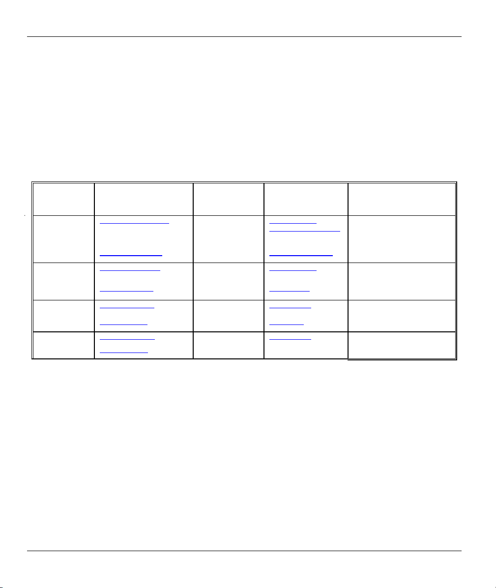
Windows 95/98/Me
Click Start, Settings, Control Panel and double-click the
Network icon to open the Network window.
Setting Up Your Computer’s IP Address 1-1
Page 18

ZyWALL 10~100 Series Internet Security Gateway
The Network window Configuration tab displays a list of installed components. You need a network
adapter, the TCP/IP protocol and Client for Microsoft Networks.
If you need the adapter:
In the Network window, click Add.
a.
Select Adapter and then click Add.
b.
Select the manufacturer and model of your network adapter and then click OK.
c.
If you need TCP/IP:
In the Network window, click Add.
a.
Select Protocol and then click Add.
b.
Select Microsoft from the list of manufacturers.
c.
Select TCP/IP from the list of network protocols and then click OK.
d.
If you need Client for Microsoft Networks:
Click Add.
a.
Select Client and then click Add.
b.
Select Microsoft from the list of manufacturers.
c.
Select Client for Microsoft Networks from the list of network clients and then click OK.
d.
e. Restart your computer so the changes you made take effect.
In the Network window Configuration tab, select your network adapter's TCP/IP entry and click
Properties.
1-2
Setting Up Your Computer’s IP Address
Page 19
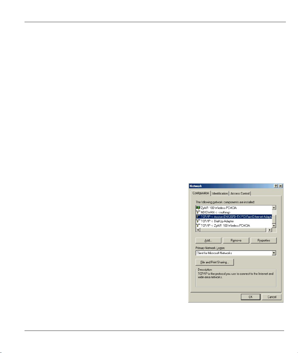
Click the IP Address tab.
1.
-If your IP address is dynamic, select Obtain an
IP address automatically.
-If you have a static IP address, select Specify
an IP address and type your information into
the IP Address and Subnet Mask fields.
Click the DNS Configuration tab.
2.
-If you do not know your DNS information, select
Disable DNS.
-If you know your DNS information, select
Enable DNS and type the information in the
fields below (you may not need to fill them all
in).
ZyWALL 10~100 Series Internet Security Gateway
Setting Up Your Computer’s IP Address 1-3
Page 20

ZyWALL 10~100 Series Internet Security Gateway
Click the Gateway tab.
3.
-If you do not know your gateway’s IP address,
remove previously installed gateways.
-If you have a gateway IP address, type it in the
New gateway field and click Add.
Click OK to save and close the TCP/IP Properties window.
4.
Click OK to close the Network window. Insert the Windows CD if prompted.
5.
6. Turn on your ZyWALL and restart your computer when prompted.
Verifying Your Computer’s IP Address
Click Start and then Run.
1.
In the Run window, type "winipcfg" and then click OK to open the IP Configuration window.
2.
3. Select your network adapter. You should see your computer's IP address, subnet mask and default
gateway.
Windows 2000/NT/XP
1-4
Setting Up Your Computer’s IP Address
Page 21
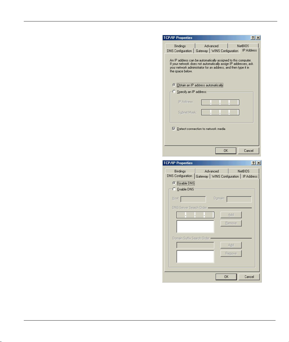
For Windows XP, click start, Control Panel. In
1.
Windows 2000/NT, click Start, Settings, Control
Panel.
ZyWALL 10~100 Series Internet Security Gateway
For Windows XP, click Network
2.
Connections. For Windows 2000/NT, click
Network and Dial-up Connections.
Right-click Local Area Connection and
3.
then click Properties.
Setting Up Your Computer’s IP Address 1-5
Page 22

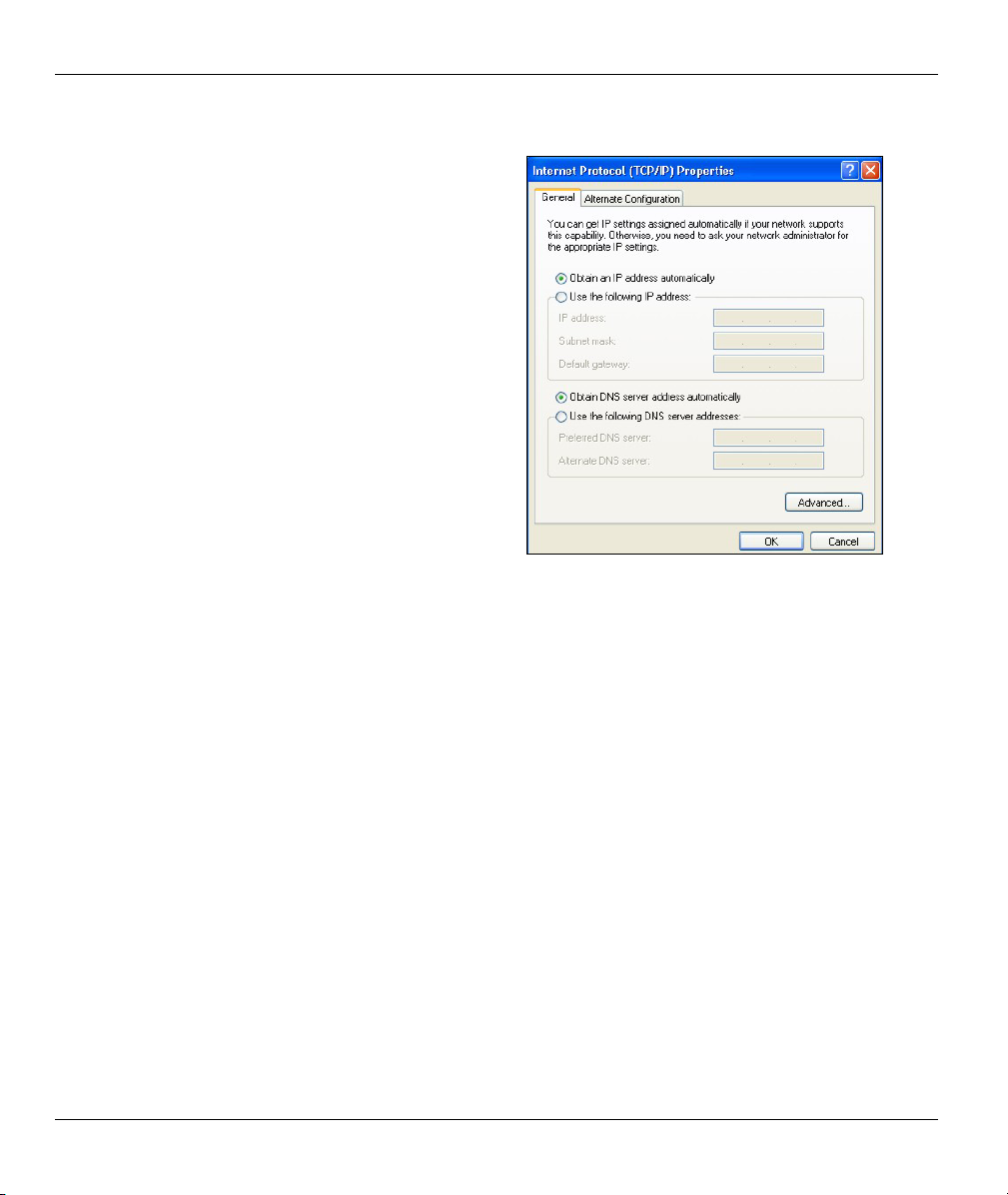
ZyWALL 10~100 Series Internet Security Gateway
Select Internet Protocol (TCP/IP) (under the
4.
General tab in Win XP) and click Properties.
The Internet Protocol TCP/IP Properties
5.
window opens (the General tab in Windows XP).
-If you have a dynamic IP address click Obtain
an IP address automatically.
-If you have a static IP address click Use the
following IP Address and fill in the IP address,
Subnet mask, and Default gateway fields.
Click Advanced.
1-6
Setting Up Your Computer’s IP Address
Page 23
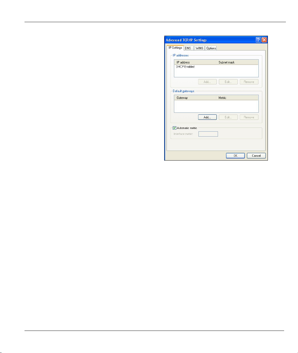
ZyWALL 10~100 Series Internet Security Gateway
6. -If you do not know your gateway's IP address,
remove any previously installed gateways in the
IP Settings tab and click OK.
Do one or more of the following if you want to
configure additional IP addresses:
-In the IP Settings tab, in IP addresses, click
Add.
-In TCP/IP Address, type an IP address in IP
address and a subnet mask in Subnet mask,
and then click Add.
-Repeat the above two steps for each IP address
you want to add.
-Configure additional default gateways in the IP
Settings tab by clicking Add in Default
gateways.
-In TCP/IP Gateway Address, type the IP
address of the default gateway in Gateway. To
manually configure a default metric (the number
of transmission hops), clear the Automatic
metric check box and type a metric in Metric.
-Click Add.
-Repeat the previous three steps for each default gateway you want to add.
-Click OK when finished.
Setting Up Your Computer’s IP Address 1-7
Page 24
ZyWALL 10~100 Series Internet Security Gateway
In the Internet Protocol TCP/IP Properties
7.
window (the General tab in Windows XP):
-Click Obtain DNS server address
automatically if you do not know your DNS
server IP address(es).
-If you know your DNS server IP address(es),
click Use the following DNS server addresses,
and type them in the Preferred DNS server and
Alternate DNS server fields.
If you have previously configured DNS servers,
click Advanced and then the DNS tab to order
them.
Click OK to close the Internet Protocol (TCP/IP) Properties window.
8.
Click OK to close the Local Area Connection Properties window.
9.
10. Turn on your ZyWALL and restart your computer (if prompted).
Verifying Your Computer’s IP Address
Click Start, All Programs, Accessories and then Command Prompt.
1.
In the Command Prompt window, type "ipconfig" and then press [ENTER]. You can also open
2.
Network Connections, right-click a network connection, click Status and then click the Support tab.
Macintosh OS 8/9
1-8
Setting Up Your Computer’s IP Address
Page 25
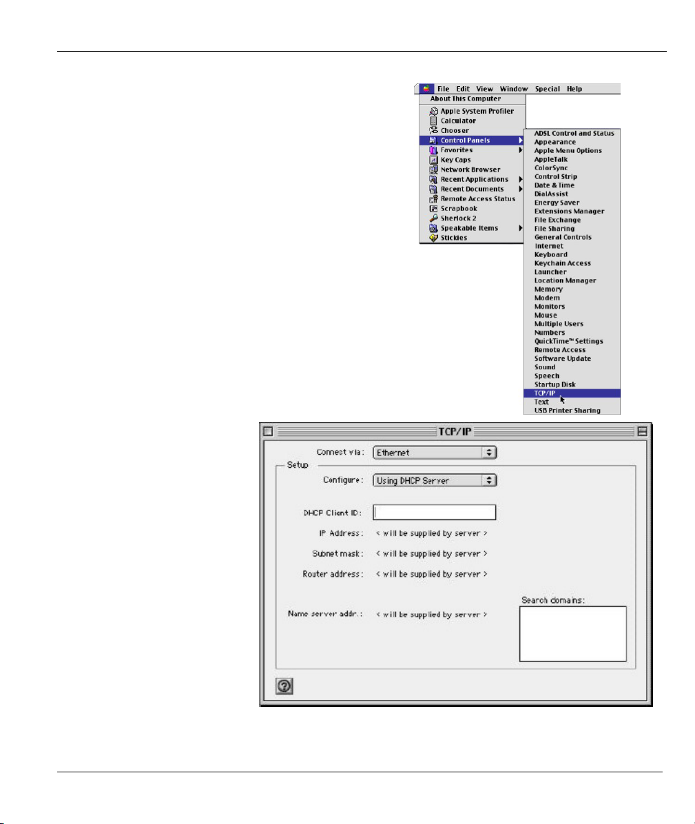
Click the Apple menu, Control Panel and double-click
1.
TCP/IP to open the TCP/IP Control Panel.
Select Ethernet built-in
2.
from the Connect via list.
ZyWALL 10~100 Series Internet Security Gateway
For dynamically assigned settings, select Using DHCP Server from the Configure: list.
3.
Setting Up Your Computer’s IP Address 1-9
Page 26
ZyWALL 10~100 Series Internet Security Gateway
4. For statically assigned settings, do the following:
-From the Configure box, select Manually.
-Type your IP address in the IP Address box.
-Type your subnet mask in the Subnet mask box.
-Type the IP address of your ZyWALL in the Router address box.
Close the TCP/IP Control Panel.
5.
Click Save if prompted, to save changes to your configuration.
6.
7. Turn on your ZyWALL and restart your computer (if prompted).
Verifying Your Computer’s IP Address
Check your TCP/IP properties in the TCP/IP Control Panel window.
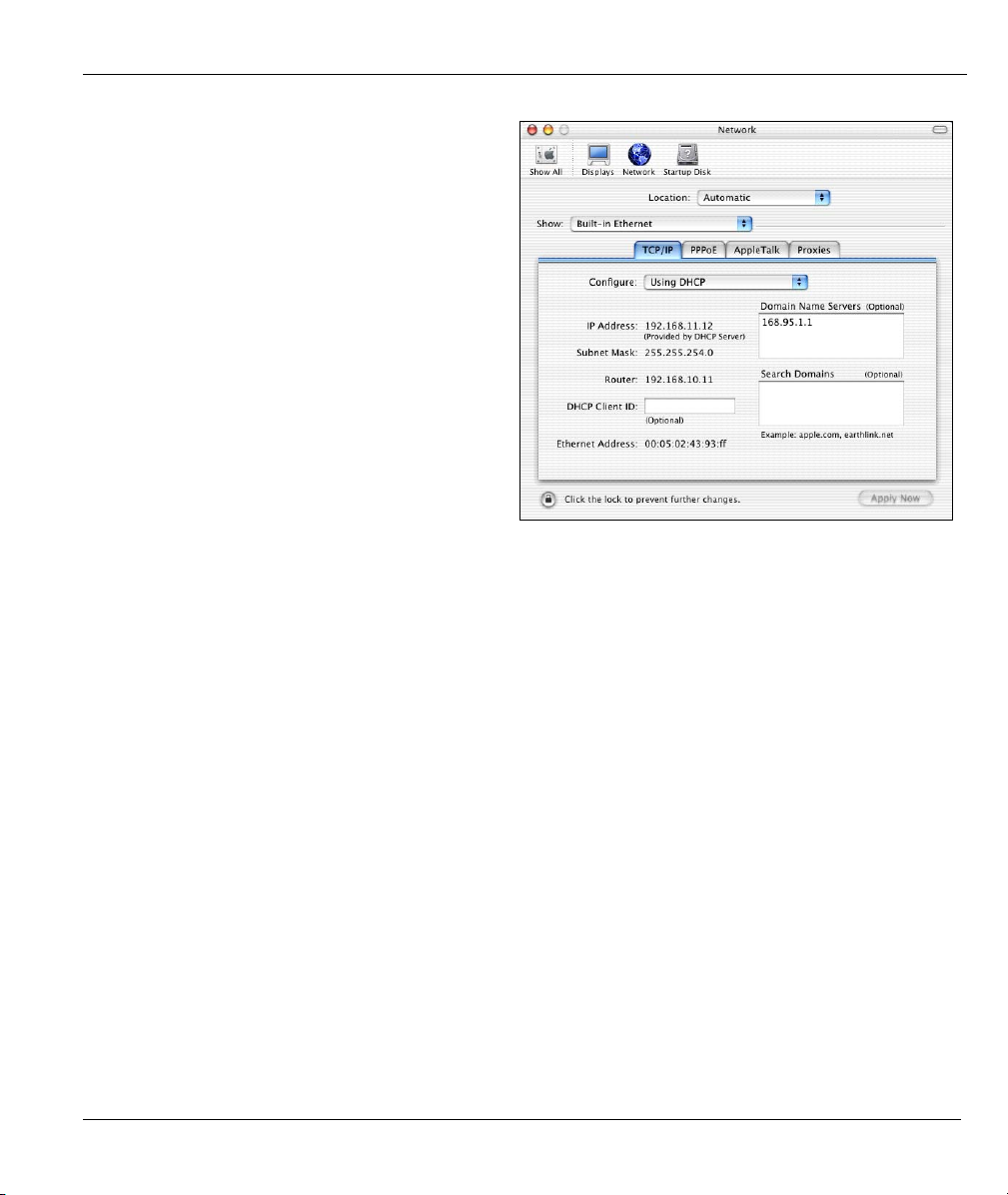
Macintosh OS X
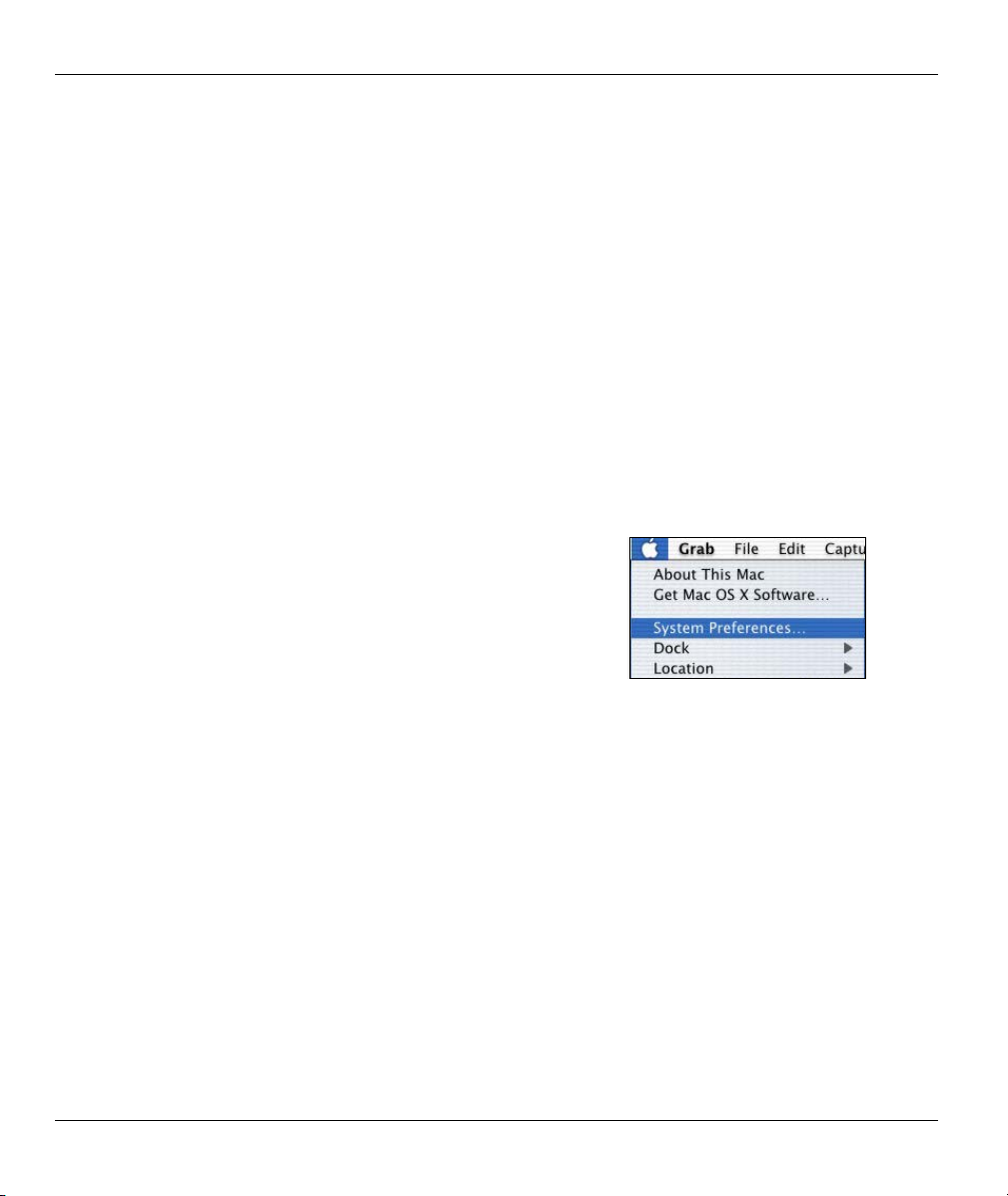
Click the Apple menu, and click System Preferences
1.
to open the System Preferences window.
1-10
Setting Up Your Computer’s IP Address
Page 27
ZyWALL 10~100 Series Internet Security Gateway
2.
Click Network in the icon bar.
- Select Automatic from the Location list.
- Select Built-in Ethernet from the Show list.
- Click the TCP/IP tab.
3.
For dynamically assigned settings, select Using DHCP from the Configure list.
4. For statically assigned settings, do the following:
-From the Configure box, select Manually.
-Type your IP address in the IP Address box.
-Type your subnet mask in the Subnet mask box.
-Type the IP address of your ZyWALL in the Router address box.
Click Apply Now and close the window.
5.
6. Turn on your ZyWALL and restart your computer (if prompted).
Verifying Your Computer’s IP Address
Check your TCP/IP properties in the Network window.
Setting Up Your Computer’s IP Address 1-11
Page 28

Page 29
ZyWALL 10~100 Series Internet Security Gateway
Chapter 2
Triangle Route
The Ideal Setup
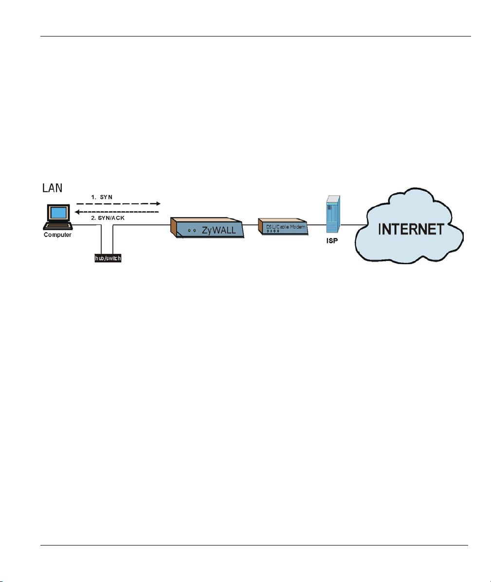
When the firewall is on, your ZyWALL acts as a secure gateway between your LAN and the Internet. In an
ideal network topology, all incoming and outgoing network traffic passes through the ZyWALL to protect
your LAN against attacks.
Diagram 2-1 Ideal Setup
The “Triangle Route” Problem
A traffic route is a path for sending or receiving data packets between two Ethernet devices. Some companies
have more than one alternate route to one or more ISPs. If the LAN and ISP(s) are in the same subnet, the
“triangle route” problem may occur. The steps below describe the “triangle route” problem.
Step 1. A computer on the LAN initiates a connection by sending out a SYN packet to a receiving server
on the WAN.
Step 2. The ZyWALL reroutes the SYN packet through Gateway B on the LAN to the WAN.
Step 3. The reply from the WAN goes directly to the computer on the LAN without going through the
ZyWALL.
As a result, the ZyWALL resets the connection, as the connection has not been acknowledged.
Triangle Route 2-1
Page 30

ZyWALL 10~100 Series Internet Security Gateway
Diagram 2-2 “Triangle Route” Problem
The “Triangle Route” Solutions
This section presents you two solutions to the “triangle route” problem.
IP Aliasing
IP alias allows you to partition your network into logical sections over the same Ethernet interface. Your
ZyWALL supports up to three logical LAN interfaces with the ZyWALL being the gateway for each logical
network. By putting your LAN and Gateway B in different subnets, all returning network traffic must pass
through the ZyWALL to your LAN. The following steps describe such a scenario.
Step 1. A computer on the LAN initiates a connection by sending a SYN packet to a receiving server on
the WAN.
Step 2. The ZyWALL reroutes the packet to Gateway B which is in Subnet 2.
Step 3. The reply from WAN goes through the ZyWALL to the computer on the LAN in Subnet 1.
Diagram 2-3 IP Alias
2-2
Triangle Route
Page 31

ZyWALL 10~100 Series Internet Security Gateway
Gateways on the WAN Side
A second solution to the “triangle route” problem is to put all of your network gateways on the WAN side as
the following figure shows. This ensures that all incoming network traffic passes through your ZyWALL to
your LAN. Therefore your LAN is protected.
Diagram 2-4 Gateways on the WAN Side
Triangle Route 2-3
Page 32

Page 33

ZyWALL 10~100 Series Internet Security Gateway
Chapter 3
The Big Picture
The following figure gives an overview of how filtering, the firewall, VPN and NAT are related.
Diagram 3-1 Big Picture— Filtering, Firewall, VPN and NAT
The Big Picture 3-1
Page 34

ZyWALL 10~100 Series Internet Security Gateway
3-2
The Big Picture
Page 35

ZyWALL 10~100 Series Internet Security Gateway
Chapter 4
Wireless LAN and IEEE 802.11
A wireless LAN (WLAN) provides a flexible data communications system that you can use to access various
services (navigating the Internet, email, printer services, etc.) without the use of a cabled connection. In
effect a wireless LAN environment provides you the freedom to stay connected to the network while roaming
around in the coverage area. WLAN is not available on all models.
Benefits of a Wireless LAN
Wireless LAN offers the following benefits:
1. It provides you with access to network services in areas otherwise hard or expensive to wire, such as
historical buildings, buildings with asbestos materials and classrooms.
2. It provides healthcare workers like doctors and nurses access to a complete patient’s profile on a
handheld or notebook computer upon entering a patient’s room.
3. It allows flexible workgroups a lower total cost of ownership for workspaces that are frequently
reconfigured.
4. It allows conference room users access to the network as they move from meeting to meeting, getting
up-to-date access to information and the ability to communicate decisions while “on the go”.
5. It provides campus-wide networking mobility, allowing enterprises the roaming capability to set up
easy-to-use wireless networks that cover the entire campus transparently.
IEEE 802.11
The 1997 completion of the IEEE 802.11 standard for wireless LANs (WLANs) was a first important step in
the evolutionary development of wireless networking technologies. The standard was developed to maximize
interoperability between differing brands of wireless LANs as well as to introduce a variety of performance
improvements and benefits. On September 16, 1999, the 802.11b provided much higher data rates of up to
11Mbps, while maintaining the 802.11 protocol.
Wireless LAN and IEEE 802.11 4-1
Page 36

ZyWALL 10~100 Series Internet Security Gateway
The IEEE 802.11 specifies three different transmission methods for the PHY, the layer responsible for
transferring data between nodes. Two of the methods use spread spectrum RF signals, Direct Sequence
Spread Spectrum (DSSS) and Frequency-Hopping Spread Spectrum (FHSS), in the 2.4 to 2.4825 GHz
unlicensed ISM (Industrial, Scientific and Medical) band. The third method is infrared technology, using
very high frequencies, just below visible light in the electromagnetic spectrum to carry data.
Ad-hoc Wireless LAN Configuration
The simplest WLAN configuration is an independent (Ad-hoc) WLAN that connects a set of computers with
wireless nodes or stations (STA), which is called a Basic Service Set (BSS). In the most basic form, a
wireless LAN connects a set of computers with wireless adapters. Any time two or more wireless adapters
are within range of each other, they can set up an independent network, which is commonly referred to as an
Ad-hoc network or Independent Basic Service Set (IBSS). See the following diagram of an example of an
Ad-hoc wireless LAN.
4-2
The Big Picture
Page 37

ZyWALL 10~100 Series Internet Security Gateway
Diagram 4-1 Peer-to-Peer Communication in an Ad-hoc Network
Infrastructure Wireless LAN Configuration
For Infrastructure WLANs, multiple Access Points (APs) link the WLAN to the wired network and allow
users to efficiently share network resources. The Access Points not only provide communication with the
wired network but also mediate wireless network traffic in the immediate neighborhood. Multiple Access
Points can provide wireless coverage for an entire building or campus. All communications between stations
or between a station and a wired network client go through the Access Point.
The Extended Service Set (ESS) shown in the next figure consists of a series of overlapping BSSs (each
containing an Access Point) connected together by means of a Distribution System (DS). Although the DS
Wireless LAN and IEEE 802.11 4-3
Page 38

ZyWALL 10~100 Series Internet Security Gateway
could be any type of network, it is almost invariably an Ethernet LAN. Mobile nodes can roam between
Access Points and seamless campus-wide coverage is possible.
Diagram 4-2 ESS Provides Campus-Wide Coverage
4-4
The Big Picture
Page 39

ZyWALL 10~100 Series Internet Security Gateway
Chapter 5
Wireless LAN With IEEE 802.1x
As wireless networks become popular for both portable computing and corporate networks, security is now a
priority.
Security Flaws with IEEE 802.11
Wireless networks based on the original IEEE 802.11 have a poor reputation for safety. The IEEE 802.11b
wireless access standard, first published in 1999, was based on the MAC address. As the MAC address is
sent across the wireless link in clear text, it is easy to spoof and fake. Even the WEP (Wire Equivalent
Privacy) data encryption is unreliable as it can be easily decrypted with current computer speed
Deployment Issues with IEEE 802.11
User account management has become a network administrator’s nightmare in a corporate environment, as
the IEEE 802.11b standard does not provide any central user account management. User access control is
done through manual modification of the MAC address table on the access point. Although WEP data
encryption offers a form of data security, you have to reset the WEP key on the clients each time you change
your WEP key on the access point.
IEEE 802.1x
In June 2001, the IEEE 802.1x standard was designed to extend the features of IEEE 802.11 to support
extended authentication as well as providing additional accounting and control features. It is supported by
Windows XP and a number of network devices.
Advantages of the IEEE 802.1x
• User based identification that allows for roaming.
Wireless LAN with IEEE 802.1x 5-1
Page 40

ZyWALL 10~100 Series Internet Security Gateway
• Support for RADIUS (Remote Authentication Dial In User Service, RFC 2138, 2139) for
centralized user profile and accounting management on a network RADIUS server.
• Support for EAP (Extensible Authentication Protocol, RFC 2486) that allows additional
authentication methods to be deployed with no changes to the access point or the wireless clients.
RADIUS Server Authentication Sequence
The following figure depicts a typical wireless network with a remote RADIUS server for user authentication
using EAPOL (EAP Over LAN).
Client computer
access authorized.
Client computer
access not
authorized.
Diagram 5-1 Sequences for EAP MD5–Challenge Authentication
5-2
Wireless LAN with IEEE 802.1x
Page 41

ZyWALL 10~100 Series Internet Security Gateway
Chapter 6
PPPoE
PPPoE in Action
An ADSL modem bridges a PPP session over Ethernet (PPP over Ethernet, RFC 2516) from your PC to an
ATM PVC (Permanent Virtual Circuit), which connects to a DSL Access Concentrator where the PPP
session terminates (see the next figure). One PVC can support any number of PPP sessions from your LAN.
PPPoE provides access control and billing functionality in a manner similar to dial-up services using PPP.
Benefits of PPPoE
PPPoE offers the following benefits:
1. It provides you with a familiar dial-up networking (DUN) user interface.
2. It lessens the burden on the carriers of provisioning virtual circuits all the way to the ISP on multiple
switches for thousands of users. For GSTN (PSTN & ISDN), the switching fabric is already in place.
3. It allows the ISP to use the existing dial-up model to authenticate and (optionally) to provide
differentiated services.
Traditional Dial-up Scenario
The following diagram depicts a typical hardware configuration where the PCs use traditional dial-up
networking.
Diagram 6-1 Single-PC per Modem Hardware Configuration
PPPoE 6-1
Page 42

ZyWALL 10~100 Series Internet Security Gateway
How PPPoE Works
The PPPoE driver makes the Ethernet appear as a serial link to the PC and the PC runs PPP over it, while the
modem bridges the Ethernet frames to the Access Concentrator (AC). Between the AC and an ISP, the AC is
acting as a L2TP (Layer 2 Tunneling Protocol) LAC (L2TP Access Concentrator) and tunnels the PPP
frames to the ISP. The L2TP tunnel is capable of carrying multiple PPP sessions.
With PPPoE, the VC (Virtual Circuit) is equivalent to the dial-up connection and is between the modem and
the AC, as opposed to all the way to the ISP. However, the PPP negotiation is between the PC and the ISP.
ZyWALL as a PPPoE Client
When using the ZyWALL as a PPPoE client, the PCs on the LAN see only Ethernet and are not aware of
PPPoE. This alleviates the administrator from having to manage the PPPoE clients on the individual PCs.
Diagram 6-2 ZyWALL as a PPPoE Client
6-2 PPPoE
Page 43

ZyWALL 10~100 Series Internet Security Gateway
Chapter 7
PPTP
What is PPTP?
PPTP (Point-to-Point Tunneling Protocol) is a Microsoft proprietary protocol (RFC 2637 for PPTP is
informational only) to tunnel PPP frames.
How can we transport PPP frames from a PC to a broadband
modem over Ethernet?
A solution is to build PPTP into the ANT (ADSL Network Termination) where PPTP is used only over the
short haul between the PC and the modem over Ethernet. For the rest of the connection, the PPP frames are
transported with PPP over AAL5 (RFC 2364). The PPP connection, however, is still between the PC and the
ISP. The various connections in this setup are depicted in the following diagram. The drawback of this
solution is that it requires one separate ATM VC per destination.
Diagram 7-1 Transport PPP frames over Ethernet
PPTP and the ZyWALL
When the ZyWALL is deployed in such a setup, it appears as a PC to the ANT.
In Windows VPN or PPTP Pass-Through feature, the PPTP tunneling is created from Windows 95, 98 and
NT clients to an NT server in a remote location. The pass-through feature allows users on the network to
access a different remote server using the ZyWALL's Internet connection. In NAT mode, the ZyWALL is
able to pass the PPTP packets to the internal PPTP server (i.e. NT server) behind the NAT. Users need to
forward PPTP packets to port 1723 by configuring the server in Menu 15.2 - Server Set Setup. In the case
above as the remote PPTP Client initializes the PPTP connection, the user must configure the PPTP clients.
The ZyWALL initializes the PPTP connection hence; there is no need to configure the remote PPTP clients.
PPTP 7-1
Page 44

ZyWALL 10~100 Series Internet Security Gateway
PPTP Protocol Overview
PPTP is very similar to L2TP, since L2TP is based on both PPTP and L2F (Cisco’s Layer 2 Forwarding).
Conceptually, there are three parties in PPTP, namely the PNS (PPTP Network Server), the PAC (PPTP
Access Concentrator) and the PPTP user. The PNS is the box that hosts both the PPP and the PPTP stacks
and forms one end of the PPTP tunnel. The PAC is the box that dials/answers the phone calls and relays the
PPP frames to the PNS. The PPTP user is not necessarily a PPP client (can be a PPP server too). Both the
PNS and the PAC must have IP connectivity; however, the PAC must in addition have dial-up capability.
The phone call is between the user and the PAC and the PAC tunnels the PPP frames to the PNS. The PPTP
user is unaware of the tunnel between the PAC and the PNS.
Diagram 7-2 PPTP Protocol Overview
Microsoft includes PPTP as a part of the Windows OS. In Microsoft’s implementation, the PC, and hence the
ZyWALL, is the PNS that requests the PAC (the ANT) to place an outgoing call over AAL5 to an RFC 2364
server.
Control & PPP connections
Each PPTP session has distinct control connection and PPP data connection.
Call Connection
The control connection runs over TCP. Similar to L2TP, a tunnel control connection is first established
before call control messages can be exchanged. Please note that a tunnel control connection supports multiple
call sessions.
The following diagram depicts the message exchange of a successful call setup between a PC and an ANT.
7-2 PPTP
Page 45

ZyWALL 10~100 Series Internet Security Gateway
Diagram 7-3 Example Message Exchange between PC and an ANT
PPP Data Connection
The PPP frames are tunneled between the PNS and PAC over GRE (General Routing Encapsulation, RFC
1701, 1702). The individual calls within a tunnel are distinguished using the Call ID field in the GRE header.
PPTP 7-3
Page 46

Page 47

ZyWALL 10~100 Series Internet Security Gateway
Chapter 8
IP Subnetting
IP Addressing
Routers “route” based on the network number. The router that delivers the data packet to the correct
destination host uses the host ID.
IP Classes
An IP address is made up of four octets (eight bits), written in dotted decimal notation, for example,
192.168.1.1. IP addresses are categorized into different classes. The class of an address depends on the value
of its first octet.
Class “A” addresses have a 0 in the left most bit. In a class “A” address the first octet is the network
number and the remaining three octets make up the host ID.
Class “B” addresses have a 1 in the left most bit and a 0 in the next left most bit. In a class “B” address
the first two octets make up the network number and the two remaining octets make up the host ID.
Class “C” addresses begin (starting from the left) with 1 1 0. In a class “C” address the first three octets
make up the network number and the last octet is the host ID.
Class “D” addresses begin with 1 1 1 0. Class “D” addresses are used for multicasting. (There is also a
class “E” address. It is reserved for future use.)
Chart 8-1 Classes of IP Addresses
IP ADDRESS: OCTET 1 OCTET 2 OCTET 3 OCTET 4
Class A 0 Network number Host ID Host ID Host ID
Class B 10 Network number Network number Host ID Host ID
Class C 110 Network number Network number Network number Host ID
Host IDs of all zeros or all ones are not allowed.
Therefore:
A class “C” network (8 host bits) can have 2
IP Subnetting 8-1
8
–2 or 254 hosts.
Page 48

ZyWALL 10~100 Series Internet Security Gateway
A class “B” address (16 host bits) can have 216 –2 or 65534 hosts.
A class “A” address (24 host bits) can have 2
24
–2 hosts (approximately 16 million hosts).
Since the first octet of a class “A” IP address must contain a “0”, the first octet of a class “A” address can
have a value of 0 to 127.
Similarly the first octet of a class “B” must begin with “10”, therefore the first octet of a class “B” address
has a valid range of 128 to 191. The first octet of a class “C” address begins with “110”, and therefore has a
range of 192 to 223.
Chart 8-2 Allowed IP Address Range By Class
CLASS ALLOWED RANGE OF FIRST OCTET
(BINARY)
Class A
Class B
Class C
Class D
00000000 to 01111111
10000000 to 10111111
11000000 to 11011111
11100000 to 11101111
ALLOWED RANGE OF FIRST OCTET
(DECIMAL)
0 to 127
128 to 191
192 to 223
224 to 239
Subnet Masks
A subnet mask is used to determine which bits are part of the network number, and which bits are part of the
host ID (using a logical AND operation). A subnet mask has 32 bits; each bit of the mask corresponds to a bit
of the IP address. If a bit in the subnet mask is a “1” then the corresponding bit in the IP address is part of the
network number. If a bit in the subnet mask is “0” then the corresponding bit in the IP address is part of the
host ID.
Subnet masks are expressed in dotted decimal notation just as IP addresses are. The “natural” masks for class
A, B and C IP addresses are as follows.
Chart 8-3 “Natural” Masks
CLASS NATURAL MASK
A 255.0.0.0
B 255.255.0.0
C 255.255.255.0
Subnetting
8-2 IP Subnetting
Page 49

ZyWALL 10~100 Series Internet Security Gateway
With subnetting, the class arrangement of an IP address is ignored. For example, a class C address no longer
has to have 24 bits of network number and 8 bits of host ID. With subnetting, some of the host ID bits are
converted into network number bits. By convention, subnet masks always consist of a continuous sequence
of ones beginning from the left most bit of the mask, followed by a continuous sequence of zeros, for a total
number of 32 bits.
Since the mask is always a continuous number of ones beginning from the left, followed by a continuous
number of zeros for the remainder of the 32 bit mask, you can simply specify the number of ones instead of
writing the value of each octet. This is usually specified by writing a “/” followed by the number of bits in
the mask after the address.
For example, 192.1.1.0 /25 is equivalent to saying 192.1.1.0 with mask 255.255.255.128.
The following table shows all possible subnet masks for a class “C” address using both notations.
Chart 8-4 Alternative Subnet Mask Notation
SUBNET MASK IP ADDRESS SUBNET MASK “1” BITS LAST OCTET BIT VALUE
255.255.255.0 /24 0000 0000
255.255.255.128 /25 1000 0000
255.255.255.192 /26 1100 0000
255.255.255.224 /27 1110 0000
255.255.255.240 /28 1111 0000
255.255.255.248 /29 1111 1000
255.255.255.252 /30 1111 1100
The first mask shown is the class “C” natural mask. Normally if no mask is specified it is understood that the
natural mask is being used.
Example: Two Subnets
As an example, you have a class “C” address 192.168.1.0 with subnet mask of 255.255.255.0.
NETWORK NUMBER HOST ID
IP Address 192.168.1. 0
IP Address (Binary) 11000000.10101000.00000001. 00000000
Subnet Mask 255.255.255. 0
Subnet Mask (Binary) 11111111.11111111.11111111. 00000000
IP Subnetting 8-3
Page 50

ZyWALL 10~100 Series Internet Security Gateway
The first three octets of the address make up the network number (class “C”). You want to have two separate
networks.
Divide the network 192.168.1.0 into two separate subnets by converting one of the host ID bits of the IP
address to a network number bit. The “borrowed” host ID bit can be either “0” or “1” thus giving two
subnets; 192.168.1.0 with mask 255.255.255.128 and 192.168.1.128 with mask 255.255.255.128.
In the following charts, shaded/bolded last octet bit values indicate host ID bits
“borrowed” to form network ID bits. The number of “borrowed” host ID bits
determines the number of subnets you can have. The remaining number of host ID
bits (after “borrowing”) determines the number of hosts you can have on each
subnet.
Chart 8-5 Subnet 1
NETWORK NUMBER LAST OCTET BIT VALUE
IP Address 192.168.1. 0
IP Address (Binary) 11000000.10101000.00000001.
Subnet Mask 255.255.255. 128
Subnet Mask (Binary) 11111111.11111111.11111111.
Subnet Address: 192.168.1.0 Lowest Host ID: 192.168.1.1
Broadcast Address: 192.168.1.127 Highest Host ID: 192.168.1.126
00000000
10000000
Chart 8-6 Subnet 2
NETWORK NUMBER LAST OCTET BIT VALUE
IP Address 192.168.1. 128
IP Address (Binary) 11000000.10101000.00000001.
Subnet Mask 255.255.255. 128
Subnet Mask (Binary) 11111111.11111111.11111111.
Subnet Address: 192.168.1.128 Lowest Host ID: 192.168.1.129
Broadcast Address: 192.168.1.255 Highest Host ID: 192.168.1.254
10000000
10000000
The remaining 7 bits determine the number of hosts each subnet can have. Host IDs of all zeros represent the
subnet itself and host IDs of all ones are the broadcast address for that subnet, so the actual number of hosts
available on each subnet in the example above is 2
7
– 2 or 126 hosts for each subnet.
8-4 IP Subnetting
Page 51

ZyWALL 10~100 Series Internet Security Gateway
192.168.1.0 with mask 255.255.255.128 is the subnet itself, and 192.168.1.127 with mask 255.255.255.128 is
the directed broadcast address for the first subnet. Therefore, the lowest IP address that can be assigned to an
actual host for the first subnet is 192.168.1.1 and the highest is 192.168.1.126. Similarly the host ID range for
the second subnet is 192.168.1.129 to 192.168.1.254.
Example: Four Subnets
The above example illustrated using a 25-bit subnet mask to divide a class “C” address space into two
subnets. Similarly to divide a class “C” address into four subnets, you need to “borrow” two host ID bits to
give four possible combinations of 00, 01, 10 and 11. The subnet mask is 26 bits
(11111111.11111111.11111111.11000000) or 255.255.255.192. Each subnet contains 6 host ID bits, giving
6
2
-2 or 62 hosts for each subnet (all 0’s is the subnet itself, all 1’s is the broadcast address on the subnet).
Chart 8-7 Subnet 1
NETWORK NUMBER LAST OCTET BIT VALUE
IP Address 192.168.1. 0
IP Address (Binary) 11000000.10101000.00000001.
Subnet Mask (Binary) 11111111.11111111.11111111.
Subnet Address: 192.168.1.0 Lowest Host ID: 192.168.1.1
Broadcast Address: 192.168.1.63 Highest Host ID: 192.168.1.62
00000000
11000000
Chart 8-8 Subnet 2
NETWORK NUMBER LAST OCTET BIT VALUE
IP Address 192.168.1. 64
IP Address (Binary) 11000000.10101000.00000001.
Subnet Mask (Binary) 11111111.11111111.11111111.
Subnet Address: 192.168.1.64 Lowest Host ID: 192.168.1.65
Broadcast Address: 192.168.1.127 Highest Host ID: 192.168.1.126
01000000
11000000
Chart 8-9 Subnet 3
NETWORK NUMBER LAST OCTET BIT VALUE
IP Address 192.168.1. 128
IP Address (Binary) 11000000.10101000.00000001.
Subnet Mask (Binary) 11111111.11111111.11111111.
10000000
11000000
IP Subnetting 8-5
Page 52

ZyWALL 10~100 Series Internet Security Gateway
Subnet Address: 192.168.1.128 Lowest Host ID: 192.168.1.129
Broadcast Address: 192.168.1.191 Highest Host ID: 192.168.1.190
Chart 8-10 Subnet 4
NETWORK NUMBER LAST OCTET BIT VALUE
IP Address 192.168.1. 192
IP Address (Binary) 11000000.10101000.00000001.
Subnet Mask (Binary) 11111111.11111111.11111111.
Subnet Address: 192.168.1.192 Lowest Host ID: 192.168.1.193
Broadcast Address: 192.168.1.255 Highest Host ID: 192.168.1.254
11000000
11000000
Example Eight Subnets
Similarly use a 27-bit mask to create 8 subnets (001, 010, 011, 100, 101, 110).
The following table shows class C IP address last octet values for each subnet.
Chart 8-11 Eight Subnets
SUBNET SUBNET ADDRESS FIRST ADDRESS LAST ADDRESS BROADCAST ADDRESS
1 0 1 30 31
2 32 33 62 63
3 64 65 94 95
4 96 97 126 127
5 128 129 158 159
6 160 161 190 191
7 192 193 222 223
8 224 223 254 255
The following table is a summary for class “C” subnet planning.
8-6 IP Subnetting
Page 53

ZyWALL 10~100 Series Internet Security Gateway
Chart 8-12 Class C Subnet Planning
NO. “BORROWED” HOST BITS SUBNET MASK NO. SUBNETS NO. HOSTS PER SUBNET
1 255.255.255.128 (/25) 2 126
2 255.255.255.192 (/26) 4 62
3 255.255.255.224 (/27) 8 30
4 255.255.255.240 (/28) 16 14
5 255.255.255.248 (/29) 32 6
6 255.255.255.252 (/30) 64 2
7 255.255.255.254 (/31) 128 1
Subnetting With Class A and Class B Networks.
For class “A” and class “B” addresses the subnet mask also determines which bits are part of the network
number and which are part of the host ID.
A class “B” address has two host ID octets available for subnetting and a class “A” address has three host ID
octets (see Chart 8-1) available for subnetting.
The following table is a summary for class “B” subnet planning.
Chart 8-13 Class B Subnet Planning
NO. “BORROWED” HOST BITS SUBNET MASK NO. SUBNETS NO. HOSTS PER SUBNET
1 255.255.128.0 (/17) 2 32766
2 255.255.192.0 (/18) 4 16382
3 255.255.224.0 (/19) 8 8190
4 255.255.240.0 (/20) 16 4094
5 255.255.248.0 (/21) 32 2046
6 255.255.252.0 (/22) 64 1022
7 255.255.254.0 (/23) 128 510
8 255.255.255.0 (/24) 256 254
IP Subnetting 8-7
Page 54

ZyWALL 10~100 Series Internet Security Gateway
Chart 8-13 Class B Subnet Planning
NO. “BORROWED” HOST BITS SUBNET MASK NO. SUBNETS NO. HOSTS PER SUBNET
9 255.255.255.128
(/25)
10 255.255.255.192
(/26)
11 255.255.255.224
(/27)
12 255.255.255.240
(/28)
13 255.255.255.248
(/29)
14 255.255.255.252
(/30)
15 255.255.255.254
(/31)
512 126
1024 62
2048 30
4096 14
8192 6
16384 2
32768 1
8-8 IP Subnetting
Page 55

Command and Log Information
Part II:
Command and Log Information
This part provides information on the command interpreter interface, firewall and NetBIOS
commands and logs and password protection.
II
Page 56

Page 57

ZyWALL 10~100 Series Internet Security Gateway
Chapter 9
Command Interpreter
The following describes how to use the command interpreter. Enter 24 in the main menu to bring up the
system maintenance menu. Enter 8 to go to Menu 24.8 - Command Interpreter Mode. See the included
disk or zyxel.com for more detailed information on these commands.
Use of undocumented commands or misconfiguration can damage the unit and
possibly render it unusable.
Command Syntax
The command keywords are in courier new font.
Enter the command keywords exactly as shown, do not abbreviate.
The required fields in a command are enclosed in angle brackets <>.
The optional fields in a command are enclosed in square brackets [].
The |symbol means “or”.
For example,
sys filter netbios config <type> <on|off>
means that you must specify the type of netbios filter and whether to turn it on or off.
Command Usage
A list of valid commands can be found by typing help or ? at the command prompt. Always type the full
command. Type exit to return to the SMT main menu when finished.
Command Interpreter 9-1
Page 58

Page 59

ZyWALL 10~100 Series Internet Security Gateway
Chapter 10
Firewall Commands
The following describes the firewall commands. See the Command Interpreter appendix for information on
the command structure.
Chart 10-1 Firewall Commands
FUNCTION COMMAND DESCRIPTION
FFiirreewwaallll
SSeett--UUpp
DDiissppllaayy
config edit firewall active
<yes | no>
config retrieve firewall
config save firewall
config display firewall
config display firewall set
<set #>
config display firewall set
<set #> rule <rule #>
This command turns the firewall on or off.
This command returns the previously saved
firewall settings.
This command saves the current firewall
settings.
This command shows the of all the firewall
settings including e-mail, attack, and the sets/
rules.
This command shows the current
configuration of a set; including timeout
values, name, default-permit, and etc.
If you don’t put use a number (#) after “set”,
information about all of the sets/rules appears.
This command shows the current entries of a
rule in a firewall rule set.
Firewall Commands 10-1
Page 60

ZyWALL 10~100 Series Internet Security Gateway
Chart 10-1 Firewall Commands
FUNCTION COMMAND DESCRIPTION
EEddiitt
EE--mmaaiill
config display firewall attack
config display firewall e-mail
config display firewall ?
config edit firewall e-mail
mail-server <ip address of mail
server>
config edit firewall e-mail
return-addr <e-mail address>
config edit firewall e-mail
email-to <e-mail address>
config edit firewall e-mail
policy <full | hourly | daily |
weekly>
config edit firewall e-mail day
<sunday | monday | tuesday |
wednesday | thursday | friday |
saturday>
This command shows all of the attack
response settings.
This command shows all of the e-mail
settings.
This command shows all of the available
firewall sub commands.
This command sets the IP address to which
the e-mail messages are sent.
This command sets the source e-mail address
of the firewall e-mails.
This command sets the e-mail address to
which the firewall e-mails are sent.
This command sets how frequently the firewall
log is sent via e-mail.
This command sets the day on which the
current firewall log is sent through e-mail if the
ZyWALL is set to send it on a weekly basis.
10-2 Firewall Commands
Page 61

ZyWALL 10~100 Series Internet Security Gateway
Chart 10-1 Firewall Commands
FUNCTION COMMAND DESCRIPTION
config edit firewall e-mail
AAttttaacckk
hour <0-23>
config edit firewall e-mail
minute <0-59>
config edit firewall attack
send-alert <yes | no>
config edit firewall attack
block <yes | no>
config edit firewall attack
block-minute <0-255>
config edit firewall attack
minute-high <0-255>
This command sets the hour when the firewall
log is sent through e- mail if the ZyWALL is
set to send it on an hourly, daily or weekly
basis.
This command sets the minute of the hour for
the firewall log to be sent via e- mail if the
ZyWALL is set to send it on a hourly, daily or
weekly basis.
This command enables or disables the
immediate sending of DOS attack notification
e-mail messages.
Set this command to yes to block new traffic
after the tcp-max-incomplete threshold is
exceeded. Set it to no to delete the oldest
half-open session when traffic exceeds the
tcp-max-incomplete threshold.
This command sets the number of minutes for
new sessions to be blocked when the tcpmax-incomplete threshold is reached. This
command is only valid when block is set to
yes.
This command sets the threshold rate of new
half-open sessions per minute where the
ZyWALL starts deleting old half-opened
sessions until it gets them down to the minutelow threshold.
Firewall Commands 10-3
Page 62

ZyWALL 10~100 Series Internet Security Gateway
Chart 10-1 Firewall Commands
FUNCTION COMMAND DESCRIPTION
config edit firewall attack
minute-low <0-255>
config edit firewall attack
max-incomplete-high <0-255>
config edit firewall attack
max-incomplete-low <0-255>
config edit firewall attack
tcp-max-incomplete <0-255>
config edit firewall set <set
SSeettss
#> name <desired name>
Config edit firewall set <set
#> default-permit <forward |
block>
Config edit firewall set <set
#> icmp-timeout <seconds>
Config edit firewall set <set
#> udp-idle-timeout <seconds>
This command sets the threshold of half-open
sessions where the ZyWALL stops deleting
half-opened sessions.
This command sets the threshold of half-open
sessions where the ZyWALL starts deleting
old half-opened sessions until it gets them
down to the max incomplete low.
This command sets the threshold where the
ZyWALL stops deleting half-opened sessions.
This command sets the threshold of half-open
TCP sessions with the same destination
where the ZyWALL starts dropping half-open
sessions to that destination.
This command sets a name to identify a
specified set.
This command sets whether a packet is
dropped or allowed through, when it does not
meet a rule within the set.
This command sets the time period to allow
an ICMP session to wait for the ICMP
response.
This command sets how long a UDP
connection is allowed to remain inactive
before the ZyWALL considers the connection
closed.
10-4 Firewall Commands
Page 63

ZyWALL 10~100 Series Internet Security Gateway
Chart 10-1 Firewall Commands
FUNCTION COMMAND DESCRIPTION
RRuulleess
Config edit firewall set <set
#> connection-timeout <seconds>
Config edit firewall set <set
#> fin-wait-timeout <seconds>
Config edit firewall set <set
#> tcp-idle-timeout <seconds>
Config edit firewall set <set
#> log <yes | no>
Config edit firewall set <set
#> rule <rule #> permit
<forward | block>
Config edit firewall set <set
#> rule <rule #> active <yes |
no>
Config edit firewall set <set
#> rule <rule #> protocol
<integer protocol value >
Config edit firewall set <set
#> rule <rule #> log <none |
match | not-match | both>
This command sets how long ZyWALL waits
for a TCP session to be established before
dropping the session.
This command sets how long the ZyWALL
leaves a TCP session open after the firewall
detects a FIN-exchange (indicating the end of
the TCP session).
This command sets how long ZyWALL lets an
inactive TCP connection remain open before
considering it closed.
This command sets whether or not the
ZyWALL creates logs for packets that match
the firewall’s default rule set.
This command sets whether packets that
match this rule are dropped or allowed
through.
This command sets whether a rule is enabled
or not.
This command sets the protocol specification
number made in this rule for ICMP.
This command sets the ZyWALL to log traffic
that matches the rule, doesn't match, both or
neither.
Firewall Commands 10-5
Page 64

ZyWALL 10~100 Series Internet Security Gateway
Chart 10-1 Firewall Commands
FUNCTION COMMAND DESCRIPTION
Config edit firewall set <set
#> rule <rule #> alert <yes |
no>
config edit firewall set <set
#> rule <rule #> srcaddr-single
<ip address>
config edit firewall set <set
#> rule <rule #> srcaddr-subnet
<ip address> <subnet mask>
config edit firewall set <set
#> rule <rule #> srcaddr-range
<start ip address> <end ip
address>
config edit firewall set <set
#> rule <rule #> destaddrsingle <ip address>
config edit firewall set <set
#> rule <rule #> destaddrsubnet <ip address> <subnet
mask>
config edit firewall set <set
#> rule <rule #> destaddr-range
<start ip address> <end ip
address>
This command sets whether or not the
ZyWALL sends an alert e-mail when a DOS
attack or a violation of a particular rule occurs.
This command sets the rule to have the
ZyWALL check for traffic with this individual
source address.
This command sets a rule to have the
ZyWALL check for traffic from a particular
subnet (defined by IP address and subnet
mask).
This command sets a rule to have the
ZyWALL check for traffic from this range of
addresses.
This command sets the rule to have the
ZyWALL check for traffic with this individual
destination address.
This command sets a rule to have the
ZyWALL check for traffic with a particular
subnet destination (defined by IP address and
subnet mask).
This command sets a rule to have the
ZyWALL check for traffic going to this range of
addresses.
10-6 Firewall Commands
Page 65

ZyWALL 10~100 Series Internet Security Gateway
Chart 10-1 Firewall Commands
FUNCTION COMMAND DESCRIPTION
DDeelleettee
config edit firewall set <set
#> rule <rule #> TCP destportsingle <port #>
config edit firewall set <set
#> rule <rule #> TCP destportrange <start port #> <end port
#>
config edit firewall set <set
#> rule <rule #> UDP destportsingle <port #>
config edit firewall set <set
#> rule <rule #> UDP destportrange <start port #> <end port
#>
config delete firewall e-mail
config delete firewall attack
config delete firewall set <set
#>
This command sets a rule to have the
ZyWALL check for TCP traffic with this
destination address. You may repeat this
command to enter various, non-consecutive
port numbers.
This command sets a rule to have the
ZyWALL check for TCP traffic with a
destination port in this range.
This command sets a rule to have the
ZyWALL check for UDP traffic with this
destination address. You may repeat this
command to enter various, non-consecutive
port numbers.
This command sets a rule to have the
ZyWALL check for UDP traffic with a
destination port in this range.
This command removes all of the settings for
e-mail alert.
This command resets all of the attack
response settings to their defaults.
This command removes the specified set from
the firewall configuration.
Firewall Commands 10-7
Page 66

ZyWALL 10~100 Series Internet Security Gateway
Chart 10-1 Firewall Commands
FUNCTION COMMAND DESCRIPTION
config delete firewall set <set
#> rule
<rule #>
This command removes the specified rule in a
firewall configuration set.
10-8 Firewall Commands
Page 67

ZyWALL 10~100 Series Internet Security Gateway
Chapter 11
NetBIOS Filter Commands
The following describes the NetBIOS packet filter commands. See the Command Interpreter appendix for
information on the command structure.
Introduction
NetBIOS (Network Basic Input/Output System) are TCP or UDP broadcast packets that enable a computer to
connect to and communicate with a LAN.
For some dial-up services such as PPPoE or PPTP, NetBIOS packets cause unwanted calls.
You can configure NetBIOS filters to do the following (filters for DMZ are not available on all models):
• Allow or disallow the sending of NetBIOS packets from the LAN to the WAN.
• Allow or disallow the sending of NetBIOS packets from the WAN to the LAN.
• Allow or disallow the sending of NetBIOS packets from the LAN to the DMZ.
• Allow or disallow the sending of NetBIOS packets from the WAN to the DMZ.
• Allow or disallow the sending of NetBIOS packets from the DMZ to the LAN.
• Allow or disallow the sending of NetBIOS packets from the DMZ to the WAN.
• Allow or disallow the sending of NetBIOS packets through VPN connections.
• Allow or disallow NetBIOS packets to initiate calls.
Display NetBIOS Filter Settings
Syntax:
NetBIOS Filter Commands 11-1
sys filter netbios disp
Page 68

ZyWALL 10~100 Series Internet Security Gateway
This command gives a read-only list of the current NetBIOS filter modes for a ZyWALL that does not
have DMZ.
=============== NetBIOS Filter Status ===============
LAN to WAN: Forward
WAN to LAN: Forward
IPSec Packets: Forward
Trigger Dial: Disabled
Diagram 11-1 NetBIOS Display Filter Settings Command Without DMZ Example
Syntax:
sys filter netbios disp
This command gives a read-only list of the current NetBIOS filter modes for a ZyWALL that has DMZ.
=============== NetBIOS Filter Status ===============
LAN to WAN: Forward
WAN to LAN: Forward
LAN to DMZ: Forward
WAN to DMZ: Forward
DMZ to LAN: Forward
DMZ to WAN: Forward
IPSec Packets: Forward
Trigger Dial: Disabled
Diagram 11-2 NetBIOS Display Filter Settings Command With DMZ Example
The filter types and their default settings are as follows.
Chart 11-1 NetBIOS Filter Default Settings
NAME DESCRIPTION EXAMPLE
LAN to WAN This field displays whether NetBIOS packets are blocked or forwarded
from the LAN to the WAN.
WAN to LAN This field displays whether NetBIOS packets are blocked or forwarded
from the WAN to the LAN.
LAN to DMZ This field displays whether NetBIOS packets are blocked or forwarded
from the LAN to the DMZ.
Forward
Forward
Forward
11-2 NetBIOS Filter Commands
Page 69

ZyWALL 10~100 Series Internet Security Gateway
Chart 11-1 NetBIOS Filter Default Settings
NAME DESCRIPTION EXAMPLE
WAN to DMZ This field displays whether NetBIOS packets are blocked or forwarded
from the WAN to the DMZ.
DMZ to LAN This field displays whether NetBIOS packets are blocked or forwarded
from the DMZ to the LAN.
DMZ to WAN This field displays whether NetBIOS packets are blocked or forwarded
from the DMZ to the WAN.
IPSec
Packets
Trigger dial This field displays whether NetBIOS packets are allowed to initiate
This field displays whether NetBIOS packets sent through a VPN
connection are blocked or forwarded.
calls. Disabled means that NetBIOS packets are blocked from initiating
calls.
Forward
Forward
Forward
Forward
Disabled
NetBIOS Filter Configuration
Syntax:
sys filter netbios config <type> <on|off>
where
<type> =
Identify which NetBIOS filter (numbered 0-3) to configure.
0 = LAN to WAN
1 = WAN to LAN
2 =LAN to DMZ
3 = WAN to DMZ
4 = DMZ to LAN
5 = DMZ to WAN
6 = IPSec packet pass through
7 = Trigger Dial
NetBIOS Filter Commands 11-3
Page 70

ZyWALL 10~100 Series Internet Security Gateway
<on|off> = For types 0 and 1, use on to enable the filter and block NetBIOS packets. Use off to
disable the filter and forward NetBIOS packets.
For type 6, use on to block NetBIOS packets from being sent through a VPN
connection. Use off to allow NetBIOS packets to be sent through a VPN connection.
For type 7, use on to allow NetBIOS packets to initiate dial backup calls. Use off to
block NetBIOS packets from initiating dial backup calls.
Example commands
Command:
sys filter netbios config 0 on
This command blocks LAN to WAN NetBIOS packets
Command:
sys filter netbios config 1 off
This command forwards WAN to LAN NetBIOS packets
Command:
sys filter netbios config 6 on
This command blocks IPSec NetBIOS packets
Command:
sys filter netbios config 7 off
This command stops NetBIOS commands from initiating calls.
11-4 NetBIOS Filter Commands
Page 71

ZyWALL 10~100 Series Internet Security Gateway
Chapter 12
Boot Commands
The BootModule AT commands execute from within the router’s bootup software, when debug mode is
selected before the main router firmware (ZyNOS) is started. When you start up your ZyWALL, you are
given a choice to go into debug mode by pressing a key at the prompt shown in the following screen. In
debug mode you have access to a series of boot module commands, for example
firmware) and
and Configuration File Maintenance chapter.
Enter
ATHE to view all available ZyWALL boot module commands as shown in the next screen. ATBAx
allows you to change the console port speed. The x denotes the number preceding the colon to give the
console port speed following the colon in the list of numbers that follows; for example
console port speed of 9.6 Kbps.
debug flag in the firmware. The
version, vendor name, product model, RAS code revision, etc.
system. Most other commands aid in advanced troubleshooting and should only be used by qualified
engineers.
ATLC (for uploading the configuration file). These are already discussed in the Firmware
Bootbase Version: V1.02 | 08/08/2001 15:40:50
RAM: Size = 16384 Kbytes
DRAM Post: Testing: 16384K OK
FLASH: Intel 16M
ZyNOS Version: V3.50(WB.0)b3 | 08/08/2001 16:21:27
Press any key to enter debug mode within 3 seconds.
Diagram 12-1 Option to Enter Debug Mode
ATSE displays the seed that is used to generate a password to turn on the
ATSH command shows product related information such as boot module
ATGO allows you to continue booting the
ATUR (for uploading
ATBA3 will give a
Boot Commands 12-1
Page 72

ZyWALL 10~100 Series Internet Security Gateway
AT just answer OK
ATHE print help
ATBAx change baudrate. 1:38.4k, 2:19.2k, 3:9.6k 4:57.6k 5:115.2k
ATENx,(y) set BootExtension Debug Flag (y=password)
ATSE show the seed of password generator
ATTI(h,m,s) change system time to hour:min:sec or show current time
ATDA(y,m,d) change system date to year/month/day or show current date
ATDS dump RAS stack
ATDT dump Boot Module Common Area
ATDUx,y dump memory contents from address x for length y
ATRBx display the 8-bit value of address x
ATRWx display the 16-bit value of address x
ATRLx display the 32-bit value of address x
ATGO(x) run program at addr x or boot router
ATGR boot router
ATGT run Hardware Test Program
ATRTw,x,y(,z) RAM test level w, from address x to y (z iterations)
ATSH dump manufacturer related data in ROM
ATDOx,y download from address x for length y to PC via XMODEM
ATTD download router configuration to PC via XMODEM
ATUR upload router firmware to flash ROM
ATLC upload router configuration file to flash ROM
ATXSx xmodem select: x=0: CRC mode(default); x=1: checksum mode
ATSR system reboot
Diagram 12-2 Boot Module Commands
12-2 Boot Commands
Page 73

LOG MESSAGE DESCRIPTION
%s exceeds the max.
number of session per
host!
LOG MESSAGE DESCRIPTION
Time calibration is
successful
ZyWALL 10~100 Series Internet Security Gateway
Chapter 13
Log Descriptions
Chart 13-1 System Error Logs
This attempt to create a NAT session exceeds the maximum number of
NAT session table entries allowed to be created per host.
Chart 13-2 System Maintenance Logs
The router has adjusted its time based on information from the time
server.
Time calibration
failed
DHCP client gets %s
DHCP client IP
expired
DHCP server assigns
%s
SMT Login
Successfully
SMT Login Fail
WEB Login
Successfully
WEB Login Fail
TELNET Login
Successfully
Log Descriptions 13-1
The router failed to get information from the time server.
A DHCP client got a new IP address from the DHCP server.
A DHCP client's IP address has expired.
The DHCP server assigned an IP address to a client.
Someone has logged on to the router's SMT interface.
Someone has failed to log on to the router's SMT interface.
Someone has logged on to the router's web configurator interface.
Someone has failed to log on to the router's web configurator interface.
Someone has logged on to the router via telnet.
Page 74

ZyWALL 10~100 Series Internet Security Gateway
Chart 13-2 System Maintenance Logs
TELNET Login Fail
FTP Login
Someone has failed to log on to the router via telnet.
Someone has logged on to the router via ftp.
Successfully
FTP Login Fail
NAT Session Table is
Full!
Someone has failed to log on to the router via ftp.
The maximum number of NAT session table entries has been
exceeded and the table is full.
Chart 13-3 UPnP Logs
LOG MESSAGE DESCRIPTION
UPnP pass through
UPnP packets can pass through the firewall.
Firewall
Chart 13-4 Content Filtering Logs
CATEGORY LOG MESSAGE DESCRIPTION
URLFOR
URLBLK
JAVBLK
IP/Domain Name
IP/Domain Name
IP/Domain Name
The ZyWALL allows access to this IP address or domain
name and forwarded traffic addressed to the IP address or
domain name.
The ZyWALL blocked access to this IP address or domain
name due to a forbidden keyword. All web traffic is disabled
except for trusted domains, untrusted domains, or the
cybernot list.
The ZyWALL blocked access to this IP address or domain
name because of a forbidden service such as: ActiveX, a
Java applet, a cookie, or a proxy.
Chart 13-5 Attack Logs
LOG MESSAGE DESCRIPTION
attack TCP
attack UDP
The firewall detected a TCP attack.
The firewall detected an UDP attack.
13-2 Log Descriptions
Page 75

LOG MESSAGE DESCRIPTION
attack IGMP
ZyWALL 10~100 Series Internet Security Gateway
Chart 13-5 Attack Logs
The firewall detected an IGMP attack.
attack ESP
attack GRE
attack OSPF
attack ICMP (type:%d,
code:%d)
land TCP
land UDP
land IGMP
land ESP
land GRE
land OSPF
land ICMP (type:%d,
code:%d)
ip spoofing - WAN TCP
ip spoofing - WAN UDP
ip spoofing - WAN
IGMP
ip spoofing - WAN ESP
The firewall detected an ESP attack.
The firewall detected a GRE attack.
The firewall detected an OSPF attack.
The firewall detected an ICMP attack; see the section on ICMP
messages for type and code details.
The firewall detected a TCP land attack.
The firewall detected an UDP land attack.
The firewall detected an IGMP land attack.
The firewall detected an ESP land attack.
The firewall detected a GRE land attack.
The firewall detected an OSPF land attack.
The firewall detected an ICMP land attack; see the section on ICMP
messages for type and code details.
The firewall detected a TCP IP spoofing attack on the WAN port.
The firewall detected an UDP IP spoofing attack on the WAN port.
The firewall detected an IGMP IP spoofing attack on the WAN port.
The firewall detected an ESP IP spoofing attack on the WAN port.
ip spoofing - WAN GRE
ip spoofing - WAN
The firewall detected a GRE IP spoofing attack on the WAN port.
The firewall detected an OSPF IP spoofing attack on the WAN port.
OSPF
ip spoofing - WAN
ICMP (type:%d,
The firewall detected an ICMP IP spoofing attack on the WAN port.
See the section on ICMP messages for type and code details.
code:%d)
icmp echo ICMP
(type:%d, code:%d)
The firewall detected an ICMP echo attack. See the section on ICMP
messages for type and code details.
Log Descriptions 13-3
Page 76

ZyWALL 10~100 Series Internet Security Gateway
Chart 13-5 Attack Logs
LOG MESSAGE DESCRIPTION
syn flood TCP
The firewall detected a TCP syn flood attack.
ports scan TCP
teardrop TCP
teardrop UDP
teardrop ICMP
(type:%d, code:%d)
illegal command TCP
NetBIOS TCP
ip spoofing - no
routing entry TCP
ip spoofing - no
routing entry UDP
ip spoofing - no
routing entry IGMP
ip spoofing - no
routing entry ESP
ip spoofing - no
routing entry GRE
ip spoofing - no
routing entry OSPF
The firewall detected a TCP port scan attack.
The firewall detected a TCP teardrop attack.
The firewall detected an UDP teardrop attack.
The firewall detected an ICMP teardrop attack; see the section on
ICMP messages for type and code details.
The firewall detected a TCP illegal command attack.
The firewall detected a TCP NetBIOS attack.
The firewall detected a TCP IP spoofing attack while the ZyWALL did
not have a default route.
The firewall detected an UDP IP spoofing attack while the ZyWALL did
not have a default route.
The firewall detected an IGMP IP spoofing attack while the ZyWALL
did not have a default route.
The firewall detected an ESP IP spoofing attack while the ZyWALL did
not have a default route.
The firewall detected a GRE IP spoofing attack while the ZyWALL did
not have a default route.
The firewall detected an OSPF IP spoofing attack while the ZyWALL
did not have a default route.
ip spoofing - no
routing entry ICMP
(type:%d, code:%d)
vulnerability ICMP
(type:%d, code:%d)
traceroute ICMP
(type:%d, code:%d)
The firewall detected an ICMP IP spoofing attack while the ZyWALL
did not have a default route; see the section on ICMP messages for
type and code details.
The firewall detected an ICMP vulnerability attack; see the section on
ICMP messages for type and code details.
The firewall detected an ICMP traceroute attack; see the section on
ICMP messages for type and code details.
13-4 Log Descriptions
Page 77

LOG MESSAGE DESCRIPTION
Firewall default
policy: TCP (set:%d)
Firewall default
policy: UDP (set:%d)
Firewall default
policy: ICMP (set:%d,
type:%d, code:%d)
Firewall default
policy: IGMP (set:%d)
Firewall default
policy: ESP (set:%d)
Firewall default
policy: GRE (set:%d)
Firewall default
policy: OSPF (set:%d)
Firewall default
policy: (set:%d)
Firewall rule match:
TCP (set:%d, rule:%d)
ZyWALL 10~100 Series Internet Security Gateway
Chart 13-6 Access Logs
TCP access matched the default policy of the listed ACL set and the
ZyWALL blocked or forwarded it according to the ACL set’s
configuration.
UDP access matched the default policy of the listed ACL set and the
ZyWALL blocked or forwarded it according to the ACL set’s
configuration.
ICMP access matched the default policy of the listed ACL set and the
ZyWALL blocked or forwarded it according to the ACL set’s
configuration. See the section on ICMP messages for type and code
details.
IGMP access matched the default policy of the listed ACL set and the
ZyWALL blocked or forwarded it according to the ACL set’s
configuration.
ESP access matched the default policy of the listed ACL set and the
ZyWALL blocked or forwarded it according to the ACL set’s
configuration.
GRE access matched the default policy of the listed ACL set and the
ZyWALL blocked or forwarded it according to the ACL set’s
configuration.
OSPF access matched the default policy of the listed ACL set and the
ZyWALL blocked or forwarded it according to the ACL set’s
configuration.
Access matched the default policy of the listed ACL set and the
ZyWALL blocked or forwarded it according to the ACL set’s
configuration.
TCP access matched the listed firewall rule and the ZyWALL blocked
or forwarded it according to the rule’s configuration.
Firewall rule match:
UDP (set:%d, rule:%d)
Firewall rule match:
ICMP (set:%d,
rule:%d, type:%d,
UDP access matched the listed firewall rule and the ZyWALL blocked
or forwarded it according to the rule’s configuration.
ICMP access matched the listed firewall rule and the ZyWALL
blocked or forwarded it according to the rule’s configuration. See the
section on ICMP messages for type and code details.
code:%d)
Log Descriptions 13-5
Page 78

ZyWALL 10~100 Series Internet Security Gateway
Chart 13-6 Access Logs
LOG MESSAGE DESCRIPTION
Firewall rule match:
IGMP (set:%d,
IGMP access matched the listed firewall rule and the ZyWALL
blocked or forwarded it according to the rule’s configuration.
rule:%d)
Firewall rule match:
ESP (set:%d, rule:%d)
Firewall rule match:
GRE (set:%d, rule:%d)
Firewall rule match:
OSPF (set:%d,
rule:%d)
Firewall rule match:
(set:%d, rule:%d)
Firewall rule NOT
match: TCP (set:%d,
rule:%d)
Firewall rule NOT
match: UDP (set:%d,
rule:%d)
Firewall rule NOT
match: ICMP (set:%d,
rule:%d, type:%d,
code:%d)
Firewall rule NOT
match: IGMP (set:%d,
rule:%d)
ESP access matched the listed firewall rule and the ZyWALL blocked
or forwarded it according to the rule’s configuration.
GRE access matched the listed firewall rule and the ZyWALL blocked
or forwarded it according to the rule’s configuration.
OSPF access matched the listed a firewall rule and the ZyWALL
blocked or forwarded it according to the rule’s configuration.
Access matched the listed firewall rule and the ZyWALL blocked or
forwarded it according to the rule’s configuration.
TCP access did not match the listed firewall rule and the ZyWALL
logged it.
UDP access did not match the listed firewall rule and the ZyWALL
logged it.
ICMP access did not match the listed firewall rule and the ZyWALL
logged it.
IGMP access did not match the listed firewall rule and the ZyWALL
logged it.
Firewall rule NOT
match: ESP (set:%d,
ESP access did not match the listed firewall rule and the ZyWALL
logged it.
rule:%d)
Firewall rule NOT
match: GRE (set:%d,
GRE ac access did not match the listed firewall rule and the ZyWALL
logged it.
rule:%d)
13-6 Log Descriptions
Page 79

LOG MESSAGE DESCRIPTION
Firewall rule NOT
match: OSPF (set:%d,
rule:%d)
ZyWALL 10~100 Series Internet Security Gateway
Chart 13-6 Access Logs
OSPF access did not match the listed firewall rule and the ZyWALL
logged it.
Firewall rule NOT
match: (set:%d,
rule:%d)
Filter default policy
DROP!
Filter default policy
DROP!
Filter default policy
DROP!
Filter default policy
DROP!
Filter default policy
DROP!
Filter default policy
FORWARD!
Filter default policy
FORWARD!
Filter default policy
FORWARD!
Filter default policy
FORWARD!
Access did not match the listed firewall rule and the ZyWALL logged
it.
TCP access matched a default filter policy and the ZyWALL dropped
the packet to block access.
UDP access matched a default filter policy and the ZyWALL dropped
the packet to block access.
ICMP access matched a default filter policy and the ZyWALL dropped
the packet to block access.
Access matched a default filter policy and the ZyWALL dropped the
packet to block access.
Access matched a default filter policy (denied LAN IP) and the
ZyWALL dropped the packet to block access.
TCP access matched a default filter policy. Access was allowed and
the router forwarded the packet.
UDP access matched a default filter policy. Access was allowed and
the router forwarded the packet.
ICMP access matched a default filter policy. Access was allowed and
the router forwarded the packet.
Access matched a default filter policy. Access was allowed and the
router forwarded the packet.
Filter default policy
FORWARD!
Filter match DROP
<set %d/rule %d>
Filter match DROP
<set %d/rule %d>
Access matched a default filter policy (denied LAN IP). Access was
allowed and the router forwarded the packet.
TCP access matched the listed filter rule and the ZyWALL dropped
the packet to block access.
UDP access matched the listed filter rule and the ZyWALL dropped
the packet to block access.
Log Descriptions 13-7
Page 80

ZyWALL 10~100 Series Internet Security Gateway
Chart 13-6 Access Logs
LOG MESSAGE DESCRIPTION
Filter match DROP
<set %d/rule %d>
ICMP access matched the listed filter rule and the ZyWALL dropped
the packet to block access.
Filter match DROP
<set %d/rule %d>
Filter match DROP
<set %d/rule %d>
Filter match FORWARD
<set %d/rule %d>
Filter match FORWARD
<set %d/rule %d>
Filter match FORWARD
<set %d/rule %d>
Filter match FORWARD
<set %d/rule %d>
Filter match FORWARD
<set %d/rule %d>
(set:%d)
(rule:%d)
Router sent blocked
web site message
Access matched the listed filter rule and the ZyWALL dropped the
packet to block access.
Access matched the listed filter rule (denied LAN IP) and the ZyWALL
dropped the packet to block access.
TCP access matched the listed filter rule. Access was allowed and the
router forwarded the packet.
UDP access matched the listed filter rule. Access was allowed and
the router forwarded the packet.
ICMP access matched the listed filter rule. Access was allowed and
the router forwarded the packet.
Access matched the listed filter rule. Access was allowed and the
router forwarded the packet.
Access matched the listed filter rule (denied LAN IP). Access was
allowed and the router forwarded the packet.
With firewall messages, this is the number of the ACL policy set and
denotes the packet's direction (see Chart 13-7).
With filter messages, this is the number of the filter set.
With firewall messages, the firewall rule number denotes the number
of a firewall rule within an ACL policy set.
With filter messages, this is the number of an individual filter rule.
A message was sent to notify a user that the router blocked access to
a requested web site
Triangle route packet
The firewall allowed a triangle route session to pass through.
forwarded
Firewall sent TCP
packet in response to
The firewall detected a DoS attack and sent a TCP packet(s) in
response.
DoS attack
13-8 Log Descriptions
Page 81

LOG MESSAGE DESCRIPTION
Firewall sent TCP
reset packets
ZyWALL 10~100 Series Internet Security Gateway
Chart 13-6 Access Logs
The firewall sent out TCP reset packets.
Packet without a NAT
table entry blocked
Out of order TCP
handshake packet
blocked
Drop unsupported/outof-order ICMP
Router sent ICMP
response packet
(type:%d, code:%d)
ACL SET
NUMBER
1
2
3
DIRECTION DESCRIPTION
LAN to WAN ACL set 1 for packets traveling from the LAN to the WAN.
WAN to LAN ACL set 2 for packets traveling from the WAN to the LAN.
DMZ to LAN ACL set 3 for packets traveling from the DMZ to the LAN.
The router blocked a packet that did not have a corresponding NAT
table entry.
The router blocked a TCP handshake packet that came out of the
proper order
The ZyWALL generates this log after it drops an ICMP packet due to
one of the following two reasons:
1. The ZyWALL does not support the ICMP packet's protocol.
2. The ICMP packet is an echo reply for which there was no
corresponding echo request.
The router sent an ICMP response packet. This packet automatically
bypasses the firewall. See the section on ICMP messages for type
and code details.
Chart 13-7 ACL Setting Notes
4
5
6
7
8
DMZ to WAN ACL set 4 for packets traveling from the DMZ to the WAN.
WAN to DMZ ACL set 5 for packets traveling from the WAN to the DMZ.
LAN to DMZ ACL set 6 for packets traveling from the LAN to the DMZ.
LAN to
LAN/ZyWALL
WAN to
WAN/ZyWALL
ACL set 7 for packets traveling from the LAN to the LAN or the
ZyWALL.
ACL set 8 for packets traveling from the WAN to the WAN or the
ZyWALL.
Log Descriptions 13-9
Page 82

ZyWALL 10~100 Series Internet Security Gateway
Chart 13-7 ACL Setting Notes
ACL SET
NUMBER
9
DIRECTION DESCRIPTION
DMZ to
DMZ/ZyWALL
ACL set 9 for packets traveling from the DMZ to the DM or the
ZyWALL.
Chart 13-8 ICMP Notes
TYPE CODE DESCRIPTION
0
0
3
0
1
2
3
4
5
4
Echo Reply
Echo reply message
Destination Unreachable
Net unreachable
Host unreachable
Protocol unreachable
Port unreachable
A packet that needed fragmentation was dropped because it was set to Don't
Fragment (DF)
Source route failed
Source Quench
0
5
0
1
2
3
8
A gateway may discard internet datagrams if it does not have the buffer space
needed to queue the datagrams for output to the next network on the route to
the destination network.
Redirect
Redirect datagrams for the Network
Redirect datagrams for the Host
Redirect datagrams for the Type of Service and Network
Redirect datagrams for the Type of Service and Host
Echo
13-10 Log Descriptions
Page 83

ZyWALL 10~100 Series Internet Security Gateway
Chart 13-8 ICMP Notes
TYPE CODE DESCRIPTION
0
Echo message
11
0
1
12
0
13
0
14
0
15
0
16
0
LOG MESSAGE DESCRIPTION
Time Exceeded
Time to live exceeded in transit
Fragment reassembly time exceeded
Parameter Problem
Pointer indicates the error
Timestamp
Timestamp request message
Timestamp Reply
Timestamp reply message
Information Request
Information request message
Information Reply
Information reply message
Mon dd hr:mm:ss hostname
src="<srcIP:srcPort>"
dst="<dstIP:dstPort>"
msg="<msg>" note="<note>"
Chart 13-9 Sys log
This message is sent by the "RAS" when this syslog is
generated. The messages and notes are defined in this
appendix’s other charts.
VPN/IPSec logs
To view the IPSec and IKE connection log, type 3 in menu 27 and press [ENTER] to display the IPSec log as
shown next. The following figure shows a typical log from the initiator of a VPN connection.
Log Descriptions 13-11
Page 84

ZyWALL 10~100 Series Internet Security Gateway
Index: Date/Time: Log:
----------------------------------------------------------- 001 01 Jan 08:02:22 Send Main Mode request to <192.168.100.101>
002 01 Jan 08:02:22 Send:<SA>
003 01 Jan 08:02:22 Recv:<SA>
004 01 Jan 08:02:24 Send:<KE><NONCE>
005 01 Jan 08:02:24 Recv:<KE><NONCE>
006 01 Jan 08:02:26 Send:<ID><HASH>
007 01 Jan 08:02:26 Recv:<ID><HASH>
008 01 Jan 08:02:26 Phase 1 IKE SA process done
009 01 Jan 08:02:26 Start Phase 2: Quick Mode
010 01 Jan 08:02:26 Send:<HASH><SA><NONCE><ID><ID>
011 01 Jan 08:02:26 Recv:<HASH><SA><NONCE><ID><ID>
012 01 Jan 08:02:26 Send:<HASH>
Clear IPSec Log (y/n):
Diagram 13-1 Example VPN Initiator IPSec Log
VPN Responder IPSec Log
The following figure shows a typical log from the VPN connection peer.
Index: Date/Time: Log:
----------------------------------------------------------- 001 01 Jan 08:08:07 Recv Main Mode request from <192.168.100.100>
002 01 Jan 08:08:07 Recv:<SA>
003 01 Jan 08:08:08 Send:<SA>
004 01 Jan 08:08:08 Recv:<KE><NONCE>
005 01 Jan 08:08:10 Send:<KE><NONCE>
006 01 Jan 08:08:10 Recv:<ID><HASH>
007 01 Jan 08:08:10 Send:<ID><HASH>
008 01 Jan 08:08:10 Phase 1 IKE SA process done
009 01 Jan 08:08:10 Recv:<HASH><SA><NONCE><ID><ID>
010 01 Jan 08:08:10 Start Phase 2: Quick Mode
011 01 Jan 08:08:10 Send:<HASH><SA><NONCE><ID><ID>
012 01 Jan 08:08:10 Recv:<HASH>
Clear IPSec Log (y/n):
Diagram 13-2 Example VPN Responder IPSec Log
This menu is useful for troubleshooting. A log index number, the date and time the log was created and a log
message are displayed.
Double exclamation marks (!!) denote an error or warning message.
13-12 Log Descriptions
Page 85

ZyWALL 10~100 Series Internet Security Gateway
The following table shows sample log messages during IKE key exchange.
Chart 13-10 Sample IKE Key Exchange Logs
LOG MESSAGE DESCRIPTION
Send <Symbol> Mode request to <IP>
Send <Symbol> Mode request to <IP>
Recv <Symbol> Mode request from
<IP>
Recv <Symbol> Mode request from
<IP>
Recv:<Symbol>
Phase 1 IKE SA process done
Start Phase 2: Quick Mode
!! IKE Negotiation is in process
!! Duplicate requests with the same
cookie
!! No proposal chosen
!! Verifying Local ID failed
!! Verifying Remote ID failed
!! Local / remote IPs of incoming
request conflict with rule <#d>
!! Invalid IP <IP start>/<IP end>
The ZyWALL has started negotiation with the peer.
The ZyWALL has received an IKE negotiation request
from the peer.
IKE uses the ISAKMP protocol (refer to RFC2408 –
ISAKMP) to transmit data. Each ISAKMP packet
contains payloads of different types that show in the
log - see Chart 13-12.
Phase 1 negotiation is finished.
Phase 2 negotiation is beginning using Quick Mode.
The ZyWALL has begun negotiation with the peer for
the connection already, but the IKE key exchange has
not finished yet.
The ZyWALL has received multiple requests from the
same peer but it is still processing the first IKE packet
from that peer.
The parameters configured for Phase 1 or Phase 2
negotiations don’t match. Please check all protocols
and settings for these phases. For example, one party
may be using 3DES encryption, but the other party is
using DES encryption, so the connection will fail.
During IKE Phase 2 negotiation, both parties
exchange policy details, including local and remote IP
address ranges. If these ranges differ, then the
connection fails.
If the security gateway is “0.0.0.0”, the ZyWALL will
use the peer’s “Local Addr” as its “Remote Addr”. If
this IP (range) conflicts with a previously configured
rule then the connection is not allowed.
The peer’s “Local IP Addr” range is invalid.
Log Descriptions 13-13
Page 86

ZyWALL 10~100 Series Internet Security Gateway
Chart 13-10 Sample IKE Key Exchange Logs
LOG MESSAGE DESCRIPTION
!! Remote IP <IP start> / <IP end>
conflicts
!! Active connection allowed
exceeded
!! IKE Packet Retransmit
!! Failed to send IKE Packet
!! Too many errors! Deleting SA
!! Phase 1 ID type mismatch
!! Phase 1 ID content mismatch
!! No known phase 1 ID type
found
Peer ID: IP address type <IP
address>
vs. My Remote <IP address>
If the security gateway is “0.0.0.0”, the ZyWALL will
use the peer’s “Local Addr” as its “Remote Addr”. If a
peer’s “Local Addr” range conflicts with other
connections, then the ZyWALL will not accept VPN
connection requests from this peer.
The ZyWALL limits the number of simultaneous Phase
2 SA negotiations. The IKE key exchange process fails
if this limit is exceeded.
The ZyWALL did not receive a response from the peer
and so retransmits the last packet sent.
The ZyWALL cannot send IKE packets due to a
network error.
The ZyWALL deletes an SA when too many errors
occur.
The ID type of an incoming packet does not match the
local's peer ID type.
The ID content of an incoming packet does not match
the local's peer ID content.
The ID type of an incoming packet does not match any
known ID type.
The IP address type or IP address of an incoming
packet does not match the peer IP address type or IP
address configured on the local router. The log
displays the IP address type and IP address of the
incoming packet.
The IP address type or IP address of an incoming
packet does not match the peer IP address type or IP
address configured on the local router. The log
displays this router’s configured remote IP address
type or IP address that the incoming packet did not
match.
13-14 Log Descriptions
Page 87

ZyWALL 10~100 Series Internet Security Gateway
Chart 13-10 Sample IKE Key Exchange Logs
LOG MESSAGE DESCRIPTION
vs. My Local <IP address>
-> <symbol>
Error ID Info
The IP address type or IP address of an incoming
packet does not match the peer IP address type or IP
address configured on the local router. The log
displays this router’s configured local IP address type
or IP address that the incoming packet did not match.
The router sent a payload type of IKE packet.
The parameters configured for Phase 1 ID content do
not match or the parameters configured for the Phase
2 ID (IP address of single, range or subnet) do not
match. Please check all protocols and settings for
these phases.
The following table shows sample log messages during packet transmission.
Chart 13-11 Sample IPSec Logs During Packet Transmission
LOG MESSAGE DESCRIPTION
!! WAN IP changed to <IP>
!! Cannot find IPSec SA
!! Cannot find outbound SA
for rule <%d>
!! Discard REPLAY packet
!! Inbound packet
authentication failed
!! Inbound packet
decryption failed
Rule <#d> idle time out,
disconnect
If the ZyWALL’s WAN IP changes, all configured “My IP Addr” are
changed to b “0.0.0.0”. If this field is configured as 0.0.0.0, then the
ZyWALL will use the current ZyWALL WAN IP address (static or
dynamic) to set up the VPN tunnel.
The ZyWALL cannot find a phase 2 SA that corresponds with the
SPI of an inbound packet (from the peer); the packet is dropped.
The packet matches the rule index number (#d), but Phase 1 or
Phase 2 negotiation for outbound (from the VPN initiator) traffic is
not finished yet.
If the ZyWALL receives a packet with the wrong sequence number
it will discard it.
The authentication configuration settings are incorrect. Please
check them.
The decryption configuration settings are incorrect. Please check
them.
If an SA has no packets transmitted for a period of time
(configurable via CI command), the ZyWALL drops the connection.
Log Descriptions 13-15
Page 88

ZyWALL 10~100 Series Internet Security Gateway
The following table shows RFC-2408 ISAKMP payload types that the log displays. Please refer to the RFC
for detailed information on each type.
Chart 13-12 RFC-2408 ISAKMP Payload Types
LOG DISPLAY PAYLOAD TYPE
SA
PROP
TRANS
KE
ID
CER
CER_REQ
HASH
SIG
NONCE
NOTFY
DEL
VID
Security Association
Proposal
Transform
Key Exchange
Identification
Certificate
Certificate Request
Hash
Signature
Nonce
Notification
Delete
Vendor ID
13-16 Log Descriptions
Page 89

ZyWALL 10~100 Series Internet Security Gateway
Log Commands
Go to the command interpreter interface (the Command Interpreter Appendix explains how to access and use
the commands).
Configuring What You Want the ZyWALL to Log
Use the sys logs load command to load the log setting buffer that allows you to configure which logs
the ZyWALL is to record.
Use sys logs category followed by a log category and a parameter to decide what to record
Chart 13-13 Log Categories and Available Settings
LOG CATEGORIES AVAILABLE PARAMETERS
access 0, 1, 2, 3
attack 0, 1, 2, 3
error 0, 1, 2, 3
ike 0, 1, 2, 3
ipsec 0, 1, 2, 3
javablocked 0, 1, 2, 3
mten 0, 1
upnp 0, 1
urlblocked 0, 1, 2, 3
urlforward 0, 1
Use 0 to not record logs for that category, 1 to record only logs for that category, 2 to record only
alerts for that category, and
Use the sys logs save command to store the settings in the ZyWALL (you must do this in order to
record logs).
3 to record both logs and alerts for that category.
Displaying Logs
Use the sys logs display command to show all of the logs in the ZyWALL’s log.
Use the sys logs category display command to show the log settings for all of the log categories.
Log Descriptions 13-17
Page 90

ZyWALL 10~100 Series Internet Security Gateway
Use the sys logs display [log category] command to show the logs in an individual ZyWALL
log category.
Use the sys logs clear command to erase all of the ZyWALL’s logs.
Log Command Example
This example shows how to set the ZyWALL to record the access logs and alerts and then view the results.
ras> sys logs load
ras> sys logs category access 3
ras> sys logs save
ras> sys logs display access
# .time source destination
notes
message
0|11/11/2002 15:10:12 |172.22.3.80:137 |172.22.255.255:137
|ACCESS BLOCK
Firewall default policy: UDP(set:8)
1|11/11/2002 15:10:12 |172.21.4.17:138 |172.21.255.255:138
|ACCESS BLOCK
Firewall default policy: UDP(set:8)
2|11/11/2002 15:10:11 |172.17.2.1 |224.0.1.60
|ACCESS BLOCK
Firewall default policy: IGMP(set:8)
3|11/11/2002 15:10:11 |172.22.3.80:137 |172.22.255.255:137
|ACCESS BLOCK
Firewall default policy: UDP(set:8)
4|11/11/2002 15:10:10 |192.168.10.1:520 |192.168.10.255:520
|ACCESS BLOCK
Firewall default policy: UDP(set:8)
5|11/11/2002 15:10:10 |172.21.4.67:137 |172.21.255.255:137
|ACCESS BLOCK
13-2 Log Descriptions
Page 91

ZyWALL 10~100 Series Internet Security Gateway
Chapter 14
Brute-Force Password Guessing
Protection
The following describes the commands for enabling, disabling and configuring the brute-force password
guessing protection mechanism for the password. See the Command Interpreter appendix for information on
the command structure.
Chart 14-1 Brute-Force Password Guessing Protection Commands
COMMAND DESCRIPTION
sys pwderrtm
sys pwderrtm 0
sys pwderrtm N
Example
sys pwderrtm 5
This command displays the brute-force guessing password protection
settings.
This command turns off the password’s protection from brute-force
guessing. The brute-force password guessing protection is turned off
by default.
This command sets the password protection to block all access
attempts for N (a number from 1 to 60) minutes after the third time an
incorrect password is entered.
This command sets the password protection to block all access
attempts for five minutes after the third time an incorrect password is
entered.
Brute-Force Password Guessing Protection 14-1
Page 92

Page 93

Index
Part III:
Index
This part provides an Index of key terms.
III
Page 94

Page 95

ZyWALL 10~100 Series Internet Security Gateway
Index
A
Ad-hoc Configuration ...................................... 4-2
Alternative Subnet Mask Notation................... 8-3
B
Basic Service Set.............................................. 4-2
Big Picture ....................................................... 3-1
Bold Times font ..............See Syntax Conventions
Boot commands ............................................. 12-1
Broadband Access Security Gateway ............... xii
BSS .....................................See Basic Service Set
C
Canada ............................................................... iv
Caution............................................................... iv
Certifications...................................................... iii
Classes of IP Addresses ...................................8-1
CLI Commands.............................................. 10-1
Computer’s IP Address .................................... 1-1
DSSS.........See Direct Sequence Spread Spectrum
E
e.g. ..................................See Syntax Conventions
Encapsulation
PPP over Ethernet ........................................ 6-1
Enter ...............................See Syntax Conventions
ESS ............................... See Extended Service Set
Extended Service Set ....................................... 4-3
F
FCC.................................................................... iii
FHSS...See Frequency-Hopping Spread Spectrum
Frequency-Hopping Spread Spectrum............. 4-2
H
Host IDs........................................................... 8-1
I
i.e. ................................... See Syntax Conventions
IBSS................See Independent Basic Service Set
Copyright ............................................................ ii
Customer Support .............................................. vi
D
Direct Sequence Spread Spectrum................... 4-2
Disclaimer........................................................... ii
Distribution System.......................................... 4-3
DS ...................................See Distribution System
Index A
IEEE 802.11..................................................... 4-1
Deployment Issues....................................... 5-1
Security Flaws ............................................. 5-1
IEEE 802.1x..................................................... 5-1
Advantages .................................................. 5-1
Independent Basic Service Set......................... 4-2
Industry Canada..................................................iv
Page 96

ZyWALL 10~100 Series Internet Security Gateway
Infrastructure Configuration ............................ 4-3
IP Addressing .................................................. 8-1
IP Classes......................................................... 8-1
L
Log Descriptions............................................ 13-1
N
Network Topology With RADIUS Server
Example....................................................... 5-2
Notice................................................................. iii
O
Online Registration..............................................v
P
Packing List Card ..............................................xii
PPTP ................................................................ 7-1
R
Read Me First ....................................................xii
Related Documentation......................................xii
Repairs.................................................................v
Replacement ........................................................v
Return Material Authorization Number............... v
RF signals ........................................................ 4-2
S
Select .............................. See Syntax Conventions
Service................................................................. v
Subnet Masks ...................................................8-2
Subnetting.........................................................8-2
Support Disk...................................................... xii
Syntax Conventions..........................................xiii
T
Trademarks.......................................................... ii
Triangle ............................................................2-1
Triangle Route\ Solutions.................................2-2
W
Warranty.............................................................. v
Wireless LAN...................................................4-1
Benefits.........................................................4-1
WLAN..................................... See Wireless LAN
www.zyxel.com................................................... v
Z
ZyXEL Limited Warranty
Note .................................................................v
ZyXEL website.................................................... v
B Index
 Loading...