

Page 1

VES-1616/24FA-5x Series
VDSL Switch
Support Notes
Version1.0
Apr. 2008
Page 2

ZyXEL VES-1616/24FA-5x Series Support Notes
Switch Management and Maintenance ------------------------------------------------------ 3
Firmware Upgrade --------------------------------------------------------------------------- 3
Using the Web Configurator --------------------------------------------------------------- 3
Using the Console Port: -------------------------------------------------------------------- 3
Using FTP: ------------------------------------------------------------------------------------- 4
Restore a Configuration File --------------------------------------------------------------- 4
Using the Web Configurator: -------------------------------------------------------------- 4
Using the Console Port: -------------------------------------------------------------------- 5
Using FTP: ------------------------------------------------------------------------------------- 5
Backing Up a Configuration File ---------------------------------------------------------- 6
Using the Web Configurator: -------------------------------------------------------------- 6
Using the Console Port: -------------------------------------------------------------------- 6
Using FTP: ------------------------------------------------------------------------------------- 7
Load Factory Defaults ----------------------------------------------------------------------- 7
Using the Web Configurator: -------------------------------------------------------------- 7
Using the Console Port: -------------------------------------------------------------------- 8
General Networking ------------------------------------------------------------------------------- 8
DHCP Relay Option 82 Application ------------------------------------------------------ 8
Setting up a DHCP Relay Option 82 Environment ----------------------------------- 9
Separating a physical network into multiple virtual networks ------------------------- 24
What is Virtual LAN? ---------------------------------------------------------------------- 24
VLAN Overview ----------------------------------------------------------------------------- 24
Port-based VLAN --------------------------------------------------------------------------- 25
Port-based VLAN across multiple switches ------------------------------------------ 27
How to configure Port-Based VLAN --------------------------------------------------- 28
What is IEEE 802.1Q Tag-based VLAN? --------------------------------------------- 33
How 802.1Q VLAN works ---------------------------------------------------------------- 34
Connecting Two Switches using VLAN ----------------------------------------------- 37
Setting up VLAN Trunking --------------------------------------------------------------- 40
VLAN Stacking Overview ---------------------------------------------------------------- 44
Configuring Switch A, E, F and H Using the Web Configurator ----------------- 46
Configuring Switch B Using the Web Configurator --------------------------------- 46
Configuring Switch C Using the Web Configurator -------------------------------- 50
Configuring Switch D Using the Web Configurator -------------------------------- 52
Configuring Switch G Using the Web Configurator -------------------------------- 55
Network Scenario -------------------------------------------------------------------------------- 59
Configuring Switches A, E, F and H Using the CLI -------------------------------- 59
Configuring Switch B Using the CLI --------------------------------------------------- 60
Configuring Switch C via CLI ------------------------------------------------------------ 61
Configuring Switch D Using the CLI --------------------------------------------------- 62
IP Multicasting ------------------------------------------------------------------------------ 64
Configuring IGMP snooping in your switch ------------------------------------------------ 64
Configuration of IGMP snooping by web --------------------------------------------- 65
Configuration of IGMP and IGMP snooping by CLI -------------------------------- 66
Overview of MVR -------------------------------------------------------------------------------- 67
MVR Mode ----------------------------------------------------------------------------------- 68
All contents copyright 2008 ZyXEL Communications Corporation.
1
Page 3

ZyXEL VES-1616/24FA-5x Series Support Notes
Operation Mode ---------------------------------------------------------------------------- 69
Scenario of MVR --------------------------------------------------------------------------- 69
Triple play Application -------------------------------------------------------------------------- 77
Configure VES-1616FA-54 -------------------------------------------------------------- 77
Configure P-870H-51 ---------------------------------------------------------------------- 82
Ringing a network by building redundant links and connections between
Switch ----------------------------------------------------------------------------------------- 91
What is Spanning Tree Protocol? ----------------------------------------------------------- 91
Spanning Tree Overview ----------------------------------------------------------------- 91
How STP Works ---------------------------------------------------------------------------- 92
How STP works ----------------------------------------------------------------------------- 94
Switching security -------------------------------------------------------------------------- 96
MAC Limit ----------------------------------------------------------------------------------------- 96
Setting up 802.1x Radius Authentication. ------------------------------------------------- 98
Port Authentication: RADIUS Setup --------------------------------------------------- 98
RADIUS Server Setup -------------------------------------------------------------------- 99
Create User Account ---------------------------------------------------------------------- 99
Supplicant Setup (Windows XP) -------------------------------------------------------- 99
802.1x/MD5-challenge setup ---------------------------------------------------------- 100
Classifier & Policy rule setup on your Switch ------------------------------------------- 102
Classifier Configuration ----------------------------------------------------------------- 103
Policy Rule Configuration -------------------------------------------------------------- 104
Centralized Management -------------------------------------------------------------- 105
Introduction to SNMPc and NetAtlas ----------------------------------------------------- 105
SNMPc Overview ------------------------------------------------------------------------ 106
EMS Overview ---------------------------------------------------------------------------- 107
FAQ ----------------------------------------------------------------------------------------------- 114
What are the default IP parameter settings? -------------------------------------- 114
What is the default login Name and Password to log into the Web
Configurator? ----------------------------------------------------------------- ------------- 114
How to access my SWITCH through the console port? ------------------------ 114
What is default login password for console, telnet, and FTP login? --------- 114
How to change the password? -------------------------------------------------------- 114
How to access the Command Line Interface (CLI)? ----------------------------- 115
If I have forgotten the password, how to reset the password to the default
setting? ------------------------------------------------------------------------------------- 115
How to configure the IP address? ---------------------------------------------------- 115
Is Online Help available on the Web Configurator? ------------------------------ 116
How to restart device from the Web Configurator? ------------------------------ 116
How to check the current running firmware version? ---------------------------- 116
Is the mini GBIC transceiver hot-swappable? ------------------------------------- 117
What is "Dual-Personality interface" on a VDSL Switch? ---------------------- 117
Can I enable IGMP snooping on the Switch which is acting as an IGMP
Router? ------------------------------------------------------------------------------------- 117
Can I enable MVR and IGMP snooping at the same time? -------------------- 117
All contents copyright 2008 ZyXEL Communications Corporation.
2
Page 4

ZyXEL VES-1616/24FA-5x Series Support Notes
Switch Management and Maintenance
Firmware Upgrade
Using the Web Configurator
1. Download (and unzipped) the correct model firmware to your computer.
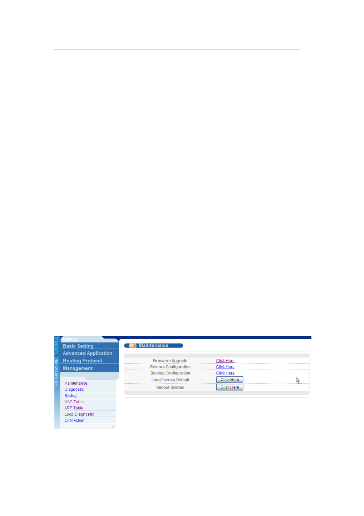
2. Click Management > Maintenance in the navigator panel to display the
following screen.
3. Click the “Click Here” link for Firmware Upgrade to display the following screen.
4. In the File Path field, click Browse to locate the firmware file.
5. Click Upgrade to start the firmware upgrade process.
Using the Console Port:
All contents copyright 2008 ZyXEL Communications Corporation.
3
Page 5
ZyXEL VES-1616/24FA-5x Series Support Notes
1. Download (and unzipped) the correct model firmware to your computer.
2. Connect to the console port and launch a Terminal Emulation software
3. Restart the switch to enter the debug mode via the terminal.
4. Enter “ATUR”.
5. Use the X-modem protocol to transfer (Send File) the firmware.
6. Enter “ATGO” to restart the switch after the file transfer is complete and the
firmware upgrade process is done.
Using FTP:
1. Download (and unzipped) the correct model firmware to your computer.
2. Launch the FTP client on your computer to log into switch. (From the command
prompt, type “ftp <Switch IP>”).
3. Press [ENTER] when prompted for a user name.
4. Enter the administrator login password to access the switch and display FTP
prompt.
5. Enter “bin” to set the transfer mode to binary.
6. Use “put” to transfer the firmware from the computer to the switch, for example:
“put firmware.bin ras-0” transfers the firmware on your computer (firmware.bin)
to the switch and renames it to “ras-0”.
7. Use “put” to transfer the firmware from the computer to the switch, for example:
“put firmware.bin ras-1” transfers the firmware on your computer (firmware.bin)
to the switch and renames it to “ras-1”.
8. Enter “bye” to log out from the switch.
Restore a Configuration File
Using the Web Configurator:
1. Click Management > Maintenance in the navigator panel to display the
following screen.
All contents copyright 2008 ZyXEL Communications Corporation.
4
Page 6
ZyXEL VES-1616/24FA-5x Series Support Notes
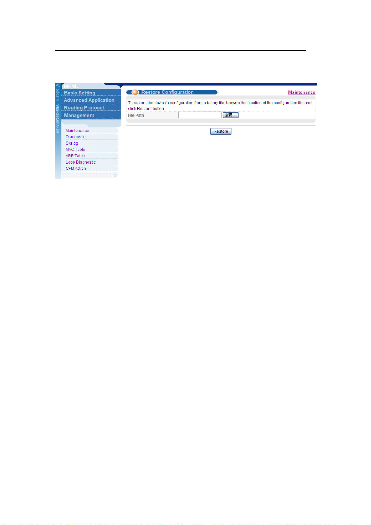
2. Click the “Click Here” link for Restore Configuration to display the following
screen.
3. In the File Path field, click Browse to locate the firmware file.
4. Click Restore to start restoring configuration.
Using the Console Port:
1. Connect to the console port and launch a Terminal Emulation software.
2. Restart the switch to enter the debug mode via the terminal.
3. Enter “ATLC”
4. Use X-modem protocol to transfer (Send File) the configuration file (with a .rom
file extension).
5. Enter “ATGO” to restart the switch after file transfer and the configuration
restore processes are complete.
Using FTP:
1. Download (and unzipped) the correct model firmware to your computer.
2. Launch the FTP client on your computer to log into the switch. (From the
command prompt, type “ftp <Switch IP>”.
3. Press [ENTER] when prompted for a user name
4. Enter the administrator login password to access the switch and display FTP
prompt.
5. Enter “bin” to set the transfer mode to binary.
6. Use “put” to transfer the configuration file from the computer to the switch, for
example: “put comfig.rom config” transfers the configuration file on your
computer (config.rom) to the switch and renames it to “config”.
7. Enter “bye” to log out from the switch.
All contents copyright 2008 ZyXEL Communications Corporation.
5
Page 7
ZyXEL VES-1616/24FA-5x Series Support Notes
Backing Up a Configuration File
Using the Web Configurator:
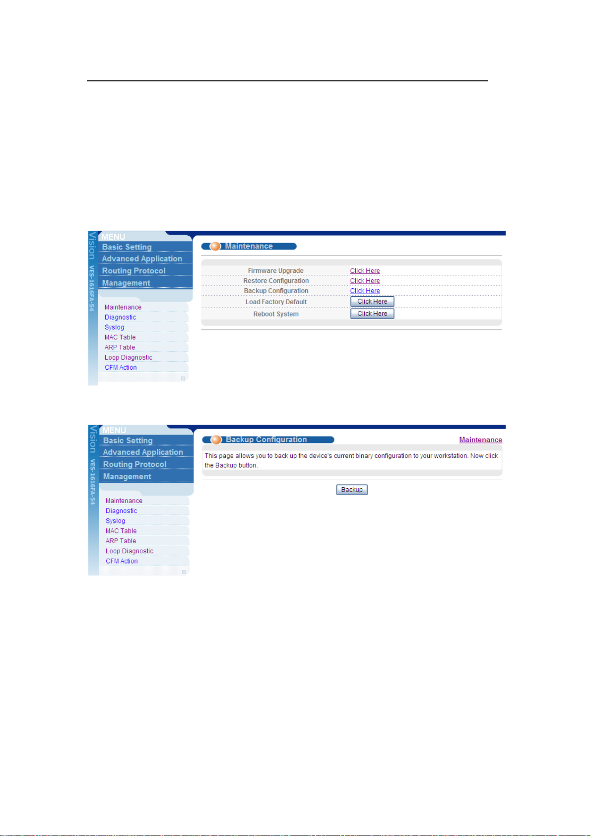
1. Click Management > Maintenance in the navigator panel to display the
following screen.
2. Click the “Click Here” link for Backup Configuration to display the following
screen.
3. Click Backup to display the File Download dialog. Then, click Save to back up
the configuration text file to a location you specify on your computer.
Using the Console Port:
1. Connect to the console port and launch a Terminal Emulation software.
2. Restart the switch to enter the debug mode via the terminal.
3. Enter “ATTD”.
4. Use X-modem protocol to transfer (Receive File) the configuration file (with
a .rom file extension).
All contents copyright 2008 ZyXEL Communications Corporation.
6
Page 8
ZyXEL VES-1616/24FA-5x Series Support Notes
5. Enter “ATGO” to restart the switch after file transfer and the configuration
backup processes are complete. .
Using FTP:
1. Download (and unzipped) the correct model firmware to your computer.
2. Launch the FTP client on your PC to log into the switch. (From the command
prompt, type “ftp <Switch IP>”
3. Press [ENTER] when prompted for a user name
4. Enter the administrator login password to access the switch and display FTP
prompt.
5. Enter “bin” to set the transfer mode to binary.
6. Use “get” to transfer the configuration file from the switch to your computer, for
example: “get config config.rom” transfers the configuration file on the switch
(config) to your computer and renames it “config.rom”.
7. Enter “bye” to log out from the switch.
Load Factory Defaults
Using the Web Configurator:
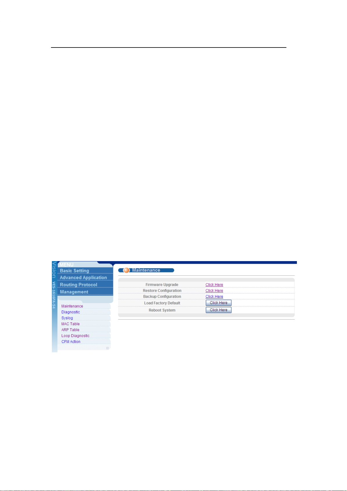
1. Click Management > Maintenance in the navigation panel to display the
following screen.
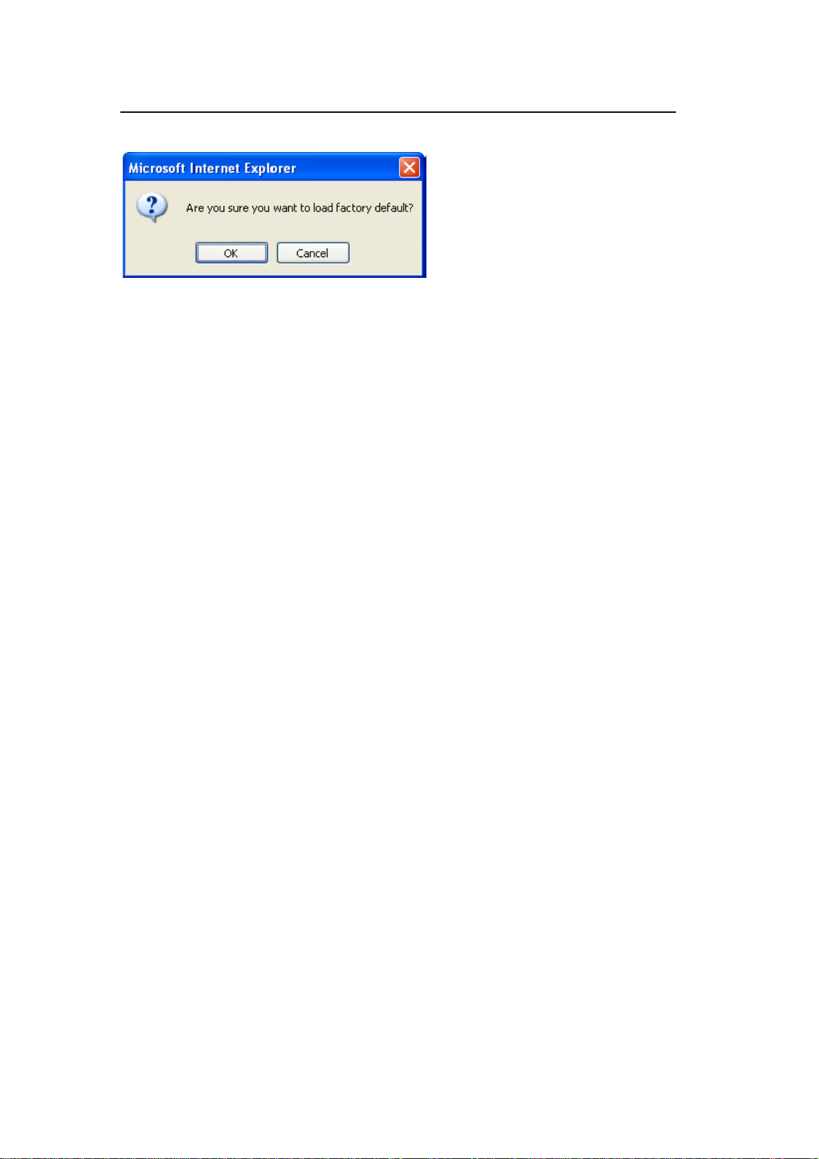
2. Click “Click Here” link for Load Factory Default.
3. A dialog box pops up with the “Are you sure you want to load factory defaults?”
prompt.
All contents copyright 2008 ZyXEL Communications Corporation.
7
Page 9
ZyXEL VES-1616/24FA-5x Series Support Notes
4. Click OK.
5. Click OK again to start the configuration reset process.
6. Please note that the IP address of the switch is now 192.168.1.1.
Using the Console Port:
1. Connect to the console port and open the Terminal Emulation Software.
2. Enter the administrator login password to log into the CLI. Enter “erase run” to
load the factory default configuration.
General Networking
DHCP Relay Option 82 Application
ISP may want to limit the number of IP address or provide some specific client IP
addresses based on the switch ports, VLAN ID and option 82 string.
They can easily achieve this with the DHCP Relay Option 82 feature and a DHCP
server that supports Option 82.
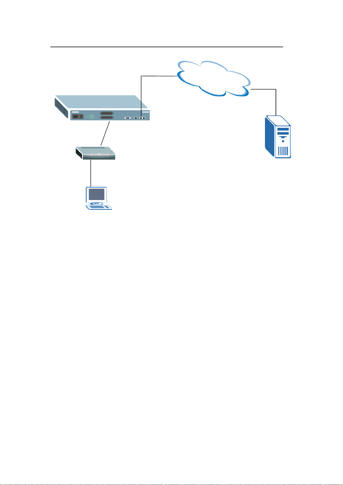
The following figure shows a network example.
All contents copyright 2008 ZyXEL Communications Corporation.
8
Page 10
ZyXEL VES-1616/24FA-5x Series Support Notes
Network
Port 1
DHCP Server
192.168.1.99
DHCP Client
Setting up a DHCP Relay Option 82 Environment
In this example, we will show you how to configure DHCP relay settings to allow a
computer to obtain a specific IP address from a DHCP server based on the VDSL
port, VLAN ID and the Option82 string.
In this network environment, we will use a VES-1616FA-5x series with a computer
connected to a CPE to the first VDSL port. The Option82 string is set to
“VES-1616FA-54”.
The IP address of the DHCP server (IP Commander at 192.168.1.99) and it is to
assign client IP addresses of 192.168.1.201 and 192.168.1.203 for VLAN ID 1
with Option82 string of “VES-1616FA-54”.
1. Switch settings
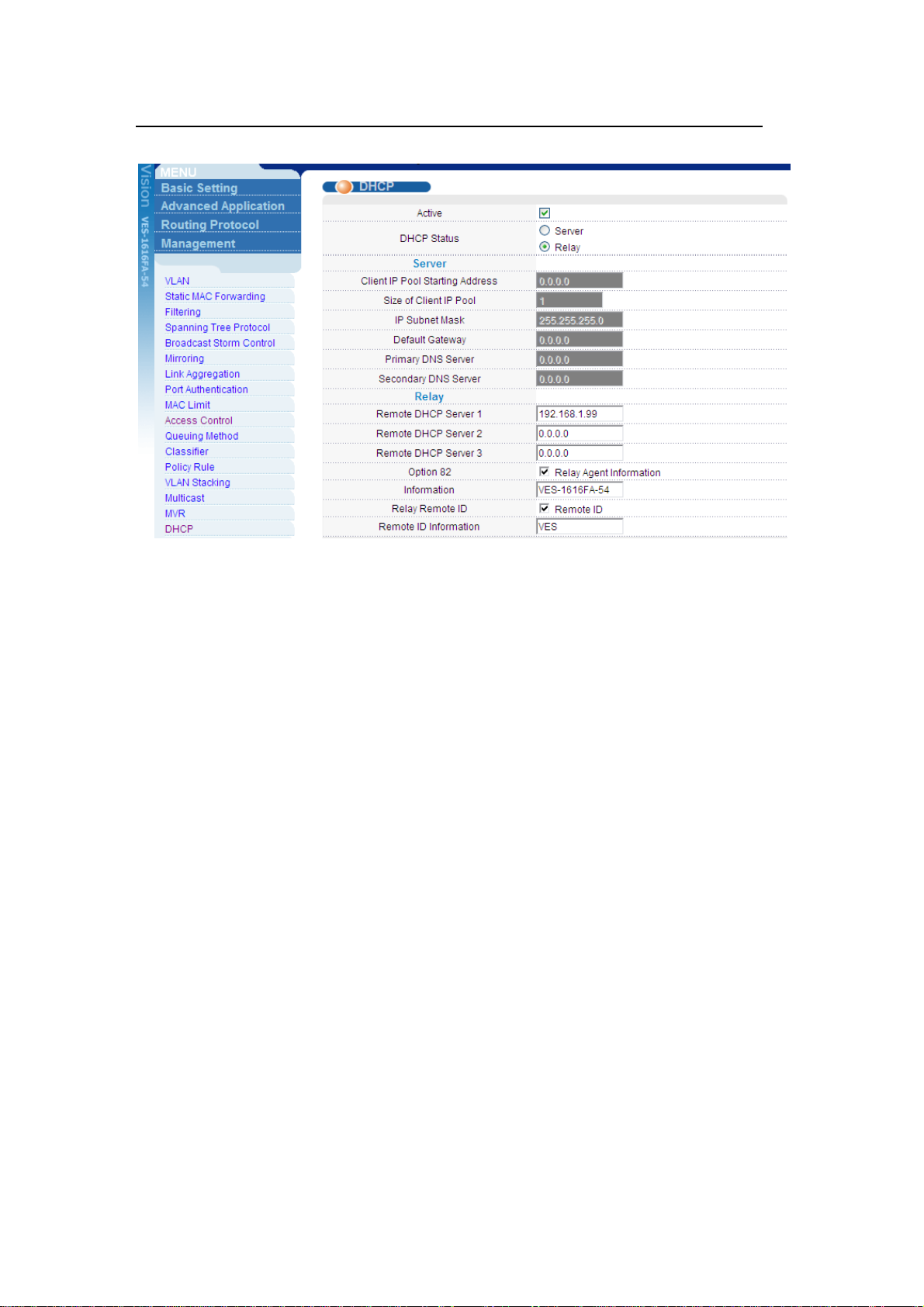
In the web configurator, click Advanced Application > DHCP in the navigation
panel to display the DHCP screen as shown. Enable the DHCP relay feature and
the Option 82 function. Click Information to set “VES-1616FA-54” as the Option
82 string.
All contents copyright 2008 ZyXEL Communications Corporation.
9
Page 11
ZyXEL VES-1616/24FA-5x Series Support Notes
st
Next connect a computer to the Ethernet port of the CPE to the 1
VDSL port.
Refer to the previous application for more information.
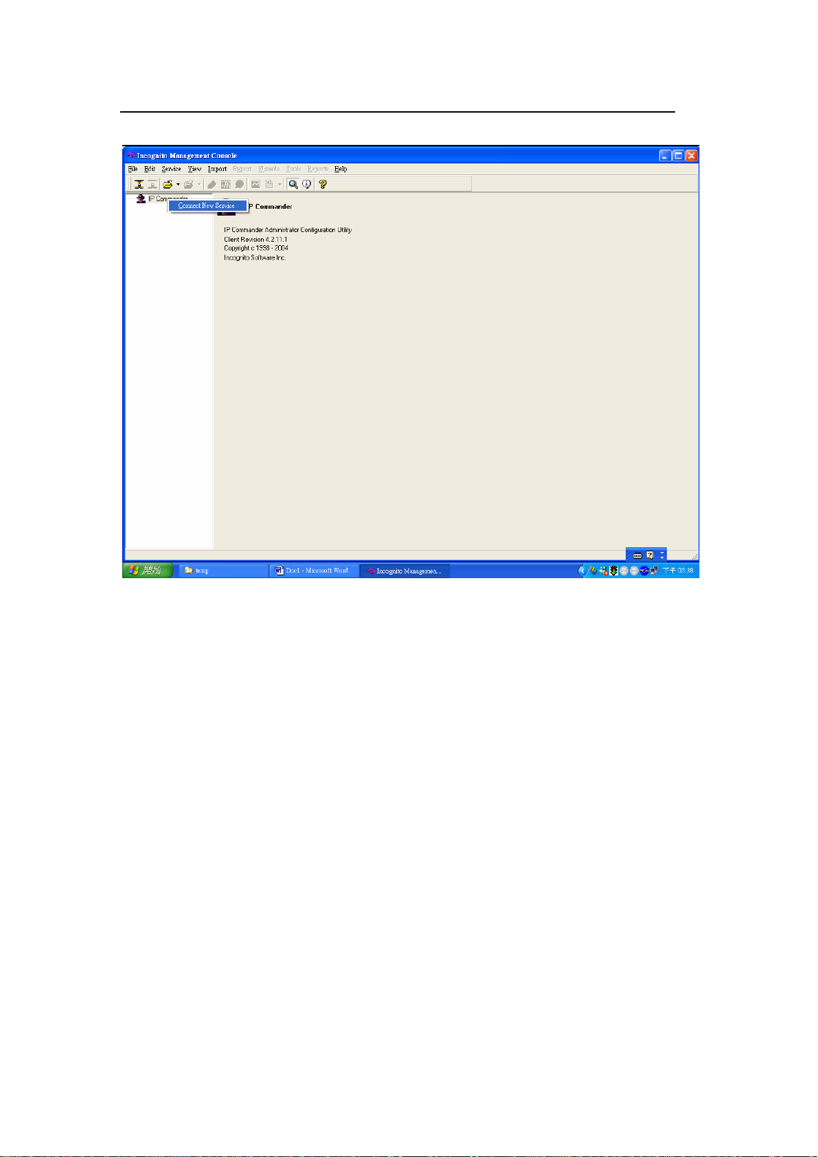
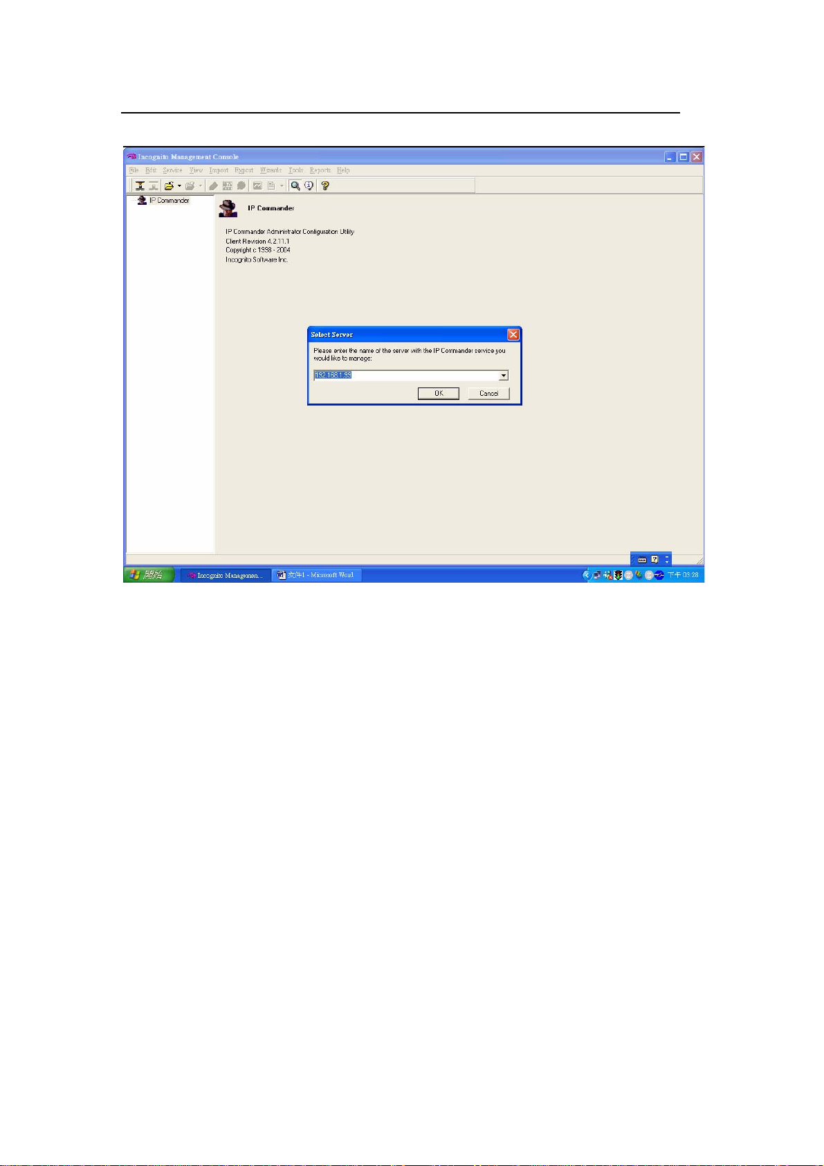
2. IP Commander setup
Launch IP Commander and right-click IP Commander and click Connect New
Server.
All contents copyright 2008 ZyXEL Communications Corporation.
10
Page 12
ZyXEL VES-1616/24FA-5x Series Support Notes
Enter the IP address or domain name for the DHCP server and click OK. For this
example, we enter 192.168.1.99 for the IP address.
All contents copyright 2008 ZyXEL Communications Corporation.
11
Page 13
ZyXEL VES-1616/24FA-5x Series Support Notes
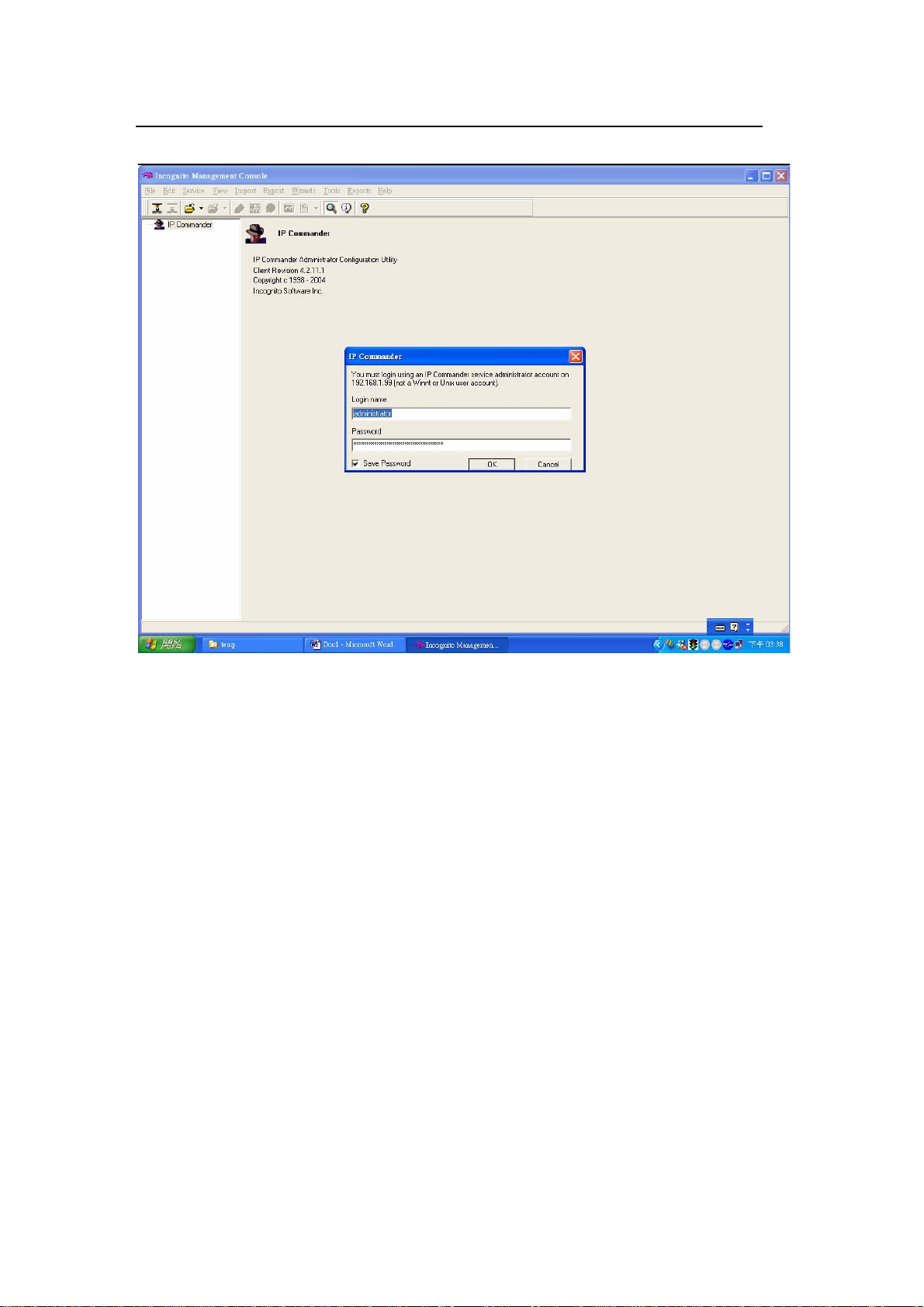
Enter the user name and password. The default user name is “administrator” and
password is “incognito”.
All contents copyright 2008 ZyXEL Communications Corporation.
12
Page 14
ZyXEL VES-1616/24FA-5x Series Support Notes
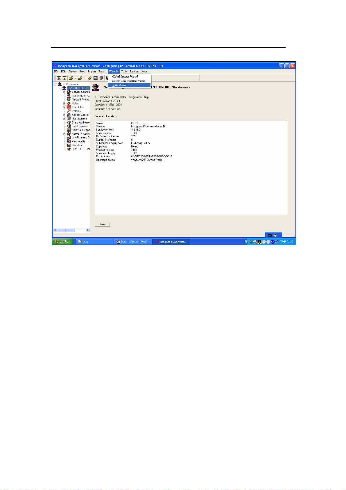
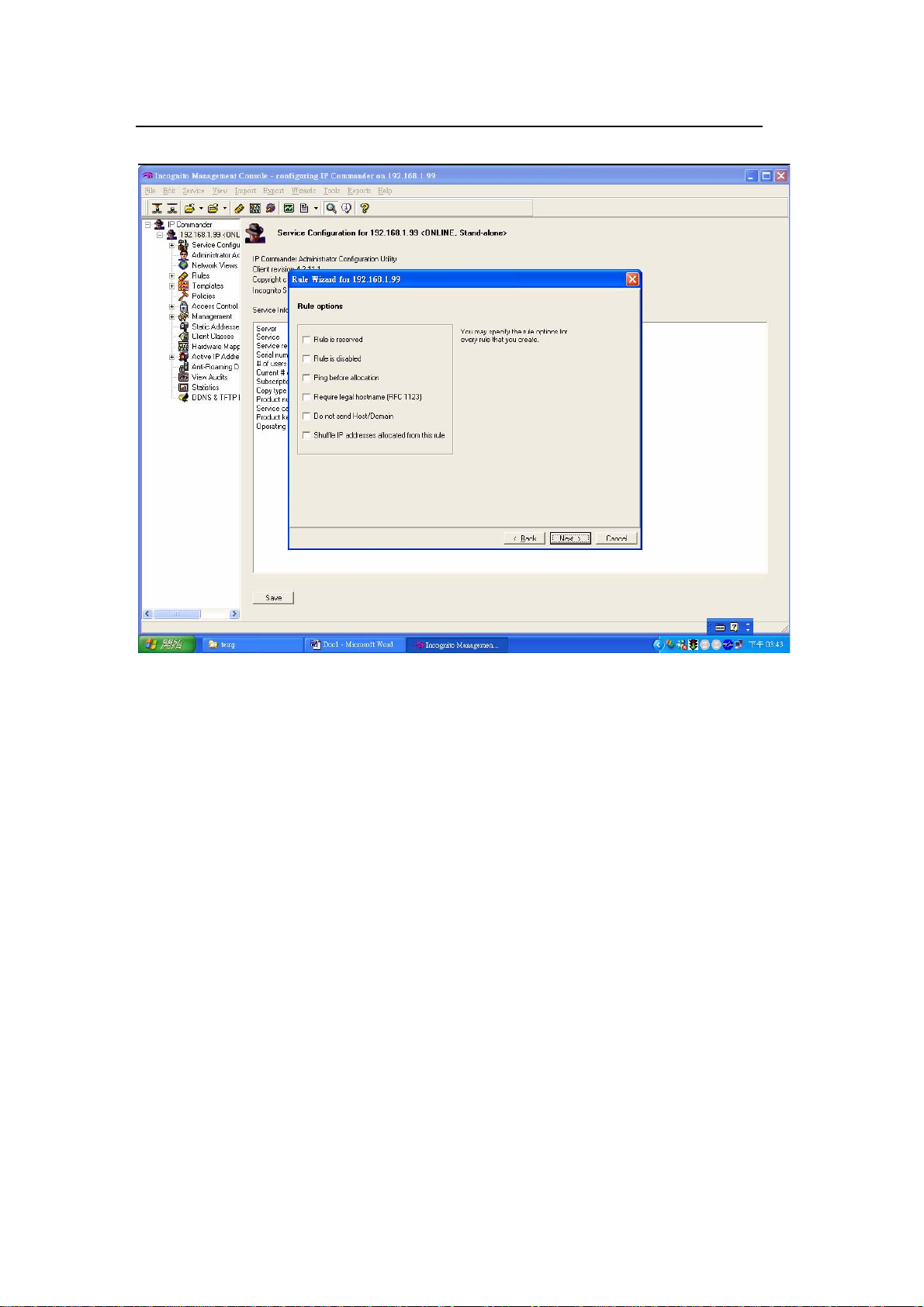
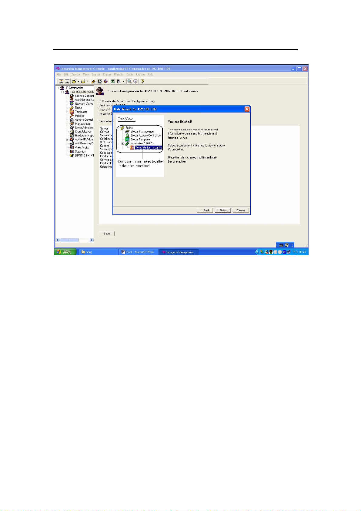
A screen displays. Make sure that the status of your DHCP is online. On the top
menu, click Wizard > Rule Wizard.
All contents copyright 2008 ZyXEL Communications Corporation.
13
Page 15
ZyXEL VES-1616/24FA-5x Series Support Notes
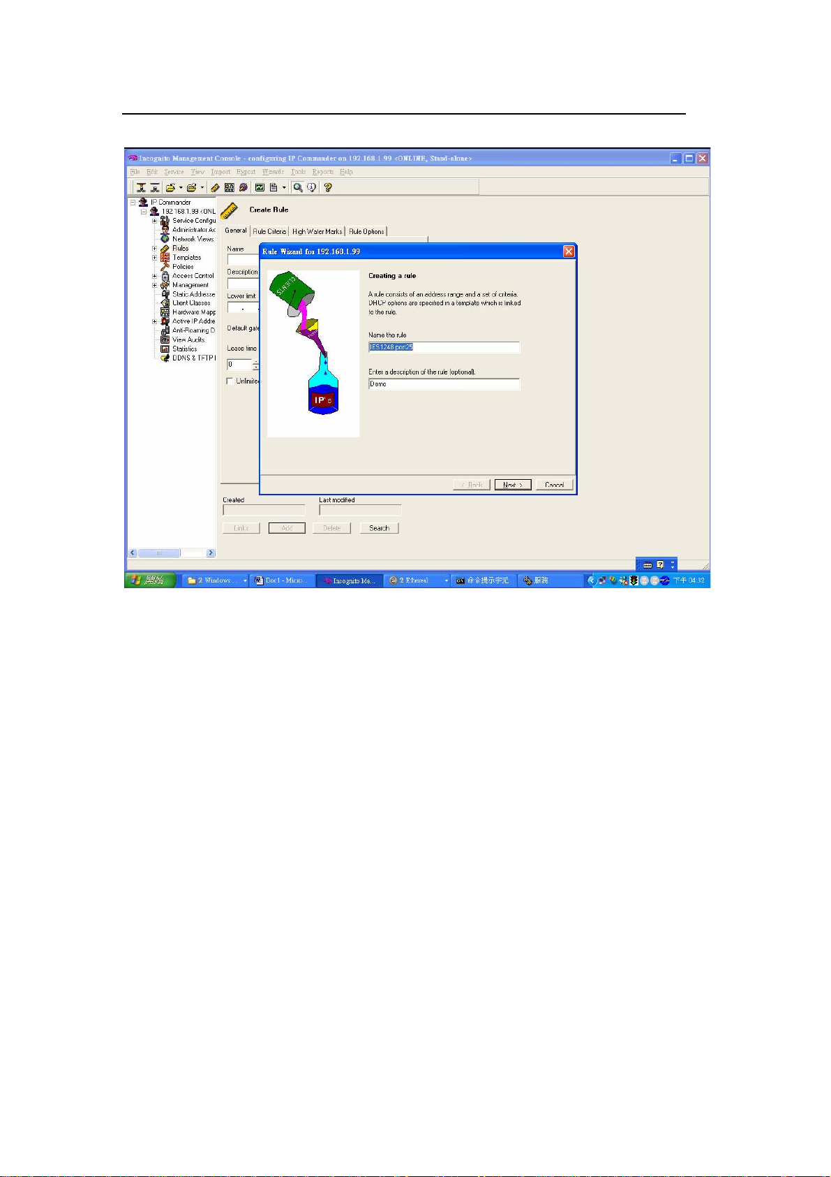
Enter a name and description for the new rule.
All contents copyright 2008 ZyXEL Communications Corporation.
14
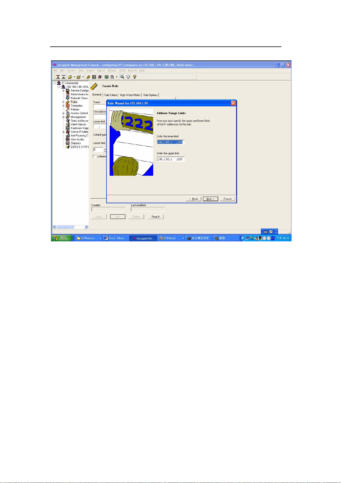
Page 16
ZyXEL VES-1616/24FA-5x Series Support Notes
Specify one or a range of IP addresses for this rule. In this example, we configure
an IP pool from 192.168.1.201 to 192.168.1.203.
All contents copyright 2008 ZyXEL Communications Corporation.
15
Page 17
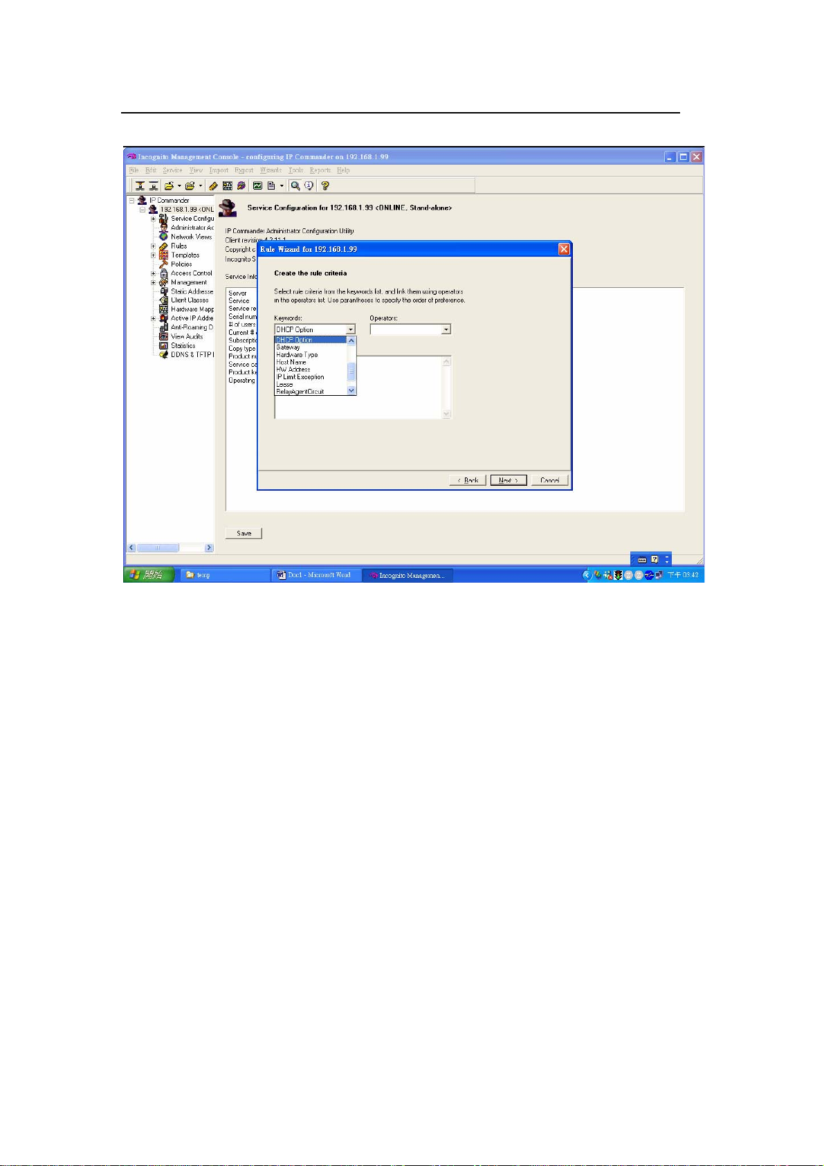
ZyXEL VES-1616/24FA-5x Series Support Notes
Next select DHCP Option in the Keywords field.
All contents copyright 2008 ZyXEL Communications Corporation.
16
Page 18
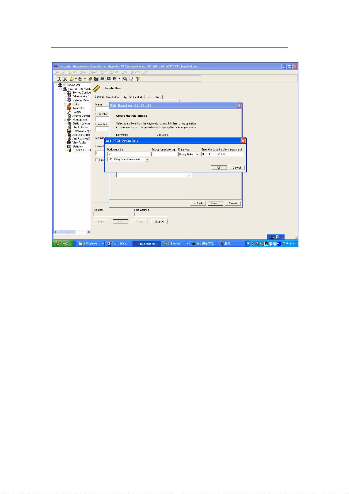
ZyXEL VES-1616/24FA-5x Series Support Notes
An Add DHCP Option Rule screen displays.
Select Option 82 Relay Agent Information, set sub-option 1and use binary data.
For port 1, VLAN 1 with option82 string of “VES-1616FA-54”, enter
“0019000147532d33303132” as the key value and click OK. Note that the first
two bytes define the port number, the second two bytes is the VLAN ID and the
rest of the bytes are the Option 82 string.
All contents copyright 2008 ZyXEL Communications Corporation.
17
Page 19
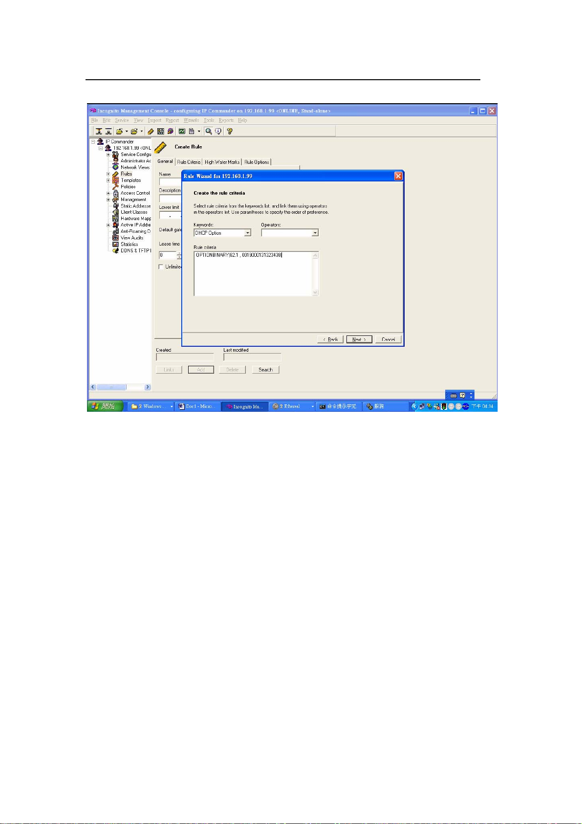
ZyXEL VES-1616/24FA-5x Series Support Notes
After setting the fields, you should see the following screen.
All contents copyright 2008 ZyXEL Communications Corporation.
18
Page 20
ZyXEL VES-1616/24FA-5x Series Support Notes
Click Next in the screen that displays.
All contents copyright 2008 ZyXEL Communications Corporation.
19
Page 21
ZyXEL VES-1616/24FA-5x Series Support Notes
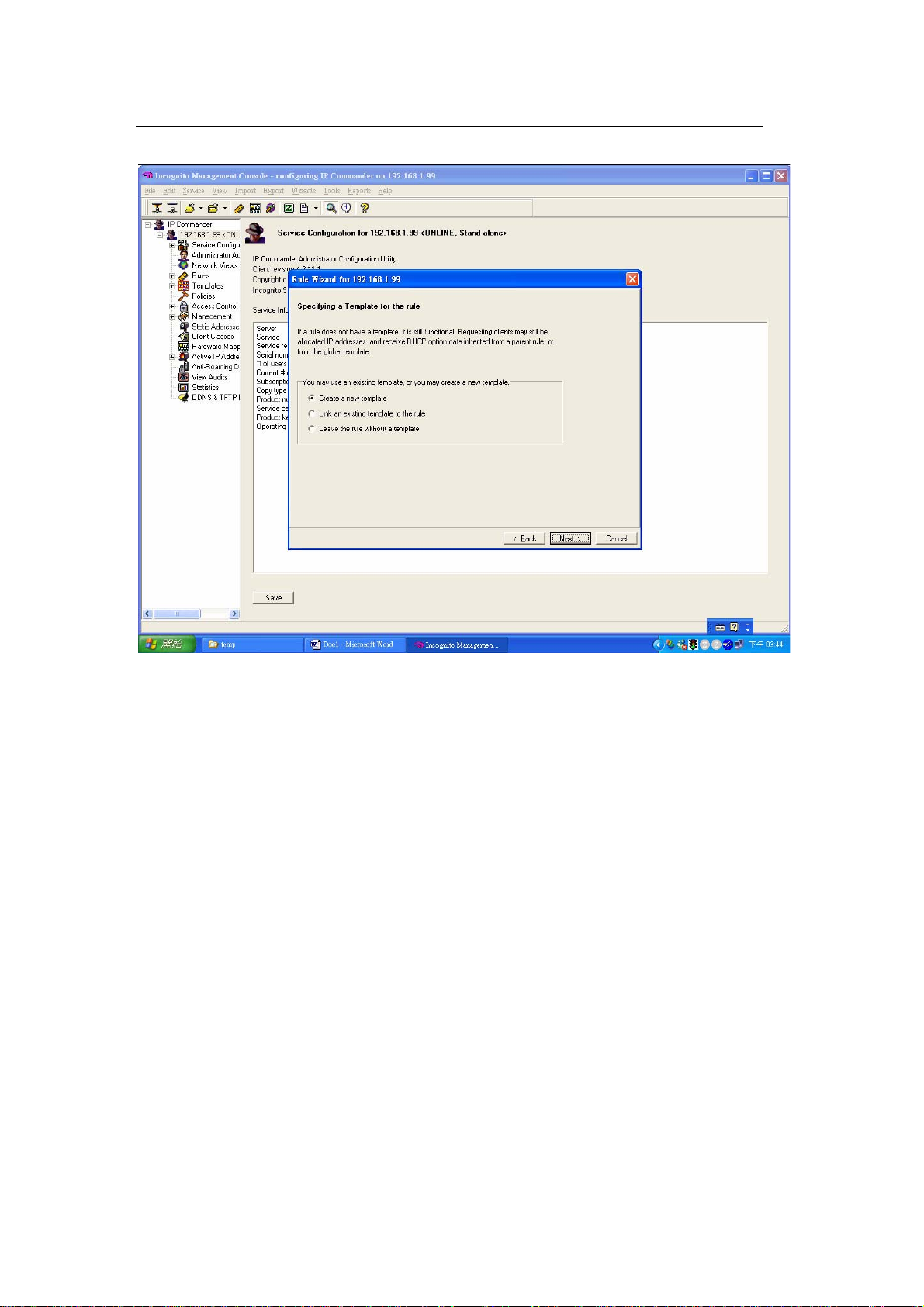
Optionally, you can create a new DHCP template with information such as
gateway, DNS server, etc.
All contents copyright 2008 ZyXEL Communications Corporation.
20
Page 22
ZyXEL VES-1616/24FA-5x Series Support Notes
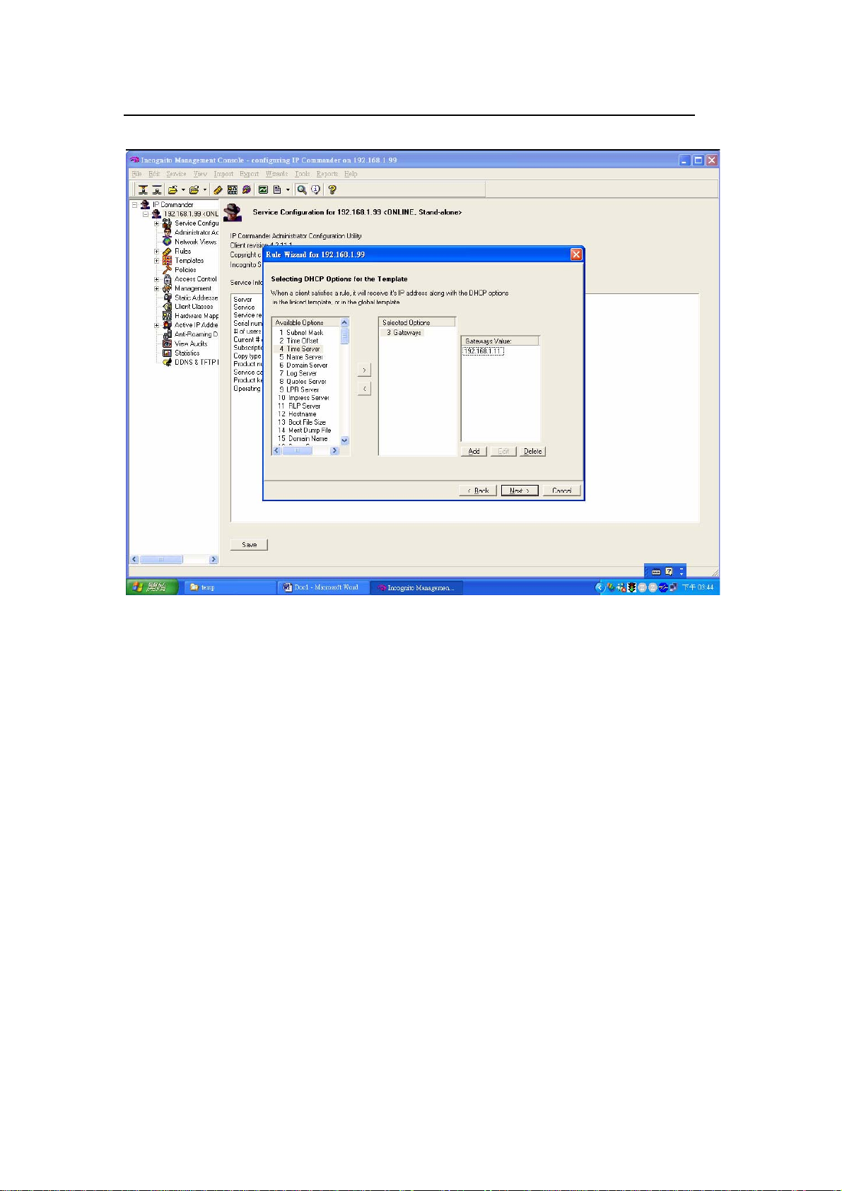
Here, enter “192.168.1.1” as gateway IP address for DHCP clients.
All contents copyright 2008 ZyXEL Communications Corporation.
21
Page 23
ZyXEL VES-1616/24FA-5x Series Support Notes
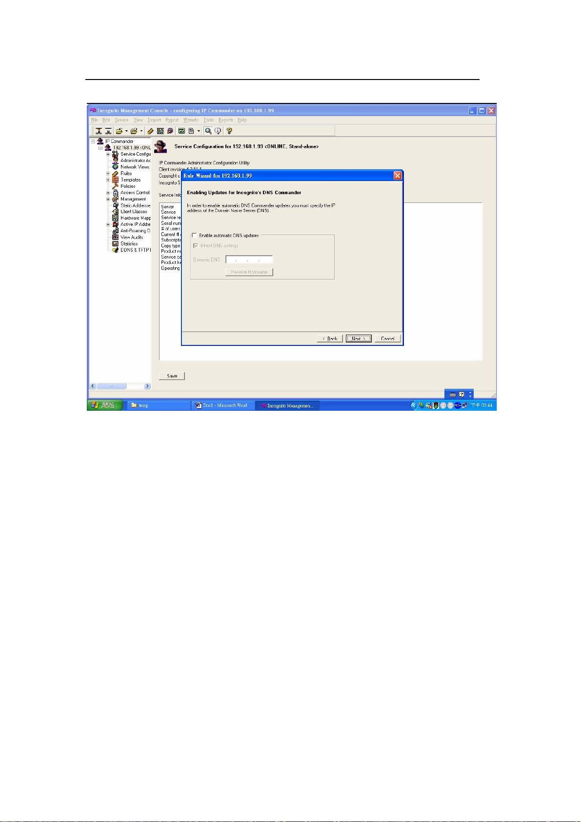
You can choose to enable DDNS service on the DHCP server.
All contents copyright 2008 ZyXEL Communications Corporation.
22
Page 24
ZyXEL VES-1616/24FA-5x Series Support Notes
Click Finish to complete the rule creation.
All contents copyright 2008 ZyXEL Communications Corporation.
23
Page 25
ZyXEL VES-1616/24FA-5x Series Support Notes
After the DHCP server configuration, your computer should be able to get an IP
address of 192.168.1.201 when a DHCP request is sent.
Separating a physical network into multiple
virtual networks
What is Virtual LAN?
VLAN Overview
A VLAN (Virtual Local Area Network) allows a physical network to be partitioned
into multiple logical networks. Stations on a logical network belong to a group
All contents copyright 2008 ZyXEL Communications Corporation.
24
Page 26

ZyXEL VES-1616/24FA-5x Series Support Notes
known as the VLAN Group. A station can belong to more than one group.
Stations in the same VLAN group can communicate with each other. With VLAN,
a station cannot directly communicate with stations that are not in the same VLAN
group(s); the traffic must first go through a router.
In GePON applications, VLAN is vital in providing isolation and security among
subscribers. When properly configured, VLAN prevents one subscriber from
accessing the network resources of another on the same LAN. Thus a user will
not see the printers and hard disks of another user in the same building.
VLAN also increases network performance by limiting broadcasts to a smaller and
more manageable logical broadcast domain. A VLAN group is a broadcast
domain. In traditional Layer-2 switched environments, all broadcast packets go to
each and every individual port. With VLAN, all broadcasts are confined to a
specific broadcast domain.
There are two VLAN implementations: Port-based VLAN and IEEE 802.1q
Tagged VLAN. VES-1616F-3X supports both VLAN implementations. The major
difference between both VLAN implementations is that Tagged VLAN can cross
Layer-2 switches but Port-based VLAN cannot.
Port-based VLAN
Port-based VLANs are VLANs where the packet forwarding decision is based on
the destination MAC address and its associated port. You must define outgoing
ports allowed for each port when using port-based VLANs.
Note that VLAN only
governs the outgoing traffic. In the other word, it is unidirectional.
Therefore, if you wish to allow two subscriber ports to talk to each other, e.g.,
between conference rooms in a hotel, you must define the egress (outgoing port)
for both ports. An egress port is an outgoing port, that is, a port through which a
data packet leaves.
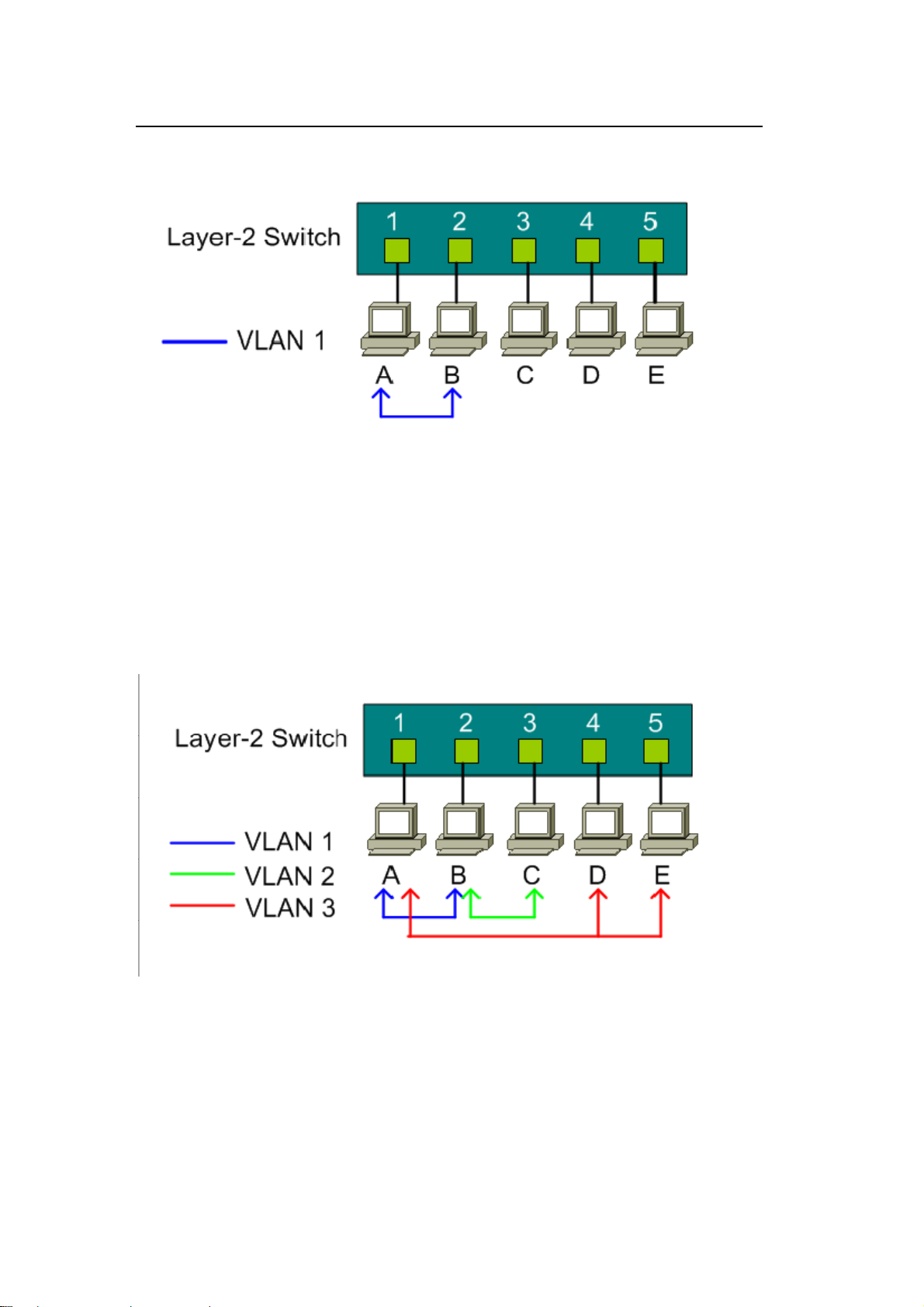
In the following figure, five hosts (A, B, C, D and E) are connected to a 5-port
layer-2 switch which supported port-based VLAN.
Case 1:
Hosts A and B can communicate with each other, because they are in the same
VLAN group. But Hosts A and B cannot communicate with Hosts C, D, and E.
All contents copyright 2008 ZyXEL Communications Corporation.
25
Page 27
ZyXEL VES-1616/24FA-5x Series Support Notes
Port-based VLAN definition:
z Egress port for port 1: port 2
z Egress port for port 2: port 1
Case 2:
In this network example, there are three VLAN groups in the physical network.
Hosts A and B can communicate with each other since they are in the same VLAN
group (VLAN 1). Hosts B and C are in VLAN group 2. Hosts A, D and E are in
VLAN group 3.
Port-based VLAN definition:
z Egress port for port 1: port 2, port 4, port 5
z Egress port for port 2: port 1, port 3
z Egress port for port 3: port 2
z Egress port for port 4: port 1, port 5
z Egress port for port 5: port 1, port 4
All contents copyright 2008 ZyXEL Communications Corporation.
26
Page 28
ZyXEL VES-1616/24FA-5x Series Support Notes
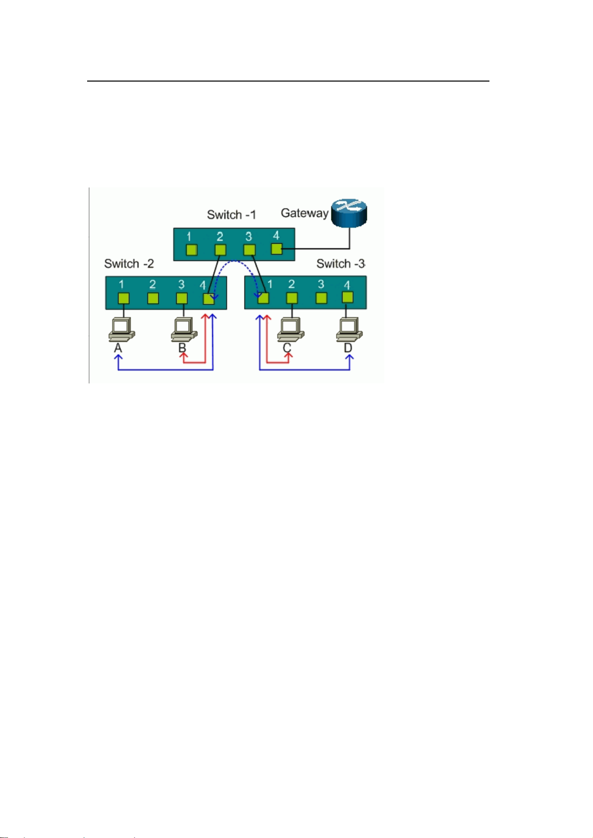
Port-based VLAN across multiple switches
Port-based VLAN is specific only to the switch on which it was created. Thus, port-based
VLAN cannot cross multiple switches. The following figure shows an MTU network
example. For network security, subscribers are isolated from each other except for the
gateway. There are two switches, Switch-2 and Switch-3, that support port-based VLAN
and an uplink to a non-port-based VLAN switch, Switch-1.
For Switch-2, ports 1, 2, and 3 are allowed to communicate with uplink port 4, but not with
other ports.
z Switch-2 VLAN 1 member port: port 1 and port 4
z Switch-2 VLAN 2 member port: port 2 and port 4
z Switch-2 VLAN 3 member port: port 3 and port 4
For Switch-3, ports 2, 3, and 4 are allowed to communicate with uplink port 1, but not with
other ports.
z Switch-3 VLAN 1 member port: port 2 and port 1
z Switch-3 VLAN 2 member port: port 3 and port 1
z Switch-2 VLAN 3 member port: port 4 and port 1
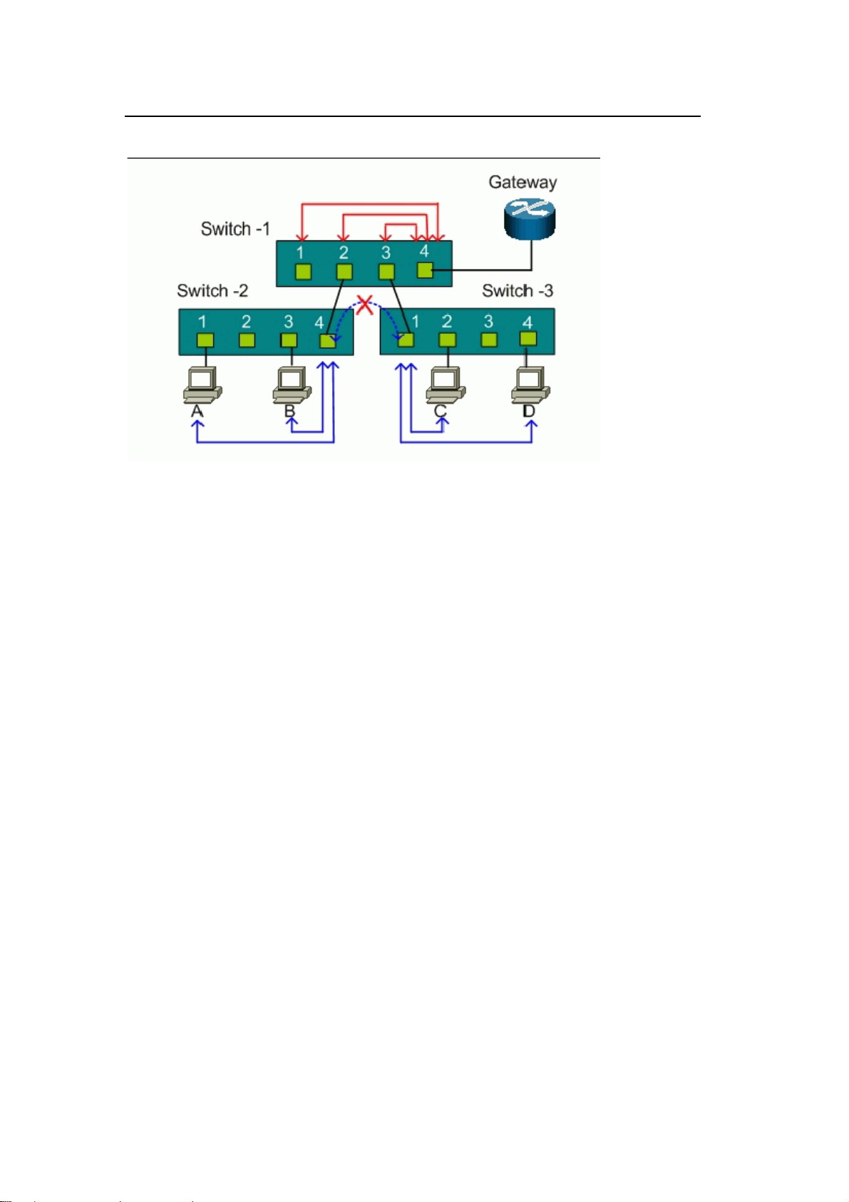
Host A cannot communicate with Host B due to the port-based VLAN implementation on
Switch-2. Host C cannot communicate with Host D due to the port-based VLAN
implementation on Switch-3. However, the uplink ports on both Switch-2 and Switch-3
connect to the non- VLAN Switch-1. Hosts A and B is able to communicate with Hosts C
and D through the non-VLAN switch because port-based VLAN cannot cross multiple
switches.
To provide security between switches, you must install another port-based VLAN switch
for the uplink. Each port on the uplink switch also should be separated into different
VLANs, except for the port connection to the gateway. So subscribers can only connect
to the gateway for Internet access but not communicate with each other.
All contents copyright 2008 ZyXEL Communications Corporation.
27
Page 29
ZyXEL VES-1616/24FA-5x Series Support Notes
For Switch-1, ports 1, 2, and 3 are allowed to communicate with uplink port 4, but not with
other ports.
z Switch-1 VLAN 1 member port: port 1 and port 4
z Switch-1 VLAN 2 member port: port 2 and port 4
z Switch-1 VLAN 3 member port: port 3 and port 4
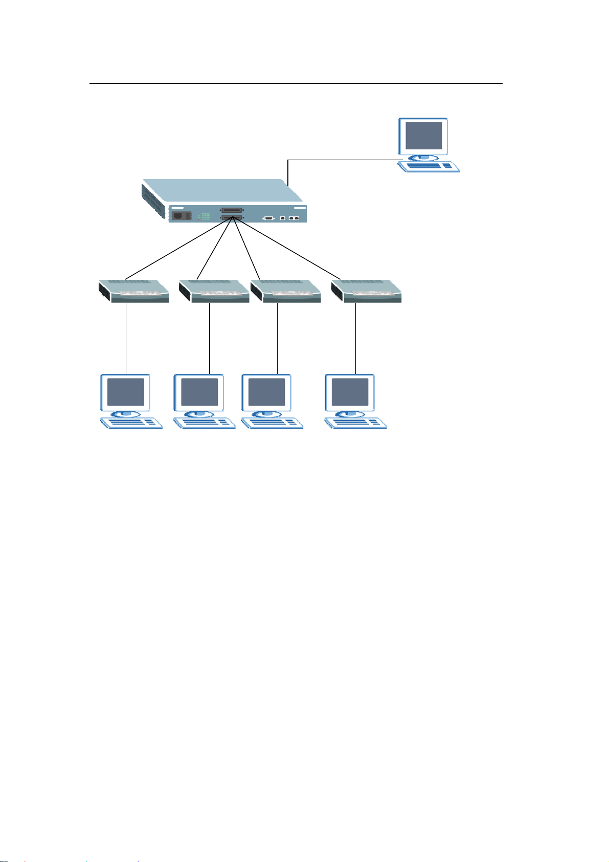
How to configure Port-Based VLAN
Port-based VLANs are VLANs where the packet forwarding decision is based on
the destination MAC address and its associated port.
All contents copyright 2008 ZyXEL Communications Corporation.
28
Page 30
ZyXEL VES-1616/24FA-5x Series Support Notes
PC Z
Port 1 ~ 4
PC A
In this scenario, Port Based VLAN is used to separate one physical switch into
two smaller logical switches. Ports 1~4 and 17, 18 belong to the same VLAN
group, and ports 5~8 are in another group. Port-based VLANs are specific only to
the switch on which they were created.
PC B PC C PC D
Port 5 ~ 8
Configuring the Switch Using the Web Configurator
1. Use an RJ-45 Ethernet cable to connect a computer to the management port
on the switch.
2. By default the management IP address of the switch is 192.168.0.1/24
3. Set the IP settings on your computer to 192.168.0.2/24
4. Open a web browser such as IE and enter http://192.168.0.1 as the URL.
5. When prompted, enter “admin” as the username and “1234” as the password.
6. After you have logged in successfully, the main web configurator screen
displays.
All contents copyright 2008 ZyXEL Communications Corporation.
29
Page 31

ZyXEL VES-1616/24FA-5x Series Support Notes
7. First, set the switch to use port based VLAN. Click Basic Setting > Switch
Setup in the navigation panel and select “Port Based” in the VLAN Type field.
Click Apply to save your changes.
8. Next create logical partitions on the switch. Click Advanced Application >
VLAN in the navigation panel and select the ports to belong to the VLAN. For this
example, select ports 1~4 and 17, 18 to belong to a VLAN so they can
communicate with each other.
Although ports 5~8 are in another group, both groups cannot communicate with
each other. Here we also defined ports 17 and 18 as the uplink ports. Therefore,
All contents copyright 2008 ZyXEL Communications Corporation.
30
Page 32

ZyXEL VES-1616/24FA-5x Series Support Notes
both groups can pass data to ports 17 and 18. In another word, these two ports
belong to both VLAN groups at the same time. The configuration screen should
look similar to the screen as shown.
9. Finally, verify the settings. If you have configured the VLAN settings properly,
PC A can ping PC B and PC Z but not PC C or PC D and vice versa.
10. For example,
PC A: 192.168.1.4/24
PC B: 192.168.1.5/24
PC C: 192.168.1.6/24
PC D: 192.168.1.7/24
PC Z: 192.168.1.99/24
11. PING PC B from PC A (successful reply messages)
12. PING PC Z from PC A (successful reply messages)
All contents copyright 2008 ZyXEL Communications Corporation.
31
Page 33

ZyXEL VES-1616/24FA-5x Series Support Notes
13. PING PC C from PC A (not successful with request timed out message)
Configuring the Switch Using the CLI
1. Connect the your computer to the console port on the switch
2. Open your Terminal program (for example, Hyper Terminal in Windows
System).
3. Make sure the console connection settings are configured as listed below.
Bps: 9600
Data bits: 8
Parity: None
Stop bits: 1
Flow control: None:
4. After you can connect successfully, enter the user name and password.
5. Enter “config” to go into the configuration mode.
6. Enter the following commands to configure Port Based VLAN on your Switch in
this network example.
All contents copyright 2008 ZyXEL Communications Corporation.
32
Page 34

ZyXEL VES-1616/24FA-5x Series Support Notes
7. After entering the commands, use the “write memory” command under the
enable mode to save your configuration.
What is IEEE 802.1Q Tag-based VLAN?
Tag-based VLAN Overview
In the IEEE 802.1Q standard, Tag-based VLAN uses an extra tag in the MAC
header to identify the VLAN membership of a frame across bridges. This tag is
used for VLAN and QoS (Quality of Service) priority identification. The VLANs can
be created statically by an administrator or dynamically through GVRP. The
VLAN ID associates a frame with a specific VLAN and provides the information
that switches need to process the frame across the network. A tagged frame is
four bytes longer than an untagged frame and contains two bytes of TPID (Tag
Protocol Identifier, residing within the type/length field of the Ethernet frame) and
two bytes of TCI (Tag Control Information, starts after the source address field of
the Ethernet frame).
All contents copyright 2008 ZyXEL Communications Corporation.
33
Page 35

ZyXEL VES-1616/24FA-5x Series Support Notes
z TPID: TPID has a defined value of 8100 in hex. When a frame has the
EtherType equal to 8100, this frame carries the IEEE 802.1Q / 802.1P tag.
z Priority: The first three bits of the TCI define user priority, giving eight (2^3)
priority levels. IEEE 802.1P defines the operation for these 3 user priority bits.
z CFI: Canonical Format Indicator is a single-bit flag, always set to zero for
Ethernet switches. CFI is used for compatibility reason between Ethernet type
network and Token Ring type network. If a frame received at an Ethernet port
has a CFI set to 1, then that frame should not be forwarded as it is to an
untagged port.
z VID: VLAN ID is the identification of the VLAN, which is used by the standard
802.1Q. It is 12 bits long and allows the identification of 4096 (2^12) VLANs. Of
the 4096 possible VIDs, a VID of 0 is used to identify priority frames and value
4095 (FFF) is reserved, so the maximum possible VLAN configurations are
4,094.
z Note that user priority and VLAN ID are independent of each other. A
frame with VID (VLAN Identifier) of null (0) is called a priority frame,
meaning that only the priority level is significant and the default VID of
the ingress port is given as the VID of the frame.
How 802.1Q VLAN works
Based on the VID information in the tag, the switch forwards and filters frames on
the ports. Ports with the same VID can communicate with each other. IEEE
802.1Q VLAN function defines three tasks: Ingress Process, Forwarding Process
and Egress Process.
All contents copyright 2008 ZyXEL Communications Corporation.
34
Page 36

ZyXEL VES-1616/24FA-5x Series Support Notes
1. Ingress Process:
Each port is capable of passing tagged or untagged frames. Ingress Process
identifies if the incoming frames contain a tag, and classifies the incoming frames
belonging to a VLAN. Each port has its own Ingress rule. If an Ingress rule
accepts tagged frames only, the switch will drop all incoming non-tagged frames
on the port. If an Ingress rule accepts all frame types, the switch allow both
incoming tagged and untagged frames on the port.
When a tagged frame is received on a port, it carries a tag header that has an
explicit VID. Ingress Process directly passes the tagged frame to Forwarding
Process.
An untagged frame does not carry any VID to which it belongs. When an
untagged frame is received, Ingress Process inserts a tag contained the PVID into
the untagged frame. Each physical port has a default VID called PVID (Port VID).
PVID is assigned to untagged frames or priority tagged frames (frames with null (0)
VID) received on this port.
After Ingress Process, all frames have a 4-bytes tag and VID information, and
they are transitioned into Forwarding Process.
2. Forwarding Process:
The Forwarding Process makes forwarding decisions on the received frames
All contents copyright 2008 ZyXEL Communications Corporation.
35
Page 37

ZyXEL VES-1616/24FA-5x Series Support Notes
based on the Filtering Database. If you want to allow tagged frames to be
forwarded to a certain port, this port must be the egress port of this VID. The
egress port is an outgoing port for the specified VLAN, that is, frames with a
specified VID tag can go through this port. Filtering Database stores and
organizes VLAN registration information useful for switching frames to and from
switch ports. It consists of static registration entries (Static VLAN or SVLAN table)
and dynamic registration entries (Dynamic VLAN or DVLAN table). SVLAN table
is manually added and maintained by the administrator.
DVLAN table is automatically learned via GVRP protocol, and can't be created or
updated by the administrator.
VLAN entries in Filtering Database have the following information:
1. VID: VLAN ID
2. Port: The switch port number
3. Ad Control: Registration administration control. There are 3 types of ad control,
including forbidden registration, fixed registration and normal registration.
z Forbidden registration: This port is forbidden to be the egress port of the
specified VID.
z Fixed registration: While ad control is fixed registration, it means this is a
static registration entry. This port is the egress port of the specified VID
(a member port of the specified VLAN). Frames with the specified VID
tag can go through this port.
z Normal registration: While ad control is normal registration, it means this
is a dynamic registration entry. The forwarding decision is depended on
the Dynamic VLAN table.
4. Egress tag Control: This information is used for Egress Process. The value
may be tagged or untagged. If the value is tagged, outgoing frames on the egress
port is tagged. If the value is untagged, the tag will be removed before a frame
leaves the egress port.
All contents copyright 2008 ZyXEL Communications Corporation.
36
Page 38

ZyXEL VES-1616/24FA-5x Series Support Notes
3. Egress Process:
The Egress Process decides if the outgoing frames are to be sent tagged or
untagged. The Egress Process refers to the egress tag control information in
Filtering Database. If the value is tagged, outgoing frames on the egress port is
tagged. If the value is untagged, the tag will be removed before a frame leaves the
egress port.
Connecting Two Switches using VLAN
This example shows you how to configure VLAN settings on two VES-1616FA-54
switches which are connected using the Ethernet port. There are five VLANs on
the first switch and seven VLANs on the second switch. The Ethernet port is port
17 on both switches. VLANs are configured on the switches but how to configure
port 17 as the trunk port on both switches?
The following figure shows this network example.
All contents copyright 2008 ZyXEL Communications Corporation.
37
Page 39

Z
yX
eVLAVLA
V
V
Al
0
0
f
f
o
n
0
0
o
o
8
w
0
n
A
B
VE
m
e
F
n
o
A
s
o
N
EL
S-1616/24
A-5x Serie
Support
otes
Th
VLAN co
1.
LAN Con
N 101, 1
N 101, 1
nfiguratio
2, 103, 1
2, 103, 1
iguration
s on the t
4, 105, 1
4, 105, o
n switch
o switch
6, 107 on
switch B
s are as f
switch
llows:
2.
LAN Con
iguration
l contents c
n switch
pyright 200
ZyXEL Co
municatio
s Corporati
n.
38
Page 40

ZyXEL VES-1616/24FA-5x Series Support Notes
Answer:
------------------------------------In switch A, add port 17 in each VLAN
VID:101 (port 1,2,"17 TAG")
VID:102 (port 3,4,"17 TAG")
VID:103 (port 5,6,"17 TAG")
VID:104 (port 7,8,"17 TAG")
VID:105 (port 9,10,"17 TAG")
VID:106 (port 11,12,13,"17 TAG")
VID:107 (port 14,15,16,"17 TAG")
------------------------------------In switch B, add port 17 in each VLAN
VID:101 (port 1,2,3,"17 TAG")
VID:102 (port 4,5,6,"17 TAG")
VID:103 (port 7,8,9,"17 TAG")
VID:104 (port 10,11,12,"17 TAG")
VID:105 (port 13,14,15,16,"17 TAG")
Clients in the same VLAN on both switches can communicate with each other.
PVID:
Set PVID on switch A
Port 1, 2 : 101
Port 3, 4 : 102
Port 5, 6 : 103
Port 7, 8 : 104
Port 9, 10 : 105
Port 11, 12, 13 : 106
Port 14, 15, 16 : 107
port 25: PVID=any
Set PVID on switch B:
All contents copyright 2008 ZyXEL Communications Corporation.
39
Page 41

Z
yX
rPorPorPorPorPor
t
o
m
AThe
e
Al
1
1
1
=
L
e
r
n
n
n
a
o
5
o
o
i
o
8
N
a
a
S
t
c
VE
m
N
P
r
7
m
w
F
n
c
e
E
A
o
s
o
w
w
n
n
N
s
f
o
EL
Po
t 1, 2, 3 :
t 4, 5, 6 :
t 7, 8, 9 :
t 10, 11, 1
t 13, 14, 1
t 25:PVID
01
02
03
2 : 104
5, 16 : 10
any
S-1616/24
A-5x Serie
Support
otes
ting up V
Se
Wit
h the ben
thr
ugh a po
fro
PC1 co
the
VLAN tru
N Trunki
VL
following
AN Trunki
fit of depl
t that is c
nected to
king port.
g port wh
figure sh
ng
ying VLA
nfigured
switch 1 c
In this ex
le on VE
ws the ne
trunking
s the VLA
an reach
mple, po
2, port 1
work exa
, you can
trunking
C 2 conn
t 17 on V
is the VL
ple.
onnect t
port. VLA
cted to s
S 1 is co
N Trunki
o switche
N tagged
itch 2 thr
figured as
g port.
rames
ugh
the
Th
configur
tion scree
l contents c
n for swit
pyright 200
h 1 is sho
ZyXEL Co
n as foll
municatio
ws.
s Corporati
n.
40
Page 42

ZyXEL VES-1616/24FA-5x Series Support Notes
The configuration screen for switch 2 is shown as follows.
All contents copyright 2008 ZyXEL Communications Corporation.
41
Page 43

ZyXEL VES-1616/24FA-5x Series Support Notes
In the VES 1, we set port 1 as VLAN 2 untag
In the VES 2, we set port 2 as VLAN 2 untag.
The switch 1 IP address: 192.168.1.31
The switch 2 IP address: 192.168.1.21
After the configuration, you can see that PC 1 connected to port 2 on switch 1 can
still ping PC 2 connected to port 6 on switch 2.
All contents copyright 2008 ZyXEL Communications Corporation.
42
Page 44

ZyXEL VES-1616/24FA-5x Series Support Notes
All contents copyright 2008 ZyXEL Communications Corporation.
43
Page 45

ZyXEL VES-1616/24FA-5x Series Support Notes
V
V
V
V
V
V
V
V
y
y
VLAN Stacking Overview
VLAN stacking allows a carrier to offer multiple virtual LANs over a single circuit.
In essence, the carrier creates an Ethernet VPN to tunnel customer VLANs
across its WAN. Thus it helps to avoid name conflicts among customers of
multiple service providers who connect to the same carrier.
VLAN stacking works by assigning two VLAN IDs to each frame header. One is a
"backbone" VLAN ID used by the service provider, the other (up to 4,096 unique
802.1Q VLAN tags) is used by the customers.
The following figure shows a network example.
Company XX branch
Compan
YY branch
Switch
H
LAN 2
Port 17
Switch
A
Port
2
Port 17
Company XX HQ
LAN 30|VLAN 2
Switch
B
Port
1
LAN 2
Port
25
Port
25
LAN 40|VLAN 2
LAN 30|VLAN 2
Switch
C
Port
26
Port
LAN 40|VLAN 2
27
Port 25
Switch G
Port
1
Compan
Port 25
LAN 2
Switch
E
Port 17
Switch
D
Port 17
YY HQ
LAN 2
Port
1
Switch
F
In this example, company XX and company YY both subscribe to the same ISP
for Internet service. Both companies have an internal VLAN group with VID 1. In
order to prevent VLAN-tagged packets between these two companies from
transmitting to each other’s network, VLAN stacking is implemented in the ISP’s
network. The ISP assigns a service provider VID for each company- company XX
is assigned an SP VID of 30 and company YY is assigned an SP VID of 40.
The following shows the packet flow between Company XX HQ and its branch
All contents copyright 2008 ZyXEL Communications Corporation.
44
Page 46

ZyXEL VES-1616/24FA-5x Series Support Notes
office.
Company XX HQ Æ Switch A Æ Switch B Æ Switch C Æ Switch D Æ Company
XX Branch Office.
In this case, VLAN Stacking is enabled on access ports 11 and 12 on Switch B.
An SP tag is appended for ingress traffic and the appended SP tagged is removed
during egress. VLAN Stacking is also enabled on the tunnel port on switches B
(port 10), C, and D. Static VLAN Tx tagging must be DISABLED for the port which
is set as a Normal or Access Port. Static VLAN Tx Tagging MUST be enabled on
a port set as the Tunnel port.
The following shows the packet flow between Company YY HQ and its branch
office.
Company YY HQ Æ Switch F Æ Switch G Æ Switch C Æ Switch B Æ Switch H
Æ Company YY Branch Office.
VLAN Stacking is enabled on access port 10 on Switch G. An SP tag is appended
on the ingress traffic and the SP tag is removed during egress. VLAN Stacking is
enabled on a Tunnel port on switches G (port 9), C, and B.
From Switch A to Switch H
Switch A:
Enabled VLAN, VLAN1 and egress tagging on Port 17
Port 1 is connected to another access switch in a building.
Port 17 is connected to port 11 on Switch B
Switch B:
Enabled VLAN Stacking and STP
Port 1 is connected to port 17 on Switch A
Port 2 is connected to port 17 on Switch H
Port 25 is connected to port 25 Switch C
Switch C:
Enabled VLAN Stacking and STP
Port 27 is connected to port 25 on Switch G
Port 26 is connected to port 25 on Switch D
Port 25 is connected to port 25 on Switch B
Switch D:
Enabled VLAN Stacking
Port 1 is connected to port 17 on Switch E
Port 25 is connected to port 26 on Switch C
Switch E:
Enabled VLAN, VLAN1, and egress tagging on Port 17
Port 1 is connected to another access switch in the building.
Port 17 is connected to port 1 on Switch D
Switch F:
Enabled VLAN, VLAN1, and egress tagging on Port 17
Port 1 is connected to another access switch in the building.
Port 17 is connected to port 1 on Switch G
Switch G:
All contents copyright 2008 ZyXEL Communications Corporation.
45
Page 47

ZyXEL VES-1616/24FA-5x Series Support Notes
Enabled VLAN Stacking
Port 1 is connected to port 17 on Switch F
Port 25 is connected to port 27 on Switch C
Switch H:
Enabled VLAN, VLAN1, and egress tagging on Port 17
Port 1 is connected to another access switch in the building.
Port 17 is connected to port 2 on Switch B
Configuring Switch A, E, F and H Using the Web Configurator
On switches A, E, F and H, create a VLAN (with VID 1) which contains all the port
members. By default VLAN1 is already created for you. The setting required is to
make sure that port 17 is a member of VLAN 1 and that egress tagging is enabled
on the port.
*By default all the ports in VLAN 1 are untagged during Egress.
Configuring Switch B Using the Web Configurator
1. Use an RJ-45 Ethernet cable to connect your computer to the MGMT port on
the switch.
2. By default, the IP address on the MGMT port is 192.168.0.1/24
3. Set your computer to use a static IP address in the same subnet (for example,
192.168.0.2/24).
4. Open a web browser (such as IE) and enter http://192.168.0.1 as the URL.
5. A login screen displays. Enter “admin” (the default) as the username and “1234”
(the default) as the password.
6. After you have logged in successfully, the main screen displays as shown.
All contents copyright 2008 ZyXEL Communications Corporation.
46
Page 48

ZyXEL VES-1616/24FA-5x Series Support Notes
7. First, create VLAN groups for the ISP’s network. For this example, VLAN 30 for
company XX and VLAN 40 for company YY. Click Advanced Application>
Switch Advance> VLAN and click the Static VLAN link.
All contents copyright 2008 ZyXEL Communications Corporation.
47
Page 49

ZyXEL VES-1616/24FA-5x Series Support Notes
8. Create a VLAN with a VID of 30. Select Fixed and un-select Tx Tagging for
port 1. For port 25, select both Fixed and Tx Tagging.
9. Create another VLAN with a VID of 40. Select Fixed and un-select Tx Tagging
for port 2.
10. For port 12, select both Fixed and Tx Tagging. The VLAN Status screen
should display as shown.
All contents copyright 2008 ZyXEL Communications Corporation.
48
Page 50

ZyXEL VES-1616/24FA-5x Series Support Notes
11. To configure VLAN Stacking, click Advanced Application > VLAN Stacking
in the navigation panel to display the configuration screen.
13. To enable VLAN stacking, select Active. Set ports 1 and 2 as the access port
and enter the corresponding SPVIDs as shown in the figure above.
All contents copyright 2008 ZyXEL Communications Corporation.
49
Page 51

ZyXEL VES-1616/24FA-5x Series Support Notes
14. Set port 25 as the “Tunnel Port” and leave the SPVID field to the default
setting.
15. You have finished setting Switch B for VLAN stacking for this network
example.
Configuring Switch C Using the Web Configurator
1. Use an RJ-45 Ethernet cable to connect your computer to the MGMT port on
the switch.
2. By default, the IP address on the MGMT port is 192.168.0.1/24
3. Set your computer to use a static IP address in the same subnet (for example,
192.168.0.2/24).
4. Open a web browser (such as IE) and enter http://192.168.0.1 as the URL.
5. A login screen displays. Enter “admin” (the default) as the username and “1234”
(the default) as the password.
6. After you have logged in successfully, the main screen displays as shown.
7. First, create VLAN groups for the ISP’s network. For this example, VLAN 30 for
company XX and VLAN 40 for company YY. Click Advanced Application>
Switch Advance> VLAN and click the Static VLAN link.
All contents copyright 2008 ZyXEL Communications Corporation.
50
Page 52

ZyXEL VES-1616/24FA-5x Series Support Notes
Follow the steps in the previous section to configure VLANs 30 and 40 of which
ports 9, 10 and 11 are members. After the configuration, the VLAN Status screen
should look similar to the figure as shown.
11. To configure VLAN Stacking, click Advanced Application > VLAN Stacking
All contents copyright 2008 ZyXEL Communications Corporation.
51
Page 53

ZyXEL VES-1616/24FA-5x Series Support Notes
in the navigation panel to display the configuration screen.
Set ports 25, 26 and 27 as the “Tunnel Ports” and leave the SPVID fields to the
default settings.
9. You have finished setting Switch C for VLAN stacking for this network example.
Configuring Switch D Using the Web Configurator
1. Use an RJ-45 Ethernet cable to connect your computer to the MGMT port on
the switch.
2. By default, the IP address on the MGMT port is 192.168.0.1/24
3. Set your computer to use a static IP address in the same subnet (for example,
192.168.0.2/24).
4. Open a web browser (such as IE) and enter http://192.168.0.1 as the URL.
5. A login screen displays. Enter “admin” (the default) as the username and “1234”
(the default) as the password.
6. After you have logged in successfully, the main screen displays as shown.
All contents copyright 2008 ZyXEL Communications Corporation.
52
Page 54

ZyXEL VES-1616/24FA-5x Series Support Notes
7. First, create VLAN groups for the ISP’s network. For this example, VLAN 30 for
company XX and VLAN 40 for company YY. Click Advanced Application>
Switch Advance> VLAN and click the Static VLAN link.
All contents copyright 2008 ZyXEL Communications Corporation.
53
Page 55

ZyXEL VES-1616/24FA-5x Series Support Notes
Follow the steps in the previous section to configure VLAN 30 of which ports 1
and 12 are members. Since port 1 is an Access Port, un-select the Tx Tagging
field. After the configuration, the VLAN Status screen should look similar to the
figure as shown.
8. To configure VLAN Stacking, click Advanced Application > VLAN Stacking
in the navigation panel to display the configuration screen.
All contents copyright 2008 ZyXEL Communications Corporation.
54
Page 56

ZyXEL VES-1616/24FA-5x Series Support Notes
To enable VLAN stacking, select Active. Set port 25 as the tunnel port and leave
the SPVID field to the default settings.
9. You have finished setting Switch D for VLAN stacking for this network example.
Configuring Switch G Using the Web Configurator
1. Use an RJ-45 Ethernet cable to connect your computer to the MGMT port on
the switch.
2. By default, the IP address on the MGMT port is 192.168.0.1/24
3. Set your computer to use a static IP address in the same subnet (for example,
192.168.0.2/24).
4. Open a web browser (such as IE) and enter http://192.168.0.1 as the URL.
5. A login screen displays. Enter “admin” (the default) as the username and “1234”
(the default) as the password.
6. After you have logged in successfully, the main screen displays as shown.
All contents copyright 2008 ZyXEL Communications Corporation.
55
Page 57

ZyXEL VES-1616/24FA-5x Series Support Notes
7. First, create VLAN groups for the ISP’s network. For this example, VLAN 30 for
company XX and VLAN 40 for company YY. Click Advanced Application>
Switch Advance> VLAN and click the Static VLAN link.
All contents copyright 2008 ZyXEL Communications Corporation.
56
Page 58

ZyXEL VES-1616/24FA-5x Series Support Notes
Follow the steps in the previous section to configure VLAN 40 of which ports 1
and 12 are members. Since port 12 is a TunnelPort, select the Tx Tagging field.
For the Access Port (port 1), un-select the Tx Tagging field. After the
configuration, the VLAN Status screen should look similar to the figure as shown.
8. To configure VLAN Stacking, click Advanced Application > VLAN Stacking
in the navigation panel to display the configuration screen.
All contents copyright 2008 ZyXEL Communications Corporation.
57
Page 59

ZyXEL VES-1616/24FA-5x Series Support Notes
To enable VLAN stacking, select Active. Set port 25 as the tunnel port and leave
the SPVID field to the default settings.
9. You have finished setting Switch G for VLAN stacking for this network example.
All contents copyright 2008 ZyXEL Communications Corporation.
58
Page 60

ZyXEL VES-1616/24FA-5x Series Support Notes
V
V
V
V
V
V
V
y
y
Network Scenario
Company XX branch
Compan
YY branch
Switch
H
LAN 2
Port 17
Switch
A
Port
2
Port 17
Company XX HQ
LAN 30|VLAN 2
Switch
B
Port
1
LAN 2
Port
25
Port
25
LAN 40|VLAN 2
LAN 30|VLAN 2
Switch
C
Port
26
Port
LAN 40|VLAN 2
27
Port 25
Switch G
Port
1
Compan
Port 25
LAN 2
Switch
E
Port 17
Switch
D
Port 17
YY HQ
VLAN 2
Port
1
Switch
F
Configuring Switches A, E, F and H Using the CLI
On switches A, E, F and H, create a VLAN (with VID 1) which contains all the port
members. By default VLAN1 is already created for you. The setting required is to
make sure that port 17 is a member of VLAN 1 and that egress tagging is enabled
on the port.
*By default all the ports in VLAN 1 are untagged during Egress.
1. On switches A, E, F and H, create a VLAN (with VID 1) which contains all the
port members. By default VLAN1 is already created for you. The setting required
is to make sure that port 17 is a member of VLAN 1 and that egress tagging is
enabled on the port.
*By default all the ports in VLAN 1 are untagged during Egress.
2. Connect your computer to the console port on the switch.
3. Open a Terminal program (for example Hyper Terminal in Windows)
4. Configure the console port settings as shown next.
Bps: 9600
All contents copyright 2008 ZyXEL Communications Corporation.
59
Page 61

ZyXEL VES-1616/24FA-5x Series Support Notes
Data bits: 8
Parity: None
Stop bits: 1
Flow control: None:
5. After you are connected successfully, the login prompt displays. Enter the
administrator login username (“admin”) and password (“1234” is the default).
6. Enter “config” to go into the configuration mode.
7. Enter the commands as shown in the screen to configure VLAN 1 on switches
A, E, F and H for this network scenario. (Port 17 will be tagged during Egress)
8. After entering the commands, use the “write memory” command in the enable
mode to save your configuration.
Configuring Switch B Using the CLI
1. Connect your computer to the console port on the switch.
2. Open a Terminal program (for example Hyper Terminal in Windows)
3. Configure the console port settings as shown next.
Bps: 9600
Data bits: 8
Parity: None
Stop bits: 1
Flow control: None:
4. After you are connected successfully, the login prompt displays. Enter the
administrator login username (“admin”) and password (“1234” is the default).
5. Enter “config” to go into the configuration mode.
6. Enter the commands as shown in the screen to configure VLAN Stacking on
All contents copyright 2008 ZyXEL Communications Corporation.
60
Page 62

ZyXEL VES-1616/24FA-5x Series Support Notes
switch B for this network scenario.
7. After entering the commands, use the “write memory” command in the enable
mode to save your configuration.
Configuring Switch C via CLI
1. Connect your computer to the console port on the switch.
2. Open a Terminal program (for example Hyper Terminal in Windows)
3. Configure the console port settings as shown next
Bps: 9600
Data bits: 8
Parity: None
Stop bits: 1
Flow control: None:
4. After you are connected successfully, the login prompt displays. Enter the
administrator login username (“admin”) and password (“1234” is the default).
5. Enter “config” to go into the configuration mode.
6. Enter the commands as shown in the screen to configure VLAN Stacking on
switch C for this network scenario.
All contents copyright 2008 ZyXEL Communications Corporation.
61
Page 63

ZyXEL VES-1616/24FA-5x Series Support Notes
7. After entering the commands, use the “write memory” command in the enable
mode to save your configuration.
Configuring Switch D Using the CLI
1. Connect your computer to the console port on the switch.
2. Open a Terminal program (for example Hyper Terminal in Windows)
3. Configure the console port settings as shown next
Bps: 9600
Data bits: 8
Parity: None
Stop bits: 1
Flow control: None:
4. After you are connected successfully, the login prompt displays. Enter the
administrator login username (“admin”) and password (“1234” is the default).
5. Enter “config” to go into the configuration mode.
6. Enter the commands as shown in the screen to configure VLAN Stacking on
switch D for this network scenario.
All contents copyright 2008 ZyXEL Communications Corporation.
62
Page 64

ZyXEL VES-1616/24FA-5x Series Support Notes
6. After entering the commands, use the “write memory” command in the enable
mode to save your configuration.
All contents copyright 2008 ZyXEL Communications Corporation.
63
Page 65

ZyXEL VES-1616/24FA-5x Series Support Notes
ping
IP Multicasting
Configuring IGMP snooping in your switch
IGMP
Video
server
Multicast
Traffic
Router
Enable IGMP
Snoo
Receiver Receiver Receiver
IGMP snooping is designed for scenarios with multicast traffic.
It operates on the underlying IGMP mechanism where a layer two switch
passively listens to the IGMP Query, Report and Leave (IGMP version 2) packets
transmitted between the IGMP router and clients and collects passing IGMP
messages. After that, the switch records the message’s group registration
information, and configures the multicasting information accordingly. If the
multicast group information is unknown (not recorded on the switch), the switch
discards that multicast traffic. Only the registered clients that join the group will
receive multicast stream from the IGMP router. Thus this significantly reduces the
multicast traffic forwarded down to the clients.
Another advantage of IGMP snooping is to allow the intermediate switch to learn
All contents copyright 2008 ZyXEL Communications Corporation.
Not a Receiver
64
Page 66

ZyXEL VES-1616/24FA-5x Series Support Notes
multicast group information without manually configuring switches.
Configuration of IGMP snooping by web
In this example, we enable the IGMP function on the GS-4024 (an IGMP router) to
connect to a multimedia server. Also, we enable IGMP snooping function on the
VES-1616F-3X the multimedia clients are connect to.
Media Stream Server (233.4.4.4)
GS-4024
VES-1616F
CPE
CPE
233.4.4.4
Not a member
Group member
In GS-4024, click the IP Application, select IGMP where, IGMP function can
1.
be enabled and we can select either IGMP-v1 or IGMP-v2.
All contents copyright 2008 ZyXEL Communications Corporation.
65
Page 67

ZyXEL VES-1616/24FA-5x Series Support Notes
2. In the VDSL Switch, click Advanced Application > Multicast > Multicast
Setting and then IGMP Snooping where we can enable IGMP snooping function
with WEB-GUI.
Configuration of IGMP and IGMP snooping by CLI
1. Enable IGMP function in GS-4024
In the configure mode
GS-4024(config)# router igmp
2. Enable IGMP snooping in VDSL switch
In the configure mode of CLI,
All contents copyright 2008 ZyXEL Communications Corporation.
66
Page 68

ZyXEL VES-1616/24FA-5x Series Support Notes
VES-1616FA-54(config)# igmp-snooping
3. Display the IGMP Status
In the exec mode of CLI
VES-1616FA-54# show multicast
4. Display the IGMP snooping Status
In the exec mode of CLI
VES-1616FA-54# show igmp-snooping
______________________________________________________________
Note: One thing needs to be mentioned is that in the IGMP router, we do not need
to enable IGMP snooping function.
______________________________________________________________
Overview of MVR
MVR refers to Multicast VLAN Registration that enables a media server to
transmit multicast stream in a single multicast VLAN while clients receiving
multicast VLAN stream can reside in different VLANs. Clients in different VLANs
intending to join or leave the multicast group simply send the IGMP Join/leave
message to a receiver port. The receiver port belonging to one of the multicast
groups can receive multicast stream from media server. In the Figure 1, without
support of MVR, the Multicast stream from the media server and the subscriber
must reside in the same VLAN. For each VLAN, A media server is required to
transmit multicast stream once and totally, media server transmits 6 times. In the
Figure 2, on the contrary, with MVR, a media server is required to transmit
multicast traffic to clients in different VLANs at once.
All contents copyright 2008 ZyXEL Communications Corporation.
67
Page 69

ZyXEL VES-1616/24FA-5x Series Support Notes
GS-4024
CH1, VLAN1
CH1, VLAN2
CH1, VLAN3
CH1, VLAN4
CH1, VLAN5
CH1, VLAN6
single multicast stream
1 multicast stream
VES-1616F
GS-4024
VES-1616F
Figure 1
CH1, VLAN1
CH1, VLAN2
CH1, VLAN3
CH1, VLAN4
CH1, VLAN5
CH1, VLAN6
Figure 2
MVR Mode
z Dynamic Mode
If we select the dynamic mode in MVR setting, IGMP report message transmitted
from the receiver port will be forwarded to a multicast router through its source
All contents copyright 2008 ZyXEL Communications Corporation.
68
Page 70

ZyXEL VES-1616/24FA-5x Series Support Notes
port. Multicast router knows which multicast groups exist on which interface
dynamically.
z Compatible mode
If we select the dynamic mode in MVR setting, IGMP report message transmitted
from the receiver port will not be transmitted to a multicast router. Multicast router
must be statically configured.
Operation Mode
z Join Operation
A subscriber sends an IGMP report message to the switch to join the appropriate
multicast. It tests whether the IGMP report matches the switch configured
multicast MAC address. If matches, the switch CPU modifies the hardware
address table to include this receiver port and VLAN as a forwarding destination
of the MVLAN
z Leave Operation
Subscriber sends an IGMP leave message to the switch to leave the multicast.
The switch CPU sends an IGMP group-specific query through the receiver port
VLAN. If there is another subscriber in the VLAN, subscriber must respond within
the max response time. If there is no subscriber, the switch eliminates this
receiver port.
z Immediate Leave Operation
Subscriber sends an IGMP leave message to the switch to leave the multicast.
Subscribers do not need to wait for the switch CPU to send an IGMP
group-specific query through the receiver port VLAN. The switch will immediately
eliminate this receiver port.
Scenario of MVR
In the following section, we will provide an example to illustrate how to configure
MVR. In this scenario, the main job of media server is to transmit the media
stream via port 10 to GS-4024. The multicast traffic flowing into the GS-4024 will
be tagged with PVID=100. In the VES-1616F-3X, we enable the MVR function to
allocate the multicast traffic from GS-4024 to separate VLAN hosts.
All contents copyright 2008 ZyXEL Communications Corporation.
69
Page 71

ZyXEL VES-1616/24FA-5x Series Support Notes
V
Media Server
Port 10
GS-4024
Port 20
Port 17
VES-1616F
LAN 100
Port 1 Port 2
VLAN 30
VLAN 40
Port 3
VLAN 50
Configuration via Web
1. We need to create a VLAN for multicast traffic in GS-4024. In GS-4024, click
the Advanced Application and then select the VLAN. In the VLAN Configuration,
create a new VLAN 100.
Figure 4 VLAN Configuration
2. In the GS-4024, click the Advanced Application and then select the VLAN. In
the VLAN port Setting, set the PVID of the port 10 to 100 as the multicast traffic
that flows from media server to port 10 must be tagged with PVID=100 to
communicate with the port in MVR VLAN 100 in VES-1616F-3X.
All contents copyright 2008 ZyXEL Communications Corporation.
70
Page 72

ZyXEL VES-1616/24FA-5x Series Support Notes
3. We need to create separate VLANs for different clients. In VES-1616FA-54, in
the Advanced Application> MVR configure the MVR VLAN=100. Define port 1,
port 2 and port 3 as the receiver ports for forwarding the multicast stream to the
clients in different VLANs; set port 17 as a source port to receive traffic from the
media server. Also, select mode as dynamic mode. The switch sends IGMP
report message to multicast router through its source port.
All contents copyright 2008 ZyXEL Communications Corporation.
71
Page 73

ZyXEL VES-1616/24FA-5x Series Support Notes
4. In VES-1616FA-54, after the MVR configuration, click the Advanced
Application, VLAN Status and check whether there is the new VLAN 100 added
in the VLAN list. We also create three separate VLANs, 30, 40, 50 and assign
their PVID as 30, 40 and 50 respectively.
Open Advanced Application > VLAN > Static VLAN to add a new VLAN. Tick
the Active box, type VLAN Name “30” and VLAN ID “30” in the columns. Change
Port 1 and Port 17 to fixed and keep port 17 tx tagging.
All contents copyright 2008 ZyXEL Communications Corporation.
72
Page 74

ZyXEL VES-1616/24FA-5x Series Support Notes
Open Advanced Application > VLAN > Static VLAN to add a new VLAN. Tick
the Active box, type VLAN Name “40” and VLAN ID “40” in the columns. Change
Port 2 and Port 17 to fixed and keep port 17 tx tagging.
Open Advanced Application > VLAN > Static VLAN to add a new VLAN. Tick
All contents copyright 2008 ZyXEL Communications Corporation.
73
Page 75

ZyXEL VES-1616/24FA-5x Series Support Notes
the Active box, type VLAN Name “50” and VLAN ID “50” in the columns. Change
Port 3 and Port 17 to fixed and keep port 17 tx tagging.
Open Advanced Application > VLAN > VLAN Port Setting to change PVID for
the ports 1, 2 and 3.
5. Before we start to use the MVR, it is fundamental to enable the IGMP Snooping
first. In the VES-1616FA-54 Menu, click the Multicast, go to the Multicast
All contents copyright 2008 ZyXEL Communications Corporation.
74
Page 76

ZyXEL VES-1616/24FA-5x Series Support Notes
Setting, and activate the IGMP Snooping.
7. In the VES-1616FA-54, go to Advanced Application> MVR, and then to the
Group configuration. Set 233.1.1.1~ 233.1.1.100 as the range of multicast
address so that only the clients belonging to that range of multicast group will
receive the multicast traffic.
Configuration via CLI
Step 1: On the VES-1616FA-54, in the configure mode, create VLAN 100
VES-1616FA-54# config
VES-1616FA-54(config)# vlan 100
Step 2: In the VLAN 100, set the port 17 to be fixed port.
VES-1616FA-54(config-vlan)# fixed 17
Step 3: On the VES-1616FA-54, in the configure mode, create VLAN 30, and
set the port 1 to be fixed port.
VES-1616FA-54(config)# vlan 30
VES-1616FA-54(config-vlan)# untagged 1
All contents copyright 2008 ZyXEL Communications Corporation.
75
Page 77

ZyXEL VES-1616/24FA-5x Series Support Notes
VES-1616FA-54(config-vlan)# fixed 1
Step 4: On the VES-1616FA-54, in the configure mode, create VLAN 40, and
set the port 2 to be fixed port.
VES-1616FA-54(config)# vlan 40
VES-1616FA-54(config-vlan)# untagged 2
VES-1616FA-54(config-vlan)# fixed 2
Step 5: On the VES-1616FA-54, in the configure mode, create VLAN 50, and
set the port 3 to be fixed port.
VES-1616FA-54(config)# vlan 50
VES-1616FA-54(config-vlan)# untagged 3
VES-1616FA-54(config-vlan)# fixed 3
Step 6: On the VES-1616FA-54, set the PVID of specific VLAN 30
VES-1616FA-54(config)# interface port-channel 1
VES-1616FA-54(config-interface)# pvid 30
VES-1616FA-54(config-interface)# exit
Step 7: On the VES-1616FA-54, set the PVID of specific VLAN 40
VES-1616FA-54(config)# interface port-channel 2
VES-1616FA-54(config-interface)# pvid 40
VES-1616FA-54(config-interface)# exit
Step 8: On the VES-1616FA-54, set the PVID of specific VLAN 50
VES-1616FA-54(config)# interface port-channel 3
VES-1616FA-54(config-interface)# pvid 50
VES-1616FA-54(config-interface)# exit
Step 9: On the VES-1616FA-54, in the configure mode, enable IGMP
snooping
VES-1616FA-54(config)#igmpsnooping
Step 10: On the VES-1616F-3X, in the configure mode, create MVR
VES-1616FA-54(config)# mvr 100
Step 11: Define the Dynamic mode
VES-1616FA-54(config-mvr)# mode dynamic
Step 12: on the VES-1616FA-54, in the MVR 100, set up the multicast group
address.
VES-1616FA-54(config-mvr)# group test start-address 233.1.1.1
end-address 233.1.1.100
Step 13: In the MVR 100, specify receiver ports on port 1~3 as untagged
ports
VES-1616FA-54(config-mvr)# receiver-port 1-3
VES-1616FA-54(config-mvr)# untagged 1-3
Step 14: Then, specify the source port 17 and assign it to be tagged ports
VES-1616FA-54(config-mvr)# source-port 17
VES-1616FA-54(config-mvr)# tagged 17
All contents copyright 2008 ZyXEL Communications Corporation.
76
Page 78

Z
yX
r
emet
c
oThe201
8
ff
n
aVLAVLA
Al
p
y
c
h
h
e
e
o
D
e
a
N
o
p
o
m
f
P
A
n
a
p
c
M
8
t
a
e
r
V
a
w
>
A
V
VE
m
n
p
2
a
P
c
F
n
e
p
r
P
V
n
E
h
e
s
o
e
m
f
d
A
n
N
a
o
o
L
A
a
d
e
R
u
a
EL
T
iple
Th
triple pla
hods to a
to
onfigure t
top
re are thr
is assign
39
8 is for V
tra
ic for Mo
logy is s
lay A
applicati
hieve the
e VDSL
own on th
e kinds o
d for VoI
D and oth
.
plica
n is more
triple play
odem to
e figure b
service t
service,
er IP over
ion
and more
applicatio
chieve tri
low.
affic flows
LAN ID
Ethernet t
S-1616/24
popular r
, and this
le play a
with diffe
03 is for
raffic and
A-5x Serie
cently, th
is an exa
plication.
ent VLAN
PPoE traf
LAN 400
Support
re are m
ple to sh
The netw
ID. The V
ic and VL
1 is multic
otes
ny
w how
k
AN ID
N
st
Co
figure VE
To
pply tripl
Ns to ma
N ID.
Open Adv
1.
configurat
fill in the
S-1616F
play, we
ke sure all
nced Ap
ion page,
ame and
l contents c
-54
eed to en
traffic flo
lication
heck the
ulticast
pyright 200
ble IGM
s are go t
MVR to
ctive che
LAN ID.
ZyXEL Co
feature i
hrough V
onfigure t
ckbox to
municatio
the CO si
S-1616F
e MVR. I
nable the
s Corporati
e and cr
-54 with c
the MV
MVR feat
n.
ate the
orrect
re and
77
Page 79

ZyXEL VES-1616/24FA-5x Series Support Notes
2. In the MVR configuration page, check the VDSL port 1 to receive port and port
17 to Source port and make sure the check Tx Tagging for port 1 and port 17.
3. Click the Group configuration link to configure the multicast group IP. Fill in the
name for MVR and the IP range start IP address is 224.1.100.20 and End
Address is 224.1.100.200.
All contents copyright 2008 ZyXEL Communications Corporation.
78
Page 80

ZyXEL VES-1616/24FA-5x Series Support Notes
4. Open Advanced Application > Multicast to enable the IGMP snooping
feature at the Multicast configuration page. To avoid the unknown multicast
frames flooding to all VDSL ports, check the Drop to make sure the unknown
multicast frames will be dropped. Click Apply button to save the settings.
5. Open Advanced Application > VLAN and click static VLAN link to create VLAN.
Check the ACTIVE checkbox to enable and fill in the VLAN name VoIP and VLAN
ID 201. Configure port 1 and port 17 to Fixed and check the Tx Tagging checkbox.
All contents copyright 2008 ZyXEL Communications Corporation.
79
Page 81

ZyXEL VES-1616/24FA-5x Series Support Notes
Check the ACTIVE checkbox to enable and fill in the VLAN name Data and VLAN
ID 203. Configure port 1 and port 17 to Fixed and check the Tx Tagging checkbox.
All contents copyright 2008 ZyXEL Communications Corporation.
80
Page 82

ZyXEL VES-1616/24FA-5x Series Support Notes
Check the ACTIVE checkbox to enable and fill in the VLAN name IPTV and VLAN
ID 3988. Configure port 1 and port 17 to Fixed and check the Tx Tagging
checkbox.
All contents copyright 2008 ZyXEL Communications Corporation.
81
Page 83

ZyXEL VES-1616/24FA-5x Series Support Notes
Configure P-870H-51
According to the figure shown above, we need to create different WAN interfaces
in the VDSL modem for different traffic flows and also we need to create
classification rule to identify these different traffic flows. In this document, we will
use P-870H-51 for the configuration example.
The management IP address of P-870H-51 is 192.168.1.1.After logging in; the
first step is to create WAN Interface.
1. Create WAN Interface via WEB GUI.
All contents copyright 2008 ZyXEL Communications Corporation.
82
Page 84

ZyXEL VES-1616/24FA-5x Series Support Notes
Open Advanced Setup > WAN to Create new WAN Interface. First click the add
button to add a new interface. Then check the VLAN Mux option to enable the
IEEE 802.1Q VLAN on this Interface and fill in the VLAN ID. Click the Enable
Quality of Service option to enable QoS feature on P-870H-51 then click the next
button to move to the next step.
In the connection type configuration page, select Bridging mode and click the next
button to move to the next configuration step.
All contents copyright 2008 ZyXEL Communications Corporation.
83
Page 85

ZyXEL VES-1616/24FA-5x Series Support Notes
The next step is to modify the WAN interface name. Then click the next button to
move to the next configuration step page.
The last is the confirmation page, click the save button to save and finish the
process of creating the WAN interface. Repeat the above steps to create the other
three interfaces with the VLAN ID 201, 3988 and 4001.
2. Create a Queue for the WAN Interface via WEB GUI.
Open Advance Setup > Queue Config and click the Add button to open the QoS
Queue configuration page.
All contents copyright 2008 ZyXEL Communications Corporation.
84
Page 86

ZyXEL VES-1616/24FA-5x Series Support Notes
In the QoS Queue Configuration page, create a new Queue like on the figure
below and click the Save/Apply button to finish and save the settings.
After finishing the process of creating the WAN interfaces and Queue, click the
Save/Reboot button on the Queue Config page to save the above settings and
reboot the device for the changes to take effect.
3. Configuration the QoS classification to classify traffic flow.
Open Advanced Setup > QoS Classification page to classify traffic flow. Click ADD
button to add a new classification rule, in this document, we need create
classification rules to identify and classify the PPPoE, IPoE and VoIP traffic flows.
All contents copyright 2008 ZyXEL Communications Corporation.
85
Page 87

ZyXEL VES-1616/24FA-5x Series Support Notes
In the Add Network Traffic Class Rule page, we can give each rule a name for
easy identification, for example PPPoE-1, PPPoE-2, IP, ARP and VoIP. Assign the
order for each rule and check the Enable option to make sure this rule is enabled.
We need to define that this kind of traffic will be sent through a specific WAN
interface, in other words, that it would be added the VLAN ID when sent through
this WAN Interface, and that is why we enable the VLAN Mux. For example, the
PPPoE-1 and PPPoE-2 need to be added the VLAN ID 203, we select the WAN
interface which will add the VLAN ID 203 for these two rules. Scroll down the page
to configure the other parameters.
On this page, there are two sets of the traffic parameters used to define the traffic.
In the section of SET-1, we can base on the layer 3 parameters and SET-2 is the
protocol type. In this case, we will use protocol type to class PPPoE and IPoE (IP
and ARP). There are two types of protocols for PPPoE (8863 and 8864); the Hex
All contents copyright 2008 ZyXEL Communications Corporation.
86
Page 88

ZyXEL VES-1616/24FA-5x Series Support Notes
code for IP is 0800, ARP is 0806.
Click Save/Apply button to save and finish the process of creating a new network
traffic class rule.
Repeat the above steps to create the classification rule for PPPoE, IPoE and
VoIP.
In this case, we will fix the VoIP service at the Ethernet port 4 and remaining ports
for other services. Therefore we will need use CLI command to configure the port
based VLAN setting which will combine all traffic from the Ethernet port 4 of
P-870H-51 with the VLAN ID 201. To make sure the CLI command works properly,
we need to make sure the order of rule for the VLAN 201 is 1. This should help us
to make sure the CLI command can map to the correct WAN interface with correct
VLAN ID.
Click the Save/Apply button at the QoS classification page to save and finish all
the settings related to WEB GUI since we will use CLI commands to finish all the
other settings.
4. Configure the port based VLAN through Telnet or Console port. Connect the
CLI mode of P-870H-51 through Telnet session or console UI. In this case, we
will use Telnet session to show how to configure the CLI command.
All contents copyright 2008 ZyXEL Communications Corporation.
87
Page 89

ZyXEL VES-1616/24FA-5x Series Support Notes
After logging in the CLI of P-870H-51, we can see the picture below showing the
list of the commands and other information. Type sh command to enter the CLI
mode.
After that, enter the below commands to configure the port based VLAN settings.
All contents copyright 2008 ZyXEL Communications Corporation.
88
Page 90

ZyXEL VES-1616/24FA-5x Series Support Notes
ebtables -I INPUT 1 -i eth1.4 -j mark --set-mark 0x80004
The second command is:
ebtables -I FORWARD 1 -i eth1.4 -j mark --set-mark 0x80004
After issuing these two commands, the settings are done. Type exit to exit the CLI
All contents copyright 2008 ZyXEL Communications Corporation.
89
Page 91

ZyXEL VES-1616/24FA-5x Series Support Notes
mode.
We finished all the settings to use P-870H-51 to classify the service flows. Let’s
review what we done: we classified the traffic for VoIP, PPPoE for Internet Access
and IPoE for VoD. With these settings, P-870H-51 can work as a home gateway
to help service provider to provide VoIP service to customer at the Ethernet port 4
and Internet access and IPTV service on the remaining ports.
All contents copyright 2008 ZyXEL Communications Corporation.
90
Page 92

ZyXEL VES-1616/24FA-5x Series Support Notes
Ringing a network by building redundant
links and connections between Switch
What is Spanning Tree Protocol?
Spanning Tree Overview
Spanning-Tree Protocol (STP) is a Layer 2 protocol designed to run on the
bridges and the switches. The specification for STP is defined in IEEE 802.1d.
The main purpose of STP is to ensure that you do not run into a loop situation
when you have redundant paths in your network. STP detects/disables network
loops and provides backup links between switches or bridges. It allows the device
to interact with other STP compliant devices in your network to ensure that only
one path exists between any two stations on the network.
The redundant topology without STP will cause the following problem:
1. Broadcast storm:
Without Spanning Tree loop avoidance mechanism, each switch will endlessly
flood broadcast packets to all ports. This situation is called broadcast storm.
z When Host sends a broadcast frame, like an ARP request to Router, the
frame will be received by Switch A.
z Switch A identifies the destination MAC address field (broadcast
FF:FF:FF:FF:FF:FF) in the frame and determine to flood it onto Segment B.
z When the broadcast frame arrives at Switch B, the switch will repeat above
process, flood it to Segment A.
z The broadcast frame will endlessly travel around the loop network even id the
router has already received this frame.
All contents copyright 2008 ZyXEL Communications Corporation.
91
Page 93

ZyXEL VES-1616/24FA-5x Series Support Notes
2. Filtering Database Instability:
When multiple copies of a frame arrive at different ports of a switch, the MAC
entry instability in Filtering Database will occur.
z Host sends a unicast frame to a router (source MAC address is host's MAC,
destination MAC address is Router's MAC). Both Switch A and Switch B will
receive this frame and learn the MAC address of the host on Port 2.
z Switch A has not yet learned the MAC address of Router. So Switch A will
flood a copy of the received frame to Segment B.
z When the copy of the frame from Switch A arrives at Switch B, Switch B will
remove the first entry (Host MAC address on Port 2) in Filtering Database
and add a new mapping of Host MAC address on Port 1. Switch B incorrectly
learn Host MAC address on Port 1.
z Switch B can't forward the frames properly because the instability of mapping
MAC address to Port.
How STP Works
Spanning Tree provides a loop-free network. When a switch supporting STP
recognizes a loop in the network topology, it blocks one or more redundant ports.
All contents copyright 2008 ZyXEL Communications Corporation.
92
Page 94

ZyXEL VES-1616/24FA-5x Series Support Notes
Spanning Tree Protocol continually explores the network, so when the network
topology changes, STP automatically reconfigures the switch ports in order to
avoid the failure by blocking certain port.
Spanning tree algorithm aware switches (bridges) exchange configuration
messages periodically. The configuration message is a multicast frame called
BPDU (Bridge Protocol Data Unit) or Hello message. According to BPDU, these
STP aware switches (bridges) will construct a loop free network with a "tree"
architecture.
STP operation is described below:
1. Select a root bridge
Only one switch/ bridge can be selected as the root bridge in a given network.
All other decisions in the network, such as which port is blocked and which port is
put in forwarding mode, are made regarding this root bridge. The root bridge is the
"root" of the constructed "tree".
z One of the important fields included in the BPDU is the bridge ID.
Each bridge has unique bridge ID. The root bridge is the bridge with the
lowest bridge ID in the spanning tree network.
z The bridge ID includes two parts, bridge priority (2 bytes) and bridge MAC
address (6 bytes). The 802.1d default bridge priority is 32768. E.g. for a
switch with default priority 32768 (8000 hex), MAC address is
00:A0:C5:12:34:56, its bridge ID is 8000:00A0:C512:3456.
z On the root bridge, all its ports are designated ports. Designated ports are
always in the forwarding state. While in forwarding state, port can receive
and send traffic.
2. Select a root port for the non-root bridge
For the non-root switch/bridge, there will be one root port. The root port is the port
through which this non-root switch / bridge communicates with the root bridge (the
"leaf" side of the "tree").
z The root port is the port on the non-root bridge with the lowest path cost to
the root bridge. The root port is normally in forwarding state.
z Path cost is the total cost of transmitting a frame on to a LAN through that
port to bridge root. It is assigned according to the bandwidth of the link. The
slower the media, the higher the cost.
Some of the path costs specified in the IEEE 802.1d specification are listed
below.
All contents copyright 2008 ZyXEL Communications Corporation.
93
Page 95

ZyXEL VES-1616/24FA-5x Series Support Notes
z 3. When multiple ports have the same path cost to root bridge, the port with
lowest port priority is selected as root port.
3. Select a designated port on each segment
For each LAN segment (collision domain), there is a designated port. The
designated port has the lowest cost to the root bridge. Designated ports are
normally in the forwarding state to forward and receive traffic to the segment. If
more than one port in the segment have the same path cost, the port on which
bridge has the lowest bridge ID is selected as a designated port.
How STP works
After STP determines the lowest cost spanning tree, it enables all root ports and
designated ports, and disables all other ports. Network packets are therefore only
forwarded between root ports and designated ports, eliminating any possible
network loops. STP-aware devices exchange Bridge Protocol Data Units (BPDUs)
periodically. Whenever the bridged LAN topology changes, a new spanning tree is
constructed.
Once a stable network topology has been established, all bridges listen for Hello
BPDUs (Bridge Protocol Data Units) transmitted from the root bridge. If a bridge
does not get a Hello BPDU after a predefined interval (Max Age), the bridge
assumes that the link to the root bridge is down. This bridge then initiates
negotiations with other bridges to reconfigure the network to re-establish a valid
network topology.
For example:
All contents copyright 2008 ZyXEL Communications Corporation.
94
Page 96

ZyXEL VES-1616/24FA-5x Series Support Notes
1. Switch A bridge ID = 8000:00A0:C511:1111, Switch B bridge ID =
8000:00A0:C522:2222, Switch C bridge ID = 0001:00A0:C533:3333. Switch C
has the lowest bridge ID, so Switch C is the root bridge. All ports of the root bridge
are designated ports, so Port 1 is designated port.
2. For non-root bridge Switch A, Port 1 path cost to root bridge is 19, Port 2 path
cost is 119, 100 (Switch A Port 2) + 19 (Switch B Port 1). For Switch B, Port 1 path
cost is 19, Port 2 path cost is 119. Root port = Port 1 of Switch A and Switch B
because it has the lowest path cost to the root bridge Switch C.
3. On Segment A, both Port 2 of Switch A and Switch B have the same path cost
to root bridge. Since Switch A has lower bridge ID than Switch B, the designated
port is selected on Switch A. So Port 2 of Switch A is designated port.
Blocking = Port 2 of Switch B, the non designated port on the segment.
Forwarding = All designated ports and root ports.
All contents copyright 2008 ZyXEL Communications Corporation.
95
Page 97

ZyXEL VES-1616/24FA-5x Series Support Notes
Switching security
MAC Limit
As an added protection against network intrusion attacks, ZyXEL has
implemented the MAC limit feature on VES-1616FA-54. Security has been the
main focus of our switch design. With the MAC limit feature enabled, dynamic
MAC addresses on specified ports are stored in the static MAC address table. At
the same time, MAC address learning is disabled on these ports thus denying
network access for computers within unknown MAC addresses.
Without the MAC limit function, any computer can access the network through a
switch port. The port automatically learns the computer’s MAC address and stores
it to the MAC address table.
Activate the MAC limit function on a port by entering the
command in the CLI.
The following figure shows an example where the MAC limit feature is enabled on
port 6. And port 6 only can dynamic learn 64 MAC addresses.
port-security [port number]
After you enabled MAC limit on the port 6 using the CLI command, the switch
automatically disables MAC address learning on that port. Display the Port
Security screen to verify this.
All contents copyright 2008 ZyXEL Communications Corporation.
96
Page 98

ZyXEL VES-1616/24FA-5x Series Support Notes
All contents copyright 2008 ZyXEL Communications Corporation.
97
Page 99

ZyXEL VES-1616/24FA-5x Series Support Notes
Setting up 802.1x Radius Authentication.
Port Authentication: RADIUS Setup
Click Advanced Application> Port Authentication in the navigation panel to
display the port Authentication page and click RADIUS link to display RADIUS
configuration screen as shown. Set the RADIUS server IP address, UDP port
and shared Secret. Make sure the information you have entered is the same as
the RADIUS server. Then click Apply to make the settings take effect.
Click the 802.1x link to display the 802.1x configuration screen. Select the Active
check box to enable and then select the Active for a port to enable 802.1x
authentications on that port. You can leave the other settings to the default values.
Click Apply to save your changes.
All contents copyright 2008 ZyXEL Communications Corporation.
98
Page 100

ZyXEL VES-1616/24FA-5x Series Support Notes
RADIUS Server Setup
Click RADIUS > RADIUS SERVER in the navigation panel to display the
configuration screen as shown. You can use the default values or change the
settings in the Authentication port and Shared Secret fields. Make sure you
configure the same settings on the client.
Create User Account
Click RADIUS > USER ACCOUNT in the navigation panel to display the
configuration screen as shown. You can use the existing user accounts or create
a new one by clicking the Add New User button. Note that the client site MUST
use the account in the RADIUS server.
Supplicant Setup (Windows XP)
You can use any supplicant software (such as MeetingHouse Aegis client, Funk
Odyssey client and Microsoft 802.1x client). For this example, we will show you
how to configure the Microsoft 802.1x client.
All contents copyright 2008 ZyXEL Communications Corporation.
99
 Loading...