

Page 1

VES-1000 Series
VDSL-Ethernet Switches
May 2002
Version 3.40
User’s Guide
Page 2

VES-1000 Series Ethernet Switch
Copyright
Copyright © 2002 by ZyXEL Communications Corporation
The contents of this publication may not be reproduced in any part or as a whole, transcribed, stored in a retrieval
system, translated into any language, or transmitted in any form or by any means, electronic, mechanical,
magnetic, optical, chemical, photocopying, manual, or otherwise, without the prior written permission of ZyXEL
Communications Corporation.
Published by ZyXEL Communications Corporation. All rights reserved.
Disclaimer
ZyXEL does not assume any liability arising out of the application or use of any products, or software described
herein. Neither does it convey any license under its patent rights nor the patents rights of others. ZyXEL further
reserves the right to make changes in any products described herein without notice. This publication is subject to
change without notice.
Trademarks
Trademarks mentioned in this publication are used for identification purposes only and may be properties of their
respective owners.
ii Copyright
Page 3

VES-1000 Series Ethernet Switch
ZyXEL Limited Warranty
ZyXEL warrants to the original end user (purchaser) that this product is free from any defects in materials or
workmanship for a period of up to two (2) years from the date of purchase. During the warranty period and upon
proof of purchase, should the product have indications of failure due to faulty workmanship and/or materials,
ZyXEL will, at its discretion, repair or replace the defective products or components without charge for either
parts or labor and to whatever extent it shall deem necessary to restore the product or components to proper
operating condition. Any replacement will consist of a new or re-manufactured functionally equivalent product of
equal value, and will be solely at the discretion of ZyXEL. This warranty shall not apply if the product is
modified, misused, tampered with, damaged by an act of God, or subjected to abnormal working conditions.
Note
Repair or replacement, as provided under this warranty, is the exclusive remedy of the purchaser. This warranty is
in lieu of all other warranties, express or implied, including any implied warranty of merchantability or fitness for
a particular use or purpose. ZyXEL shall in no event be held liable for indirect or consequential damages of any
kind of character to the purchaser.
To obtain the services of this warranty, contact ZyXEL's Service Center for your Return Material Authorization
number (RMA). Products must be returned Postage Prepaid. It is recommended that the unit be insured when
shipped. Any returned products without proof of purchase or those with an out-dated warranty will be repaired or
replaced (at the discretion of ZyXEL) and the customer will be billed for parts and labor. All repaired or replaced
products will be shipped by ZyXEL to the corresponding return address, Postage Paid. This warranty gives you
specific legal rights, and you may also have other rights that vary from country to country.
ZyXEL Limited Warranty iii
Page 4

VES-1000 Series Ethernet Switch
Interference Statements and Warnings
FCC Interference Statement
This device complies with Part 15 of the FCC rules. Operation is subject to the following two conditions:
(1) This device may not cause harmful interference.
(2) This device must accept any interference received, including interference that may cause undesired operations.
FCC Warning
This equipment has been tested and found to comply with the limits for a Class A digital device, pursuant to Part
15 of the FCC Rules. These limits are designed to provide reasonable protection against harmful interference in a
commercial environment. This equipment generates, uses, and can radiate radio frequency energy and, if not
installed and used in accordance with the instruction manual, may cause harmful interference to radio
communications. Operation of this equipment in a residential area is likely to cause harmful interference in which
case the user will be required to correct the interference at his own expense.
CE Mark Warning:
This is a class A product. In a domestic environment this product may cause radio interference in which case the
user may be required to take adequate measures.
Taiwanese BCIQ A Warning:
Certifications
Refer to the product page at www.zyxel.com.
iv Interference Statements and Warnings
Page 5

VES-1000 Series Ethernet Switch
Customer Support
If you have questions about your ZyXEL product or desire assistance, contact ZyXEL Communications
Corporation offices worldwide, in one of the following ways:
Contacting Customer Support
When you contact your customer support representative, have the following information ready:
♦ Model and serial number.
♦ Warranty information.
♦ Date you received your product.
♦ Brief description of the problem and the steps you took to solve it.
METHOD E-MAIL: SUPPORT TELEPHONE WEB SITE
LOCATION SALES FAX FTP SITE
WORLDWIDE
AMERICA
MALAYSIA
support@zyxel.com.tw +886-3-578-3942 www.zyxel.com
www.europe.zyxel.com
sales@zyxel.com.tw +886-3-578-2439 ftp.europe.zyxel.com
support@zyxel.com +1-714-632-0882
800-255-4101
sales@zyxel.com +1-714-632-0858 ftp.zyxel.com
support@zyxel.dk +45-3955-0700 www.zyxel.dk SCANDINAVIA
sales@zyxel.dk +45-3955-0707 ftp.zyxel.dk
support@zyxel.de +49-2405-6909-0 www.zyxel.de GERMANY
sales@zyxel.de +49-2405-6909-99
support@zyxel.com.my
sales@zyxel.com.my +603-795-34-407
+603-795-44-688
www.zyxel.com NORTH
www.zyxel.com.my
REGULAR MAIL
ZyXEL Communications
Corp., 6 Innovation Road
II, Science-Based
Industrial Park, Hsinchu,
300, Taiwan.
ZyXEL Communications
Inc., 1650 Miraloma
Avenue, Placentia, CA
92870, U.S.A.
ZyXEL Communications
A/S, Columbusvej 5, 2860
Soeborg, Denmark.
ZyXEL Deutschland
GmbH. Adenauerstr.
20/A4 D-52146
Wuerselen, Germany.
Lot B2-06, PJ Industrial
Park, Section 13, Jalan
Kemajuan, 46200
Petaling Jaya Selangor
Darul Ehasn, Malaysia
iv Customer Support
Page 6

VES-1000 Series Ethernet Switch
Table of Contents
Copyright ...................................................................................................................................................................ii
ZyXEL Limited Warranty...........................................................................................................................................iii
Interference Statements and Warnings ....................................................................................................................iv
Customer Support .................................................................................................................................................... v
Preface ...................................................................................................................................................................xvi
Chapter 1 Getting to Know the VES-1000 Series of Switches........................................................................................... 1-1
1.1 Features..................................................................................................................................................... 1-1
1.2 Applications ...............................................................................................................................................1-3
Chapter 2 Hardware Connections........................................................................................................................................ 2-1
2.1 Additional Installation Requirements ......................................................................................................... 2-1
2.2 Back Panel................................................................................................................................................. 2-1
2.3 Front Panel ................................................................................................................................................ 2-2
2.4 Front Panel Ports....................................................................................................................................... 2-2
2.5 Front Panel LEDs ......................................................................................................................................2-4
Chapter 3 Introducing the SMT ............................................................................................................................................ 3-1
3.1 Initial Screen .............................................................................................................................................. 3-1
3.2 Navigating the SMT Interface .................................................................................................................... 3-1
3.3 SMT Menus At A Glance............................................................................................................................ 3-2
3.4 Changing the System Password ...............................................................................................................3-4
Chapter 4 General, Switch and IP Setup ............................................................................................................................. 4-1
4.1 General Setup............................................................................................................................................ 4-1
4.2 Switch Setup..............................................................................................................................................4-1
4.3 TCP/IP Setup........................................................................................................................................... 4-11
Chapter 5 Port Setup ............................................................................................................................................................ 5-1
5.1 Configured Vs. Actual VDSL Port Speed................................................................................................... 5-1
5.2 Port Configuration...................................................................................................................................... 5-1
Chapter 6 Static Route Setup............................................................................................................................................... 6-1
6.1 Creating a Static Route.............................................................................................................................. 6-1
Chapter 7 VLAN Setup.......................................................................................................................................................... 7-1
7.1 Introduction ................................................................................................................................................ 7-1
vi Table of Contents
Page 7

VES-1000 Series Ethernet Switch
7.2 VLAN Setup Configuration ........................................................................................................................ 7-1
Chapter 8 SNMP Configuration ............................................................................................................................................ 8-1
8.1 About SNMP.............................................................................................................................................. 8-1
8.2 Supported MIBs......................................................................................................................................... 8-2
8.3 Configuring SNMP..................................................................................................................................... 8-2
8.4 SNMP Traps .............................................................................................................................................. 8-3
Chapter 9 System Maintenance 1.........................................................................................................................................9-1
9.1 Introduction................................................................................................................................................ 9-1
9.2 System Status............................................................................................................................................ 9-1
9.3 System Information and Console Port Speed ........................................................................................... 9-8
9.4 Log and Trace..........................................................................................................................................9-10
9.5 Diagnostic................................................................................................................................................ 9-11
Chapter 10 Firmware and Configuration File Maintenance ...........................................................................................10-1
10.1 Filename Conventions............................................................................................................................. 10-1
10.2 Backup Configuration .............................................................................................................................. 10-2
10.3 Restore Configuration ............................................................................................................................. 10-6
10.4 Uploading Firmware and Configuration Files .......................................................................................... 10-8
Chapter 11 System Maintenance 2 ..................................................................................................................................11-1
11.1 Command Interpreter Mode .................................................................................................................... 11-1
11.2 Time and Date Setting............................................................................................................................. 11-1
11.3 Remote Management Control ................................................................................................................. 11-2
11.4 Hardware Monitor.................................................................................................................................... 11-5
Chapter 12 VDSL-Related Commands ............................................................................................................................ 12-1
12.1 Introduction.............................................................................................................................................. 12-1
12.2 VDSL Commands.................................................................................................................................... 12-2
12.3 VDSL-Ethernet-related Commands......................................................................................................... 12-9
Chapter 13 Switch-Related Commands .......................................................................................................................... 13-1
13.1 Overview.................................................................................................................................................. 13-1
13.2 Switch MIB Commands ........................................................................................................................... 13-1
13.3 Port Status Command ............................................................................................................................. 13-2
13.4 VLANs ..................................................................................................................................................... 13-3
13.5 MAC Address Commands ....................................................................................................................... 13-9
Table of Contents vii
Page 8

VES-1000 Series Ethernet Switch
13.6 MAC Address Learning.......................................................................................................................... 13-10
13.7 Switch Spanning Tree Protocol Command............................................................................................13-12
13.8 Switch Driver Commands ......................................................................................................................13-13
Chapter 14 IP Commands ................................................................................................................................................ 14-1
14.1 Introduction .............................................................................................................................................. 14-1
Chapter 15 Troubleshooting ............................................................................................................................................ 15-1
15.1 VDSL LED(s) ........................................................................................................................................... 15-1
15.2 Data Transmission...................................................................................................................................15-1
15.3 Intermittent VDSL LED(s) ........................................................................................................................ 15-2
15.4 Data Rate................................................................................................................................................. 15-2
15.5 Configured Settings ................................................................................................................................. 15-2
15.6 Password ................................................................................................................................................. 15-2
15.7 Remote Server.........................................................................................................................................15-3
15.8 Telnet .......................................................................................................................................................15-3
15.9 Connecting to the WAN Switch................................................................................................................15-4
Index ......................................................................................................................................................................... 1
viii Table of Contents
Page 9

VES-1000 Series Ethernet Switch
List of Figures
Figure 1-1 Building Deployment Example Using a VES-1012...................................................................................................1-4
Figure 1-2 Enterprise Application Using a VES-1012 ................................................................................................................1-5
Figure 1-3 VES-1012 Example of a Campus Application Using a Gigabit switch .....................................................................1-6
Figure 1-4 VES-1012 Example of Campus Application Using a Fiber Ring ..............................................................................1-6
Figure 2-1 VES-1012 Back Panel ............................................................................................................................................... 2-1
Figure 2-2 VES-1008 Front Panel..............................................................................................................................................2-2
Figure 2-3 VES-1012 Front Panel...............................................................................................................................................2-2
Figure 3-1 Power-On Display .....................................................................................................................................................3-1
Figure 3-2 Login Screen..............................................................................................................................................................3-1
Figure 3-3 SMT Menus At A Glance...........................................................................................................................................3-3
Figure 3-4 VES-1012 Main Menu...............................................................................................................................................3-4
Figure 3-5 Menu 23.1 - System Password...................................................................................................................................3-5
Figure 4-1 Menu 1 – General Setup ............................................................................................................................................4-1
Figure 4-2 Menu 2 - Switch Setup ..............................................................................................................................................4-2
Figure 4-3 Root Ports and Designated Ports ...............................................................................................................................4-5
Figure 4-4 Menu 2.1 Spanning Tree Protocol Setup ...................................................................................................................4-6
Figure 4-5 Menu 2.2 GARP Timer Setup.................................................................................................................................... 4-7
Figure 4-6 Forwarding Tagged/Untagged Frames to 802.1Q VLAN Aware/Unaware Devices................................................4-10
Figure 4-7 Menu 2.3 QoS Setup................................................................................................................................................ 4-11
Figure 4-8 Menu 3 – TCP/IP Setup ...........................................................................................................................................4-12
Figure 5-1 Menu 6 – Ports Setup for VES-1012 Only.................................................................................................................5-1
Figure 5-2 VDSL Port Setup .......................................................................................................................................................5-2
Figure 5-3 Menu 6.13 – Ethernet Port Setup...............................................................................................................................5-3
Figure 5-5 Menu 6.1.3 Port VLAN Setup ...................................................................................................................................5-5
Figure 6-1 Menu 12 – Static Route Setup ................................................................................................................................... 6-1
Figure 6-2 Menu 12.1 - Edit IP Static Route ...............................................................................................................................6-1
Figure 7-1 Main Setup Menu ......................................................................................................................................................7-1
Figure 7-2 Menu 17 VLAN Setup...............................................................................................................................................7-2
Figure 7-3 Menu 17.1.1 - 802.1Q VLAN Static Entry Setup......................................................................................................7-2
Figure 8-1 SNMP Management Model .......................................................................................................................................8-1
List of Figures and Diagrams ix
Page 10

VES-1000 Series Ethernet Switch
Figure 8-2 Menu 22 - SNMP Configuration ............................................................................................................................... 8-2
Figure 9-1 Menu 24 – System Maintenance ............................................................................................................................... 9-1
Figure 9-2 Menu 24.1 – System Status ....................................................................................................................................... 9-1
Figure 9-3 Menu 24.1 – System Maintenance – System Status.................................................................................................. 9-2
Figure 9-4 Port Statistics............................................................................................................................................................. 9-3
Figure 9-5 Menu 24.1.2 - Spanning Tree Protocol Status ........................................................................................................... 9-6
Figure 9-6 Menu 24.1.3 VLAN Status........................................................................................................................................ 9-6
Figure 9-7 Menu 24.2 – System Information and Console Port Speed....................................................................................... 9-8
Figure 9-8 Menu 24.2.1 - System Maintenance – Information................................................................................................... 9-9
Figure 9-9 Menu 24.2.2 – System Maintenance – Change Console Port Speed......................................................................... 9-9
Figure 9-10 Menu 24.3 - System Maintenance - Log and Trace............................................................................................... 9-10
Figure 9-11 Examples of Error and Information Messages....................................................................................................... 9-10
Figure 9-12 Menu 24.3.2 – System Maintenance – UNIX Syslog............................................................................................ 9-11
Figure 9-13 Menu 24.4 – System Maintenance – Diagnostic ...................................................................................................9-12
Figure 10-1 Telnet in Menu 24.5............................................................................................................................................... 10-3
Figure 10-2 FTP Session Example............................................................................................................................................ 10-3
Figure 10-3 System Maintenance - Backup Configuration....................................................................................................... 10-5
Figure 10-4 System Maintenance - Starting Xmodem Download Screen................................................................................. 10-6
Figure 10-5 Backup Configuration Example ............................................................................................................................ 10-6
Figure 10-6 Successful Backup Confirmation Screen...............................................................................................................10-6
Figure 10-7 Telnet into Menu 24.6............................................................................................................................................ 10-7
Figure 10-8 FTP Restore Example............................................................................................................................................ 10-7
Figure 10-9 System Maintenance - Restore Configuration....................................................................................................... 10-8
Figure 10-10 System Maintenance - Starting Xmodem Download Screen............................................................................... 10-8
Figure 10-11 Restore Configuration Example ..........................................................................................................................10-8
Figure 10-12 Successful Restoration Confirmation Screen ...................................................................................................... 10-8
Figure 10-13 Telnet Into Menu 24.7.1 - Upload System Firmware ..........................................................................................10-9
Figure 10-14 Telnet Into Menu 24.7.2 - System Maintenance ................................................................................................ 10-10
Figure 10-15 FTP Session Example of Firmware File Upload ............................................................................................... 10-11
Figure 10-16 Menu 24.7.1 as seen using the Console Port ..................................................................................................... 10-12
Figure 10-17 Example Xmodem Upload ................................................................................................................................ 10-13
Figure 10-18 Menu 24.7.2 as seen using the Console Port ..................................................................................................... 10-13
x Lists of Figures and Diagrams
Page 11

VES-1000 Series Ethernet Switch
Figure 10-19 Example Xmodem Upload.................................................................................................................................10-14
Figure 11-1 Valid CI Commands............................................................................................................................................... 11-1
Figure 11-2 Menu 24.10 System Maintenance - Time and Date Setting...................................................................................11-1
Figure 11-3 Menu 24.11 – Remote Management Control ......................................................................................................... 11-3
Figure 11-4 Menu 24.11.1 - Secured Client Sets.......................................................................................................................11-4
Figure 11-5 Menu 24.11.1.1 - Secured Client Configuration ....................................................................................................11-4
Figure 11-6 Menu 24.12 - Hardware Monitor ........................................................................................................................... 11-6
Figure 12-1 CI Command Mode ............................................................................................................................................... 12-1
Figure 12-2 CI Commands........................................................................................................................................................12-2
Figure 12-3 VDSL Channel Status............................................................................................................................................12-5
Figure 12-4 VDSL Driver Version.............................................................................................................................................12-5
Figure 12-5 VDSL Show Example............................................................................................................................................12-7
Figure 12-6 VDSL Quality Counters.........................................................................................................................................12-7
Figure 12-7 VDSL Initialization Messages...............................................................................................................................12-8
Figure 12-8 VDSL Monitor.......................................................................................................................................................12-9
Figure 12-9 Ethernet Status Counters........................................................................................................................................12-9
Figure 12-10 Ethernet Flow Control .......................................................................................................................................12-11
Figure 12-11 Ethernet Monitor Status ..................................................................................................................................... 12-11
Figure 12-12 Enet Monitor Statistics.......................................................................................................................................12-12
Figure 12-13 Ethernet Physical Registers ...............................................................................................................................12-12
Figure 13-1 Port Statistics .........................................................................................................................................................13-2
Figure 13-2 Port Status Command ............................................................................................................................................13-2
Figure 13-3 Default VLAN Settings .........................................................................................................................................13-4
Figure 13-4 Daisy-chaining VLAN Example............................................................................................................................13-5
Figure 13-5 VLAN Set Example...............................................................................................................................................13-6
Figure 13-6 VLAN Set Example 2............................................................................................................................................13-6
Figure 13-7 Set All Ports As Egress Ports for a Single Port......................................................................................................13-7
Figure 13-8 Set All VLAN Ports...............................................................................................................................................13-7
Figure 13-9 Clear One Port of Specific Egress Ports ................................................................................................................13-8
Figure 13-10 Clear One Port of All Egress Ports ......................................................................................................................13-8
Figure 13-11 Clear All VLAN Ports..........................................................................................................................................13-9
Figure 13-12 MAC Learning Status ........................................................................................................................................13-10
List of Figures and Diagrams xi
Page 12

VES-1000 Series Ethernet Switch
Figure 13-13 Set Port 1 To Learn MAC Addresses................................................................................................................. 13-10
Figure 13-14 MAC Address Details........................................................................................................................................ 13-11
Figure 13-15 Total Number of MAC Addresses Learned ....................................................................................................... 13-12
Figure 13-16 Find MAC Address Example............................................................................................................................. 13-12
Figure 13-17 STP Status Down............................................................................................................................................... 13-12
Figure 13-18 STP Counter Display Example.......................................................................................................................... 13-13
Figure 13-19 Display Switch Driver Counters........................................................................................................................ 13-14
Figure 14-1 IGMP Snooping Status .......................................................................................................................................... 14-2
Figure 14-2 IGMP Snooping Query Example........................................................................................................................... 14-3
List of Diagrams
Diagram 1 Console Port Assignments............................................................................................................................................C
Diagram 2 Wiring Diagram for the VES-1008 Telco-50 connector ...............................................................................................C
Diagram 3 Telco-50 Pin Assignments for Phone Lines.................................................................................................................. E
Diagram 4 Telco-50 Pin Assignments for VDSL Connections ......................................................................................................E
xii Lists of Figures and Diagrams
Page 13

VES-1000 Series Ethernet Switch
List of Tables
Table 2-A VES-1000 Series Switches: Front Panel Ports............................................................................................................2-2
Table 2-B VES-1000 Series Switches: LED Descriptions ..........................................................................................................2-4
Table 3-A Navigating the SMT ...................................................................................................................................................3-2
Table 3-B Main Menu Summary................................................................................................................................................. 3-4
Table 4-A General Setup Fields...................................................................................................................................................4-1
Table 4-B Menu 2 – Switch Setup...............................................................................................................................................4-2
Table 4-C VDSL Mode, Frequency Ranges and Speeds .............................................................................................................4-3
Table 4-D Path Cost ....................................................................................................................................................................4-4
Table 4-E Port States ...................................................................................................................................................................4-5
Table 4-F Menu 2.1 - Spanning Tree Protocol Setup ..................................................................................................................4-6
Table 4-G Menu 2.2 - GARP Timer ............................................................................................................................................4-7
Table 4-H GVRP Terminology....................................................................................................................................................4-7
Table 4-I QoS Priority Listing...................................................................................................................................................4-10
Table 4-J Menu 2.3 - QoS Setup ...............................................................................................................................................4-11
Table 4-K LAN TCP/IP Setup Menu Fields.............................................................................................................................. 4-12
Table 5-A VDSL Port Setup ........................................................................................................................................................5-2
Table 5-B Menu 6.13 – Ethernet Port Setup................................................................................................................................5-3
Table 5-C Menu 6.1 - Port Spanning Tree Protocol Setup ..........................................................................................................5-4
Table 5-D Menu 6.1.3 - Port VLAN Setup..................................................................................................................................5-5
Table 6-A Edit IP Static Route Menu Fields................................................................................................................................6-1
Table 7-A Menu 17 - VLAN Setup .............................................................................................................................................7-2
Table 7-B Menu 17.1.1 - VLAN Static Entry Setup....................................................................................................................7-2
Table 8-A SNMP Commands ......................................................................................................................................................8-2
Table 8-B SNMP Configuration Menu Fields .............................................................................................................................8-2
Table 8-C SNMP Traps ...............................................................................................................................................................8-3
Table 9-A System Maintenance – Status Menu Fields ................................................................................................................9-2
Table 9-B Port Statistics ..............................................................................................................................................................9-3
Table 9-C Menu 24.1.2 - Spanning Tree Protocol Status ............................................................................................................9-6
Table 9-D Menu 24.1.3 - VLAN Status.......................................................................................................................................9-8
Table 9-E Fields in System Maintenance ....................................................................................................................................9-9
List of Tables xiii
Page 14

VES-1000 Series Ethernet Switch
Table 9-F System Maintenance Menu Syslog Parameters ........................................................................................................ 9-11
Table 9-G System Maintenance Menu Diagnostic.................................................................................................................... 9-13
Table 10-A Filename Conventions............................................................................................................................................ 10-2
Table 10-B General Commands for GUI-based FTP Clients.................................................................................................... 10-3
Table 10-C General Commands for GUI-based TFTP Clients.................................................................................................. 10-5
Table 11-A Time and Date Setting Fields.................................................................................................................................. 11-2
Table 11-B Menu 24.11 – Remote Management Control.......................................................................................................... 11-3
Table 11-C Menu 24.11.1 - Secured Client Sets ....................................................................................................................... 11-4
Tabl e 11 -D Menu 24.11.1.1 - Secured Client Configuration..................................................................................................... 11-4
Table 11-E Menu 24.12 - Hardware Monitor............................................................................................................................ 11-6
Table 12-A VDSL Default Values .............................................................................................................................................12-1
Table 12-B VDSL-related Commands ...................................................................................................................................... 12-2
Table 12-C Set VDSL Mode by CI Command.......................................................................................................................... 12-3
Table 12-D VDSL Rates........................................................................................................................................................... 12-4
Table 12-E VDSL Channel Status Counters..............................................................................................................................12-5
Table 12-F Ethernet Status Counters....................................................................................................................................... 12-10
Table 12-G Ethernet Speed Parameters................................................................................................................................... 12-11
Table 12-H Enet Monitor Statistics.........................................................................................................................................12-12
Table 13-A MIB, Port and VLAN Switch Command Summary............................................................................................... 13-1
Table 13-B Port Status Command............................................................................................................................................. 13-3
Table 13-C VLAN Key............................................................................................................................................................. 13-4
Table 13-D MAC Address CI Commands................................................................................................................................. 13-9
Table 13-E MAC Address Details........................................................................................................................................... 13-11
Table 13-F Find MAC Address Example ................................................................................................................................ 13-12
Table 13-G Switch Driver Commands....................................................................................................................................13-13
Table 13-H Display Switch Driver Counters ..........................................................................................................................13-14
Table 14-A IP Commands Supported........................................................................................................................................ 14-1
Table 14-B IGMP Snooping Status ........................................................................................................................................... 14-2
Table 15-A Troubleshooting the VDSL LED(s)........................................................................................................................ 15-1
Table 15-B Troubleshooting Data Transmission....................................................................................................................... 15-1
Table 15-C Troubleshooting a Non-Constant VDSL LED........................................................................................................ 15-2
Table 15-D Troubleshooting the SYNC-rate............................................................................................................................. 15-2
xiv Lists of Tables
Page 15

VES-1000 Series Ethernet Switch
Table 15-E Troubleshooting the VES-1000 Series switch’s Configured Settings .....................................................................15-2
Table 15-F Troubleshooting the Password ................................................................................................................................15-3
Table 15-G Troubleshooting a Remote Server ..........................................................................................................................15-3
Table 15-H Troubleshooting Telnet...........................................................................................................................................15-3
Table 15-I Troubleshooting Connecting to the WAN Switch ....................................................................................................15-4
List of Tables xv
Page 16

VES-1000 Series Ethernet Switch
Preface
Congratulations on your purchase from the VES-1000 Series of VDSL-Ethernet Switches.
This preface introduces you to the VES-1000 Series and discusses the organization and conventions of this User’s
Guide. It also provides information on other related documentation.
About VDSL
VDSL (Very high bit rate Digital Subscriber Line) is one type of DSL with very high data rates. The service can
be asymmetrical or symmetrical and can be used on the same wire as the POTS (Plain Old Telephone Service)
network and ISDN.
About the VES-1000 Series
The VES-1000 Series of VDSL-Ethernet Switches delivers high-performance broadband access at low cost to
multi-tenant unit (MTU) buildings (hotels, motels, resorts, residential multi-dwelling units, office buildings,
university campuses, etc.) and public facilities, such as convention centers, airports, plazas, and train stations. It
attains speeds ranging from 1.56 Mbps to 16.67 Mbps upstream and 4.17 Mbps to 16.67 Mbps downstream at
distances of up to 1.5 Km (5,000 feet) delivered over ordinary telephone lines.
There are currently two models in the VES-1000 Series of Ethernet Switches. The compact VES-1008 (one rackunit (1U) high) can be mounted on a wall or placed on a rack. It has built-in voice-signal splitters for added system
stability. In addition to remote management capability, a console port is used for local management. This 8-port
switch is equipped with VLAN (Virtual LAN) capability that can isolate each port. You can connect up to 8
subscriber devices such as VDSL converters to this switch (ports 1 to 8). The VES-1012 extends on the flexibility
of the VES-1008 as it provides 12 ports that allow for the connection of up to 12 individual subscribers.
This guide caters for both models.
General Syntax Conventions
“Enter” means for you to type one or more characters and press the carriage return. “Select” or “Choose” means
for you to select one from the predefined choices.
The SMT menu titles and labels are in Bold Times font. Predefined field choices are in Bold Arial font.
Command and arrow keys are enclosed in square brackets. [ENTER] means the Enter, or carriage return key;
[ESC] means the Escape key and [SPACE BAR] means the Space Bar.
For brevity’s sake, we will use “e.g.” as shorthand for “for instance”, and “i.e.” as shorthand for “that is” or “in
other words” throughout this manual.
Unless specified, images of the VES-1012 are used throughout this document. The VES-1008 has 8 available
Ethernet ports however the images used in this User’s Guide show the 12 available ports that are featured on the
VES-1012. Images that directly relate to the VES-1008 are used when referring to the key differences between
the two models.
Related Documentation
Hardware Installation Guide
The Hardware Installation Guide gives more detailed hardware specification information and shows you how to
install the unit.
xvi Preface
Page 17

VES-1000 Series Ethernet Switch
ZyXEL Web Site
The ZyXEL download library at www.zyxel.com contains additional support documentation.
Glossary
Please refer to www.zyxel.com for an online glossary of networking terms.
Preface xvii
Page 18

Page 19
VES-1000 Series Ethernet Switch
Part I:
Getting Ready
This part acquaints you with the features and applications of the VES-1000 Series switches,
instructs you how to make the hardware connections, understand the front panel LEDs and
introduces the SMT (System Management Terminal).
I
Page 20

Page 21

VES-1000 Series Ethernet Switch
Chapter 1
Getting
to Know the VES-1000 Series of
Switches
This chapter describes the key features, benefits and applications of the VES-1000 Series.
The VES-1000 Series of VDSL-Ethernet Switches multiplexes traffic from VDSL (Very high bit rate Digital
Subscriber Line) subscribers into two 10/100M Ethernet ports that connect to a WAN network via an Ethernet
switch.
The compact VES-1008 (only one rack-unit (1U) high) can be mounted on a wall or placed on a rack. It has builtin voice-signal splitters to minimize space requirement. In addition to remote management capability, a console
port is used for local management. This 8-port switch is equipped with VLAN (Virtual LAN) capability that can
isolate each port. You can connect up to 8 subscribers to this switch (ports 1 to 8). The VES-1012 extends on the
flexibility of the VES-1008 as it provides 12 ports that allow for the connection of up to 12 subscribers.
1.1 Features
VDSL to Ethernet Switch
All the models in the VES-1000 Series of switches aggregates traffic from VDSL lines to the Fast Ethernet ports.
Main switch features are:
• Transparent Bridge
• Port-based and IEEE 802.1Q VLAN
Integrated Splitters
The integrated splitters eliminate the need to use external splitters that separate voice-band and DSL signals. This
minimizes installation space requirements.
10/100 Mbps Fast Ethernet Ports
The two Ethernet ports allow you to aggregate the ports into one logical link. This provides the opportunity for a
faster network connection.
They allow for switches in the VES-1000 Series to connect to:
• A second level WAN switch
• Daisy-chain to other switches in the VES-1000 Series.
STP (Spanning Tree Protocol)
STP detects and breaks network loops and provides backup links between switches, bridges or routers. It allows a
device to interact with other STP-compliant devices in your network to ensure that only one path exists between
any two stations on the network.
Getting to Know the VES-1000 Series 1-1
Page 22

VES-1000 Series Ethernet Switch
IGMP snooping
With IGMP snooping, group multicast traffic is only forwarded to ports that are members of that group. IGMP
Snooping generates no additional network traffic, allowing you to significantly reduce multicast traffic passing
through your switch.
VDSL Modes and Rates
The VES-1000 Series supports the following DSLAM VDSL modes.
• 10Base-S giving upstream rates from 1.56 Mbps to 18.75 Mbps and downstream rates of 4.17 Mbps
Kbps to 16.67 Mbps.
• ANSI Mode giving upstream rates from 1.56 Mbps to 6.25 Mbps and downstream rates of 4.17 Mbps
to 16.67 Mbps.
• ETSI Mode giving upstream rates from 1.56 Mbps to 6.25 Mbps and downstream rates of 4.17 Mbps
to 12.50Mbps.
IP Protocols
• IP Host (No routing)
• SNMP for management
o SNMP V1 (RFC 1157)
o Ethernet MIBs for Ethernet and VDSL ports (RFC-1213)
o Bridge MIB (RFC-1493)
• Telnet for configuration and monitoring
Management
• Command-line interface
• Telnet
• SNMP
System Monitoring
• System status (link status, rates, statistics counters)
• Telnet, SNMP for configuration and monitoring
• Temperatures, voltage, fan speed reports (VES-1012 only) and alarms.
Security
• Password protection for system management
• Port-based VLAN
• IEEE 802.1Q VLAN
Compact Design for Limited Space
1-2 Getting to Know the VES-1000 Series
Page 23

VES-1000 Series Ethernet Switch
All of the VDSL-Ethernet switches in the VES-1000 Series have built-in voice-signal splitters. This means that
service providers do not need to allocate extra space for external splitters.
Scalable Platform for Future Expansion
The flexible design of the VES-1000 Series allows service providers to start with minimum cost. As the number of
users and applications increases, additional switches from the VES-1000 Series can be added to provide greater
bandwidth.
1.2 Applications
The VES-1008 has 8 available VDSL ports as well as a combined USER/CO Telco connector. Expanding on this
flexibility, the VES-1012 features 12 VDSL ports as well as separate CO and USER Telco-50 connectors. The
applications and operating environment (and associated diagrams) presented in this chapter primarily focus on the
VES-1012; however they are equally applicable for the VES-1008.
The following are typical VDSL applications for the VES-1000 Series of switches:
1. Multiple Tenant Unit (MTU)
2. Enterprise
3. Campus
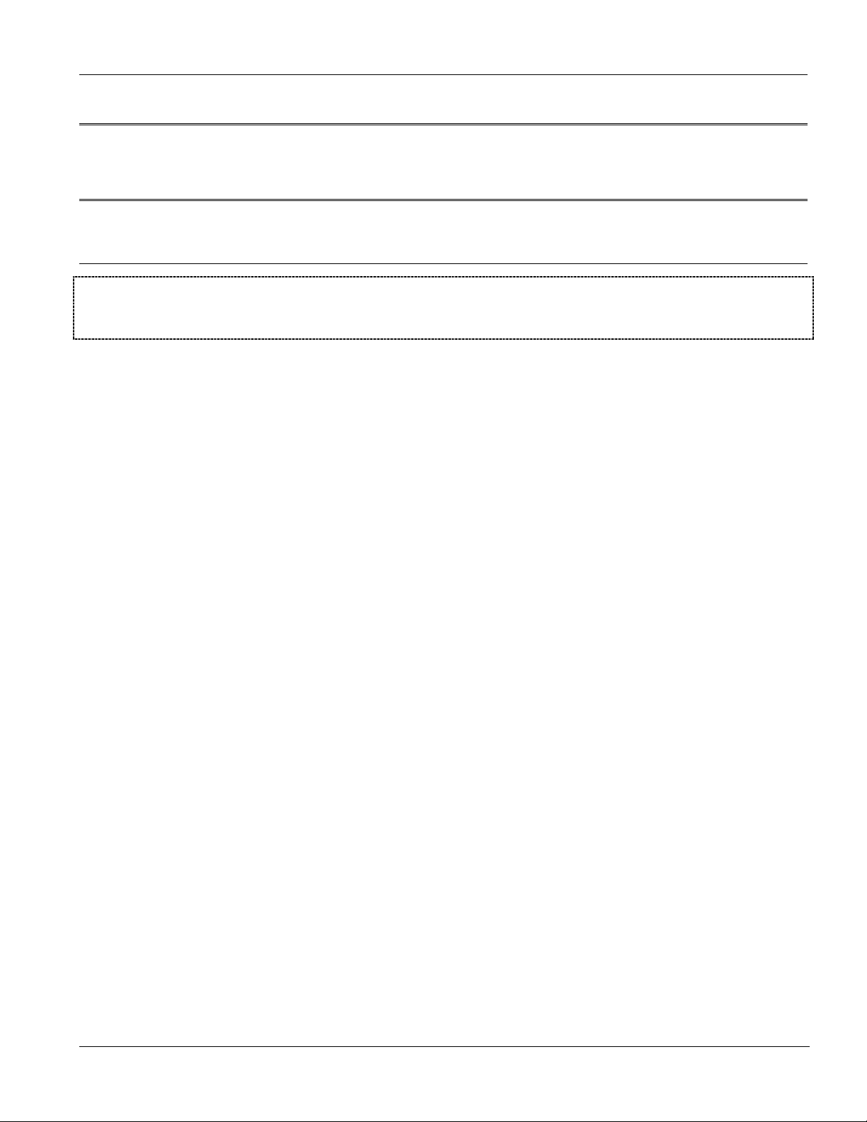
1.2.1 MTU Application
The following figure depicts a typical application for a VDSL-Ethernet Switch in a large residential building, or
Multiple Tenant Unit (MTU), that leverages existing phone line wiring to provide Internet access to all tenants.
A tenant connects a computer to the phone line in a unit using a VDSL modem. The other end of the phone line is
connected to a port on a VES-1000 Series switch. The VES-1000 Series switch aggregates the traffic from the
tenants to the Ethernet port and forwards it to a router or switch. The router (or switch) then routes the traffic
further to the Internet.
Getting to Know the VES-1000 Series 1-3
Page 24
VES-1000 Series Ethernet Switch
Figure 1-1 Building Deployment Example Using a VES-1012
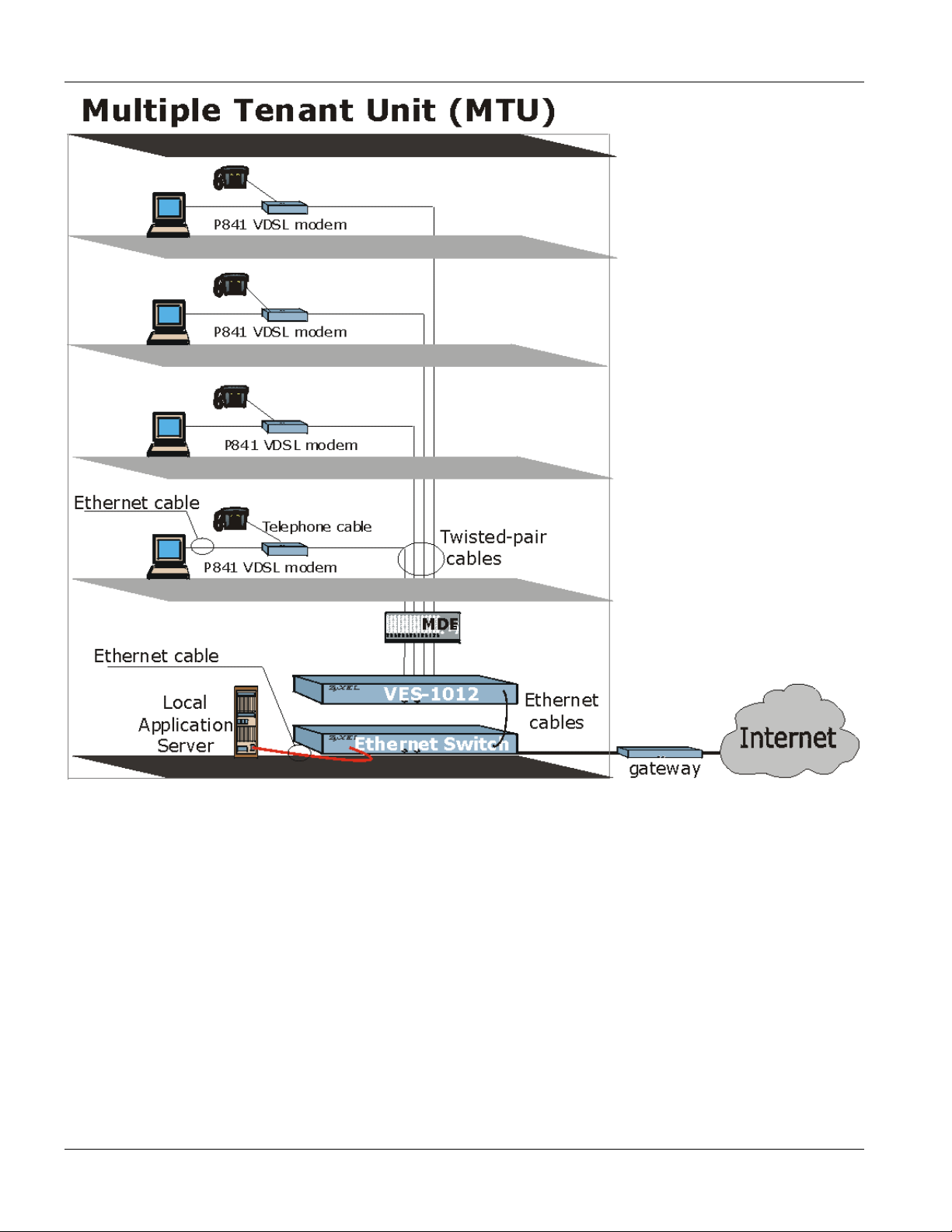
1.2.2 Enterprise Application
The VES-1000 Series of switches can also be used in any-sized company to multiplex employee VDSL
connections to the Internet.
1-4 Getting to Know the VES-1000 Series
Page 25
VES-1000 Series Ethernet Switch
Figure 1-2 Enterprise Application Using a VES-1012
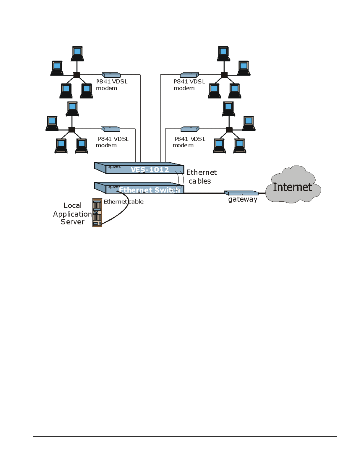
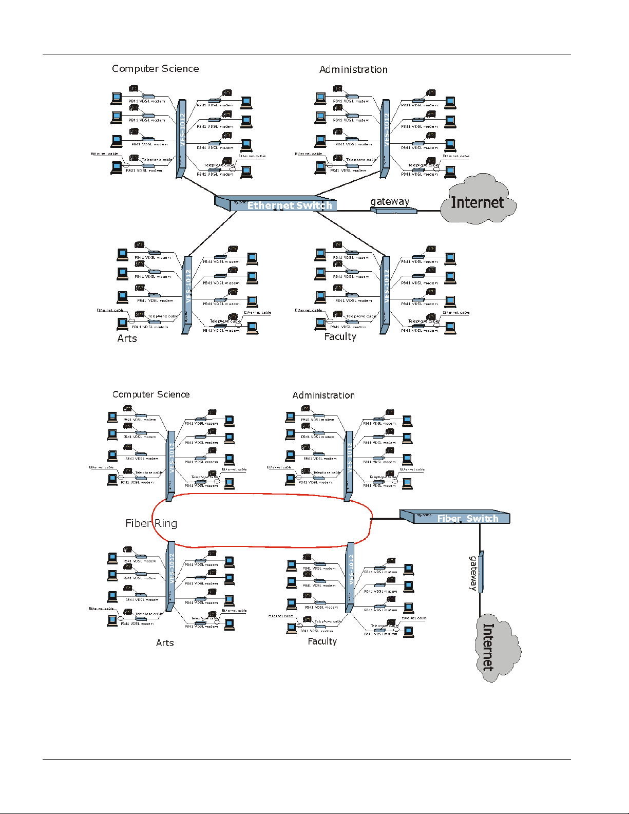
1.2.3 Campus Application
Independent networks can also have VDSL connections multiplexed to a gigabit switch or fiber ring using a VES1000 Series switch.
Getting to Know the VES-1000 Series 1-5
Page 26
VES-1000 Series Ethernet Switch
Figure 1-3 VES-1012 Example of a Campus Application Using a Gigabit switch
Figure 1-4 VES-1012 Example of Campus Application Using a Fiber Ring
1-6 Getting to Know the VES-1000 Series
Page 27
VES-1000 Series Ethernet Switch
Chapter 2
Hardware
This chapter gives a brief introduction to the VES-1000 Series hardware.
Connections
2.1 Additional Installation Requirements
In addition to the contents of the package, you need the following hardware and software components before you
install and use your product:
• A computer with a 10/100M Ethernet NIC (Network Interface Card)
• A computer with terminal emulation software configured to the following parameters:
VT100 terminal emulation
9600 bps
No parity, 8 data bits, 1 stop bit
No flow control
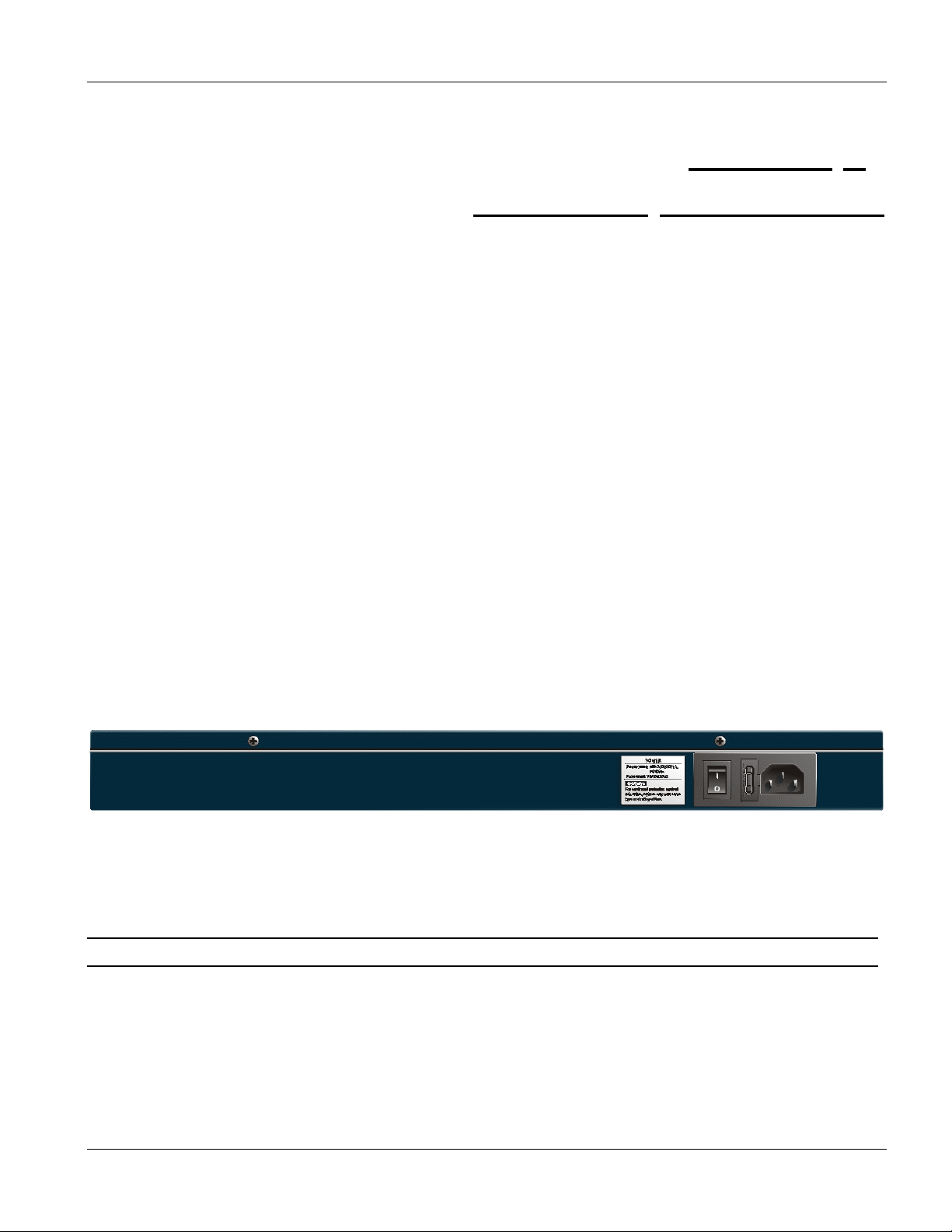
2.2 Back Panel
The following figure shows the back panel for the VES-1012 only. The VES-1008 differs in that the 12 volt DC
power socket is located on the front panel. There are no sockets or switches on the back panel of the VES-1008.
Figure 2-1 VES-1012 Back Panel
2.2.1 Power Connector
Make sure you are using the correct power source.
The VES-1008 has a 12 volt DC power socket located on the front panel. This allows for the convenient placing
of the unit in locations where space may be a limitation. To connect the power to the unit, insert the round end of
the plug on the supplied power adaptor into the power socket on the front panel. Connect the other end of the
supplied power adaptor to a power outlet. Always use the ZyXEL supplied power supply as the VES-1008 may
be damaged if third party power adaptors are used.
Hardware Connections 2-1
Page 28
VES-1000 Series Ethernet Switch
To connect the VES-1012 only, plug the female end of the power cord to the power receptacle on the rear panel.
Connect the other end of the cord to a power outlet. Make sure that no objects obstruct the airflow of the fans
(located on the side of the unit).
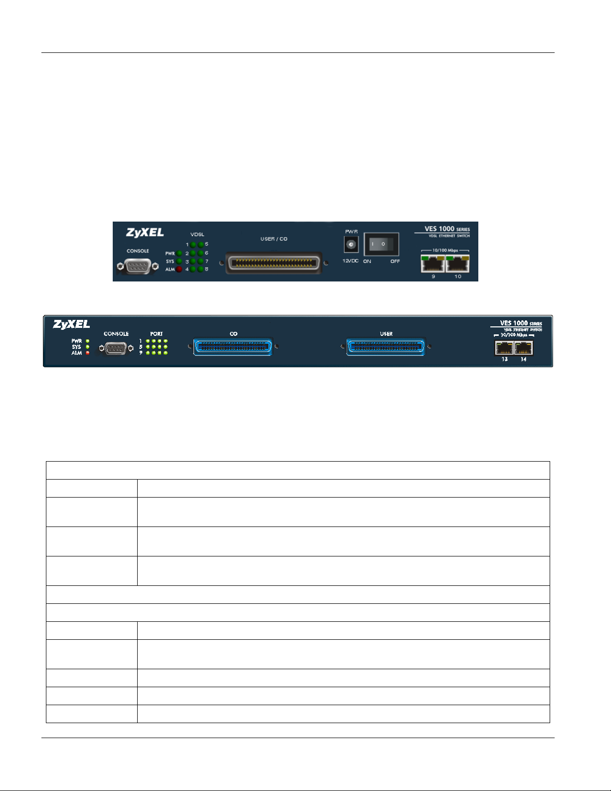
2.3 Front Panel
The following figure shows the front panel of the VES-1012 only. The VES-1008 has a combined USER/CO
Telco-50 connector and displays 8 VDSL ports instead of the 12 that are on the VES-1012. The VES-1008 also
has the socket and switch for the power supply located on the front panel.
Figure 2-2 VES-1008 Front Panel
Figure 2-3 VES-1012 Front Panel
2.4 Front Panel Ports
Table 2-A VES-1000 Series Switches: Front Panel Ports
VES-1008 FRONT PANEL PORTS
CONNECTOR DESCRIPTION
CONSOLE The CONSOLE port is an RS-232 port for local configuration of the VES-1000 Series
switch.
USER/CO The combined USER/CO port is a Telco-50 connector for external POTS/ISDN and VDSL
connections.
Two 10/100 Mbps
RJ-45 connectors
CONNECTOR DESCRIPTION
CONSOLE The CONSOLE port is an RS-232 port for local configuration of the VES-1000 Series
These ports connect to a Ethernet switch or WAN router.
VES-1012 FRONT PANEL PORTS
switch.
CO The CO Telco-50 port connects to the central office or a PBX.
USER The USER Telco-50 port connects to the user (subscriber) VDSL equipment.
Two 10/100 Mbps
These ports connects to a Ethernet switch or WAN router.
2-2 Hardware Connections
Page 29
VES-1000 Series Ethernet Switch
Table 2-A VES-1000 Series Switches: Front Panel Ports
VES-1008 FRONT PANEL PORTS
CONNECTOR DESCRIPTION
CONSOLE The CONSOLE port is an RS-232 port for local configuration of the VES-1000 Series
switch.
USER/CO The combined USER/CO port is a Telco-50 connector for external POTS/ISDN and VDSL
connections.
Two 10/100 Mbps
RJ-45 connectors
CONNECTOR DESCRIPTION
RJ-45 connectors
These ports connect to a Ethernet switch or WAN router.
VES-1012 FRONT PANEL PORTS
2.4.1 Console Port
For the initial configuration, you need to use terminal emulator software on a computer and connect it to the
console port on the VES-1000 Series switch. Connect the male 9-pin end of the console cable to the console port
of the VES-1000 Series switch. Connect the other end (either a female 25-pin or female 9-pin) to a serial port
(COM1, COM2 or other COM port) of your computer. You can use an extension RS-232 cable if the enclosed one
is too short. After the initial setup, you can modify the configuration remotely through a telnet connection.
2.4.2 VDSL Port Connections
The VES-1008 has a combined USER/CO Telco-50 connector and this is used for external POTS/ISDN and
VDSL connections (Appendix B - Diagram 2 shows the pin assignments for the combined Telco-50 connector).
Supplied with the VES-1008 is a cable that is designed to fit into the combined USER/CO socket and it is a
requirement for the installer to configure the other end of the cable to suit their installation requirements.
The Phone Port pins (pins 1-8 and 26-33) connect to the Main Distribution Frame (MDF) that is usually located in
the multi-tenant unit. Eight separate phone connections from different subscribers are available to be used on the
VES-1008 and each of their phone connections are required to be connected to their respective port on the MDF.
The VDSL Port pins are used to connect the VES-1008 to the VDSL modems (for example, ZyXEL’s Prestige
841). As with the phone port pins, each VDSL port requires 2 separate pins. Eight separate VDSL ports are
available on the VES-1008 and each port is available to a separate subscriber or user.
Diagram 2 details the pin assignments for the VES-1008 Phone and VDSL ports.
For the VES-1012 only, connect the lines from the user equipment (VDSL modems) to the
lines from the central office switch or PBX (Private Branch Exchange) to the
CO port. Make sure that the
USER port and the
USER line and the CO lines are not shorted on the MDF (Main Distribution Frame).
Hardware Connections 2-3
Page 30

VES-1000 Series Ethernet Switch
The line from the user carries both the VDSL and the voice signals. For each line, switches in the VES-1000
Series have a built-in splitter that separates the high frequency VDSL signal from the voice band signal and feeds
the VDSL signal to the VES-1000 Series switch, while the voice band signal is diverted to the CO port.
2.4.3 10/100M Auto-Sensing Ethernet
VES-1000 Series switches have two 10/100Mbps auto-sensing Ethernet ports. There are two factors related to
Ethernet: speed and duplex mode. In 10/100Mbps Fast Ethernet, the speed can be 10Mbps or 100Mbps and the
duplex mode can be half duplex or full duplex. The auto-negotiation capability makes one Ethernet port able to
negotiate with a peer automatically to obtain the connection speed and duplex mode that both ends support.
When auto-negotiation is turned on, an Ethernet port on the VES-1000 Series switch negotiates with the peer
automatically to determine the connection speed and duplex mode. If the peer Ethernet port does not support autonegotiation or turns off this feature, the VES-1000 Series switch determines the connection speed by detecting the
signal on the cable and using half duplex mode. When the VES-1000 Series switch’s auto-negotiation is turned
off, an Ethernet port uses the pre-configured speed and duplex mode when making a connection, thus requiring
you to make sure that the settings of the peer Ethernet port are the same in order to connect.
You may also bundle the two Ethernet ports into one logical 200Mbps link.
Default Settings
The factory default settings for the Ethernet ports on the VES-1000 Series switch are:
o Speed: Auto
o Duplex: Auto
o Flow control: On
o Trunking: Disabled
Use a straight through Ethernet cable when connecting the VES-1000 Series switch to an Ethernet switch. Use a
crossover Ethernet cable if you are daisy-chaining the VES-1000 Series switch to another and make sure trunking
is disabled.
2.5 Front Panel LEDs
The following table describes the LED indicators on the front panel of a VES-1000 Series switch.
Table 2-B VES-1000 Series Switches: LED Descriptions
LED COLOR STATUS DESCRIPTION
PWR Green ON
The system is turned on.
OFF
SYS Green Blinking
ON
OFF
2-4 Hardware Connections
The system is off.
The system is rebooting and performing self-diagnostic tests.
The system is on and functioning properly.
The power is off or the system is not ready/malfunctioning.
Page 31

VES-1000 Series Ethernet Switch
Table 2-B VES-1000 Series Switches: LED Descriptions
LED COLOR STATUS DESCRIPTION
ALM Red ON
OFF
VDSL Green Blinking
ON
OFF
10 Mbps Green Blinking
ON
OFF
100 Mbps Yellow Blinking
ON
OFF
There is a hardware failure.
The system is functioning normally.
The system is transmitting/receiving to/from the VDSL modem.
The link to the VDSL modem is up.
The link to the VDSL modem is down.
The system is transmitting/receiving to/from a 10 Mbps Ethernet network.
The link to a 10 Mbps Ethernet network is up.
The link to a 10 Mbps Ethernet network is down.
The system is transmitting/receiving to/from a 100 Mbps Ethernet network.
The link to a 100 Mbps Ethernet network is up.
The link to a 100 Mbps Ethernet network is down.
Hardware Connections 2-5
Page 32

Page 33

VES-1000 Series Ethernet Switch
Chapter 3
Introducing
This chapter shows you how to use the SMT (System Management Terminal) to configure a VES-1000
the SMT
Series Switch.
3.1 Initial Screen
When you turn on your VES-1000 Series switch, it performs several internal tests and initializes the ports. After
the initialization, the VES-1000 Series switch asks you to press [ENTER] to continue, as shown below:
Copyright (c) 2001 ZyXEL Communications Corp.
ethernet address: 00:a0:c5:00:50:02
Press ENTER to continue...
Figure 3-1 Power-On Display
3.1.1 Password
After you press [ENTER], the Login screen appears prompting you to enter the password, as shown in the next
figure.
For your first login, enter the default password “1234”. As you enter the password, the screen displays an (X) for
each character you type.
Enter Password : XXXX
Figure 3-2 Login Screen
Please note that if there is no activity for longer than five minutes after you log in, your VES-1000 Series switch
will automatically log you out and will display a blank screen. If you see a blank screen, press [ENTER] to bring
up the password screen again.
3.2 Navigating the SMT Interface
The SMT (System Management Terminal) is the interface that you use to configure your VES-1000 Series switch.
Several operations that you should be familiar with before you attempt to modify the configuration are listed in the
following table.
Introducing the SMT 3-1
Page 34

VES-1000 Series Ethernet Switch
Table 3-A Navigating the SMT
OPERATION KEYSTROKE DESCRIPTION
Move down to
another menu
Move up to a
previous menu
Move to a “hidden”
menu
Move the cursor [ENTER] or
Entering information Type in or press
Required fields
N/A fields <N/A> Some of the fields in the SMT will show a <N/A>. This symbol refers to
Save your
configuration
Exit the SMT Type 99, then press
[ENTER] To move forward to a submenu, type in the number of the desired
submenu and press [ENTER].
[ESC] Press [ESC] to move back to the previous menu.
Press [SPACE BAR]
to change No to Yes
then press [ENTER].
[UP]/[DOWN] arrow
keys.
[SPACE BAR], then
press [ENTER].
<
?>
[ENTER] Save your configuration by pressing [ENTER] at the message “Press
[ENTER].
Fields beginning with “Edit” lead to hidden menus and have a default
setting of No. Press [SPACE BAR] once to change No to Yes, then
press [ENTER] to go to the “hidden” menu.
Within a menu, press [ENTER] to move to the next field. You can also
use the [UP]/[DOWN] arrow keys to move to the previous and the next
field, respectively.
You need to fill in two types of fields. The first requires you to type in
the appropriate information. The second allows you to cycle through
the available choices by pressing [SPACE BAR].
All fields with the symbol <?> must be filled in order to be able to save
the new configuration.
an option that is Not Applicable.
ENTER to confirm or ESC to cancel”. Saving the data on the screen
will take you, in most cases to the previous menu.
Type 99 at the main menu prompt and press [ENTER] to exit the SMT
interface.
3.3 SMT Menus At A Glance
The following figure gives an overall view of how the SMT menus are organized.
3-2 Introducing the SMT
Page 35

VES-1000 Series Ethernet Switch
Figure 3-3 SMT Menus At A Glance
3.3.1 VES-1000 Series switch Main Menu
After you log in, the SMT displays a main menu.
Introducing the SMT 3-3
Page 36

VES-1000 Series Ethernet Switch
Getting Started Advanced Management
1. General Setup
2. Switch Setup 22. SNMP Configuration
3. IP Setup 23. System Password
24. System Maintenance
6. Port Setup
Advanced Applications
12. Static Routing Setup
17. VLAN Setup
99. Exit
Enter Menu Selection Number:
Copyright (c) 2000,2001 ZyXEL Communications Corp.
VES-1012 Main Menu (VDSL_1)
Figure 3-4 VES-1012 Main Menu
The following table shows the VES-1000 Series switch Main Menu summary:
Table 3-B Main Menu Summary
# MENU TITLE DESCRIPTION
1 General Setup Use this menu to enter VES-1000 Series switch administrative information.
2 Switch Setup Use this menu to set the switch parameters, including STP setup, GARP timers
and QS parameters.
3 IP Setup Use this menu to set up TCP/IP parameters such as the IP address, subnet
mask and default gateway.
6 Port Setup Configure your VDSL and Ethernet ports in this menu including individual port
STP configuration.
12 Static Routing Setup Use this menu to set up static routes.
17 VLAN Setup Configure switch VLAN setup in this menu.
22 SNMP Configuration Use this menu to set up SNMP related parameters
23 System Password Use this menu to change your system password.
24 System Maintenance Configure menus for System Status, System Information/Console Port Speed,
Log and Trace, Diagnostic, Backup, Restore, Firmware Update, Command
Interpreter Mode, Time and Date Setting, Remote Management Control and
Hardware Monitor here.
99 Exit To exit a system configuration/management session via SMT you must type 99.
You then return to a blank screen.
3.4 Changing the System Password
It’s important to change the default system password by doing the following:
Step 1. Enter 23 from the main menu. This will open Menu 23 – Change Password as shown next.
Step 2. Type the existing system password (“1234” is the default password when shipped), then press
[ENTER].
3-4 Introducing the SMT
Page 37

VES-1000 Series Ethernet Switch
Menu 23 — Change Password
Old Password= XXXX
New Password= XXXX
Retype to confirm= XXXX
Press ENTER to Confirm or ESC to Cancel:
Figure 3-5 Menu 23.1 - System Password
Step 3. Enter your new system password and press [ENTER].
Step 4. Re-type your new system password for confirmation and press [ENTER].
3.4.1 Resetting the VES-1000 Series switch
If you forget your password or cannot access the VES-1000 Series switch, you will need to reload the factorydefault configuration file. Uploading this configuration file replaces the current configuration file with the factorydefault configuration file. This means that you will lose all configurations that you had previously and the speed of
the console port will be reset to the default of 9600bps with 8 data bit, no parity, one stop bit and flow control set
to none. The password will also be reset to “1234” and the IP address to 192.168.1.1.
To obtain the default configuration file, download it from the ZyXEL FTP site, unzip it and save it in a folder.
Turn the VES-1000 Series switch off and then on to begin a session. When you turn on the VES-1000 Series
switch again you will see the initial screen. When you see the message “Press any key to enter Debug Mode
within 3 seconds” press any key to enter debug mode.
To upload the configuration file, do the following:
1. Type atlc after the Enter Debug Mode message.
2. Wait for the Starting XMODEM upload message before activating XMODEM upload on your terminal.
3. After a successful firmware upload, type atgo to restart the VES-1000 Series switch.
The VES-1000 Series switch is now reinitialized with a default configuration file including the default password
of “1234”.
Introducing the SMT 3-5
Page 38

VES-1000 Series Ethernet Switch
Part II:
Getting Started
This part shows you how to configure the General Setup, Switch Setup, IP Setup and Port
Setup SMT menus.
II
Page 39

VES-1000 Series Ethernet Switch
Chapter 4
General,
Switch and IP Setup
This chapter describes SMT menus 1, 2 and 3.
4.1 General Setup
Use this menu to enter the administrative information for VES-1000 Series switch.
From the main menu enter 1 to bring up Menu 1 – General Setup.
Menu 1 – General Setup
System Name = VDSL_1
Location = Hsinchu
Contact Person’s Name = JohnDoe
Press Enter to Confirm or ESC to Cancel:
Figure 4-1 Menu 1 – General Setup
The Menu 1 — General Setup fields are explained in the next table.
Table 4-A General Setup Fields
FIELD DESCRIPTION EXAMPLE
System Name Choose a descriptive name for identification purposes. This name can be up
to 30 alphanumeric characters long. Spaces are not allowed, but dashes “-”
and underscores "_" are accepted. This name can be retrieved remotely via
SNMP and will be displayed up to the first 9 characters at the prompt in the
Command Mode.
Note: Once you have configured the System Name, you can see it displayed (up to the first nine characters) in the
main menu within brackets next to " VES-1012 Main Menu”.
Location
(optional)
Contact Person's
Name (optional)
When you have completed this menu, press [ENTER] at the prompt “Press ENTER to Confirm…” to save your
configuration, or press [ESC] at any time to cancel.
Enter the geographic location (up to 31 characters) of your VES-1000 Series
switch.
Enter the name (up to 30 characters) of the person in charge of this VES1000 Series switch.
VDSL_1
Hsinchu
JohnDoe
4.2 Switch Setup
Enter 2 from the main menu to display Menu 2 – Switch Setup.
General, Switch and IP Setup 4-1
Page 40

VES-1000 Series Ethernet Switch
Menu 2 - Switch Setup
VDSL Mode= 10BaseS
VDSL Modem Firmware Auto Upgrade= Yes
Ethernet Port 13 and Port 14 Trunking= No
Edit Spanning Tree Protocol= No
Edit GARP Timer= No
VLAN Type= 802.1Q
IGMP Snooping= Disable
Edit QoS Support= No
Press ENTER to Confirm or ESC to Cancel:
Press Space Bar to Toggle.
Figure 4-2 Menu 2 - Switch Setup
Table 4-B Menu 2 – Switch Setup
FIELD DESCRIPTION EXAMPLE
VDSL Mode Press [SPACE BAR] and then press [ENTER] to choose from
10BaseS, ETSI Plan 997 or ANSI/ETSI Plan 998.
VDSL Modem Firmware
Auto Upgrade
Ethernet Port 13 and Port
14 Trunking
Press [SPACE BAR], select Yes, and then press [ENTER] to allow
automatic firmware upgrade of the subscribers VDSL modem.
Ethernet port trunking is disabled by default. Press [SPACE BAR],
select Yes, and then press [ENTER] to allow trunking (make sure the
remote switch also supports trunking).
Enable trunking (press [SPACE BAR], select Yes) only if you connect
both Ethernet ports to a single switch. (Ethernet ports 13 & 14 relate
to the VES-1012 switch only).
Edit Spanning Tree
Protocol
Press [SPACE BAR] once to select Yes and then [ENTER] to display
Menu 2.1 - Spanning Tree Protocol Setup.
Edit GARP Timer Press [SPACE BAR] once to select Yes and then press [ENTER] to
go to Menu 2.2 — GARP Timer Setup.
VLAN Type Press [SPACE BAR] and then press [ENTER] to choose from 802.1Q
or Port-Based. See section 4.2.8 for more information on VLANs. To
enable IEEE 802.1Q on the VES-1000 Series switch, you must
configure it for the switch in this menu, menu 6 port submenu(s) and
menu 17 VLAN setup. Menu 17 is not applicable (N/A) if you choose
port-based VLANs for the switch in menu 2.
10BaseS
Yes
No
No
No
802.1Q
IGMP Snooping Press [SPACE BAR] once to select Enable and then press [ENTER].
Disable
Press [ENTER] again at the message “Press ENTER to Confirm…“ to
activate IGMP snooping on the device.
Edit QoS Support Press [SPACE BAR] once to select Yes and then press [ENTER to
No
go to Menu 2.3 — QoS Setup.
When you have completed this menu, press [ENTER] at the prompt “Press ENTER to Confirm…” to save your
configuration, or press [ESC] at any time to cancel.
4-2 General, Switch and IP Setup
Page 41

VES-1000 Series Ethernet Switch
4.2.1 VDSL Mode
Each VDSL mode operates in a different frequency band allocation, resulting in different upstream and
downstream speeds. The following table summarizes transmission speeds and frequency ranges for each VDSL
mode supported by the VES-1000 Series switch.
Table 4-C VDSL Mode, Frequency Ranges and Speeds
VDSL MODE FREQ. RANGE (Hz) LINE SPEED (Mbps)
10 Base-S
Upstream 4.0M 7.9M 1.56 6.25 9.38 12.50 18.75
Downstream 900K 3.0M 4.17 6.25 8.33 12.50 16.67
ANSI/ETSI Plan 998
Upstream 4.0M 5.0M 1.56 3.13 6.25
Downstream 900K 3.0M 4.17 6.25 8.33 12.50 16.67
ETSI Plan 997
Upstream 4.0M 5.0M 1.56 3.13 6.25
Downstream 900K 2.7M 4.17 6.25 9.38 12.50
4.2.2 Modem Firmware Upgrade
This option enables the uploading of VDSL modem firmware (the default is No) if the subscribers VDSL modem
firmware is an older version than that of the VES-1000 Series switch. This ensures that all VDSL clients on the
VES-1000 Series switch have the same firmware as the actual switch and avoids potential compatibility conflicts.
4.2.3 Ethernet Port Trunking
Ethernet port trunking lets you aggregate the Ethernet ports into one logical link. The VES-1000 Series switch
uses MAC-based load balancing which analyzes a packet’s source and destination MAC addresses to distribute the
load between the two Ethernet ports when uplinking to the remote switch.
The remote switch to which the VES-1000 Series switch connects must also support Ethernet
port trunking. The load-balancing method, however, does not have to be the same as on the
VES-1000 Series switch.
Note that the two uplink ports must be connected to a single remote switch when port trunking is enabled. Disable
trunking (default) if you wish to daisy-chain other VES-1000 Series VDSL switches. Daisy-chaining VES-1000
Series switches does degrade performance.
General, Switch and IP Setup 4-3
Page 42

VES-1000 Series Ethernet Switch
4.2.4 STP (Spanning Tree Protocol)
The use of STP in the majority of network environments is not recommended. Furthermore, this rarely used
feature should not be enabled on the VDSL ports on the VES-1000 Series of switches.
STP detects and breaks network loops and provides backup links between switches, bridges or routers. It allows a
device to interact with other STP-aware devices in your network to ensure that only one path exists between any
two stations on the network.
The root bridge is the base of the spanning tree; it is the bridge with the lowest identifier value (MAC address).
Path cost is the cost of transmitting a frame onto a LAN through that port. It is assigned according to the speed of
the link to which a port is attached. The slower the media, the higher the cost - see the following table.
Table 4-D Path Cost
LINK SPEED RECOMMENDED VALUE RECOMMENDED RANGE ALLOWED RANGE
Path Cost 4Mbps 250 100 to 1000 1 to 65535
Path Cost 10Mbps 100 50 to 600 1 to 65535
Path Cost 16Mbps 62 40 to 400 1 to 65535
Path Cost 100Mbps 19 10 to 60 1 to 65535
Path Cost 1Gbps 4 3 to 10 1 to 65535
Path Cost 10Gbps 2 1 to 5 1 to 65535
On each bridge, the root port is the port through which this bridge communicates with the root. It is the port on
this switch with the lowest path cost to the root (the root path cost). If there is no root port, then this switch has
been accepted as the root bridge of the spanning tree network.
For each LAN segment, a designated bridge is selected. This bridge has the lowest cost to the root among the
bridges connected to the LAN.
After a bridge determines the lowest cost-spanning tree with STP, it enables the root port and the ports that are the
designated ports for the connected LANs, and disables all other ports that participate in STP. Network packets are
therefore only forwarded between enabled ports, eliminating any possible network loops.
4-4 General, Switch and IP Setup
Page 43

VES-1000 Series Ethernet Switch
Figure 4-3 Root Ports and Designated Ports
STP-aware devices exchange Bridge Protocol Data Units (BPDUs) periodically. When the bridged LAN topology
changes, a new spanning tree is constructed.
Once a stable network topology has been established, all devices listen for Hello BPDUs transmitted from the root
bridge. If a device does not get a Hello BPDU after a predefined interval (Max Age), the device assumes that the
link to the root bridge is down. This device then initiates negotiations with other devices to reconfigure the
network to re-establish a valid network topology.
STP assigns five port states (see following table) to eliminate packet looping. A device port is not allowed to go
directly from blocking state to forwarding state so as to eliminate transient loops.
Table 4-E Port States
PORT STATE DESCRIPTION
Disabled STP is disabled (default).
Blocking Only configuration and management BPDUs are received and processed.
Listening All BPDUs are received and processed.
Learning
Forwarding All BPDUs are received and processed. All information frames are received and forwarded.
All BPDUs are received and processed. Information frames are submitted to the learning process
but not forwarded.
4.2.5 Configuring STP on the VES-1000 Series Switch
To configure STP on the VES-1000 Series switch, select 2 from the main menu, go to the Edit Spanning Tree
Protocol field, press [SPACE BAR] once to select Yes and then [ENTER] to display Menu 2.1 - Spanning Tree
Protocol Setup menu.
General, Switch and IP Setup 4-5
Page 44

VES-1000 Series Ethernet Switch
Menu 2.1 - Spanning Tree Protocol Setup
Spanning Tree Protocol= Disable
Bridge Priority= 32768
Bridge Hello Time(Time (sec)= 2
Bridge Max Age(Age (sec)= 20
Forward Delay(Delay (sec)= 15
Press ENTER to Confirm or ESC to Cancel:
Press Space Bar to Toggle.
Figure 4-4 Menu 2.1 Spanning Tree Protocol Setup
Table 4-F Menu 2.1 - Spanning Tree Protocol Setup
FIELD DESCRIPTION EXAMPLE
Spanning Tree
Protocol
Bridge Priority Bridge priority is used in determining the root device, root port and designated
Hello Time This is the time interval in seconds between configuration message generated
Press [SPACE BAR] to toggle between Enable and Disable.
port. The device with the highest priority (lowest numeric value) becomes the
STP root device. If all devices have the same priority, the device with the lowest
MAC address will then become the root device. The allowed range is 0 to 65535.
The lower the numeric value you assign, the higher the priority for this bridge.
by the root device. The allowed range is 1 to 10 seconds.
Disable
32768 (default)
2 (default)
Max Age This is the maximum time (in seconds) a device waits without receiving a BPDU
before attempting to reconfigure. All device ports (except for designated ports)
should receive BPDUs at regular intervals. Any port that ages out STP
information (provided in the last BPDU) becomes the designated port for the
attached LAN. If it is a root port, a new root port is selected from among the
Forwarding
Delay
device ports attached to the network. The allowed range is 6 to 40 seconds.
This is the maximum time (in seconds) a device waits before changing states.
This delay is required because every device must receive information about
topology changes before it starts to forward frames. In addition, each port needs
time to listen for conflicting information that would make it return to a blocking
state; otherwise, temporary data loops might result. The allowed range is 4 to 30
seconds.
20 (default)
15 (default)
Bridge Priority determines the root bridge, which in turn determines Hello Time, Max Age and
Forwarding Delay.
4.2.6 GARP Timer Setup
GARP (Generic Attribute Registration Protocol) allows network devices to register and de-register attribute values
with other GARP participants within a bridged LAN. GARP is a protocol that provides a generic mechanism for
protocols that serve a more specific application, for example, GVRP (GARP VLAN Registration Protocol).
GARP and GVRP are the protocols used to automatically register VLAN membership across switches.
Switches join VLANs by making a declaration. A declaration is made by issuing a Join message using GARP.
Declarations are withdrawn by issuing a Leave message. A Leave All message terminates all registrations. GARP
timers set declaration timeout values.
4-6 General, Switch and IP Setup
Page 45

VES-1000 Series Ethernet Switch
Select Yes in the Edit GARP Timer field in menu 2 to go to Menu 2.2 — GARP Timer Setup.
Join Timer(Timer (msec)= 200
Leave Timer(Timer (msec)= 600
Leave All Timer(Timer (msec)= 10000
Press ENTER to Confirm or ESC to Cancel:
The Range of Join Timer is between 100 and 65535.
Menu 2.2 - GARP Timer Setup
Figure 4-5 Menu 2.2 GARP Timer Setup
Table 4-G Menu 2.2 - GARP Timer
FIELD DESCRIPTION EXAMPLE
Join Timer Join Timer sets the duration of the Join Period timer for GARP in milliseconds.
Each port has a Join Period timer. The allowed Join Time range is between
100 and 65535 milliseconds; the default is 200 milliseconds.
Leave Timer Leave Timer sets the duration of the Leave Period timer for GARP in
milliseconds. Each port has a single Leave Period timer. Leave Timer must be
at least two times larger than Join Timer; the default is 600 milliseconds.
Leave All Timer Leave All Timer sets the duration of the Leave All Period timer for GARP in
milliseconds. Each port has a single Leave All Period timer. Leave All Timer
must be larger than Leave Timer; the default is 10,000 milliseconds.
200 (default)
600 (default)
10000
(default)
Once you have completed filling in Menu 2.2 — GARP Timer Setup, press [ENTER] at the message “Press
ENTER to Confirm… “ to save your configuration or press [ESC] at any time to cancel.
4.2.7 GVRP
GVRP (GARP VLAN Registration Protocol) is a registration protocol that defines a way for switches to register
necessary VLAN members on ports across the network. Enable this function to permit VLANs groups beyond the
local switch. Please refer to the following table for common GVRP terminology.
Table 4-H GVRP Terminology
VLAN Type Permanent VLAN This is a static VLAN created manually.
Dynamic VLAN This is a VLAN configured by a GVRP
registration/deregistration process.
VLAN Administrative
Control
Registration Forbidden Ports with registration forbidden are not allowed to register
Normal Registration Ports join a VLAN using GVRP.
VLAN Tag Control Tagged Ports tag all (VLAN member) egress frames transmitted.
Registration Fixed Fixed registration ports are permanent VLAN members.
(join) this VLAN.
Untagged Ports don’t tag all (VLAN member) egress frames transmitted.
General, Switch and IP Setup 4-7
Page 46

VES-1000 Series Ethernet Switch
VLAN Port Port VID This is the VLAN ID assigned to untagged frames that this port
receives.
Acceptable frame type Whether tagged only or both untagged frames are accepted on
this port.
Ingress filtering If set, the device discards incoming frames for VLANs which do
not include this port in its member set.
4.2.8 VLANs
A VLAN (Virtual Local Area Network) allows a physical network to be partitioned into multiple logical networks.
Stations on a logical network belong to one group. A station can belong to more than one group. With VLAN, a
station cannot directly talk to or hear from stations that are not in the same group(s); the traffic must first go
through a router.
In MTU applications, VLAN is vital in providing isolation and security among the subscribers. When properly
configured, VLAN prevents one subscriber from accessing the network resources of another on the same LAN,
thus a user will not see the printers and hard disks of another user in the same building.
VLANs also increase network performance by limiting broadcasts to a smaller and more manageable logical
broadcast domain. In traditional switched environments, all broadcast packets go to each and every individual
port. With VLAN, broadcasts are confined to the members of the VLAN. Note that VLANs are unidirectional they only govern outgoing traffic.
Port-based VLANS
Port-based VLANs are VLANs where the packet forwarding decision is based on the destination MAC address
and its associated port.
As previously mentioned, VLANs are unidirectional. Therefore, if you wish to allow two subscriber ports to talk
to each other, for example, between conference rooms in a hotel, you must define the egress (an egress port is an
outgoing port, that is, a port through which a data packet leaves) for both ports.
Port-based VLANs are specific only to the switch on which they were created. The factory default port-based
VLAN settings for VES-1000 Series switches are summarized below.
• Port 0 (the CPU management port) forms a VLAN with uplink ports and can use all Ethernet ports as the
uplink.
• The VDSL ports cannot talk to each other.
• Each VDSL port forms a VLAN with the Ethernet ports and vice-versa.
Tagged VLANs (IEEE 802.1Q)
Tagged VLAN uses an explicit tag (VLAN ID) in the MAC header to identify the VLAN membership of a frame
across bridges – they are not confined to the switch on which they were created. The VLANs can be created
statically by hand or dynamically through GVRP. The VLAN ID associates a frame with a specific VLAN and
4-8 General, Switch and IP Setup
Page 47

VES-1000 Series Ethernet Switch
provides the information that switches need to process the frame across the network. A tagged frame is four bytes
longer than an untagged frame and contains two bytes of TPID (Tag Protocol Identifier; residing within the
type/length field of the Ethernet frame) and two bytes of TCI (Tag Control Information; a tagged header starts
after the source address field of the Ethernet frame).
TPID
2 bytes
User Priority
3 bits
CFI
1 bit
VLAN ID
12 bits
TPID has a defined value of 8100 (hex). The first three bits of the TCI define user priority (giving eight priority
levels). The CFI (Canonical Format Indicator) is a single-bit flag, always set to zero for Ethernet switches. The
12
remaining twelve bits define the VLAN ID, giving a possible maximum number of 4,096 (2
) VLANs.
Note that user priority and VLAN ID are independent of each other. A frame with VID (VLAN Identifier) of null
(0) is called a priority frame, meaning that only the priority level is significant and the default VID of the ingress
port is given as the VID of the frame.
Of the 4096 possible VIDs, a VID of 0 is used to identify priority frames and value 4095 (FFF) is reserved, so the
maximum possible VLAN configurations are 4,094.
Each port on the switch is capable of receiving tagged or untagged frames. You can configure a VES-1000 Series
switch to receive only tagged or all frames on a port-by-port basis. If it is set to tagged-only on a port, then only
tagged frames are allowed to enter from that port and untagged frames are dropped; if set to all, then both tagged
and untagged frames are allowed to enter the switch. The VES-1000 Series switch does not alter the VID of a
frame if it is already tagged; however, when an untagged frame enters the switch, it is assigned the default port
VID (PVID) of the ingress (incoming) port. Thus a frame always has a VID inside the switch, regardless of
whether it is tagged or not on the wire. The default PVID is 1 for all ports, but this can be changed.
The egress (outgoing) port(s) of a frame is determined on the combination of the destination MAC address and the
VID of the frame. For a unicast frame, the egress port based by the destination address must be a member of the
VID, also; otherwise, the frame is blocked. For a broadcast (or multicast without IGMP snooping) frame, it is
duplicated only on ports (except the ingress port itself) that are members of the VID, thus confining the broadcast
to a specific domain.
Whether to tag an outgoing frame depends on the setting of the egress port on a per VLAN, per port basis (recall
that a port can be members of multiple VID). If the tagging on the egress port is enabled for the VID of a frame,
then the frame is transmitted as a tagged frame; otherwise, it is transmitted as an untagged frame.
General, Switch and IP Setup 4-9
Page 48

VES-1000 Series Ethernet Switch
Figure 4-6 Forwarding Tagged/Untagged Frames to 802.1Q VLAN Aware/Unaware Devices
4.2.9 Quality of Service (QoS)
IEEE 802.1p defines up to 8 separate traffic classes by inserting a tag into a MAC-layer frame that contains bits to
define class of service.
Table 4-I QoS Priority Listing
Priority 7 Typically used for network control traffic such as router configuration messages.
Priority 6 Typically used for voice traffic that is especially sensitive to jitter (jitter is the variations in delay.
Priority 5 Typically used for video that consumes high bandwidth and is sensitive to jitter.
Priority 4 Typically used for controlled load, latency-sensitive traffic such as SNA transactions.
Priority 3 Typically used for better than best effort; would include important business traffic that can tolerate
some delay.
Priority 2 Typically used for best-effort traffic.
Priority 1 This is the default priority if none is specified.
Priority 0 Typically used for non-critical traffic such as backups, non-critical replications, some electronic mail
and so on.
The switch has 4 physical queues to support the 8 priority levels for each port. On the switch, traffic assigned to
higher index queues gets through faster while traffic in lower index queues is dropped if the network is congested.
You use menu 2.3 to map the priority levels to physical queues.
Frames without explicit priority is given the default priority of the ingress port. You can use menu 6.1 and 6.2 to
configure the default priority for each port.
To configure the priority level-to-physical queue mapping, select Yes in the Edit QoS Support field in menu 2 to
go to Menu 2.3 — QoS Setup. The following figure displays the default queues for each priority level.
4-10 General, Switch and IP Setup
Page 49

VES-1000 Series Ethernet Switch
Priority Queue Assignment
Priority Level 7= Queue 3
Priority Level 6= Queue 3
Priority Level 5= Queue 2
Priority Level 4= Queue 2
Priority Level 3= Queue 1
Priority Level 2= Queue 0
Priority Level 1= Queue 0
Priority Level 0= Queue 1
Press ENTER to Confirm or ESC to Cancel:
Menu 2.3 - QoS Setup
Figure 4-7 Menu 2.3 QoS Setup
Table 4-J Menu 2.3 - QoS Setup
FIELD DESCRIPTION EXAMPLE
Priority
Level 7 to 0
Once you have completed configuring Menu 2.2 — QoS Setup, press [ENTER] at the message “Press ENTER to
Confirm… “ to save your configuration or press [ESC] at any time to cancel.
Configure the priority-to-queue assignment for each port in this menu by pressing
[SPACE BAR] to select a queue (Queue 0 to Queue 3) and then pressing
[ENTER]. Queue 3 has the highest priority. Traffic assigned to higher index queue
gets through faster while traffic assigned to lower index queue is dropped if the
network is congested.
Queue 3
4.3 TCP/IP Setup
From the main menu enter 1 to bring up Menu 3 – TCP/IP Setup.
4.3.1 TCP/IP Setup Parameters
The VES-1000 Series switch needs a static IP address for it to be managed over the network. The factory default
IP address is 192.168.1.1. The administrator needs to assign a static IP address for the VES-1000 Series switch.
The subnet mask specifies the network number portion of an IP address. Your VES-1000 Series switch computes
the subnet mask automatically based on the IP address that you entered. You don’t need to change the subnet
mask computed by the VES-1000 Series switch unless you are instructed to do otherwise. The factory default
subnet mask is 255.255.255.0.
The default gateway specifies the IP address of the default gateway (next hop) for outgoing traffic. The default
gateway is specified as 192.168.1.254.
General, Switch and IP Setup 4-11
Page 50

VES-1000 Series Ethernet Switch
Menu 3 – TCP/IP Setup
TCP/IP Setup:
IP Address = 192.168.1.1
IP Subnet Mask = 255.255.255.0
Default Gateway = 192.168.1.254
Press ENTER to Confirm or ESC to Cancel:
Figure 4-8 Menu 3 – TCP/IP Setup
The Menu 3 – TCP/IP Setup fields are explained in the next table:
Table 4-K LAN TCP/IP Setup Menu Fields
FIELD DESCRIPTION EXAMPLE
TCP/IP Setup
IP Address Enter the IP address of your VES-1000 Series switch in dotted decimal
192.168.1.1
notation.
IP Subnet Mask Your VES-1000 Series switch automatically calculates the subnet mask
based on the IP address that you assign. Unless you are implementing
subnetting, use the subnet mask computed by the VES-1000 Series
255.255.255.0
switch.
Default Gateway Enter the IP address of the default outgoing gateway in dotted decimal
192.168.1.254
notation.
When you have completed this menu, press [ENTER] at the prompt “Press ENTER to Confirm…” to save your
configuration, or press [ESC] at any time to cancel.
4-12 General, Switch and IP Setup
Page 51

VES-1000 Series Ethernet Switch
Chapter 5
Port
Configure your VDSL and Ethernet ports in SMT menu 6.
Setup
5.1 Configured Vs. Actual VDSL Port Speed
Configure the maximum speed of an individual VDSL port in this menu. Due to noise and other factors on the
line, the actual speed may not reach the maximum that you specify. See Table 4-C VDSL Mode, Frequency
Ranges and Speeds for the range of speeds you may configure for each VDSL mode.
Enter 6 from the main menu to bring up Menu 6 – Ports Setup.
Menu 6 – Ports Setup
Type Active User Name
1. VDSL Yes JoeSoap
2. VDSL Yes David
3. VDSL Yes Troy
4. VDSL No John
5. VDSL No ____________
6. VDSL No ____________
7. VDSL No ____________
8. VDSL No ____________
9. VDSL No ____________
10. VDSL No ____________
11. VDSL No ____________
12. VDSL No ____________
13. Ethernet Yes Uplink1
14. Ethernet Yes Uplink2
Enter selection Number :
Figure 5-1
Menu 6 – Ports Setup for VES-1012 Only
5.2 Port Configuration
Port type (VDSL or Ethernet) is labeled under Type in menu 6. Enter the port index number to configure it.
This menu only shows the number of ports that are available on your particular VES-1000 Series switch. As an
example, the VES-1008 will show eight available ports and the VES-1012 will show twelve available ports.
5.2.1 VDSL Port Configuration
Select a VDSL port and then press [ENTER] to go to the VDSL port setup menu.
Port Setup 5-1
Page 52

VES-1000 Series Ethernet Switch
Menu 6.1 - VDSL Port Setup
User Name= JoeSoap
Active= No
Type= VDSL (r.o.)
Speed:
Upstream= 12500K
Downstream= 12500K
Edit Spanning Tree Protocol Setup= No
Edit VLAN Setup= No
Default Port Priority= 0
Press ENTER to Confirm or ESC to Cancel:
Figure 5-2 VDSL Port Setup
The Menu 6.1 – VDSL Port Setup fields are explained in the next table.
Table 5-A VDSL Port Setup
FIELD DESCRIPTION EXAMPLE
User Name Choose a descriptive name for identification purposes. This name can be
up to 30 alphanumeric characters long. Spaces are not allowed, but
dashes “-” and underscores "_" are accepted.
Active The factory default of all VDSL ports is disabled. A port must be enabled
for data transmission to occur. Press [SPACE BAR] to select Yes and
press [ENTER] to enable the specified VDSL port.
Type This read-only (r.o.) field displays the type of port you are currently
configuring. (Ethernet Ports 13 and 14 relate to the VES-1012 only).
Speed:
Upstream Press [SPACE BAR] to cycle through the upstream speeds. Speeds
available depend on the VDSL Mode chosen in Menu 2 – Switch Setup.
Please refer to Table 4-C VDSL Mode, Frequency Ranges and Speeds.
Downstream Press [SPACE BAR] to cycle through the downstream speeds available for
the VDSL Mode chosen in Menu 2 – Switch Setup.
Edit Spanning
Tree Protocol
Setup
Press [SPACE BAR] once to select Yes and then press [ENTER] to go to
Menu 6.1 - Port Spanning Tree Protocol Setup. You must enable STP
on the switch (in menu 2) before you configure it on a port(s). Note that
you very rarely need to enable STP on VDSL ports since the VDSL ports
are directly connected to the users.
Edit VLAN Setup Press [SPACE BAR] once to select Yes and then press [ENTER] to open
Menu 6.1.3 — Port VLAN Setup.
JoeSoap
Yes
VDSL
9380K
8333K
No
No
Default Port
Priority
The Default Port Priority value is added to incoming frames without a
(802.1p) priority tag. The default is 0. Use this field to define the default
0
priority of each port.
When you have completed this menu, press [ENTER] at the prompt “Press ENTER to Confirm…” to save your
configuration, or press [ESC] at any time to cancel.
5-2 Port Setup
Page 53

VES-1000 Series Ethernet Switch
p
5.2.2 Ethernet Port Setup
Ethernet port connections can be half duplex or full duplex. The Ethernet port must use the same speed / duplex
mode setting as the peer Ethernet port in order to connect.
Please refer to section 2.4.3 for Ethernet port default settings and section 4.2.3 for information on port trunking.
Select an Ethernet port and then press [ENTER] to go to the Ethernet port setup menu.
Menu 6.13 – Ethernet Port Setup
User Name = Uplink1
Active = Yes
Type = ETHERNET (r.o)
Speed = Auto
Duplex = Auto
Flow Control = Yes
Edit Spanning Tree Protocol Setup= No
Edit VLAN Setup= No
Default Port Priority= 0
Press Enter to Confirm or ESC to Cancel:
Menu 6.13 – Ethernet Port Setup
The Menu 6.13
Figure 5-3
– VDSL Port Setup fields are explained in the next table.
Table 5-B Menu 6.13 – Ethernet Port Setup
FIELD DESCRIPTION EXAMPLE
User Name Choose a descriptive name for identification purposes. This name can be
up to 30 alphanumeric characters long. Spaces are not allowed, but
dashes “-” and underscores "_" are accepted.
Active Press [SPACE BAR] to select Yes or No and press [ENTER] to enable or
disable the specified Ethernet port.
Type This read-only (r.o.) field displays the type of port you are currently
configuring. (Ethernet ports 13 & 14 relate to the VES-1012 switch only).
Speed Set Ethernet transmission speed (10 or 100 Mbps) in this field. The VES-
1000 Series switch automatically finds the speed of the attached device if
you select Auto; otherwise check the settings of the device attached to this
port and configure the same settings here. Press [SPACE BAR] to select
from Auto, 100M or 10M and then press [ENTER].
Duplex Set Ethernet duplex mode (full-duplex or half-duplex) in this field. The
VES-1000 Series switch automatically finds the mode of the attached
device if you select Auto; otherwise check the settings of the device
attached to this port and configure the same settings here. Press [SPACE
BAR] to select from Auto, Full or Half and then press [ENTER].
Uplink1
Yes
Ethernet
Auto
Auto
Flow Control Enable or disable flow control on the Ethernet port in this field. Press
Enable
[SPACE BAR] to select either Enable or Disable.
Edit Spanning
Tree Protocol
Press [SPACE BAR] once to select Yes and then press [ENTER] to go to
Menu 6.1 - Port S
anning Tree Protocol Setup. You must enable STP
Port Setup 5-3
No
Page 54

VES-1000 Series Ethernet Switch
Table 5-B Menu 6.13 – Ethernet Port Setup
FIELD DESCRIPTION EXAMPLE
Edit Spanning
Tree Protocol
Setup
Edit VLAN Setup Press [SPACE BAR] once to select Yes and then press [ENTER] to open
Press [SPACE BAR] once to select Yes and then press [ENTER] to go to
Menu 6.1 - Port Spanning Tree Protocol Setup. You must enable STP
on the switch (in menu 2) before you configure it on a port(s).
No
No
Menu 6.1.3 — Port VLAN Setup.
Default Port
Priority
The Default Port Priority value is added to incoming frames without a
(802.1p) priority tag. The default is 0. Use this field to define the default
0
priority of each port.
When you have completed this menu, press [ENTER] at the prompt “Press ENTER to Confirm…” to save your
configuration, or press [ESC] at any time to cancel.
5.3 Configuring STP on a Port
You must enable STP on the switch (in menu 2) before you configure it on a port(s).
Enter 6 from the main menu and then choose a port to configure by entering its index number. Go to the Edit
Spanning Tree Protocol Setup field, press [SPACE BAR] once to select Yes and then [ENTER] to go to Menu
6.1 - Port Spanning Tree Protocol Setup.
Menu 6.1 - Port Spanning Tree Protocol Setup
Spanning Tree Protocol:
Active= No
Priority= 128
Path Cost= 100
Press ENTER to Confirm or ESC to Cancel:
Press Space Bar to Toggle.
Figure 5-4 Menu 6.1 - Port Spanning Tree Protocol Setup
Table 5-C Menu 6.1 - Port Spanning Tree Protocol Setup
FIELD DESCRIPTION EXAMPLE
Spanning Tree
Protocol:
Active Press [SPACE BAR] once to select Yes to enable the Spanning Tree
Configure the next three fields to use STP on this port. Make sure that STP is
enabled on the device (see section4.2.4).
No
Protocol.
Priority Configure the priority for each port here. Priority decides which port should be
128 (default)
disabled when more than one port form a loop in a switch. Ports with a higher
numeric priority value are disabled first. The allowed range is between 0 and
255 and the default value is 128.
Path Cost Path cost is the cost of transmitting a frame onto a LAN through that port. It is
assigned according to the speed of the media. The slower the media, the
higher the cost. See Table 4-D Path Cost.
5-4 Port Setup
Page 55

VES-1000 Series Ethernet Switch
5.3.1 Configuring VLAN on a Port
Select Yes in the Edit VLAN Setup field in Menu 6.1 — VDSL Port Setup (or Menu 6.13 — Ethernet Port
Setup) to open Menu 6.1.3 — Port VLAN Setup.
Menu 6.1.3 - Port VLAN Setup
Default VLAN ID= 1
VLAN Acceptable Frame Type= All
GVRP= Disable
Press ENTER to Confirm or ESC to Cancel:
Figure 5-5 Menu 6.1.3 Port VLAN Setup
Table 5-D Menu 6.1.3 - Port VLAN Setup
FIELD DESCRIPTION EXAMPLE
Default VLAN ID Default VLAN ID is the PVID (Port VLAN ID) assigned to untagged frames or
1(default)
priority frames (frames with null (0) VID) received on this port. The default is
1 (see section4.2.8).
VLAN Acceptable
Frame Type
Choose All if you want the port to accept both tagged and untagged
incoming packets (to that port). Choose Tagged if you want the port to
All (default)
accept just tagged incoming packets (to that port). See section 4.2.8 for
more information on tagged and untagged frames.
GVRP GVRP (GARP VLAN Registration Protocol) is a registration protocol that
defines a way for switches to register VLAN members on ports across the
Disable
(default)
network. Enable this function to propagate VLANs information beyond the
local switch. Press [SPACE BAR] once to select Enable and then [ENTER]
to permit GVRP on this port.
Once you have completed filling in Menu 6.1.3 — Port VLAN Setup, press [ENTER] at the message “Press
ENTER to Confirm… “ to save your configuration or press [ESC] at any time to cancel.
Port Setup 5-5
Page 56

Page 57

VES-1000 Series Ethernet Switch
Part III:
Advanced Applications and Management
This part shows you how to configure static routes and SNMP.
III
Page 58

Page 59

VES-1000 Series Ethernet Switch
Chapter 6
Static
Static routes tell the VES-1000 Series switch how to forward management traffic.
6.1 Creating a Static Route
Enter 12 from the main menu to go to Menu 12 – Static Route Setup.
Menu 12 – Static Route Setup
1. ___________
2. ___________
3. ___________
4. ___________
5. ___________
6. ___________
7. ___________
8. ___________
Enter selection number:
Figure 6-1 Menu 12 – Static Route Setup
Choosing a static route to edit displays the following screen.
Menu 12.1 — Edit IP Static Route
Route Setup
Route #: 1
Route Name= ?
Active= No
Destination IP Address= ?
IP Subnet Mask= ?
Gateway IP Address= ?
Metric= 2
Press ENTER to Confirm or ESC to Cancel:
Figure 6-2 Menu 12.1 - Edit IP Static Route
The following table describes the fields for Menu 12.1 - Edit IP Static Route Setup.
Table 6-A Edit IP Static Route Menu Fields
FIELD DESCRIPTION EXAMPLE
Route # This is the index number of the route as listed in Menu 12 — IP Static
Route Setup.
Route Name Enter a descriptive name for this route. This is for identification purpose
only.
Active This field allows you to activate/deactivate this static route.
Destination IP
Address
This parameter specifies the IP network address of the final destination.
Routing is always based on network number. If you need to specify a
Yes
Static Route Setup 6-1
Page 60

VES-1000 Series Ethernet Switch
Table 6-A Edit IP Static Route Menu Fields
FIELD DESCRIPTION EXAMPLE
Destination IP
Address
This parameter specifies the IP network address of the final destination.
Routing is always based on network number. If you need to specify a
route to a single host, use a subnet mask of 255.255.255.255 in the
subnet mask field to force the network number to be identical to the host
ID.
IP Subnet Mask Enter the subnet mask for this destination. Follow the discussion on IP
subnet mask in this chapter.
Gateway IP Address Enter the IP address of the gateway. The gateway is an immediate
neighbor of your VES-1000 Series switch that forwards the packet to the
destination. The gateway must be a router on the same segment as
your VES-1000 Series switch.
Metric The metric represents the “cost” of transmission for routing purposes. IP
1 to 15
routing uses hop count as the measurement of cost, with a minimum of
1 for directly connected networks. Enter a number that approximates the
cost for this link. The number need not be precise, but it must be
between 1 and 15. In practice, 2 or 3 is usually a good number.
When you have completed this menu, press [ENTER] at the prompt “Press ENTER to Confirm…” to save your
configuration, or press [ESC] at any time to cancel.
6-2 Static Route Setup
Page 61

VES-1000 Series Ethernet Switch
Chapter 7
VLAN
Setup
This chapter shows you how to set up VLAN on the switch using SMT menu 17.
7.1 Introduction
To activate IEEE 802.1Q on the VES-1000 Series switch, you must enable it for the switch in menu 2, the port in
menu 6 port submenu(s) and menu 17 VLAN setup. Menu 17 allows you to enable GVRP on the switch and
configure static VLANs. See elsewhere in this manual for VLAN configuration using menus 2 and 6.
Copyright (c) 1994 - 2001 ZyXEL Communications Corp.
VES-1012 Main Menu ()
Getting Started Advanced Management
1. General Setup
2. Switch Setup 22. SNMP Configuration
3. IP Setup 23. System Password
24. System Maintenance
6. Port Setup
Advanced Applications
12. Static Routing Setup
17. VLAN Setup 99. Exit
Enter Menu Selection Number:
Figure 7-1 Main Setup Menu
7.2 VLAN Setup Configuration
Step 1. Select 802.1Q as the VLAN Type in Menu 2 — Switch Setup.
Step 2. Enter 17 from the main menu to go to Menu 17 — VLAN Setup.
This menu is not available (Menu 17 – VLAN Setup (N/A)) if you have not selected 802.1Q as the
VLAN type in Menu 2 – Switch Setup.
VLAN Setup 7-1
Page 62

VES-1000 Series Ethernet Switch
Menu 17 - VLAN Setup
GVRP= Disable
Management VLAN ID= 1
Edit 802.1Q VLAN Static Entry= No
Press ENTER to Confirm or ESC to Cancel:
FIELD DESCRIPTION EXAMPLE
Figure 7-2 Menu 17 VLAN Setup
Table 7-A Menu 17 - VLAN Setup
GVRP GVRP (GARP VLAN Registration Protocol) is a registration protocol that
Enable
defines a way for switches to register necessary VLAN members on ports
across the network. Enable this function to permit VLANs groups beyond the
local switch. Press [SPACE BAR] once to select Enable and then [ENTER]
to permit GVRP on this port.
Management VLAN
ID
Management VLAN ID is the VLAN ID of the CPU and is used for
management only. The default is "1". All ports, by default, are fixed members
1 (default)
(see Menu 17.1.1 - 802.1Q VLAN Static Entry Setup) of this "management
VLAN" in order to manage the device from any port. If a port (VDSL or
Ethernet) is not a member of this VLAN, then users on that port cannot
access the device. To access the device make sure the port that you
connected to is a member of Management VLAN.
Edit 802.1Q VLAN
Static Entry
Press [SPACE BAR] once to select Yes and then [ENTER] to open Menu
17.1 - 802.1Q VLAN Static Entry Setup to edit static VLANs.
No
Once you have completed filling in Menu 6.1.3 – Port VLAN Setup, press [ENTER] at the message “Press ENTER
to Confirm…“ to save your configuration or press [ESC] at any time to cancel.
7.2.1 Static VLAN Setup
Go to the Edit 802.1Q VLAN Static Entry field in Menu 17 — VLAN Setup and select Yes to open Menu 17.1
— 802.1Q VLAN Static Entry. Menu 17.1 shows all defined static VLANs.
Enter the index of the static entry you wish to configure to open Menu 17.1.1 - 802.1Q VLAN Static Entry
Setup. Menu 17.1.1 allows you configure a static entry.
Name= PVID-1
VLAN ID= 1
Active= Yes
Port01= Fixed-U Port06= Fixed-U Port11= Fixed-U
Port02= Fixed-U Port07= Fixed-U Port12= Fixed-U
Port03= Fixed-U Port08= Fixed-U Port13= Fixed-U
Port04= Fixed-U Port09= Fixed-U Port14= Fixed-U
Port05= Fixed-U Port10= Fixed-U
Trunk1= N/A
Press ENTER to Confirm or ESC to Cancel:
Menu 17.1.1 - 802.1Q VLAN Static Entry Setup
Figure 7-3 Menu 17.1.1 - 802.1Q VLAN Static Entry Setup
Table 7-B Menu 17.1.1 - VLAN Static Entry Setup
7-2 VLAN Setup
Page 63

VES-1000 Series Ethernet Switch
FIELD DESCRIPTION
Name Enter a descriptive name (up to 12 characters) for the static VLAN for identification
purposes; for example, “marketing” (without the quotes).
VLAN ID Enter the VLAN ID for this static entry; the valid range is between 1 and 4094.
Active Press [SPACE BAR] once to select Yes and then [ENTER] to activate this static entry.
Port01 ~ Port14 Press [SPACE BAR] to choose from Fixed-U, Fixed-T, Forbidden, Normal-U or Normal-T.
The abbreviations are defined as follows.
Fixed-U
Fixed Registration + Untagged
Fixed-T
Fixed Registration + Tagged
Forbidden
Forbidden Registration
Normal-U
Normal Registration + Untagged
Normal-T
Normal Registration + Tagged
Trunk1 Press [SPACE BAR] to choose from Fixed-U, Fixed-T, Forbidden, Normal-U or Normal-T.
Once you have completed filling in Menu 17.1.1 — 802.1Q VLAN Static Entry Setup, press [ENTER] at the
message “Press ENTER to Confirm… “ to save your configuration or press [ESC] at any time to cancel.
Tagged and Untagged governs the outgoing frames. Fixed/forbidden/normal governs VLAN registration.
Note that care must be taken when configuring VLAN for the management port; if the configuration is not correct,
it will render the VES-1000 Series Switch unreachable from the remote management station. The following are
guidelines for tagged VLAN configuration:
• Reserve one VID specifically for management purpose. Assign that VID to be the management VLAND ID.
• Make sure the member set of the management VID includes the uplink port through which the management
station talks to the VES. If you don’t know which uplink port it is, include both uplink ports in the member
set of the management VID. It generally does no harm in doing this, since typically both uplink ports talk to
each other already.
VLAN Setup 7-3
Page 64

VES-1000 Series Ethernet Switch
• Save the configuration only after you configure both the management VLAN ID and the member set of that
VID consistently. Otherwise, the VES-1000 Series will be unreachable in-band through the uplink ports,
since the traffic will be blocked by the inconsistent VLAN setting.
• PC and Workstations generally do not support tagged VLAN. If the management station indeed does not
support tagged VLAN, you must connect it to a VLAN-aware switch and configure the PVID of the port
connected to the management station to be the management VID.
7-4 VLAN Setup
Page 65

VES-1000 Series Ethernet Switch
Chapter 8
SNMP
This chapter discusses SNMP (Simple Network Management Protocol) for network management and
Configuration
monitoring.
8.1 About SNMP
Simple Network Management Protocol is a protocol used for exchanging management information between
network devices. SNMP is a member of TCP/IP protocol suite. Your VES-1000 Series switch supports SNMP
agent functionality, which allows a manager station to manage and monitor the VES-1000 Series switch through
the network. The VES-1000 Series switch supports SNMP version one (SNMPv1). The next figure illustrates an
SNMP management operation. SNMP is only available if TCP/IP is configured.
Figure 8-1 SNMP Management Model
An SNMP managed network consists of two main components: agents and a manager.
An agent is a management software module that resides in a managed device (the VES-1000 Series switch). An
agent translates the local management information from the managed device into a form compatible with SNMP.
The manager is the console through which network administrators perform network management functions. It
executes applications that control and monitor managed devices.
The managed devices contain object variables/managed objects that define each piece of information to be
collected about a device. Examples of variables include such as number of packets received, node port status etc.
SNMP Configuration 8-1
Page 66

VES-1000 Series Ethernet Switch
A Management Information Base (MIB) is a collection of managed objects. SNMP allows a manager and agents
to communicate for the purpose of accessing these objects.
SNMP itself is a simple request/response protocol based on the manager/agent model. The manager issues a
request and the agent returns responses using the following protocol operations:
Table 8-A SNMP Commands
COMMAND DESCRIPTION
Get Allows the manager to retrieve an object variable from the agent.
GetNext Allows the manager to retrieve the next object variable from a table or list within an agent. In
SNMPv1, when a manager wants to retrieve all elements of a table from an agent, it initiates a
Get operation, followed by a series of GetNext operations.
Set Allows the manager to set values for object variables within an agent.
Trap Used by the agent to inform the manager of some events.
8.2 Supported MIBs
VES-1000 Series switches support MIB II (defined in RFC-1213 and RFC-1215). The VES-1000 Series switch
can also respond with specific data from the ZyXEL private MIBs (zyxel.mib and zyxel-AS.mib). MIBs let
administrators collect statistics and monitor status and performance.
8.3 Configuring SNMP
To configure SNMP, enter 22 from the main menu to open Menu 22 — SNMP Configuration, as shown in the
next figure. The “community” for Get, Set and Trap fields is simply SNMP’s terminology for password.
Menu 22 — SNMP Configuration
SNMP:
Get Community= public
Set Community= public
Trusted Host= 0.0.0.0
Trap:
Community= public
Destination= 0.0.0.0
Press ENTER to Confirm or ESC to Cancel:
Figure 8-2 Menu 22 - SNMP Configuration
The following table describes the SNMP configuration parameters.
Table 8-B SNMP Configuration Menu Fields
FIELD DESCRIPTION DEFAULT
Get Community Enter the get community, which is the password for the incoming
Get- and GetNext- requests from the management station.
public
(default)
Set Community Enter the set community, which is the password for incoming Set-
requests from the management station.
public
(default)
8-2 SNMP Configuration
Page 67

VES-1000 Series Ethernet Switch
Table 8-B SNMP Configuration Menu Fields
FIELD DESCRIPTION DEFAULT
Trusted Host If you enter a trusted host, your VES-1000 Series switch will only
respond to SNMP messages from this address. If you leave the
field set to 0.0.0.0 (default), your VES-1000 Series switch
respond to all SNMP messages it receives, regardless of source.
Trap: Community Enter the trap community, which is the password sent with each
trap to the SNMP manager.
Trap: Destination Enter the IP address of the station to send your SNMP traps to. 0.0.0.0
Once you have completed filling in Menu 22 — SNMP Configuration, press [ENTER] at the message
“Press ENTER to Confirm…” to save your configuration, or press [ESC] to cancel.
will
0.0.0.0
(default)
public
(default)
(default)
8.4 SNMP Traps
The VES-1000 Series switch sends traps to an SNMP manager when an event occurs. SNMP traps supported are
outlined in the following table.
Table 8-C SNMP Traps
GENERIC TRAP SPECIFIC TRAP DESCRIPTION
0 (Cold Start) 0 This trap is sent when the VES-1000 Series switch is
turned on.
1 (WarmStart) 0 This trap is sent when the VES-1000 Series switch
restarts.
2 (linkDown) 0 This trap is sent when the Ethernet or VDSL link is
down.
3 (linkUp) 0 This trap is sent when the Ethernet or VDSL link is up.
4 (authenticationFailure) 0 This trap is sent when an SNMP request comes from
non-authenticated hosts.
6 (enterpriseSpecific) 1(TRAP_REBOOT) This trap is sent when the system is going to reboot.
The trap displays the reason for the reboot.
2 (TRAP_SYSTEMSHUTDOWN) This trap is sent when the system is going to shut
down. The trap displays the reason for the shutdown.
3 (TRAP_OVERHEAT) This trap is sent when the temperature exceeds the
threshold of 65 degrees centigrade. For example, the
following trap shows that the current reading at Temp1
is 68 degrees centigrade.
"Temp1 exceeds Limit (Limit = 65 degree C, Read = 68
degree C)"
SNMP Configuration 8-3
Page 68

VES-1000 Series Ethernet Switch
Table 8-C SNMP Traps
GENERIC TRAP SPECIFIC TRAP DESCRIPTION
4 (TRAP_OVERHEATOVER) This trap is sent when the temperature returns to
normal.
For example, the following trap shows that the current
reading at Temp1 is 64 degrees centigrade.
"Temp1 back to Normal (Limit = 65 degree C, Read =
64 degree C)"
5 (TRAP_ERRLOG) This trap is sent when an error log is recorded in the
system. The trap includes the content of the error log.
6 (TRAP_FANRPMLOW) This trap is sent when the fan speed falls below 4000
RPM (“Limit”, the minimum speed allowed). For
example, the following trap shows that the current
reading at FAN 1 is 3800 RPM.
"FAN1 exceeds Limit (Limit = 4000 RPM, Read = 3800
RPM)"
7 (TRAP_FANRPMNORMAL) This trap is sent when the fan speed returns to normal.
For example, the following trap shows that the current
reading at FAN 1 is 5500 RPM.
"FAN1 back to Normal (Limit = 4000 RPM, Read =
5500 RPM)"
8 (TRAP_VOLTAGELOW) This trap is sent when the voltage falls out of the
tolerance range.
For example, the following trap shows that the current
reading at the 3.3V sensor is 3.00V, the upper voltage
limit is 3.36V and the lower voltage limit is 3.10V.
"Power 3.3V exceeds Limit (Up Limit = 3.36V, Down
Limit = 3.10V, Read = 3.00V)"
9 (TRAP_POWENORMAL) This trap is sent when the voltage returns to normal.
For example, the following trap shows that the current
reading at the 3.3V sensor is 3.20V, the upper voltage
limit is 3.36V and the lower voltage limit is 3.10V.
"Power 3.3V back to Normal (Up Limit = 3.36V, Down
Limit = 3.10V, Read = 3.20V)"
8-4 SNMP Configuration
Page 69

Page 70

VES-1000 Series Ethernet Switch
Part IV:
System Maintenance
This part shows you how to configure SMT menu 24 and submenus including CI commands.
IV
Page 71

VES-1000 Series Ethernet Switch
Chapter 9
System
Maintenance 1
This chapter discusses the System Status, System Information and Console Port Speed, Log and Trace
and Diagnostic SMT menus.
9.1 Introduction
Select 24 in the main menu to open Menu 24 – System Maintenance, as shown next.
1. System Status
2. System Information and Console Port Speed
3. Log and Trace
4. Diagnostic
5. Backup Configuration
6. Restore Configuration
7. Upload Firmware
8. Command Interpreter Mode
10. Time and Date Setting
11. Remote Management Control
12. Hardware Monitor
Menu 24 — System Maintenance
Enter Menu Selection Number:
Figure 9-1 Menu 24 – System Maintenance
9.2 System Status
System status is a tool that can be used to monitor your VES-1000 Series switch. System maintenance gives you
information on your system firmware version and the status/statistics of the ports. Similarly, Spanning Tree
Protocol Status and VLAN Status display STP and VLAN information
Menu 24.1 - System Status
1. System Maintenance
2. Spanning Tree Protocol Status
3. VLAN Status
Press ENTER to Confirm or ESC to Cancel:
Figure 9-2 Menu 24.1 – System Status
System Maintenance 1 9-1
Page 72

VES-1000 Series Ethernet Switch
9.2.1 System Maintenance
Step 1. Enter 24 from the main menu to go to Menu 24 – System Maintenance.
Step 2. Enter 1 to open Menu 24.1 – System Status.
Step 3. Enter 1 again to open Menu 24.1.1 — System Maintenance — System Status.
Menu 24.1 — System Maintenance — System Status
Port Link State TxPkts RxPkts Errs Tx(KB/s) Rx(KB/s) Up Time
> 1 18M/16M FWD 1636800 636352 4 473 10 7:46:10
2 18M/16M FWD 3023504 0 0 8 0 22:24:04
3 Down STOP 0 0 0 0 0 0:00:00
4 18M/16M FWD 3093495 55529 0 8 0 22:24:04
5 Down STOP 0 0 0 0 0 0:00:00
6 Down STOP 0 0 0 0 0 0:00:00
7 18M/16M FWD 3036539 26460 0 8 0 22:23:51
8 18M/16M FWD 3041121 16886 0 8 0 22:24:00
9 18M/16M FWD 3017116 0 0 8 0 22:24:03
10 18M/16M FWD 109882 0 0 8 0 0:55:56
11 12M/16M FWD 3029325 11669 0 6 0 22:24:02
12 18M/16M FWD 607588 30 0 6 0 5:20:06
13 100M/F FWD 1051300 10710950 1 11 508 72:07:19
14 100M/F FWD 246459 9990813 0 0 10 72:07:19
Press Command:
COMMANDS: a-Reset All b-Reset d-Drop i-UP j-Down p-Detail ESC-Exit
Figure 9-3 Menu 24.1 – System Maintenance – System Status
Figure 9-3 shows the menu screen for the VES-1012 Ethernet switch. The same screen for the VES-1008 will
show Ports 1-10
The following table describes the fields present in Menu 24.1 – System Maintenance – Status.
Table 9-A System Maintenance – Status Menu Fields
FIELD DESCRIPTION
Port This refers to the VDSL or Ethernet port number. The cursor (“>“) next to a port marks the
current selected port (see commands ahead).
Link This field shows whether the VDSL or Ethernet connection is down, the
upstream/downstream speeds of the VDSL connections and the speed/duplex mode of the
Ethernet connections.
State This field shows training state of the ports. The states are FWD (forwarding), which means
the link is functioning normally or STOP (the port is stopped to break a loop or duplicate
path).
TxPkts This field shows the number of transmitted packets on this port.
RxPkts This field shows the number of received packets on this port.
Errs This field shows the number of received errors on this port.
Tx KB/s This field shows the number of bytes transmitted on a per-second basis in kilobytes per
second on this port.
Rx KB/s This field shows the number of bytes received on a per-second basis in kilobytes per second
on this port.
9-2 System Maintenance 1
Page 73

VES-1000 Series Ethernet Switch
Table 9-A System Maintenance – Status Menu Fields
FIELD DESCRIPTION
Up Time This field shows the total amount of time the line has been up.
Commands
a Press ‘a’ to reset all the counters in this screen.
b Press ‘b’ to reset the counters for a specific port (port marked by “>”).
d Press ‘d’ to drop a specific port (port marked by “>”).
i Press ‘i’ to forcibly bring up a specific port (port marked by “>”).
j Press ‘j’ to forcibly drop a specific port (port marked by “>”).
p Press “p” to view port details as shown in the next screen.
ESC Press [ESC] to return to menu 24.
Port Statistics
Press “p” in Menu 24.1 – System Maintenance – System Status to view port details as shown in the next screen.
Port 2 statics:
RxUcstPkts =98529 RxBcstPkts =2 RxMcstPkts =0
RxPausePkts =0 RxFCSErrors =0 Collisions0 =98630
Collisions1 =0 MultiCollision=0 TxUcstPkts =98535
TxBcstPkts =93 TxMcstPkts =3 TxPausePkts =0
FloodPkts =0 FilterPkts =0 BufFullDrops =0
StormDrops =0 Rx64Octets =2 Rx65To127 =32845
Rx128To255 =0 Rx256To511 =0 Rx512To1023 =0
Rx1024ToMAX =65690 TxExcessCOLs =0 TxLateCOLs =0
Tx64Bytes =5 Tx65To127 =32895 Tx128To255 =13
Tx256To511 =33 Tx512To1023 =0 Tx1024ToMAX =65690
RxOctetsMSB =0 RxOctetsLSB =102545340 TxOctetsMSB =0
TxOctetsLSB =102565243 RxFragments =0 RxJabbers =0
RxAlignErrors =0 RxSymbolErrors=0 SecurityDrops =0
VLANDrops =0 UndersizedPkt =0 OversizedPkt =0
TxOversizePkt =0
VDSL Upstream Status:
Constellation = QAM 256/Int 32, Rate = 6250000 bps, Fc = 4467773 Hz
SNR = 37.93dB MSE = 15.33dB PSD = -78.82dBm/Hz RSERR = 0 DISC = 0
VDSL Downstream Status:
Constellation = QAM 256/Int 12, Rate = 16666666 bps, Fc = 1953125 Hz
SNR = 43.01dB MSE = 20.41dB PSD = -57.00dBm/Hz RSERR = 0 DISC = 0
Press any key to return:
Figure 9-4 Port Statistics
Table 9-B Port Statistics
FIELD DESCRIPTION
RxUcstPkts Number of good unicast frames received.
RxBcstPkts This is the number of good broadcast frames received.
RxMcstPkts This is the number of good multicast frames received.
RxPausePkts This is the number of 802.3x pause frames received.
RxFCSErrors This is the number of frames received of the proper size but with CRC error and non-
System Maintenance 1 9-3
Page 74

VES-1000 Series Ethernet Switch
Table 9-B Port Statistics
FIELD DESCRIPTION
integral number of octets.
Collisions0 This is the number of frames in which the transmission process experienced no collisions.
Collisions1 This is the number of frames in which the transmission process experienced one collision.
MultiCollision This is the number of frames in which the transmission process experienced two to fifteen
collisions.
TxUcstPkts This is the number of good unicast frames transmitted.
TxBcstPkts This is the number of good broadcast frames transmitted.
TxMcstPkts This is the number of good multicast frames transmitted.
TxPausePkts This is the number of 802.3x pause frames transmitted.
FloodPkts This is the number of good frames that were flooded, i.e., sent to every port, by the switch
due to unknown destinations.
FilterPkts This is the number of good frames that were filtered by the switch.
BufFullDrops This is the number of packets the switch discarded due to full memory.
StormDrops This is the number of broadcast packets discarded by the switch.
Rx64Octets This is the number of frames (including bad frames) received that were 64 octets in
length.
Rx65To127 This is the number of frames (including bad frames) received that were between 65 and
127 octets in length.
Rx128To255 This is the number of frames (including bad frames) received that were between 128 and
255 octets in length.
Rx256To511 This is the number of frames (including bad frames) received that were between 256 and
511 octets in length.
Rx512To1023 This is the number of frames (including bad frames) received that were between 512 and
1023 octets in length.
Rx1024ToMAX This is the number of frames (including bad frames) received that were between 1024 and
above in length.
TxExcessCOLs This is the number of times in which the transmission fails due to excessive collisions.
TxLateCOLs This is the number of times a collision is detected later than 512 bit time into the frame
transmission.
Tx64Bytes This is the number of frames (including bad frames) transmitted that were 64 octets in
length.
Tx65To127 This is the number of frames (including bad frames) transmitted that were between 65
and 127 octets in length.
Tx128To255 This is the number of frames (including bad frames) transmitted that were between 128
and 255 octets in length.
Tx256To511 This is the number of frames (including bad frames) transmitted that were between 256
and 511 octets in length.
Tx512To1023 This is the number of frames (including bad frames) transmitted that were between 512
and 1023 octets in length.
Tx1024ToMAX This is the number of frames (including bad frames) transmitted that were between 1024
9-4 System Maintenance 1
Page 75

VES-1000 Series Ethernet Switch
Table 9-B Port Statistics
FIELD DESCRIPTION
and above in length.
RxOctetsMSB Upper 32-bit count of the number of received octets of data (including those in bad
frames).
RxOctetsLSB Lower 32-bit count of the number of received octets of data (including those in bad
frames).
TxOctetsMSB Upper 32-bit count of the number of transmitted octets of data (including those in bad
frames).
TxOctetsLSB Lower 32-bit count of the number of transmitted octets of data (including those in bad
frames).
RxFragments This is the number of frames received that were less than 64 octets long and with either a
CRC error or an alignment error.
RxJabbers This is the number of frames received that were greater than the maximum octets
(specified for the system by the configuration software) long and with either a CRC error
or an alignment error.
RxAlignErrors This is the number of frames received that were of the proper size but with a CRC error
and non-integral number of octets.
RxSymbolErrors This is the number of frames received that were of the proper size but experienced
symbol error during frame reception.
SecurityDrops This is the number of good frames that were dropped because the violation of the switch
security rules.
VLANDrops This is the number of good frames that were dropped because the specified destination
port does not belong to the VLAN domain.
UndersizedPkt This is the number of frames received that were less than 64 octets long and without any
CRC or alignment errors.
OversizedPkt This is the number of frames received that were greater than the maximum octets
(specified for the system by the configuration software) long and without any CRC error or
alignment errors.
TxOversizePkt This is the number of frames transmitted that were greater than the maximum octets
(specified for the system by the configuration software) long and without any CRC or
alignment errors.
VDSL
Upstream/Downstream
status
Constellation Constellation shows the modulation method and speed. The constellations are QAM 4,
The following parameters apply to both upstream and downstream VDSL.
QAM 8, QAM 16, QAM 64, QAM 256 where QAM (Quadrature Amplitude Modulation)
defines how many bits there are per symbol; for example QAM 4 means 2 bits per symbol
2
(2
), QAM 8, 3 bits (23) per symbol and so on.
Int (Interpolation) defines how fast the symbols go through the line. It is equal to 25.0MHz
/ baud rate, so for example, Int 8 = 25.0 / 8 Mbaud.
Rate This is the VDSL raw speed.
Fc This is the carrier frequency
SNR The higher the SNR (Signal-to-Noise Ratio) number, the better. SNR (Signal-to-Noise
System Maintenance 1 9-5
Page 76

VES-1000 Series Ethernet Switch
Table 9-B Port Statistics
FIELD DESCRIPTION
Ratio is the ratio of the amplitude of the desired signal to the amplitude of noise signals at
a given point in time.
MSE Minimum Square Error. The minimum mean-square error (also known as MMSE)
performance measure is a popular metric for optimal signal processing.
RS_ERR This is the Reed-Solomon error count. Reed-Solomon codes are block-based error
correcting codes and are used to correct errors in many systems including
PSD This is the Power Spectrum Density.
DISC This is a VDSL Disconnect counter.
9.2.2 Spanning Tree Protocol Status
Verify STP status in this menu.
Step 4. Enter 24 from the main menu to go to Menu 24 – System Maintenance.
Step 5. Enter 1 to open Menu 24.1 – System Status.
Step 6. Enter 2 to open Menu 24.1.2 — System Maintenance — Spanning Tree Protocol Status.
Menu 24.1.2 - Spanning Tree Protocol Status
Spanning Tree Protocol= Running
Root Bridge: Our Bridge:
Bridge ID: 8000-00a0c5451da7 Bridge ID: 8000-00a0c5451da7
Cost to Bridge: 0 Hello Time(Time (sec): 2
PortID: 0X0000 Max Age(Age (sec): 20
Hello Time(Time (sec): 2 Forward Delay (sec): 15
Max Age(Age (sec): 20
Forward Delay(Delay (sec): 15
Topology:
Change Times: 0
Time Since Last Change: 0:00:16
Press ESC to return:
Figure 9-5 Menu 24.1.2 - Spanning Tree Protocol Status
Table 9-C Menu 24.1.2 - Spanning Tree Protocol Status
FIELD DESCRIPTION
Spanning Tree Protocol This field shows if the switch is enabled to participate in an STP-compliant network.
Root Bridge The following six fields relate to the root bridge.
Bridge ID This is a unique identifier for this bridge, consisting of bridge priority plus MAC address.
Cost to Bridge This is the cost for a packet to travel to the root in the current Spanning Tree
configuration. The slower the media, the higher the cost. This is 0 if your bridge is the
root device.
9-6 System Maintenance 1
Page 77

VES-1000 Series Ethernet Switch
Table 9-C Menu 24.1.2 - Spanning Tree Protocol Status
FIELD DESCRIPTION
Port ID This is the index of the port on this switch that is closest to the root. This switch
communicates with the root device through this port. This is 0X0000 if your bridge is the
root device.
Hello Time This is the time interval (in seconds) at which the root device transmits a configuration
message.
Max Age This is the maximum time (in seconds) a device can wait without receiving a
configuration message before attempting to reconfigure.
Forward Delay This is the time (in seconds) a device will wait before changing states.
Our Bridge The following four fields relate to your device. Your device may also be the root bridge.
Bridge ID This is a unique identifier for this bridge, consisting of bridge priority plus MAC address.
Hello Time This is the time interval (in seconds) at which the root device transmits a configuration
message.
Max Age This is the maximum time (in seconds) a device can wait without receiving a
configuration message before attempting to reconfigure.
Forward Delay This is the time (in seconds) a device will wait before changing states.
Topology The next two fields detail STP topology change information.
Change Times This is the number of times the spanning tree has been reconfigured.
Time Since Last
This is the time since the spanning tree was last reconfigured.
Change
9.2.3 VLAN Status
Verify VLAN status in this menu.
Step 7. Enter 24 from the main menu to go to Menu 24 – System Maintenance.
Step 8. Enter 1 to open Menu 24.1 – System Status.
Step 9. Enter 2 to open Menu 24.1.3 — VLAN Status.
Menu 24.1.3 - VLAN Status
Number of VLANs= 1 Management VID= 1
VID Egress Port Untagged Port Elapsed Time Status
----- ---------------- ---------------- ------------ ------ 1 EEEEE|EEEEE|EEEE UUUUU|UUUUU|UUUU 4:15:11 Static
Press ESC to return,'p' for prev OR 'n' for next page:
Figure 9-6 Menu 24.1.3 VLAN Status
System Maintenance 1 9-7
Page 78

VES-1000 Series Ethernet Switch
Table 9-D Menu 24.1.3 - VLAN Status
FIELD DESCRIPTION
Number of VLANs This is the total number of VLANs on the switch.
Management VID Management VLAN ID is the VLAN ID of the CPU and is used for management only. The
default is "1". All ports, by default, are fixed members (see Menu 17.1.1 - 802.1Q VLAN Static
Entry Setup) of this "management VLAN" so as to manage the device from any port.
VID This is the VLAN identification number configured in menu 17.1.1)
Egress Port These are the VLAN member ports. “E” denotes an egress port. The “|” symbol separates
every five ports.
Untagged Port These are the ports that transmit untagged (“U”) egress frames (in this VLAN).
Elapsed Time This field displays the elapsed time since this VLAN was created.
Status This field displays whether the VLAN is created dynamically using GVRP or static.
9.3 System Information and Console Port Speed
This section describes your system and allows you to choose different console port speeds. To get to Menu 24.2 —
System Information and Console Port Speed:
Step 1. Enter 24 to go to Menu 24 – System Maintenance.
Step 2. Enter 2 to open Menu 24.2 – System Information and Console Port Speed.
Step 10. From this menu you have two choices as shown in the next figure:
1. System Information
Please enter selection:
Menu 24.2 — System Information and Console Port Speed
2. Console Port Speed
Figure 9-7 Menu 24.2 – System Information and Console Port Speed
9.3.1 System Information
System Information gives you information about your system as shown next. These fields are read-only.
9-8 System Maintenance 1
Page 79

VES-1000 Series Ethernet Switch
Menu 24.2.1 — System Maintenance — Information
System Name: VES_APLHA
ZyNOS F/W Version: V3.30 (DB.0)b7 | 10/19/2001
VDSL Driver Version: 0.52 | 10/11/2001
LAN
Ethernet Address: 00:a0:c5:00:14:42
IP Address: 172.21.10.64
IP Mask: 255.255.0.0
Press ESC or RETURN to Exit:
Figure 9-8 Menu 24.2.1 - System Maintenance – Information
Table 9-E Fields in System Maintenance
FIELD DESCRIPTION
Name This is the VES-1000 Series switch system name assigned in menu 1.
ZyNOS F/W Version This field refers to the version of ZyXEL’s Network Operating System.
VDSL Driver Version This field refers to the version of VDSL driver.
Ethernet Address This field refers to the Ethernet MAC (Media Access Control) address of the
VES-1000 Series switch.
IP Address This is the IP address of the VES-1000 Series switch in dotted decimal
notation.
IP Mask This shows the IP mask of the VES-1000 Series switch.
Press [ESC] or [ENTER] to exit this menu.
9.3.2 Console Port Speed
You can change the speed of the console port through Menu 24.2.2 – System Maintenance – Change Console
Port Speed. Your VES-1000 Series switch supports 9600 (default), 19200, 38400, 57600, and 115200 bps for the
console port. Use [SPACE BAR] to select the desired speed.
Menu 24.2.2 – System Maintenance – Change Console Port Speed
Console Port Speed: 115200
Press ENTER to Confirm or ESC to Cancel:
Press Space Bar to Toggle.
Figure 9-9 Menu 24.2.2 – System Maintenance – Change Console Port Speed
System Maintenance 1 9-9
Page 80

VES-1000 Series Ethernet Switch
9.4 Log and Trace
There are two logging facilities in switches in the VES-1000 Series. The first is the error logs and trace records that
are stored locally. The second is the UNIX syslog facility for message logging.
9.4.1 Viewing Error Log
The first place you should look for clues when something goes wrong is the error/trace log. Follow the procedures
next to view the local error/trace log:
Menu 24.3 — System Maintenance — Log and Trace
1. View Error Log
2. UNIX Syslog
Please enter selection
Figure 9-10 Menu 24.3 - System Maintenance - Log and Trace
Step 1. Enter 24 from the main menu to open Menu 24 – System Maintenance.
Step 2. From menu 24, enter 3 to open Menu 24.3 – System Maintenance – Log and Trace.
Step 3. Enter 1 from Menu 24.3 – System Maintenance – Log and Trace to display the error log in the system.
After the VES-1000 Series switch finishes displaying, you will have the option to clear the error log.
Examples of typical error and information messages are presented in the next figure.
59 Thu Jan 1 00:00:03 1970 PINI INFO SMT Session Begin
60 Thu Jan 1 00:05:11 1970 PINI INFO SMT Session End
61 Thu Jan 1 00:17:59 1970 PINI INFO SMT Session Begin
62 Thu Jan 1 00:24:40 1970 PINI INFO SMT Session End
63 Thu Jan 1 00:35:32 1970 PINI INFO SMT Session Begin
Clear Error Log (y/n):
Figure 9-11 Examples of Error and Information Messages
9.4.2 UNIX Syslog
The VES-1000 Series switch uses the UNIX syslog facility to log the system messages to a syslog server. UNIX
Syslog can be configured in Menu 24.3.2 – System Maintenance – UNIX Syslog, as shown next.
Step 1. Enter 24 from the main menu to open Menu 24 – System Maintenance.
9-10 System Maintenance 1
Page 81

VES-1000 Series Ethernet Switch
Step 2. From menu 24, enter 3 to open Menu 24.3 – System Maintenance – Log and Trace.
Step 3. Enter 2 from Menu 24.3 – System Maintenance – Log and Trace to display the UNIX syslog menu.
Syslog:
Press Space Bar to Toggle.
Menu 24.3.2 -- System Maintenance — UNIX Syslog
Active= No
Syslog IP Address= ?
Log Facility= Local 1
Types:
CDR= No
Press ENTER to Confirm or ESC to Cancel:
Figure 9-12 Menu 24.3.2 – System Maintenance – UNIX Syslog
Configure the UNIX syslog parameters described in the following table to activate syslog.
Table 9-F System Maintenance Menu Syslog Parameters
FIELD DESCRIPTION
Syslog:
Active Press [SPACE BAR] to turn on or off syslog.
Syslog IP Address Enter the IP address of the syslog server .
Log Facility Press [SPACE BAR] to toggle between the 7 different Local options. The log facility allows
you to log the message to different files in the server. Please refer to your UNIX manual for
more details.
Types:
CDR Connection Detail Record (CDR) logs all VDSL connection activity if set to Yes.
Once you have completed filling in this menu, press [ENTER] at the message “Press ENTER to Confirm” to save
your configuration, or press [ESC] to cancel.
9.5 Diagnostic
The diagnostic facility allows you to test the different aspects of your VES-1000 Series switch to determine if it is
working properly. Menu 24.4 allows you to choose among various types of diagnostic tests to evaluate your system,
as shown next.
System Maintenance 1 9-11
Page 82

VES-1000 Series Ethernet Switch
Menu 24.4 — System Maintenance — Diagnostic
TCP/IP Port
1. Ping Host 21. Reset Port
22. Local Loopback Test
23. Remote Loopback Test
System
11. Reboot System VDSL
31. Update Remote Firmware
32. Reconnect
Enter Menu Selection Number:
Host IP Address= N/A
Port Number=
Figure 9-13 Menu 24.4 – System Maintenance – Diagnostic
Follow the procedures next to get to Menu 24.4 – System Maintenance – Diagnostic.
Step 1. From the main menu, enter 24 to open Menu 24 – System Maintenance.
Step 2. From this menu, enter 4. This will open Menu 24.4 – System Maintenance – Diagnostic.
The following table describes the diagnostic tests available in menu 24.4 for your VES-1000 Series switch and the
connections.
9-12 System Maintenance 1
Page 83

VES-1000 Series Ethernet Switch
Table 9-G System Maintenance Menu Diagnostic
MENU OPTION FIELD DESCRIPTION
TCP/IP
1 Ping Host Enter 1 to ping any machine (with an IP address). Enter its IP address in
the Host IP Address field below.
System
11 Reboot System Enter 11 to reboot the VES-1000 Series switch.
Port
21 Reset Port Enter 21 and then the port number in the Port Number field below to reset
the port.
22 Local Loop
Back Test
23 Remote Loop
Back Test
VDSL
31 Update Remote
Firmware
32 Reconnect Enter 32 to drop and bring up the VDSL connection. You may do this if you
Host IP
Address
Port Number If you entered 21, 22 or 23 above, then enter the port number in this field.
Use these loop back tests to determine if there’s a problem with the VES1000 Series switch or the telephone line to the VDSL modem. Enter 22 and
then the port number in the Port Number field below to do a local (internal
to the switch) loop back test.
Enter 23 and then the port number in the Port Number field below to do a
remote (from the switch to the VDSL modem) loop back test.
Enter 31 to manually update the subscriber’s VDSL modem firmware; you
may also do this automatically in SMT menu 2.
are experiencing problems with a subscriber’s VDSL connection.
If you entered 1 above, then enter the IP address of the machine you want
to ping in this field.
System Maintenance 1 9-13
Page 84

Page 85

VES-1000 Series Ethernet Switch
Chapter 10
Firmware
and Configuration File
Maintenance
This chapter tells you how to back up and restore your configuration file as well as upload new firmware
and a new configuration file.
10.1 Filename Conventions
The configuration file (often called the romfile or rom-0) contains the factory default settings in the menus such as
password, DHCP Setup, TCP/IP Setup, etc. It arrives from ZyXEL with a “rom” filename extension. Once you
have customized the VES-1000 Series switch 's settings, they can be saved back to your computer under a
filename of your choosing.
ZyNOS (ZyXEL Network Operating System sometimes referred to as the “ras” file) is the system firmware and
has a “bin” filename extension. With many FTP and TFTP clients, the filenames are similar to those seen next.
ftp> put firmware.bin ras
This is a sample FTP session showing the transfer of the computer file " firmware.bin" to the VES-1000 Series
switch.
ftp> get rom-0 config.cfg
This is a sample FTP session saving the current configuration to the computer file “config.cfg”.
If your (T)FTP client does not allow you to have a destination filename different than the source, you will need to
rename them as the VES-1000 Series switch only recognizes “rom-0” and “ras”. Be sure you keep unaltered
copies of both files for later use.
The following table is a summary. Please note that the internal filename refers to the filename on the VES-1000
Series switch and the external filename refers to the filename not
computer, local network or FTP site and so the name (but not the extension) may vary. After uploading new
firmware, see the ZyNOS F/W Version field in Menu 24.2.1 — System Maintenance — Information to
confirm that you have uploaded the correct firmware version. The AT command is the command you enter after
you press “y” when prompted in the SMT menu to go into debug mode.
Firmware and Configuration File Maintenance 10-1
on the VES-1000 Series switch, that is, on your
Page 86

VES-1000 Series Ethernet Switch
Table 10-A Filename Conventions
FILE TYPE INTERNAL
NAME
EXTERNAL
NAME
DESCRIPTION
Configuration File Rom-0 *.rom This is the configuration filename on the VES-1000
Series switch. Uploading the rom-0 file replaces the
entire ROM file system, including your VES-1000 Series
switch configurations, system-related data (including the
default password), the error log and the trace log.
Firmware Ras *.bin This is the generic name for the ZyNOS firmware on the
VES-1000 Series switch.
10.2 Backup Configuration
The VES-1000 Series switch displays different messages explaining different ways to backup,
restore and upload files in menus 24.5, 24.6, 24. 7.1 and 24.7.2; depending on whether you use
the console port or Telnet.
Option 5 from Menu 24 — System Maintenance allows you to backup the current configuration to your
computer for your VES-1000 Series switch. Backup is highly recommended once your VES-1000 Series switch is
functioning properly. FTP is the preferred methods for backing up your current configuration to your computer
since they are faster. You can also perform backup and restore using menu 24 through the console port. Any serial
communications program should work fine; however, you must use Xmodem protocol to perform the
download/upload and you don’t have to rename the files (see section 10.1).
Please note that terms “download” and “upload” are relative to the computer. Download means to transfer from
the VES-1000 Series switch to the computer, while upload means from your computer to the VES-1000 Series
switch.
10.2.1 Backup Configuration
Follow the instructions as shown in the next screen.
Menu 24.5 — System Maintenance — Backup Configuration
To transfer the configuration file to your workstation, follow the procedure
below:
1. Launch the FTP client on your workstation.
2. Type "open" and the IP address of your router. Then type "root" and
SMT password as requested.
3. Locate the 'rom-0' file.
4. Type 'get rom-0' to back up the current router configuration to
your workstation.
For details on FTP commands, please consult the documentation of your FTP
client program. For details on backup using TFTP (note that you must remain
in this menu to back up using TFTP), please see your router manual.
Press ENTER to Exit:
10-2 Firmware and Configuration File Maintenance
Page 87

VES-1000 Series Ethernet Switch
Figure 10-1 Telnet in Menu 24.5
10.2.2 Using the FTP Command from the Command Line
Step 1. Launch the FTP client on your computer.
Step 2. Enter “open”, followed by a space and the IP address of your VES-1000 Series switch.
Step 3. Press [ENTER] when prompted for a username.
Step 4. Enter your password as requested (the default is “1234”).
Step 5. Enter “bin” to set transfer mode to binary.
Step 6. Use “get” to transfer files from the VES-1000 Series switch to the computer, for example, “get rom-0
config.rom” transfers the configuration file on the VES-1000 Series switch to your computer and
renames it “config.rom”. See earlier in this chapter for more information on filename conventions.
Step 7. Enter “quit” to exit the ftp prompt.
10.2.3 Example of FTP Commands from the Command Line
331 Enter PASS command
Password:
230 Logged in
ftp> bin
200 Type I OK
ftp> get rom-0 zyxel.rom
200 Port command okay
150 Opening data connection for STOR ras
226 File received OK
ftp: 16384 bytes sent in 1.10Seconds
297.89Kbytes/sec.
ftp> quit
Figure 10-2 FTP Session Example
10.2.4 GUI-based FTP Clients
The following table describes some of the commands that you may see in GUI-based FTP clients.
Table 10-B General Commands for GUI-based FTP Clients
COMMAND DESCRIPTION
Host Address Enter the address of the host server.
Login Type Anonymous.
This is when a user I.D. and password is automatically supplied
to the server for anonymous access. Anonymous logins will work
only if your ISP or service administrator has enabled this option.
Normal.
The server requires a unique User ID and Password to login.
Firmware and Configuration File Maintenance 10-3
Page 88

VES-1000 Series Ethernet Switch
Table 10-B General Commands for GUI-based FTP Clients
COMMAND DESCRIPTION
Transfer Type Transfer files in either ASCII (plain text format) or in binary mode.
Initial Remote
Directory
Initial Local Directory Specify the default local directory (path).
Specify the default remote directory (path).
10.2.5 TFTP and FTP over WAN Restrictions
TFTP and FTP over WAN will not work when:
• Telnet service is disabled in menu 24.11.
• The IP address(es) in the Secured Client Sets menu (menu 24.11.1) does not match the client IP address. If it
does not match, the VES-1000 Series switch will disconnect the Telnet session immediately.
• There is an SMT console session running.
10.2.6 Backup Configuration Using TFTP
The VES-1000 Series switch supports the up/downloading of the firmware and the configuration file using TFTP
(Trivial File Transfer Protocol) over LAN. Although TFTP should work over WAN as well, it is not
recommended.
To use TFTP, your computer must have both telnet and TFTP clients. To backup the configuration file, follow the
procedure shown next.
Step 1. Use telnet from your computer to connect to the VES-1000 Series switch and log in. Because TFTP
does not have any security checks, the VES-1000 Series switch records the IP address of the telnet client
and accepts TFTP requests only from this address.
Step 2. Put the SMT in command interpreter (CI) mode by entering 8 in Menu 24 – System Maintenance.
Step 3. Enter command “sys stdio 0” to disable the SMT timeout, so the TFTP transfer will not be interrupted.
Enter command “sys stdio 5” to restore the five-minute SMT timeout (default) when the file transfer is
complete.
Step 4. Launch the TFTP client on your computer and connect to the VES-1000 Series switch. Set the transfer
mode to binary before starting data transfer.
Step 5. Use the TFTP client (see the example below) to transfer files between the VES-1000 Series switch and
the computer. The file name for the configuration file is “rom-0” (rom-zero, not capital o).
Note that the telnet connection must be active and the SMT in CI mode before and during the TFTP transfer. For
details on TFTP commands (see following example), please consult the documentation of your TFTP client
program. For UNIX, use “get” to transfer from the VES-1000 Series switch to the computer and “binary” to set
binary transfer mode.
10-4 Firmware and Configuration File Maintenance
Page 89

VES-1000 Series Ethernet Switch
10.2.7 TFTP Command Example
The following is an example TFTP command:
tftp [-i] host get rom-0 config.rom
where “i” specifies binary image transfer mode (use this mode when transferring binary files), “host” is the VES1000 Series switch IP address, “get” transfers the file source on the VES-1012 (rom-0, name of the configuration
file on the VES-1000 Series switch) to the file destination on the computer and renames it config.rom.
10.2.8 GUI-based TFTP Clients
The following table describes some of the fields that you may see in GUI-based TFTP clients.
Table 10-C General Commands for GUI-based TFTP Clients
COMMAND DESCRIPTION
Host Enter the IP address of the VES-1000 Series switch. 192.168.1.1 is the VES-1000 Series switch’s
default IP address when shipped.
Send/Fetch Use “Send” to upload the file to the VES-1000 Series switch and “Fetch” to back up the file on your
computer.
Local File Enter the path and name of the firmware file (*.bin extension) or configuration file (*.rom extension)
on your computer.
Remote
File
Binary Transfer the file in binary mode.
Abort Stop transfer of the file.
This is the filename on the VES-1000 Series switch. The filename for the firmware is “ras” and for the
configuration file, is “rom-0”.
Refer to section 10.2.5 to read about configurations that disallow TFTP and FTP over WAN.
10.2.9 Backup Via Console Port
Back up configuration via console port by following the HyperTerminal procedure shown next. Procedures using
other serial communications programs should be similar.
Step 1. Display menu 24.5 and enter “y” at the following screen.
Ready to backup Configuration via Xmodem.
Do you want to continue (y/n):
Figure 10-3 System Maintenance - Backup Configuration
Step 2. The following screen indicates that the Xmodem download has started.
Firmware and Configuration File Maintenance 10-5
Page 90

VES-1000 Series Ethernet Switch
You can enter ctrl-x to terminate operation any
time.
Starting XMODEM download...
Figure 10-4 System Maintenance - Starting Xmodem Download Screen
Step 3. Run the HyperTerminal program by clicking Transfer, then Receive File as shown in the following
screen.
Type a location for storing the
configuration file or click Browse to
look for one.
Choose the Xmodem protocol.
Then click Receive.
Figure 10-5 Backup Configuration Example
Step 4. After a successful backup you will see the following screen. Press any key to return to the SMT menu.
** Backup Configuration completed. OK.
### Hit any key to continue.###
Figure 10-6 Successful Backup Confirmation Screen
10.3 Restore Configuration
This section shows you how to restore a previously saved configuration. Note that this function erases the current
configuration before restoring a previous back up configuration; please do not attempt to restore unless you have a
backup configuration file stored on disk.
FTP is the preferred method for restoring your current computer configuration to your VES-1000 Series switch
since FTP is faster. Please note that you must wait for the system to automatically restart after the file transfer is
complete.
WARNING!
DO NOT INTERUPT THE FILE TRANSFER PROCESS AS THIS MAY PERMANENTLY DAMAGE
YOUR VES-1000 SERIES SWITCH. WHEN THE RESTORE CONFIGURATION PROCESS IS
COMPLETE, THE VES-1000 SERIES SWITCH WILL AUTOMATICALLY RESTART.
10.3.1 Restore Using FTP or TFTP
For details about backup using (T)FTP please refer to earlier sections on FTP and TFTP file upload in this chapter.
10-6 Firmware and Configuration File Maintenance
Page 91

Menu 24.6 -- System Maintenance — Restore Configuration
To transfer the firmware and configuration file to your workstation, follow the
procedure below:
1. Launch the FTP client on your workstation.
2. Type "open" and the IP address of your router. Then type "root" and
SMT password as requested.
3. Type "put backupfilename rom-0" where backupfilename is the name of
your backup configuration file on your workstation and rom-spt is the
remote file name on the router. This restores the configuration to
your router.
4. The system reboots automatically after a successful file transfer
For details on FTP commands, please consult the documentation of your FTP
client program. For details on backup using TFTP (note that you must remain
in this menu to back up using TFTP), please see your router manual.
Press ENTER to Exit:
FTP Restore Procedure
VES-1000 Series Ethernet Switch
Figure 10-7 Telnet into Menu 24.6
Step 1. Launch the FTP client on your computer.
Step 2. Enter “open”, followed by a space and the IP address of your VES-1000 Series switch.
Step 3. Press [ENTER] when prompted for a username.
Step 4. Enter your password as requested (the default is “1234”).
Step 5. Enter “bin” to set transfer mode to binary.
Step 6. Find the “rom” file (on your computer) that you want to restore to your VES-1000 Series switch.
Step 7. Use “put” to transfer files from the VES-1000 Series switch to the computer, for example, “put
config.rom rom-0” transfers the configuration file “config.rom” on your computer to the VES-1000
Series switch. See earlier in this chapter for more information on filename conventions.
Step 8. Enter “quit” to exit the ftp prompt. The VES-1000 Series switch will automatically restart after a
successful restore process.
10.3.2 FTP Restore Example
ftp> put config.rom rom-0
200 Port command okay
150 Opening data connection for STOR rom-0
226 File received OK
221 Goodbye for writing flash
ftp: 16384 bytes sent in 0.06Seconds 273.07Kbytes/sec.
ftp>quit
Figure 10-8 FTP Restore Example
Firmware and Configuration File Maintenance 10-7
Page 92

VES-1000 Series Ethernet Switch
Refer to section 10.2.5 to read about configurations that disallow TFTP and FTP over WAN.
10.3.3 Restore Via Console Port
Restore configuration via console port by following the HyperTerminal procedure shown next. Procedures using
other serial communications programs should be similar.
Step 1. Display menu 24.6 and enter “y” at the following screen.
Ready to restore Configuration via Xmodem.
Do you want to continue (y/n):
Figure 10-9 System Maintenance - Restore Configuration
Step 2. The following screen indicates that the Xmodem download has started.
Starting XMODEM download (CRC mode) ...
CCCCCCCCC
Figure 10-10 System Maintenance - Starting Xmodem Download Screen
Step 3. Run the HyperTerminal program by clicking Transfer, then Send File as shown in the following
Type the configuration file’s
location, or click Browse to
search for it.
Choose the Xmodem protocol.
Then click Send.
screen.
Figure 10-11 Restore Configuration Example
Step 4. After a successful restoration you will see the following screen. Press any key to restart the VES-1000
Series switch and return to the SMT menu.
Save to ROM
Hit any key to start system reboot.
Figure 10-12 Successful Restoration Confirmation Screen
10.4 Uploading Firmware and Configuration Files
This section shows you how to upload firmware and configuration files. You can upload configuration files by
following the procedure in the previous Restore Configuration section or by following the instructions in Menu
24.7.2 — System Maintenance — Upload System Configuration File (for console port).
10-8 Firmware and Configuration File Maintenance
Page 93

VES-1000 Series Ethernet Switch
WARNING!
DO NOT INTERUPT THE FILE TRANSFER PROCESS AS THIS MAY PERMANENTLY DAMAGE
YOUR VES-1000 SERIES SWITCH.
10.4.1 Firmware File Upload
FTP is the preferred method for uploading the firmware and configuration. To use this feature, your computer
must have an FTP client.
When you telnet into the VES-1000 Series switch, you will see the following screens for uploading firmware and
the configuration file using FTP.
Menu 24.7.1 — System Maintenance — Upload System Firmware
To upload the system firmware, follow the procedure below:
1. Launch the FTP client on your workstation.
2. Type "open" and the IP address of your system. Then type "root" and
SMT password as requested.
3. Type "put firmwarefilename ras" where "firmwarefilename" is the name
of your firmware upgrade file on your workstation and "ras" is the
remote file name on the system.
4. The system reboots automatically after a successful firmware upload.
For details on FTP commands, please consult the documentation of your FTP
client program. For details on uploading system firmware using TFTP (note
that you must remain on this menu to upload system firmware using TFTP),
please see your manual.
Press ENTER to Exit:
Figure 10-13 Telnet Into Menu 24.7.1 - Upload System Firmware
10.4.2 Configuration File Upload
You see the following screen when you telnet into menu 24.7.2.
Firmware and Configuration File Maintenance 10-9
Page 94

VES-1000 Series Ethernet Switch
Menu 24.7.2 — System Maintenance — Upload System Configuration File
To upload the system configuration file, follow the procedure below:
1. Launch the FTP client on your workstation.
2. Type "open" and the IP address of your system. Then type "root" and
SMT password as requested.
3. Type "put configurationfilename rom-0" where "configurationfilename"
is the name of your system configuration file on your workstation, which
will be transferred to the "rom-0" file on the system.
4. The system reboots automatically after the upload system configuration
file process is complete.
For details on FTP commands, please consult the documentation of your FTP
client program. For details on uploading system firmware using TFTP (note
that you must remain on this menu to upload system firmware using TFTP),
please see your manual.
Press ENTER to Exit:
Figure 10-14 Telnet Into Menu 24.7.2 - System Maintenance
To upload the firmware and the configuration file, follow these examples
10.4.3 FTP File Upload Command from the DOS Prompt Example
Step 1. Launch the FTP client on your computer.
Step 2. Enter “open”, followed by a space and the IP address of your VES-1000 Series switch.
Step 3. Press [ENTER] when prompted for a username.
Step 4. Enter your password as requested (the default is “1234”).
Step 5. Enter “bin” to set transfer mode to binary.
Step 6. Use “put” to transfer files from the computer to the VES-1000 Series switch, for example, “put
firmware.bin ras” transfers the firmware on your computer (firmware.bin) to the VES-1000 Series
switch and renames it “ras”. Similarly, “put config.rom rom-0” transfers the configuration file on your
computer (config.rom) to the VES-1000 Series switch and renames it “rom-0”. Likewise “get rom-0
config.rom” transfers the configuration file on the VES-1000 Series switch to your computer and
renames it “config.rom.” See earlier in this chapter for more information on filename conventions.
Step 7. Enter “quit” to exit the ftp prompt.
10.4.4 FTP Session Example of Firmware File Upload
10-10 Firmware and Configuration File Maintenance
Page 95

VES-1000 Series Ethernet Switch
331 Enter PASS command
Password:
230 Logged in
ftp> bin
200 Type I OK
ftp> put firmware.bin ras
200 Port command okay
150 Opening data connection for STOR ras
226 File received OK
ftp: 1103936 bytes sent in 1.10Seconds
297.89Kbytes/sec.
ftp> quit
Figure 10-15 FTP Session Example of Firmware File Upload
More commands (found in GUI-based FTP clients) are listed earlier in this chapter.
Refer to section 10.2.5 to read about configurations that disallow TFTP and FTP over WAN.
10.4.5 TFTP File Upload
The VES-1000 Series switch also supports the uploading of firmware files using TFTP (Trivial File Transfer
Protocol) over LAN. Although TFTP should work over WAN as well, it is not recommended.
To use TFTP, your computer must have both telnet and TFTP clients. To transfer the firmware and the
configuration file, follow the procedure shown next.
Step 1. Use telnet from your computer to connect to the VES-1000 Series switch and log in. Because TFTP
does not have any security checks, the VES-1000 Series switch records the IP address of the telnet client
and accepts TFTP requests only from this address.
Step 2. Put the SMT in command interpreter (CI) mode by entering 8 in Menu 24 – System Maintenance.
Step 3. Enter the command “sys stdio 0” to disable the console timeout, so the TFTP transfer will not be
interrupted. Enter “command sys stdio 5” to restore the five-minute console timeout (default) when the
file transfer is complete.
Step 4. Launch the TFTP client on your computer and connect to the VES-1000 Series switch. Set the transfer
mode to binary before starting data transfer.
Step 5. Use the TFTP client (see the example below) to transfer files between the VES-1000 Series switch and
the computer. The file name for the firmware is “ras”.
Note that the telnet connection must be active and the VES-1000 Series switch in CI mode before and during the
TFTP transfer. For details on TFTP commands (see following example), please consult the documentation of your
TFTP client program. For UNIX, use “get” to transfer from the VES-1000 Series switch to the computer, “put” the
other way around, and “binary” to set binary transfer mode.
10.4.6 TFTP Upload Command Example
The following is an example TFTP command:
Firmware and Configuration File Maintenance 10-11
Page 96

VES-1000 Series Ethernet Switch
tftp [-i] host put firmware.bin ras
where “i” specifies binary image transfer mode (use this mode when transferring binary files), “host” is the VES1000 Series switch’s IP address, “put” transfers the file source on the computer (firmware.bin – name of the
firmware on the computer) to the file destination on the remote host (ras — name of the firmware on the VES1000 Series switch).
Commands that you may see in GUI-based TFTP clients are listed earlier in this chapter.
10.4.7 Uploading Via Console Port
FTP or TFTP are the preferred methods for uploading firmware to your VES-1000 Series switch. However, in the
event of your network being down, uploading files is only possible with a direct connection to your VES-1000
Series switch via the console port. Uploading files via the console port under normal conditions is not
recommended since FTP or TFTP is faster. Any serial communications program should work fine; however, you
must use the Xmodem protocol to perform the download/upload.
10.4.8 Uploading Firmware File Via Console Port
Step 1. Select 1 from Menu 24.7 – System Maintenance – Upload Firmware to display Menu 24.7.1 —
System Maintenance — Upload System Firmware, then follow the instructions as shown in the
following screen.
Menu 24.7.1 — System Maintenance — Upload System Firmware
To upload system firmware:
1. Enter "y" at the prompt below to go into debug mode.
2. Enter "atur" after "Enter Debug Mode" message.
3. Wait for "Starting XMODEM upload" message before activating
Xmodem upload on your terminal.
4. After successful firmware upload, enter "atgo" to restart the
router.
Warning: Proceeding with the upload will erase the current router
firmware.
Do You Wish To Proceed:(Y/N)
Figure 10-16 Menu 24.7.1 as seen using the Console Port
Step 2. After the "Starting Xmodem upload" message appears, activate the Xmodem protocol on your
computer. Follow the procedure as shown previously for the HyperTerminal program. The procedure
for other serial communications programs should be similar.
10.4.9 Example Xmodem Firmware Upload Using HyperTerminal
Click Transfer, then Send File to display the following screen.
10-12 Firmware and Configuration File Maintenance
Page 97

VES-1000 Series Ethernet Switch
Type the firmware file’s
location, or click Browse to
look for it.
Choose the Xmodem protocol.
Then click Send.
Figure 10-17 Example Xmodem Upload
After the firmware upload process has completed, the VES-1000 Series switch will automatically restart.
10.4.10 Uploading Configuration File Via Console Port
Step 1. Select 2 from Menu 24.7 – System Maintenance – Upload Firmware to display Menu 24.7.2 —
System Maintenance — Upload System Configuration File. Follow the instructions as shown in the
next screen.
Menu 24.7.2 — System Maintenance — Upload System Configuration File
To upload system configuration file:
1. Enter "y" at the prompt below to go into debug mode.
2. Enter "atlc" after "Enter Debug Mode" message.
3. Wait for "Starting XMODEM upload" message before activating
Xmodem upload on your terminal.
4. After successful firmware upload, enter "atgo" to restart the
router.
Warning:
1. Proceeding with the upload will erase the current
configuration file.
2. The router's console port speed (Menu 24.2.2) may change
when it is restarted; please adjust your terminal's speed
accordingly. The password may change (menu 23), also.
3. When uploading the DEFAULT configuration file, the console
port speed will be reset to 9600 bps and the password to
"1234".
Do You Wish To Proceed:(Y/N)
Figure 10-18 Menu 24.7.2 as seen using the Console Port
Step 2. After the "Starting Xmodem upload" message appears, activate the Xmodem protocol on your
computer. Follow the procedure as shown previously for the HyperTerminal program. The procedure
for other serial communications programs should be similar.
Step 3. Enter “atgo” to restart the VES-1000 Series switch.
10.4.11 Example Xmodem Configuration Upload Using
Firmware and Configuration File Maintenance 10-13
Page 98

VES-1000 Series Ethernet Switch
HyperTerminal
Click Transfer, then Send File to display the following screen.
Type the configuration file’s
location, or click Browse to search
for it.
Choose the Xmodem protocol.
Then click Send.
Figure 10-19 Example Xmodem Upload
After the configuration upload process has completed, restart the VES-1000 Series switch by entering “atgo”.
10-14 Firmware and Configuration File Maintenance
Page 99

VES-1000 Series Ethernet Switch
Chapter 11
System
Maintenance 2
This chapter discusses CI Mode, Remote Management Control and Hardware Monitor SMT menus.
11.1 Command Interpreter Mode
This option allows you to enter command interpreter mode, which allows more advanced system diagnosis and
troubleshooting. Enter 8 from Menu 24 – System Maintenance. A list of valid commands can be found by typing
“help” or “?” at the command prompt. Enter “exit” to return to the SMT main menu when finished.
Valid commands are:
sys exit device ether
vdsl ip sw
test>
Figure 11-1 Valid CI Commands
See the later chapters for more detailed information on CI commands.
11.2 Time and Date Setting
Menu 24.10 - Time and Date Setting allows you to set the time manually or get the current time and date from an
external server when you turn on your VES-1000 Series switch. The real time is then displayed in the VES-1000
Series switch logs.
Select menu 24 in the main menu to open Menu 24 - System Maintenance and then enter 10 to go to Menu
24.10 — System Maintenance — Time and Date Setting to update the time and date settings of your VES-1000
Series switch as shown in the following screen.
Menu 24.10 - System Maintenance - Time and Date Setting
Use Time Server when Bootup= None
Time Server IP Address= N/A
Current Time: 00 : 00 : 00
New Time (hh:mm:ss): 11 : 23 : 16
Current Date: 2000 - 01 - 01
New Date (yyyy-mm-dd): 2001 - 01 - 01
Time Zone= GMT+0800
Press ENTER to Confirm or ESC to Cancel:
Press Space Bar to Toggle.
Figure 11-2 Menu 24.10 System Maintenance - Time and Date Setting
System Maintenance 2 11-1
Page 100

VES-1000 Series Ethernet Switch
Table 11-A Time and Date Setting Fields
FIELD DESCRIPTION
Use Time Server
when Bootup
Time Server IP
Address
Current Time This field displays an updated time only when you reenter this menu.
New Time Enter the new time in hour, minute and second format.
Current Date This field displays an updated date only when you reenter this menu.
New Date Enter the new date in year, month and day format.
Time Zone Press [SPACE BAR] to set the time difference between your time zone and Greenwich
Once you have filled in this menu, press [ENTER] at the message “Press ENTER to Confirm or ESC to Cancel“
to save your configuration, or press [ESC] to cancel.
Enter the time service protocol that your time server sends when you turn on the VES-1000
Series switch. Not all time servers support all protocols, so you may have to check with
your ISP/network administrator or use trial and error to find a protocol that works. The main
differences between them are the format.
Daytime (RFC 867) format is day/month/year/time zone of the server.
Time (RFC-868) format displays a 4-byte integer giving the total number of seconds since
1970/1/1 at 0:0:0.
NTP (RFC-1305) is similar to Time (RFC-868).
None is the default value. Enter the time manually. Each time you turn on the VES-1000
Series switch, the time and date will be reset to 2000-1-1 0:0:0.
Enter the IP address of your time server. Check with your ISP/network administrator if you
are unsure of this information.
Mean Time (GMT).
11.2.1 Resetting The Time
The VES-1000 Series switch resets the time in three instances:
i. On leaving menu 24.10 after making changes.
ii. When the VES-1000 Series switch boots up and there is a time server configured in menu 24.10.
iii. 24-hour intervals after starting.
11.3 Remote Management Control
Remote management control is for managing Telnet, Web, FTP and ICMP services. You can customize the
service port and the secured client IP address to enhance security and flexibility.
To disable remote management of a service, select Disable in the corresponding Server Access field.
Enter 11 from menu 24 to bring up Menu 24.11 – Remote Management Control.
11-2 System Maintenance 2
 Loading...