

Page 1

V630
VoIP Wi-Fi Phone
User’s Guide
Version 1.00
5/2008
Edition 1
www.zyxel.com
Page 2

Page 3

About This User's Guide
About This User's Guide
Intended Audience
This manual is intended for people who want to configure the V630 using the keypad or web
configurator.
Related Documentation
• Quick Start Guide
The Quick Start Guide is designed to help you connect and make wireless VoIP calls right
away.
" See the web configurator sections of this User’s Guide for background
information on features that you can configure in the web configurator.
• Supporting Disk
Refer to the included CD for support documents.
• ZyXEL Web Site
Please refer to www.zyxel.com
certifications.
User’s Guide Feedback
Help us help you. Send all User’s Guide-related comments, questions or suggestions for
improvement to the following address, or use e-mail instead. Thank you!
The Technical Writing Team,
ZyXEL Communications Corp.,
6 Innovation Road II,
Science-Based Industrial Park,
Hsinchu, 300, Taiwan.
E-mail: techwriters@zyxel.com.tw
for additional support documentation and product
V630 User’s Guide
3
Page 4

Document Conventions
Document Conventions
Warnings and Notes
These are how warnings and notes are shown in this User’s Guide.
1 Warnings tell you about things that could harm you or your V630.
" Notes tell you other important information (for example, other things you may
need to configure or helpful tips) or recommendations.
Syntax Conventions
• The V630 may be referred to as the “V630”, the “device”, the “system” or the “product” in
this User’s Guide.
• Product labels, screen names, field labels and field choices are all in bold font.
• A key stroke is denoted by square brackets and uppercase text, for example, [ENTER]
means the “enter” or “return” key on your keyboard.
• “Enter” means for you to type one or more characters and then press the [ENTER] key.
“Select” or “choose” means for you to use one of the predefined choices.
• A right angle bracket ( > ) within a screen name denotes a mouse click. For example,
Maintenance > Log > Log Setting means you first click Maintenance in the navigation
panel, then the Log sub menu and finally the Log Setting tab to get to that screen.
• Units of measurement may denote the “metric” value or the “scientific” value. For
example, “k” for kilo may denote “1000” or “1024”, “M” for mega may denote “1000000”
or “1048576” and so on.
• “e.g.,” is a shorthand for “for instance”, and “i.e.,” means “that is” or “in other words”.
Icons Used in Figures
Figures in this User’s Guide may use the following generic icons. The V630 icon is not an
exact representation of your V630.
4
V630 User’s Guide
Page 5
Table 1 Common Icons
V630 Computer Notebook
Server Printer Telephone
Switch Router Internet Cloud
Document Conventions
Firewall Modem Wireless Signal
V630 User’s Guide
5
Page 6

Safety Warnings
Safety Warnings
1 For your safety, be sure to read and follow all warning notices and instructions.
• Do NOT use this product near water, for example, in a wet basement or near a swimming
pool.
• Do NOT expose your device to dampness, dust or corrosive liquids.
• Do NOT store things on the device.
• Do NOT install, use, or service this device during a thunderstorm. There is a remote risk
of electric shock from lightning.
• Connect ONLY suitable accessories to the device.
• Do NOT open the device or unit. Opening or removing covers can expose you to
dangerous high voltage points or other risks. ONLY qualified service personnel should
service or disassemble this device. Please contact your vendor for further information.
• Use ONLY an appropriate power adaptor or cord for your device. Connect it to the right
supply voltage (for example, 110V AC in North America or 230V AC in Europe).
• Do NOT allow anything to rest on the power adaptor or cord and do NOT place the
product where anyone can walk on the power adaptor or cord.
• Do NOT use the device if the power adaptor or cord is damaged as it might cause
electrocution.
• If the power adaptor or cord is damaged, remove it from the device and the power source.
• CAUTION: RISK OF EXPLOSION IF BATTERY (on the motherboard) IS REPLACED
BY AN INCORRECT TYPE. DISPOSE OF USED BATTERIES ACCORDING TO THE
INSTRUCTIONS. Dispose them at the applicable collection point for the recycling of
electrical and electronic equipment. For detailed information about recycling of this
product, please contact your local city offi ce, your household waste disposal service or the
store where you purchased the product.
• Do NOT attempt to repair the power adaptor or cord. Contact your local vendor to order a
new one.
6
This product is recyclable. Dispose of it properly.
V630 User’s Guide
Page 7

Safety Warnings
V630 User’s Guide
7
Page 8

Safety Warnings
8
V630 User’s Guide
Page 9

Contents Overview
Contents Overview
Introduction ............................................................................................................................27
Introducing the V630 .................................................................................................................29
LCD Screen Menus ................................................................................................................33
Using the LCD Screen ...............................................................................................................35
Call Log LCD Menus .................................................................................................................41
Profiles LCD Menus .................. .......................................................... ... .... ... ... ... .... ... ... ... ..........43
General Setup LCD Menus ................................................ ....................................................... 49
Network LCD Menus .................................................................................................................69
The Phonebook ......................................................................................................................... 99
Call Options ............................................................................................................................. 109
The Web Configurator .........................................................................................................111
Introducing the Web Configurator .............................................................................................113
Information Screen ...................................................................................................................117
WLAN Profile ............................................................................................................................119
Call Setting .............................................................................................................................. 125
Phone Book .............. ... ... ........................................................... ... ... ... ... .... .............................. 127
SIP Account Setup ................................................ ... .... ... ... ... .... ... ... ... ... .... ... ...........................129
Auto Provision ............................................. .... ... ... ... .... ........................................................... 137
System, Troubleshooting, and Specifications ..................................................................139
System ................................... ...................... ....................... ....................... .............................. 141
Troubleshooting ..................................................... .................................................................. 145
Product Specifications ............................................................................................................. 151
Appendices and Index .........................................................................................................155
V630 User’s Guide
9
Page 10

Contents Overview
10
V630 User’s Guide
Page 11

Table of Contents
Table of Contents
About This User's Guide..........................................................................................................3
Document Conventions............................................................................................................4
Safety Warnings ........................................................................................................................6
Contents Overview ...................................................................................................................9
Table of Contents....................................................................................................................11
List of Figures.........................................................................................................................17
List of Tables...........................................................................................................................23
Part I: Introduction................................................................................. 27
Chapter 1
Introducing the V630 ..............................................................................................................29
1.1 Overview ............. .......................................................... ... .... ... ... .......................................... 29
1.2 Applications ........................ ... .... ... .......................................................... ... ... .... ... ................29
1.2.1 Make Calls via Internet Telephony Service Provider .................................................. 29
1.2.2 Make Calls via IP-PBX ............................................................................................... 30
1.2.3 Make Peer to Peer Calls ........................................ .................................................... 31
1.3 Ways to Manage the V630 ........................ ... ... ... .... ... ... ....................................................... 31
1.4 Good Habits for Managing the V630 ...................................................................................31
Part II: LCD Screen Menus.................................................................... 33
Chapter 2
Using the LCD Screen............................................................................................................35
2.1 Entering the Menu System ..................................................................................................35
2.2 Navigation ................. .... ... ... .......................................................... ... .... ... ... ... .... ... ... .............35
2.3 Entering Numbers, Letters and Symbols ............................................................................. 36
2.4 LCD Menu Overview ...........................................................................................................37
Chapter 3
Call Log LCD Menus...............................................................................................................41
V630 User’s Guide
11
Page 12

Table of Contents
3.1 Call Log . ... ... ........................................................... ... ... ... .... ... ............................................. 41
3.2 Received Calls .......... ........................................................... ... ... ... ... .................................... 41
Chapter 4
Profiles LCD Menus................................................................................................................43
4.1 Profiles Setup ............................... ... ... ... .... ... ... ... .... ... ... ... .... ................................................ 43
4.2 Phone Profile Options ................ ... ... ... .......................................................... .... ... ... ... ... ....... 43
4.3 Phone Profile Personalization ............................................. ... ............................................. 44
4.4 Tone Personalization .......................................... .... ... ... ... .................................................... 45
4.5 Ring Tone Personalization ................................................................................................... 45
4.6 Volume Personalization ...................................... .... ... ... ... .... ... ... ... ... .... ... ............................. 46
4.7 Ring Volume Personalization ...............................................................................................46
4.8 Ring Mode Personalization ..................................................................................................47
4.9 Adding a Phone Profile ....................................... .... ... ... ... .... ... ... ... ... .... ... ... ..........................48
Chapter 5
General Setup LCD Menus.....................................................................................................49
5.1 General Setup ........................................... ... ... ... .... ... ... ... .... ... ............................................. 49
5.2 Date and Time Setup ........................................................................................................... 49
5.3 Manual Date or Time Setup ................................................................................................. 50
5.4 Manual Time Setup .................................................................................................... ... ....... 51
5.5 Manual Date Setup ..............................................................................................................51
5.6 Using a Time Server ........................................... .... ... ... ... .... ... ... ... ... .... ................................ 52
5.7 Specifying a Time Server .....................................................................................................52
5.8 Time Zone Setup ................................................................................................................ 53
5.9 General Phone Setup ............ .... ... ... ... ... .............................................................. ... .............53
5.10 Language Setup ................................................................................................................ 54
5.11 Keypad Lock Setup ............................................................................................................ 55
5.12 Backlight Setup .................................................................................................................. 55
5.13 Quick Button Setup ............................................................................................................ 56
5.14 Up Quick Button Setup ..... ... .... ... ... ... ... ........................................................... ... ... ... ... .... ... 57
5.15 Enabling or Disabling the Web Configurator ...................................................................... 57
5.16 Firmware Upgrade from an HTTP Server ................ ... ....................................................... 58
5.17 HTTP Firmware Upgrade Server Address .........................................................................59
5.18 Restore Factory Default Settings ....................................................................................... 59
5.19 Call Settings ...................................................................................................................... 60
5.20 Call Forwarding .................................................................................................................60
5.21 Call Forwarding Number ....................................................................................................61
5.22 Call Forwarding Type .........................................................................................................61
5.23 Call Forwarding No Answer Time ............................................ .......................................... 62
5.24 Call Forwarding No Answer Time ............................................ .......................................... 63
5.25 Send Caller ID ................................................................................................................... 63
5.26 Information ......................................................................................................................... 64
12
V630 User’s Guide
Page 13

Table of Contents
5.27 TCP/IP Information ............................................................................................................64
5.28 WLAN Information ............................................................................................................. 65
5.29 SIP Information ..................................................................................................................66
5.30 Hardware Information ........................................................................................................66
5.31 Log Information .................................................................................................................. 67
Chapter 6
Network LCD Menus...............................................................................................................69
6.1 Network Setup .......... .... .......................................................... ... ... ... .... ... ............................. 69
6.2 Site Scan ............................... .... ... ... ... ... .... ... .......................................................... ............. 69
6.3 Wireless Security ................................... .... ... ... ... .... ... ... ... .... ................................................ 70
6.4 WLAN Profiles ....................... .... ... ... .......................................................... ... .... ... ... .............71
6.5 WLAN Profiles List ............................................................................................................... 71
6.6 WLAN Profile ......... ... .... .......................................................... ... ... ... .... ... ............................. 72
6.7 Adding a WLAN Profile ................................. .......................................................... ... ... ....... 72
6.8 Setting the SSID .... ... .... ... ... ... .......................................................... .... ... ... ... .......................73
6.9 Setting the Wireless Security Type ...................................................................................... 73
6.10 Setting the Wireless Security Key ..................................................................................... 74
6.1 1 IP Settings .......................................................................................................................... 75
6.12 Static IP Settings ............................................................................................................... 75
6.13 Static IP Address Setup ..................................................................................................... 76
6.14 PPPoE Settings .................................................................................................................76
6.15 PPPoE Username .............................................................................................................77
6.16 Selecting the SIP Account .................................................................................................78
6.17 WPS .................................................................................................................................. 78
6.18 WPS: Push Button Configuration ...................................................................................... 79
6.19 WPS: PIN Mode ................................................................................................................80
6.20 SIP Profiles ........................................................................................................................ 80
6.21 SIP Profiles List ................................................................................................................. 81
6.22 SIP Profile .......................................................................................................................... 82
6.23 Adding a SIP Profile ..........................................................................................................82
6.24 Editing the New SIP Profile ...............................................................................................83
6.25 SIP Display Name .............................................................................................................83
6.26 SIP Phone Number ............................................................................................................ 84
6.27 SIP Server ......................................................................................................................... 85
6.28 SIP Server Address ...........................................................................................................85
6.29 SIP Port Number ...............................................................................................................86
6.30 SIP Proxy Setup ................................................................................................................ 86
6.31 SIP Proxy Address ............................................................................................................87
6.32 SIP Proxy Port ...................................................................................................................88
6.33 SIP Proxy User Name .......................................................................................................88
6.34 SIP Proxy Password ..........................................................................................................89
6.35 NAT Traversal .................................................................................................................... 89
V630 User’s Guide
13
Page 14

Table of Contents
6.36 STUN Setup ......................................................................................................................90
6.37 STUN Server Address .......................................................................................................91
6.38 STUN Port Number ...........................................................................................................91
6.39 Outbound Proxy Setup ......................................................................................................92
6.40 Outbound Proxy Server Address .......................................................................................92
6.41 Outbound Proxy Port Number ...........................................................................................93
6.42 NAT Keep Alive Time .........................................................................................................94
6.43 SIP Server Expire Time ..................................................................................................... 94
6.44 Codec Order ......................................................................................................................95
6.45 Ping Test ............................................................................................................................ 95
6.46 Manual Ping Test ............................................................................................................... 96
6.47 Ping Test in Progress .........................................................................................................97
6.48 Reconnect ......................................................................................................................... 97
Chapter 7
The Phonebook.......................................................................................................................99
7.1 Opening the Phonebook ......................................... ... ... ... .... ... ... ... ... ....................................99
7.2 Adding a Phonebook Entry ..................................... ... ... ... .... ... ... ... ... .... ................................ 99
7.3 Selecting a Phonebook Entry ............................................................................................101
7.4 Calling a Phonebook Contact ............................................................................................ 102
7.5 Calling a Number Not in the Phonebook ...........................................................................102
7.6 Checking a Contact’s Details ............................................................................................. 102
7.7 Editing a Phonebook Entry ................................................................................................ 103
7.8 Deleting a Phonebook Entry .............................................................................................. 104
7.9 Contact Groups .......................................... ... ... ... .... ........................................................... 104
7.10 Editing a Contact Group’s Members ................................................................................ 105
7.11 Editing a Contact Group’s Ring Tone ...............................................................................106
7.12 Speed Dial ....................................................................................................................... 106
7.13 Adding a Speed Dial Entry ............................................................................................... 106
7.14 Editing a Speed Dial Entry ............................................................................................... 107
7.15 Deleting All Phonebook Entries ....................................................................................... 107
7.16 Phonebook Storage Space ..............................................................................................108
Chapter 8
Call Options...........................................................................................................................109
8.1 Call Volume ........................... .... ... .......................................................... ... ... .... ... ... ...........109
8.2 Call Options .............. .... ... ... ... .......................................................... .... ... ... ... .... ... ... ...........109
Part III: The Web Configurator.............................................................111
Chapter 9
Introducing the Web Configurator ......................................................................................113
14
V630 User’s Guide
Page 15

Table of Contents
9.1 Web Configurator Overview ................................................................................................113
9.2 Accessing the Web Configurator ........................................................................................113
9.2.1 Navigation Panel ....................... ... .... ... ... ...................................................................115
9.2.2 Main Window .......................... ... .......................................................... .... ... ... ... ... ......116
Chapter 10
Information Screen............................................................................................................... 117
10.1 Information Screen ...........................................................................................................117
Chapter 11
WLAN Profile.........................................................................................................................119
11.1 Wireless Network Overview ..............................................................................................119
11.2 Wireless Security Overview . .... ... ... ... ... ............................................................................120
11.2.1 SSID ....................................................................................................................... 120
11.2.2 User Authentication ................................................................................................ 121
11.2.3 Encryption ..............................................................................................................121
11.3 IP Address Assignment ....................................................................................................121
11.3.1 DHCP Client ........................................................................................................... 121
11.3.2 Static IP .................................................................................................................. 121
11.3.3 PPPoE .................................................................................................................... 121
11.4 DNS Server .....................................................................................................................121
11.5 WLAN Profile Screen ..................................................................................................122
Chapter 12
Call Setting............................................................................................................................125
12.1 Call Setting Screen ..........................................................................................................125
Chapter 13
Phone Book...........................................................................................................................127
13.1 Phone Book Screen .........................................................................................................127
13.1.1 Phone Book Add or Edit Screen ............................................................................ 128
Chapter 14
SIP Account Setup................................................................................................................129
14.1 Introduction to VoIP ......................................................................................................... 129
14.1.1 Introduction to SIP ..................................................................................................129
14.1.2 SIP Identities ..........................................................................................................129
14.1.3 SIP Call Progression .............................................................................................. 130
14.1.4 SIP Client Server .................................................................................................... 130
14.1.5 RTP ........................................................................................................................ 132
14.1.6 NAT and SIP ..........................................................................................................132
14.1.7 Voice Coding .......................................................................................................... 133
14.2 SIP Settings Screen ........................................................................................................134
V630 User’s Guide
15
Page 16

Table of Contents
Chapter 15
Auto Provision ......................................................................................................................137
15.1 Auto Provision Screen .....................................................................................................137
Part IV: System, Troubleshooting, and Specifications..................... 139
Chapter 16
System...................................................................................................................................141
16.1 Password Screen ...........................................................................................................141
16.2 Information Screen ..........................................................................................................142
16.3 Firmware Upload Screen ............................................ ... .... ... ... ... ..................................... 142
Chapter 17
Troubleshooting....................................................................................................................145
17.1 Power, Hardware Connections, and LEDs .... ... .... ... ... ... .... ... ........................................... 145
17.2 V630 Web Configurator Access and Login ................... .... ... ... ... ... .... ... ... ... .... ... ... ... ... .... . 146
17.3 Wireless LAN ...................................................................................................................147
17.4 Phone Calls ..................................................................................................................... 148
Chapter 18
Product Specifications.........................................................................................................151
Part V: Appendices and Index ............................................................ 155
Appendix A Setting up Your Computer’s IP Address............................................................157
Appendix B Wireless LANs ..................................................................................................179
Appendix C Pop-up Windows, JavaScripts and Java Permissions......................................199
Appendix D IP Addresses and Subnetting ...........................................................................207
Appendix E Legal Information ..............................................................................................217
Appendix F Customer Support.............................................................................................221
Index.......................................................................................................................................227
16
V630 User’s Guide
Page 17

List of Figures
List of Figures
Figure 1 Internet Telephony Service Provider Application ............... ... .... ... ............................................. 30
Figure 2 IP-PBX Application .................................................................................................................. 30
Figure 3 Peer-to-peer Calling ................................................................................................................. 31
Figure 4 Main Menu ................................................................................................................................ 35
Figure 5 Menu > Call log ........................................................................................................................ 41
Figure 6 Menu > Call log > Received Calls ........................ ... .... ............................................................. 42
Figure 7 Menu > Profiles ....................................................................................................................... 43
Figure 8 Menu > Profiles > Profile ..........................................................................................................44
Figure 9 Menu > Profiles > Profile > Personalize .................................................................................. 44
Figure 10 Menu > Profiles > Profile > Personalize > Tone Setting .........................................................45
Figure 11 Menu > Profiles > Profile > Personalize > Tone Setting > Ring tones .................................... 45
Figure 12 Menu > Profiles > Profile > Personalize > Volume ................................................................. 46
Figure 13 Menu > Profiles > Profile > Personalize > Volume > Ring Vol. ............................................... 47
Figure 14 Menu > Profiles > Profile > Personalize > Ring Mode ............................................................47
Figure 15 Menu > Profiles > Add to Profile ............................................................................................. 48
Figure 16 Menu > Setup ............................................... ... ... ... .... ............................................................. 49
Figure 17 Menu > Setup > DateTime ....................................................................................................50
Figure 18 Menu > Setup > DateTime > Set Time/Date ......................................................................... 50
Figure 19 Menu > Setup > DateTime > Set Time/Date > Time .............................................................51
Figure 20 Menu > Setup > DateTime > Set Time/Date > Date .............................................................. 51
Figure 21 Menu > Setup > DateTime > Auto Clock Syn ........................................................................52
Figure 22 Menu > Setup > DateTime > Auto Clock Syn > Enable ........................................................ 52
Figure 23 Menu > Setup > DateTime > Time Zone ...............................................................................53
Figure 24 Menu > Setup > Phone Setting .............................................................................................54
Figure 25 Menu > Setup > Phone Setting > Language ......................................................................... 54
Figure 26 Menu > Setup > Phone Setting > Phone lock ....................................................................... 55
Figure 27 Menu > Setup > Phone Setting > Backlight ........................................................................... 56
Figure 28 Menu > Setup > Phone Setting > Quick button .....................................................................56
Figure 29 Menu > Setup > Phone Setting > Quick button > Up Button ................................................. 57
Figure 30 Menu > Setup > Phone Setting > Web Config ...................................................................... 57
Figure 31 Menu > Setup > Phone Setting > FW Upgrade .....................................................................58
Figure 32 Menu > Setup > Phone Setting > FW Upgrade > Server Address ........................................59
Figure 33 Menu > Setup > Phone Setting > Restore Factory ................................................................ 59
Figure 34 Menu > Setup > Call Setting ................................................................................................. 60
Figure 35 Menu > Setup > Call Setting > Forward ................................................................................ 60
Figure 36 Menu > Setup > Call Setting > Forward > ON .......................................................................61
Figure 37 Menu > Setup > Call Setting > Forward > ON > Number ...................................................... 62
Figure 38 Menu > Setup > Call Setting > Forward > ON > Number > Type > No Answer .................... 62
V630 User’s Guide
17
Page 18

List of Figures
Figure 39 Menu > Setup > Call Setting > Forward > ON > Number > Type > No Answer > Other ...... 63
Figure 40 Menu > Setup > Call Setting > Send Caller ID ......................... ... ... ... .... ... ... ... .... ... ... ... ..........63
Figure 41 Menu > Setup > Information .................................................................................................. 64
Figure 42 Menu > Setup > Information > TCP/IP .................................................................................. 65
Figure 43 Menu > Setup > Information > WLAN ...................................................................................65
Figure 44 Menu > Setup > Information > SIP ........................................................................................66
Figure 45 Menu > Setup > Information > HW ........................................................................................ 66
Figure 46 Menu > Setup > Information > Log ........................................................................................ 67
Figure 47 Menu > Network .... ... ... .............................................................. ... ... ....................................... 69
Figure 48 Menu > Network > Site scan .................................................................................................. 70
Figure 49 Menu > Network > Site scan > AP ......................................................................................... 70
Figure 50 Menu > Network > WLAN Profiles .......................................................................................... 71
Figure 51 Menu > Network > WLAN Profiles > Profiles List .. .... ... ... ... .................................................... 71
Figure 52 Menu > Network > WLAN Profiles > Profiles List > Profile .....................................................72
Figure 53 Menu > Network > WLAN Profiles > Add to Profile ............................................................. ... 72
Figure 54 Menu > Network > WLAN Profiles > Add to Profile > SSID ...................... ... ... .... ... ... ... ... .... ... 73
Figure 55 Menu > Network > WLAN Profiles > Add to Profile > Security setting ......... ... .... ... ... ... ... .... ... 74
Figure 56 Menu > Network > WLAN Profiles > Add to Profile > Security setting > Security Type ........ 74
Figure 57 Menu > Network > WLAN Profiles > Add to Profile > IP Setting ............................................ 75
Figure 58 Menu > Network > WLAN Profiles > Add to Profile > IP Setting > Static IP ........................... 75
Figure 59 Menu > Network > WLAN Profiles > Add to Profile > IP Setting > Static IP > IP address ...... 76
Figure 60 Menu > Network > WLAN Profiles > Add to Profile > IP Setting > PPPoE ............................. 77
Figure 61 Menu > Network > WLAN Profiles > Add to Profile > IP Setting > PPPoE > Username ........ 77
Figure 62 Menu > Network > WLAN Profiles > Add to Profile > SIP Binding ......................................... 78
Figure 63 Menu > Network > WLAN Profiles > WPS ............................................................................. 78
Figure 64 Menu > Network > WLAN Profiles > WPS > PBC Mode (Scanning) ..................................... 79
Figure 65 Menu > Network > WLAN Profiles > WPS > PBC Mode (Select AP) .....................................79
Figure 66 Menu > Network > WLAN Profiles > WPS > PBC Mode (Getting Settings) ...........................80
Figure 67 Menu > Network > WLAN Profiles > WPS (Security Key) ...................................................... 80
Figure 68 Menu > Network > WLAN Profiles > WPS > PIN mode .........................................................80
Figure 69 Menu > Network > SIP Profiles .............................................................................................. 81
Figure 70 Menu > Network > SIP Profiles > Profiles List . ... .......................................................... ... .... ...81
Figure 71 Menu > Network > SIP Profiles > Profiles List > Profile .........................................................82
Figure 72 Menu > Network > SIP Profiles > Add to Profile ........ ... .......................................................... 82
Figure 73 Menu > Network > SIP Profiles > Add to Profile > Name ....................................................... 83
Figure 74 Menu > Network > SIP Profiles > Add to Profile > Name > Display Name ............................ 84
Figure 75 Menu > Network > SIP Profiles > Add to Profile > Name > Phone Number ........................... 84
Figure 76 Menu > Network > SIP Profiles > Add to Profile > Name > SIP Server .................................85
Figure 77 Menu > Network > SIP Profiles > Add to Profile > Name > SIP Server > SIP Address ......... 85
Figure 78 Menu > Network > SIP Profiles > Add to Profile > Name > SIP Server > SIP Port ................ 86
Figure 79 Menu > Network > SIP Profiles > Add to Profile > Name > SIP Proxy ...................................87
Figure 80 Menu > Network > SIP Profiles > Add to Profile > Name > SIP Proxy > Proxy Address ....... 87
Figure 81 Menu > Network > SIP Profiles > Add to Profile > Name > SIP Proxy > Proxy Port .............. 88
18
V630 User’s Guide
Page 19

List of Figures
Figure 82 Menu > Network > SIP Profiles > Add to Profile > Name > SIP Proxy > Proxy Username ....88
Figure 83 Menu > Network > SIP Profiles > Add to Profile > Name > SIP Proxy > Proxy Password ..... 89
Figure 84 Menu > Network > SIP Profiles > Add to Profile > Name > NAT traversal ............................. 90
Figure 85 Menu > Network > SIP Profiles > Add to Profile > Name > NAT traversal > STUN Server .... 90
Figure 86 Menu > Network > SIP Profiles > Add to Profile > Name > NAT traversal > STUN Server > STUN
Address ........................................................................................................................91
Figure 87 Menu > Network > SIP Profiles > Add to Profile > Name > NAT traversal > STUN Server > STUN
Port ............................................................................................................................... 91
Figure 88 Menu > Network > SIP Profiles > Add to Profile > Name > NAT traversal > Outbound Proxy 92
Figure 89 Menu > Network > SIP Profiles > Add to Profile > Name > NAT traversal > Outbound Proxy >
Outbound Address ....... .......................................................... ... .... ... ... ... .... ... ... ... ..........93
Figure 90 Menu > Network > SIP Profiles > Add to Profile > Name > NAT traversal > Outbound Proxy >
Outbound Port ....................... ... ... ... .... ... .......................................................... ... ... .... ... 93
Figure 91 Menu > Network > SIP Profiles > Add to Profile > Name > NAT traversal > NAT Keep Alive 94
Figure 92 Menu > Network > SIP Profiles > Add to Profile > Name > Expire ......................................... 94
Figure 93 Menu > Network > SIP Profiles > Add to Profile > Name > Codec Order ..............................95
Figure 94 Menu > Network > Ping test ................................................................................................... 96
Figure 95 Menu > Network > Ping test > Manual .................................................................................. 96
Figure 96 Menu > Network > Ping test (In Progress) ........ ... .... ... ... ... ....................................................97
Figure 97 Menu > Network > Re-connect ............................................................................................... 97
Figure 98 Phonebook ............................................................................................................................. 99
Figure 99 Phonebook > Option > Add .................................................................................................. 100
Figure 100 New Contact Name ............................................................................................................ 100
Figure 101 New Contact Number ......................................................................................................... 100
Figure 102 Selecting the Calling Mode .................................................................................................101
Figure 103 Entering a Peer’s IP Address .............................................................................................101
Figure 104 Entering a Peer’s Port Number .......................................................................................... 101
Figure 105 New Contact Group ............................................................................................................101
Figure 106 Phonebook ......................................................................................................................... 102
Figure 107 Phonebook ......................................................................................................................... 102
Figure 108 Contact Details ................................................................................................................... 103
Figure 109 Editing a Contact Name ..................................................................................................... 103
Figure 110 Editing a Contact Number ................................................................................................... 103
Figure 111 New Contact Group ............................................................................................................ 104
Figure 112 Delete a Phonebook Entry ................... ... .... ............................................................. ... ........104
Figure 113 Contact Groups ...................................................................................................................104
Figure 114 Contact Group Selected .....................................................................................................105
Figure 115 Contact Group Selected .....................................................................................................105
Figure 116 Contact Group Member Selected .......................................................................................105
Figure 117 Contact Group Ring tones .................................................................................................. 106
Figure 118 Speed Dial .......................................................................................................................... 106
Figure 119 Set the Speed Dial Entry ....................................................................................................106
Figure 120 Speed Dial ..........................................................................................................................107
Figure 121 Speed Dial Entry Change ................................................................................................... 107
V630 User’s Guide
19
Page 20

List of Figures
Figure 122 Set the Speed Dial Entry .................................................................................................... 107
Figure 123 Delete All Phonebook Entries .............................................................................................108
Figure 124 Delete All Phonebook Entries .............................................................................................108
Figure 125 Call Options ........................................................................................................................109
Figure 126 Password Screen ...............................................................................................................114
Figure 127 The Status Screen ..............................................................................................................115
Figure 128 Information Screen ..............................................................................................................117
Figure 129 Example of a Wireless Network ..........................................................................................119
Figure 130 WLAN ................................................................................................................................ 122
Figure 131 Call Setting ......................................................................................................................... 125
Figure 132 Phone Book ........................................................................................................................127
Figure 133 Phone Book > Add ............................................................................................................. 128
Figure 134 SIP User Agent ................................................................................................................... 131
Figure 135 SIP Proxy Server ................................................................................................................131
Figure 136 SIP Redirect Server ............................................................................................................ 132
Figure 137 STUN .................................................................................................................................. 133
Figure 138 SIP ...................................................................................................................................... 134
Figure 139 Auto Provision .................................................................................................................... 137
Figure 140 System > Change Password ......................... ............................................................. ........141
Figure 141 System > Upgrade FW ........................ .............................................................. .................142
Figure 142 WIndows 95/98/Me: Network: Configuration ...................................................................... 158
Figure 143 Windows 95/98/Me: TCP/IP Properties: IP Address .......................................................... 159
Figure 144 Windows 95/98/Me: TCP/IP Properties: DNS Configuration .............................................. 160
Figure 145 Windows XP: Start Menu .................................................................................................... 161
Figure 146 Windows XP: Control Panel ...............................................................................................161
Figure 147 Windows XP: Control Panel: Network Connections: Properties . ... ... .... ... ... ... .... ... ... ... ... .... . 162
Figure 148 Windows XP: Local Area Connection Properties ............................................................... 162
Figure 149 Windows XP: Internet Protocol (TCP/IP) Properties ............... ... ... ... .... ... ........................... 163
Figure 150 Windows XP: Advanced TCP/IP Properties ....................................................................... 164
Figure 151 Windows XP: Internet Protocol (TCP/IP) Properties ............... ... ... ... .... ... ........................... 165
Figure 152 Windows Vista: Start Menu ................................................................................................. 166
Figure 153 Windows Vista: Control Panel ............................................................................................ 166
Figure 154 Windows Vista: Network And Internet ................................................................................ 166
Figure 155 Windows Vista: Network and Sharing Center ..................................................................... 166
Figure 156 Windows Vista: Network and Sharing Center ..................................................................... 167
Figure 157 Windows Vista: Local Area Connection Properties ............................................................ 167
Figure 158 Windows Vista: Internet Protocol Version 4 (TCP/IPv4) Properties ...................................168
Figure 159 Windows Vista: Advanced TCP/IP Properties .................................. .................................. 169
Figure 160 Windows Vista: Internet Protocol Version 4 (TCP/IPv4) Properties ...................................170
Figure 161 Macintosh OS 8/9: Apple Menu .......................................................................................... 171
Figure 162 Macintosh OS 8/9: TCP/IP ................................................................................................. 171
Figure 163 Macintosh OS X: Apple Menu ............................................................................................172
Figure 164 Macintosh OS X: Network .................................................................................................. 173
20
V630 User’s Guide
Page 21

List of Figures
Figure 165 Red Hat 9.0: KDE: Network Configuration: Devices ......................................................... 174
Figure 166 Red Hat 9.0: KDE: Ethernet Device: General .................................... ... ... ........................ 174
Figure 167 Red Hat 9.0: KDE: Network Configuration: DNS ...............................................................175
Figure 168 Red Hat 9.0: KDE: Network Configuration: Activate ... ... .... ... ... ... ... .... .............................. 175
Figure 169 Red Hat 9.0: Dynamic IP Address Setting in ifconfig-eth0 ...............................................176
Figure 170 Red Hat 9.0: Static IP Address Setting in ifconfig-eth0 ...................................................176
Figure 171 Red Hat 9.0: DNS Settings in resolv.conf ........................................................................ 176
Figure 172 Red Hat 9.0: Restart Ethernet Card ................................................................................. 176
Figure 173 Red Hat 9.0: Checking TCP/IP Properties .......................................................................177
Figure 174 Peer-to-Peer Communication in an Ad-hoc Network ......................................................... 179
Figure 175 Basic Service Set ............................................................................................................... 180
Figure 176 Infrastructure WLAN ............................... ................................................. ........................... 181
Figure 177 RTS/CTS ........................................................................................................................... 182
Figure 178 WPA(2) with RADIUS Application Example ....................................................................... 189
Figure 179 WPA(2)-PSK Authentication ............................................................................................... 190
Figure 180 Example WPS Process: PIN Method .................................................................................193
Figure 181 How WPS works ................................................................................................................. 194
Figure 182 WPS: Example Network Step 1 ..........................................................................................195
Figure 183 WPS: Example Network Step 2 ..........................................................................................195
Figure 184 WPS: Example Network Step 3 ..........................................................................................196
Figure 185 Pop-up Blocker ...................................................................................................................199
Figure 186 Internet Options: Privacy .................................................................................................... 200
Figure 187 Internet Options: Privacy .................................................................................................... 201
Figure 188 Pop-up Blocker Settings .....................................................................................................201
Figure 189 Internet Options: Security ................................................................................................... 202
Figure 190 Security Settings - Java Scripting ....................................................................................... 203
Figure 191 Security Settings - Java ...................................................................................................... 203
Figure 192 Java (Sun) .......................................................................................................................... 204
Figure 193 Mozilla Firefox: Tools > Options .............................. ... ... ... .... ... ........................................... 205
Figure 194 Mozilla Firefox Content Security .........................................................................................205
Figure 195 Network Number and Host ID ............................................................................................ 208
Figure 196 Subnetting Example: Before Subnetting ....................................... ... .... ... ... ... .....................210
Figure 197 Subnetting Example: After Subnetting ....................................... ... ... .... ... ... ... ......................211
Figure 198 Conflicting Computer IP Addresses Example .................................................................... 215
Figure 199 Conflicting Computer IP Addresses Example .................................................................... 215
Figure 200 Conflicting Computer and Router IP Addresses Example .................................................. 216
V630 User’s Guide
21
Page 22

List of Figures
22
V630 User’s Guide
Page 23

List of Tables
List of Tables
Table 1 Common Icons ............................................................................................................................ 5
Table 2 Lowercase Mode Keypad Characters .......................................................................................36
Table 3 Uppercase Mode Keypad Characters .......................................................................................37
Table 4 LCD Main Menus Overview ...................................................................................................... 37
Table 5 LCD Phonebook Menus Overview ............................................................................................40
Table 6 Menu > Call log ......................................................................................................................... 41
Table 7 Menu > Call log > Received Calls ............................................................................................. 42
Table 8 Menu > Profiles ......................................................................................................................... 43
Table 9 Menu > Profiles > Profile ........................................................................................................... 44
Table 10 Menu > Profiles > Profile > Personalize .................................................................................. 44
Table 11 Menu > Profiles > Profile > Personalize > Tone Setting .......................................................... 45
Table 12 Menu > Profiles > Profile > Personalize > Tone Setting > Ring tones .................................... 46
Table 13 Menu > Profiles > Profile > Personalize > Volume ............................................... ... ... ... ... .... ... 46
Table 14 Menu > Profiles > Profile > Personalize > Volume > Ring Vol. ...............................................47
Table 15 Menu > Profiles > Profile > Personalize > Ring Mode ............................ ... ... ... .... ... ... ... ... .... ... 47
Table 16 Menu > Profiles > Add to Profile ............................................................................................. 48
Table 17 Menu > Setup ......................................................................................................................... 49
Table 18 Menu > Setup > DateTime ......................................................................................................50
Table 19 Menu > Setup > DateTime > Set Time/Date ........................................................................... 50
Table 20 Menu > Setup > DateTime > Set Time/Date > Time ............................................................... 51
Table 21 Menu > Setup > DateTime > Set Time/Date > Date ............................................................... 51
Table 22 Menu > Setup > DateTime > Auto Clock Syn ......................................................................... 52
Table 23 Menu > Setup > DateTime > Auto Clock Syn > Enable ..........................................................53
Table 24 Menu > Setup > DateTime > Time Zone .................................................................................53
Table 25 Menu > Setup > Phone Setting ...............................................................................................54
Table 26 Menu > Setup > Phone Setting > Language ........................................................................... 54
Table 27 Menu > Setup > Phone Setting > Phone lock ......................................................................... 55
Table 28 Menu > Setup > Phone Setting > Backlight ............................................................................ 56
Table 29 Menu > Setup > Phone Setting > Quick button ....................................................................... 56
Table 30 Menu > Setup > Phone Setting > Quick button > Up Button .................................................. 57
Table 31 Menu > Setup > Phone Setting > Web Config ........................................................................ 58
Table 32 Menu > Setup > Phone Setting > FW Upgrade ...................................................................... 58
Table 33 Menu > Setup > Phone Setting > FW Upgrade > Server Address ......................................... 59
Table 34 Menu > Setup > Phone Setting > Restore Factory ................................................................. 60
Table 35 Menu > Setup > Call Setting ................................................................................................... 60
Table 36 Menu > Setup > Call Setting > Forward .................................................................................. 61
Table 37 Menu > Setup > Call Setting > Forward > ON ........................................................................ 61
Table 38 Menu > Setup > Call Setting > Forward > ON > Number ....................................................... 62
V630 User’s Guide
23
Page 24

List of Tables
Table 39 Menu > Setup > Call Setting > Forward > ON > Number > Type > No Answer ...................... 62
Table 40 Menu > Setup > Call Setting > Forward > ON > Number > Type > No Answer > Other ......... 63
Table 41 Menu > Setup > Call Setting> Send Caller ID ......................................................................... 63
Table 42 Menu > Setup > Information ...................................................................................................64
Table 43 Menu > Setup > Information > TCP/IP ....................................................................................65
Table 44 Menu > Setup > Information > WLAN ..................................................................................... 65
Table 45 Menu > Setup > Information > SIP .......................................................................................... 66
Table 46 Menu > Setup > Information > HW ......................................................................................... 66
Table 47 Menu > Setup > Information > Log ......................................................................................... 67
Table 48 Menu > Network ...................................................................................................................... 69
Table 49 Menu > Network > Site scan ................................................................................................... 70
Table 50 Menu > Network > Site scan > AP .......................................................................................... 70
Table 51 Menu > Network > WLAN Profiles .......................................................................................... 71
Table 52 Menu > Network > WLAN Profiles > Profiles List .................................................................... 71
Table 53 Menu > Network > WLAN Profiles > Profiles List > Profile ..................................................... 72
Table 54 Menu > Network > WLAN Profiles > Add to Profile ................................................................. 72
Table 55 Menu > Network > WLAN Profiles > Add to Profile > SSID .................................................... 73
Table 56 Menu > Network > WLAN Profiles > Add to Profile > Security setting .................................... 74
Table 57 Menu > Network > WLAN Profiles > Add to Profile > Security setting > Security Type .........74
Table 58 Menu > Network > WLAN Profiles > Add to Profile > IP Setting ............................................. 75
Table 59 Menu > Network > WLAN Profiles > Add to Profile > IP Setting > Static IP ............................ 76
Table 60 Menu > Network > WLAN Profiles > Add to Profile > IP Setting > Static IP > IP address ...... 76
Table 61 Menu > Network > WLAN Profiles > Add to Profile > IP Setting > PPPoE ............................. 77
Table 62 Menu > Network > WLAN Profiles > Add to Profile > IP Setting > PPPoE > Username ........77
Table 63 Menu > Network > WLAN Profiles > Add to Profile > SIP Binding .......................................... 78
Table 64 Menu > Network > WLAN Profiles > WPS .............................................................................. 78
Table 65 Menu > Network > WLAN Profiles > WPS .............................................................................. 79
Table 66 Menu > Network > SIP Profiles ............................................................................................... 81
Table 67 Menu > Network > SIP Profiles > Profiles List ........................................................................81
Table 68 Menu > Network > SIP Profiles > Profiles List > Profile ..........................................................82
Table 69 Menu > Network > SIP Profiles > Add to Profile .....................................................................82
Table 70 Menu > Network > SIP Profiles > Add to Profile > Name ................ ... .... ... ... .......................... 83
Table 71 Menu > Network > SIP Profiles > Add to Profile > Name > Display Name ............................. 84
Table 72 Menu > Network > SIP Profiles > Add to Profile > Name > Phone Number ........................... 84
Table 73 Menu > Network > SIP Profiles > Add to Profile > Name > SIP Server ..................................85
Table 74 Menu > Network > SIP Profiles > Add to Profile > Name > SIP Server > SIP Address .......... 86
Table 75 Menu > Network > SIP Profiles > Add to Profile > Name > SIP Server > SIP Port ................ 86
Table 76 Menu > Network > SIP Profiles > Add to Profile > Name > SIP Proxy ................................... 87
Table 77 Menu > Network > SIP Profiles > Add to Profile > Name > SIP Server > SIP Proxy > Proxy
Address .......................................................................................................................87
Table 78 Menu > Network > SIP Profiles > Add to Profile > Name > SIP Proxy > Proxy Address ........ 88
Table 79 Menu > Network > SIP Profiles > Add to Profile > Name > SIP Proxy > Proxy Username .... 89
Table 80 Menu > Network > SIP Profiles > Add to Profile > Name > SIP Proxy > Proxy Username .... 89
24
V630 User’s Guide
Page 25

List of Tables
Table 81 Menu > Network > SIP Profiles > Add to Profile > Name > NAT traversal ..............................90
Table 82 Menu > Network > SIP Profiles > Add to Profile > Name > NAT traversal > STUN Server .... 90
Table 83 Menu > Network > SIP Profiles > Add to Profile > Name > NAT traversal > STUN Server > STUN
Address .......................................................................................................................91
Table 84 Menu > Network > SIP Profiles > Add to Profile > Name > NAT traversal > STUN Server > STUN
Port .......... ... .......................................................... ... .... ................................................ 92
Table 85 Menu > Network > SIP Profiles > Add to Profile > Name > NAT traversal > Outbound Proxy 92
Table 86 Menu > Network > SIP Profiles > Add to Profile > Name > NAT traversal > Outbound Proxy >
Outbound Address ............. .......................................................... ... ... ... .... ... ... ... ... .... ... 93
Table 87 Menu > Network > SIP Profiles > Add to Profile > Name > NAT traversal > Outbound Proxy >
Outbound Port ......................... ... ... .... ... ... ... .......................................................... .... ... 93
Table 88 Menu > Network > SIP Profiles > Add to Profile > Name > NAT traversal > NAT Keep Alive 94
Table 89 Menu > Network > SIP Profiles > Add to Profile > Name > Expire ............... ... .... ... ... ... ... .... ... 95
Table 90 Menu > Network > SIP Profiles > Add to Profile > Name > Code Order ................................. 95
Table 91 Menu > Network > Ping test .................................................................................................... 96
Table 92 Menu > Network > Ping test > Manual ....................................................................................96
Table 93 Menu > Network > Ping test (In Progress) ............................................................................. 97
Table 94 Menu > Network > Re-connect ............................................................................................... 97
Table 95 Menu > Network > SIP Profiles > Add to Profile ...................................................................100
Table 96 Call Options .......................................................................................................................... 109
Table 97 Navigation Panel Summary ...................................................................................................115
Table 98 Information Screen .................................................................................................................118
Table 99 Wireless Security Types ............................ .... ... ... ... .... ... ... ... .... ... ... ........................................ 120
Table 100 WLAN ..................................................................................................................................122
Table 101 Call Setting ..........................................................................................................................125
Table 102 Phone Book ........................................................................................................................ 127
Table 103 Phone Book > Add .............................................................................................................. 128
Table 104 SIP Call Progression ........................................................................................................... 130
Table 105 SIP ......................................................................................................................................135
Table 106 Auto Provision ..................................................................................................................... 137
Table 107 System > Password ............................................................................................................ 141
Table 108 System > Upgrade FW ........................................................................................................ 142
Table 109 Hardware Specifications ..................................................................................................... 151
Table 110 Firmware Specifications ......................................................................................................152
Table 111 Standards Supported ........................................................................................................... 153
Table 112 IEEE 802.11g ......................................................................................................................183
Table 113 Wireless Security Levels ..................................................................................................... 184
Table 114 Comparison of EAP Authentication Types .......................................................................... 187
Table 115 Wireless Security Relational Matrix .....................................................................................190
Table 116 IP Address Network Number and Host ID Example ............................................................208
Table 117 Subnet Masks ..................................................................................................................... 209
Table 118 Maximum Host Numbers .....................................................................................................209
Table 119 Alternative Subnet Mask Notation ....................................................................................... 209
Table 120 Subnet 1 ...............................................................................................................................211
V630 User’s Guide
25
Page 26

List of Tables
Table 121 Subnet 2 ..............................................................................................................................212
Table 122 Subnet 3 ..............................................................................................................................212
Table 123 Subnet 4 ..............................................................................................................................212
Table 124 Eight Subnets ......................................................................................................................212
Table 125 24-bit Network Number Subnet Planning ............................................................................ 213
Table 126 16-bit Network Number Subnet Planning ............................................................................ 213
26
V630 User’s Guide
Page 27

PART I
Introduction
Introducing the V630 (29)
27
Page 28

28
Page 29

CHAPTER 1
Introducing the V630
This chapter introduces the main applications and features of the V630. It also introduces the
ways you can manage the V630.
1.1 Overview
The V630 is a wireless IP phone that allows you to use a wireless network connection to make
and receive phone calls over the Internet. Sending voice signals over the Internet is called
Voice over IP (VoIP). VoIP allows you to call other IP phones, mobile phones or landlines all
over the world. The V630 allows you to make and receive VoIP calls as long you are within
range of an IEEE 802.11b or IEEE 802.11g enabled wireless network.
The V630 uses WMM (Wi-Fi MultiMedia) QoS (Quality of Service) to help ensure the sound
quality of your calls.
The V630 is packed with features - including multiple SIP accounts, phonebook, conference
calls, call transfer, call hold, and others.
You can configure and manage the V630 directly, using its multi-function keypad and LCD
screen. Access the internal web configurator using a computer connected to the network to
upgrade firmware.
1.2 Applications
1.2.1 Make Calls via Internet Telephony Service Provider
When you have a (IEEE 802.11b) wireless connection to the Internet, you can use the Prestige
to make and receive VoIP telephone calls through an Internet Telephony Service Provider’s
(ITSP) call server.
You don’t need to know if the recipient’s connection type is an IP, cellular or land line based
service. Your Prestige can call any land line or mobile telephone that a traditional PSTN
telephone can connect to as well the IP telephone network. Calls received from IP telephones
works exactly as you would expect from the traditional telephone service.
V630 User’s Guide
29
Page 30
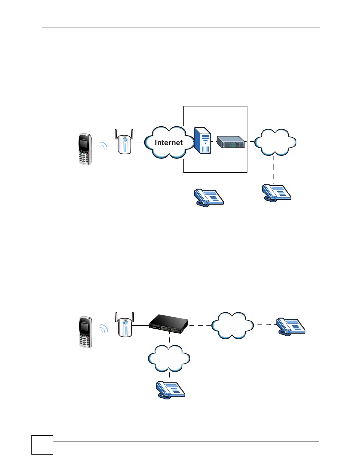
Chapter 1 Introducing the V630
The following figure shows a basic example of how you make a VoIP call through an ITSP. In
this example, you make a call from your V630, which sends the call through your Internet
connection to the ITSP’s SIP server (A). The VoIP call server forwards calls to IP phones (B)
through the Internet. The VoIP call server also forwards calls to PSTN (Public Switched
Telephone Network) phones through a trunking gateway (C) to phones on the PSTN network
(D).
Figure 1 Internet Telephony Service Provider Application
ITSP
A
C
PSTN
D
B
1.2.2 Make Calls via IP-PBX
If your company has an IP-PBX (Internet Protocol Private Branch Exchange), you can use the
V630 to make and receive VoIP telephone calls through it.
In this example, you make a call from your V630, which sends it to the IP-PBX. The IP-PBX
forwards calls to IP phones through an IP network (the IP phones could also be on the
company network or connected to the Internet). The IP-PBX also forwards calls to PSTN
phones.
Figure 2 IP-PBX Application
IP-PBX
PSTN
IP Network
30
V630 User’s Guide
Page 31

1.2.3 Make Peer to Peer Calls
Use the V630 to make a call to the recipient’s IP address wi thou t usi ng a SIP server. Peer-topeer calls are also called “P2P”, “Point to Point”, or “IP-to-IP” calls. You must know the
peer’s IP address in order to do this.
The following figure shows a basic example of how you would make a peer-to-peer VoIP call.
You make a call on your V630, which sends your call through your Internet connection to the
peer VoIP device.
Figure 3 Peer-to-peer Calling
1.3 Ways to Manage the V630
Chapter 1 Introducing the V630
Use any of the following methods to manage the V630.
• Hardware keys. Use the control keys and LCD menus on the V630 for basic configuration.
Refer to the Quick Start Guide for descriptions of the hardware features and how to
perform basic phone functions.
• Web Configurator. Use this to upload firmware to the V630 using a (supported) web
browser.
1.4 Good Habits for Managing the V630
Do the following things regularly to make the V630 more secure and to manage the V630
more effectively.
• Change the web configurator password. Use a password that’s not easy to guess and that
consists of different types of characters, such as numbers and letters.
• Write down the password and put it in a safe place.
• Keep the V630 in a safe place. The LCD menus are not password-protected, so anyone
using the phone can access your phonebook, SIP account information, and so on.
V630 User’s Guide
31
Page 32

Chapter 1 Introducing the V630
32
V630 User’s Guide
Page 33

PART II
LCD Screen Menus
Using the LCD Screen (35)
Call Log LCD Menus (41)
Profiles LCD Menus (43)
General Setup LCD Menus (49)
Network LCD Menus (69)
The Phonebook (99)
Call Options (109)
33
Page 34

34
Page 35

CHAPTER 2
Using the LCD Screen
This chapter shows how to use and configure the V630 via the LCD screen menu system.
" See the Quick Start Guide for a basic introduction to the LCD screen.
2.1 Entering the Menu System
From the V630’s main screen, press the Left key (Menu) to enter the menus. The Main Menu
screen displays as shown below.
Figure 4 Main Menu
-------Main Menu---1 Call log
2 Profiles
3 Setup
4 Network
Select Back
See the following chapters for details on configuring each menu.
2.2 Navigation
Use the following keys to move around the V630’s LCD scre en menu system.
•The Up and Down keys
Use this to move the cursor up and down (when selecting a menu item) or left and right
(when editing a field).
• An asterisk (*) next to a menu item identifies the currently configured option.
•The Left and Right keys
Look at the LCD screen. If there is a word or symbol above a softkey, press the key to
perform the function.
• The alphanumeric keypad
Enter a menu item’s number to jump to that item (single-digit numbers only).
V630 User’s Guide
35
Page 36

Chapter 2 Using the LCD Screen
2.3 Entering Numbers, Letters and Symbols
When you enter information into the V630 (when setting up a phonebook entry, for example)
you may need to enter different kinds of characters. The alphanumeric keypad has these input
modes:
• Lowercase mode
• Uppercase mode
Use the # key to cycle between modes.
" Not all modes are available in all screens.
When you press a key to enter a character, wait a short time until the cursor moves on to the
next space. Press a key multiple times to access the different characters. For example, in
Uppercase mode press 9 four times to enter “Z”.
The following tables show the numbers, letters and symbols you can enter in each mode.
Table 2 Lowercase Mode Keypad Characters
Character Entered for Each Number of Key Presses
12 3 4567 8910111213
KEY
1. , ‘ ?! - & #1 _€
2ab c 2àá â ãäåç
3d e f 3 è é ê ë
4g h i 4 ì í î ï
5j k l 5 £
6mn o 6ñò ó ôõöø
7p q r s 7 ß $
8t u v 8 ù ú û ü
9wx y z 9 ý
** @
00,+space
36
# [CYCLE MODE]
V630 User’s Guide
Page 37

Table 3 Uppercase Mode Keypad Characters
Character Entered for Each Number of Key Presses
12 3 4567 8910111213
KEY
1. , ‘ ?! - & #1_€
2AB C 2ÀÁ Â ÃÄÅÇ
3DE F 3È É Ê Ë
4GH I 4 Ì Í Î Ï
5J K L 5 £
6MN O 6 ÑÒ Ó ÔÕÖØ
7PQ R S7 $
8T U V 8 ÙÚ Û Ü
9WX Y Z 9 ý
** @
00,+space
# [CYCLE MODE]
Chapter 2 Using the LCD Screen
2.4 LCD Menu Overview
This section shows the main LCD menus, and describes what you can do with each.
Table 4 LCD Main Menus Overview
MENU DESCRIPTION
Call Log Missed Calls Use this menu to list the originating numbers of
Received Calls Use this menu to list the originating numbers of
Dialed Calls Use this menu to list the numbers the V630 has
Delete all Use this menu to clear all the records in the call
unanswered calls.
answered calls.
called.
log.
V630 User’s Guide
37
Page 38

Chapter 2 Using the LCD Screen
Table 4 LCD Main Menus Overview (continued)
MENU DESCRIPTION
Profiles Normal Activate Select this phone profile to use regular tone,
Meeting Activate Select this phone profile for more discrete tone,
Outdoor Activate Select this phone profile for louder tone,
Add to Profile Use this menu to create a new profile of tone,
Setup DateTime Set Time/Date Manually set the time and date.
Phone Setting Language Select the menu display language.
Call Setting Forward Use this to configure call forwarding.
Information TCP/IP Check the V630’s IP settings.
volume, and ring settings.
Personalize Use this menu to customize the normal profile’s
tone, volume, and ring settings.
volume, and ring settings.
Personalize Use this menu to customize the meeting
profile’s tone, volume, and ring settings.
volume, and ring settings.
Personalize Use this menu to customize the outdoor profile’s
tone, volume, and ring settings.
volume, and ring settings.
Auto Clock Sync. Set whether or not the V630 gets the time from
an NTP time server. When you enable this,
specify the server’s address.
Set Time Zone Set the V630 to the local time zone.
Phone lock Enable or disable the keypad locking function or
set the keypad lock to turn on automatically if
you do not use the V630 for a specific time.
Backlight Set how long the backlight stays on after you
stop pressing the V630’s keys. You can also set
it to be always on or off.
Quick Button Set the functions of the Up and Down keys in
the main screen.
Web Config Turn web configurator access on or off.
FW Upgrade Upgrade firmware from an HTTP server. Specify
the server’s IP address and port number.
Restore factory Reset the V630 to the factory default settings.
Send Caller ID Set whether or not the V630 sends its phone
number to the callee.
WLAN Check the V630’s wireless LAN settings.
SIP Check the V630’s VoIP settings.
HW Check the V630’s free storage space, firmware,
and MAC address.
Log Check V630’s system events log.
38
V630 User’s Guide
Page 39

Chapter 2 Using the LCD Screen
Table 4 LCD Main Menus Overview (continued)
MENU DESCRIPTION
Network Site scan Looks for available Access Points (APs).
WLAN Profiles Profiles List Look thr ough and edit already configured
Add to Profile Create a profile of WLAN settings.
WPS Connect to a WPS-enabled AP.
SIP Profiles Profiles List Look through and edit already configured
Add to Profile Create a profile of SIP settings.
Ping test Manual Specify an IP address to which to send a ping.
Gateway Send a ping to the gateway IP address.
DNS Send a ping to the DNS server IP address.
SIP Server Send a ping to the SIP server.
SIP Proxy Send a ping to the SIP proxy server.
Outbound Proxy Send a ping to the SIP outbound proxy server.
Stun Server Send a ping to the STUN server.
Re-connect Have the V630 attempt to connect to the WLAN.
profiles of WLAN settings.
profiles of SIP settings.
V630 User’s Guide
39
Page 40

Chapter 2 Using the LCD Screen
This section describes the phonebook LCD menus which you access by pressing the Right key
from the main screen.
Table 5 LCD Phonebook Menus Overview
MENU DESCRIPTION
Phonebook Talk Call the selected contact.
Detail Display the information configured for the
Edit Use this to modify the information configured for
Delete Remove the selected contact.
Add Create a new contact entry.
Group None Select this to not add the contact to any group.
Speed Dial Set up one-touch calling for phone numbers you
Delete All Remove all phone book entries.
Memory Status This shows how many more phone book entries
selected contact.
the selected contact.
Business Add members to this group and specify the ring
tone for incoming calls coming from them.
Family Add members to this group and specify the ring
tone for incoming calls coming from them.
Friends Add members to this group and specify the ring
tone for incoming calls coming from them.
VIP Add members to this group and specify the ring
tone for incoming calls coming from them.
Other Add members to this group and specify the ring
tone for incoming calls coming from them.
call often.
the V630 can store.
40
V630 User’s Guide
Page 41

CHAPTER 3
Call Log LCD Menus
This chapter discusses the V630’s Call Log LCD menus.
3.1 Call Log
The Call Log menu allows you to quickly check the numbers of the most recent missed,
received, or dialed calls. Press Menu > Call Log to display the following screen.
Figure 5 Menu > Call log
-------Call log---1 Missed Calls
2 Received Calls
3 Dialed Calls
4 Delete all
Select Back
The following table describes the labels in this screen.
Table 6 Menu > Call log
LABEL DESCRIPTION
Missed Calls Use this menu to list the originating numbers of unanswered calls.
Received Calls Use this menu to list the originating numbers of answered calls.
Dialed Calls Use this menu to list the numbers the V630 has called.
Delete all Use this menu to clear all the records in the call log.
Select Press this to choose the highligh te d field in the menu.
Back Press this to return to the previous screen.
3.2 Received Calls
The Received Calls menu allows you to quickly check the numbers of the most recent
received calls. Press Menu > Call Log > Received Calls to display the following screen. The
missed calls and dialed calls lists work in the same manner.
V630 User’s Guide
41
Page 42

Chapter 3 Call Log LCD Menus
Figure 6 Menu > Call log > Received Calls
---Received calls--1 Tom
2 Bill
3 Jim
Select Back
The following table describes the labels in this screen.
Table 7 Menu > Call log > Received Calls
LABEL DESCRIPTION
Received Calls Select an entry to see the time and date of the call.
Select Press this to choose the highligh te d field in the menu.
Back Press this to return to the previous screen.
42
V630 User’s Guide
Page 43

CHAPTER 4
Profiles LCD Menus
This chapter discusses the V630’s Profiles LCD menus.
4.1 Profiles Setup
Use the Profiles menu to select or modify a profile of tone, volume, and ring settings. Press
Menu > Profiles to display the following screen.
Figure 7 Menu > Profiles
---Profiles Setup--1 *Normal
2 Meeting
3 Outdoor
4 Add to Profile
Select Back
The following table describes the labels in this screen.
Table 8 Menu > Profiles
LABEL DESCRIPTION
Normal Use this menu to turn on the normal profile and/or configure the normal profile’s
Meeting The meeting profile provides more discrete tone, volume, and ring settings. Use this
Outdoor The outdoors profile has louder tone, volume, and ring settings. Use this menu to
Add to Profile Use this menu to create a new profile of tone, volume, and ring settings.
Select Press this to choose the highlighted field in the menu.
Back Press this to return to the previous screen.
tone, volume, and ring settings.
menu to turn on the meeting profile and/or configure the meeting profile’s tone,
volume, and ring settings.
turn on the outdoors profile and/or configure the outdoors profile’s tone, volume, and
ring settings.
4.2 Phone Profile Options
Press Menu > Profiles to display the profiles. Select a profile to open the following menu. A
user-added profile named TEST is shown in this example). You can turn on the profile or
configure its settings. You can also rename or delete a user-added profile.
V630 User’s Guide
43
Page 44

Chapter 4 Profiles LCD Menus
Figure 8 Menu > Profiles > Profile
--------TEST------1 Activate
2 Personalize
3 Rename
4 Delete
Select Back
The following table describes the labels in this screen.
Table 9 Menu > Profiles > Profile
LABEL DESCRIPTION
Activate Select this to have the V630 use the profile’s tone, volume, and ring settings.
Personalize Select this to configure the profile’s tone, volume, and ring settings.
Rename Select this to change the name of the profile. This option only appears for profiles
Delete Select this to remove the profile. This option only appears for profiles that you add.
Select Press this to choose the highlighted field in the menu.
Back Press this to return to the previous screen.
Note: There is also a quick button shortcut. Hold down the * key to
switch between the current profile and the meeting profile.
that you add. It does not appear with the default profiles.
It does not appear with the default profiles.
4.3 Phone Profile Personalization
Press Menu > Profiles to display the profiles. Select a profile (Meeting in this example) and
then select Personalize to open the following menu. Select whether you want to edit the
profile’s tone, volume, or ring settings.
Figure 9 Menu > Profiles > Profile > Personalize
-------Meeting-----1 Tone setting
2 Volume
3 Ring mode
Select Back
The following table describes the labels in this screen.
Table 10 Menu > Profiles > Profile > Personalize
LABEL DESCRIPTION
Tone setting Select this to configure the profile’s ring and/or key tone settings.
Volume Select this to configure the profile’s ring, receiver, speaker, and/or key tone volume
settings.
Ring mode Select this to set the profile to have the V630 ring, vibrate, ring and vibrate, or
vibrate and then ring for incoming calls.
44
V630 User’s Guide
Page 45

Table 10 Menu > Profiles > Profile > Personalize
LABEL DESCRIPTION
Select Press this to choose the highlighted field in the menu.
Back Press this to return to the previous screen.
4.4 Tone Personalization
Press Menu > Profiles to display the profiles. Select a profile (Meeting in this example) and
then select Personalize > Tone setting to open the following menu. Select whether you want
to edit the profile’s ring tone or key tone settings.
Figure 10 Menu > Profiles > Profile > Personalize > Tone Setting
-------Meeting-----1 Ring tones
2 Key tone
Chapter 4 Profiles LCD Menus
Select Back
The following table describes the labels in this screen.
Table 11 Menu > Profiles > Profile > Personalize > Tone Setting
LABEL DESCRIPTION
Ring tones Select this to chose the ring tone for incoming calls.
Key tone Select this to turn the key tone (sounds when you press the keys) on or off.
Select Press this to choose the highlighted field in the menu.
Back Press this to return to the previous screen.
4.5 Ring Tone Personalization
Press Menu > Profiles to display the profiles. Select a profile (Meeting in this example) and
then select Personalize > Tone setting > Ring tones to open the following menu. Use this to
select the profile’s ring tone.
Figure 11 Menu > Profiles > Profile > Personalize > Tone Setting > Ring tones
----Select Melody--1 Allegro
2 Bach
3 Beethoven 5th
4 Birthday
Select Back
V630 User’s Guide
45
Page 46

Chapter 4 Profiles LCD Menus
The following table describes the labels in this screen.
Table 12 Menu > Profiles > Profile > Personalize > Tone Setting > Ring tones
LABEL DESCRIPTION
Select Melody Select the ring tone for incoming calls. Leave the cursor on a ring tone for a
Select Press this to choose the highlighted field in the menu.
Back Press this to return to the previous screen.
preview of the tone. The V630’s current phone profile must be set to use an
audible ring for incoming calls in order for you to here the preview.
4.6 Volume Personalization
Press Menu > Profiles to display the profiles. Select a profile (Meeting in this example) and
then select Personalize > Volume to open the following menu. You can modify the profile’s
ring, receiver, speaker, and/or key tone volume settings.
Figure 12 Menu > Profiles > Profile > Personalize > Volume
-------Volume-----1 Ring Vol.
2 Receiver Vol.
3 Speaker Vol.
4 Key tone Vol.
Select Back
The following table describes the labels in this screen.
Table 13 Menu > Profiles > Profile > Personalize > Volume
LABEL DESCRIPTION
Ring Vol. Select this to set how loud the ring tone for incoming calls is.
Receiver Vol. Select this to set how loud your voice sounds to the person you are talking to.
Speaker Vol. Select this to set the volume of the V630’s speaker (how loud the voice of the
person you are talking to sounds).
Key tone Vol. Select this to set the key tone volume (how load the sounds are when you press the
Select Press this to choose the highlighted field in the menu.
Back Press this to return to the previous screen.
keys).
4.7 Ring Volume Personalization
Press Menu > Profiles to display the profiles. Select a profile (Meeting in this example) and
then select Personalize > Volume. When you select an option in the Volume menu, a screen
similar to the following displays. This example uses the Ring Vol. screen.
46
V630 User’s Guide
Page 47

Figure 13 Menu > Profiles > Profile > Personalize > Volume > Ring Vol.
------Ring Vol.-----
Select Back
The following table describes the labels in this screen.
Table 14 Menu > Profiles > Profile > Personalize > Volume > Ring Vol.
LABEL DESCRIPTION
Ring Vol. The bar in the screen displays the volume setting. Use the numbers on the keypad
to set the volume higher or lower.
Back Press this to return to the previous screen.
4.8 Ring Mode Personalization
Chapter 4 Profiles LCD Menus
Press Menu > Profiles to display the profiles. Select a profile (Meeting in this example) and
then select Personalize > Ring Mode to open the following menu. You can set the profile to
have the V630 ring, vibrate, ring and vibrate, or vibrate and then ring for incoming calls.
Figure 14 Menu > Profiles > Profile > Personalize > Ring Mode
------Ring Mode----1 Ring only
2 Vibrate
3 Ring and Vib.
4 Vib, then R..
Select Back
The following table describes the labels in this screen.
Table 15 Menu > Profiles > Profile > Personalize > Ring Mode
LABEL DESCRIPTION
Ring only Select this to have the phone only ring for incoming calls (not vibrate).
Vibrate Select this to have the phone only vibrate for incoming calls (not ring).
Ring and Vib. Select this to have the phone ring and vibrate for incoming calls.
Vib, then Ring Select this to have the phone vibrate first for an incoming call and then ring if you
haven’t answered it yet.
Select Press this to choose the highlighted field in the menu.
Back Press this to return to the previous screen.
V630 User’s Guide
47
Page 48

Chapter 4 Profiles LCD Menus
4.9 Adding a Phone Profile
Press Menu > Profiles to display the profiles. Select Add to Profile to open the following
menu. Use this menu to configure the name of the new profile. Then you can use the menus to
configure the profile in the same way that you configure an existing profile.
Figure 15 Menu > Profiles > Add to Profile
----Add to Profile--
Done ABC Back
The following table describes the labels in this screen.
Table 16 Menu > Profiles > Add to Profile
LABEL DESCRIPTION
Input the name of the profile. When you press a key, other character options appear
above the input field. Press a key multiple times to input one of the characters
above.
Done Press this to save your setting.
ABC Press # to switch between the lower-case and upper-case input modes.
Back Press this to return to the previous screen.
Clear After you start inputting text, Back changes to Clear. Press this to backspace.
48
V630 User’s Guide
Page 49

CHAPTER 5
General Setup LCD Menus
This chapter discusses the V630’s Setup LCD menus.
5.1 General Setup
Use the Setup menu to configure the V630’s general settings and display various types of
status information. Press Menu > Setup to display the following screen.
Figure 16 Menu > Setup
-------Setup------1 DateTime
2 Phone Setting
3 Call Setting
4 Information
Select Back
The following table describes the labels in this screen.
Table 17 Menu > Setup
LABEL DESCRIPTION
DateTime Select this to configure the V630’s time and date settings.
Phone Setting Select this to configure the V630’s general phone settings such as the display
language, keypad lock, backlight, quick access buttons, and web configurator
access. You can also upgrade the V630’s firmware or reset the V630 to the factory
default settings.
Call Setting Select this to configure call forwarding and whether or not the V630 sends its phone
number to the callee.
Information Select this to check the V630’s IP, wireless LAN, and VoIP settings. You can also
display the V630’s free storage space, firmware, MAC address, and system events
log.
Select Press this to choose the highlighted field in the menu.
Back Press this to return to the previous screen.
5.2 Date and Time Setup
Press Menu > Setup > DateTime to display the following screen. Use this menu to select
what time and date settings you want to configure.
V630 User’s Guide
49
Page 50

Chapter 5 General Setup LCD Menus
Figure 17 Menu > Setup > DateTime
----Set Time/Date--1 Set Time/Date
2 Auto Clock Syn
3 Set Time Zone
Select Back
The following table describes the labels in this screen.
Table 18 Menu > Setup > DateTime
LABEL DESCRIPTION
Set Time/Date Select this to manually set the time and date.
Auto Clock
Sync.
Set Time Zone Select this to set the V630 to the local time zone.
Select Press this to choose the highlighted field in the menu.
Back Press this to return to the previous screen.
Select this to set whether or not the V630 gets the time from an NTP time server.
When you enable this, specify the server’s address.
5.3 Manual Date or Time Setup
Press Menu > Setup > DateTime > Set Time/Date to display the following screen. Use this
menu to select whether to want to manually set the time or the date.
Figure 18 Menu > Setup > DateTime > Set Time/Date
----Set Time/Date--1 Time
2 Date
Select Back
The following table describes the labels in this screen.
Table 19 Menu > Setup > DateTime > Set Time/Date
LABEL DESCRIPTION
Time Select this to manually set the time.
Date Select this to manually set the date.
Select Press this to choose the highlighted field in the menu.
Back Press this to return to the previous screen.
50
V630 User’s Guide
Page 51

5.4 Manual Time Setup
Press Menu > Setup > DateTime > Set Time/Date > Time to display the following screen.
Use this menu to select whether to manually set the time.
Figure 19 Menu > Setup > DateTime > Set Time/Date > Time
---------Time------24 hour time
:30
0
Set Back
The following table describes the labels in this screen.
Table 20 Menu > Setup > DateTime > Set Time/Date > Time
LABEL DESCRIPTION
24 hour time Use the numbers on the keypad to set the hour (in 24-hour format) and then the
Set Press this to enter your setting.
Back Press this to return to the previous screen.
minute. Use the Up and Down keys if you need to move the cursor.
Chapter 5 General Setup LCD Menus
5.5 Manual Date Setup
Press Menu > Setup > DateTime > Set Time/Date > Date to display the following screen.
Use this menu to select whether to manually set the date.
Figure 20 Menu > Setup > DateTime > Set Time/Date > Date
---------Date------Month/Day/Year
1
/1/2000
Set Back
The following table describes the labels in this screen.
Table 21 Menu > Setup > DateTime > Set Time/Date > Date
LABEL DESCRIPTION
Month/Day/Year Use the numbers on the keypad to set the month, day, and year. Use the Up and
Down keys if you need to move the cursor.
Set Press this to enter your setting.
Back Press this to return to the previous screen.
V630 User’s Guide
51
Page 52

Chapter 5 General Setup LCD Menus
5.6 Using a Time Server
Press Menu > Setup > DateTime > Auto Clock Syn to display the following screen. Use this
menu to set whether or not the V630 uses a time server.
" The V630 has to be able to connect to the Internet to actually get the time and
date from a time server.
Figure 21 Menu > Setup > DateTime > Auto Clock Syn
---Auto clock set--1 Enable
2 Disable
Select Back
The following table describes the labels in this screen.
Table 22 Menu > Setup > DateTime > Auto Clock Syn
LABEL DESCRIPTION
Enable Select this to have the V630 attempt to get the time from an NTP time server.
Date Select this to stop the V630 from attempting to get the time from an NTP time
server.
Select Press this to choose the highlighted field in the menu.
Back Press this to return to the previous screen.
5.7 Specifying a Time Server
Press Menu > Setup > DateTime > Auto Clock Syn > Enable to display the following
screen. Use this menu to specify a time server for the V630 to use.
Figure 22 Menu > Setup > DateTime > Auto Clock Syn > Enable
-----NTP Server-----
52
Done ABC Back
V630 User’s Guide
Page 53

The following table describes the labels in this screen.
Table 23 Menu > Setup > DateTime > Auto Clock Syn > Enable
LABEL DESCRIPTION
NTP Server Input the IP address or URL of the NTP time server. When you press a key, other
character options appear above the input field. Press a key multiple times to input
one of the characters above.
Done Press this to save your setting.
ABC Press # to switch between the lower-case and upper-case input modes.
Back Press this to return to the previous screen.
Clear After you start inputting text, Back changes to Clear. Press this to backspace.
5.8 Time Zone Setup
Press Menu > Setup > DateTime > Set Time Zone to display the following screen. Use this
menu to set the V630 to use the local time zone.
Figure 23 Menu > Setup > DateTime > Time Zone
-------TimeZone----Greenwich
Mean Time:
London
Chapter 5 General Setup LCD Menus
GMT0
Select Back
The following table describes the labels in this screen.
Table 24 Menu > Setup > DateTime > Time Zone
LABEL DESCRIPTION
Time Zone Use the Up or Down to your local time zone.
GMT0 This shows how many hours the time zone is ahead of or behind GMT (Greenwich
Mean Time).
Select Press this to choose the highlighted field in the menu.
Back Press this to return to the previous screen.
5.9 General Phone Setup
Press Menu > Setup > Phone Setting to display the following screen. Use this menu to select
which of the V630’s general phone settings to configure. You can set the display language,
keypad lock, backlight, quick access buttons, and web configurator access. You can also
upgrade the V630’s firmware or reset the V630 to the factory default settings.
V630 User’s Guide
53
Page 54

Chapter 5 General Setup LCD Menus
Figure 24 Menu > Setup > Phone Setting
----Phone Setting--1 Language
2 Phone Lock
3 Backlight
4 Quick Button
Select Back
The following table describes the labels in this screen.
Table 25 Menu > Setup > Phone Setting
LABEL DESCRIPTION
Language Select the menu display language.
Phone lock Enable or disable the automatic keypad locking function or set the keypad lock to
turn on automatically if you do not use the V630 for a specific time.
Backlight Set how long the backlight stays on after you stop pressing the V630’s keys. You
can also set it to be always on or off.
Quick Button Set the functions of the Up and Down keys in the main screen.
Web Config Turn web configurator access on or off.
FW Upgrade Upgrade firmware from an HTTP server. Specify the server’s IP address and port
number.
Restore factory Reset the V630 to the factory default settings.
Select Press this to choose the highlighted field in the menu.
Back Press this to return to the previous screen.
5.10 Language Setup
Press Menu > Setup > Phone Setting > Language to display the following screen. Use this
menu to select the V630’s display language.
Figure 25 Menu > Setup > Phone Setting > Language
-------Language----1 English
Select Back
The following table describes the labels in this screen.
Table 26 Menu > Setup > Phone Setting > Language
LABEL DESCRIPTION
Language Select the menu display language.
1. Only English is supported at the time of writing.
1
54
V630 User’s Guide
Page 55

Chapter 5 General Setup LCD Menus
Table 26 Menu > Setup > Phone Setting > Language
LABEL DESCRIPTION
Select Press this to choose the highlighted field in the menu.
Back Press this to return to the previous screen.
5.11 Keypad Lock Setup
Press Menu > Setup > Phone Setting > Phone lock to display the following screen. The
V630’s keypad lock helps prevent accidental calls. Use this menu to set the V630’ s automatic
keypad lock.
" Regardless of the setting in this menu, you can still press the Left key and *
from the main screen to lock or unlock the V630’s keypad.
Figure 26 Menu > Setup > Phone Setting > Phone lock
------Phone lock---1 *OFF
2 15s
3 30s
4 60s
Select Back
The following table describes the labels in this screen.
Table 27 Menu > Setup > Phone Setting > Phone lock
LABEL DESCRIPTION
Phone lock Select OFF to turn off the automatic keypad lock function (to always leave the
keypad unlocked).
Or select the number of idle seconds after which the V630 automatically locks the
keypad. For example, select 30s to have the V630 lock the keypad after you stop
using the V630 for longer than 30 seconds.
Select Press this to choose the highlighted field in the menu.
Back Press this to return to the previous screen.
5.12 Backlight Setup
Press Menu > Setup > Phone Setting > Backlight to display the following screen. Use this
menu to set how long the V630’s backlight stays on.
V630 User’s Guide
55
Page 56

Chapter 5 General Setup LCD Menus
Figure 27 Menu > Setup > Phone Setting > Backlight
------Backlight---1 OFF
2 4s
3 7s
4 *10s
Select Back
The following table describes the labels in this screen.
Table 28 Menu > Setup > Phone Setting > Backlight
LABEL DESCRIPTION
Phone lock Select OFF to turn off the backlight all the time.
Or select the number of idle seconds after which the V630 automatically turns off the
backlight. For example, select 10s to have the V630 turn off the backlight 10
seconds after you stop pressing the keys.
Select Press this to choose the highlighted field in the menu.
Back Press this to return to the previous screen.
5.13 Quick Button Setup
Press Menu > Setup > Phone Setting > Quick button to display the following screen. Use
this menu to select which quick access button you want to configure.
Figure 28 Menu > Setup > Phone Setting > Quick button
-----Quick button--1 Up Button
2 Down Button
Select Back
The following table describes the labels in this screen.
Table 29 Menu > Setup > Phone Setting > Quick button
LABEL DESCRIPTION
Up Button Select this to configure the function of the Up key in the main screen.
Down Button Select this to configure the function of the Down key in the main screen.
Select Press this to choose the highlighted field in the menu.
Back Press this to return to the previous screen.
56
V630 User’s Guide
Page 57

5.14 Up Quick Button Setup
Press Menu > Setup > Phone Setting > Quick button > Up Button to display the following
screen. Use this menu to configure the function of the Up key in the main screen. The
configuration for the Down key works in the same manner.
Figure 29 Menu > Setup > Phone Setting > Quick button > Up Button
-----Quick button--1 Information
2 Speaker Volume
3 Receiver Vol..
4 Profiles
Select Back
The following table describes the labels in this screen.
Table 30 Menu > Setup > Phone Setting > Quick button > Up Button
LABEL DESCRIPTION
Information
Speaker Volume Select this to open the talking volume setting when you press the Up key in the main
screen.
Receiver
Volume
Profiles Select this to be able to select or configure phone profiles when you press the Up
Select Press this to choose the highlighted field in the menu.
Back Press this to return to the previous screen.
Select this to open the listening volume setting when you press the Up key in the
main screen.
key in the main screen.
Chapter 5 General Setup LCD Menus
5.15 Enabling or Disabling the Web Configurator
Press Menu > Setup > Phone Setting > Web Config to display the following screen. Use this
menu to turn web configurator access on or off.
Figure 30 Menu > Setup > Phone Setting > Web Config
------Web Config---1 *OFF
2 On
Select Back
V630 User’s Guide
57
Page 58

Chapter 5 General Setup LCD Menus
The following table describes the labels in this screen.
Table 31 Menu > Setup > Phone Setting > Web Config
LABEL DESCRIPTION
OFF Select this to not allow access to the web configurator.
ON Select this to allow access to the web configurator.
Note: Allowing access to the web configurator reduces
battery life.
Select Press this to choose the highlighted field in the menu.
Back Press this to return to the previous screen.
5.16 Firmware Upgrade from an HTTP Server
Press Menu > Setup > Phone Setting > FW Upgrade to display the following screen. Use
this menu to select whether you want to upgrade firmware from an HTTP server, specify the
server’s address, or specify the server’s port number.
" Your network administrator or service provider must have an HTTP server set
up with the firmware file in order for you to use this.
Figure 31 Menu > Setup > Phone Setting > FW Upgrade
------FW Upgrade---1 Upgrade Now
2 Server Address
3 Server Port
Select Back
The following table describes the labels in this screen.
Table 32 Menu > Setup > Phone Setting > FW Upgrade
LABEL DESCRIPTION
Upgrade Now Select this to upload new firmware from the HTTP server. You need to have the
server’s address and port number configured already to be able to use this.
Server Address Select this to go to a menu where you can enter the address of the HTT P server.
Server Port Select this to go to a menu where you can enter the port number of the HTTP
server. You need to do this if the HTTP server with the firmware is not using the
standard port number (80).
Select Press this to choose the highlighted field in the menu.
Back Press this to return to the previous screen.
58
V630 User’s Guide
Page 59

Chapter 5 General Setup LCD Menus
5.17 HTTP Firmware Upgrade Server Address
Press Menu > Setup > Phone Setting > FW Upgrade > Server Address to display the
following screen. Use this menu to specify the server’s address. The port configuration menu
works in a similar manner, except you can only input numbers.
Figure 32 Menu > Setup > Phone Setting > FW Upgrade > Server Address
---Server Address---
Done ABC Back
The following table describes the labels in this screen.
Table 33 Menu > Setup > Phone Setting > FW Upgrade > Server Address
LABEL DESCRIPTION
Server Address Input the IP address or URL of the HTTP server with the firmware file. When you
press a key, other character options appear above the input field. Press a key
multiple times to input one of the characters above.
Done Press this to save your setting.
ABC Press # to switch between the lower-case and upper-case input modes.
Back Press this to return to the previous screen.
Clear After you start inputting text, Back changes to Clear. Press this to backspace.
5.18 Restore Factory Default Settings
Press Menu > Setup > Phone Setting > Restore Factory to display the following screen. Use
this menu to reset the V630 to the factory default settings.
" Restoring the factory default settings resets all of the phone’s settings except
your phone book entries.
Figure 33 Menu > Setup > Phone Setting > Restore Factory
---Restore Factory-Are you sure,
reset to
default?
Yes Cancel
V630 User’s Guide
59
Page 60

Chapter 5 General Setup LCD Menus
The following table describes the labels in this screen.
Table 34 Menu > Setup > Phone Setting > Restore Factory
LABEL DESCRIPTION
Yes Select this to reset the V630 to the factory default settings.
Cancel Select this to return to the previous screen without resetting the V630 to the factory
default settings.
5.19 Call Settings
Press Menu > Setup > Call Setting to display the following screen. Use this menu to go to
menus where you can configure call forwarding or whether or not the V630 sends its phone
number to the callee.
Figure 34 Menu > Setup > Call Setting
-----Call Setting--1 Forward
2 Send Caller ID
Select Back
The following table describes the labels in this screen.
Table 35 Menu > Setup > Call Setting
LABEL DESCRIPTION
Forward Use this to configure call forwarding.
Send Caller ID Set whether or not the V630 sends its phone number to the callee.
Select Press this to choose the highlighted field in the menu.
Back Press this to return to the previous screen.
5.20 Call Forwarding
Press Menu > Setup > Call Setting > Forward to display the following screen. Use this
menu to turn call forwarding on or off.
Figure 35 Menu > Setup > Call Setting > Forward
--------Forward----1 *OFF
2 ON
60
Select Back
V630 User’s Guide
Page 61

The following table describes the labels in this screen.
Table 36 Menu > Setup > Call Setting > Forward
LABEL DESCRIPTION
OFF Select this to not forward calls.
ON Select this to forward calls.
Select Press this to choose the highlighted field in the menu.
Back Press this to return to the previous screen.
5.21 Call Forwarding Number
Press Menu > Setup > Call Setting > Forward > ON to display the following screen. Use
this menu to input the phone number to which you want to forward calls.
Figure 36 Menu > Setup > Call Setting > Forward > ON
----Forward Number--
Chapter 5 General Setup LCD Menus
Done Back
The following table describes the labels in this screen.
Table 37 Menu > Setup > Call Setting > Forward > ON
LABEL DESCRIPTION
Forward
Number
Done Press this to save your setting.
Back Press this to return to the previous screen.
Clear After you start inputting text, Back changes to Clear. Press this to backspace.
Use the number keys to input the phone number to which you want to forward calls.
5.22 Call Forwarding Type
Press Menu > Setup > Call Setting > Forward > ON and input a phone number to display
the following screen. Use this menu to set under what circumstances you want to apply call
forwarding.
V630 User’s Guide
61
Page 62

Chapter 5 General Setup LCD Menus
Figure 37 Menu > Setup > Call Setting > Forward > ON > Number
-----Forward Type--1 *Always
2 Busy
3 No Answer
4 Busy & No An..
Select Back
The following table describes the labels in this screen.
Table 38 Menu > Setup > Call Setting > Forward > ON > Number
LABEL DESCRIPTION
Always Select this to forward all calls to the specified number (regardless of whether or not
your line is busy).
Busy Select this to forward calls when your line is busy.
No Answer Select this to forward calls when you do not answer the phone. You will be able to
specify how long the V630 waits before forwarding an unanswered call.
Busy & No
Answer
Select Press this to choose the highlighted field in the menu.
Back Press this to return to the previous screen.
Select this to forward calls when your line is busy or you do not answer the phone.
You will be able to specify how long the V630 waits before forwarding an
unanswered call.
5.23 Call Forwarding No Answer Time
When you set the call forwarding type to No Answer or Busy & No Answer, use this menu to
specify how long the V630 waits before forwarding an unanswered call.
Figure 38 Menu > Setup > Call Setting > Forward > ON > Number > Type > No Answer
----NoAnswer Time--1 5s
2 10s
3 15s
4 20s
Select Back
The following table describes the labels in this screen.
Table 39 Menu > Setup > Call Setting > Forward > ON > Number > T ype > No Answer
LABEL DESCRIPTION
NoAnswer Time Specify how long the V630 waits before forwarding an unanswered call. You can
use one of the pre-defined settings (5, 10, 15 or 20 seconds) or select Other to
manually configure another time period.
Busy Select this to forward calls when your line is busy.
Select Press this to choose the highlighted field in the menu.
Back Press this to return to the previous screen.
62
V630 User’s Guide
Page 63

5.24 Call Forwarding No Answer Time
When you set the call forwarding type to No Answer or Busy & No Answer and select Other
as the no answer time, use this menu to specify a custom time period for how long the V630
waits before forwarding an unanswered call.
Figure 39 Menu > Setup > Call Setting > Forward > ON > Number > Type > No Answer >
Other
Enter NoAnser Secs
Done Back
The following table describes the labels in this screen.
Table 40 Menu > Setup > Call Setting > Forward > ON > Number > Type > No Answer >
Other
LABEL DESCRIPTION
Enter NoAnser
Secs
Done Press this to save your setting.
Back Press this to return to the previous screen.
Clear After you start inputting text, Back changes to Clear. Press this to backspace.
Use the number keys to input the number of seconds the V630 waits before
forwarding an unanswered call
Chapter 5 General Setup LCD Menus
5.25 Send Caller ID
Press Menu > Setup > Call Setting > Send Caller ID to display the following screen. Use
this menu to set whether or not the V630 sends your phone number to the phones you call.
Figure 40 Menu > Setup > Call Setting > Send Caller ID
---Send Caller Id--1 OFF
2 *ON
Select Back
The following table describes the labels in this screen.
Table 41 Menu > Setup > Call Setting> Send Caller ID
LABEL DESCRIPTION
OFF Select this to have the V630 not send your phone number to the phones you call.
ON Select this to have the V630 send y our phone number to the phones you call.
V630 User’s Guide
63
Page 64

Chapter 5 General Setup LCD Menus
Table 41 Menu > Setup > Call Setting> Send Caller ID
LABEL DESCRIPTION
Select Press this to choose the highlighted field in the menu.
Back Press this to return to the previous screen.
5.26 Information
Press Menu > Setup > Information to display the following screen. Use this menu to go to
menus where you can check the V630’s IP, wireless LAN, and VoIP settings. You can also
display the V630’s free storage space, firmware, MAC address, and system events log.
Figure 41 Menu > Setup > Information
-----Information---1 TCP/IP
2 WLAN
3 SIP
4 HW
Select Back
The following table describes the labels in this screen.
Table 42 Menu > Setup > Information
LABEL DESCRIPTION
TCP/IP Select this to check the V630’s IP settings.
WLAN Select this to check the V630’s wireless LAN settings.
SIP Select this to check the V630’s VoIP settings.
HW Select this to check the V630’s free storage space, firmware, and MAC address.
Log Select this to check the V630’s system events log.
Select Press this to choose the highlighted field in the menu.
Back Press this to return to the previous screen.
5.27 TCP/IP Information
Press Menu > Setup > Information > TCP/IP to display the following screen. Use this menu
to check the V630’s IP address, subnet mask, default gateway IP address, and DNS server IP
address. The IP address displays first. Use the Down key to scroll in order to display the other
settings.
" “Network Not Up Yet!” displays if the V630 has not connected to an AP yet.
64
V630 User’s Guide
Page 65

Chapter 5 General Setup LCD Menus
Figure 42 Menu > Setup > Information > TCP/IP
--------TCP/IP-----IP Address
192.168.1.34
Back
The following table describes the labels in this screen.
Table 43 Menu > Setup > Information > TCP/IP
LABEL DESCRIPTION
IP Address This is the IP address currently assigned to the V630.
IP Subnet Mask This is the subnet mask currently configured on the V630.
Gateway This is the IP address of the device on the network that your V630 uses to access
DNS This is the DNS (Domain Name System) server your V630 uses.
Back Press this to return to the previous screen.
other networks (like the Internet).
5.28 WLAN Information
Press Menu > Setup > Information > WLAN to display the following screen. Use this menu
to check the V630’s wireless LAN settings. The SSID displays first. Use the Down key to
scroll in order to display the other settings.
Figure 43 Menu > Setup > Information > WLAN
--------WLAN-------SSID
WLAN_example
Back
The following table describes the labels in this screen.
Table 44 Menu > Setup > Information > WLAN
LABEL DESCRIPTION
SSID This is the SSID that the V630 is currently using.
BSSID This is the V630’s MAC (Media Access Control) address. Every network device has
Channel This is the radio frequency that the V630 is currently using.
Security This is the type of wireless security that the V630 is currently using. The V630
Back Press this to return to the previous screen.
a unique MAC address that identifies it across the network.
supports WEP, WPA PSK, WPA2 PSK, WPA, and WPA2.
V630 User’s Guide
65
Page 66

Chapter 5 General Setup LCD Menus
5.29 SIP Information
Press Menu > Setup > Information > SIP to display the following screen. Use this menu to
check the settings for the SIP account the V630 is currently using. The phone number displays
first. Use the Down key to scroll in order to display the other settings.
Figure 44 Menu > Setup > Information > SIP
---------SIP-------Phone Number
123456789
Back
The following table describes the labels in this screen.
Table 45 Menu > Setup > Information > SIP
LABEL DESCRIPTION
Phone Number Thi s is the SIP accou nt’s phone number.
SIP Server This is the address of the SIP server for the SIP account.
SIP Proxy This is the address of the SIP proxy server for the SIP account.
Outbound Proxy This is the address of the outbound proxy server for the SIP account.
Stun Server This is the address of the STUN server for the SIP account.
Expire This is the SIP server expire time.
Back Press this to return to the previous screen.
5.30 Hardware Information
Press Menu > Setup > Information > HW to display the following screen. Use this menu to
check details about the V630’s hardware. The available storage space displays first. Use the
Down key to scroll in order to display the other settings.
Figure 45 Menu > Setup > Information > HW
----------HW-------Storage Free
98% free
Free: 807.572 KB
Total: 823.752 KB
Back
The following table describes the labels in this screen.
Table 46 Menu > Setup > Information > HW
LABEL DESCRIPTION
Storage Free This shows how much of the V630’s storage space is available.
FW Version This is the firmware (embedded software) version and creation date.
66
V630 User’s Guide
Page 67

Table 46 Menu > Setup > Information > HW
LABEL DESCRIPTION
Mac Address This is the V630’s M AC ( Media A ccess Control) address. Every network device has
a unique MAC address that identifies it across the network.
Back Press this to return to the previous screen.
5.31 Log Information
Press Menu > Setup > Information > Log to display the following screen. Use this menu to
check the V630’s system events log. Use the Down key to scroll through the log entries.
Figure 46 Menu > Setup > Information > Log
---------Log-------<1> 10:12:57
BSS_DISCONNEC
TED
Chapter 5 General Setup LCD Menus
Back
The following table describes the labels in this screen.
Table 47 Menu > Setup > Information > Log
LABEL DESCRIPTION
<1> This is the log entry’s index number.
Time This is the time that the log was created (in hour:minute:second format).
Message This is the reason for the log.
Back Press this to return to the previous screen.
V630 User’s Guide
67
Page 68

Chapter 5 General Setup LCD Menus
68
V630 User’s Guide
Page 69

CHAPTER 6
Network LCD Menus
This chapter discusses the V630’s Network LCD menus.
6.1 Network Setup
Use the Network menu to select or modify a profile of tone, volume, and ring settings. Press
Menu > Network to display the following screen.
Figure 47 Menu > Network
--------Network----1 Site scan
2 WLAN Profiles
3 SIP Profiles
4 Ping test
Select Back
The following table describes the labels in this screen.
Table 48 Menu > Network
LABEL DESCRIPTION
Site scan Use this menu to have the V630 check for available Access Points (APs).
WLAN Profiles Use these menus to edit configured profiles of WLAN settings, add new profiles of
SIP Profiles Use these menus to add and edit profiles of SIP settings.
Ping test Use this menu to have the V630 send a ping to an IP address to check the network
Re-connect Use this menu to have the V630 attempt to connect to the WLAN.
Select Press this to choose the highlighted field in the menu.
Back Press this to return to the previous screen.
6.2 Site Scan
Press Menu > Network > Site scan to have the V630 check for available APs. After the V630
finishes scanning, use the Down key to scroll to the AP to which you want to connect.
WLAN settings, or connect to a WPS-enabled AP.
connectivity to a device.
V630 User’s Guide
69
Page 70

Chapter 6 Network LCD Menus
Figure 48 Menu > Network > Site scan
------WLAN Scan----WLAN_example
RSSI:
Chan:
Select Back
The following table describes the labels in this screen.
Table 49 Menu > Network > Site scan
LABEL DESCRIPTION
SSID The wireless network’s SSID (name) displays at the top of the entry.
RSSI This is the RSSI (Received Signal Strength Indicator) of the wireless connection.
Chan This is the radio frequency that the wireless network is using .
Select Press this to choose the highlighted field in the menu.
Back Press this to return to the previous screen.
6.3 Wireless Security
After you use the site scan and select the AP to which you want to connect, this menu displays
if the AP uses security. Use this menu to enter the wireless network’s security key (password).
Figure 49 Menu > Network > Site scan > AP
-------Enter Key----
Done abc Back
The following table describes the labels in this screen.
Table 50 Menu > Network > Site scan > AP
LABEL DESCRIPTION
Enter Key Use the V630’s alphanumeric keypad to input the AP’s security key (password).
Done Press this to save your setting. The Add to Profile menu appears. Wait a few
abc Press # to switch between the lo wer-case and upper-case input modes.
Back Press this to go to the WLAN profile’s setup menu.
Clear After you start inputting text, Back changes to Clear. Press this to backspace.
When you press a key, other character options appear above the input field. Press a
key multiple times to input one of the characters above.
minutes while the V630 attempts to connect to the AP. The signal strength ico n
displays after the V630 connects to the AP. See Section 6.7 on page 72 for details
on editing WLAN profiles.
70
V630 User’s Guide
Page 71

6.4 WLAN Profiles
Press Menu > Network > WLAN Profiles to display the following menu. Use this menu to
select whether you want to go to the list of already configured profiles of WLAN settings,
create a profile of WLAN settings, or connect to a WPS-enabled AP.
Figure 50 Menu > Network > WLAN Profiles
----WLAN Profiles--1 Profiles List
2 Add to Profile
3 WPS
Select Back
The following table describes the labels in this screen.
Table 51 Menu > Network > WLAN Profiles
LABEL DESCRIPTION
Profiles List Look through and edit already config ured profiles of WLAN settings.
Add to Profile Create a profile of WLAN settings.
WPS Connect to a WPS-enabled AP.
Select Press this to choose the highlighted field in the menu.
Back Press this to return to the previous screen.
Chapter 6 Network LCD Menus
6.5 WLAN Profiles List
Press Menu > Network > WLAN Profiles > Profiles List to display the following menu. Use
this menu to look through and edit already configured profiles of WLAN settings.
Figure 51 Menu > Network > WLAN Profiles > Profiles List
----Profiles List--1 *WLAN_example
2 Some_AP
3 Another_AP
Select Back
The following table describes the labels in this screen.
Table 52 Menu > Network > WLAN Profiles > Profiles List
LABEL DESCRIPTION
Profiles List These are the already configured profiles of WLAN settings. An asterisk (*) identifies
Select Press this to choose the highlighted field in the menu.
Back Press this to return to the previous screen.
the profile the V630 is currently using. Select a profile to connect to the AP or edit or
delete the profile.
V630 User’s Guide
71
Page 72

Chapter 6 Network LCD Menus
6.6 WLAN Profile
Press Menu > Network > WLAN Profiles > Profiles List and select a profile to display the
following menu. Use this menu to use the selected profile or delete the selected profile. You
can also go to other menus to edit it.
Figure 52 Menu > Network > WLAN Profiles > Profiles List > Profile
-----WLAN_example--1 Connect
2 Edit
3 Delete
Select Back
The following table describes the labels in this screen.
Table 53 Menu > Network > WLAN Profiles > Profiles List > Profile
LABEL DESCRIPTION
Connect Select this to connect to the AP.
Edit Select this to modify the profile. This opens a menu were you can select what you
Delete Select this to remove the profile.
Select Press this to choose the highlighted field in the menu.
Back Press this to return to the previous screen.
want to modify. See Section 6.7 on page 72 for details on the WLAN profile editing
screens.
6.7 Adding a WLAN Profile
Press Menu > Network > WLAN Profiles > Add to Profile to display the following menu.
Use this menu to create a profile of WLAN settings.
Figure 53 Menu > Network > WLAN Profiles > Add to Profile
---Add to Profile--1 SSID
2 Security set..
3 IP Setting
4 SIP Binding
Select Back
The following table describes the labels in this screen.
Table 54 Menu > Network > WLAN Profiles > Add to Profile
LABEL DESCRIPTION
SSID Select this to specify the AP’s SSID (name).
Security setting Select this to specify the type of security the AP uses and the security key
(password).
72
V630 User’s Guide
Page 73

Table 54 Menu > Network > WLAN Profiles > Add to Profile
LABEL DESCRIPTION
IP Setting Select this to set the V630’s IP address settings.
SIP Binding Select this to specify the SIP profile to use when connecting to this AP.
Select Press this to choose the highlighted field in the menu.
Back Press this to return to the previous screen.
6.8 Setting the SSID
Press Menu > Network > WLAN Profiles > Add to Profile > SSID to display the following
menu. Use this menu to specify the AP’s SSID (name).
Figure 54 Menu > Network > WLAN Profiles > Add to Profile > SSID
---------SSID-------
Chapter 6 Network LCD Menus
Done abc Back
The following table describes the labels in this screen.
Table 55 Menu > Network > WLAN Profiles > Add to Profile > SSID
LABEL DESCRIPTION
SSID Use the V630’s alphanumeric keypad to input the AP’s SSID (name). When you
press a key, other character options appear above the input field. Press a key
multiple times to input one of the characters above.
Done Press this to save your setting.
abc Press # to switch between the lo wer-case and upper-case input modes.
Back Press this to go to the WLAN profile’s setup menu.
Clear After you start inputting text, Back changes to Clear. Press this to backspace.
6.9 Setting the Wireless Security Type
Press Menu > Network > WLAN Profiles > Add to Profile > Security setting to display the
following menu. Use this menu to specify the type of wireless security the AP uses. An
asterisk (*) identifies the profile’s currently selected security setting.
V630 User’s Guide
73
Page 74

Chapter 6 Network LCD Menus
Figure 55 Menu > Network > WLAN Profiles > Add to Profile > Security setting
--Security setting-1*Disable
2 WEP
3 WPA PSK/TKIP
4 WPA2 PSK/AES
Select Back
The following table describes the labels in this screen.
Table 56 Menu > Network > WLAN Profiles > Add to Profile > Security setting
LABEL DESCRIPTION
Disable Select this option if the AP does not use wireless security.
WEP Select this option if the AP uses WEP wireless security.
WPA PSK/TKIP Select this option if the AP uses WPA-PSK wireless security.
WPA2 PSK/AES Select this option if the AP uses WPA2-PSK wireless security.
WPA-EAP Select this option if the AP uses WPA wireless security.
WPA2-EAP Select this option if the AP uses WPA2 wireless security.
Select Press this to choose the highlighted field in the menu.
Back Press this to return to the previous screen.
6.10 Setting the Wireless Security Key
Press Menu > Network > WLAN Profiles > Add to Profile > Security setting and select a
security type to display the following menu. Use this menu to enter the wireless network’s
security key (password).
Figure 56 Menu > Network > WLAN Profiles > Add to Profile > Security setting > Security
Type
-------Enter Key----
Done abc Back
The following table describes the labels in this screen.
Table 57 Menu > Network > WLAN Profiles > Add to Profile > Security setting > Security
Type
LABEL DESCRIPTION
Enter Key Use the V630’s alphanumeric keypad to input the AP’s security key (password).
When you press a key, other character options appear above the input field. Press a
key multiple times to input one of the characters above.
Done Press this to save your setting.
abc Press # to switch between the lo wer-case and upper-case input modes.
74
V630 User’s Guide
Page 75

Table 57 Menu > Network > WLAN Profiles > Add to Profile > Security setting > Security
Type
LABEL DESCRIPTION
Back Press this to go to the previous menu.
Clear After you start inputting text, Back changes to Clear. Press this to backspace.
6.11 IP Settings
Press Menu > Network > WLAN Profiles > Add to Profile > IP Setting to display the
following menu. Use this menu to modify the V630’s IP address settings.
Figure 57 Menu > Network > WLAN Profiles > Add to Profile > IP Setting
------IP Setting---1*DHCP
2 Static IP
3 PPPoE
Chapter 6 Network LCD Menus
Select Back
The following table describes the labels in this screen.
Table 58 Menu > Network > WLAN Profiles > Add to Profile > IP Setting
LABEL DESCRIPTION
DHCP Select this option to have the V630 get an IP address automatically.
Static IP Select this option to assign the V630 an static IP address.
PPPoE Se lect this option if the V630 needs to use a PPPoE account.
Select Press this to choose the highlighted field in the menu.
Back Press this to return to the previous screen.
6.12 Static IP Settings
Press Menu > Network > WLAN Profiles > Add to Profile > IP Setting > Static IP to
display the following menu. Use this menu to assign the V630 static IP address settings.
Figure 58 Menu > Network > WLAN Profiles > Add to Profile > IP Setting > Static IP
---Static IP Setup-1 IP address
2 Netmask
3 Gateway
4 DNS
Select Back
V630 User’s Guide
75
Page 76

Chapter 6 Network LCD Menus
The following table describes the labels in this screen.
Table 59 Menu > Network > WLAN Profiles > Add to Profile > IP Setting > Static IP
LABEL DESCRIPTION
IP address Select this option to specify the IP address the V630 uses.
Netmask Select this option to specify the subnet mask the V630 uses
Gateway Select this option to specify the IP address of the default gateway that the V630
uses.
DNS Select this option to specify the IP address of the DNS server that the V630 uses.
Select Press this to choose the highlighted field in the menu.
Back Press this to return to the previous screen.
6.13 Static IP Address Setup
Press Menu > Network > WLAN Profiles > Add to Profile > IP Setting > Static IP > IP
address to display the following menu. Use this menu to specify the IP address the V630
uses. Configure the other static IP settings in the same manner.
Figure 59 Menu > Network > WLAN Profiles > Add to Profile > IP Setting > Static IP > IP
address
------IP address----
0. 0. 0. 0
Set Back
The following table describes the labels in this screen.
Table 60 Menu > Network > WLAN Profiles > Add to Profile > IP Setting > Static IP > IP
address
LABEL DESCRIPTION
IP address Use the V630’s alphanumeric keypad to input the IP address the V630 is to use with
this profile. Use the Down or Up key if you need to move the cursor.
Set Press this to save your setting.
Back Press this to return to the previous screen.
6.14 PPPoE Settings
76
Press Menu > Network > WLAN Profiles > Add to Profile > IP Setting > PPPoE to
display the following menu. If the V630 needs to use PPPoE, use this menu to go to screens
where you configure the PPPoE user name and password.
V630 User’s Guide
Page 77

Chapter 6 Network LCD Menus
Figure 60 Menu > Network > WLAN Profiles > Add to Profile > IP Setting > PPPoE
------pppoe menu---1 Username
2 Password
Select Back
The following table describes the labels in this screen.
Table 61 Menu > Network > WLAN Profiles > Add to Profile > IP Setting > PPPoE
LABEL DESCRIPTION
Username Select this option to enter the user name for the PPPoE account.
Password Select this option to enter the password for the PPPoE account.
Select Press this to choose the highlighted field in the menu.
Back Press this to return to the previous screen.
6.15 PPPoE Username
Press Menu > Network > WLAN Profiles > Add to Profile > IP Setting > PPPoE >
Username to display the following menu. If the V630 needs to use PPPoE, use this menu to
enter the PPPoE user name. The PPPoE password configuration works in the same manner.
Figure 61 Menu > Network > WLAN Profiles > Add to Profile > IP Setting > PPPoE >
Username
-------Username-----
Done abc Back
The following table describes the labels in this screen.
Table 62 Menu > Network > WLAN Profiles > Add to Profile > IP Setting > PPPoE >
Username
LABEL DESCRIPTION
Username Input the user name of the PPPoE account. When you press a key, other character
Done Press this to save your setting.
abc Press # to switch between the lo wer-case and upper-case input modes.
Back Press this to return to the previous screen.
Clear After you start inputting text, Back changes to Clear. Press this to backspace.
options appear above the input field. Press a key multiple times to input one of the
characters above.
V630 User’s Guide
77
Page 78

Chapter 6 Network LCD Menus
6.16 Selecting the SIP Account
Press Menu > Network > WLAN Profiles > Add to Profile > SIP Binding to display the
following menu. You can configure more than one SIP account in the V630. Use this menu to
select which SIP account this WLAN profile uses.
Figure 62 Menu > Network > WLAN Profiles > Add to Profile > SIP Binding
------SIP Binding--1 test
2 test2
Select Back
The following table describes the labels in this screen.
Table 63 Menu > Network > WLAN Profiles > Add to Profile > SIP Binding
LABEL DESCRIPTION
SIP Binding This screen lists the SIP profiles configured in the V630. Select the one to use with
this WLAN profile.
Select Press this to choose the highlighted field in the menu.
Back Press this to return to the previous screen.
6.17 WPS
Press Menu > Network > WLAN Profiles > WPS to display the following menu. Use this
menu to select which WPS mode you want to use. See Appendix B on page 179 for details on
WPS.
Figure 63 Menu > Network > WLAN Profiles > WPS
----WPS: do now:---1 PBC mode
2 PIN mode 125..
Select Back
The following table describes the labels in this screen.
Table 64 Menu > Network > WLAN Profiles > WPS
LABEL DESCRIPTION
PBC mode Push the WPS button on the AP to have it send the security setting s to the V630,
PIN mode Select this to generate a security key that you can input into an AP that supports
then select this Push Button Configuration (PBC) option within two minutes. The
V630 scans for devices with WPS activated.
PIN mode.
78
V630 User’s Guide
Page 79

Table 64 Menu > Network > WLAN Profiles > WPS
LABEL DESCRIPTION
Select Press this to choose the highlighted field in the menu.
Back Press this to return to the previous screen.
6.18 WPS: Push Button Configuration
When you press Menu > Network > WLAN Profiles > WPS > PBC mode, the V630 scans
for devices with WPS activated.
Figure 64 Menu > Network > WLAN Profiles > WPS > PBC Mode (Scanning)
Scanning...
Cancel
Chapter 6 Network LCD Menus
The V630 lists devices with WPS activated. Select the AP to which you want to connect.
Figure 65 Menu > Network > WLAN Profiles > WPS > PBC Mode (Select AP)
-------WLAN Scan---ZyXEL WPS
Example
RSSI: 63
WPS ready (PB)
Select Back
The following table describes the labels in this screen.
Table 65 Menu > Network > WLAN Profiles > WPS
LABEL DESCRIPTION
Name The SSID (name) of the AP displays first. Select the AP to which you want the V630
RSSI This is the RSSI (Received Signal Strength Indicator) of the wireless connection.
WPS ready (PB) This means the AP has the WPS Push Button Configuration (PBC) option activated.
Select Press this to choose the highlighted field in the menu.
Back Press this to return to the previous screen.
to connect.
The V630 gets network settings from the AP.
V630 User’s Guide
79
Page 80

Chapter 6 Network LCD Menus
Figure 66 Menu > Network > WLAN Profiles > WPS > PBC Mode (Getting Settings)
---------WPS-------5/13
Cancel
After obtaining the settings, the V630 connects to the AP and attempts to register with the SIP
server.
6.19 WPS: PIN Mode
When you press Menu > Network > WLAN Profiles > WPS, the V630 generates a security
key that you can input into an AP that supports PIN mode. Move the cursor to PIN mode to
see the full key.
Figure 67 Menu > Network > WLAN Profiles > WPS (Security Key)
----WPS: do now:---1 PBC mode
2 mode 28295396
Select Back
After you input the security key in the AP’s PIN mode interface, start WPS in the AP and
select PIN mode in the V630’s WPS menu.
Figure 68 Menu > Network > WLAN Profiles > WPS > PIN mode
Scanning...
6.20 SIP Profiles
Press Menu > Network > SIP Profiles to display the following menu . Use this menu to select
whether you want to go to the list of already configured profiles of SIP settings or create a
profile of SIP settings.
Cancel
80
V630 User’s Guide
Page 81

Chapter 6 Network LCD Menus
Figure 69 Menu > Network > SIP Profiles
----SIP Profiles--1 Profiles List
2 Add to Profile
Select Back
The following table describes the labels in this screen.
Table 66 Menu > Network > SIP Profiles
LABEL DESCRIPTION
Profiles List Look through and edit already configured profiles of SIP settings.
Add to Profile Create a profile of WLAN settings.
Select Press this to choose the highlighted field in the menu.
Back Press this to return to the previous screen.
6.21 SIP Profiles List
Press Menu > Network > SIP Profiles > Profiles Li st to display the following menu. Use this
menu to look through and edit already configured profiles of WLAN settings.
" You can configure multiple SIP profiles. See Section 6.16 on page 78 for how
to select which SIP profile to use with a WLAN profile.
Figure 70 Menu > Network > SIP Profiles > Profiles List
----Profiles List--1 test
2 example
Select Back
The following table describes the labels in this screen.
Table 67 Menu > Network > SIP Profiles > Profiles List
LABEL DESCRIPTION
Profiles List These are the already configured pr ofiles of SIP settings. Select a profile to edit or
Select Press this to choose the highlighted field in the menu.
Back Press this to return to the previous screen.
delete it.
V630 User’s Guide
81
Page 82

Chapter 6 Network LCD Menus
6.22 SIP Profile
Press Menu > Network > SIP Profiles > Profiles List and select a profile to display the
following menu. Use this menu to choose whether to edit or delete the selected profile.
Figure 71 Menu > Network > SIP Profiles > Profiles List > Profile
---------test------1 Edit
2 Delete
Select Back
The following table describes the labels in this screen.
Table 68 Menu > Network > SIP Profiles > Profiles List > Profile
LABEL DESCRIPTION
Edit Select this to modify the profile. This opens a menu were you can select what you
Delete Select this to remove the profile.
Select Press this to choose the highlighted field in the menu.
Back Press this to return to the previous screen.
want to modify. See Section 6.7 on page 72 for details on the SIP profile editing
screens.
6.23 Adding a SIP Profile
Press Menu > Network > SIP Profiles > Add to Profile to display the following menu. Use
this menu to create a profile of SIP settings.
Figure 72 Menu > Network > SIP Profiles > Add to Profile
--New Profile Name--
Done abc Back
The following table describes the labels in this screen.
Table 69 Menu > Network > SIP Profiles > Add to Profile
LABEL DESCRIPTION
New Profile
Name
Done Press this to save your setting.
abc Press # to switch between the lo wer-case and upper-case input modes.
Input the name of the profile. When you press a key, other character options appear
above the input field. Press a key multiple times to input one of the characters
above.
82
V630 User’s Guide
Page 83

Table 69 Menu > Network > SIP Profiles > Add to Profile
LABEL DESCRIPTION
Back Press this to return to the previous screen.
Clear After you start inputting text, Back changes to Clear. Press this to backspace.
6.24 Editing the New SIP Profile
Press Menu > Network > SIP Profiles > Add to Profile and specify a name to display the
following menu. Use this menu to create a profile of SIP settings.
Figure 73 Menu > Network > SIP Profiles > Add to Profile > Name
---Add to Profile--1 Display Name
2 Phone Number
3 SIP Server
4 SIP Proxy
Select Back
Chapter 6 Network LCD Menus
The following table describes the labels in this screen.
Table 70 Menu > Network > SIP Profiles > Add to Profile > Name
LABEL DESCRIPTION
Display Name Select this to specify the profile name that you want to display. This is the title that
Phone Number Select this to specify the phone number of the SIP account.
SIP Server Select this to specify the SIP server that the SIP account uses.
SIP Proxy Select this to specify the SIP server that the SIP account uses. If you have more
NAT traversal Select this if you need to specify a STUN server, outbound proxy server, or NAT
Expire Select this to specify the SIP server expire time.
Codec Order Change the order for which codec the V630 attempts to use in making a call.
Select Press this to choose the highlighted field in the menu.
Back Press this to return to the previous screen.
displays on the LCD main screen when the SIP account is registered.
than one server’s address, use this menu to enter the registrar server’s address.
keep alive time.
6.25 SIP Display Name
Press Menu > Network > SIP Profiles > Add to Profile, specify a name and then select
Display Name to open the following menu. Use this menu to specify the profile name that you
want to display.
V630 User’s Guide
83
Page 84

Chapter 6 Network LCD Menus
Figure 74 Menu > Network > SIP Profiles > Add to Profile > Name > Display Name
-----Display Name---
ZyXEL V630
Done abc Clear
The following table describes the labels in this screen.
Table 71 Menu > Network > SIP Profiles > Add to Profile > Name > Display Name
LABEL DESCRIPTION
Display Name Input the profile’s display name. When you press a key, other character options
Done Press this to save your setting.
abc Press # to switch between the lo wer-case and upper-case input modes.
Clear Press this to backspace.
Back Press this to return to the previous screen. After you clear all the text, Clear
appear above the input field. Press a key multiple times to input one of the
characters above.
changes to Back.
6.26 SIP Phone Number
Press Menu > Network > SIP Profiles > Add to Profile, specify a name and then select
Phone Number to open the following menu. Use this menu to specify the phone number of
the SIP account.
Figure 75 Menu > Network > SIP Profiles > Add to Profile > Name > Phone Number
-----Phone Number---
Done Back
The following table describes the labels in this screen.
Table 72 Menu > Network > SIP Profiles > Add to Profile > Name > Phone Number
LABEL DESCRIPTION
Phone Number Input the profile’s SIP phone number. For example, if you have a SIP account like
1234567@voip-provider.com, your SIP account number is 1234567. When you
press a key, other character options appear above the input field. Press a key
multiple times to input one of the characters above.
Done Press this to save your setting.
Back Press this to return to the previous screen.
Clear After you start inputting text, Back changes to Clear. Press this to backspace.
84
V630 User’s Guide
Page 85

6.27 SIP Server
Press Menu > Network > SIP Profiles > Add to Profile, specify a name and then select SIP
Server to open the following menu. Use this menu to select whether you want to edit the SIP
server’s address or SIP port number.
Figure 76 Menu > Network > SIP Profiles > Add to Profile > Name > SIP Server
--SIP Server Setup-1 SIP Address
2 SIP Port
Done Back
The following table describes the labels in this screen.
Table 73 Menu > Network > SIP Profiles > Add to Profile > Name > SIP Server
LABEL DESCRIPTION
SIP Address Select this to enter the IP address of the SIP server for this account.
SIP Port Select this to enter the SIP port number of the SIP server for this account.
Select Press this to choose the highlighted field in the menu.
Back Press this to return to the previous screen.
Chapter 6 Network LCD Menus
6.28 SIP Server Address
Press Menu > Network > SIP Profiles > Add to Profile, specify a name and then select SIP
Server > SIP Address to open the following menu. Use this menu to enter the SIP server’s
address.
Figure 77 Menu > Network > SIP Profiles > Add to Profile > Name > SIP Server > SIP
Address
-----SIP Address----
Done abc Back
V630 User’s Guide
85
Page 86

Chapter 6 Network LCD Menus
The following table describes the labels in this screen.
Table 74 Menu > Network > SIP Profiles > Add to Profile > Name > SIP Server > SIP
Address
LABEL DESCRIPTION
SIP Address Enter the IP address or domain name of the SIP server for this account. If you have
Done Press this to save your setting.
abc Press # to switch between the lo wer-case and upper-case input modes.
Back Press this to return to the previous screen.
Clear After you start inputting text, Back changes to Clear. Press this to backspace.
more than one server’s address, enter the registrar server’s address. When you
press a key, other character options appear above the input field. Press a key
multiple times to input one of the characters above.
6.29 SIP Port Number
Press Menu > Network > SIP Profiles > Add to Profile, specify a name and then select SIP
Server > SIP Address to open the following menu. Use this menu to enter the SIP server’s
port number.
Figure 78 Menu > Network > SIP Profiles > Add to Profile > Name > SIP Server > SIP Port
-------SIP Port----5060
Done Back
The following table describes the labels in this screen.
Table 75 Menu > Network > SIP Profiles > Add to Profile > Name > SIP Server > SIP Port
LABEL DESCRIPTION
SIP Port Enter the SIP port number that the SIP server uses.
Done Press this to save your setting.
Back Press this to return to the previous screen.
Clear After you start inputting text, Back changes to Clear. Press this to backspace.
6.30 SIP Proxy Setup
Press Menu > Network > SIP Profiles > Add to Profile, specify a name and then select SIP
Proxy to open the following menu. Use this menu to specify which SIP proxy settings you
want to enter.
86
V630 User’s Guide
Page 87

Chapter 6 Network LCD Menus
Figure 79 Menu > Network > SIP Profiles > Add to Profile > Name > SIP Proxy
-----Proxy Setup---1 Proxy Address
2 Proxy Port
3 Proxy Username
4 Proxy Password
Done Back
The following table describes the labels in this screen.
Table 76 Menu > Network > SIP Profiles > Add to Profile > Name > SIP Proxy
LABEL DESCRIPTION
Proxy Address If the VoIP service provider provide d a SIP proxy se rve r addre ss, sele ct this to
configure it.
Proxy Port If the VoIP service provider provided a port number other than 5060, select this to
Proxy Use rname Selec t this to enter your SIP account’s user name.
Proxy Password Select this to enter your SIP account’s password.
Select Press this to choose the highlighted field in the menu.
Back Press this to return to the previous screen.
configure it.
6.31 SIP Proxy Address
Press Menu > Network > SIP Profiles > Add to Profile, specify a name and then select SIP
Proxy > Proxy Address to open the following menu. Use this menu to enter the SIP proxy
server’s address.
Figure 80 Menu > Network > SIP Profiles > Add to Profile > Name > SIP Proxy > Proxy
Address
----Proxy Address---
Done abc Back
The following table describes the labels in this screen.
T able 77 Menu > Network > SIP Profiles > Add to Profile > Name > SIP Server > SIP Proxy >
Proxy Address
LABEL DESCRIPTION
Proxy Address Enter the IP address or domain name of the SIP proxy server for this account. When
you press a key, other character options appear above the input field. Press a key
multiple times to input one of the characters above.
Done Press this to save your setting.
abc Press # to switch between the lo wer-case and upper-case input modes.
V630 User’s Guide
87
Page 88

Chapter 6 Network LCD Menus
T able 77 Menu > Network > SIP Profiles > Add to Profile > Name > SIP Server > SIP Proxy >
Proxy Address
LABEL DESCRIPTION
Back Press this to return to the previous screen.
Clear After you start inputting text, Back changes to Clear. Press this to backspace.
6.32 SIP Proxy Port
Press Menu > Network > SIP Profiles > Add to Profile, specify a name and then select SIP
Proxy > Proxy Port to open the following menu. Use this menu to enter the SIP proxy
server’s port number.
Figure 81 Menu > Network > SIP Profiles > Add to Profile > Name > SIP Proxy > Proxy Port
-----Proxy Port---5060
Done abc Back
The following table describes the labels in this screen.
Table 78 Menu > Network > SIP Profiles > Add to Profile > Name > SIP Proxy > Proxy
Address
LABEL DESCRIPTION
Proxy Port Enter the SIP port number that the SIP proxy server uses.
Done Press this to save your setting.
Back Press this to return to the previous screen.
Clear After you start inputting text, Back changes to Clear. Press this to backspace.
6.33 SIP Proxy User Name
Press Menu > Network > SIP Profiles > Add to Profile, specify a name and then select SIP
Proxy > Proxy Username to open the following menu. Use this menu to enter the SIP
account’s user name.
Figure 82 Menu > Network > SIP Profiles > Add to Profile > Name > SIP Proxy > Proxy
Username
---Proxy Username---
88
Done abc Back
V630 User’s Guide
Page 89

The following table describes the labels in this screen.
Table 79 Menu > Network > SIP Profiles > Add to Profile > Name > SIP Proxy > Proxy
Username
LABEL DESCRIPTION
Proxy Username Enter the user name for this account. When you press a key , other character options
appear above the input field. Press a key multiple times to input one of the
characters above.
Done Press this to save your setting.
abc Press # to switch between the lo wer-case and upper-case input modes.
Back Press this to return to the previous screen.
Clear After you start inputting text, Back changes to Clear. Press this to backspace.
6.34 SIP Proxy Password
Press Menu > Network > SIP Profiles > Add to Profile, specify a name and then select SIP
Proxy > Proxy Password to open the following menu. Use this menu to enter the SIP
account’s user name.
Chapter 6 Network LCD Menus
Figure 83 Menu > Network > SIP Profiles > Add to Profile > Name > SIP Proxy > Proxy
Password
---Proxy Password---
Done abc Back
The following table describes the labels in this screen.
Table 80 Menu > Network > SIP Profiles > Add to Profile > Name > SIP Proxy > Proxy
Username
LABEL DESCRIPTION
Proxy Password Enter the password for this account. When you press a key, other character options
appear above the input field. Press a key multiple times to input one of the
characters above.
Done Press this to save your setting.
abc Press # to switch between the lo wer-case and upper-case input modes.
Back Press this to return to the previous screen.
Clear After you start inputting text, Back changes to Clear. Press this to backspace.
6.35 NAT Traversal
Press Menu > Network > SIP Profiles > Add to Profile, specify a name and then select NAT
traversal to open the following menu. Use this menu to select which NAT traversal settings
you want to enter.
V630 User’s Guide
89
Page 90

Chapter 6 Network LCD Menus
Figure 84 Menu > Network > SIP Profiles > Add to Profile > Name > NAT traversal
----NAT traversal--1 STUN Server
2 Outbound Proxy
3 NAT Keep Ali..
Done Back
The following table describes the labels in this screen.
Table 81 Menu > Network > SIP Profiles > Add to Profile > Name > NAT traversal
LABEL DESCRIPTION
STUN Server Select this to configure the V630 to get NAT information automatically from a
Outbound Proxy Select this if you have an outbound proxy server.
NAT Keep Alive Select this to configure NAT keep alive to stop NAT routers between the V630 and
Select Press this to choose the highlighted field in the menu.
Back Press this to return to the previous screen.
STUN (Simple Traversal of User Datagram Protocol (UDP) through Network
Address Translators) server.
the SIP server from dropping the SIP session.
6.36 STUN Setup
Press Menu > Network > SIP Profiles > Add to Profile, specify a name and then select NAT
traversal > STUN Server to open the following menu. Use this menu to select whether you
want to edit the STUN server’s address or port number setting.
Figure 85 Menu > Network > SIP Profiles > Add to Profile > Name > NAT traversal > STUN
Server
------STUN Setup---1 STUN Address
2 STUN Port
Done Back
The following table describes the labels in this screen.
Table 82 Menu > Network > SIP Profiles > Add to Profile > Name > NAT traversal > STUN
Server
LABEL DESCRIPTION
STUN Address Select this to enter the IP address or domain name of the SIP server for this
STUN Port Select this to enter the SIP port number of the SIP server for this account.
Select Press this to choose the highlighted field in the menu.
Back Press this to return to the previous screen.
account.
90
V630 User’s Guide
Page 91

6.37 STUN Server Address
Press Menu > Network > SIP Profiles > Add to Profile, specify a name and then select NAT
traversal > STUN Server > STUN Address to open the following menu. Use this menu to
enter the STUN server’s address.
Figure 86 Menu > Network > SIP Profiles > Add to Profile > Name > NAT traversal > STUN
Server > STUN Address
-----STUN Address---
Done abc Back
The following table describes the labels in this screen.
Table 83 Menu > Network > SIP Profiles > Add to Profile > Name > NAT traversal > STUN
Server > STUN Address
LABEL DESCRIPTION
STUN Address Enter the IP address or domain name of the STUN server. When you press a key,
other character options appear above the input field. Press a key multiple times to
input one of the characters above.
Done Press this to save your setting.
abc Press # to switch between the lo wer-case and upper-case input modes.
Back Press this to return to the previous screen.
Clear After you start inputting text, Back changes to Clear. Press this to backspace.
Chapter 6 Network LCD Menus
6.38 STUN Port Number
Press Menu > Network > SIP Profiles > Add to Profile, specify a name and then select NAT
traversal > STUN Server > STUN Port to open the following menu. Use this menu to enter
the STUN server’s port number.
Figure 87 Menu > Network > SIP Profiles > Add to Profile > Name > NAT traversal > STUN
Server > STUN Port
------STUN Port----3478
Done Back
V630 User’s Guide
91
Page 92

Chapter 6 Network LCD Menus
The following table describes the labels in this screen.
Table 84 Menu > Network > SIP Profiles > Add to Profile > Name > NAT traversal > STUN
Server > STUN Port
LABEL DESCRIPTION
STUN Port Enter the port number that the STUN server uses.
Done Press this to save your setting.
Back Press this to return to the previous screen.
Clear After you start inputting text, Back changes to Clear. Press this to backspace.
6.39 Outbound Proxy Setup
Press Menu > Network > SIP Profiles > Add to Profile, specify a name and then select NAT
traversal > Outbound Proxy to open the following menu. Use this menu to select whether
you want to edit the outbound proxy server’s address or port number setting.
Figure 88 Menu > Network > SIP Profiles > Add to Profile > Name > NAT traversal >
Outbound Proxy
---Outbound Setup--1 Outbound Address
2 Outbound Port
Done Back
The following table describes the labels in this screen.
Table 85 Menu > Network > SIP Profiles > Add to Profile > Name > NAT traversal >
Outbound Proxy
LABEL DESCRIPTION
Outbound
Address
Outbound Port Select this to enter the port number of the outboun d proxy serve r.
Select Press this to choose the highlighted field in the menu.
Back Press this to return to the previous screen.
Select this to enter the IP address or domain name of the outbound proxy server.
6.40 Outbound Proxy Server Address
Press Menu > Network > SIP Profiles > Add to Profile, specify a name and then select NAT
traversal > Outbound Proxy > Outbound Address to open the following menu. Use this
menu to enter the outbound proxy server’s address.
92
V630 User’s Guide
Page 93

Chapter 6 Network LCD Menus
Figure 89 Menu > Network > SIP Profiles > Add to Profile > Name > NAT traversal >
Outbound Proxy > Outbound Address
--Outbound Address--
Done abc Back
The following table describes the labels in this screen.
Table 86 Menu > Network > SIP Profiles > Add to Profile > Name > NAT traversal >
Outbound Proxy > Outbound Address
LABEL DESCRIPTION
Outbound
Address
Done Press this to save your setting.
abc Press # to switch between the lo wer-case and upper-case input modes.
Back Press this to return to the previous screen.
Clear After you start inputting text, Back changes to Clear. Press this to backspace.
Enter the IP address or domain name of the outbound proxy server. When you
press a key, other character options appear above the input field. Press a key
multiple times to input one of the characters above.
6.41 Outbound Proxy Port Number
Press Menu > Network > SIP Profiles > Add to Profile, specify a name and then select NAT
traversal > Outbound Proxy > Outbound Port to open the following menu. Use this menu
to enter the outbound proxy server’s port number.
Figure 90 Menu > Network > SIP Profiles > Add to Profile > Name > NAT traversal >
Outbound Proxy > Outbound Port
---Outbound Port--3478
Done Back
The following table describes the labels in this screen.
Table 87 Menu > Network > SIP Profiles > Add to Profile > Name > NAT traversal >
Outbound Proxy > Outbound Port
LABEL DESCRIPTION
Outbound Port En ter the port number that the outbound proxy server uses.
Done Press this to save your setting.
Back Press this to return to the previous screen.
Clear After you start inputting text, Back changes to Clear. Press this to backspace.
V630 User’s Guide
93
Page 94

Chapter 6 Network LCD Menus
6.42 NAT Keep Alive Time
Press Menu > Network > SIP Profiles > Add to Profile, specify a name and then select NAT
traversal > NA T Keep Alive to open the following menu. Use this menu to set the NAT keep
alive time.
Figure 91 Menu > Network > SIP Profiles > Add to Profile > Name > NAT traversal > NAT
Keep Alive
NAT Keep Alive Time
15
Done Back
The following table describes the labels in this screen.
Table 88 Menu > Network > SIP Profiles > Add to Profile > Name > NAT traversal > NAT
Keep Alive
LABEL DESCRIPTION
NAT Keep Alive
Time
Done Press this to save your setting.
Back Press this to return to the previous screen.
Clear After you start inputting text, Back changes to Clear. Press this to backspace.
Enter the number of NAT keep alive time seconds.
6.43 SIP Server Expire Time
Press Menu > Network > SIP Profiles > Add to Profile, specify a name and then select
Expire to open the following menu. Use this menu to set the SIP server expiration time.
Figure 92 Menu > Network > SIP Profiles > Add to Profile > Name > Expire
--------Expire-----3600
Done Back
94
V630 User’s Guide
Page 95

The following table describes the labels in this screen.
Table 89 Menu > Network > SIP Profiles > Add to Profile > Name > Expire
LABEL DESCRIPTION
Expire Enter the SIP server’s expiration time (in seconds). This is how long an entry
Done Press this to save your setting.
Back Press this to return to the previous screen.
Clear After you start inputting text, Back changes to Clear. Press this to backspace.
6.44 Codec Order
Press Menu > Network > SIP Profiles > Add to Profile, specify a name and then select
Codec Order to open the following menu. Use this menu to set the order for which codec the
V630 attempts to use in making a call.
Chapter 6 Network LCD Menus
remains registered with the SIP server. After the time period expires, the SIP
register server deletes the V630’s entry from the database of registered SIP
numbers. Different register servers may use different time periods. The V630 sends
another registration request after half of the time period configured here has
expired.
Figure 93 Menu > Network > SIP Profiles > Add to Profile > Name > Codec Order
-----Codec Order---G.711
G.726
G.729
Done Back
The following table describes the labels in this screen.
Table 90 Menu > Network > SIP Profiles > Add to Profile > Name > Code Order
LABEL DESCRIPTION
Codec Order Use the Up or Down key to change the order for which codec the V630 attempts to
Done Press this to save your setting.
Cancel Press this to return to the previous screen.
6.45 Ping Test
Press Menu > Network > Ping test to display the following menu. Use this menu to have the
V630 send a ping to an IP address to check the network connectivity to a device.
use in making a call.
V630 User’s Guide
95
Page 96

Chapter 6 Network LCD Menus
Figure 94 Menu > Network > Ping test
-------Ping test---1 Manual
2 Gateway
3 DNS
4 SIP Server
Select Back
The following table describes the labels in this screen.
Table 91 Menu > Network > Ping test
LABEL DESCRIPTION
Manual Select this to go to a menu where you can specify an IP address to which to send a
Gateway Select this to send a ping to check the connectivity to the V630’s gateway device.
DNS Select this to send a ping to check the connectivity to the V630’s DNS server.
SIP Server Select this to send a ping to check the connectivity to the V630’s SIP server.
SIP Proxy Select this to send a ping to check the connectivity to the V630’s SIP proxy server.
Outbound Proxy Select this to send a ping to check the connectivity to the V630’s SIP outbound
Stun Server Select this to send a ping to check the connectivity to the V630’s STUN server.
Select Press this to choose the highlighted field in the menu.
Back Press this to return to the previous screen.
ping.
proxy server.
6.46 Manual Ping Test
Press Menu > Network > Ping test > Manual to display the following menu. Use this menu
to have the V630 send a ping to an IP address to check the network connectivity to a device.
Figure 95 Menu > Network > Ping test > Manual
--------Manual-----Enter IP Address
0. 0. 0. 0
Set Back
The following table describes the labels in this screen.
Table 92 Menu > Network > Ping test > Manual
LABEL DESCRIPTION
IP address Use the V630’s alphanumeric keypad to input the IP address to which the V630 is to
Set Press this to save your setting.
Back Press this to return to the previous screen.
send a ping. Use the Down or Up key if you need to move the cursor.
96
V630 User’s Guide
Page 97

6.47 Ping Test in Progress
Here is an example of the results when the V630 performs a ping test (in this case to the
gateway).
Figure 96 Menu > Network > Ping test (In Progress)
-------Gateway-----time 4.6ms
timeout.
Cancel
The following table describes the labels in this screen.
Table 93 Menu > Network > Ping test (In Progress)
LABEL DESCRIPTION
time This is how many milliseconds it took to get a response from the IP address to which
the V630 sent a ping.
timeout. Timeout means the V630 did not receive a reply from the IP address to which it sent
a ping.
Cancel Press this to stop the ping test and return to the previous screen.
Chapter 6 Network LCD Menus
6.48 Reconnect
Press Menu > Network > Re-connect to display the following screen. Use this menu to
reconnect to the AP.
Figure 97 Menu > Network > Re-connect
------Re-connect---Waiting...
The following table describes the labels in this screen.
Table 94 Menu > Network > Re-connect
LABEL DESCRIPTION
Re-connect The V630 attempt to re-establish its connection to the AP.
V630 User’s Guide
97
Page 98

Chapter 6 Network LCD Menus
98
V630 User’s Guide
Page 99

CHAPTER 7
The Phonebook
Use the V630’s phonebook to store the names and phone numbers of your contacts. You can
either add phonebook entries yourself, or they can be supplied via auto provisioning.
The entries can be regular phone numbers (that you use a SIP server to call) or Peer to Peer
(P2P) numbers. Use P2P entries to call directly to the callee’s SIP phone number and IP
address without using a SIP server. This is also called a ““Point to Point”, or “IP-to-IP” call.
The following sections describe how to use the phonebook.
7.1 Opening the Phonebook
While in the main screen, press the Right key to open the phonebook. The contact list
appears.
Figure 98 Phonebook
-----Search Name----
1 OK
2 TEST
Option ABC Back
7.2 Adding a Phonebook Entry
To add a contact into the V630’s phonebook, either add the number from your call log or do
the following.
1 While in the main screen, press the Right key to open the phonebook. The contact list
appears.
2 Press Option > Add to display the following screen.
V630 User’s Guide
99
Page 100

Chapter 7 The Phonebook
Figure 99 Phonebook > Option > Add
-------Add name-----
Done ABC Back
The following table describes the labels in this screen.
Table 95 Menu > Network > SIP Profiles > Add to Profile
LABEL DESCRIPTION
Find/add name Input the name of the contact. When you press a key, other character options
Done Press this to save your setting.
abc Press # to switch between the lower-case and upper-case input modes.
Back Press this to return to the previous screen.
Clear After you start inputting text, Back changes to Clear. Press this to backspace.
appear above the input field. Press a key multiple times to input one of the
characters above.
3 The following screen displays. Press the Left key (Yes).
Figure 100 New Contact Name
---Add new name ?--example
Yes Back
4 A screen displays with the contact’s name at the top. Use the alphanumeric keypad to
enter the contact’s phone number. Then press Done.
Figure 101 New Contact Number
-------Number------987654321
Done Back
5 Select SIP mode if you will use a SIP server to call the callee. Select P2P mode if you
will call the callee’s SIP phone number and IP address without using a SIP serve
100
V630 User’s Guide
 Loading...