

Page 1

V500 Series
IP Phone
Models:
V500-T1
V501-T1
User’s Guide
Version 1.00
12/2008
Edition 3
www.zyxel.com
Page 2

Page 3

About This User's Guide
About This User's Guide
Intended Audience
This manual is intended for people who want to configure the devices in the V500 Series using
the LCD screen and/or web configurator. You should have at least a basic knowledge of TCP/
IP networking concepts and topology.
Related Documentation
• Quick Start Guide
The Quick Start Guide is designed to help you get up and running right away. It contains
information on setting up and configuring the V500.
• Web Configurator Online Help
Embedded web help for descriptions of individual screens and supplementary
information.
• Support Disc
Refer to the included CD for support documents.
• ZyXEL Web Site
Please refer to www.zyxel.com
certifications.
for additional support documentation and product
User Guide Feedback
Help us help you. Send all User Guide-related comments, questions or suggestions for
improvement to the following address, or use e-mail instead. Thank you!
The Technical Writing Team,
ZyXEL Communications Corp.,
6 Innovation Road II,
Science-Based Industrial Park,
Hsinchu, 300, Taiwan.
E-mail: techwriters@zyxel.com.tw
V500 Series User’s Guide
3
Page 4

Document Conventions
Document Conventions
Warnings and Notes
These are how warnings and notes are shown in this User’s Guide.
1 Warnings tell you about things that could harm you or your device.
" Notes tell you other important information (for example, other things you may
need to configure or helpful tips) or recommendations.
Syntax Conventions
• The V500-T1 or V501-T1 may be referred to as the “V500”, the “device”, the “system” or
the “product” in this User’s Guide.
" The V500 Series includes the V500-T1 and the V501-T1. Illustrations used
throughout this book are based on the V500-T1.
• Product labels, screen names, field labels and field choices are all in bold font.
• A key stroke is denoted by square brackets and uppercase text, for example, [ENTER]
means the “enter” or “return” key on your keyboard.
• “Enter” means for you to type one or more characters and then press the [ENTER] key.
“Select” or “choose” means for you to use one of the predefined choices.
• A right angle bracket ( > ) within a screen name denotes a mouse click. For example,
Maintenance > Log > Log Setting means you first click Maintenance in the navigation
panel, then the Log sub menu and finally the Log Setting tab to get to that screen.
• Units of measurement may denote the “metric” value or the “scientific” value. For
example, “k” for kilo may denote “1000” or “1024”, “M” for mega may denote “1000000”
or “1048576” and so on.
• “e.g.,” is a shorthand for “for instance”, and “i.e.,” means “that is” or “in other words”.
• Screens reproduced here for demonstration purposes may not ex actly match the scree ns on
your device.
4
V500 Series User’s Guide
Page 5
Document Conventions
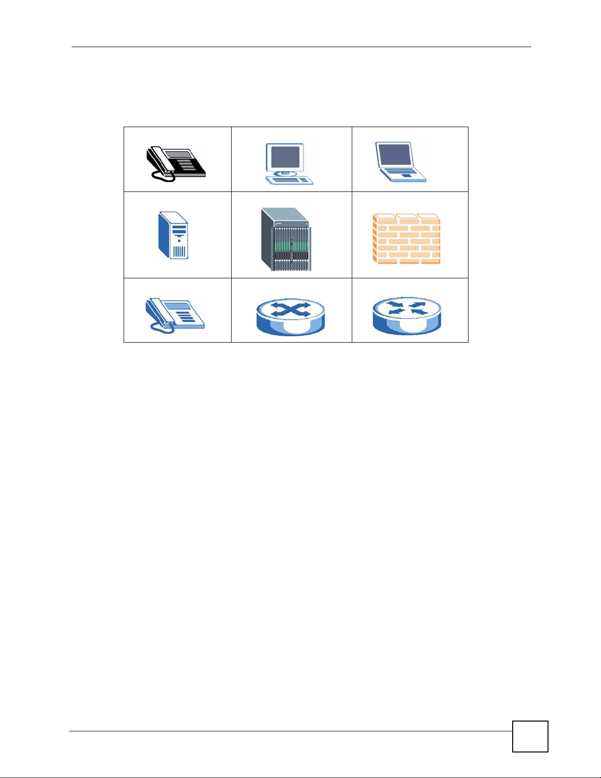
Icons Used in Figures
Figures in this User’s Guide may use the following generic icons. The V500 icon is not an
exact representation of your device.
V500 Computer Notebook computer
Server DSLAM Firewall
Telephone Switch Router
V500 Series User’s Guide
5
Page 6

Safety Warnings
Safety Warnings
1 For your safety, be sure to read and follow all warning notices and instructions.
• Do NOT use this product near water, for example, in a wet basement or near a swimming
pool.
• Do NOT expose your device to dampness, dust or corrosive liquids.
• Do NOT store things on the device.
• Do NOT install, use, or service this device during a thunderstorm. There is a remote risk
of electric shock from lightning.
• Connect ONLY suitable accessories to the device.
• Do NOT open the device or unit. Opening or removing covers can expose you to
dangerous high voltage points or other risks. ONLY qualified service personnel should
service or disassemble this device. Please contact your vendor for further information.
• Make sure to connect the cables to the correct ports.
• Place connecting cables carefully so that no one will step on them or stumble over them.
• Always disconnect all cables from this device before servicing or disassembling.
• Use ONLY an appropria t e power adaptor or cord for your device. Connect it to the right
supply voltage (for example, 110V AC in North America or 230V AC in Europe).
• Do NOT allow anything to rest on the power adaptor or cord and do NOT place the
product where anyone can walk on the power adaptor or cord.
• Do NOT use the device if the power adaptor or cord is damaged as it might cause
electrocution.
• If the power adaptor or cord is damaged, remove it from the device and the power source.
• Do NOT attempt to repair the power adaptor or cord. Contact your local vendor to order a
new one.
• Do not use the device outside, and make sure all the connections are indoors. There is a
remote risk of electric shock from lightning.
• Do NOT obstruct the device ventilation slots, as insufficient airflow may harm your
device.
• If you wall mount your device, make sure that no electrical lines, gas or water pipes will
be damaged.
• The PoE (Power over Ethernet) devices that supply or receive power and their connected
Ethernet cables must all be completely indoors.
6
This product is recyclable. Dispose of it properly.
V500 Series User’s Guide
Page 7

Safety Warnings
V500 Series User’s Guide
7
Page 8

Safety Warnings
8
V500 Series User’s Guide
Page 9

Contents Overview
Contents Overview
Introduction ............................................................................................................................29
Introduction .................................. .................................................... .......................................... 31
Hardware ................................................................................................................................... 35
Tutorials .....................................................................................................................................45
LCD Screen Menus ................................................................................................................59
Using the LCD Screen ...............................................................................................................61
The Phonebook ......................................................................................................................... 69
LCD Menus: Basic Settings .......................................................................................................77
LCD Menus: Advanced ............................................................................................................103
The Web Configurator .........................................................................................................159
Introducing the Web Configurator ............................................................................................ 161
Status Screens ........................................................................................................................ 167
Network Setup ......................................................................................................................... 173
SIP Account Setup ... ... ... .... ... ... ... .... ... ............................................................. ... .....................177
Phone Setup .................................................................................................... ... .... ... ... ........... 193
The Phone Book ......................................................................................................................201
Maintenance and Troubleshooting .....................................................................................211
System ................................... ...................... ....................... ....................... .............................. 213
Logs ....................................... .................................................... .............................................. 219
Tools ........................................................................................................................................221
Troubleshooting ..................................................... .................................................................. 227
Appendices and Index .........................................................................................................233
V500 Series User’s Guide
9
Page 10

Contents Overview
10
V500 Series User’s Guide
Page 11

Table of Contents
Table of Contents
About This User's Guide..........................................................................................................3
Document Conventions............................................................................................................4
Safety Warnings ........................................................................................................................6
Contents Overview ...................................................................................................................9
Table of Contents....................................................................................................................11
List of Figures.........................................................................................................................19
List of Tables...........................................................................................................................25
Part I: Introduction................................................................................. 29
Chapter 1
Introduction.............................................................................................................................31
1.1 Overview ............. .......................................................... ... .... ... ... .......................................... 31
1.2 Applications ........................... .... ... ... ... ... ........................................................... ... ... .............32
1.2.1 Make Calls via Internet Telephony Service Provider .................................................. 32
1.2.2 Make Calls via IP-PBX ............................................................................................... 33
1.2.3 Make Peer-to-peer Calls ........................................ .... ... ............................................. 33
1.3 Ways to Manage the V500 ........................... ... ... .... ... ... ... .... ................................................ 34
1.4 Good Habits for Managing the V500 ...................................................................................34
Chapter 2
Hardware..................................................................................................................................35
2.1 Overview ............. .......................................................... ... .... ... ... .......................................... 35
2.2 Physical Features ............................................................ .... ... ... ... ... .................................... 35
2.2.1 The LCD Screen ........................................................................................................40
2.2.2 Resetting the V500 .................... .......................................................... .... ... ... ... ... .......40
2.3 Phone Functions .............. .......................................................... ... ... .... ... ............................. 40
2.3.1 Making a Call ............ ... .... ... ... ... ... .... .......................................................... ... ... ... .... ... 40
2.3.2 Receiving a Call .........................................................................................................41
2.3.3 Ending a Call ................................................. ... .......................................................... 41
2.3.4 Changing the Volume .......................... ... ... .......................................................... .... ... 41
2.3.5 Muting a Call ............................................. .......................................................... ....... 42
2.3.6 Placing a Call on Hold ................................................................................................ 42
V500 Series User’s Guide
11
Page 12

Table of Contents
2.3.7 Using Voicemail ................................................... ... ....................................................42
2.3.8 Making Conference Calls ........................................................................................... 42
2.3.9 Transferring a Call ............... ... ... ... .... ... ... .......................................................... ... .... ...43
Chapter 3
Tutorials...................................................................................................................................45
3.1 Overview ............. .......................................................... ... .... ... ... .......................................... 45
3.2 Setting Up a Network Connection ....................................... ... ... ... ... .... ................................ 45
3.3 Configuring VoIP Options Automatically .................................................... .......................... 47
3.3.1 Configuring VoIP Options Manually ........................................................................... 48
3.4 Placing a Call ....................................................................................................................... 50
3.4.1 Receiving an Incoming Call on a 2nd Line .................................... ............................. 51
3.5 Making a Conference Call ...................................................................................................53
3.6 Retrieving Voice Mail .................................... ... ... .... ... ... ....................................................... 55
3.7 Setting the Time on Your V500 ........ ............................................................. .......................57
Part II: LCD Screen Menus.................................................................... 59
Chapter 4
Using the LCD Screen............................................................................................................61
4.1 Overview ............. .......................................................... ... .... ... ... .......................................... 61
4.2 The Navigation Pad ............................................................................................................. 61
4.3 The Keypad ..................................... ... .......................................................... .... ... ... ... .......... 62
4.4 Working with the LCD Menus .............................................................................................. 63
4.4.1 LCD Menu Syntax Conventions ................................................................................. 63
4.4.2 Entering Numbers, Letters and Symbols ................................................................... 64
4.5 Enabling and Disabling Features ......................................................................................... 64
4.6 LCD Menu Overview ...........................................................................................................65
4.7 The LCD Status Screen ....................................................................................................... 67
Chapter 5
The Phonebook.......................................................................................................................69
5.1 Overview ............. .......................................................... ... .... ... ... .......................................... 69
5.2 Add a Phonebook Entry ....................................................................................................... 69
5.3 Edit a Phonebook Entry .......................................................................................................72
5.4 Delete a Phonebook Entry ...................................................................................................73
5.5 Call a Phonebook Contact ......................................... ... ... .... ... ... ... ... .... ................................73
5.5.1 Search by Number ................................. ... .... ... ... ... .... ... ............................................. 74
5.5.2 Search by Name . ... ... ... .......................................................... .... ................................ 75
5.6 Calling a Number Not in the Phonebook .............................................................................75
12
V500 Series User’s Guide
Page 13

Table of Contents
Chapter 6
LCD Menus: Basic Settings...................................................................................................77
6.1 Overview ............. .......................................................... ... .... ... ... .......................................... 77
6.2 Entering the Menu System ..................................................................................................77
6.3 The System Info Menu ........................................... ... ... ... .... ... ... ... ... .... ... ... ..........................78
6.3.1 Firmware Version ................... ... ... .... ... .......................................................... ... ... .... ... 79
6.3.2 IP Address ........................... ... ... .......................................................... .... ... ... ... ..........79
6.3.3 VoIP Status .......................................... ... .......................................................... ... ....... 80
6.4 The Ring Setting Menu ........................................................................................................81
6.4.1 The Ring Type Menu ........................... ... ... .... ... ... ... .... ................................................ 82
6.5 The Volume Setting Menu ................................................................................................... 82
6.5.1 Volume Screen .................... ... ... ... .... ... .......................................................... ... ... .... ... 83
6.6 The Call Preference Menu ......................... ...................... ....................... ...................... .......84
6.6.1 Call Forward .................................................. ... ... ... .... ... ............................................. 85
6.7 The Phonebook Menu .........................................................................................................91
6.7.1 Contact List .................................. .... ... ... .......................................................... ... ....... 92
6.7.2 Caller Group ........................................................ ... .... ... ... ... ... .... ... ... ..........................92
6.7.3 Block List ................................................ ... .......................................................... ....... 94
6.7.4 DND White List ....................... .......................................................... ... .... ... ... ... ..........95
6.7.5 The Speed Dial Menu ................................................................................................. 96
6.8 The Advanced Setting Menu ...............................................................................................98
6.9 The System Restart Menu ................................................................................................... 99
6.10 The Logo Setting Menu ................................................................................................... 100
6.10.1 The Logo Setting - Edit Screen ..............................................................................101
Chapter 7
LCD Menus: Advanced .........................................................................................................103
7.1 Overview ............. .......................................................... ... .... ... ... ........................................ 103
7.1.1 What You Can Do in This Chapter ........................................................................... 103
7.2 The Advanced Setting Menu .............................................................................................103
7.3 The Network Setting Menu ................................................................................................ 104
7.3.1 The PPPoE Menu ....................................................................................................105
7.3.2 Static IP ............................................ ........................................................................109
7.3.3 DHCP .............. .... ... ... ... .... ... ... .......................................................... ... ......................115
7.4 The SIP Configuration Menus ............................................................................................116
7.4.1 Display Name ................................................ ... ... ... .... ...............................................117
7.4.2 SIP Number ......................... ... ... .......................................................... .... ... ... ... .........118
7.4.3 SIP Local Port ..........................................................................................................120
7.4.4 SIP Server Address .................................................................................................. 122
7.4.5 SIP Server Port ........................................................................................................123
7.4.6 SIP Register Server ................................................................................................. 125
7.4.7 SIP Register Port .....................................................................................................126
7.4.8 SIP Service Domain ................................................................................................. 128
V500 Series User’s Guide
13
Page 14

Table of Contents
7.4.9 SIP Authentication ID ............................................................................................... 129
7.4.10 Authentication Password ................ ............. ............. ............ ............. .......... ........... 131
7.4.11 Codec Priority ......................................................................................................... 132
7.4.12 Voicemail Number ..................................................................................................133
7.4.13 DNS SRV / DNS ..................................................................................................... 134
7.4.14 Call ID ....................................................................................................................135
7.4.15 NAT Setting ............................................................................................................135
7.4.16 Backup SIP Server (1 and 2) ................................................................................. 142
7.5 The Auto Provision Menus ................................................................................................144
7.5.1 Protocol ..................... ... .... ... .......................................................... ... ... .... ... ... ...........145
7.5.2 Auto-provisioning Server Address ............. .... ... ... ... .................................................. 1 46
7.5.3 Auto-provisioning Server Port ............................. ... .... ... ... ... ... .... ... ........................... 148
7.5.4 Expire Time .................. .... ... ... ... .......................................................... .... ... ... ... ........149
7.5.5 Retry Time ........................ ... .......................................................... ... ... .... ... ... ...........151
7.6 Programmable Key ....................................................................................................... ..... 152
7.7 Display Adjusting ...... ........................................................... ... ... ... ... .... .............................. 153
7.7.1 Contrast ........................ .... ... .......................................................... ... ... .... ... ..............154
7.7.2 Brightness ................................. ... .... ... .......................................................... ... ........154
7.8 Call Feature Mode ............................................................................................................. 155
7.8.1 PBX Mode ................................................................................................................ 156
7.9 Language Support .............. ... .... ... ... ... ... .... ............................................................. ... ... ..... 157
Part III: The Web Configurator............................................................ 159
Chapter 8
Introducing the Web Configurator ......................................................................................161
8.1 Overview ............. .......................................................... ... .... ... ... ........................................ 161
8.2 Accessing the Web Configurator ....................................................................................... 161
8.2.1 Title Bar ............................................ ... ... ... .... ... ... ... .................................................. 163
8.2.2 Navigation Panel ....................... ... .... ... ... ..................................................................164
8.2.3 Main Window .......................... ... .......................................................... .... ... ... ... ... .....165
8.2.4 Status Bar ............................................... ... ...............................................................165
Chapter 9
Status Screens......................................................................................................................167
9.1 Overview ............. .......................................................... ... .... ... ... ........................................ 167
9.2 Status Screen ..... ... ... .... ... ... ... .... ... .......................................................... ... ... .... ... ..............167
9.3 Packet Statistics .............................................................................. .... ... ... ... .... .................169
9.4 VoIP Statistics ..................................................... ............................................................... 170
Chapter 10
Network Setup.......................................................................................................................173
14
V500 Series User’s Guide
Page 15

Table of Contents
10.1 Overview .......................................................................................................................... 173
10.1.1 What You Can Do in This Chapter .........................................................................173
10.1.2 What You Need to Know ........................................................................................ 173
10.2 Internet Connection .........................................................................................................175
10.3 Management Port ............................................................................................................ 176
Chapter 11
SIP Account Setup................................................................................................................177
11.1 Overview .......................................................................................................................... 177
11.1.1 What You Can Do in This Chapter .........................................................................177
11.1.2 What You Need to Know ........................................................................................ 177
11.2 SIP Settings Screen ......................................................................................................... 178
11.2.1 Advanced SIP Setup Screen ................................ .................................................. 181
11.3 SIP QoS Screen ............................................................................................................... 185
11.4 Technical Reference ........................................................................................................185
Chapter 12
Phone Setup..........................................................................................................................193
12.1 Overview .......................................................................................................................... 193
12.1.1 What You Can Do in This Chapter .........................................................................193
12.2 Phone Settings Screen ....................................................................................................194
12.2.1 Voice Activity Detection/Silence Suppression ........................................................ 195
12.2.2 Comfort Noise Generation ..................................................................................... 196
12.2.3 Echo Cancellation .................................................................................................. 196
12.3 Phone Region Screen ....................................................................................................196
12.4 Speed Dial Settings Screen ............................................................................................ 196
12.5 Programmable Feature Key Settings Screen ............. ... .... ... ... ........................................ 198
Chapter 13
The Phone Book....................................................................................................................201
13.1 Overview .......................................................................................................................... 201
13.1.1 What You Can Do in This Chapter .........................................................................201
13.2 Call Forward Screen ........................................................................................................202
13.3 Contact List Screen .........................................................................................................204
13.4 Group List Screen ............................................................................................................ 206
13.5 Block List Screen .............................................................................................................207
13.6 DND White List Screen .................................................................................................... 208
Part IV: Maintenance and Troubleshooting ........................................211
Chapter 14
System...................................................................................................................................213
V500 Series User’s Guide
15
Page 16

Table of Contents
14.1 Overview .......................................................................................................................... 213
14.1.1 What You Can Do in This Chapter .........................................................................213
14.2 The General Screen .......................................................................................................213
14.3 Time Setting Screen ........................................................................................................ 216
Chapter 15
Logs .......................................................................................................................................219
15.1 Overview .......................................................................................................................... 219
15.2 Logs Screen ....... ... .... ... ... ... .... .......................................................... ... ... ... .... ... ... ... ........219
Chapter 16
Tools.......................................................................................................................................221
16.1 Overview .......................................................................................................................... 221
16.1.1 What You Can Do in This Chapter .........................................................................221
16.2 Firmware Upload Screen ............................................ ... .... ... ... ... ..................................... 221
16.3 Configuration Screen .......................................................................................................223
16.3.1 Backup Configuration ........................ ....................................... .............................. 2 23
16.3.2 Restore Configuration ............................................................................................ 224
16.3.3 Back to Factory Defaults ................... ... ... .......................................................... .... . 225
16.4 Restart Screen ................................................................................................................. 225
16.5 Ring Maintenance Screen ...............................................................................................225
Chapter 17
Troubleshooting....................................................................................................................227
17.1 Overview .......................................................................................................................... 227
17.2 Power, Hardware Connections, and LEDs .... ... .... ... ... ... .... ... ........................................... 227
17.3 V500 Access and Login ..................................................................................................228
17.4 Internet Access ................................................................................................................230
17.5 Phone Calls and VoIP ......................................................................................................231
Part V: Appendices and Index ............................................................ 233
Appendix A Product Specifications.......................................................................................235
Appendix B Setting Up Your Computer’s IP Address...........................................................241
Appendix C Pop-up Windows, JavaScripts and Java Permissions......................................265
Appendix D IP Addresses and Subnetting ...........................................................................271
Appendix E Legal Information ..............................................................................................279
Appendix F Customer Support.............................................................................................283
16
V500 Series User’s Guide
Page 17

Table of Contents
Index.......................................................................................................................................289
V500 Series User’s Guide
17
Page 18

Table of Contents
18
V500 Series User’s Guide
Page 19

List of Figures
List of Figures
Figure 1 Internet Telephony Service Provider Application .. ... .... ... ... ... .... ... ... ... ... .... ... ... .......................... 32
Figure 2 IP-PBX Application .................................................................................................................. 33
Figure 3 Peer-to-peer Calling .................................................................................................................33
Figure 4 Front Panel Hardware .............................................................................................................35
Figure 5 Side Panel ................................................................................................................................ 38
Figure 6 Rear Panel Hardware ............................. ................................................. ................................ 39
Figure 7 The V500 LCD Screen and Navigation Pad ............................................................................. 61
Figure 8 The V500 Keypad ..................................................................................................................... 62
Figure 9 Drilling Down ............................................................................................................................ 63
Figure 10 LCD Status Screen ................................................................................................................. 67
Figure 11 LCD Public / Private Phonebooks ..........................................................................................69
Figure 12 LCD Contact List .................................................................................................................... 70
Figure 13 LCD Contact List - Add.. ......................................................................................................... 70
Figure 14 LCD Caller Group ................................................................................................................... 71
Figure 15 LCD Assign Account .............................................................................................................71
Figure 16 LCD Assign Account .............................................................................................................72
Figure 17 LCD Contact List - Edit ..........................................................................................................72
Figure 18 LCD Contact List - Delete ....................................................................................................... 73
Figure 19 LCD Dial Screen .................................................................................................................... 73
Figure 20 LCD Search by Number Example 1 ......................................................................................74
Figure 21 LCD Search by Number Example 2 ......................................................................................75
Figure 22 LCD Menu Setting .................................................................................................................. 77
Figure 23 LCD Menu: System Info ........................................................................................................ 78
Figure 24 LCD Menu: Firmware Version ................................................................................................ 79
Figure 25 LCD Menu: IP Address........................................................................................................... 79
Figure 26 LCD Menu: VoIP Status ......................................................................................................... 80
Figure 27 LCD Menu: Ring Setting ........................................................................................................ 81
Figure 28 LCD Menu: Ring Type ............................................................................................................82
Figure 29 LCD Menu: Volume Setting ...................................................................................................82
Figure 30 LCD Menu: Volume Screen ................................................................................................... 83
Figure 31 LCD Menu: Call Preference ...................................................................................................84
Figure 32 LCD Menu: Call Forward........................................................................................................ 85
Figure 33 LCD Menu: Conditional Forward............................................................................................ 86
Figure 34 LCD Menu: Forward Number .................... .... ... ... ... .... ............................................................ 87
Figure 35 LCD Menu: Forward Number - Edit ........................................................................................ 87
Figure 36 LCD Menu: Specific Forward Entry Table ...............................................................................88
Figure 37 LCD Menu: Specific Forward Entry ....................................................................................... 89
Figure 38 LCD Menu: Incoming Call Number........................................................................................ 90
V500 Series User’s Guide
19
Page 20

List of Figures
Figure 39 LCD Menu: Forward to Number ........................... .......................................................... ....... 90
Figure 40 LCD Menu: Condition ............................................................................................................ 91
Figure 41 LCD Menu: Phonebook.......................................................................................................... 91
Figure 42 LCD Menu: Caller Group......................................................................................... ... ............ 93
Figure 43 LCD Menu: Caller Group List ................................................................................................. 93
Figure 44 LCD Menu: Block List............................................................................................................. 94
Figure 45 LCD Menu: DND White List.................................................................................................... 95
Figure 46 LCD Menu: Speed Dial........................................................................................................... 96
Figure 47 LCD Menu: Speed Dial - Edit ................................................................................................. 97
Figure 48 LCD Menu: Speed Dial - Edit Phonebook.............................................................................. 98
Figure 49 LCD Menu: System Restart ................................................................................................... 99
Figure 50 LCD Menu: Logo Setting Menu ........................................................................................... 100
Figure 51 LCD Menu: Logo Setting - Edit ............................................................................................101
Figure 52 LCD Menu: Advanced Setting.............................................................................................. 103
Figure 53 LCD Menu: Network Setting ................................................................................................104
Figure 54 LCD Menu: PPPoE .............................................................................................................. 105
Figure 55 LCD Menu: PPPoE Username............................................................................................. 106
Figure 56 LCD Menu: PPPoE Username - Edit ................................................................................... 106
Figure 57 LCD Menu: PPPoE Password.............................................................................................. 107
Figure 58 LCD Menu: PPPoE Password - Edit .................................................................................... 108
Figure 59 LCD Menu: Static IP............................................................................................................. 109
Figure 60 LCD Menu: IP Address.......................................................................................................... 110
Figure 61 LCD Menu: IP Address - Edit ................................................................................................ 110
Figure 62 LCD Menu: Default Gateway................................................................................................. 111
Figure 63 LCD Menu: Default Gateway - Edit ....................................................................................... 112
Figure 64 LCD Menu: Subnet Mask ...................................................................................................... 113
Figure 65 LCD Menu: Subnet Mask - Edit ............................................................................................113
Figure 66 LCD Menu: First / Second DNS ............................................................................................ 114
Figure 67 LCD Menu: First / Second DNS - Edit................................................................................... 115
Figure 68 LCD Menu: SIP Configuration............................................................................................... 116
Figure 69 LCD Menu: Display Name..................................................................................................... 117
Figure 70 LCD Menu: Display Name - Edit ........................................................................................... 118
Figure 71 LCD Menu: SIP Number........................................................................................................ 119
Figure 72 LCD Menu: SIP Number - Edit ............... ... .... ... ... ... .... ... ........................................................ 119
Figure 73 LCD Menu: SIP Local Port ................................................................................................... 120
Figure 74 LCD Menu: SIP Local Port - Edit.......................................................................................... 121
Figure 75 LCD Menu: SIP Server Address........................................................................................... 122
Figure 76 LCD Menu: SIP Server Address - Edit ....................... ... ... ... .... ... ... ... ... .... ... ... ... .................... 122
Figure 77 LCD Menu: SIP Server Port ................................................................................................. 123
Figure 78 LCD Menu: SIP Server Port - Edit........................................................................................ 124
Figure 79 LCD Menu: SIP Register Server .......................................................................................... 125
Figure 80 LCD Menu: SIP Register Server Address - Edit................................................................... 125
Figure 81 LCD Menu: SIP Register Port .............................................................................................. 126
20
V500 Series User’s Guide
Page 21

List of Figures
Figure 82 LCD Menu: SIP Register Port - Edit..................................................................................... 127
Figure 83 LCD Menu: SIP Service Domain.......................................................................................... 128
Figure 84 LCD Menu: SIP Service Domain - Edit................................................................................. 128
Figure 85 LCD Menu: SIP Authentication ID........................................................................................ 129
Figure 86 LCD Menu: SIP Authentication ID - Edit............................................................................... 130
Figure 87 LCD Menu: Authentication Password................................................................................... 131
Figure 88 LCD Menu: Authentication Password - Edit ......................................................................... 131
Figure 89 LCD Menu: Codec Selection................................................................................................ 132
Figure 90 LCD Menu: Voicemail Number............................................................................................. 133
Figure 91 LCD Menu: Voicemail Number - Edit.................................................................................... 134
Figure 92 LCD Menu: NAT Setting....................................................................................................... 135
Figure 93 LCD Menu: STUN ...............................................................................................................136
Figure 94 LCD Menu: STUN Server Address....................................................................................... 136
Figure 95 LCD Menu: STUN Server Address - Edit ............................................................................137
Figure 96 LCD Menu: STUN Server Port ............................................................................................138
Figure 97 LCD Menu: STUN Server Port - Edit ...................................................................................138
Figure 98 LCD Menu: Outbound Proxy ................................................................................................ 139
Figure 99 LCD Menu: Outbound Proxy Server Address ..................................................................... 140
Figure 100 LCD Menu: Outbound Proxy Server Address - Edit ..........................................................140
Figure 101 LCD Menu: Outbound Proxy Server Port........................................................................... 141
Figure 102 LCD Menu: Outbound Proxy Server Port - Edit.................................................................. 142
Figure 103 LCD Menu: Backup SIP Server ......................................................................................... 143
Figure 104 LCD Menu: First / Second Backup SIP Server ..................................................................143
Figure 105 LCD Menu: Auto Provision ................................................................................................ 144
Figure 106 LCD Menu: Auto Provision Protocol ..................................................................................145
Figure 107 LCD Menu: Auto Provision Protocol - Edit ................................ ........................................ 146
Figure 108 LCD Menu: Auto Provision Server Address ...................................................................... 146
Figure 109 LCD Menu: Auto Provision Server Address - Edit ............................................................. 147
Figure 110 LCD Menu: Auto Provision Server Port ............................................................................. 148
Figure 111 LCD Menu: Auto Provision Server Port - Edit ..... .......................................................... .... . 148
Figure 112 LCD Menu: Auto Provision Expire Time ............................................................................ 149
Figure 113 LCD Menu: Auto Provision Expire Time - Edit ...................................................................150
Figure 114 LCD Menu: Auto Provision Retry Time ..............................................................................151
Figure 115 LCD Menu: Auto Provision Retry Time - Edit ......... ... ... ..................................................... 151
Figure 116 LCD Menu: Programmable Feature Key ...........................................................................152
Figure 117 LCD Menu: Display Adjusting ............................................................................................153
Figure 118 LCD Menu: Contrast .......................................................................................................... 154
Figure 119 LCD Menu: Brightness ......................................................................................................154
Figure 120 LCD Menu: Call Feature Mode .......................................................................................... 155
Figure 121 LCD Menu: Call Feature Mode .......................................................................................... 156
Figure 122 LCD Menu: Language Support ..........................................................................................157
Figure 123 Password Screen ..............................................................................................................161
Figure 124 Change Password Screen .................................................................................................. 162
V500 Series User’s Guide
21
Page 22

List of Figures
Figure 125 The Status Screen ............................................................................................................. 163
Figure 126 Status Screen .....................................................................................................................167
Figure 127 Packet Statistics ................................................................................................................. 169
Figure 128 VoIP Statistics ..................................................................................................................... 170
Figure 129 Network > Internet Connection ........................................................................................... 175
Figure 130 Network > Mgnt Port ...........................................................................................................176
Figure 131 VoIP > SIP > SIP Settings .................................................................................................. 178
Figure 132 VoIP > SIP > SIP Settings > Advanced .............................................................................. 181
Figure 133 VoIP > SIP > QoS ...............................................................................................................185
Figure 134 SIP User Agent ................................................................................................................... 187
Figure 135 SIP Proxy Server ................................................................................................................187
Figure 136 SIP Redirect Server ............................................................................................................ 188
Figure 137 STUN .................................................................................................................................. 189
Figure 138 DiffServ: Differentiated Service Field .................................................................................. 191
Figure 139 VoIP > Phone > Phone Settings .........................................................................................194
Figure 140 VoIP > Phone > Region ...................................................................................................... 196
Figure 141 Phone Book > Speed Dial .................................................................................................. 197
Figure 142 VoIP > Phone > Programmable Feature Key Settings ....................................................... 198
Figure 143 VoIP > Phone Book > Call Forward ....................................................................................202
Figure 144 VoIP > Phone Book > Contact List ..................................................................................... 204
Figure 145 VoIP > Phone Book > Group List ....................................................................................... 206
Figure 146 VoIP > Phone Book > Block List ........................................................................................ 207
Figure 147 VoIP > Phone Book > DND White List ............................................................................... 208
Figure 148 Maintenance > System > General ......................................................................................214
Figure 149 Maintenance > Time Setting ...............................................................................................216
Figure 150 Maintenance > Logs ...........................................................................................................219
Figure 151 Maintenance > Tools > Firmware Upload ...........................................................................221
Figure 152 Upload Warning .................................................................................................................. 222
Figure 153 Network Temporarily Disconnected ....................................................................................222
Figure 154 Upload Error Message ....................................................................................................... 223
Figure 155 Maintenance > Tools > Configuration .................................................................................223
Figure 156 Configuration Upload Successful .......................................................................................224
Figure 157 Temporarily Disconnected .................................................................................................. 224
Figure 158 Configuration Restore Error ............................................................................................... 225
Figure 159 Maintenance > Tools > Restart ........................................................................................... 225
Figure 160 Maintenance > Tools > Ring Maintenance ......................................................................... 226
Figure 161 Wall-mounting Example ...................................................................................................... 239
Figure 162 Masonry Plug and M4 Tap Screw .......................................................................................240
Figure 163 Windows XP: Start Menu .................................................................................................... 242
Figure 164 Windows XP: Control Panel ...............................................................................................242
Figure 165 Windows XP: Control Panel > Network Connections > Properties ......................... ... ... .... . 243
Figure 166 Windows XP: Local Area Connection Properties ............................................................... 243
Figure 167 Windows XP: Internet Protocol (TCP/IP) Properties .................. ... ... .... ... ... ... .... ... ... ... ........244
22
V500 Series User’s Guide
Page 23

List of Figures
Figure 168 Windows Vista: Start Menu ................................................................................................. 245
Figure 169 Windows Vista: Control Panel ............................................................................................ 245
Figure 170 Windows Vista: Network And Internet ................................................................................ 245
Figure 171 Windows Vista: Network and Sharing Center ..................................................................... 246
Figure 172 Windows Vista: Network and Sharing Center ..................................................................... 246
Figure 173 Windows Vista: Local Area Connection Properties ............................................................ 247
Figure 174 Windows Vista: Internet Protocol Version 4 (TCP/IPv4) Properties ...................................248
Figure 175 Mac OS X 10.4: Apple Menu .............................................................................................. 249
Figure 176 Mac OS X 10.4: System Preferences ................................................................................. 249
Figure 177 Mac OS X 10.4: Network Preferences ............................................................................... 250
Figure 178 Mac OS X 10.4: Network Preferences > TCP/IP Tab. ........................................................250
Figure 179 Mac OS X 10.4: Network Preferences > Ethernet ................ ................................... ........... 251
Figure 180 Mac OS X 10.4: Network Utility .......................................................................................... 251
Figure 181 Mac OS X 10.5: Apple Menu .............................................................................................. 252
Figure 182 Mac OS X 10.5: Systems Preferences ............................................................................... 252
Figure 183 Mac OS X 10.5: Network Preferences > Ethernet ................ ................................... ........... 253
Figure 184 Mac OS X 10.5: Network Preferences > Ethernet ................ ................................... ........... 254
Figure 185 Mac OS X 10.5: Network Utility .......................................................................................... 254
Figure 186 Ubuntu 8: System > Administration Menu ..........................................................................255
Figure 187 Ubuntu 8: Network Settings > Connections ...................... .... .............................................. 2 55
Figure 188 Ubuntu 8: Administrator Account Authentication ................................................................ 256
Figure 189 Ubuntu 8: Network Settings > Connections ...................... .... .............................................. 2 56
Figure 190 Ubuntu 8: Network Settings > Properties ........................................................................... 257
Figure 191 Ubuntu 8: Network Settings > DNS ...................................................................................257
Figure 192 Ubuntu 8: Network Tools .................................................................................................... 258
Figure 193 openSUSE 10.3: K Menu > Computer Menu .....................................................................259
Figure 194 openSUSE 10.3: K Menu > Computer Menu .....................................................................259
Figure 195 openSUSE 10.3: YaST Control Center ..............................................................................260
Figure 196 openSUSE 10.3: Network Settings ....................................................................................260
Figure 197 openSUSE 10.3: Network Card Setup ...............................................................................261
Figure 198 openSUSE 10.3: Network Settings ....................................................................................262
Figure 199 openSUSE 10.3: KNetwork Manager ................................................................................. 263
Figure 200 openSUSE: Connection Status - KNetwork Manager ........................................................263
Figure 201 Pop-up Blocker ...................................................................................................................265
Figure 202 Internet Options: Privacy .................................................................................................... 266
Figure 203 Internet Options: Privacy .................................................................................................... 267
Figure 204 Pop-up Blocker Settings .....................................................................................................267
Figure 205 Internet Options: Security ................................................................................................... 268
Figure 206 Security Settings - Java Scripting ....................................................................................... 269
Figure 207 Security Settings - Java ...................................................................................................... 269
Figure 208 Java (Sun) .......................................................................................................................... 270
Figure 209 Network Number and Host ID ............................................................................................ 272
Figure 210 Subnetting Example: Before Subnetting ....................................... ... .... ... ... ... .....................274
V500 Series User’s Guide
23
Page 24

List of Figures
Figure 211 Subnetting Example: After Subnetting ................................................................................275
24
V500 Series User’s Guide
Page 25

List of Tables
List of Tables
Table 1 Models Covered ........................................................................................................................ 32
Table 2 Front Panel Hardware ............................................................................................................... 36
Table 3 Side Panel Hardware ................................................................................................................ 38
Table 4 Rear Panel Hardware ............................................................................................................... 39
Table 5 Keypad Characters ...................................................................................................................64
Table 6 LCD Menu Overview ................................................................................................................. 65
Table 7 LCD Status Screen ................................................................................................................... 67
Table 8 LCD Menu: System Info ............................................................................................................ 78
Table 9 LCD Menu: IP Address ............................................................................................................. 79
Table 10 LCD Menu: VoIP Status ................ ... ............................................................. ... .......................80
Table 11 LCD Menu: Ring Setting ......................................................................................................... 81
Table 12 LCD Menu: Ring Type ............................................................................................................. 82
Table 13 LCD Menu: Volume Setting .....................................................................................................83
Table 14 LCD Menu: Volume Setting .....................................................................................................83
Table 15 LCD Menu: System Info .......................................................................................................... 84
Table 16 LCD Menu: Call Forward .................... ... ... .... ... ... ... .... ... ... ... .... ... ............................................. 85
Table 17 LCD Menu: Conditional Forward ............................................................................................. 86
Table 18 LCD Menu: Forward Number .................................................................................................. 87
Table 19 LCD Menu: Forward Number - Edit ........................................................................................ 88
Table 20 LCD Menu: S pecific Forward Entry Table ...............................................................................88
Table 21 LCD Menu: S pecific Forward Entry ......................................................................................... 89
Table 22 LCD Menu: Phonebook .................................................... ... .... ... ... ... ... .... ... ............................. 92
Table 23 LCD Menu: Caller Group .................... ... ... .... ... ... ... .... ... ... ... .... ... ............................................. 93
Table 24 LCD Menu: Block List ............................................................................................................. 94
Table 25 LCD Menu: Block List ............................................................................................................. 95
Table 26 LCD Menu: Sp eed Dial ...........................................................................................................96
Table 27 LCD Menu: Speed Dial - Edit .................................................................................................. 97
Table 28 LCD Menu: System Restart .................................................................................................... 99
Table 29 LCD Menu: Logo Setting Menu .............................................................................................100
Table 30 LCD Menu: Logo Setting - Edit ............................................................................................. 101
Table 31 LCD Menu: Network Setting ............................ ... ... ............................................................... 104
Table 32 LCD Menu: PPPoE ............................................................................................................... 105
Table 33 LCD Menu: PPPoE Username .............................................................................................. 106
Table 34 LCD Menu: PPPoE Username - Edit ....................................................................................107
Table 35 LCD Menu: PPPoE Password ..............................................................................................107
Table 36 LCD Menu: PPPoE Username - Edit ....................................................................................108
Table 37 LCD Menu: Static IP .............................................................................................................. 109
Table 38 LCD Menu: IP Address ..........................................................................................................110
V500 Series User’s Guide
25
Page 26

List of Tables
Table 39 LCD Menu: IP Address - Edit .................................................................................................111
Table 40 LCD Menu: Default Gateway ........... ......................................................................................111
Table 41 LCD Menu: Default Gateway - Edit ........................................................................................112
Table 42 LCD Menu: Subnet Mask .............. ... ... ... ... .... ... ... ...................................................................113
Table 43 LCD Menu: Subnet Mask - Edit .................... ... ... ... .... ... ... ... .... ... ... ... ......................................114
Table 44 LCD Menu: First / Second DNS .............................................................................................114
Table 45 LCD Menu: First / Second DNS - Edit ....................................................................................115
Table 46 LCD Menu: SIP Account Configuration ..................................................................................116
Table 47 LCD Menu: Display Name .....................................................................................................117
Table 48 LCD Menu: Display Name - Edit ............................................................................................118
Table 49 LCD Menu: SIP Number ........................................................................................................119
Table 50 LCD Menu: SIP Number - Edit .............................................................................................. 120
Table 51 LCD Menu: SIP Local Port ..................... ... .... ... ... ... .... ... ... ... .... ... ... ... ... .... ... ........................... 120
Table 52 LCD Menu: SIP Local Port - Edit ............................... ........................................................... 121
Table 53 LCD Menu: SIP Server Address ........................................................................................... 122
Table 54 LCD Menu: SIP Server Address - Edit ..................................................................................123
Table 55 LCD Menu: SIP Server Port .................................................................................................. 123
Table 56 LCD Menu: SIP Server Port - Edit ........................................................................................124
Table 57 LCD Menu: SIP Register Server Address ............................................................................. 125
Table 58 LCD Menu: SIP Register Server Address - Edit ...................................................................126
Table 59 LCD Menu: SIP Register Port ...............................................................................................126
Table 60 LCD Menu: SIP Register Port - Edit ......................................................................................127
Table 61 LCD Menu: SIP Service Domain ...........................................................................................128
Table 62 LCD Menu: SIP Service Domain - Edit ................................................................................. 129
Table 63 LCD Menu: SIP Authentication ID .........................................................................................129
Table 64 LCD Menu: SIP Authentication ID - Edit ...............................................................................130
Table 65 LCD Menu: Authentication Password ................................................................................... 131
Table 66 LCD Menu: Authentication Password - Edit ........................................ .................................. 132
Table 67 LCD Menu: Voicemail Number ...................... ... ... ... .... ... ... ... .... ... ... ... ... .... ... ... ... .... ... ... ... ... ..... 133
Table 68 LCD Menu: Voicemail Number - Edit ....................................................................................134
Table 69 LCD Menu: STUN ................................................................................................................. 136
Table 70 LCD Menu: STUN Server Address ....................................................................................... 137
Table 71 LCD Menu: STUN Server Address - Edit .............................................................................. 137
Table 72 LCD Menu: STUN Server Port .............................................................................................. 138
Table 73 LCD Menu: STUN Server Port - Edit ....................................................................................139
Table 74 LCD Menu: Outbound Proxy ................................................................................................. 139
Table 75 LCD Menu: Outbound Proxy Server Address ....................................................................... 140
Table 76 LCD Menu: Outbound Proxy Server Address - Edit ................... ... ........................................ 141
Table 77 LCD Menu: Outbound Proxy Server Port ..............................................................................141
Table 78 LCD Menu: Outbound Proxy Server Port - Edit .................................................................... 142
Table 79 LCD Menu: First / Second Backup SIP Server ..................................................................... 144
Table 80 LCD Menu: Auto Provision ....................................................................................................144
Table 81 LCD Menu: Auto Provision Protocol .....................................................................................145
26
V500 Series User’s Guide
Page 27

List of Tables
Table 82 LCD Menu: Auto Provision Protocol - Edit ............................................................................ 146
Table 83 LCD Menu: Auto Provision Server Address .................. ... ..................................................... 1 47
Table 84 LCD Menu: Auto Provision Server Address - Edit ..................... ........................................... 147
Table 85 LCD Menu: Auto Provision Server Address .................. ... ..................................................... 1 48
Table 86 LCD Menu: Auto Provision Server Port - Edit ....................................................................... 149
Table 87 LCD Menu: Auto Provision Expire Time ................................................................................ 149
Table 88 LCD Menu: Auto Provision Expire Time - Edit ...................................................................... 150
Table 89 LCD Menu: Auto Provision Retry Time .................................................................................151
Table 90 LCD Menu: Auto Provision Expire Time - Edit ...................................................................... 152
Table 91 LCD Menu: Programmable Key ............................................................................................153
Table 92 LCD Menu: Display Adjusting ............................................................................................... 153
Table 93 LCD Menu: Contrast .............................................................................................................154
Table 94 LCD Menu: Brightness .............. .... ... ... ... ... .... ... ... ..................................................................155
Table 95 LCD Menu: Contrast .............................................................................................................155
Table 96 LCD Menu: Contrast .............................................................................................................156
Table 97 LCD Menu: Contrast .............................................................................................................157
Table 98 Web Configurator Icons in the Title Bar ................................................................................163
Table 99 Navigation Panel Summary ..................................................................................................164
Table 100 Status Screen ...................................................................................................................... 168
Table 101 Packet Statistics ..................................................................................................................169
Table 102 VoIP Statistics .....................................................................................................................170
Table 103 Private IP Address Ranges ................................................................................................. 173
Table 104 Network > Internet Connection ...........................................................................................175
Table 105 Network > Mgnt Port ........................................................................................................... 176
Table 106 VoIP > SIP > SIP Settings ................................................................................................... 179
Table 107 VoIP > SIP > SIP Settings > Advanced Setup .................................................................... 182
Table 108 VoIP > SIP > QoS ...............................................................................................................185
Table 109 SIP Call Progression ........................................................................................................... 186
Table 110 VoIP > Phone > Phone Settings .......................................................................................... 194
Table 111 VoIP > Phone > Region ....................................................................................................... 196
Table 112 Phone Book > Speed Dial ...................................................................................................197
Table 113 Phone Book > Programmable Feature Key Settings ..........................................................198
Table 114 VoIP > Phone Book > Call Forward ....................................................................................202
Table 115 VoIP > Phone Book > Contact List ......................................................................................204
Table 116 VoIP > Phone Book > Group List ........................................................................................ 206
Table 117 VoIP > Phone Book > Block List .........................................................................................207
Table 118 VoIP > Phone Book > DND White List ................................................................................ 209
Table 119 Maintenance > System > General .......................................................................................214
Table 120 Maintenance > Time Setting ...............................................................................................216
Table 121 Maintenance > Logs ........................................................................................................... 219
Table 122 Maintenance > Tools > Firmware Upload ........................................................................... 222
Table 123 Maintenance > Tools > Configuration > Restore ................................... ... ... ... .....................224
Table 124 Maintenance > Tools > Ring Maintenance .......................................................................... 226
V500 Series User’s Guide
27
Page 28

List of Tables
Table 125 Hardware Specifications ..................................................................................................... 235
Table 126 Firmware Specifications ......................................................................................................236
Table 127 Standards Supported ..........................................................................................................237
Table 128 Power over Ethernet Injector Specifications ....... .......................................................... .... . 238
Table 129 Power over Ethernet Injector RJ-45 Port Pin Assignments ................................................ 238
Table 130 IP Address Network Number and Host ID Example ...........................................................272
Table 131 Subnet Masks .....................................................................................................................273
Table 132 Maximum Host Numbers ....................................................................................................273
Table 133 Alternative Subnet Mask Notation .......................................................................................273
Table 134 Subnet 1 .............................................................................................................................. 275
Table 135 Subnet 2 .............................................................................................................................. 276
Table 136 Subnet 3 .............................................................................................................................. 276
Table 137 Subnet 4 .............................................................................................................................. 276
Table 138 Eight Subnets ......................................................................................................................276
Table 139 24-bit Network Number Subnet Planning ............................................................................ 277
Table 140 16-bit Network Number Subnet Planning ............................................................................ 277
28
V500 Series User’s Guide
Page 29

Introduction
Introduction (31)
Hardware (35)
Tutorials (45)
PART I
29
Page 30

30
Page 31

CHAPTER 1
Introduction
1.1 Overview
This chapter introduces the main applications and features of the V500 Series. It also
introduces the ways you can manage your device.
" The V500 Series includes the V500-T1 and the V501-T1. Illustrations used
throughout this book are based on the V500-T1.
The V500 is an IP phone that allows you to make phone calls over the Internet. Sending voice
signals over the Internet is called Voice over IP (VoIP). VoIP allows you to call other IP
phones, mobile phones or landlines all over the world.
The V500 is packed with features - including multiple phone lines, multiple SIP accounts,
phonebook, conference calls, call transfer, call hold, and many more.
You can configure and manage the V500 directly, using its multi-function keypad and LCD
screen. Alternatively, access the internal web configurator using a computer connected to the
network for remote administrative configuration.
The V500’s Ethernet ports allow you to connect it to your Local Area Network (LAN) and
your computer. Your computer can access the LAN through the V500, as shown in the
following figure. A is your computer, B is your V500 and C is your modem or router.
V500 Series User’s Guide
31
Page 32

Chapter 1 Introduction
At the time of writing, this User’s Guide covers the following models.
Table 1 Models Covered
V500 IP phone.
V501 IP phone with Power over Ethernet (PoE) capability.
1.2 Applications
Here are some examples of how you can use your V500.
1.2.1 Make Calls via Internet Telephony Service Provider
In a home or small office environment, you can use the V500 to make and receive VoIP
telephone calls through an Internet Telephony Service Provider (ITSP).
The following figure shows a basic example of how you make a VoIP call through an ITSP. In
this example, you make a call from your V500 (A in the figure), which sends the call through
your modem or router (B) to the Internet and the ITSP’s SIP server (C). The VoIP call server
forwards calls to PSTN (Public Switched Telephone Network) phones through a trunking
gateway (D) to phones on the PSTN network (E). The VoIP call server also forwards calls to
IP phones (F) through the Internet.
Figure 1 Internet Telephony Service Provider Application
32
V500 Series User’s Guide
Page 33

1.2.2 Make Calls via IP-PBX
If your company has an IP-PBX (Internet Protocol Private Branch Exchange), you can use the
V500 to make and receive VoIP telephone calls through it.
In this example, you make a call from your V500 (A in the figure), which sends it to the IPPBX. The IP-PBX forwards calls to PSTN phones (B) on the PSTN network. The IP-PBX also
forwards calls to IP phones (C) through an IP network (this could include the Internet).
Figure 2 IP-PBX Application
Chapter 1 Introduction
1.2.3 Make Peer-to-peer Calls
Use the V500 to make a call to the recipient’s IP address wi thou t usi ng a SIP server. Peer-topeer calls are also called “Point to Point” or “IP-to-IP” calls. You must know the peer’s IP
address in order to do this.
The following figure shows a basic example of how you would make a peer-to-peer VoIP call.
You make a call on your V500 (A), which sends your call through your modem or router (B)
and the Internet to the peer VoIP device (C).
Figure 3 Peer-to-peer Calling
V500 Series User’s Guide
33
Page 34

Chapter 1 Introduction
1.3 Ways to Manage the V500
Use any of the following methods to manage the V500.
• Hardware keys. Use the control keys and LCD menus on the V500 for basic configuration.
• Web Configurator. This is recommended for everyday management of the V500 using a
(supported) web browser.
• FTP. Use File Transfer Protocol for firmware upgrades and configuration backup/restore.
• SPTGEN. SPTGEN is a text configuration file that you can edit and upload to the device.
This is especially convenient if you need to configure many devices of the same type.
1.4 Good Habits for Managing the V500
Do the following things regularly to make the V500 more secure and to manage the V500
more effectively.
• Change the web configurator password. Use a password that’s not easy to guess and that
consists of different types of characters, such as numbers and letters.
• Write down the password and put it in a safe place.
• Keep the V500 in a safe place. The LCD menus are not password-protected, so anyone
using the phone can access your phonebook, SIP account information, etc.
• Back up the configuration (and make sure you know how to restore it). Restoring an
earlier working configuration may be useful if the device becomes unstable or even
crashes. If you forget your password, you will have to reset the V500 to its factory default
settings to access the web configurator. If you backed up an earlier configuration file, you
would not have to totally re-configure the V500. You could simply restore your last
configuration.
34
V500 Series User’s Guide
Page 35

CHAPTER 2
Hardware
2.1 Overview
This chapter describes the V500’s physical features, and how to use its phone functions.
2.2 Physical Features
This section discusses the V500’s front, side and rear panel hardware features. See your Quick
Start Guide for descriptions of how to set up the V500’s hardware and network connections.
Figure 4 Front Panel Hardware
V500 Series User’s Guide
35
Page 36

Chapter 2 Hardware
The following table describes the front panel hardware.
Table 2 Front Panel Hardware
LABEL DESCRIPTION
1 Handset.
2 LCD (Liquid Crystal Display) screen.
3 Account keys Use these to select the SIP account you want to use. You can configure
4 Softkeys These keys’ functions depend on the screen currently displayed on the
5 Line keys Press these to select the phone line you want to use. The V500 has four
6 Menu Press this to display the V500’s configuration menu. When the menu
7 Navigator Use this to move around the V500’s screens. Press to go up one line
up to four SIP accounts on the V500. The account keys are independent
of the line keys - you can use any SIP account with any line.
Note: Yo u can select an account only when it has been
configured (use the Advanced Setting > SIP
Configuration LCD menus to configure an account).
LCD. A word or symbol displayed on the LCD above a softkey shows its
current function.
•If “Select” displays above a softkey , press the key to choose an entry
on the screen.
•If “Add” displays above a softkey, press the key to add a new entry to
the screen.
•If “Edit” displays above a softkey, press the key to change an
existing entry on the screen.
•If “Del” displays above a softkey, press the key to delete an entry
from the screen.
•If “Back” displays above a softkey, press the key to return to the
previous screen.
•If “Cancel” displays above a softkey when you are editing a field,
press the key to return to the previous screen without saving any
changes.
•If “<-” displays above a softkey when you are editing a field, press
the key to delete the character to the left of the cursor.
•If “.” displays above a softkey when you are editing a field, press the
key to enter a period.
phone lines.
• If a line key’s LED is off, the line is not active.
• If a line key’s LED is on, the line is active.
• If a line key’s LED is blinking slowly, a call is on hold on that line.
• If a line key’s LED is blinking quickly, a call is incoming on that line.
displays, you can press this key again to exit the menu. The menu is not
accessible when a call is in progress.
in a menu, and press to go down one lin e. Press to move one
space to the right, and press to move one space to the left.
36
8 Phonebook Use this to display the list of contacts stored in the V500. Y ou can add,
edit and delete phonebook entries from this screen.
V500 Series User’s Guide
Page 37

Chapter 2 Hardware
Table 2 Front Panel Hardware (continued)
LABEL DESCRIPTION
9 Action keys CONFERENCE Use this to set up a conference call between the
V500 and two other phones, or to split a
conference call you set up into two separate calls.
TRANSFER Use this to transfer a call to another phone.
HANG UP Use this to end a call.
HOLD Use this to put a call on hold. Press it a second time
REDIAL Use this to dial the last number that was called from
SEND Use this to start a call, once you have entered the
10 Alphanumeric
keypad
11 Microphone The microphone is active when the V500 is in speakerphone mode.
12 Volume keys Use the + key to increase the volume, and use the - key to decrease it.
Use these to enter numbers, letters and symbols. Use the # key to
switch between Number mode, Uppercase mode, Lowercase mode and
Symbol mode.
• When you use the handset, these keys control the handset’s
listening volume.
• When you use the headset, these keys control the listeni ng volume
on the V500’s headphone ( ) port.
• When you use the speakerphone, these keys control the internal
speaker volume.
to take the call off hold.
the V500.
phone number.
V500 Series User’s Guide
37
Page 38

Chapter 2 Hardware
Table 2 Front Panel Hardware (continued)
LABEL DESCRIPTION
13 Function keys The LEDs (lights) in these keys illuminate when they are active.
14 Custom keys Use these to perform functions that you pre-set in the V500 (such as
VOICEMAIL Use this to check your voicemail messages, once
the voicemail number is configured on the V500.
Each SIP account has its own voicemail number.
PAGING Use this to call a group of phones, once paging
groups are set up on the network and a paging
group number is configured on the V500. Each SIP
account can have its own paging number. When
you do this, each phone in the paging group goes
into speakerphone mode automatically.
MUTE Use this to mute the current call. The V500 no
longer transmits a signal, but you can still hear the
incoming signal.
DND Use this to toggle the Do Not Disturb function on or
off.
HEADSET Use this to activate a line using the headset, or to
transfer a call to the headset when using the
handset or the speakerphone.
When a line is active and you are using the
headset, press this key to hang up.
SPEAKER Use this to activate a line using the speakerphone,
or to transfer a call to the speakerphone when
using the handset or the headset.
When a line is active and you are using the
speakerphone, press this key to hang up.
turning caller ID on or off). The functions available depend on your
service provider.
Figure 5 Side Panel
The following table describes the side panel hardware.
Table 3 Side Panel Hardware
LABEL DESCRIPTION
1 Microphone socket Use this to connect a headset’s microphone jack, or an external
microphone.
2 Headphone socket Use this to connect a hea dset’s earphone jack, headphones, or
an external loudspeaker.
38
V500 Series User’s Guide
Page 39

Figure 6 Rear Panel Hardware
Chapter 2 Hardware
The following table describes the rear panel hardware.
Table 4 Rear Panel Hardware
LABEL DESCRIPTION
1 Wall-mounting holes Use these to hang the V500 on a wall (if you do not use the
included stand). See the wall-mounting appendix for details.
2 Stand sockets Use these to attach the included stand (if you do not wall-
mount the V500). See your Quick Start Guide for details.
3 Power socket Attach the included power adaptor, if you are not using Power
over Ethernet (V501-T1 only). See the product specifications
appendix for power supply specifications.
Note: Use only the power adaptor and cable that
came with your V500.
4 PC port Use an Ethernet cable to connect a computer for configuration,
or to access the Internet.
An LED turns on when this port is connected, and blinks when
there is traffic. The green LED turns on if the connection is at
10Mbps, and the orange LED turns on if the connection is at
100Mbps.
5 WAN port Use an Ethernet cable to connect to your network.
An LED turns on when this port is connected, and blinks when
there is traffic. The green LED turns on if the connection is at
10Mbps, and the orange LED turns on if the connection is at
100Mbps.
V500 Series User’s Guide
39
Page 40

Chapter 2 Hardware
Table 4 Rear Panel Hardware
LABEL DESCRIPTION
6 Reset button Use this to return the V500 to its factory default settings. See
7 Handset port Use this to attach the included handset cable’s RJ-11
8 Cable channels Clip the V500’s power, handset and WAN / LAN cables into
2.2.1 The LCD Screen
When the V500 is on, the LCD (Liquid Crystal Display) screen shows either the status screen,
a phonebook screen, or a configuration menu.
The LCD menus allow you to configure and control the V500. See Chapter 4 on page 61 for
details on configuring the V500 via the LCD menus.
the appendix on product specifications for the default settings.
Note: If you do this, all configuration changes and
data on the V500 are lost, including
phonebook records.
connector.
these.
2.2.2 Resetting the V500
If you want to reset the V500 to its factory defaults (if you forgot the web configurator
password, for example) press and hold the RESET button for approximately ten seconds. The
V500 restarts automatically .
" If you reset the V500, all settings return to their factory defaults. All data stored
in the V500 (phonebook entries, for example) will be lost.
2.3 Phone Functions
This section describes how to use your V500’s basic telephone functions. See Chapter 4 on
page 61 for information on the using the V500’s LCD screen menus and Chapter 5 on page 69
for information on how to use the V500’s phonebook.
2.3.1 Making a Call
1 Start the call:
• If you want to use the handset:
Lift the handset.
• If you want to use the speakerphone:
There are several ways to initiate a call using the speakerphone. Either
press the SPEAKER key, press an Account key or press a Line key.
40
V500 Series User’s Guide
Page 41

Chapter 2 Hardware
• If you want to use a headset:
Press the HEADSET key.
2 A Line key LED turns on. The LCD screen shows which SIP account you are usin g.
Change these, if you want, using the Line and Account keys.
3 Check that you can hear a dial tone.
4 Enter the number you want to call. If you have numbers stored in the V500’s phone
book, you can use the navigator to select from the list of entries.
5 Press the yellow SEND key.
During the call:
• If you are using the headset or the speakerphone, you can switch to the handset by
lifting it off the hook.
• If you are using the handset or the speakerphone, you can switch to the headset by
pressing the HEADSET key.
• If you are using the handset or a headset, you can switch to the V500’s speakerphone
by pressing the SPEAKER key.
Note that the call ends if you are using the speakerphone and press the SPEAKER key,
or if you are using the headset and press the HEADSET key.
2.3.2 Receiving a Call
When the phone rings, do one of the following:
• Pick up the handset to receive the call using the handset.
• Press the SPEAKER key to receive the call using the internal speakerphone.
• Press the HEADSET key to receive the call using an external headset.
2.3.3 Ending a Call
When you want to end a call, press the HANG UP key. Alternatively, do one of the following:
• If you are using the handset, replace it in the cradle.
• If you are using the internal speakerphone, press the SPEAKER key.
• If you are using an external headset, press the HEADSET key.
• You can also press the active Account key or the illuminated Line key at any time to end
the current active call.
2.3.4 Changing the Volume
Use the VOLUME + key to increase the volume, and use the VOLUME - key to decrease it.
• When there is no line active on the V500, the volume keys control th e ringing volume.
• When the handset is off hook, the keys control the handset’s speaker and microphone
volume.
• When the speakerphone is active, the keys control the speaker and microphone volume.
• When the headset is active, the keys control the headset’s volume.
V500 Series User’s Guide
41
Page 42

Chapter 2 Hardware
2.3.5 Muting a Call
When you mute a call on the V500 you can hear the incoming signal (the sound from the other
end of the line) but you do not transmit a signal (the person on th e other en d of the lin e cannot
hear you). It does not matter whether you are using the handset, the internal speakerphone or
an external headset.
Press the MUTE key once to mute a call. Press it a second time to return to the call.
2.3.6 Placing a Call on Hold
When you place a call on hold, you neither receive nor transmit a signal. If your phone system
is configured to use the Music on Hold feature, the person on the other end of the line hears the
preconfigured music (or other audio). Otherwise, they hear nothing.
Press the HOLD key once to place a call on hold. Press it a second time to return to the call.
While a call is on hold, you can make a call on another line (press another line key) and then
return to the call on hold.
2.3.7 Using Voicemail
Once you have configured your SIP account’s voicemail number on the V500, you can press
the VOICEMAIL key to check your messages.
You can set a voicemail number for each of the V500’s SIP accounts. The account you check
when you press the VOICEMAIL key depends on which SIP account is currently active.
Use the Advanced Setting > SIP Configuration > SIP 1 ~ 4 Configuration > Voicemail
Number menu to set the voicemail account number. See Section 7.4.12 on page 133 for more
information.
2.3.8 Making Conference Calls
Take the following steps to make a three-way conference call.
1 Either start a call, or receive a call. Make sure you know which line the call is using (the
corresponding Line key lights up).
2 Ensure the call is active (you can talk with the other person). Press the Conference key.
This “marks” the first call you want to mix into the conference call.
3 Press another Line key. You can either receive an incoming call, make another outgoing
call, or resume an existing call that you previously put on hold.
4 Ensure the call is active and press the Conference key again. The three-way conference
call begins. All three parties can talk with one another.
" Do not press any other keys between step 2 and step 3. If you do, you will
have to start again.
42
V500 Series User’s Guide
Page 43

Chapter 2 Hardware
" You cannot have a conference call and a transferred call ongoing at the same
time.
2.3.9 Transferring a Call
Take the following steps to transfer an ongoing call to another phone number.
1 During the ongoing call, press the Transfer key.
2 The next available line automatically activates, and the correspon din g Line key lights
up. Ensure you can hear a dial tone.
3 Dial the number to which you want to transfer the call.
4 To transfer the call, either:
• Wait until you hear the ringing tone, then simply put down the handset, press the
Speaker key or the Headset key (depending on which you are using) to end the call.
The call is transferred. This is known as a blind or unsupervised transfer.
• W ait for the other person to answer, then end the call. This is known as a consultant or
supervised transfer, and allows you to ask the other person whether they want to
receive the call or not.
V500 Series User’s Guide
43
Page 44

Chapter 2 Hardware
44
V500 Series User’s Guide
Page 45

CHAPTER 3
Tutorials
3.1 Overview
These tutorials show you how to perform numerous functions of the V500. Even though they
make certain basic assumptions that may not match your actual configuration environment, the
foundation provided here should be sufficient to get you up and running as quickly as possible.
" For complete information on how to work with the LCD menu screens, see
Chapter 4 on page 61.
To get your V500 operational, you must:
• Set up a network connection (Section 3.2 on page 45)
• Set up a connection to your VoIP service provider (Section 3.3 on page 47)
3.2 Setting Up a Network Connection
The V500 is an IP phone. As such, you need to have an active network connection for it to
work. This allows it to connect to a voice server.
To establish a network connection:
1 For PPoE: Open the
(Off) option and press Select. Configure your PPPoE Username and Password.
PPPoE
1 Username
2 Password
MENU > Advanced > Network Setting screen, highlight the PPoE
Select Back
V500 Series User’s Guide
45
Page 46

Chapter 3 Tutorials
2 For Static IP: Open the MENU > Advanced > Network Setting screen, select the Static
3 For DHCP: Open the MENU > Advanced > Network Setting screen, select the DHCP
IP (Off) option and press Select. Configure your static IP settings.
Static IP
1 IP Address
2 Default Gateway
3 Subnet Mask
4 1st DNS
5 2nd DNS
Select Back
(Off) menu option and set it to On.
Network Setting
1 PPPoE (Off)
2 Static IP (Off)
3 DHCP (On)
46
Select On Off Back
4 All: Once you have configured all the appropriate network settings on your V500, open
MENU > System Info screen to confirm your IP address
the
IP Address
IP: 172.23.10.99
Subnet Mask: 255.255.255.0
Gateway: 172.23.37.45
DNS1: 172.23.10.1
DNS2: 172.23.10.2
MAC: 00:19:C8:D5:C7:D7
Back
If you have a valid connection, all the displayed fields will contain information provided
by the server. If not, the fields will remain blank.
V500 Series User’s Guide
Page 47

3.3 Configuring VoIP Options Automatically
Once you have established a network connection, the next thing you must do is configure the
V500 so that it can connect to a voice server. If your voice server uses auto provisioning, then
that server can automatically upload all the required VoIP configuration data directly to your
phone; all that is required on your end is entering the correct information as provided by your
network administrator or service provider.
To configure your phone automatically:
Chapter 3 Tutorials
1 Open the
MENU > Advanced > Auto Provision screen. (You may be prompted to enter
the administrator password. The default is “1234”.)
2 Set up the appropriate options for your auto provisioning server. (These settings should
be provided by your network administrator or service provider.)
Auto Provision
1 Protocol
2 Server Address
3 Port
4 Expire Time
5 Retry Time
Select Back
3 Your phone should momentarily update itself with its new VoIP settings.
V500 Series User’s Guide
47
Page 48

Chapter 3 Tutorials
3.3.1 Configuring VoIP Options Manually
If your phone network does not use or support automatic configuration through auto
provisioning, then you must configure the V500’s voice server settings yourself.
The essential settings you need to establish a VoIP connection are:
SETTING TUTORIAL VALUE NOTES
Display Name Michael This is your name as it will appear on the
SIP Number 1001 This is your IP phone number or extension.
SIP Server Address 172.23.10.10 This is the IP address of the SIP server that
SIP Register Server 172.23.10.10 This is the service registration server’s IP
SIP Authentication ID mscott This is the SIP login ID that is associated with
SIP Authentication
Password
Customization
1234
V500’s LCD screen and which is associated
with this phone extension and SIP server
information. Other users receiving calls
placed by you may also see this name on
their own devices, depending on your
particular SIP server.
Not all network admins or service providers
necessarily use the same term for it; for
example, some admins may instead call it the
VoIP number.
the V500 uses to communicate with other
phones and devices.
address. Usually, this value is identical to the
SIP Server Address. Even though it is the
same, it is still required.
this phone. It must provided for
authentication.
This is the SIP login password that is
associated with this phone. It must provided
for authentication.
48
To configure your VoIP settings:
1 Open the
MENU > Advanced > SIP Configuration screen and select one of four
available account slots. (You may be prompted to enter the administrator password. The
default is “1234”.)
SIP Configuration
1 VoIP 1 Con f ig. (On)
2 VoIP 2 Config. (Off)
3 VoIP 3 Config. (Off)
4 VoIP 4 Config. (Off)
Select On Off Back
V500 Series User’s Guide
Page 49

Chapter 3 Tutorials
2 The screen changes to display the SIP Configuration menu. Enter the values
provided for the following settings:
SIP Register Server, SIP Auth ID and Auth Password.
SIP 1 Configuration
1 Display Name
2 SIP Number
3 SIP Local Port
4 SIP Server Addr
5 SIP Server Port
6 SIP Register Server
7 SIP Register Port
8 SIP Service Domain
9 SIP Auth ID
10 Auth Pasword
Select Back
Display Name, SIP Number, SIP Server Addr,
" By default, the SIP Local Port and SIP Register Port should already be set to
5060. You may need to change this depending on your network configuration,
but only change it if your network administrator requires it.
V500 Series User’s Guide
49
Page 50

Chapter 3 Tutorials
3.4 Placing a Call
Placing a phone call on your V500 is as easy as with any other phone, although you have a
greater variety of options available to you with this one. First and foremost you can have up to
4 separate phone lines with their own VoIP numbers all on the same unit so choosing which
line to use may seem like a daunting task (it’s not, but if this is your first experience with the
V500 it is easy to understand how it could be).
To place a call with the V500:
1 Ensure that your phone is already set up properly. If it is, your phone number appears on
the right hand side of the LCD screen. If you have multiple VoIP accounts configured
for your V500, then the currently selected account is highlighted by a black bar.
2 Press the Account Key that corresponds to the phone number you want to use to dial
out. If you only have one VoIP account set up then you can skip this step as that account
is always chosen automatically by default.
50
3 The speaker activates, presenting you with a dial tone. Simply enter the number of the
phone you want to call and talk into the microphone. If you need privacy, you can lift the
handset at any time to talk directly into it.
V500 Series User’s Guide
Page 51

3.4.1 Receiving an Incoming Call on a 2nd Line
Now that you know how to place calls, we’re going to show you how to retrieve an incoming
call on a second VoIP number if you’re already talking on a first one. For example, let’s say
you’re talking to Jasmine on Line 1 (using VoIP account ‘1001’, from our previous examples)
and Sebastian calls in on Line 2 (or VoIP account ‘1002’).
To recieve an incoming call on a different line:
1 While talking on Line 1, your LCD menu screen shows your current call status.
Here, Line 1 From indicates you’re currently talking to the Jasmine.
Chapter 3 Tutorials
2 When a new call comes in on a different line while you’re in the middle of the first call,
the V500 notifies you on screen by displaying Ringing in the lower right corner.
The first available Line key also starts blinking; in this case, it is Line 2 because Line 1
is already being used to speak with Jasmine.
V500 Series User’s Guide
51
Page 52

Chapter 3 Tutorials
3 Press the Line key of the incoming call to answer it. Here, it is Line 2. The V500 LCD
screen changes to indicate your selection and the call for Line 2 becomes active.
The Line 1 key flashes to indicate a call on hold while the Line 2 key shines a steady
green to indicate is currently in use.
52
V500 Series User’s Guide
Page 53

3.5 Making a Conference Call
A conference call consists of three connected phones (including yours) participating in the
same conversion simultaneously.
To make a conference call:
1 Dial the number of the first person in your conference call.
2 When your party answers, press the
Chapter 3 Tutorials
CONFERENCE button.
3 The V500 puts the first party on hold and prompts you to select a line number.
3:30 2008-11-21
Line 1 To: Hold 1001
Jasmine 00:01:01
1002
Unused
Unused
Choose a Line:2(I) : 3(I) : 4(I)
Use the Line Number keys beneath the V500’s LCD to make your line selection. Since
Line 1 is currently connected to Jasmine, select Line 2 as it is free.
4 Next, dial the third party’s number.
V500 Series User’s Guide
53
Page 54

Chapter 3 Tutorials
5 When they answer, press the the CONFERENCE button again to begin the three way
conference call. Your V500 LCD screen should look similar to this:
3:30 2008-11-21
Line 1 To: 1001
Jasmine 00:03:10
Line 2 To: 1002
Sebastian 00:02:34
Unused
Unused
The end result is that the call to Jasmine goes out on Line 1 (or number 1001) while the
call to Sebastian goes out on Line 2 (or number 1002). Both calls are routed through the
voice server and both calls are connected simultaneously. In other words, all three
parties can communicate with one another at the same time. .
Jasmine
1001 / 1002
1
0
0
1
2
0
0
1
Sebastian
54
V500 Series User’s Guide
Page 55

3.6 Retrieving Voice Mail
When you dial a number and the person at the other end does not pick up, you are prompted to
leave a voice mail or dial another extension. This tutorial shows you how to listen to any voice
mail messages that you might have received.
To retrieve a voice mail message:
1 When you have a new voice mail message waiting, three indicators notify you:
• As soon as a voice mail is recorded the LED
green. This happens at the same time as the other notifications, described below .
Chapter 3 Tutorials
VOICE MAIL button starts to flash
• A small voice mail icon appears in the Main screen above Soft Key number 2.
• A moment later, the Main screen displays the Voice Mail Notification screen:
3:30 2008-11-21
You Got:
1 Voice Mail
V500 Series User’s Guide
Select Back
55
Page 56

Chapter 3 Tutorials
2 To retrieve your voice mail messages, press the LED VOICE MAIL button. This takes you
3 Alternatively, you can press Soft Key 2, which corresponds to the voice mail icon that
4 When the Voice Mail List appears, select the voice mail item from the list, then press
directly to the audio prompt. Simply follow the instructions as they are presented to you.
appears in the Main screen; or you can press Select in the Voice Mail Notification
screen if that is displays instead. The Voice Mail List screen appears:
Voice Mail
1 Voice Mail from SIP1
08:48:53 2008-11-21
Dial Back
Dial to retrieve the selected voice mail.
" When you access your voice mail, you may be required to enter your unique
PIN code. It should have been given to you by the network administrator at the
time your phone account was created.
56
V500 Series User’s Guide
Page 57

3.7 Setting the Time on Your V500
By default, your phone’ s time is set automatically using an external time server. However, you
can set the time manually as well. This tutorial takes you directly to the V500’s operating
system: the Web Configurator.
To set the time on your V500:
1 First, we need to get your phone’s IP address. Using the LCD menu system, open the
MENU > System Info > IP Address screen and note the IP. For example:
IP Address
IP: 172.23.37.51
Subnet Mask: 255.255.255.0
Gateway: 172.23.37.254
DNS1: 172.23.5.2
DNS2: 172.23.5.1
MAC: 00:19:CB:D5:C7:D7
Chapter 3 Tutorials
Back
2 Next, open your web browser and navigate to that IP address. The Web Configurator
opens displaying the login page.
V500 Series User’s Guide
57
Page 58

Chapter 3 Tutorials
3 Open the Maintenance > System > Time Setting screen, and configure your V500’s
time settings as you see fit.
58
V500 Series User’s Guide
Page 59

PART II
LCD Screen Menus
Using the LCD Screen (61)
The Phonebook (69)
LCD Menus: Basic Settings (77)
LCD Menus: Advanced (103)
59
Page 60

60
Page 61

CHAPTER 4
Using the LCD Screen
4.1 Overview
This chapter shows how to use and configure the V500 via the LCD screen menu system.
" For a complete overview of the V500’s navigation and keypad buttons, please
refer to Section 1 of the Quick Start Guide.
4.2 The Navigation Pad
The V500’s navigation pad allows you to open the LCD menus and make menu selections.
There are three major components to it: the Softkeys, the MENU button, and the Navigator,
all shown in the image below.
Figure 7 The V500 LCD Screen and Navigation Pad
Softkeys
MENU
V500 Series User’s Guide
Navigator
61
Page 62

Chapter 4 Using the LCD Screen
The following table describes the navigation pad features.
FEATURE DESCRIPTION
Softkeys These keys’ functions depend on the screen currently displayed on the LCD
screen. A word or symbol displayed on the LCD screen above a softkey
shows its current function.
Menu Press this to display the V500’s configuration menu. Press it again to exit
the menu. The menu is not accessible when a call is in progress.
Navigator Press these keys to move around the V500’s screens. Press to go up
one line in a menu, and press to go down one lin e. Press to move
one space to the right, and press to move one space to the left. You can
also press to make a menu selection, and press to return to the
previous menu.
4.3 The Keypad
The keypad is also a very important part of working with the V500’s LCD screens. It allows
you to make selections based on list postion (for example, pressing the 1 key to select item
number 1 in the menu) and enter important information into the fields that require it (such as
your user name and password).
Figure 8 The V500 Keypad
The following table describes the keypad features.
FEATURE DESCRIPTION
Alphanumeric
keypad
Use these to enter numbers, letters and symbols. Use the # key to switch
between Number mode, Uppercase mode, Lowercase mode and Symbol
mode. Enter a menu item’s number to jump to that item (single-digit
numbers only).
62
V500 Series User’s Guide
Page 63

4.4 Working with the LCD Menus
Once you are familiar with the navigation and keypads, it is actually quite easy to move about
within the LCD menu system. As described in previous sections, the navigation pad gives you
the freedom to open menus and make menu selections while the keypad allows you to
configure the specific features that require your direct input.
For example, to activate your V500’s DHCP setting, you would:
1 Press the MENU key to open the Menu Setting screen.
2 Press 6 on your phone’s keypad to open the Advanced Setting menu.
If you use the navigator to highlight option 6 instead, then you must pr ess Select to
actually open the menu.
3 Press 1 to open the Network Setting menu.
4 Press 3 to select the DHCP option, and then press On or Off to toggle it.
Figure 9 Drilling Down
Chapter 4 Using the LCD Screen
4.4.1 LCD Menu Syntax Conventions
Throughout this manual, whenever a menu item is designated for configuration the option is
listed in the following format: MENU > Path > Option.
For instance, to set the DHCP status of your phone (continuing with the example from the
previous section) the menu item for the configuration option would be displayed as:
MENU > Advanced Setting > Network Setting > DHCP (Off).
V500 Series User’s Guide
63
Page 64

Chapter 4 Using the LCD Screen
4.4.2 Entering Numbers, Letters and Symbols
When you enter information into the V500 (when setting up a phonebook entry, for example)
you may need to enter different kinds of characters. The alphanumeric keypad has four input
modes:
• Number mode
• Uppercase mode
• Lowercase mode
• Symbol mode
Use the # key to cycle between modes.
" Not all modes are available in all screens.
When you press a key to enter a character, wait a short time until the cursor moves on to the
next space. Press a key multiple times to access the different characters. For example, in
Uppercase mode press 9 four times to enter “Z”.
The following table shows the numbers, letters and symbols you can enter.
Table 5 Keypad Characters
MODE
Number Uppercase Lowercase Symbol
KEY
1 1 [NONE] [NONE] ! | #
2 2 A B C a b c : ; “
33 D E F d e f / \ ?
4 4 G H I g h i @ % &
5 5 J K L j k l . ‘ ,
66 M N O m n o + ^ =
7 7 P Q R S p q r s ~ - _
88 T U V t u v ( )
9 9 W X Y Z w x y z < >
*. . . $ *
0 0 [NONE] [NONE] [SPACE]
# [CYCLE MODE]
4.5 Enabling and Disabling Features
64
Some of the features on the V500 must be enabled before they can be used or, in some cases,
configured. These features display on the LCD screen with (On) or (Off) next to their names,
indicating their current status.
When you need to enable a feature, this is indicated in the text. For example “Enable and
select Advanced Setting > Auto Provision” means to do the following:
V500 Series User’s Guide
Page 65

Chapter 4 Using the LCD Screen
1 Press the MENU key to enter the menu system.
2 Select Advanced Setting.
3 Use the navigator to highlight Auto Provision (Off).
4 Press the On softkey.
5 Press the Select softkey.
" You can enable and disable a sub-feature only when you first enable the
feature. For example, you can enable or disable specific call forwarding only
when you first enable call forwarding.
4.6 LCD Menu Overview
This section shows the LCD menus, and describes what you can do with each.
Press the MENU key to access the V500’s LCD menu system.
Table 6 LCD Menu Overview
MENU DESCRIPTION
System Info Firmware Version Use this to see the version number of the
firmware the V500 is currently using.
IP Address Use this to see the IP address, subnet mask,
VOIP Status Use these to see the SIP number used by each
Ring Setting Default / Family / Business / Friend
/ Others
Volume
Setting
Speaker Volume Use this menu to set the loudness of the
Phone Volume Use this menu to set the loudness of the V500’s
Ring Volume Use this menu to set the loudness of the V500’s
Headset Volume Use this menu to set the loudness of an
gateway, DNS settings currently assigned to the
V500, as well as the V500’s Media Access
Control (MAC) address.
SIP account (1 ~4), and to check whether each
account is registered with a SIP server.
Use these menus to set the V500 to ring
differently when an incoming call is from a
member of a group you set up in the
Phonebook > Group menu.
internal speaker.
handset.
ringtone.
external headset you plug into the V500.
V500 Series User’s Guide
65
Page 66

Chapter 4 Using the LCD Screen
Table 6 LCD Menu Overview (continued)
MENU DESCRIPTION
Call
Preference
Phonebook Contact List Use this menu to view, add, edit or delete
Advanced
Setting
Receive Anonymous Call Use this to allow or prohibit incoming calls that
Call Forward Unconditional
Group Default / Family /
Block List Use this to see which phone numbers are
DND White List Use this to see which of your contacts are still
Speed Dial Use this to set up one-touch calling for phone
Network
Setting
SIP
Configuration
Auto Provision Use this to have your V500 get its settings from
Programmable Key Use this to set up the V500’s custom keys.
Display
Adjusting
Call Feature
Mode
Language Support Use this menu to configure which language the
do not carry caller ID information.
Use this to forward all calls. When this is
Forward
Conditional
Forward
Forward Number Use this to set up the phone number to which
Specific Forward Use this menu to forward certain specific
Business /
Friend / Others
PPPoE Use this menu to configure your PPPoE
Static IP Use this menu to give your V500 an IP address.
DHCP Use this menu to have the V500 get an IP
VoIP 1 ~ 4
Configuration
Contrast Use this to change the contrast of the V500’s
Brightness Use this to change the brightness of the V500’s
Local Mode Use this to toggle Local Mode on and off.
PBX Mode Use this menu to configure PBX-specific
activated, Conditional Forward is deactivated
Use this menu to set the conditions under which
calls are forwarded. When this is activated,
Unconditional Forward is deactivated.
calls are forwarded.
incoming calls to different phone numbers.
details of your contacts.
Use these menus to see which of your contacts
belong to each group.
prevented from calling you.
able to call you when you have DND (Do Not
Disturb) turned on.
numbers you call often.
username and password, if provided by your
Internet Service Provider or network
administrator.
address automatically.
Use these screens to set up your V500 to use
your Voice over Internet (VoIP) account. You
can configure up to four accounts.
an auto-configuration server. You must know
the server’s IP address.
LCD screen.
LCD screen.
settings if your PBX does not use autoprovisioning to configure them for you.
V500 LCD menus utilize.
66
V500 Series User’s Guide
Page 67

Table 6 LCD Menu Overview (continued)
MENU DESCRIPTION
System Restart Use this to restart the V500.
Logo Setting Use this to define the corporate logo that
4.7 The LCD Status Screen
When you first turn on the V500 or make a call, the status screen displays. The status screen is
divided into four main sections, as shown below.
Figure 10 LCD Status Screen
Chapter 4 Using the LCD Screen
Using this feature does NOT return the V500 to
its factory defaults.
appears on the V500’s at-rest screen.
03:30 2007-11-21
1
No Reg
2
Unused
ZyXEL
3
Unused
Unused
4
The following table describes the labels in this figure.
Table 7 LCD Status Screen
LABEL DESCRIPTION
1 Time and Date Section
This section shows the current time and date configured on the V500.
2 Calling Section
This section shows information about the current active call.
3 SIP Account Tabs
These tabs show which of the four configurable SIP accounts is currently active.
When an account is activated but has not registered, a tab displays No Reg. When a SIP
account is registered, its name displays in the tab.
Use the Advanced Setting > SIP Configuration menus to register a SIP account.
4 Message Bar
This section displays messages and suggestions, for example “Please Dial” when a line is
activated. It also displays the current function of the softkeys below.
V500 Series User’s Guide
67
Page 68

Chapter 4 Using the LCD Screen
68
V500 Series User’s Guide
Page 69

CHAPTER 5
The Phonebook
5.1 Overview
Use the V500’s phonebook to store the names and phone numbers of your contacts. You can
either add phonebook entries yourself, or they can be supplied via auto provisioning.
The following sections describe how to add, edit, delete and use phonebook entries.
5.2 Add a Phonebook Entry
Take the following steps to add a contact’s entry to the V500’s phonebook.
1 Press the PHONEBOOK key. The Contact List screen appears.
2 If your V500 uses an auto-provisioning server, the following screen displays. Otherwise,
the Contact List screen displays (see step 3).
Figure 11 LCD Public / Private Phonebooks
Phonebook
1 All
2 Phone Book on IP Phone
3 Phone Book on Server
Select Back
The Server phonebook contains contact details from the auto-provisioning server. You
cannot add to or edit these. The IP Phone phonebook contains contact details stored on
the V500. Select Phone Book on IP Phone.
V500 Series User’s Guide
69
Page 70

Chapter 5 The Phonebook
3 The Contact List screen displays.
Figure 12 LCD Contact List
Private Phonebook
1. Andrew 912345
2. Bob 923456
3. Connie 934567
Edit Add Del Back
" You can also access the Contact List screen by pressing the MENU key and
selecting Phonebook > Contact List.
4 Press Add. The Contact List - Add screen appears
Figure 13 LCD Contact List - Add..
Contact List - Add Uppercase
Name:
Number:
Group: Default
Block: Off
Dial Out Account: None
Speed Dial: None
Select Save <- Cancel
• Enter your contact’s name in the Name field. This Name displays when you use the
phonebook to call the contact.
• Enter your contact’s phone number in the Number field. When you call the contact, the
V500 calls this number exactly as you enter it here.
• If you want to add this contact to a caller group select Group. The Caller Group screen
displays.
70
V500 Series User’s Guide
Page 71

Chapter 5 The Phonebook
Figure 14 LCD Caller Group
Caller Group
1 Default
2 Family
3 Business
4 Friend
5 Others
Select Cancel
• Select the group to which you want to add this contact. When the contact calls you, the
V500 uses the ring tone you configure in the Ring Setting menu.
• If you want to stop your phone from ringing when this contact calls you, select Block.
• If you want to always use a certain SIP account to call this contact, select Account. The
Assign Account screen appears.
Figure 15 LCD Assign Account
Dial Out Account
1 None
2 SIP 1 ( )
3 SIP 2 ( )
4 SIP 3 ( )
5 SIP 4 ( )
Select Cancel
Select the SIP account you want to use. If you select None the V500 uses whichever SIP
account is currently active when you call this number.
• If you want to use speed dial to call this number, select Speed Dial. The Speed Dial
screen appears.
V500 Series User’s Guide
71
Page 72

Chapter 5 The Phonebook
Figure 16 LCD Assign Account
Speed Dial
Key 1
Key 2
Key 3
Key 4
Key 5
Key 6
Key 7
Key 8
Select Cancel
Select the numeric keypad key you want to use for this contact from the list, and press
Select.
5 In the Contact List - Add screen, press Save. If you entered a name, the contact’s entry
is stored alphabetically in the phonebook. If you did not enter a name, the contact is
stored numerically.
5.3 Edit a Phonebook Entry
T ake the following steps to change the details of a contact you already entered into the V500’ s
phonebook.
1 Press the PHONEBOOK key. The Contact List screen displays.
Scroll down to the entry you want to change. Press Edit. The Contact List - Edit screen
displays.
Figure 17 LCD Contact List - Edit
Contact List - Edit Uppercase
Name: Bob
Number: 923456
Group: Others
Block:
On
Dial Out Account: None
Speed Dial: None
Select Save <- Cancel
72
2 Scroll to the field you want to edit. If you want to change the Group or Assign Account
settings, or to toggle the Block field on or off, press Select. Press Save when you have
finished editing the entry.
V500 Series User’s Guide
Page 73

5.4 Delete a Phonebook Entry
Take the following steps to remove a contact’s entry from the phonebook.
1 Press the PHONEBOOK key. The Contact List screen displays.
Scroll down to the entry. Press Delete. The Contact List - Delete screen displays.
Figure 18 LCD Contact List - Delete
Contact List - Delete
Delete Bob?
Yes Cancel
Chapter 5 The Phonebook
2 Press Yes to delete the entry, or press Cancel to return to the previous screen.
5.5 Call a Phonebook Contact
In order to call a number you previously entered into the V500’s phonebook, first activate a
line (lift the handset, or press the SPEAKER or HEADSET key). The following screen
displays. Ensure you can hear a dial tone.
Figure 19 LCD Dial Screen
23:58 2007-04-20
Line 1 Enter Number My_SIP_1
Please Dial
Unused
Unused
Unused
There are two ways to call a contact using the phonebook: you can search by number, or by
name.
V500 Series User’s Guide
73
Page 74

Chapter 5 The Phonebook
5.5.1 Search by Number
Take the following steps to search the phonebook by number.
1 Begin to type in the phone number. The LCD automatically displays all phonebook
entries that match the initial dialed number.
For example, if you enter “9”, the LCD displays all entries whose phone numbers begin
with a 9.
Figure 20 LCD Search by Number Example 1
23:58 2007-04-20
Line 1 To:
9
1 912345 Andrew Unused
2 923456 Bob
3 934567 Connie Unused
4 945678 Dawn
5 956789 Ed Unused
My_SIP_1
Select
2 Either use the navigator to select an entry, or continue to enter the phone number.
" The numbers that display to the left of a contact’s phone number are index
numbers only - you cannot use them to select an entry.
When you enter more digits, the LCD displays only those phonebook entries that
correspond. For example, if you enter “94” then the LCD displays only those entries that
begin with “94”.
74
V500 Series User’s Guide
Page 75

Figure 21 LCD Search by Number Example 2
23:58 2007-04-20
Line 1 To: My_SIP_1
94
1 945678 Dawn Unused
Select
3 Highlight the entry you want to call using the navigator, and press Select to begin the
call.
5.5.2 Search by Name
Chapter 5 The Phonebook
Unused
Unused
Take the following steps to search the phonebook by name.
1 Press the PHONEBOOK key. The Contact List screen appears.
2 Either scroll up and down using the navigator to select an entry, or use the alphanumeric
keypad to enter the first letter of a contact’s name. For example, press the 2 key three
times to enter a “C”. The cursor jumps to the first entry starting with that letter (if no
entry starting with that letter exists, nothing happens).
" The numbers that display to the left of a contact’s name in this screen are
index numbers only - you cannot use them to select an entry to call.
5.6 Calling a Number Not in the Phonebook
When you want to call a number that is not in your V500’s phonebook, activate a line, dial the
number as usual and simply ignore the phonebook entries that appear. Press the SEND key to
start the call.
V500 Series User’s Guide
75
Page 76

Chapter 5 The Phonebook
76
V500 Series User’s Guide
Page 77

CHAPTER 6
LCD Menus: Basic Settings
6.1 Overview
This chapter discusses how to set up your V500 using the internal configuration menus.
6.2 Entering the Menu System
Press the MENU key on the V500’s front panel to enter the menu system. The Menu Setting
screen displays as shown below.
Figure 22 LCD Menu Setting
Menu Setting
1 System Info
2 Ring Setting
3 Volume Setting
4 Call Preference
5 Phonebook
6 Advanced Setting
7 System Restart
8 Logo Setting
Select Back
See the rest of this chapter for details on configuring each menu. For background information,
see the relevant chapter in the web configurator section of this User’s Guide.
V500 Series User’s Guide
77
Page 78

Chapter 6 LCD Menus: Basic Settings
6.3 The System Info Menu
The System Info menu allows you to quickly check some of your V500’s settings. These
settings are read-only. Press MENU > System Info. The following screen displays.
Figure 23 LCD Menu: System Info
System Name
1 Firmware Version
2 IP Address
3 VoIP Status
Select Back
The following table describes the labels in this screen.
Table 8 LCD Menu: System Info
LABEL DESCRIPTION
Firmware Version Select this to see the current firmware version the V500 is using.
IP Address Select this to see the IP address and DNS (Domain Name Server) settings
VoIP S tatus Select this to see the SIP number and registration status of your configured
Select Press this to choose the highlighted field in the menu.
Back Press this to return to the previous screen.
of your V500. You can change these settings in the Advanced Setting >
Network Setting menu.
You can also see the MAC (Media Access Control) address of your V500.
Every network device has a unique MAC address that identifies it.
SIP account(s). You can change VoIP settings in the Advanced Setting >
SIP Configuration menu.
78
V500 Series User’s Guide
Page 79

6.3.1 Firmware Version
Use these menus to check your V500’s firmware version. Select Firmware Version in the
System Info menu. The following screen displays.
Figure 24 LCD Menu: Firmware Version
Firmware Version
1.99(AOZ.2)b1
Chapter 6 LCD Menus: Basic Settings
Back
You can upload new firmware using the web configurator. Press Back to return to the previous
menu.
6.3.2 IP Address
Use this menu to see information about the V500’ s current IP address, DNS and MAC address
information. Select IP Address in the System Info screen. The following screen displays.
Figure 25 LCD Menu: IP Address
IP Address
IP:
Subnet Mask:
Gateway:
DNS1:
DNS2:
MAC:
Back
The following table describes the labels in this screen.
Table 9 LCD Menu: IP Address
LABEL DESCRIPTION
IP Address This is the IP address currently assigned to the V500.
IP Subnet Mask This is the subnet mask currently configured on the V500.
V500 Series User’s Guide
79
Page 80

Chapter 6 LCD Menus: Basic Settings
Table 9 LCD Menu: IP Address
LABEL DESCRIPTION
Gateway This is the IP address of the device on the network your V500 uses to
DNS1 This is the primary DNS (Domain Name System) server your V500 uses.
DNS2 This is the secondary (backup) DNS server your V500 uses.
MAC This is your V500’s Media Access Control Address.
Back Press this to return to the previous screen.
6.3.3 VoIP Status
Use this screen to check the SIP number associated with each VoIP account configured on the
V500, and to see whether an account is correctly registered with a SIP server. Select VoIP
Status in the System Info menu. The following screen displays.
Figure 26 LCD Menu: VoIP Status
VoIP Status
SIP 1: Registered
MyAccount / 1234
SIP 2: No Reg
MyAccount2 / 5678
SIP 3: N/A
SIP 4: N/A
access the Internet.
Back
The following table describes the labels in this screen.
Table 10 LCD Menu: VoIP Status
LABEL DESCRIPTION
SIP 1 ~ 4 These are the VoIP accounts configured on the V500. An account must be
Back Press this to return to the previous screen.
registered to make and receive calls, and must be active before the V500
tries to register it.
• If an account is active and registered, Registered displays. The
account name and number appear below.
• If an account is active but has not registered, No Reg displays. The
account name and number appear below.
• If an account is not active, N/A displays.
80
V500 Series User’s Guide
Page 81

6.4 The Ring Setting Menu
The Ring Setting menu allows you to set the V500 to ring differently when certain people call
you. This depends on the group that the person’s phonebook entry belongs to.
To have the V500 ring differently when someone calls you, you must do the following things:
• Set up a new phonebook entry (Phonebook > Contact List > Add) or Edit an existing
entry.
• Set the contact to belong to a Group other than Default (Friend, for example).
• Use the Ring Setting menu to set up a different ringtone for the group.
Select Ring Setting. The following screen displays.
Figure 27 LCD Menu: Ring Setting
Ring Setting
1 Default (Chirp 0)
2 Family (Chirp 1)
3 Business (Chirp 2)
4 Friend (Chirp 3)
5 Others (Chirp 4)
Chapter 6 LCD Menus: Basic Settings
Select Back
The following table describes the labels in this screen.
Table 11 LCD Menu: Ring Setting
LABEL DESCRIPTION
Default Select this to change the ringtone the V500 uses when an incoming call is
Family, Business,
Friend, Others
Select Press this to choose the highlighted field in the menu.
Back Press this to return to the previous screen.
not from a member of any group.
Select this to change the ringtone the V500 uses when an incoming call is
from a member of that group.
V500 Series User’s Guide
81
Page 82

Chapter 6 LCD Menus: Basic Settings
6.4.1 The Ring Type Menu
Use this menu to audition and select ring tones for each call group. Select one of the options in
the Ring Setting menu. The following screen displays (this example uses the Others group).
Figure 28 LCD Menu: Ring Type
Other Ring Type
Chirp 0
Chirp 1
Chirp 2
Chirp 3
Chirp 4
Chirp 5
Chirp 6
Chirp 7
Apply Back
The following table describes the labels in this screen.
Table 12 LCD Menu: Ring Type
LABEL DESCRIPTION
Chirp 0 ~ 12 Scroll up and down the list to highlight and audition each available ringtone.
Apply Press this to save your changes.
Back Press this to return to the previous screen without saving your changes.
6.5 The Volume Setting Menu
Use these menus to set the loudness of the V500’s audio equipment.
Figure 29 LCD Menu: Volume Setting
V o lu me Setting
1 Speaker Volume
2 Phone Volume
3 Ring Volume
4 Headset Volume
82
Select Back
V500 Series User’s Guide
Page 83

The following table describes the labels in this screen.
Table 13 LCD Menu: Volume Setting
LABEL DESCRIPTION
Speaker Volume Select this to set the internal speakerphone volume. This controls both the
Phone Volume Select this to set the handset volume. This controls both the handset’s
Ring Volume Select this to set the volume of the V500’s ringtone. This setting applies to
Headset Volume Select this to set the volume of an attached headset (or any device
Select Press this to choose the highlighted field in the menu.
Back Press this to return to the previous screen.
6.5.1 Volume Screen
When you select one of the options in the Volume Setting menu, a screen similar to the
following displays. This example uses the Speaker Volume screen.
Chapter 6 LCD Menus: Basic Settings
internal speaker and the internal microphone.
speaker and its microphone.
all configured group rings.
connected to the external speaker and/or microphone sockets). This
controls both the handset’s speaker (earpiece) and its microphone.
Figure 30 LCD Menu: Volume Screen
Speaker Volume
Apply Down Up Cancel
The following table describes the labels in this screen.
Table 14 LCD Menu: Volume Setting
LABEL DESCRIPTION
Save Press this to save your settings.
Up Press this to increase the volume.
Down Press this to decrease the volume.
Cancel Select this to return to the prev ious screen without saving your settings.
V500 Series User’s Guide
83
Page 84

Chapter 6 LCD Menus: Basic Settings
6.6 The Call Preference Menu
Use these menus to allow or prohibit incoming calls that do not carry caller ID information,
and to set up call forwarding. Select Call Preference. The following screen displays.
Figure 31 LCD Menu: Call Preference
Call Preference
1 Recv. Anon. Call (On)
2 Call Forward (Off)
Select On Off Back
The following table describes the labels in this screen.
Table 15 LCD Menu: System Info
LABEL DESCRIPTION
Recv. Anon. Call When you turn this on, the V500 allows incoming calls that do not have
caller ID.
When you turn this off, the V500 allows only incoming calls that have caller
ID.
Call Forward Enable this to set the V500 to redirect incoming calls to other phone
numbers.
Select Press this to choose the highlighted field in the menu.
On Press this to turn the highlighted menu item on.
Off Press this to turn the highlighted menu item off.
Back Press this to return to the previous screen.
84
V500 Series User’s Guide
Page 85

6.6.1 Call Forward
Use these menus to set up and activate different kinds of call redirection for incoming calls.
Enable and select Call Preference > Call Forward. The following screen displays.
Figure 32 LCD Menu: Call Forward
Call Forward
1 Unconditional Fwd (Off)
2 Conditional Fwd (On)
3 Forward Number: 0
6 Specific Forward (On)
Apply On Off Back
Chapter 6 LCD Menus: Basic Settings
The following table describes the labels in this screen.
Table 16 LCD Menu: Call Forward
LABEL DESCRIPTION
Unconditional Fwd Select this to have the V500 forward ca lls under all circumstances.
Conditional Fwd Select this to set up call forwarding under certain specific circumstances.
Forward Number Select this to set the phone number to which you want the V500 to forward
calls. This setting does not apply to specific call forwarding.
Specific Forward Select this to have the V500 forward calls that come from specific phone
On Press this to turn the highlighted menu item on.
Off Press this to turn the highlighted menu item off.
Apply Press this to choose the highlighted field in the menu.
Back Press this to return to the previous screen.
numbers only. You can set up to ten call forwarding rules, each of which
can forward calls to a different phone number.
V500 Series User’s Guide
85
Page 86

Chapter 6 LCD Menus: Basic Settings
6.6.1.1 Conditional Forward
Use this menu to specify the conditions under which you want calls to be redirected. Enable
and select Call Preference > Call Forward > Conditional Forward. The following screen
displays.
Figure 33 LCD Menu: Conditional Forward
Conditional Forward
1 On Busy Forward (Off)
2 No Answer Forward (On)
3 DND Forward (Off)
Apply On Off Back
The following table describes the labels in this screen.
Table 17 LCD Menu: Conditional Forward
LABEL DESCRIPTION
On Busy Forward Select this to forward incoming calls when a call is already in progress on
No Answer Forward Se lect this to forward incoming calls when you do not answer.
DND Forward Select this to forward incoming calls when DND (Do Not Disturb) is
Apply Press this to choose the highlighted field in the menu.
On Press this to turn the highlighted menu item on.
Off Press this to turn the highlighted menu item off.
Back Press this to return to the previous screen.
the V500.
switched on.
6.6.1.2 Forward Number
Use this menu to set the phone number to which calls are redirected.
" This phone number is used for unconditional and conditional call forwarding,
but not for specific call forwarding.
86
V500 Series User’s Guide
Page 87

Chapter 6 LCD Menus: Basic Settings
Select Call Preference > Call Forward > Forward Number. The following screen displays.
Figure 34 LCD Menu: Forward Number
Call Forward
Current:
Edit Back
The following table describes the labels in this screen.
Table 18 LCD Menu: Forward Number
LABEL DESCRIPTION
Current This is the phone number to which the V500 forwards calls at the moment.
Edit Press this to change the phone number to which the V500 forwards calls.
Back Press this to return to the previous screen.
6.6.1.2.1 Forward Number - Edit
Press Edit in the Forward Number screen to change the phone number to which the V500
forwards calls. The following screen displays.
Figure 35 LCD Menu: Forward Number - Edit
Call Forward Number
Current:
New:
Save <- Back
V500 Series User’s Guide
87
Page 88

Chapter 6 LCD Menus: Basic Settings
The following table describes the labels in this screen.
Table 19 LCD Menu: Forward Number - Edit
LABEL DESCRIPTION
Current This is the phone number to which the V500 forwards calls at the moment.
New Enter the number you want th e V500 to use for forwarding calls.
Save Press this to save your changes.
<- Press this to delete a character.
Back Press this to return to the previous screen.
6.6.1.3 Specific Forward
These menus allow you to set the V500 to recognize incoming calls from a certain particular
number and then redirect the calls to another number . You can configure up to ten specific call
forwarding rules. Each incoming call number can be set to redirect to a different call
forwarding number.
Enable and select Call Preference > Call Forward > Specific Forward. The following
screen displays.
You can configure up to ten specific forwarding entries.
Figure 36 LCD Menu: Specific Forward Entry Table
Specific Forward
Entry 1 (Off)
Entry 2 (Off)
Entry 3 (Off)
Entry 4 (Off)
Entry 5 (Off)
Entry 6 (Off)
Entry 7 (Off)
Entry 8 (Off)
Select On Off Back
The following table describes the labels in this screen.
Table 20 LCD Menu: Specific Forward Entry Table
LABEL DESCRIPTION
Entry 1 ~ 10 Select a specific call forwarding entry to see or edit the corresponding rule.
Select Press this to choose the highlighted field in the menu.
On Press this to turn the highlighted menu item on.
Off Press this to turn the highlighted menu item off.
Back Press this to return to the previous screen.
88
V500 Series User’s Guide
Page 89

6.6.1.3.1 Specific Forward Entry
Use the specific forward entries to specify the incoming caller’s number, the number to which
you want the call to be redirected, and the conditions under which it should be redirected.
When you enable and select an Entry in the Specific Forward Entry Table menu, the
following menu displays. This example uses entry 1.
Figure 37 LCD Menu: Specific Forward Entry
Entry 1
1 Incoming Call Number
2 Forward to Number
3 Condition (On)
Apply Back
Chapter 6 LCD Menus: Basic Settings
The following table describes the labels in this screen.
Table 21 LCD Menu: Specific Forward Entry
LABEL DESCRIPTION
Incoming Call Number Select this to see or edit the phone number to which this rule applies.
Forward to Number Select this to see or edit the phone number to which the V500 forwards
calls.
Condition Select this to see or edit the conditions under which the V500 forwards
calls from this Incoming Call Number.
Apply Press this to choose the highlighted field in the menu.
Back Press this to return to the previous screen.
Take the following steps to configure a specific forward entry.
1 Select Incoming Call Number in the Specific Forward Entry menu. The following
screen displays.
V500 Series User’s Guide
89
Page 90

Chapter 6 LCD Menus: Basic Settings
Figure 38 LCD Menu: Incoming Call Number
Incoming Call Number
Current: 1234
Edit Back
2 Press Edit. Enter the new incoming call number and press Save. The Specific Forward
Entry menu displays.
3 Select Forward to Number. The following screen displays.
Figure 39 LCD Menu: Forward to Number
Forward to Number
Current: 5678
Edit Back
4 Press Edit. Enter the number you want calls to redirect to and press Save. The Specific
Forward Entry menu displays again.
5 Select Condition. The following screen displays.
90
V500 Series User’s Guide
Page 91

Chapter 6 LCD Menus: Basic Settings
Figure 40 LCD Menu: Condition
Condition
1 Unconditional (On)
2 Busy Forward (Off)
3 NoAnswer Forward (Off)
4 DND Active (Off)
On Off Back
6 Select the conditions under which you want calls from this number to be redirected.
• Enable Unconditional to have the V500 always redirect calls from this number.
• Enable Busy Forward to have the V500 redirect calls if the line is busy.
• Enable NoAnswer Forward to have the V500 redirect calls if you do not pick up.
• Enable DND Active to have the V500 redirect calls from this number if you have
DND (Do Not Disturb) turned on.
7 Press Back. The Specific Forward Entry menu displays.
8 Ensure that On is also selected in the Specific Forward and Call Forward menus. Your
specific forward entry is successfully configured.
6.7 The Phonebook Menu
Use the phonebook to set up a list of your contacts. You can also assign your contacts to
groups, block calls from them, allow them to call you even when you have DND (Do Not
Disturb) turned on, and set up speed dial entries.
Select Phonebook. The following screen displays.
Figure 41 LCD Menu: Phonebook
Phonebook
1 Contact List
2 Group
3 Block List
4 DND White List
5 Speed Dial
Select Back
V500 Series User’s Guide
91
Page 92

Chapter 6 LCD Menus: Basic Settings
The following table describes the labels in this screen.
Table 22 LCD Menu: Phonebook
LABEL DESCRIPTION
Contact List Select this to set up, edit or delete a phonebook entry.
Group Select this to see the phonebook entries belonging to each group.
Block List Select this to see the phone numbers that are prevented from calling the
DND White List Select this to see which contacts (phonebook entries) are allowed to call
Speed Dial Select this to see or configure speed dial entries.
Select Press this to choose the highlighted field in the menu.
Back Press this to return to the previous screen.
6.7.1 Contact List
Use the Contact List to add, edit or remove entries from the phonebook. Use the navigator and
press the yellow SEND key to call the selected entry (the V500 uses the speakerphone and the
default line and SIP account to make the call).
V500.
the V500 even when DND (Do Not Disturb) is turned on.
Select Phonebook > Contact List.
" You can also press the PHONEBOOK key on the V500 to access the Contact
List.
See Chapter 5 on page 69 for information on using the Contact List.
6.7.2 Caller Group
Use these menus to see which of your contacts belong to the predefined groups on the V500.
You can set the V500 to ring differently when people from different groups call you.
" Configure which group a contact belongs to in the Phonebook > Contact List
screen. Configure group rings in the Ring Setting screen.
Select Phonebook > Group. The following screen displays.
92
V500 Series User’s Guide
Page 93

Chapter 6 LCD Menus: Basic Settings
Figure 42 LCD Menu: Caller Group
Caller Group
1 Default
2 Family
3 Business
4 Friend
5 Others
Select Back
The following table describes the labels in this screen.
Table 23 LCD Menu: Caller Group
LABEL DESCRIPTION
Default / Family /
Business / Friend /
Others
Select Press this to choose the highlighted field in the menu.
Back Press this to return to the previous screen.
Select one of the groups to see which of your contacts belong to the group.
If you did not specify a group when you set up a contact’s phonebook entry,
the contact belongs to the Default group.
6.7.2.1 The Caller Group List
Select one of the options in the Caller Group menu to display a list of the contacts who belong
to that group. This example shows the list of Business contacts.
Figure 43 LCD Menu: Caller Group List
Business
1. Charlie 987654
2. Juliet 123456
3. Mike 654321
4. Oscar 963852
5. Romeo 741852
Scroll through the list using the navigator, and press the yellow SEND key to make a call to
the highlighted contact. The V500 uses the speakerphone and the default line and SIP account
to make the call. Alternatively, press Back to return to the previous screen.
Back
V500 Series User’s Guide
93
Page 94

Chapter 6 LCD Menus: Basic Settings
6.7.3 Block List
This shows the phone numbers that are barred from calling you. When you are called from a
number on the Block List, the V500 does not ring.
" You can either configure the numbers you want to block in this screen (press
Add) or set an entry in the Contact List to be blocked.
Select Phonebook > Block List. The following screen displays.
Figure 44 LCD Menu: Block List
Block List
1. Peter 13145445423
2. Sidney 1006
Edit Add Del Back
The following table describes the labels in this screen.
Table 24 LCD Menu: Block List
LABEL DESCRIPTION
Edit Press this to change the details of an entry in the list.
Add Press this to block incoming calls from a phone number that does not
belong to one of your contacts. If you want to block one of your contacts,
edit the contact’s phonebook entry (activate Block in the Phonebook >
Contact List > Edit menu).
Delete Press this to remove an entry from the list.
Back Press this to return to the previous screen.
94
V500 Series User’s Guide
Page 95

Chapter 6 LCD Menus: Basic Settings
6.7.4 DND White List
This shows which of your contacts can call you when DND (Do Not Disturb) is turned on.
When someone on the DND White List calls, the V500 rings whether DND is on or not.
" Only entries in your Contact List can be in the DND White List.
Select Phonebook > DND White List. The following screen displays.
Figure 45 LCD Menu: DND White List
DND White List
1. Hedy 1345795
2. Jayne 245795
3. Lana 0986543
4. Lauren 123456789
Add Del Back
The following table describes the labels in this screen.
Table 25 LCD Menu: Block List
LABEL DESCRIPTION
Add Press this to add a phonebook entry to the list.
Delete Press this to remove an entry from the list.
When you do this, the Contact List entry itself is not deleted.
Back Press this to return to the previous screen.
V500 Series User’s Guide
95
Page 96

Chapter 6 LCD Menus: Basic Settings
6.7.5 The Speed Dial Menu
This menu allows you to set up one-touch calling. You can map a phone number to an
alphanumeric keypad key (0 to 9) and then use that keypad key to call the phone number
(press and hold the key for one second or longer).
" If you want to call SIP numbers directly, or call SIP numbers that use letters,
you need to set up a speed dial entry.
Select Speed Dial in the Phonebook menu. The following screen displays.
Figure 46 LCD Menu: Speed Dial
Speed Dials
Key 1: 123456
Key 2: 987654
Key 3: 6573179
Key 4:
Key 5:
Key 6:
Key 7:
Key 8:
Edit Back
The following table describes the labels in this screen.
Table 26 LCD Menu: Speed Dial
LABEL DESCRIPTION
Edit Highlight an entry in the list using the navigator, then press Edit to
Back Press this to return to the previous screen.
6.7.5.1 Using Speed Dial
Do the following to call a number you configured in the Speed Dial menu:
1 Activate a line. Check you can hear a dial tone.
2 Press the alphanumeric keypad key and hold it down for one second or longer.
For example, if you set the SK0 rule in the Speed Dial menu to call the number
“987654”, press and hold the 0 key to call “987654”.
configure the entry.
96
V500 Series User’s Guide
Page 97

6.7.5.2 The Speed Dial - Edit Screen
The Speed Dial - Edit screen allows you to add and change the phone numbers that are
mapped onto the alphanumeric keys. Press Edit in the Speed Dial screen. A screen similar to
the following displays (this example uses the screen for the 0 alphanumeric key).
Figure 47 LCD Menu: Speed Dial - Edit
Speed Dial - Edit Number
Key 1:
Current:
New:
Pbook Save <- Back
Chapter 6 LCD Menus: Basic Settings
The following table describes the labels in this screen.
Table 27 LCD Menu: Speed Dial - Edit
LABEL DESCRIPTION
SK0 ~ SK9 This shows the alphanumeric key you press to call this speed dial number.
Current This is the phone number already configured for this speed dial rule.
New Enter the phone number you want the V500 to call when you use this
Mode Cycle through different character input modes using the # key.
Pbook Press this to use a phone number from the phonebook as the new speed
Save Press this to save your changes.
<- Press this to delete a character.
Back Press this to return to the previous screen.
For example, press and hold the 5 for one second or longer key to call the
number configured in the SK5 rule.
speed dial key.
dial number.
V500 Series User’s Guide
97
Page 98

Chapter 6 LCD Menus: Basic Settings
6.7.5.2.1 Speed Dial - Edit Phonebook
Take the following steps to map a phonebook entry to a speed dial key
1 Press Pbook in the Speed Dial screen. The following screen displays.
Figure 48 LCD Menu: Spe ed Dial - Edit Phonebook
Phonebook
1 Public
2 Private
Select Back
The Public phonebook contains contact details obtained from an auto-provisioning
server. The Private phonebook contains the contact details you set up on the V500.
Select the phonebook you want to use.
2 The Contact List menu displays (see Chapter 5 on page 69). Choose the entry you want
to map to the speed dial key and press Select.
3 The Speed Dial - Edit screen appears, with the contact’s name in the New field. Pres s
Save.
6.8 The Advanced Setting Menu
Use this menu to configure network and SIP account settings, set the V500 to get its
configuration from an auto-provisioning server, or program the custom keys (see your Quick
Start Guide for hardware information). See Chapter 7 on page 103 for information on the
Advanced Setting menu.
98
V500 Series User’s Guide
Page 99

6.9 The System Restart Menu
Use this screen to restart the V500 without turning the power off. Select System Restart. The
following screen displays.
Figure 49 LCD Menu: System Restart
System Restart
Restart System ?
Yes No
Chapter 6 LCD Menus: Basic Settings
The following table describes the labels in this screen.
Table 28 LCD Menu: System Restart
LABEL DESCRIPTION
Yes Press this to restart the V500.
Note: When you use this function, the V500’s settings do
NOT return to their factory defaults. If you want to reset
the V500 to its factory defaults, use the RESET button
on the rear of the device (see your Quick Start Guide
for hardware information).
No Press this to return to the previous screen without restarting the V500.
V500 Series User’s Guide
99
Page 100

Chapter 6 LCD Menus: Basic Settings
6.10 The Logo Setting Menu
Use this screen to set the logo that appears in the main screen when the phone is idle. By
default, the logo is “ZyXEL” but you can, of course, change this to whatever you want (such
as your own company name or a department number, for example).
Figure 50 LCD Menu: Logo Setting Menu
Logo Font
Current: ZyXEL
Edit Back
The following table describes the labels in this screen.
Table 29 LCD Menu: Logo Setting Menu
LABEL DESCRIPTION
Current This displays the current logo being used by the V500.
Edit Press this to open the Logo Edit screen, where you can customize the logo.
Back Press this to return to the previous screen.
100
V500 Series User’s Guide
 Loading...