

Page 1
Quick Start Guide
UNS Series
Version 1.00(B3)
Edition 1, 7/2013
User’s Guide
Default Login Details
LAN IP Address http://169.254.1.1
User Name admin
Password 1234
www.zyxel.com
Copyright © 2013 ZyXEL Communications Corporation
Page 2

IMPORTANT!
READ CAREFULLY BEFORE USE.
KEEP THIS GUIDE FOR FUTURE REFERENCE.
Note: This guide is a reference for a series of products. Therefore some features or
options in this guide may not be available in your product.
Graphics in this book may differ slightly from the product due to differences in operating systems,
operating system versions, or if you installed updated firmware/software for your device. Every
effort has been made to ensure that the information in this manual is accurate.
Related Documentation
• Hardware Installation Guide
The Hardware Installation Guide introduces the hardware features of the UNS Series, how to
access the Web Configurator and introduces RAID concepts.
UNS Series User’s Guide2
Page 3

Table of Contents
Table of Contents
Table of Contents .................................................................................................................................1
Part I: User’s Guide ........................................................................................... 7
Chapter 1
Introduction...........................................................................................................................................9
1.1 Overview .............................................................................................................................................9
1.1.1 Feature Highlights .....................................................................................................................9
Chapter 2
Web Configurator................................................................................................................................11
2.1 Overview ........................................................................................................................................... 11
2.1.1 Accessing the NAS Web Configurator ..................................................................................... 11
Chapter 3
Navigation Panel.................................................................................................................................13
3.1 Overview ...........................................................................................................................................13
3.2 Dashboard ......................................................................................................................................... 14
Chapter 4
Getting Started....................................................................................................................................19
4.1 Overview ...........................................................................................................................................19
4.2 Usage Scenario .................................................................................................................................19
4.3 Creating a Storage Pool ....................................................................................................................19
4.4 Configuring a User Account ..............................................................................................................20
4.5 Configuring Network Settings ............................................................................................................21
4.6 All About Sharing ..............................................................................................................................22
4.7 Conclusion ........................................................................................................................................23
Chapter 4
Setup Wizard .......................................................................................................................................25
4.1 Overview ...........................................................................................................................................25
4.2 System Wizard .................................................................................................................................. 25
Part II: Technical Reference............................................................................ 27
UNS Series User’s Guide
1
Page 4

Table of Contents
Chapter 6
Monitor.................................................................................................................................................29
6.1 Overview ...........................................................................................................................................29
6.1.1 S.M.A.R.T ................................................................................................................................29
6.1.2 Physical Disk ...........................................................................................................................30
6.1.3 Snapshot .................................................................................................................................31
6.1.4 Hardware Monitor ....................................................................................................................32
6.1.5 Event Log ................................................................................................................................32
6.1.6 UPS ......................................................................................................................................... 34
6.1.7 Connection ..............................................................................................................................34
Chapter 7
System .................................................................................................................................................37
7.1 Overview ...........................................................................................................................................37
7.2 System ..............................................................................................................................................37
Chapter 8
Time .....................................................................................................................................................39
8.1 Overview ...........................................................................................................................................39
8.2 Time Setting ......................................................................................................................................39
Chapter 9
Account ...............................................................................................................................................41
9.1 Overview ...........................................................................................................................................41
9.2 User Account .....................................................................................................................................41
9.2.1 The Change Password Screen ................................................................................................42
9.3 Group Account ..................................................................................................................................42
9.4 Import/Export Account .......................................................................................................................43
Chapter 10
Mail Setting..........................................................................................................................................45
10.1 Overview .........................................................................................................................................45
10.2 Mail Setting .....................................................................................................................................45
Chapter 11
Messenger ...........................................................................................................................................49
11.1 Overview .........................................................................................................................................49
11.2 Messenger .......................................................................................................................................49
Chapter 12
SNMP ...................................................................................................................................................51
12.1 Overview .........................................................................................................................................51
12.2 SNMP ..............................................................................................................................................51
2
UNS Series User’s Guide
Page 5

Table of Contents
Chapter 13
System Log Server .............................................................................................................................53
13.1 Overview .........................................................................................................................................53
13.2 System Log Server ..........................................................................................................................53
Chapter 14
UPS ......................................................................................................................................................55
14.1 Overview .........................................................................................................................................55
14.2 UPS .................................................................................................................................................55
Chapter 15
Network Setting ..................................................................................................................................57
15.1 Overview .........................................................................................................................................57
15.2 Network Setting Screen ..................................................................................................................57
15.2.1 The Network Setting Edit Screen ..........................................................................................58
15.2.2 The Edit IPv6 Screen ...........................................................................................................59
15.2.3 The Edit VLAN Screen .........................................................................................................60
15.2.4 The Edit Default Gateway Screen ......................................................................................61
15.2.5 The Jumbo Frame Edit Screen ............................................................................................. 62
15.2.6 The Create Link Aggregation Screen ....................................................................................62
Chapter 16
DNS Setting .........................................................................................................................................65
16.1 Overview .........................................................................................................................................65
16.2 DNS Setting ....................................................................................................................................65
Chapter 17
IP Filter Setting ...................................................................................................................................67
17.1 Overview .........................................................................................................................................67
17.2 IP Filter Setting ................................................................................................................................ 67
17.2.1 The Add IP Filter Rule Screen ...............................................................................................68
17.2.2 The Edit IP Filter Rule Screen ...............................................................................................69
Chapter 18
Physical Disk.......................................................................................................................................71
18.1 Overview .........................................................................................................................................71
18.1.1 Storage Configuration ............................................................................................................71
18.2 Physical Disk ...................................................................................................................................72
Chapter 19
Pool ......................................................................................................................................................75
19.1 Overview .........................................................................................................................................75
19.2 Pool .................................................................................................................................................75
UNS Series User’s Guide
3
Page 6

Table of Contents
19.2.1 Pool Create Screen ...............................................................................................................77
19.2.2 The Pool Import Encrypt Key Screen .................................................................................... 78
19.2.3 Pool Expand Screen ..............................................................................................................79
Chapter 20
ZFS .......................................................................................................................................................81
20.1 Overview .........................................................................................................................................81
20.2 ZFS .................................................................................................................................................81
20.2.1 The ZFS Create Screen ........................................................................................................82
20.2.2 The ZFS Delete Screen .........................................................................................................83
20.2.3 The ZFS Edit File System or Volume Screen ........................................................................84
Chapter 21
Share....................................................................................................................................................87
21.1 Overview .........................................................................................................................................87
21.2 Explorer ...........................................................................................................................................87
21.2.1 Explorer Edit ..........................................................................................................................88
21.2.2 The Explorer Create Folder Screen .......................................................................................90
21.2.3 The Explorer Search Files Screen .........................................................................................91
21.2.4 Shares ...................................................................................................................................92
Chapter 22
LUN ......................................................................................................................................................95
22.1 Overview .........................................................................................................................................95
22.2 LUN .................................................................................................................................................95
22.2.1 The LUN Attach Screen .........................................................................................................96
22.2.2 Attaching a LUN scheme .......................................................................................................96
Chapter 23
Snapshot..............................................................................................................................................99
23.1 Overview .........................................................................................................................................99
23.2 Snapshot ......................................................................................................................................... 99
23.2.1 The Snapshot Take Snapshot Screen .................................................................................100
23.2.2 The Snapshot Clone Screen ...............................................................................................101
23.3 Snapshot Schedule .......................................................................................................................101
23.3.1 The Set schedule Screen ....................................................................................................102
23.3.2 The Snapshot Schedule Edit Screen ...................................................................................103
Chapter 24
Directory Services ............................................................................................................................105
24.1 Overview .......................................................................................................................................105
24.2 Directory Services ......................................................................................................................... 105
24.2.1 The Directory Services Active Directory Screen ..................................................................107
4
UNS Series User’s Guide
Page 7

Table of Contents
24.2.2 The Directory Services LDAP Screen .................................................................................108
Chapter 25
CIFS....................................................................................................................................................109
25.1 Overview .......................................................................................................................................109
25.2 CIFS Service ................................................................................................................................. 109
Chapter 26
NFS..................................................................................................................................................... 111
26.1 Overview ....................................................................................................................................... 111
26.2 NFS Service .................................................................................................................................. 111
Chapter 27
AFP..................................................................................................................................................... 113
27.1 Overview ....................................................................................................................................... 113
27.2 AFP Service .................................................................................................................................. 113
Chapter 28
FTP .....................................................................................................................................................115
28.1 Overview ....................................................................................................................................... 115
28.2 FTP Service .................................................................................................................................. 115
Chapter 29
WebDAV............................................................................................................................................. 117
29.1 Overview ....................................................................................................................................... 117
29.2 WebDAV Service ........................................................................................................................... 117
Chapter 30
iSCSI .................................................................................................................................................. 119
30.1 Overview ....................................................................................................................................... 119
30.2 iSCSI Configuration ....................................................................................................................... 119
30.3 The iSCSI Entity Screen ............................................................................................................... 119
30.3.1 The iSCSI Node Screen ......................................................................................................120
30.3.2 The Set Properties Screen ..................................................................................................121
30.3.3 The Set User Screen ...........................................................................................................121
Chapter 31
Backup...............................................................................................................................................123
31.1 Overview .......................................................................................................................................123
31.2 Replication ....................................................................................................................................123
31.2.1 The Replication Create Screen ...........................................................................................124
31.2.2 The Replication Schedule Screen ....................................................................................... 127
31.3 Amazon S3 ....................................................................................................................................128
UNS Series User’s Guide
5
Page 8

Table of Contents
31.3.1 Amazon S3 Create Screen ..................................................................................................129
Chapter 32
AntiVirus............................................................................................................................................131
32.1 Overview .......................................................................................................................................131
32.2 AntiVirus ........................................................................................................................................131
32.2.1 AntiVirus Services ................................................................................................................131
32.2.2 AntiVirus Scan Filter ............................................................................................................ 132
32.2.3 AntiVirus Task ......................................................................................................................134
Chapter 33
Download...........................................................................................................................................139
33.1 Overview .......................................................................................................................................139
33.2 Download ......................................................................................................................................139
33.2.1 Download MIB File ..............................................................................................................139
33.2.2 Download System Information .............................................................................................139
Chapter 34
Reset to Factory Default ..................................................................................................................141
34.1 Overview .......................................................................................................................................141
34.2 Reset to Factory Defaults ..............................................................................................................141
Chapter 35
Firmware Upgrade ............................................................................................................................143
35.1 Overview .......................................................................................................................................143
35.2 Firmware Upgrade ........................................................................................................................143
Chapter 36
Reboot ...............................................................................................................................................145
36.1 Overview .......................................................................................................................................145
36.2 Reboot ........................................................................................................................................... 145
Chapter 37
Shutdown...........................................................................................................................................147
37.1 Overview .......................................................................................................................................147
37.2 Shutdown ......................................................................................................................................147
Index ..................................................................................................................................................149
6
UNS Series User’s Guide
Page 9

PART I
User’s Guide
7
Page 10

8
Page 11

1.1 Overview
Thank you for purchasing the ZyXEL UNS Series.
Making enterprise data storage perform more efficiently can be a daunting task. Adopting the right
storage solution will not only reduce the complexities involved in data management, but will also
maximize cost savings and increase the operational flexibility within the existing network
infrastructure. The UNS Series is a unified Network Attached Storage (NAS) unit that consolidates
both NAS and IP SAN characteristics, providing users with file level access and block level iSCSI
support for application such as email services or a database. The UNS Series features the following
file-based protocols: CIFS, NFS, AFP, FTP, and WebDAV for cross-platform file sharing, giving users
on diverse operating platforms access to shared files and directories. The UNS Series also supports
multi-level RAID technologies ensuring high data availability and integrity.
CHAPTER 1
Introduction
1.1.1 Feature Highlights
The UNS Series provides the following major benefits to your business:
• Cost-Effective Backup Solution
With the integration of Amazon S3's online data protection feature, you can easily backup safe
copies of your most important data into the claud, which ensures data safety.
• High Reliability
The Z File System (ZFS) of UNS Series provides a robust storage environment by eliminating any
data inconsistencies. As ZFS supports the self-healing feature, which enables the storage system to
detect silent data corruption and correct any error instantly. Furthermore it also offers snapshot, file
systems/volumes cloning, and anti-virus software, which enhances the overall performance of
disaster recovery processes.
• Optimized Storage Capacity
With the implementation of thin provisioning, the storage space can be conserved by assigning only
what is needed rather than allocating the full amount of space as requested. In addition, it features
data deduplication which enables better utilization of both network bandwidth and reduces the
amount of storage needed for any sets of files.
UNS Series User’s Guide 9
Page 12

Chapter 1 Introduction
10
UNS Series User’s Guide
Page 13

2.1 Overview
This chapter describes how to access the UNS Series Web Configurator and provides an overview of
its screens.
The Web Configurator is an HTML-based management interface that allows easy setup and
management of the UNS Series through an Internet browser.
The following are the recommended browser versions (1280 by 1024 setting is recommended):
CHAPTER 2
Web Configurator
•Microsoft
• Mozilla® Firefox® 8.0, 9.0, and 10.0
•Apple® Safari® 4.0 or later
• Google Chrome™
In order to use the Web Configurator you need to allow:
• Web browser pop-up windows from your device. Web pop-up blocking is enabled by default in
Windows XP SP (Service Pack) 2 and later.
• JavaScript (enabled by default).
• Java permissions (enabled by default).
Note: The recommended screen resolution is 1280 x 1024.
®
Internet Explorer® 8.0, 9.0, or later
2.1.1 Accessing the NAS Web Configurator
The UNS Series storage system uses a web graphical user interface to operate. It supports most
common web browsers. Be sure to connect the LAN cable to the LAN1 port of the UNS Series
storage system.
The default IP setting is DHCP enabled. Please connect the LAN1 port to a network switch with an
Ethernet cable. If your network environment does not support DHCP configuration, connect the
LAN1 port directly to your notebook or PC to initialize the configuration.
Once the device fails to detect a DHCP configuration, a fixed IP 169.254.1.1 with a subnet mask of
255.255.255.0 is assigned to the device. Adjust the network port setting of your notebook or
desktop PC to the same subnet with a different IP such as 169.254.1.10. Open a web browser and
type 169.254.1.1 to connect to the web UI of UNS system.
http://<IP Address> (e.g.: http://169.254.1.1)
UNS Series User’s Guide 11
Page 14
Chapter 2 Web Configurator
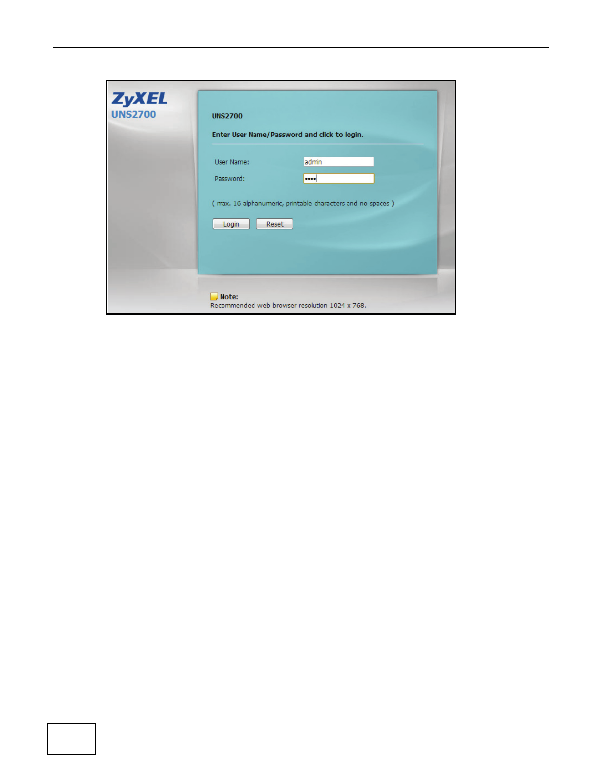
Figure 1 Admin Account Login
To access the Web UI, type the default user name admin and password 1234. The home page
displays when the correct password has been entered.
12
UNS Series User’s Guide
Page 15
3.1 Overview
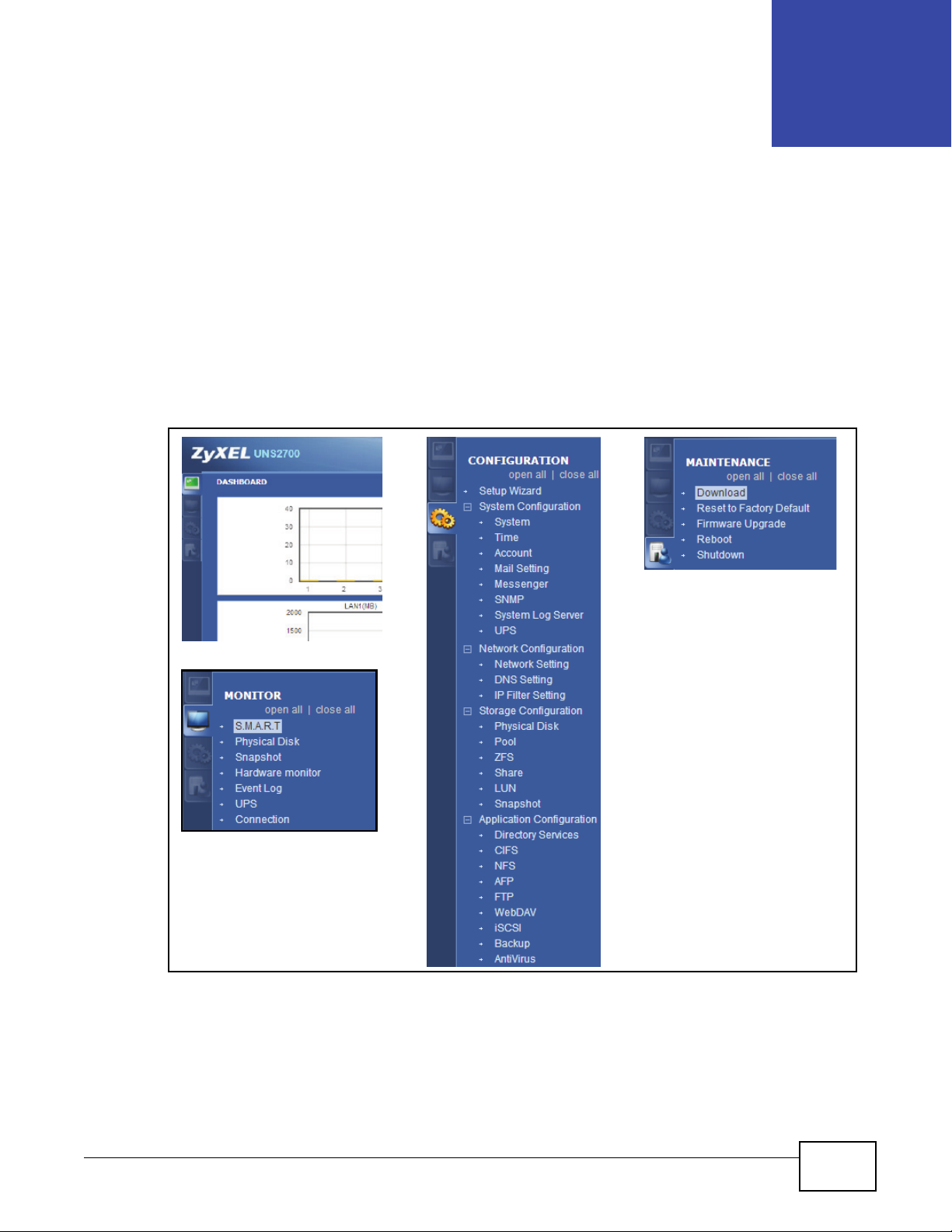
Use the sub-menus on the navigation panel to configure UNS Series feature.
Choose the functions from the Menu Bar on the left side of the window to make any configuration
changes.
Figure 2 Navigation Panel
CHAPTER 3
Navigation Panel
UNS Series User’s Guide 13
Page 16
Chapter 3 Navigation Panel
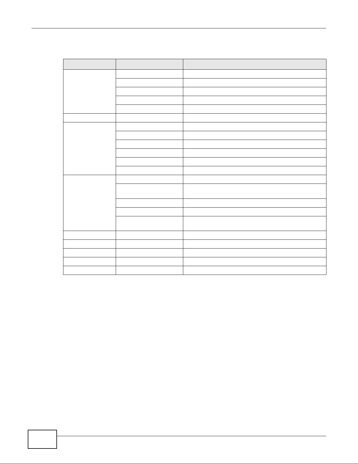
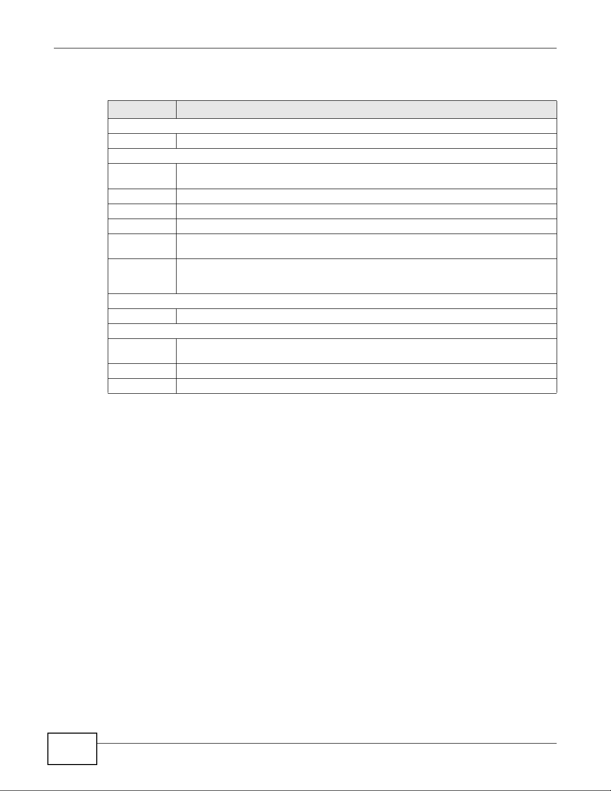
The following table describes the hierarchy of the Web UI.
Table 1 Navigation Panel
MENU BAR LEVEL 1 LEVEL 2
DASHBOARD Logout
MONITOR S.M.A.R.T
CONFIGURATION Setup Wizard
MAINTENANCE Download Download MIB file / Download System Information
About
Help
Refresh Intervals
Refresh Now
Physical Disk
Snapshot
Hardware Monitor
Event Log
UPS
Connection
System Configuration System / Time / Account / Mail Setting / Messenger /SNMP
/ System Log Server / UPS
Network Configuration Network Settings / DNS Settings / IP Filter Setting
Storage Configuration Physical Disk / Pool / ZFS / Share / Snapshot
Application Configuration Directory Services / CIFS / NFS / AFP / FTP / WebDAV /
ISCSI / Backup / Antivirus
Reset to Factory Default
Firmware Upgrade
Reboot
Shutdown
3.2 Dashboard
The Dashboard interface provides an overview of the device’s overall status.
14
UNS Series User’s Guide
Page 17

Figure 3 Dashboard
Chapter 3 Navigation Panel
The following table describes the items on this screen.
Table 2 Dashboard
ITEM DESCRIPTION
DASHBOARD
Disk
Throughput
(KB)
LAN1 (MB) Displays the current data throughput for LAN1.
LAN2 (MB) Displays the current data throughput for LAN2.
UNS Series User’s Guide
Displays the current disk throughput.
15
Page 18

Chapter 3 Navigation Panel
Table 2 Dashboard (continued)
ITEM DESCRIPTION
LAN3 (MB) Displays the current data throughput for LAN3.
LAN4 (MB) Displays the current data throughput for LAN4.
Device Information
System Name Displays the name of the device.
Model Name Displays the model number of the device.
Serial Number Shows the serial number of the device.
Firmware
Version
System Status
System Up
Time
Current Date/
Time
System Resource
-CPU
Usage
-Memory
Usage
Temperature
Item Shows the name of each storage component.
Value Displays the current temperature of each component.
Status Displays the current status.
Power Supply
Item Shows the name of each storage component.
Value Displays the current value.
Status Displays the current status.
Cooling
Item Shows the name of each storage component.
Value Shows the Fan speeds.
Status Displays the current status.
Service Status
Directory
Services
CIFS Displays the status of the service: Enabled or Disabled.
NFS Displays the status of the service: Enabled or Disabled.
AFP Displays the status of the service: Enabled or Disabled.
FTP Displays the status of the service: Enabled or Disabled.
webDAV Displays the status of the service: Enabled or Disabled.
Event Log
Type Displays the message type.
Time Displays the time when receiving the message.
Content A brief explanation of the message.
Pool Status
Displays the current firmware version.
Displays how long the system has been up and running.
Shows the current date and time.
Displays the current status of CPU usage.
Displays the current status of Memory usage.
Displays the type of directory services that is being configured for the current domain
security.
16
UNS Series User’s Guide
Page 19

Chapter 3 Navigation Panel
Table 2 Dashboard (continued)
ITEM DESCRIPTION
Dedup usage Displays the Dedup usage.
Name Shows the name of a storage pool.
Status Shows the status of a storage pool.
Total (GB) Displays the capacity of a storage.
Used (GB) Displays the amount of used disk space.
Free (GB) Displays the amount of available disk space.
You can specify Refresh Interval at the top right corner or click Refresh Now to manually update
the system status.
Figure 4 Dashboard > Refresh Now
The following table describes the items on the screen.
Table 3 Dashboard > Refresh Now
ITEM DESCRIPTION
Refresh Interval
Drop-down
menu
Refresh Now Click Refresh Now to manually update the system status.
You can specify how long the system will report the system status.
UNS Series User’s Guide
17
Page 20

Chapter 3 Navigation Panel
18
UNS Series User’s Guide
Page 21

4.1 Overview
This chapter shows you how to use the UNS Series’ various features.
4.2 Usage Scenario
Assume that an IT manager of an SMB company with 200 employees buys a device. How can the IT
manager deploy the UNS Series to meet everyone’s needs? There may be different departments
each with specific needs such as running different operating system platforms (Windows, Mac,
Linux), or provisioning storage space for different application servers to make sure business critical
applications run without interruption.
CHAPTER 4
Getting Started
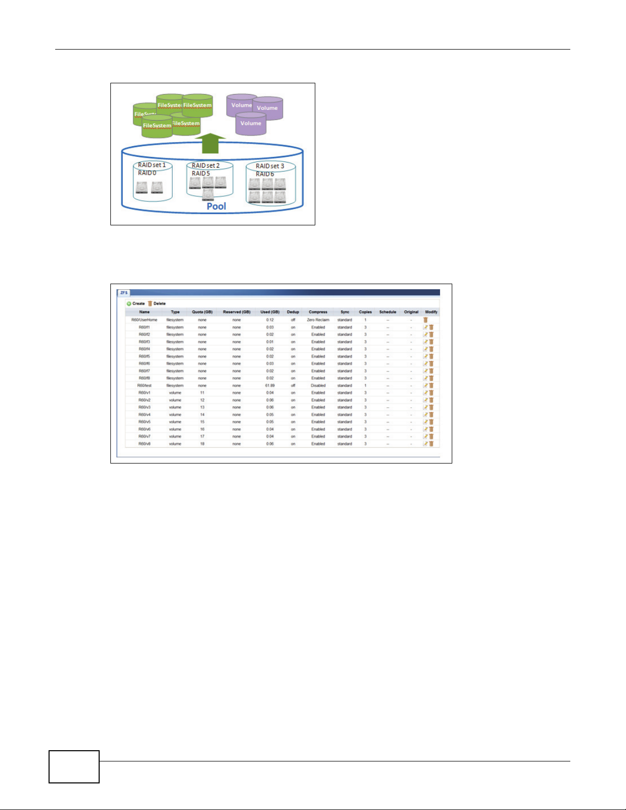
4.3 Creating a Storage Pool
Before configuring the UNS system, you must install hard drives and create storage space for the
services and system setup process. A storage pool consists of one or more RAID sets. Pool size is
expanded by adding extra RAID sets which can be done on demand without stopping data services.
To create storage pools, file systems, or iSCSI volumes on the UNS system, click Configuration >
Storage Configuration.
Figure 5 Configuration > Storage Configuration
To set up file sharing, create a file system from the storage pool and create folders and shares
within the file system.
To set up block-level access, create an iSCSI volume from the storage pool.
Enterprise level functions such as thin provisioning, deduplication, and compression serve to
maximize the storage efficiency of UNS Series system.
UNS Series User’s Guide 19
Page 22
Chapter 4 Getting Started
Figure 6 UNS Series Storage Configuration
Click Configuration > Storage Configuration > ZFS to create the file systems and iSCSI
volumes.
Figure 7 Configuration > Storage Configuration > ZFS
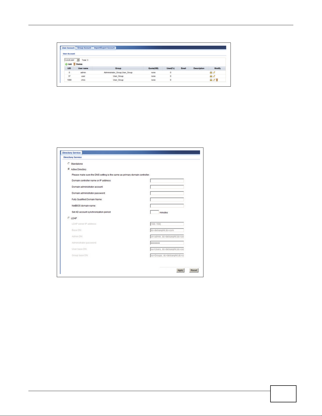
4.4 Configuring a User Account
UNS Series supports both local user accounts and domain accounts. All user and group account
information is displayed in the User Account and Group Account screens. An import/export function
is available for local accounts and is located on the Import/Export Account screen. The import/
export function is particularly useful for batch user account jobs.
Click Configuration -> System Configuration -> Account to view the User Account screen.
Click Configuration -> System Configuration -> Account > Group Account to view the Group
Account screen.
Click Configuration -> System Configuration -> Account > Import/Export Account to view
the Import/Export Account screen.
20
UNS Series User’s Guide
Page 23
Chapter 4 Getting Started
Figure 8 Configuration > System Configuration > Account
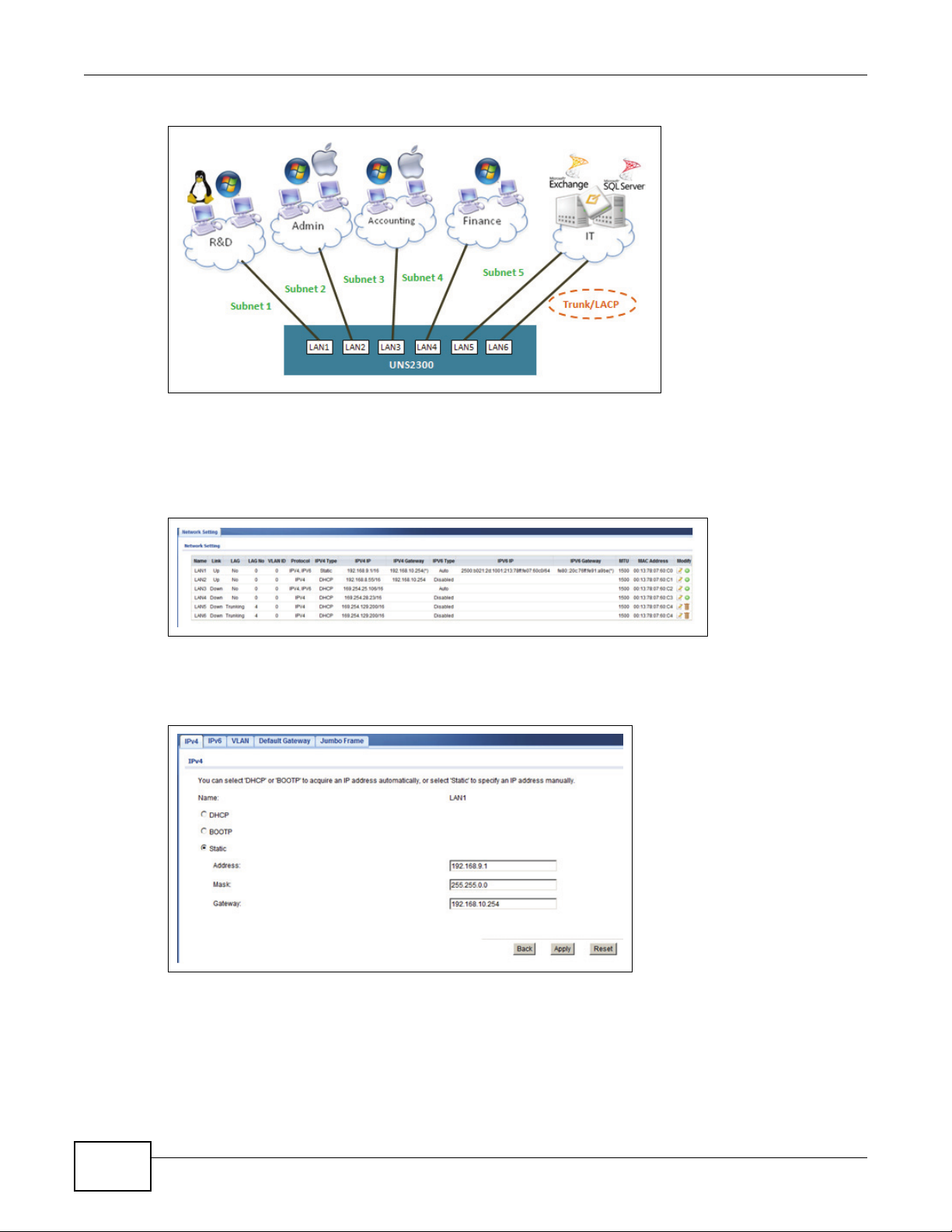
An IT manager can choose the type of account management that fits their IT infrastructure. The
UNS Series supports stand-alone, Active Directory, and LDAP services. The UNS Series easily
integrate with AD/LDAP servers to streamline the account setup process. All the IT manager needs
to do is provide the correct login data to join the domain.
To access directory services, click Configuration > Application Configuration > Directory
Services.
Figure 9 Configuration > Application Configuration > Directory Services
4.5 Configuring Network Settings
The UNS Series supports gigabyte ethernet ports with multi-home setting. All ports can have
different subnet settings to accommodate a company’s IT infrastructure. If extra bandwidth is
needed, link aggregation is supported with three different modes to choose from. All major data
services such as CIFS, NFS, AFP, FTP, WebDAV, and iSCSI are supported. Services can be assigned
on all network ports or can be dedicated to individual ports for each department for easy
management.
UNS Series User’s Guide
21
Page 24
Chapter 4 Getting Started
Figure 10 Configuring a Network
There are a variety of options available to an IT manager to configure a network for any scenario.
To view network port settings, click Configuration > Network Configuration > Network
Setting.
Figure 11 Configuration > Network Configuration > Network Setting
To configure network settings for a port, click Configuration > Network Configuration >
Network Setting > (Modify) Edit.
Figure 12 Configuration > Network Configuration > Network Setting > (Modify) Edit
4.6 All About Sharing
After the storage pool is ready and user accounts have been created, you can assign the access
control list to the different shares. The UNS Series provides a straight forward Web Configurator to
22
UNS Series User’s Guide
Page 25

Chapter 4 Getting Started
facilitate the process of setting access control. The Web Configurator gives an IT manager the
maximum control over allowing who can access what data. It also makes sure data security and
confidentiality are maintained using the highest level of security with minimum management
efforts.
To view folders and shares, click Configuration -> Storage Configuration -> Share.
Figure 13 Configuration -> Storage Configuration -> Share
To adjust access control settings for an entry, click Configuration -> Storage Configuration ->
Share > (Modify) Edit.
Figure 14 Configuration -> Storage Configuration -> Share > (Modify) Edit
4.7 Conclusion
The UNS Series is the ideal unified storage system for small to medium-sized companies. It
provides both file access and block access at the same time to meet all kinds of deployment needs.
IT mangers can use thin provisioning to create multiple types of file systems and iSCSI volumes to
achieve greater storage efficiency. Data is protected by RAID and the ZFS file system making sure
of end-to-end data consistency at all times. Extra data protection can be added using snapshot and
remote replication. The UNS Series is the ultimate storage solution for your company.
UNS Series User’s Guide
23
Page 26

Chapter 4 Getting Started
24
UNS Series User’s Guide
Page 27
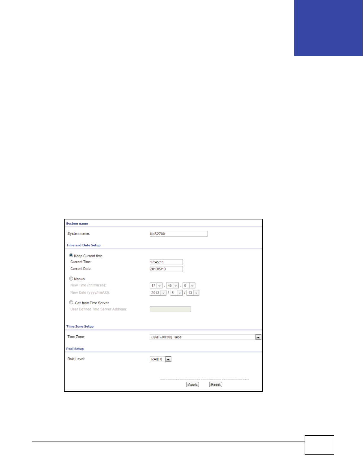
4.1 Overview
The Setup Wizard section allows you to initially configure the system name, time, time zone and
RAID pool levels.
4.2 System Wizard
Click Configuration > Setup Wizard to display the following screen.
The Setup Wizard function is only available when all disks are marked as FreeDisk. In the event
that a disk is in use, the Setup Wizard function directs you to the Physical Disk screen.
CHAPTER 4
Setup Wizard
Figure 15 Configuration > Setup Wizard
UNS Series User’s Guide 25
Page 28
Chapter 4 Setup Wizard
The following table describes the items on this screen.
Table 4 Configuration > Setup Wizard
ITEM DESCRIPTION
System name
System name Enter the system name for your device.
Time and Date Setup
Keep Current
time
Current Time Displays the current time setting based on your computer system.
Current Date Displays the current date setting based on your computer system.
Manual Select Manual to set the current time and date from the New Time and New Date fields.
Get from Time
Server
User Defined
Time Server
Address
Time Zone Setup
Time Zone Click the drop-down menu to select a time zone.
Pool Setup
Raid Level Click the drop-down menu to select a RAID setting: RAID 0, RAID 1, RAID 5, RAID 6,
Apply Click Apply to confirm the changes.
Reset Click Reset to discard the changes.
Select Keep Current time to set the current time and date based on your computer
system’s setting.
Select Get from Timer Server to synchronize from a defined Time Server Address.
Enter a Time Server Address to automatically set the time and date.
RAID 10, RAID 50, or RAID 60.
26
UNS Series User’s Guide
Page 29

PART II
Technical Reference
27
Page 30

28
Page 31

6.1 Overview
The Monitor menu consists of the following options: S.M.A.R.T, Physical Disk, Snapshot,
Hardware Monitor, Event Log, UPS, and Connection.
6.1.1 S.M.A.R.T
S.M.A.R.T. (Self-Monitoring Analysis and Reporting Technology) is a hard drive diagnostic tool which
delivers warning messages when drives are approaching failures. The S.M.A.R.T. option provides
users a chance to take actions before a possible drive failure.
S.M.A.R.T. measures attributes which are specific parameters of various parts of a hard drive and
analyzes the health status of hard drives constantly. The notice is given when the possible hard
drive failure occurs, which allows you to back up your data or replace your drives in advance.
CHAPTER 6
Monitor
The numbers displayed are real-time values. The number within parenthesis is the threshold value.
The threshold values vary from hard drive vendor to hard drive vendor; please refer to hard drive
vendors' specification for details.
S.M.A.R.T. technology only supports SATA drives.
Click Monitor > S.M.A.R.T to display the following screen.
Figure 16 Monitor > S.M.A.R.T
The following table describes the items on this screen.
Table 5 Monitor > S.M.A.R.T
ITEM DESCRIPTION
S.M.A.R.T
Slot No. Indicates slot location.
UNS Series User’s Guide 29
Page 32

Chapter 6 Monitor
Table 5 Monitor > S.M.A.R.T (continued)
ITEM DESCRIPTION
HDD Type Indicates the hard disk type.
Read Error
Rate
Spin Up Time The amount of time required for the drive platters to get up to full operational speed.
Reallocated
Sector Count
Seek Error
Rate
Spin Up
Retries
Calibration
Retries
Temperature
(°C)
6.1.2 Physical Disk
Displays the error rate when reading the disk.
Indicated the reallocated sectors count. Read/write/verification errors on a hard drive are
marked as reallocated, the data is transferred to a special reserved area (spare area).
Indicates the rate of errors on the magnetic head.
Indicates the number of spindle spin ups.
Indicates the recalibration count requested due to due to an unsuccessful previous attempt.
Shows the temperature of the hard disk in degrees Celsius.
The Physical disk option gives you the hard drive status. Click Monitor > Physical Disk to
display the following screen.
Figure 17 Monitor > Physical Disk
The following table describes the items on this screen.
Table 6 Monitor > Physical Disk
ITEM DESCRIPTION
Slot The position of a hard drive. The button next to the number of slot shows the
functions which can be executed.
Size (GB) Hard drive capacity. The unit can be displayed in GB or MB.
Pool Name Pool name.
Status The status of the hard drive:
30
• Online: the hard drive is online.
• Rebuilding: the hard drive is being rebuilt.
• Degraded: one of the RAID set is in degraded mode.
• Failed: one of the RAID set is in failed mode.
• Importing: the system is loading data from the disks, which means the pool is
not ready for use yet.
UNS Series User’s Guide
Page 33

Table 6 Monitor > Physical Disk (continued)
ITEM DESCRIPTION
Health The health of the hard drive:
• Good: indicates that the hard drive is healthy.
• Failed: indicates that the hard drive has failed.
• Error alert: S.M.A.R.T. error alert.
• Read errors: indicates that the hard drive has unrecoverable read errors.
• Reserved: One of the RAID member disks contains RAID group and pool
information. If the original RAID group and pool information can't be found,
either you have put this disk into its original slot or have set this disk as a free
disk.
SMARTCTL The SMART of the hard drive:
• Unknown: the SMART of the hard drive is unknown.
• NoError: the SMART of the hard drive has no error.
• HasError: the SMART of the hard drive has errors.
Usage The usage of the hard drive:
• RAID disk: The hard drive is set to a RAID group.
• Free disk: The hard drive contains free hard disk space.
• Dedicated spare: The hard drive is set as a dedicated spare of a pool.
SSD Solid-state drive (SSD).
Vendor Displays hard drive vendor.
Serial Displays hard drive serial number.
Rate Hard drive rate:
Chapter 6 Monitor
6.1.3 Snapshot
All point-in-time snapshots at which you have created are displayed here. Click Monitor >
Snapshot to display the following screen.
Figure 18 Monitor > Snapshot
The following table describes the items on this screen.
Table 7 Monitor > Snapshot
ITEM DESCRIPTION
Snapshot
Filter Select All or specific snapshots created for individual shares from the drop-down
Name The name of a snapshot.
Used (MB) Indicates the amount of used snapshot space.
•SATA 6Gb/s
•SATA 3Gb/s
• SATA 1.5Gb/s
menu.
UNS Series User’s Guide
31
Page 34

Chapter 6 Monitor
Table 7 Monitor > Snapshot
ITEM DESCRIPTION
Refer (GB) Indicates the referred capacity of the file system or the volume.
Created time Indicates the time in which the snapshot was created.
6.1.4 Hardware Monitor
The Hardware Monitor option displays the information of current voltages and temperatures.
Click Monitor > Hardware Monitor to display the following screen.
Figure 19 Monitor > Hardware Monitor
The following table describes the items on this screen.
Table 8 Monitor > Hardware Monitor
ITEM DESCRIPTION
Voltage
Item Indicates the specific voltage meter on the device.
Value Indicates the current voltage including the minimum and maximum values.
Status Indicates the current health status of the voltage item.
6.1.5 Event Log
The Event Log option provides a log or event messages. By default, the log event types such as
INFO, WARNING, and ERROR are all selected. Click Monitor > Event Log to display the following
screen.
32
UNS Series User’s Guide
Page 35

Figure 20 Monitor > Event Log
The following table describes the labels on this screen.
Table 9 Monitor > Event Log
LABEL DESCRIPTION
Event Log
Clear Click the Clear button to clear all event logs.
Download Click the Download button to download the log file.
Filter
Information Select to list Information events (default: selected).
Warning Select to list Warning events (default: selected).
Error Select to list Error events (default: selected).
Type Displays the log event type.
Time Displays the time the event occurred.
Content Provides a brief explanation of the event.
First Click First to navigate to the first page.
Last Click Last to navigate to the last page.
Chapter 6 Monitor
The event log is displayed in reverse order which means the latest event log is on the first / top of
the page.
To clear the event log, click Clear and confirm at the prompt.
Figure 21 Monitor > Event Log > Clear
UNS Series User’s Guide
33
Page 36

Chapter 6 Monitor
6.1.6 UPS
Click Monitor > UPS to display the following screen.
Figure 22 Monitor > UPS
The following table describes the labels on this screen.
Table 10 Monitor > UPS
LABEL DESCRIPTION
UPS
UPS type Indicates the UPS type.
Shutdown
Battery Level
Shutdown
Delay
Shutdown UPS Indicates if the shutdown function is disabled or enabled.
Status Indicates the current status of the UPS.
Battery Level Displays the battery level charge (percentage).
6.1.7 Connection
Click Monitor > Connection to display the following screen.
Figure 23 Monitor > Connection
Indicates the battery level percentage before the device initiates a graceful shutdown.
Indicates the delay time before a graceful shutdown occurs.
34
UNS Series User’s Guide
Page 37

The following table describes the labels on this screen.
Tabl e 11 Monitor > Connection
LABEL DESCRIPTION
Connection
Protocol Displays the type of protocol assigned to this connection.
User Displays the user profile currently associated with this connection.
Client Displays the type of client.
Server Indicates the name of the server associated with this connection.
Chapter 6 Monitor
UNS Series User’s Guide
35
Page 38

Chapter 6 Monitor
36
UNS Series User’s Guide
Page 39

7.1 Overview
This section provides information for System in System Configuration.
7.2 System
The System option is used to setup the system name, system indication, buzzer and auto
shutdown. The default system name is composed of the model name and its serial number. Click
Configuration > System Configuration > System to display the following screen.
Figure 24 Configuration > System Configuration > System
CHAPTER 7
System
The following table describes the items on this screen.
Table 12 Configuration > System Configuration > System
ITEM DESCRIPTION
System name
System name To c hange th e System name, place the mouse pointer inside the name box, highlight the
old name and type in a new one.
Buzzer
UNS Series User’s Guide 37
Page 40

Chapter 7 System
Table 12 Configuration > System Configuration > System
ITEM DESCRIPTION
Buzzer Select Enable or Disable to configure the Buzzer function. When enabled, the Buzzer
Auto shutdown Select Enable or Disable to configure Auto Shutdown.
Apply Click Apply to save the changes.
Reset Click Reset to discard the changes.
function provides and audible alert when the device detects a system fault.
An automatic shut down occurs when the system internal power or temperature readings
exceed normal levels.
38
UNS Series User’s Guide
Page 41

8.1 Overview
This chapter provides information for Time in System Configuration.
8.2 Time Setting
The Time option is used to setup the system time and NTP (Network Time Protocol) server setting.
Click Configuration > System Configuration > Time to display the following screen.
Figure 25 Configuration > System Configuration > Time
CHAPTER 8
Time
The following table describes the items on this screen.
Table 13 Configuration > System Configuration > Time
LABEL DESCRIPTION
Current Time and Date
Current Time: Display current time.
Current Date: Display current date.
Time and Date Setup
Manual Select the Manual radio button to change the date and time manually.
UNS Series User’s Guide 39
Page 42

Chapter 8 Time
Table 13 Configuration > System Configuration > Time (continued)
LABEL DESCRIPTION
New Time
(hh:mm:ss)
New Date
(yyyy/mm/dd)
Get from Time
Server
User Defined
Time Server
Address
Time Zone Setup
Time Zone: Select your time zone from the drop-down menu.
Apply Click Apply to save the changes.
Reset Click Reset to discard the changes.
Select hours, minutes, and seconds from the drop-down menu.
Select year, month, and date from the drop-down menu.
Select the Get from Time Server radio button if you want to synchronize the time with a
NTP server.
Enter the IP address of the NTP server.
40
UNS Series User’s Guide
Page 43

9.1 Overview
The chapter covers network and system storage management. It also discusses various web
applications and services.
9.2 User Account
The Account option offers functions to manage local user accounts such as add, delete, edit,
change password or view the status of the users. Local user accounts and domain user accounts are
displayed separately by selecting the drop down list.
Domain user accounts are only for display purpose. You cannot edit domain account or change the
password of domain accounts. Click Configuration > System Configuration > Account to
display the following screen.
CHAPTER 9
Account
Figure 26 Configuration > System Configuration > Account
The following table describes the labels on this screen.
Table 14 Configuration > System Configuration > Account
ITEM DESCRIPTION
Local user Click to select Local or Domain users.
UID Displays the user ID.
User name Displays the account profile name.
Group Displays the group associated with the account profile.
Quota (GB) Displays the allocated space for the user.
Used (%) Displays the amount of used (percentage) space from the allocated quota.
Email Displays the user's designated email.
Description Displays the description given to this user account.
Modify
Change Password Click to change the name of the selected user’s account password.
UNS Series User’s Guide 41
Page 44

Chapter 9 Account
Note: When connecting a user’s home directory (Windows) share, the network drive
capacity displays the free space of the storage pool and not the user quota size.
The home directory is created using the thin provisioning function resulting in the
larger free space capacity. However, the user’s share is still limited to the defined
user quota and not the capacity designated by thin provisioning.
9.2.1 The Change Password Screen
Click Configuration > System Configuration > Account > Change password to display the
following screen.
Figure 27 Configuration > System Configuration > Account > Change password
The following table describes the labels on this screen.
Table 15 Configuration > System Configuration > Account > Change password
ITEM DESCRIPTION
Change Password
Name Displays the account profile name.
New Password Enter the new password for this account.
Retype Password Enter the new password again for verification.
Back Click Back to go to the previous screen.
Apply Click Apply to confirm the changes.
Reset Click Reset to discard the changes.
9.3 Group Account
The Group Account option offers functions to manage local groups such as add, delete, edit, or
view the status of the groups. Local groups and domain groups are displayed separately by
selecting the drop down list. Click Configuration > System Configuration > Account > Group
Account to display the following screen.
42
UNS Series User’s Guide
Page 45

Figure 28 Configuration > System Configuration > Account > Group Account
The following table describes the labels on this screen.
Table 16 Configuration > System Configuration > Account > Group Account
LABELS DESCRIPTION
GID Displays the group ID (user assigned range 1000 ~ 60000).
Group name Displays the group name for the GID.
#User Displays the number of users belonging to this group.
Description Displays a description for this group.
9.4 Import/Export Account
Chapter 9 Account
The Import/Export function allows you to import or export user account settings to or from an
external file. Click Configuration > System Configuration > Account > Import/Export
Account to display the following screen.
Figure 29 Configuration > System Configuration > Account > Import/Export Account
The following table describes the labels on this screen.
Table 17 Configuration > System Configuration > Account > Import/Export Account
ITEM DESCRIPTION
Export
Export account setting
file
Import
Overwrite duplicated
account
File Path Displays the file path of the selected document.
Browse Click Browse to browse for an account file to import.
Click Export to export the user account settings to a text file.
Select this to overwrite a pre-existing account.
UNS Series User’s Guide
43
Page 46

Chapter 9 Account
ITEM DESCRIPTION
Apply Click Apply to save the changes.
Reset Click Reset to discard the changes.
44
UNS Series User’s Guide
Page 47

10.1 Overview
This chapter provides information on the Mail Setting screens in Configuration. The Mail Setting
helps you to configure mail server settings and mail event logs.
10.2 Mail Setting
The Mail setting option is used to enter up to three mail addresses to receive event notifications.
Fill in the necessary fields and click Send test mail to test the configuration. Some mail servers
check the Mail-from address and need the SMTP relay setting for authentication.
You can set the event login levels to receive (default: Warning and Error). Please make sure that
the DNS server IP has been setup correctly (Configuration > Network Configuration > DNS
Setting), so the event notification mail can be sent successfully. Click Configuration > System
Configuration > Mail Setting to display the following screen.
CHAPTER 10
Mail Setting
UNS Series User’s Guide 45
Page 48

Chapter 10 Mail Setting
Figure 30 Configuration > System Configuration > Mail Setting
The following table describes the items on this screen.
Table 18 Configuration > System Configuration > Mail Setting
ITEM DESCRIPTION
Mail Setting
Mail-from
address
Mail-to
address 1
Information,
Warning, Error
Mail-to
address 2
Information,
Warning, Error
Mail-to
address 3
Information,
Warning, Error
SMTP relay Select SMTP relay if you want to send, receive, or route e-mail across a network.
To change t h e Mail-from address, place the mouse pointer inside the name box, highlight
the old name and type in a new one.
Enter your first mail address.
Select event Login levels.
Enter your second mail address.
Select event Login levels.
Enter your third mail address.
Select event Login levels.
46
UNS Series User’s Guide
Page 49

Chapter 10 Mail Setting
Table 18 Configuration > System Configuration > Mail Setting
ITEM DESCRIPTION
SMTP server Enter the IP address or DNS name of the SMTP server.
No
authentication
Log on using Select Log on using radio button if the SMTP server requires authentication.
Account Enter your account name.
Password Enter your password
Enable secure
connection
(SSL)
Send test mail Click Send test mail to send test email.
Apply Click Apply to save the changes.
Reset Click Reset to discard the changes.
Select No authentication radio button if the SMTP server does not require authentication.
Enable this check box for secure message transmission.
UNS Series User’s Guide
47
Page 50

Chapter 10 Mail Setting
48
UNS Series User’s Guide
Page 51

11.1 Overview
This chapter provides information on the Messenger setup screens in Configuration. The Messenger
screen helps you to setup messenger services for designated accounts and event log reporting.
11.2 Messenger
The Messenger option is used to net send and transmit user messages between computers, up to
three accounts. The Messenger service must first be enabled on your server side. Setting
configuration also includes even log notification. Click Configuration > System Configuration >
Messenger to display the following screen.
CHAPTER 11
Messenger
Figure 31 Configuration > System Configuration > Messenger
The following table describes the items on this screen.
Table 19 Configuration > System Configuration > Messenger
ITEM DESCRIPTION
Messenger
Messenger IP/
computer
name 1
Messenger IP/
computer
name 2
Messenger IP/
computer
name 3
Enter the first Messenger IP / computer name.
Enter the second Messenger IP / computer name.
Enter the third Messenger IP / computer name.
UNS Series User’s Guide 49
Page 52

Chapter 11 Messenger
Table 19 Configuration > System Configuration > Messenger (continued)
ITEM DESCRIPTION
Information,
Warning, Error
Apply Click Apply to save the changes.
Reset Click Reset to discard the changes.
Click to select the event login levels.
50
UNS Series User’s Guide
Page 53

12.1 Overview
This section provides information for Simple Network Management Protocol (SNMP) to manage
network devices.
12.2 SNMP
The SNMP option is used to setup SNMP traps (for SNMP alerts). This feature allows up to three
SNMP trap addresses. By default, the community setting is public. You can select alert levels which
you want to receive. The default setting only includes WARNING and ERROR event logs. There are
many SNMP tools available on the internet.
CHAPTER 12
SNMP
•SNMPc: http://www.snmpc.com/
•Net-SNMP: http://net-snmp.sourceforge.net/
Click Configuration > System Configuration > SNMP to display the following screen.
Figure 32 Configuration > System Configuration > SNMP
The following table describes the labels on this screen.
Table 20 Configuration > System Configuration > SNMP
LABELS DESCRIPTIONS
SNMP
SNMP trap
address 1
Enter the first SNMP trap address.
UNS Series User’s Guide 51
Page 54

Chapter 12 SNMP
Table 20 Configuration > System Configuration > SNMP (continued)
LABELS DESCRIPTIONS
SNMP trap
address 2
Enter the second SNMP trap address.
SNMP trap
address 3
Community Enter the community string (password) used to authenticate messages between
Information,
Warning, Error
Apply Click Apply button to save the changes.
Reset Click Reset button to discard the changes.
Enter the third SNMP trap address.
communities.
Click to select the event login levels.
52
UNS Series User’s Guide
Page 55

13.1 Overview
This section introduces the System Log Server (Syslog), a standard for computer data logging.
Syslog services allows you to designate which system messages to manage your system and
security auditing. General informational, analysis, and debugging messages can also be included.
13.2 System Log Server
The System Log Server option is used to setup alerts via the Syslog protocol. Fill in the necessary
fields for Syslog service. The default port is 514. Set an alert level to You can choose an alert level
which you want to receive. The default setting only includes WARNING and ERROR event logs.
CHAPTER 13
System Log Server
The following are available Syslog server tools. The list is provided as a reference only.
There are some Syslog server tools available on the internet for Windows. Most UNIX systems have
a built-in Syslog daemon.
•WinSyslog: http://www.winsyslog.com/
• Kiwi Syslog Daemon: http://www.kiwisyslog.com/
Click Configuration > System Configuration > System Log Server to display the following
screen.
Figure 33 Configuration > System Configuration > System Log Server
The following table describes the items on this screen.
UNS Series User’s Guide 53
Page 56

Chapter 13 System Log Server
Table 21 Configuration > System Configuration > System Log Server
ITEM DESCRIPTION
System Log Server
Server IP/
hostname
UDP port By default, the UDP port is 514
Faci lity Select an account from the drop-down menu.
Information,
Warning, Error
Apply Click Apply to save the changes.
Reset Click Reset to discard the changes.
Enter the IP address / hostname of the System Log Server.
Click to select the type of event login information to report.
54
UNS Series User’s Guide
Page 57

14.1 Overview
This chapter provides information for the Uninterruptible Power Supply (UPS) service in System
Configuration.
14.2 UPS
Click Configuration > System Configuration > UPS to display the following screen.
Figure 34 Configuration > System Configuration > UPS
CHAPTER 14
UPS
The following table describes the items on this screen.
Table 22 Table Configuration > System Configuration > UPS
ITEM DESCRIPTION
UPS
UPS type Use this to select the UPS type: None, Smart-UPS, or Megatec.
None: no UPS available
Megatec-UPS: a Megatec supported device
IP Address Enter the IP Address of the UPS type.
Community Enter the SNMP community string.
UNS Series User’s Guide 55
Page 58

Chapter 14 UPS
Table 22 Table Configuration > System Configuration > UPS (continued)
ITEM DESCRIPTION
Shutdown
Battery Level
(%)
Shutdown
Delay (s)
Shutdown UPS Use this to enable an automatic UPS shutdown after a successful system shutdown during a
Apply Click Apply to save the changes.
Reset Click Reset to discard the changes.
Displays the current battery level. A setting level of zero initiates function shutdown.
Displays the delay timer before shutdown. In the event of power failure, the system will
attempt a recovery within the allocated delay period, otherwise it initiates a shutdown
procedure. Setting of zero disables the function.
power failure. Once power is restored, the UPS function triggers a system power up function.
56
UNS Series User’s Guide
Page 59

15.1 Overview
This chapter provides information for the network settings in Configuration.
15.2 Network Setting Screen
The Network Setting option is mainly used for accessing the LAN1 port and LAN ports. You can
use this option to configure IP addresses for these network ports. The UNS Series includes the
following network port configuration:
• UNS Series: 1 x GbE LAN1 port + 2 x 10GbE port + 1 x GbE port per controller.
CHAPTER 15
Network Setting
Each port must be assigned its own IP address--multi-homed mode, or in present link aggregation
/ trunking mode configurations. Multiple LAN ports are set up in link aggregation mode or trunk
mode allowing all ports to share the same IP address. Click Configuration > Network
Configuration > Network Setting to display the following screen.
Figure 35 Configuration > Network Configuration > Network Setting
The following table describes the labels on this screen.
Table 23 Configuration > Network Configuration > Network Setting
LABELS DESCRIPTIONS
Name Display the LAN1 port or LAN ports.
Link Display the network link status:
• Green Light: the link is up and running.
• Red Light: the link is down.
LAG Display the link aggregation status.
LAG No Display the link aggregation number.
VLAN ID Display the VLAN number.
Protocol Display IPv4 or IPv6.
UNS Series User’s Guide 57
Page 60

Chapter 15 Network Setting
Table 23 Configuration > Network Configuration > Network Setting (continued)
LABELS DESCRIPTIONS
IPV4 Type IPv4 address mode:
IPV4 IP IPv4 addresses.
IPV4 Gateway Gateway that uses IPv4 address.
IPV6 Type IPv6 address mode:
IPV6 IP IPv6 addresses.
IPV6 Gateway Gateway that uses IPv6 address.
MTU Maximum Transmission Unit. By default, MTU is 1500
MAC Address Display MAC addresses.
Modify
Edit Click Edit to configure the following settings: IPv4, IPv6, VLAN, Default Gateway
Create Link Aggregation Click Create Link Aggregation to combine multiple connections to create a
• Static: means static IP addresses.
• DHCP: means dynamic assigned IP addresses.
• Static: static address.
• Auto: RA (router advertisement calculated address.)
•DHCP: DHCPv6 assigned address.
and Jumbo Frame.
parallel bond.
The LAN1 port is the network port for downloading QCentral software via HTTP. The port does not
support the WebDAV service or link aggregation to other LAN ports--GbE and 10GbE LAN ports
cannot be aggregated.
15.2.1 The Network Setting Edit Screen
The Edit function allows you to modify the properties of each network interface. Click the
Configuration > Network Configuration > Network Setting > Edit to begin the process.
15.2.1.1 The Edit IPv4 Screen
Click Configuration > Network Configuration > Network Setting > Edit > IPv4 to display the
following screen.
58
UNS Series User’s Guide
Page 61

Chapter 15 Network Setting
Figure 36 Configuration > Network Configuration > Network Setting > Edit > IPv4
The following table describes the items on this screen.
Table 24 Configuration > Network Configuration > Network Setting > Edit > IPv4
ITEM DESCRIPTION
IPV4 Setting
Name Display the name of a network interface.
DHCP By default, DHCP is selected.
BOOTP Select BOOTP radio button to acquire an IP address automatically.
Static Select Static radio button to specify an IP address manually.
Address Enter the new IP address for the network setting.
Mask Enter the new mask address for the network setting.
Gateway Enter the new gateway address for the network setting.
Back Click Back to go to the previous screen.
Apply Click Apply to save the changes.
Reset Click Reset to change the screen to the default settings.
15.2.2 The Edit IPv6 Screen
Click Configuration > Network Configuration > Network Setting > Edit > IPv6 to display the
following screen.
UNS Series User’s Guide
59
Page 62

Chapter 15 Network Setting
Figure 37 Configuration > Network Configuration > Network Setting > Edit > IPv6
The following table describes the items on this screen.
Table 25 Configuration > Network Configuration > Network Setting > Edit > IPv6
ITEM DESCRIPTION
IPv6
Enable IPv6 Enable this check box to use the IPv6 feature.
Name Display the name of a network interface.
Automatic Select Automatic to let the system manage IPv6 address allocation.
DHCP Select DHCP radio button to acquire an IP address dynamically.
Static Select Static to specify an IP address manually.
IPv6
Address
Prefix
Length
Gateway Enter the new gateway address for the network setting.
Back Click Back to go to the previous screen.
Apply Click Apply to save the changes.
Reset Click Reset to change the screen to the default settings.
Enter the new IPv6 address for the network setting.
Enter the new subnet mask for the network setting.
15.2.3 The Edit VLAN Screen
60
A Virtual LAN (VLAN) is a logical grouping mechanism implemented on network switches. Each
VLAN is a collection of switching ports that comprises of a single broadcast domain in order to
optimize the amount of network traffic.
Please refer to your network switch’s user guide for more information on how to create a VLAN
environment. Most of the work is done on the switches. Make sure that your iSCSI port's VLAN ID
matches the VLAN ID of the switch. If your network environment supports VLAN, you can click Set
VLAN ID to change the settings. If network ports are assigned with VLAN ID before creating link
UNS Series User’s Guide
Page 63

Chapter 15 Network Setting
aggregation takes place, then link aggregation removes VLAN ID setting. In this case, repeat the
configuration steps to set VLAN ID for the aggregation group. Click Configuration > Network
Configuration > Network Setting > Edit > VLAN to display the following screen.
Figure 38 Configuration > Network Configuration > Network Setting > Edit > VLAN
The following table describes the items on this screen.
Table 26 Configuration > Network Configuration > Network Setting > Edit > VLAN
ITEM DESCRIPTION
VLAN
Enable Select this to enable the VLAN function.
Name Display the name of a network interface.
VLAN ID Click the drop-down menu to select VLAN ID.
Priority Click the drop-down menu to select Priority.
Back Click Back to return to the previous screen.
Apply Click Apply to save the changes.
Reset Click Reset to discard the changes.
15.2.4 The Edit Default Gateway Screen
Click Configuration > Network Configuration > Network Setting > Edit > Default Gateway
to display the following screen.
Figure 39 Configuration > Network Configuration > Network Setting > Edit > Default Gateway
UNS Series User’s Guide
61
Page 64

Chapter 15 Network Setting
The following table describes the items on this screen.
Table 27 Configuration > Network Configuration > Network Setting > Edit > Default Gateway
ITEM DESCRIPTION
Set Default Gateway
Name Display the name of the default gateway network.
IPv4 Default:
Gateway
IPv6 Default:
Gateway
Back Click Back to return to the previous screen.
Apply Click Apply to save the changes.
Reset Click Reset to discard the changes.
Select Enable to set the gateway as default for IPv4 addresses.
Select Disable to deactivate this function.
Select Enable to set the gateway as default for IPv6 addresses.
Select Disable to deactivate this function.
15.2.5 The Jumbo Frame Edit Screen
Click Configuration > Network Configuration > Network Setting > Edit > Jumbo Frame to
display the following screen.
Figure 40 Configuration > Network Configuration > Network Setting > Edit > Jumbo Frame
The following table describes the items on this screen.
Table 28 Configuration > Network Configuration > Network Setting > Edit > Jumbo Frame
ITEM DESCRIPTION
Set Jumbo Frame
Name Displays the name of the jumbo screen network.
Select Enable to allow the network to handle jumbo frames.
Select Disable to deactivate this function.
Back Click Back to return to the previous screen.
Apply Click Apply to save the changes.
Reset Click Reset to discard the changes.
15.2.6 The Create Link Aggregation Screen
Click Configuration > Network Configuration > Network Setting > Create Link
Aggregation to display the following screen.
62
UNS Series User’s Guide
Page 65

Chapter 15 Network Setting
Figure 41 Configuration > Network Configuration > Network Setting > Create Link Aggregation
The following table describes the labels on this screen.
Table 29 Configuration > Network Configuration > Network Setting > Create Link Aggregation
LABEL DESCRIPTION
Link Aggregation or Multi-homed
Aggregation Select the following options from the drop-down menu. At least two network interfaces must
be selected for link aggregation to work.
Trunking: Configure multiple network ports in parallel to increase the link speed beyond the
limits of any single port.
LACP: Allows several physical ports to be bundled together to form a single logical channel.
Balance-alb: Adaptive load balancing for balance-tlb and load balancing-rlb for IPV4 traffic.
DHCP Select DHCP if this network interface uses DHCP.
BOOTP Select BOOTP if this network interface uses BOOTP.
Static Select Static if the network interface uses a manual IP address.
Address Enter the IP address of the network interface.
Mask Enter the mask address of the network interface.
Gateway Enter the gateway address of the network interface.
NIC Select the LAN ports to bond.
Back Click Back to return to the previous screen.
Apply Click Apply to save the changes.
Reset Click Reset to discard the changes.
UNS Series User’s Guide
63
Page 66

Chapter 15 Network Setting
64
UNS Series User’s Guide
Page 67

16.1 Overview
This chapter provides information for the DNS settings in Configuration.
16.2 DNS Setting
The DNS Setting option is used for accessing the DNS (Domain Name Service) Setting. You
can use this option to change DNS IP addresses. Click Configuration > Network Configuration
> DNS Setting to display the following screen.
Figure 42 Configuration > Network Configuration > DNS Setting
CHAPTER 16
DNS Setting
The following table describes the items on this screen.
Table 30 Configuration > Network Configuration > DNS Setting
ITEM DESCRIPTION
DNS Setting
Primary DNS Enter your primary DNS server IP address.
Secondary
DNS
DNS search
path
Apply Click Apply to save the changes.
Cancel Click Cancel to discard the changes.
UNS Series User’s Guide 65
Enter your secondary DNS server IP address.
Enter a comma-separated list for possible expansion of hotsnames. For example, if a search
path domain is nas.example.com, example.com, and the search crawler encounters a target
name mydevice, the search crawler tests mydevice.nas.example.com and
mydevice.example.com.
Page 68

Chapter 16 DNS Setting
66
UNS Series User’s Guide
Page 69

17.1 Overview
This chapter provides information for the IP Filter Settings in Configuration.
17.2 IP Filter Setting
The IP Filter Setting option is used for accessing IP Filter Setup and IP Filter Rule which offers
the basic firewall function. Click Configuration > Network Configuration > IP Filter Setting to
display the following screen.
Figure 43 Configuration > Network Configuration > IP Filter Setting
CHAPTER 17
IP Filter Setting
The following table describes the items on this screen.
Table 31 Configuration > Network Configuration > IP Filter Setting
ITEM DESCRIPTION
IP Filter Setup
Status Select Enable to activate IP filter function. By default, Disable is selected.
Filter policy Select Allow to allow IP addresses defined in IP Filter Rule. By default, Deny is selected.
IP Filter Rule
Add IP Filter
Rule
Filter Rule Displays the ID number for the filter rule.
Start IP
Address
End IP Address Displays the ending IP address for this filter rule.
Modify
UNS Series User’s Guide 67
Click Add IP Filter Rule to define a new IP filter rule.
Displays the starting IP address for this filter rule.
Page 70

Chapter 17 IP Filter Setting
Table 31 Configuration > Network Configuration > IP Filter Setting (continued)
ITEM DESCRIPTION
Edit Click Edit to modify the selected IP filter rule settings: Filter Rule, Type, Start IP Address,
Delete Click Delete to delete the IP filter rule.
Apply Click Apply to save the changes.
Reset Click Reset to discard the changes.
In the Modify column, the Delete option allows you to delete a pre-existing rule.
Click Delete and confirm at the pop-up screen to complete the deletion.
Figure 44 Configuration > Network Configuration > IP Filter Setting > Delete
and End IP Address.
17.2.1 The Add IP Filter Rule Screen
Click Configuration > Network Configuration > IP Filter Setting > Add IP Filter Rule to
display the following screen.
Figure 45 Configuration > Network Configuration > IP Filter Setting > Add IP Filter Rule
The following table describes the items on this screen.
Table 32 Configuration > Network Configuration > IP Filter Setting > Add IP Filter Rule
ITEM DESCRIPTION
Add IP Filter Rule
Start IP
Address
End IP Address Enter your last IP address. For instance, 192.168.10.254
Back Click Back to go to the previous screen.
Apply Click Apply to save the changes.
Reset Click Reset to change the screen to the default settings.
Enter your starting IP address. For instance, 192.168.10.1
68
UNS Series User’s Guide
Page 71

17.2.2 The Edit IP Filter Rule Screen
Click Configuration > Network Configuration > IP Filter Setting > Edit to display the
following screen.
Figure 46 Configuration > Network Configuration > IP Filter Setting > Edit
The following table describes the items on this screen.
Table 33 Configuration > Network Configuration > IP Filter Setting > Edit
LABELS DESCRIPTIONS
Edit IP Filter Rule
IP Filter Rule Displays the IP filer rule number.
Start IP
Address
End IP Address Enter the last IP address for this rule.
Back Click Back to go to the previous screen.
Apply Click Apply to save the changes.
Reset Click Reset to change the screen to the default settings.
Enter the starting IP address for this rule.
Chapter 17 IP Filter Setting
UNS Series User’s Guide
69
Page 72

Chapter 17 IP Filter Setting
70
UNS Series User’s Guide
Page 73

18.1 Overview
This chapter provides information for Physical Disk in Storage Configuration.
18.1.1 Storage Configuration
The section covers a brief introduction to storage methods and management of storage pools and
disks.
The following is a reference guide to help you select a storage method for the various number of
disks supported on the UNS Series. Redundant Array of Independent Disks (RAID) is a storage
method of storing data on multiple disks to provide a combination of greater capacity, reliability,
and/or speed.
CHAPTER 18
Physical Disk
Disk Striping (RAID Level 0)
RAID 0 provides a high level of disk I/O performance without fault tolerance. RAID 0 does not have
a minimum hard drive requirement.
Disk Mirroring (RAID Level 1)
RAID 1 provides high data reliability (100% data redundancy) at a reduced performance speed.
RAID 1 requires a minimum of two drives.
Independent Access Array with Rotating Parity (RAID Level 5)
RAID 5 distributes data across multiple disks while protecting the data against a single disk failure.
In the event of a failure of any disk member, the parity will be used to rebuild the contents of the
failed drive on the new one. RAID 5 requires a minimum of three drives.
Disk Striping with Double Distributed Parity (RAID Level 6)
RAID 6 distributes the data across multiple disks and protects against a two-disk failure. This RAID
level is designed for mission critical applications. RAID 5 and 6 display the same performance level.
RAID 6 requires a minimum of four drives.
Striping over RAID 5 volumes (RAID Level 50)
RAID 50 is a combination of RAID 5 and RAID 0 distributed parity (RAID 5) and data striping across
multiple disks (RAID 0). RAID 50 offers high reliability and transfer rate aggregation. RAID 50
requires a minimum of six drives.
Striping over RAID 6 volumes (RAID Level 60)
UNS Series User’s Guide 71
Page 74

Chapter 18 Physical Disk
RAID 60 is a combination of RAID 6 and RAID 0 for double distributed parity (RAID 6). The data is
striped across multiple disks offering support for larger volumes. RAID 60 features the safest RAID
mode.
18.2 Physical Disk
The Physical disk option gives you the hard drive status. Click Configuration > Storage
Configuration > Physical Disk to display the following screen.
Figure 47 Configuration > Storage Configuration > Physical Disk
The following table describes the items on this screen.
Table 34 Configuration > Storage Configuration > Physical Disk
ITEM DESCRIPTION
Slot The position of a hard drive. The button next to the number of slot shows the
functions which can be executed.
Size (GB) Hard drive capacity. The unit can be displayed in GB or MB.
Pool Name Pool name.
Status The status of the hard drive:
• Online: the hard drive is online.
• Rebuilding: the hard drive is being rebuilt.
• Degraded: one of the RAID set is in degraded mode.
• Failed: one of the RAID set is in failed mode.
• Importing: the system is loading data from the disks, which means the pool is
not ready for use yet.
Health Displays the health status of the hard drive:
• Good: healthy state.
• Failed: there are errors or the drive has failed.
• Error alert: there is a S.M.A.R.T. error alert.
• Read errors: there are unrecoverable read errors.
• Reserved: One of the RAID member disks contains RAID group and pool
information and is not found. Either the disk is not in the original slot or has
been changed to a free disk.
SMART CTL The SMART of the hard drive:
• Unknown: the SMART of the hard drive is unknown.
• NoError: the SMART of the hard drive has no error.
• HasError: the SMART of the hard drive has errors.
Usage Displays the set usage type for the hard drive:
• RAID disk: The hard drive is set to a RAID group.
• Free disk: The hard drive contains free hard disk space.
• Dedicated spare: The hard drive is set as a dedicated spare of a pool.
72
UNS Series User’s Guide
Page 75

Chapter 18 Physical Disk
Table 34 Configuration > Storage Configuration > Physical Disk
ITEM DESCRIPTION
SSD Displays if there are SSDs available: no or yes.
Vendor Displays the hard drive vendor.
Serial Displays the hard drive serial numbers.
Rate Hard drive rate:
•SATA 6Gb/s
•SATA 3Gb/s
• SATA 1.5Gb/s
Write cache Displays the Write cache status: enabled (default) or disabled.
Standby Displays the Standby (powering down HDD spin for energy saving) status:
enabled (default) or disabled.
Readahead Displays the Readahead status: enabled (default) or disabled. This feature loads
data to the disk's buffer in advance for further usage.
Command queuing Displays the Command queuing status: enabled (default) or disabled. This
Modify
SMARTCTL self-test
inactive
Download SMARTCTL log Click Download SMARTCTL log to download the S.M.A.R.T. log file.
Set Free Disk Click Set Free Disk to free up hard disk space.
function allows commands to be stored in a queue and then executed one at a
time. Newer SATA and most SCSI disks support this feature.
Click SMARTCTL self-test inactive to start the S.M.A.R.T. test.
In the Modify column, the Delete option allows you to delete pre-existing files or volumes.
Click Delete and confirm at the pop-up screen to complete the deletion.
Figure 48 Configuration > Storage Configuration > ZFS > Delete
UNS Series User’s Guide
73
Page 76

Chapter 18 Physical Disk
74
UNS Series User’s Guide
Page 77

19.1 Overview
The following chapter provides information on Pool in Storage Configuration.
19.2 Pool
A storage pool or a pool is a set of managed hard disks that represents a logical unit of physical
storage. Inside the pool, all hard disks are organized into different levels of RAID sets. A pool can
be made of up of 512 RAID sets. Both iSCSI s (Volumes) and file systems are created based on the
pool. You can add spare disks to a storage pool for expanding the existing storage. Please refer to
the following figure for more information.
CHAPTER 19
Pool
Figure 49 Pools, Volumes and RAID
The Pool option offers various functions to manage storage pool such as creating, expanding, and
setting home directory, deleting, or viewing the status of the pools. Click Configuration >
Storage Configuration > Pool to display the following screen.
Figure 50 Configuration > Storage Configuration > Pool
UNS Series User’s Guide 75
Page 78

Chapter 19 Pool
The following table describes the items on this screen.
Table 35 Configuration > Storage Configuration > Pool
LABELS DESCRIPTIONS
Create Click Create to open the Pool Create screen.
Import Encrypt Key Click this to select and import a pool encrypt key.
Name The name of this storage pool.
Total (GB) The total capacity of this storage pool.
Used (GB) The amount of capacity that is being used by this storage pool.
Free (GB) Display free space of this storage pool.
Free Capacity Display the percentage or the capacity.
Dedup Display the status of deduplication.
Status The following are the statuses:
• Online: the pool is good.
• Failed: the pool fails.
• Rebuild: the pool is being rebuilt.
Home Display whether the home directory is inside the storage pool.
RAID set slot Display the slot number of the RAID set.
Spares slot Display the slot number of the spare disk.
Read cache slot Displays the SSD drives used as read cache (L2ARC).
Write cache slot Displays the SSD drives used as write cache (ZIL).
Modify
Edit Click Edit to display the Pool Edit, Reach Cache, and Write Cache screens.
Expand Click Expand to add more RAID sets to the same pool in order to expand the
capacity.
Pool Edit Select Edit to modify the disk properties: write cache, standby, readahead,
command queuing and auto lock.
Read Cache Select to assign connected SSD drives for reading cache (L2ARC).
Write Cache Select to assign connected SSD drives for writing to cache (ZIL).
Scrub Click Scrub to perform scrubbing for the storage pool in order to make sure there
is no defect in the hard drive.
76
UNS Series User’s Guide
Page 79

19.2.1 Pool Create Screen
Click Configuration > Storage Configuration > Pool > Create to display the following screen.
Figure 51 Configuration > Storage Configuration > Pool > Create
Chapter 19 Pool
The following table describes the items on this screen.
Table 36 Configuration > Storage Configuration > Pool > Create
LABELS DESCRIPTIONS
Pool Name Enter the name for the storage pool.
RAID Level Click this to select the RAID type for the storage pool.
Set up Home Directory Click this to designate a home directory for the storage pool.
Encrypt Pool Click this to assign an encrypt key for the storage pool.
Enter Encrypt Key Enter the encryption phrase for this pool.
Re-enter Encrypt Key Re-enter the encryption phrase to confirm.
Auto Unclock Select Auto Unclock to automatically unlock the encrypted folder after a
Write cache Click this to enable write caching on hard drives.
UNS Series User’s Guide
successful key entry.
77
Page 80

Chapter 19 Pool
Table 36 Configuration > Storage Configuration > Pool > Create (continued)
LABELS DESCRIPTIONS
Standby Click this to enable auto spindown on hard drives. Spindown allows the hard drives
to enter a power saving mode if there is no I/O access after a set period of time.
Readahead
Command queuing Click this to enable command queuing; command executions are placed in a
Select physical disks Select the physical disks to include in the new Pool.
Slot Displays the slot location on the device.
Size (GB) Displays the total capacity of the disk.
Status Displays the current status of the disk: Online / Failed.
Health Displays the current health of the disk: Good, Failed, Error alert, Read errors, or
Usage Displays the usage status of the disk: RAID, Free disk, or Dedicated spare.
SSD Identifies if the disk is an SSD device: No / Yes.
Vendor Displays the vendor name of the disk.
Rate Displays the disk rate: SATA 1.5/3/6 (Gb/s)
Back Click Back to go to the previous screen.
Next Click Next to continue and confirm the changes.
Reset Click Reset to discard the changes.
Click this to enable file prefetching to populate the page cache with data from a
file, subsequent reads from that file dol not block on disk I/O.
queue, either in order of priority, on a first-in first-out basis, or in any order that
serves the current purpose allowing the program to continue with other functions.
Reserved.
19.2.2 The Pool Import Encrypt Key Screen
Click Configuration > Storage Configuration > Pool > Import Encrypt Key to display the
following screen.
Figure 52 Configuration > Storage Configuration > Pool > Import Encrypt Key
The following table describes the items on this screen.
Table 37 Configuration > Storage Configuration > Pool > Import Encrypt Key
LABELS DESCRIPTIONS
Pool Encrypt Import
Select Pool Encrypt Key
File
Back Click Back to go to the previous screen.
Apply Click Apply to confirm the changes.
Reset Click Reset to discard the changes.
Click Choose File to browse and select a key file.
78
UNS Series User’s Guide
Page 81

19.2.3 Pool Expand Screen
Click Configuration > Storage Configuration > Pool > Expand to display the following screen.
Figure 53 Configuration > Storage Configuration > Pool > Expand
The following table describes the items on this screen.
Chapter 19 Pool
Table 38 Configuration > Storage Configuration > Pool > Expand
LABELS DESCRIPTIONS
Pool Name Enter the name for the storage pool.
RAID Level Click this to select the RAID type for the storage pool.
Select physical disks Select the disks to include in the pool expansion.
Slot Displays the slot location on the device.
Size (GB) Displays the total capacity of the disk.
Status Displays the current status of the disk: Online / Failed.
Health Displays the current health of the disk: Good, Failed, Error alert, Read errors, or
Usage Displays the usage status of the disk: RAID, Free disk, or Dedicated spare.
SSD Identifies if the disk is an SSD device: No / Yes.
Vendor Displays the vendor name of the disk.
Rate Displays the disk rate: SAS 3/6 (GB/s), SATA 1.5/3/6 (Gb/s)
Back Click Back to go to the previous screen.
Next Click Next to continue and confirm the changes.
Reset Click Reset to discard the changes.
19.2.3.1 Expanding a Pool
Note: Different RAID levels require different minimum number of disks.
Reserved.
The following instructions provide an example for expanding a pool capacity. In the example, Pool1
is used to expand its capacity by adding a RAID set. For instruction purposes, a RAID 5 set with 4
disks will be added to Pool1.
In the Figure 54, Pool1 is configured as a RAID 0 (two disks) pool.
UNS Series User’s Guide
79
Page 82

Chapter 19 Pool
Figure 54 Configuration > Storage Configuration > Pool
1 Select a Pool and click Expand in the Modify field.
The Pool Expand screen displays
Figure 55 Configuration > Storage Configuration > Expand
2 In RAID Level, click the drop-down menu and select RAID 5.
3 Three disk drives are required for the RAID 5 level.
Select three disks from the Select physical disks table.
4 Click Next to confirm the expansion process.
The Pool Expand Confirm screen displays.
5 Click Apply to save the new changes or Back to return to the previous screen. Alternatively, click
Reset to delete any changes and return to the main screen.
In the Total (GB), the Pool1 capacity is extended.
In the RAID Set Slot, the new RAID 5 set is included.
80
UNS Series User’s Guide
Page 83

20.1 Overview
The following chapter provides information for Zettabyte File System (ZFS) or Z file system (ZFS) in
Storage Configuration.
20.2 ZFS
The ZFS option provides functions for managing the ZFS datasets such as creating, editing,
deleting, taking a snapshot, auto snapshot or viewing the status of ZFS. Click Configuration >
Storage Configuration > ZFS to display the following screen.
Figure 56 Configuration > Storage Configuration > ZFS
CHAPTER 20
ZFS
The following table describes the labels on this screen.
Table 39 Configuration > Storage Configuration > ZFS
LABELS DESCRIPTIONS
Create Click Create to setup a new File System or Volume.
Delete Displays the name of the dataset.
Name Displays the name of the dataset.
Type Displays the dataset type: file system or a volume.
Quota (GB) Displays the designated quota for the selection.
Reserved (GB) Displays the reserved capacity for the selection.
Used (GB) Displays the current used capacity for the selection.
Free (GB) Displays the current available capacity for the selection.
Dedup Displays the status of Dedup: on/off.
Compress Displays the assigned compression type: Disable, Zero Reclaim, Generic
Zero Reclaim, Enable.
Sync Displays the sync setting: disabled, standard, or always.
Copies Displays the number of data copies.
Schedule Displays the status of the schedule.
UNS Series User’s Guide 81
Page 84

Chapter 20 ZFS
Table 39 Configuration > Storage Configuration > ZFS (continued)
In the Modify column, the Delete option allows you to delete pre-existing files or volumes.
Click Delete and confirm at the pop-up screen to complete the deletion.
Figure 57 Configuration > Storage Configuration > ZFS > Delete
LABELS DESCRIPTIONS
Original Displays the original dataset type.
Modify
Edit Click Edit to configure the properties of the dataset.
Delete Click Delete to delete the dataset.
20.2.1 The ZFS Create Screen
Use this screen to create a file system or a volume. Click Configuration > Storage
Configuration > ZFS > Create to show the following screen.
Figure 58 Configuration > Storage Configuration > ZFS > Create
82
UNS Series User’s Guide
Page 85

Chapter 20 ZFS
The following table describes the items in this screen.
Table 40 Configuration > Storage Configuration > ZFS > Create
LABEL DESCRIPTION
Name Enter a Name for the file system or volume.
Pool Click the drop-down menu to select the home pool.
Type Select the type of dataset to create: file system or volume.
Property Select the storage technology for this dataset: thin provisioning or
Compression Use this to select the type of compression: Disable (no compression), zero
Sync Use this to select the type of synchronization method for the new file
Number of Data Copies Use this to select the number of data copies to create: one, two or three.
Size Use this to enter the size (GB or MB) for the file system or volume.
Back Click the Back button to return to the previous page.
Apply Click the Apply button to save the new settings.
Reset Click the Reset button to return to the previous page.
deduplication.
Thin provisioning: dynamically allocate space as required in a storage
area network for file system and volume. There is no size quota or
reserved size for thin provisioning as it uses the available size of the
storage pool for the upper size limit.
Deduplication: the compression of data by storing only changes to the
original data for file system and volume. This storage method is highly
dependent on the size of memory.
reclaim, generic zero reclaim, or enable.
system. It is disabled for the volume type.
Disabled: All write commands become asynchronous. It will ignore the
synchronous transaction demands of applications such as database or
NFS.
Standard (default): dependent on the application.
Always: All write commands become synchronous even if the application
issues asynchronous transactions.
20.2.2 The ZFS Delete Screen
Use this screen to create a file system or a volume. Click Configuration > Storage
Configuration > ZFS > Delete to show the following screen.
Figure 59 Configuration > Storage Configuration > ZFS > Delete
UNS Series User’s Guide
83
Page 86

Chapter 20 ZFS
The following table describes the items in this screen.
Table 41 Configuration > Storage Configuration > ZFS > Delete
LABEL DESCRIPTION
Name Displays the Name of the file system or volume.
Type Displays the type of dataset: file system or volume.
Quota (GB) Displays the designated quota for the selection.
Reserved (GB) Displays the reserved capacity for the selection.
Used (GB) Displays the current used capacity for the selection.
Dedup Displays the status of Dedup: on/off
Compress Displays the assigned compression type: Disable, Zero Reclaim, Generic
Zero Reclaim, Enable.
Sync Displays the sync setting: disabled, standard, or always.
Copies Displays the number of data copies.
Schedule Displays the status of the schedule.
Original Displays the original dataset type.
Back Click the Back button to return to the previous page.
Apply Click the Apply button to save the new settings.
Reset Click the Reset button to return to the previous page.
20.2.3 The ZFS Edit File System or Volume Screen
Thin provisioning is a dynamic process of allocating the exact required amount of storage space at
the time it is required. This feature can be applied to both file systems and volumes. Thin
provisioning improves storage efficiency by removing stranded or reserved-but-unused disk
capacity.
Figure 60 Configuration > Storage Configuration > ZFS > Edit
84
UNS Series User’s Guide
Page 87

Chapter 20 ZFS
The following table describes the items in this screen.
Table 42 Configuration > Storage Configuration > ZFS > Edit
LABEL DESCRIPTION
Pool Displays the assigned Pool.
Name Displays the current name of the file system or volume. Enter a new name
Property Select the storage technology for this dataset: thin provisioning and/or
Compression Use this to select the type of compression: Disable (no compression), zero
Sync Use this to select the type of synchronization method for the new file
Number of Data Copies Use this to select the number of data copies to create: one, two or three.
Size Use this to enter the size (GB or MB) for the file system or volume.
to replace the current one.
deduplication.
reclaim, generic zero reclaim, or enable.
system. It is disabled for the volume type.
Disabled: All write commands become asynchronous. It will ignore the
synchronous transaction demands of applications such as database or
NFS.
Standard (default): dependent on the application.
Always: All write commands become synchronous even if the application
issues asynchronous transactions.
Note: The value can not be assigned when Thin Provisioning is selected.
Back Click the Back button to return to the previous page.
Apply Click the Apply button to save the new settings.
Reset Click the Reset button to return to the previous page.
UNS Series User’s Guide
85
Page 88

Chapter 20 ZFS
86
UNS Series User’s Guide
Page 89

21.1 Overview
This chapter provides information for Share in Storage Configuration. Share covers network and
system storage management.
21.2 Explorer
The Sharing Configuration menu consists of the following options: Explorer and Shares.
The Explorer option provides you with features such as file system/volume creation, system/
volume edition, file system/volume deletion, folder creation for file system, taking a snapshot, auto
snapshot, adding share for file system, attaching for volume or browsing the whole storage pool
structure. Click Configuration > Storage Configuration > Share to display the following screen.
CHAPTER 21
Share
Figure 61 Configuration > Storage Configuration > Share
The following table describes the labels on this screen.
Table 43 Configuration > Storage Configuration > Share
LABELS DESCRIPTION
Explorer
Forward Click this to move forward on the directory tree.
Root Click this to return to the directory root.
Pool Displays the pool name of the current file system
File System Click to display the file system folder.
Date Displays the creation date for the file system.
Type Displays the type storage type.
Size Displays pool size in GB.
Shared Displays the if a share service(s) is enabled or disabled for this pool.
Modify
UNS Series User’s Guide 87
Page 90

Chapter 21 Share
Table 43 Configuration > Storage Configuration > Share (continued)
LABELS DESCRIPTION
Edit Select this to edit Folder Settings and WebDAV.
Create Folder Click this to create a new folder in the pool.
Search Files Click this to Search for a user-specified file in the pool. The file path is displayed on
successful searches.
21.2.1 Explorer Edit
21.2.1.1 The Folder Settings Screen
Click Configuration > Storage Configuration > Share > Edit to display the following screen.
Figure 62 Configuration > Storage Configuration > Share > Edit
88
The following table describes the labels on this screen.
Table 44 Configuration > Storage Configuration > Share > Edit
LABELS DESCRIPTION
Folder
Pool Displays the pool name.
ZFS Display the ZFS volume name.
Path Displays the folder path.
UNS Series User’s Guide
Page 91

Chapter 21 Share
Table 44 Configuration > Storage Configuration > Share > Edit (continued)
LABELS DESCRIPTION
Name Displays the folder name.
Share
Share Services Select all or a single share service to enable: CIFS, NFS, AFP, and FTP.
NFS Access control rules Select and enter the information to configure the NFS access control rules.
Root Squash
Async Write
IPv4: Enter the IP address (IPV4 format) to grant access to the shared folder.
IPv6: Enter the IP address (IPV6 format) to grant access to the shared folder.
Host Name: Enter a valid IP address (ex.: 192.168.10.12) or a DNS-recognized
name (ex.: Server1 or MyPC2) or an FQDN name (ex.: hostname.domain.com).
Domain: Enter a domain suffix (like mydomain.com or linux.org).
Everyone: Select to provide access to everyone.
Add: Click Add to add the rule.
Delete: Select a rule and click Delete to remove it.
Users and Groups
Users
admin Select the access level (Denied, Read Only, or Read/Write) to assign this profile.
user Select the access level (Denied, Read Only, or Read/Write) to assign this profile.
Groups
Administrator_Group Select the access level (Denied, Read Only, or Read/Write) to assign this group
profile.
User_Group Select the access level (Denied, Read Only, or Read/Write) to assign this group
profile.
Back Click Back to go to the previous screen.
Apply Click Apply to save the changes.
Reset Click Reset to discard the changes.
21.2.1.2 The Explorer WebDAV Screen
Click Configuration > Storage Configuration > Share > Edit > WebDAV to display the
following screen.
UNS Series User’s Guide
89
Page 92

Chapter 21 Share
Figure 63 Configuration > Storage Configuration > Share > Edit > WebDAV
The following table describes the labels on this screen.
Table 45 Configuration > Storage Configuration > Share > Edit > WebDAV
LABELS DESCRIPTION
Folder
Pool Displays the pool name.
ZFS Display the ZFS volume name.
Path Displays the folder path.
Name Displays the folder name.
WebD AV
Enable Click to enable or disable WebDAV access rights.
Access Right Click to set Read Only or set Read/Write.
Users Click to select all or specific users.
Back Click Back to go to the previous screen.
Apply Click Apply to save the changes.
Reset Click Reset to discard the changes.
21.2.2 The Explorer Create Folder Screen
Click Configuration > Storage Configuration > Share > [File System] > Create Folder to
display the following screen.
90
UNS Series User’s Guide
Page 93

Chapter 21 Share
Figure 64 Configuration > Sharing Configuration > Share > [File System] > Create Folder
The following table describes the labels on this screen.
Table 46 Configuration > Sharing Configuration > Share > [File System] > Create Folder
LABELS DESCRIPTION
Folder
Pool Displays the pool name.
ZFS Display the ZFS volume name.
Path Displays the folder path.
Folder Name Enter a name for the new folder.
Enable Share Services
Share Services Click to select a service to enable for this folder: CIFS, NFS, AFP, FTP, and WebDAV.
Back Click Back to go to the previous screen.
Apply Click Apply to save the changes.
Reset Click Reset to discard the changes.
21.2.3 The Explorer Search Files Screen
Click Configuration > Storage Configuration > Share > Search Files to display the following
screen.
UNS Series User’s Guide
91
Page 94

Chapter 21 Share
Figure 65 Configuration > Storage Configuration > Share > Search Files
The following table describes the labels on this screen.
Table 47 Configuration > Storage Configuration > Share > Search Files
LABELS DESCRIPTION
Search Files
Look for Enter the name of the file to search.
Search area The search area includes the following methods: Current path, Selected pool, and
Current path Select this option to search under the current file path.
Selected pool Select this option to search under the selected storage pool.
All pool Select this option to search under all storage pools.
Case Sensitive Check this option to match search criteria based on upper and lower case
Back Click Back to go to the previous screen.
Apply Click Apply to save the changes.
Reset Click Reset to discard the changes.
21.2.4 Shares
The Shares function allows you to remove or view the status of current shares. Click
Configuration > Storage Configuration > Share > Shares to display the following screen.
All pool.
characters.
92
Figure 66 Configuration > Storage Configuration > Share > Shares
UNS Series User’s Guide
Page 95

This following table describes the labels on this screen.
Table 48 Configuration > Storage Configuration > Share > Shares
COLUMN NAME DESCRIPTION
Pool Displays the name of the parent pool.
ZFS Displays the file name for ZFS.
Path Displays the file name’s path in the pool
CIFS Name Displays the file name for the CIFS service.
NFS Name Displays the file name for the NFS service.
AFP Name Displays the file name for the AFP service.
FTP Name Displays the file name for the FTP service.
WebDAV Name Displays the file name for the WebDAV service.
Modify
Delete Click Delete to delete the folder.
In the Modify column, the Delete option allows you to delete pre-existing shares.
Click Delete and confirm at the pop-up screen to complete the deletion.
Chapter 21 Share
Figure 67 Configuration > Storage Configuration > Share > Delete
UNS Series User’s Guide
93
Page 96

Chapter 21 Share
94
UNS Series User’s Guide
Page 97

22.1 Overview
This chapter provides information for LUN in Storage Configuration.
22.2 LUN
The option offers functions to manage iSCSI volumes such as attaching/detaching s or viewing the
status of each volume. Click Configuration > Storage Configuration > LUN to display the
following screen.
Figure 68 Configuration > Storage Configuration > LUN
CHAPTER 22
LUN
The following table describes the labels on this screen.
Table 49 Configuration > Storage Configuration > LUN
COLUMN NAME DESCRIPTION
LUN Attach Click to attach a logical unit number from a volume.
Select Volume Click the drop-down menu to select from the available volume list.
Target (iSCSI node ID) Displays the ID of the target node.
LUN Displays the assigned LUN ID.
Permission Displays the assigned permission: Read-only or Read-write.
ZFS name Displays the name of the volume assigned to this LUN scheme.
Modify
LUN Detach Click to detach a logical unit number from a volume.
In the Modify column, the LUN Detach option allows you to a logical unit number from a volume.
Click LUN Detach and confirm at the pop-up screen to complete the detaching.
UNS Series User’s Guide 95
Page 98

Chapter 22 LUN
Figure 69 Configuration > Storage Configuration > LUN > LUN Detach
22.2.1 The LUN Attach Screen
Click Configuration > Storage Configuration > LUN > LUN Attach to display the following
screen.
Figure 70 Configuration > Storage Configuration > LUN > LUN Attach
The following table describes the labels on this screen.
Table 50 Configuration > Storage Configuration > LUN > LUN Attach
COLUMN NAME DESCRIPTION
LUN Attach
Volume name Click the drop-down menu to select from the available volume list.
Target (iSCSI node ID) Click the drop-down menu to select the target iSCSI node ID.
LUN Click the drop-down menu to select the target LUN.
Permission Select Read-only or Read-write to assign a permission setting for this attachment.
Back Click Back to go to the previous screen.
Apply Click Apply to save the changes.
Reset Click Reset to discard the changes.
22.2.2 Attaching a LUN scheme
The following information can be used to attach a LUN scheme to a pre-existing volume.
1 Click Configuration > Storage Configuration > LUN to display the following.
96
UNS Series User’s Guide
Page 99

Figure 71 Configuration > Storage Configuration > LUN
2 Click LUN Attach to display the following screen.
Figure 72 Configuration > Storage Configuration > LUN Attach
Chapter 22 LUN
3 In the Volume name field, click the drop-down menu and select a pre-existing volume.
4 In the Target (iSCSI node ID) field click the drop-down menu to select target number (0 - 63).
5 In the LUN field, select the LUN number (1 - 254) from the drop-down list.
6 In the Permission field, select a permission level to assign the new LUN scheme (Read-write:
default).
7 Click Apply to save the new changes. Alternatively, click Back to return to the previous menu or
Reset to discard the changes.
UNS Series User’s Guide
97
Page 100

Chapter 22 LUN
98
UNS Series User’s Guide
 Loading...