

Page 1

Omni TA128
User’s Manual
Version 2.0
ZyXEL
ACCESSING INTERNET & INTRANET
Page 2

ZyXEL Limited Warranty
ZyXEL warrants to the original end user (purchaser) that this
product is free from any defects in materials or workmanship for a
period of up to two (2) years from the date of purchase. During the
warranty period, and upon proof of purchase, should the product
have indications of failure due to faulty workmanship and/or
materials, ZyXEL will, at its discretion, repair or replace the
defective products or components without charge for either parts or
labor, and to whatever extent it shall deem necessary to restore the
product or components to proper operating condition. Any
replacement will consist of a new or re-manufactured functionally
equivalent product of equal value, and will be solely at the
discretion of ZyXEL. This warranty shall not apply if the product is
modified, misused, tampered with, damaged by an act of God, or
subjected to abnormal working conditions.
Note: Repair or replacement, as provided under this warranty, is
the exclusive remedy of the purchaser. This warranty is in lieu of all
other warranties, express or implied, including any implied
warranty of merchantability or fitness for a particular use or
purpose. ZyXEL shall in no event be held liable for indirect or
consequential damages of any kind or character to the purchaser.
To obtain the services of this warranty, please contact ZyXEL’s
Service Center, refer to the separate Warranty Card for your Return
Material Authorization number (RMA). Products must be returned
Postage Prepaid. It is recommended that the unit be insured when
shipped. Any returned products without proof of purchase or those
with an out-dated warranty will be repaired or replaced (at the
discretion of ZyXEL) and the customer will be billed for parts and
labor. All repaired or replaced products will be shipped by ZyXEL
to the corresponding return address, Postage Paid (USA and
territories only). If the customer desires some other return
destination beyond the U.S. borders, the customer shall bear the
cost of the return shipment. This warranty gives you specific legal
ii
Page 3

rights, and you may also have other rights which vary from state to
state.
Copyright © 1997 by ZyXEL
The contents of this book may not be reproduced (in any part or as
a whole) or transmitted in any form or by any means without the
written permission of the publisher.
Published by ZyXEL Communications Corporation. All rights
reserved.
Note: ZyXEL does not assume any liability arising out of the
application or use of any products, or software described herein.
Neither does it convey any license under its patent rights nor the
patents rights of others. ZyXEL further reserves the right to make
changes in any products described herein without notice. This
document is subject to change without notice.
Acknowledgments
Trademarks mentioned in this manual are used for informational
purposes only.
Trademarks are properties of their respective owners.
FCC Part 15 Information
This device complies with Part 15 of FCC rules. Operation is
subject to the following two conditions:
1. This device may not cause harmful interference.
2. This device must accept any interference received, including
interference that may cause undesired operations.
This equipment has been tested and found to comply with the
limits for a CLASS B digital device pursuant to Part 15 of the FCC
Rules. These limits are designed to provide reasonable protection
against harmful interference in a commercial environment. This
equipment generates, uses, and can radiate radio frequency energy,
iii
Page 4

and if not installed and used in accordance with the instructions,
may cause harmful interference to radio communications.
If this equipment does cause harmful interference to
radio/television reception, which can be determined by turning the
equipment off and on, the user is encouraged to try to correct the
interference by one or more of the following measures:
• Reorient or relocate the receiving antenna.
• Increase the separation between the equipment and the
receiver.
• Connect the equipment into an outlet on a circuit different from
that to which the receiver is connected.
• Consult the dealer or an experienced radio/TV technician for
help.
Changes or modifications not expressly approved by the party
responsible for compliance could void the user’s authority to
operate the equipment. Shielded RS-232 cables are required to be
used to ensure compliance with FCC Part 15, and it is the
responsibility of the user to provide and use shielded RS-232
cables.
The declarations of CE marking:
The TA128 has been approved for connection to the Public
Switched Telecommunication Network using interfaces compatible
with ITU-TSS recommendation I.420 (Basic Rate ISDN user
access). The TA128 complies with the following directives:
iv
Page 5

1. The Council Directive 89/336/EEC of 3 May 1992 on the
approximation of the laws of the Member States relation to
Electro Magnetic Compatibility. (EMC Directive)
2. Council Directive 91/263/EEC of 29 April 1991 on the
approximation of the laws of the Member States concerning
telecommunication terminal equipment. (The Telecom
Terminal Equipment Directive)
3. 93/68/EEC of 22 July 1993 amending the Directives
89/336/EEC, 91/263 /EEC and 92/31/EEC.(Marking Directive)
4. Council Directive 73/23/EEC and 93/68/EEC of 26 Dec 1996 on
the harmonization of the laws of the Member States relation to
electrical equipment designed for use within certain voltage
limits.
5. The Council Directive 92/31/EEC of 28 April 1992 amending
directive on the approximation of the laws of the member states
relating to Electro Magnetic Compatibility.
Contacting ZyXEL
If you have questions about your ZyXEL product or desire
assistance, contact ZyXEL Communications Corporation in one of
the following ways:
• Phone: In North America call between 8:00 AM and 5:00 PM
PST at (714) 693-0808
Outside North America, you can dial +886-3-5783942 EXT 252
between 8:00AM and 5:00PM Taiwan time (GMT +8:00).
• Fax: ZyXEL in North America: (714) 693-8811 or Taiwan:
+886-3-5782439
• E-mail:
• Sales inquiries: sales@zyxel.com in North America
sales@zyxel.hinet.net outside North America.
v
Page 6

• Technical support: support@zyxel.com in North America
support@zyxel.hinet.net outside North America.
• Product information: Visit our site on the World Wide Web:
http://www.zyxel.com.
• FTP: Information , such as ZyXEL software and ROM updates
for North America can be found at this FTP address:
ftp.zyxel.com
For European versions and related files, use the address:
ftp.zyxel.co.at
• Postal Service: You can send written communications at the
following address:
ZyXEL Communications Corporation
6, Innovation Road II, Science-Based Industrial Park
Hsinchu, Taiwan 300, R.O.C.
or
ZyXEL Communications Inc.
4920 E. La Palma Avenue
Anaheim, CA92807, U.S.A.
vi
Page 7

Table of Contents
ZyXEL Limited Warranty...........................................................ii
FCC Part 15 Information............................................................iii
Contacting ZyXEL.......................................................................v
1 Introduction ......................................................................1
Key Features of the TA128..........................................................2
Speed and Compatibility.............................................................2
Intelligent Features.......................................................................2
Technical Specifications..............................................................3
Physical Characteristics...............................................................3
U-Interface Option.......................................................................4
Unpacking Your TA128...............................................................4
How to Become a Registered Owner...........................................4
2 Installing your TA128 .......................................................5
Back Panel of the TA128..............................................................5
Connecting Your TA128 to the Power Supply..........................6
Connecting the TA128 to Your Computer.................................6
Connecting the TA128 to your Computer Serial Port...............7
Connecting the TA128 to Your ISDN Line................................8
U Interface Model........................................................................8
S/T Interface.................................................................................9
Power On and Self Diagnostics...................................................9
TA128 Front Panel......................................................................10
The LED Indicators....................................................................10
Front Panel Switch.....................................................................11
3 Configuring Your ISDN Line and Network....................13
Configuring Your TA using a Configuration Utility..............13
vii
Page 8

Configuring your TA using a Terminal program...................14
4 ISDN Communication Basics ........................................17
Understanding AT Commands.................................................17
Supported AT command types:................................................18
Quick Tips when issuing AT commands:.................................18
Outgoing Calls .............................................................................19
Dialing out using ISDN mode...................................................19
Dialing out using ISDN mode’s optional Speech Bearer Service
.....................................................................................................19
Dialing out for Analog Adapter Port 1......................................20
Dialing out for Analog Adapter Port 2......................................20
Manually switching communication modes ............................20
Placing the Call...........................................................................21
Incoming Calls.............................................................................21
Digital Data.................................................................................22
Determining the Packet Length.................................................22
Answering a Call using MSN....................................................23
Data over Speech Channel........................................................24
Best-effort call answering..........................................................25
Ambiguity resolution switch for voice calls.............................25
Multi auto-answering of data calls............................................26
5 Setup for Windows 95 and NT 4.0.................................27
Installing the Windows 95 Driver (INF file)...........................27
Configuring Windows 95 Dial-Up Networking.......................31
CAPI Installation.........................................................................35
6 Point-to-Point Protocol (PPP)........................................37
Introduction..................................................................................37
Feature list....................................................................................38
Async to Sync Conversion........................................................38
Authentication conversion ........................................................39
Compression Control Protocol (CCP)......................................40
viii
Page 9

Multilink PPP .............................................................................40
Call bumping..............................................................................41
Bandwidth On Demand (BOD) ................................................42
BACP/BAP.................................................................................42
7 V.110 and Synchronous Mode Communications.........45
Answering a V.110 call...............................................................45
Making V.110 Calls.....................................................................46
Synchronous Connections..........................................................46
V.25bis Command Set...............................................................47
DTR Drop-Dialing Operation....................................................48
8 V.120 ISDN Communications.........................................51
Placing outgoing calls.................................................................51
Configuring the V.120 mode.....................................................52
Dialing in V.120 mode...............................................................53
Answering incoming calls..........................................................53
Speeds of 128Kbps......................................................................54
Identifying your line provisioning.............................................54
Making a Bundled Call with V.120...........................................54
Dialing pre-stored phone numbers ...........................................55
Error Correction and Data Compression with V.120............56
Bundle Connection with V.42bis Data Compression..............57
Selecting V.120 for European ISDN (DSS1) ...........................57
Selecting V.120 for Germany National ISDN (1TR6)............58
9 X.75 ISDN Communications (Europe)...........................59
Answering an X.75 call...............................................................60
Making an X.75 Call ...................................................................60
Making a Bundled Call with X.75.............................................61
Dialing Pre-stored Phone Numbers..........................................62
Invoking V.42bis Data Compression .......................................62
Bundle Connection with V.42bis Data Compression..............63
ix
Page 10

10 Handling Analog Calls .................................................65
Placing a Call from the Analog Adapter..................................66
Accepting an Incoming Call.......................................................67
Feature Phone..............................................................................69
The Flash key.............................................................................69
InterCom ....................................................................................70
Call Waiting................................................................................70
Placing a second call..................................................................70
Receiving a second call..............................................................70
Call Broker..................................................................................71
Call Reject..................................................................................71
Call Transfer...............................................................................72
Three-way Conference Call.......................................................72
11 Advanced ISDN Call Control .......................................74
Call Control for DSS1 (Digital Subscriber Signaling #1)......74
Control of Outgoing Service Indicator .....................................74
Control of ISDN Phone Number and Sub-address.................76
Call Control for 1TR6 (Old German ISDN)............................77
Control of Outgoing Service Indicator .....................................78
Control of ENDGERÄTEAUSWAHLZIFFER (EAZ)............78
Answering a Call .........................................................................80
Answering a Call for DSS1 .......................................................80
Answering a Call for 1TR6........................................................81
Best-effort Call Answering........................................................82
Ambiguity Resolution Switch for Voice Calls.........................82
Multi-Auto-Answering of Data Calls........................................82
Data Call Indication...................................................................83
Disable inbound call connection...............................................84
Point-to-Point Configuration.....................................................84
Placing a Call................................................................................84
Placing a call for DSS1 ..............................................................85
Placing a call for 1TR6...............................................................86
x
Page 11

Leased Line ISDN.......................................................................86
12 Security Functions.......................................................88
Security Types and Levels .........................................................88
Level 1 security..........................................................................89
Level 2 security..........................................................................89
Level 3 security..........................................................................89
Setting and Modifying Passwords............................................90
Non-password Auto Call Back Function .................................91
13 Upgrading Your TA128.................................................94
Upgrading with Flash EPROM................................................94
Kernel Mode...............................................................................95
14 DTE Port 2.....................................................................96
Selection of the Two DTE Port Mode.......................................96
Configuring DTE Port 2.............................................................97
Basic "AT" Command Set.........................................................98
Extended "AT&" Command Set.............................................101
Setting of DTE port 2 Speed ...................................................102
DTE Port 2 Call Control...........................................................103
15 Diagnostics.................................................................104
Diagnostics .................................................................................104
Power-on Self-test....................................................................104
ISDN Loopback test (AT&T9)................................................105
Loopback with Self-test (AT&T10)........................................105
B1/B2 Loopback with Self-test (AT&T11).............................105
The Diagnostic Command (ATCG)........................................106
Resetting The TA128................................................................107
Using The Embedded Protocol Analyzer...............................107
Capturing the Protocol Data....................................................108
Analyzing the Captured Data..................................................109
16 AT Command Set Reference......................................112
xi
Page 12

Operation Modes of the DTE Interface..................................112
Simplex mode..........................................................................112
Multiplex mode........................................................................112
AT Command Descriptions .....................................................113
Basic "AT" Command Set.......................................................114
Description of ATI3 Output:...................................................121
Extended "AT&" Command Set.............................................122
Extended "AT*" Command Set..............................................127
17 Status Registers and Result Codes..........................130
Viewing and Setting S-Registers.............................................130
Viewing S-registers..................................................................130
Setting S-registers ....................................................................131
S-Register Descriptions............................................................133
Basic S-Registers "ATSn=x"...................................................133
Extended S-Registers "ATSn=x"............................................133
"ATXn" Result Code Option Table........................................152
Result Code Chart Symbol Reference....................................154
Result Code Field Descriptions...............................................154
Connect Strings for Error Corrected Connections.................155
18 Phone Jack Pinout Assignments..............................156
19 Serial Port Interface...................................................158
xii
Page 13

1 Introduction
Congratulations on your purchase of a ZyXEL Omni TA128. The
TA128 sets new price/performance standards for the explosively
growing Internet and telecommuting applications market.
When used with off-the-shelf Internet or remote access client
software, the TA128 enables mobile or home users to connect to
the Internet or branch offices over ISDN lines Hassle Free! The
same device also allows a user to connect to the analog world via a
modem, fax machine, or telephone connected directly to the
TA128.
To take advantage of constant new developments, the TA128
employs flash EPROM, which allow for convenient uploading of
newly available firmware, preserving your hardware investment.
The TA128 supports both D and B Channels protocols. For the D
Channel, it supports DSS1, 1TR6, DMS-100, AT&T Custom, and
NI-1. For the B Channels, X.75 SLIP, V.120, V.110, PPP Async-tosync Conversion and Bundle (128Kbps).
ZyXEL’s expertise in data compression has been brought to the
TA128. With its V.42bis compression on the B Channels using
either X.75, V.120, or STAC/LZS compression over PPP/MP the
TA128 can effectively communicate at speeds up to 460Kbps over
ISDN lines.
The TA128 also has two analog ports for handling fax machines,
modems, and telephones. Two different analog devices can
communicate over the two B channels to two different locations
simultaneously, so you can send a fax and make a voice call at the
same time. The analog ports also recognize standard DTMF tones
as well as pulse dialing.
1
Page 14

Key Features of the TA128
Speed and Compatibility
• Plug and Play support for Win95 environment.
• Full compatibility with both ISDN and remote PSTN via ISDN.
• Supports leased line operation.
• Multiple signaling protocol compatibility with the following
network switches: DSS1, 1TR6, NI-1, AT&T 5ESS, and
Northern Telecom DMS 100.
• Supports X.75, V.110, V.120, and PPP Async-to-Sync
Conversion B Channel protocols.
• B Channel speeds of 56Kbps(in-band Signaling) and 64Kbps
(out-of-band Signaling).
• 112Kbps/128Kbps channel bundling: MLP, CCB, and Multilink
PPP(RFC1661).
• V.42bis data compression using the X.75, V.120, and Bundle
protocols.
• STAC data compression using PPP/MP
• Two application program interfaces:
• ZyXEL ISDN AT Commands
• CAPI 1.1a and CAPI 2.0.
Intelligent Features
• Automatic ISDN/analog call detection.
• Feature Phone operation, including call back, broker, and three-
way conferencing.
• Two independent DTE ports:
• DTE Port #1
2
Page 15

Asynchronous: Auto Baud Rate up to 460.8Kbps
Synchronous: Configurable Rate up to 128Kbps
• DTE Port #2
Asynchronous: Data Rate up to 115.2Kbps
• Two analog telephone jacks (analog adapters) with metering
pulse function.
• Built-in internal speaker with volume control.
• Push-button switch for quick dial and tear down.
• Call-back security with password protection.
• Flash EPROM memory for easy firmware upgrades.
Technical Specifications
• Status Display: 10 LED indicators.
• Flow Control: Software XON/XOFF or hardware CTS/RTS.
• Configuration Setting: Software programmable with
nonvolatile memory for profile storage.
• Diagnostics: Self and loopback tests.
Physical Characteristics
• Line Interface
RJ-45 for S/T or U interface, RJ-11 for phone connection.
• DTE Interface
DB-25 connector for DTE Port 1.
DB-9 connector for DTE port 2.
• Weight (g)
383
• Dimensions (cm)
L-18.1 x W-13.5 x H-3.7
3
Page 16

U-Interface Option
For North American ISDN, ZyXEL provides an optional 2B1Q Uinterface which allows direct connection to the network without the
use of an external NT-1 device.
Unpacking Your TA128
Your TA128 should come with the equipment listed below. If any
item is missing or damaged, contact your dealer or ZyXEL
Customer Service Department immediately.
1. One (1) TA128 ISDN Terminal Adapter.
2. One (1) power adapter.
3. Two (2) RJ-11 telephone cables.
4. One (1) RJ-45 ISDN telephone cable.
5. One (1) 6' shielded RS-232 25-pin to 25-pin cable.
6. One (1) 3.5" driver and utility disk.
7. One (1) warranty/registration card.
8. One (1) TA128 User's Manual.
How to Become a Registered Owner
Complete the pre-addressed registration card and place it in the
mail. Registered owners will receive future product information and
update announcement. Save your dated invoice as proof of
purchase.
4
Page 17

2 Installing your TA128
Back Panel of the TA128
You will find the following switch and connectors on the back
panel of the TA128: See the figure below:
ON/OFF - Power switch; turns the TA128 ON or OFF.
POWER - Input terminal for power adapter.
To DTE 1 - Serial port DB25 female connector for connection to
the serial port of a DTE (computer/terminal).
To DTE 2 - Serial port DB9 female connector for connection to the
serial port of a DTE (computer/terminal).
ISDN - ISDN RJ-45 terminal jack; connects to a S/T interface or a
U interface (depending on the TA128 model purchased).
PHONE 1 - RJ-11 terminal jack for analog adapter 1; for
connecting to analog equipment. (phone, fax, answering machine,
etc.)
PHONE 2 - RJ-11 terminal jack for analog adapter 2; for
connecting to analog equipment.
OO NOTE: The signal-pin assignment of the RJ-45 and RJ-11 phone jacks
are listed in Chapter 18 .
Figure 2 -1 TA128 Back Panel
5
Page 18

Connecting Your TA128 to the Power
Supply
To Connect your TA128 to the power supply, follow the steps
given below:
1. Turn off your computer.
2. Make sure the power switch on the TA128 is in the OFF
(down) position.
3. Connect the round end of the power adapter to the POWER
JACK on the TA’s back panel.
4. Plug the power supply unit to an AC wall jack then power on
the TA128.
5. Observe the LED light status on the front panel of your TA128
and make sure PWR LED is on.
OO NOTE: Use only the power adapter supplied with your TA. Never use a
power adapter designed for a different product.
Connecting the TA128 to Your Computer
Your TA128 comes with a 25 pin, male to female cable, which is to
be used to connect the main serial port of TA128 to your computer
serial port as seen in the figure below:
6
Page 19
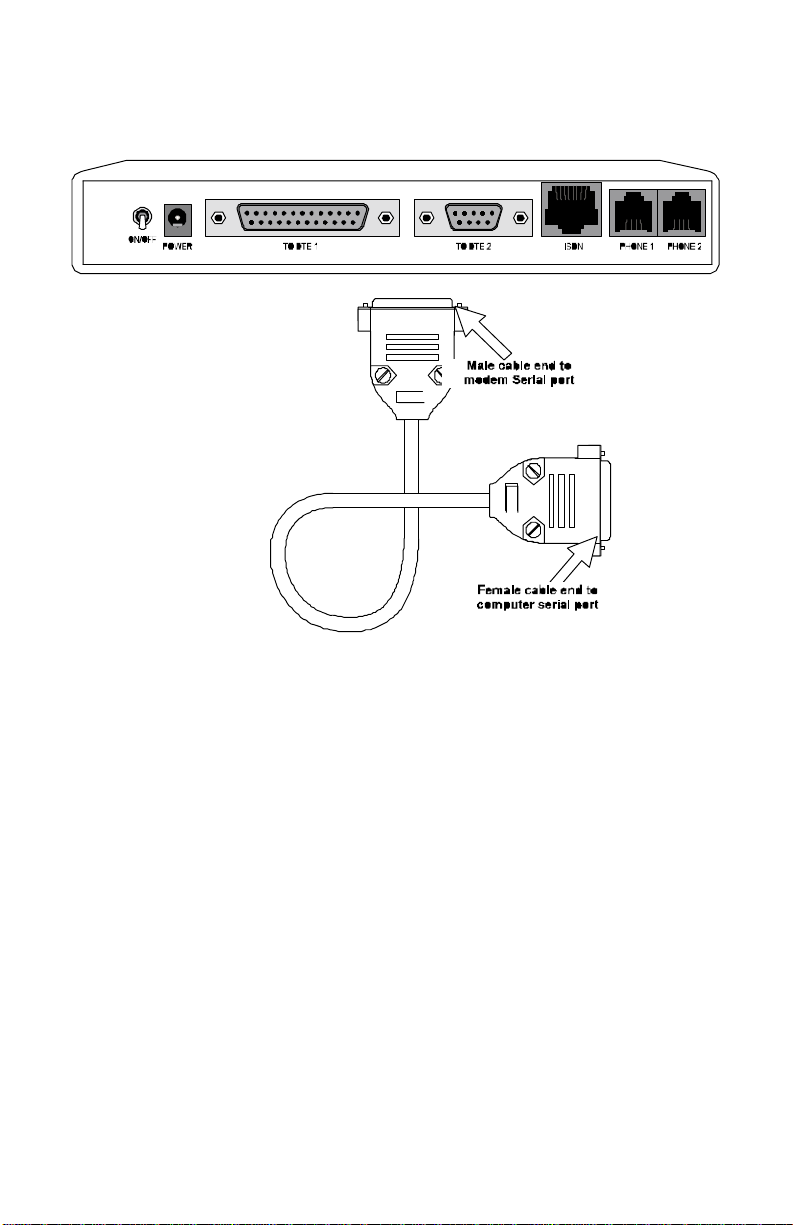
Connecting the TA128 to your Computer Serial Port
Figure 2 -2 Connecting the TA128 to Your Computer
Complete the following steps to connect the TA128 to your
computer:
1. Turn off the power to your computer.
2. Connect the male end of the 25 pin cable to serial port1.
3. Connect the other end of the cable (female end) to your
computer’s serial port. In case your computer only supplies a 9
pin serial connector, you will need to use a 25 pin to 9 pin
converter (9 pin female to 25 pin male). If you have another
type of serial port connector, such as on the Macintosh, you
will need a special cable for the connection.
4. Once the connection is made, turn the computer back on.
7
Page 20

Connecting the TA128 to Your ISDN Line
The TA128 comes with a choice of two types of ISDN line
interfaces:
• S/T interface - This can only connect to your NT-1 (Network
Termination) device.
Warning:Do not under any circumstances connect directly to the ISDN
wall jack.
• U interface - This allows you to connect directly to your ISDN
wall jack.
Warning:The ISDN jack is for ISDN line connection only. Connection of a
phone line may result in damage to your Terminal Adapter.
Attention: La fiche ISDN est destinée uniquement pour la connexion
sur une ligne RNIS. La connexion sur une ligne téléphonique
peut endommager votre adaptateur de terminal.
U Interface Model
If you have purchased the TA128 U-interface model, you can
connect the U-Interface directly to the wall jack.
In most cases, the ISDN jack installed by the phone company is a
RJ-11 jack (except in Canada, where RJ-45 jack will be installed),
and the U-Interface jack on the back of the TA128 is a RJ-45 jack.
A RJ-45 to RJ-45 (or RJ-11 to RJ-45, depends on your regional
distributor’s request) phone cable is included with your TA128.
To connect the TA128 to your ISDN line:
• Connect the RJ-45 connector to the “ISDN U” jack on the
back of the TA128.
• Connect the other end of the RJ-45 cable (or RJ-11) to your
wall jack.
8
Page 21
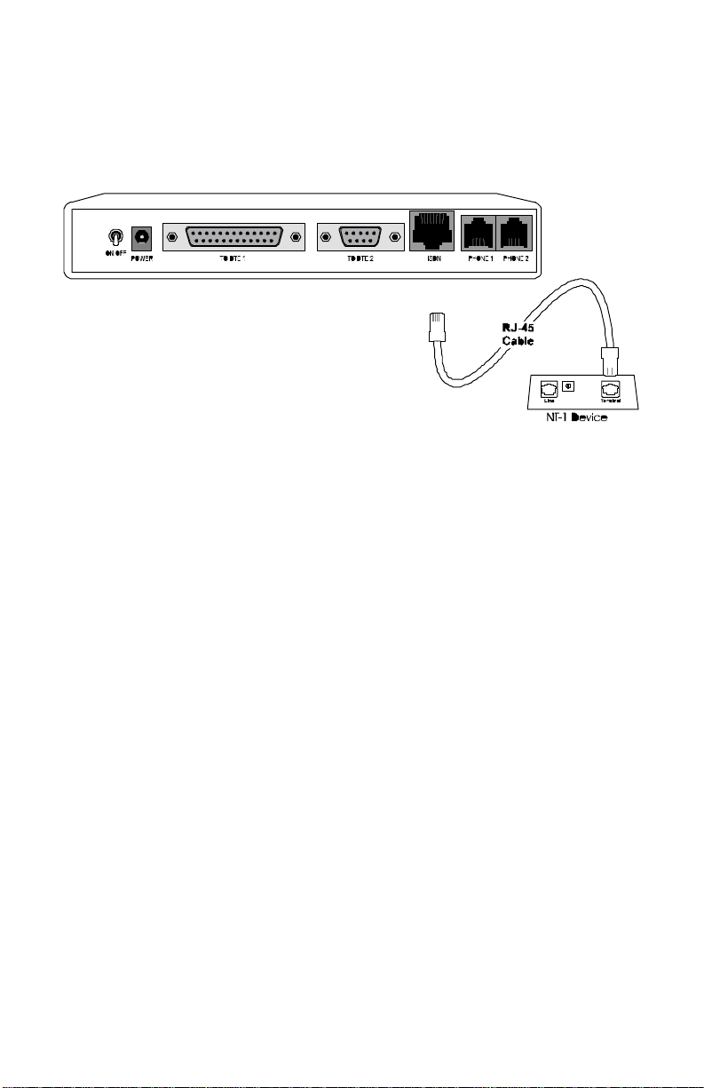
S/T Interface
If you have purchased the TA128 S/T model, you will need an NT1 device to connect to the network.
Figure 2 -3 Hooking Up an NT-1 Device
Power On and Self Diagnostics
Once you have completed all of the installation steps above, flip the
TA128’s On/Off switch to the ON (up) position.
The unit should cycle through a self test sequence, where you
should see a series of LED lights blinking (LED, B1, B2, AA). After
this cycle is complete, the PWR light should stay on.
If the test routine fails, the LNK LED flashes. Refer to Chapter 15 ,
for more information on self-tests and error codes.
If you have a communication program loaded and active
(connected to the same serial port as the TA128), you should see
the DTR LED should be ON after the self test.
9
Page 22
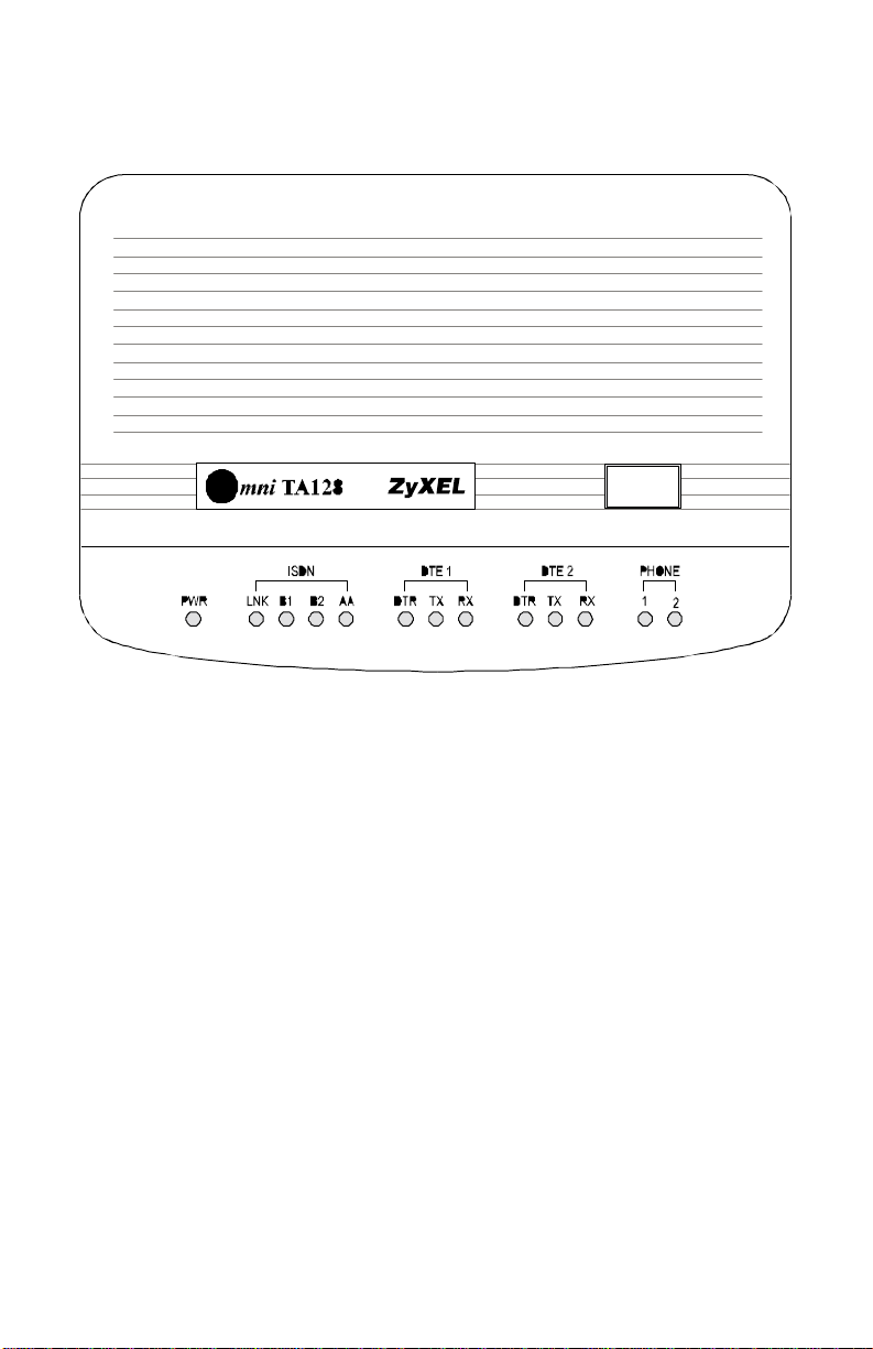
TA128 Front Panel
Figure 2 -4 TA128 Front Panel
The LED Indicators
PWR - The power on LED lights up when the TA128's power is
turned ON.
LNK - The Link LED lights up when the link with the local switch
is active and flashes when attempting to make a connection.
B1 - The B1 channel connection LED lights up when the B1
channel is established.
B2 - The B2 channel connection LED lights up when the B2
channel is established.
AA - The auto-answer LED lights up when the TA128 is in Auto
Answer mode and flashes when it rings.
10
Page 23

DTR - The data terminal ready LED lights up when the DTE or
computer connected to the DTE Port indicates that it is ready for
communication by raising the corresponding RS-232 signal.
TX - The transmit data LED flashes when the DTE/Computer is
transmitting data to the DTE Port of the TA128.
RX - The receive data LED; lights up when the DTE/Computer is
receiving data from the DTE Port of the TA128.
Phone 1 - The phone 1 LED lights up when the POTS port 1
telephone/handset is off-hook.
Phone 2 - The phone 2 LED lights up when the POTS port 2
telephone/handset is off-hook.
Front Panel Switch
When the TA128 is in command state, pressing the front panel
button causes it to dial the default phone number pre-stored in the
NVRAM. The default number pointer to the telephone directory is
assigned by the AT*Dn command.
When the TA128 is on-line, pressing the button will tear down the
connection and bring it into command state.
To restore the TA128 to its factory default settings and initiate the
loop-back test, turn the power ON while pressing and holding the
switch. Continue holding the switch for 3 to 5 seconds after turning
the power ON.
11
Page 24

12
Page 25

3 Configuring Your ISDN
Line and Network
The set up procedure for the TA128 needs to be done only once.
The settings will be stored in non-volatile RAM. The only time you
will need to reconfigure your line is when you perform a hardware
reset on your TA or when you change options on your ISDN line.
There is a simple Windows 3.x, NT4.0 or 95 utility provided by
ZyXEL to help you set-up the TA128. We will explain how to
setup your switch using a Windows/Windows 95 utility which
comes with the TA128.
If your TA128 is not going to be set up by a computer running
Windows, you will need some type of terminal program that allows
you to send AT commands to the TA and receive responses from
the TA.
Configuring Your TA using a Configuration
Utility
Along with your TA128, you will find a disk labeled “ZyXEL
ISDN Configuration Manager”. Complete the following steps to
install this software:
1. Insert your ZyXEL Configuration Utility disk into the floppy
drive on your computer
2. From Windows 3.x choose Run... from the File menu.
3. From Windows NT4.0 choose Run... from the File menu.
4. From Windows 95 choose Run... from the Start menu.
5. Type: A:\setup.exe and press Enter.
6. Follow the instructions on your screen.
13
Page 26

Configuring your TA using a Terminal
program
If you are not using the ISDN configuration utility that is packaged
with the TA128, you will need a terminal program with which to
configure the unit. The TA128 should work with any asynchronous
terminal program that can communicate directly with one of the
communication ports on your system. If you do not know how to
use a terminal program, refer to the instructions that came with the
terminal program.
Make sure the program is set up to communicate with the COM
port that the TA128 is connected to. You can check to see if the
DTR LED is on when the terminal program is active. In most cases,
if the terminal program is active and ready to communicate with
the port that the TA128 is connected to, it will activate the DTR
signal. This will cause the DTR LED to light up. If the DTR LED is
not ON, you will need to check the program’s settings.
The communication speed can be set to anywhere between
2,400bps and 460,800bps, but 115,200bps is a good default value.
The TA128 will automatically adjust its speed to match your
communication speed.
Once the terminal communication program is ready, you can type a
simple command to see if the TA128 responds.
Type:
AT<Enter>
TA128 should respond:
OK
Type:
ATI<Enter>
TA128 should respond:
1281
14
Page 27

Type:
ATI1<Enter>
TA128 should respond:
TA128 USA: V 1.00a (Firmware version number)
7607 (Firmware checksum will change based on your firmware version)
OK
Once the TA128 accepts the commands that you typed, it is ready
to be programmed and ready to operate with your ISDN network.
If you do not receive any response from the device, go over your
installation procedures again or contact ZyXEL Technical Support.
15
Page 28

16
Page 29

4 ISDN Communication
Basics
In this chapter, we will cover how to initiate and receive calls over
digital lines using your TA128.
Understanding AT Commands
AT commands are used to configure and control the TA128.
Command statements are usually sent to the TA by being typed
from the computer keyboard.
Command statements must be written in a specific form in order
for the TA128 to recognize them. A command statement begins
with the letters “AT” or “at”. It is then followed by one or more
commands and then by <Enter>.
AT commands can only be issued when the TA128 is in
“command” or “off-line” mode.
Once the TA128 has established a connection with the remote
device, it goes into “on-line” mode, and the characters sent from
your computer (through the TA128) are transmitted to the remote
device.
In order to issue an AT command statement, you first need to run
your communications software and configure it to the port
connected to the TA128. Refer to your communications software
manual if this is not the case.
Once the communication terminal program is running and the
TA128 is connected:
Type:
AT<Enter>
17
Page 30

TA128 responds:
OK
This confirms that the TA and your computer are communicating
correctly.
Supported AT command types:
Type of AT Command Example
Basic AT (Hayes compatible). ATA
Basic AT$ (on line help). AT$
Extended AT&. AT&F
Extended AT* command. AT*I1
S-Register command. ATS0=1
S-Register bit-mapped command (set S-
Register bit 1 equal to 1).
ATS13.1=1
S-Register inquiry command. ATS0? Or ATS13.1?
You may also browse the list by using AT$.
Quick Tips when issuing AT commands:
The ENTER or RETURN key must be pressed to execute a
command.
Multiple AT commands can be combined into one line. For
example, AT&O2 and ATB02 can be combined into one line
AT&O2B02.
The TA128 processes commands from left to right. The AT
command that appears to the right might over-write the command
to the left. For example, ATB13B14 will result in ATB14 since both
B13 and B14 can not co-exist.
If you see duplicated characters for each one you type, your TA128
and software both have their echo feature turned on (the TA128
defaults to enable command echo). To eliminate the double
characters, turn off software command echo.
18
Page 31

Use “A/” to repeat the last command. No ‘AT’ prefix is needed for
this command.
The TA128 supports either verbose result code (i.e. “OK”) or
numerical result code (i.e. “0"). You can use ATVn command to
set it one way or the other:
Command Description
ATV0 Select numerical result code.
ATV1 Select verbose result code.
Outgoing Calls
The TA128 has 3 modes in which to send communication over
ISDN network.
• ISDN data.
• Analog port, Phone 1 communication.
• Analog port, Phone 2 communication.
These modes are auto-switching based on the commands you
issue. Let’s take a look at how the communication mode is
automatically switched. At your terminal program, proceed with
the following instructions:
Dialing out using ISDN mode
The command “ATDI” tells your TA128 that you want to make an
ISDN data call and to therefore use the ISDN mode to call out.
Type:
ATDI17142630398<enter> (Make an ISDN call)
Dialing out using ISDN mode’s optional Speech Bearer
Service
TA128 supports ISDN data utilizing Speech Bearer Service. To
enable this function, you need to set S-register S83 bit 7 to 1
19
Page 32

(ATS83.7=1). This function is useful in the areas where ISDN
service providers charge lower usage rate for voice (speech) calls.
To enable this function, type:
ATS83.7=1<enter>
To disable it, type:
ATS83.7=0 <enter>
Dialing out for Analog Adapter Port 1
Using the “A” command following the “ATD” will tell your
TA128 to automatically switch call to analog adapter, Phone 1,
once dialing is complete.
Type:
ATDA17146930762<enter>
OO NOTE: You must have an analog modem connected to your analog port
before you issue this command.
Dialing out for Analog Adapter Port 2
Using the “B” command following the “ATD” will tell your TA128
to automatically switch calls to analog adapter Phone 2, once
dialing is complete.
Type:
ATDB17146930762<enter>
Manually switching communication modes
The manual switching functions will only be necessary if your
communication software does not allow you to change your dialup string.
Conventional dialing commands: ATD, ATDT and ATDP, used by
many existing communication software, can be mapped onto one
of the new dialing commands according to the AT&O setting as
follows:
20
Page 33

AT Command Dial string it will map to
AT&O0 ATD, ATDT and ATDP are the same as ATDB.
AT&O2 ATD, ATDT and ATDP are the same as ATDI.
AT&O3 ATD, ATDT and ATDP are the same as ATDA.
The factory default is AT&O2. This means the TA will select ISDN
data mode when you do not specify which communication mode
to use (i.e. ATD or ATDT).
Placing the Call
To initiate a call, choose the proper communication mode and
configure the mode according to the bearer service (or protocol)
you want to use. Here are some simple commands that will be
useful when placing a call:
Command Description
ATBnn Changes ISDN B channel protocol setting.
ATDL Re-dials the last dialed telephone number.
Incoming Calls
When a call comes in, it will be carried by one of the following
protocols:
• V.120
• HDLC PPP, MPPP or SLIP
• V.110
• X.75
or the call may be initiated by an analog device.
This section will provide some general guidelines for setting up the
device for call answer handling. Be aware that the TA128 will not
automatically answer a call unless S-register S0 is set to a value
greater than 0 (zero). If S-register S0=0, the TA128 will only report
21
Page 34

audible tone that will allow you to decide whether or not you
should take any action.
When an ISDN data call comes in, the TA128 will try to negotiate a
connection using the proper ISDN protocol. When an analog call
comes in, the TA128 will send the call to the analog port as the
factory default, Phone 1 and then Phone 2.
Digital Data
The TA128 currently supports Circuit Switched Data (CSD) for
ISDN data applications. The CSD protocols supported by the
TA128 include: PPP, MPPP, V.120, X.75, and V.110. PPP is the
most popular protocol used in North America; it is used by most
Internet service providers. Once the TA128 answers a call, it will
examine the incoming data to determine which protocol to use, and
automatically switch to this mode. The TA128 is able to autoswitch for PPP, MPPP, V.120, X.75, V.110, and above protocols
over the speech channel. In most cases, you can rely on the autoswitching feature for your applications. If you need more specific
settings for answering calls, refer to the section entitled “Answering
a Call using MSN” found later in this chapter.
OO NOTE: For DTE Port 2, only PPP, V.120, and X.75 are supported.
Determining the Packet Length
The user’s information is sent on a frame-by-frame basis for V.120
and X.75. Sometimes we call it “packetized.” The maximum frame
length on the sending side should not exceed the maximum frame
length that the receiving side allows. Sometimes this information
will be exchanged during handshaking. However, few
manufacturers, if any, have implemented this mechanism.
If the sending side sends packets greater than what the receiving
side allows, the receiving side will discard the frame and reply with
a Frame Reject frame (FRMR). FRMR indicates that the
22
Page 35

information received is too long. Both sides will then reset their link
layer negotiation and re-send the frame again. Usually this will
happen repeatedly until the call gets disconnected.
The TA128 has a fixed maximum receiving frame size of 2048
octets which is larger than most devices can support. The default
maximum sending frame size is 252 octets for V.120 and 2048 for
X.75. If you need to change the maximum sending frame size, the
ATCL command should be used.
Type:
ATCL252<Enter> (Set the frame size to 252 octets,
user value between 1-2048)
TA128 responds:
OK
Type:
ATCL?<Enter> (To inquire about the current
setting of the packet length)
TA128 responds:
Maximum user data length in a packet (byte) : 252
Answering a Call using MSN
When answering an incoming call, the call will first be identified if
the caller number matches the MSN settings.
The Multiple Subscriber Number (MSN) supplementary service
enables multiple ISDN numbers to be assigned to a single ISDN
BRI line. It allows the caller to select, via the public network, one or
more distinct terminals from a variety of terminal choices. Since the
Omni supports many different communication protocols and two
analog adapters, each of these ports can be assigned to an ISDN
number using the following command:
AT&ZIn=s (where ‘s’ is the MSN)
&ZI0=s assigns MSN ’s’, phone number for X.75.
23
Page 36

)
&ZI1=s assigns MSN ’s’, phone number for V.110.
&ZI2=s assigns MSN ’s’, phone number for V.120.
&ZI3=s assigns MSN ’s’, phone number for PPP, MPPP.
&ZI4=s assigns MSN ’s’ for ISDN data, protocol auto-
detection.
&ZI5=s assigns MSN ’s’, phone number for DTE Port 2.
&ZI6=s assigns MSN ’s’, phone number for Phone 2.
&ZI7=s assigns MSN ’s’, phone number for Phone 1.
AT&ZI? can be used to display the MSN numbers. The factory
default for these numbers are UNASSIGNED.
If an incoming SETUP message is offered with addressing
information (i.e. the appropriate part of the called_party_number),
this address will be compared with the MSN numbers assigned by
the AT&ZIn=s commands. The call will be accepted using the
specific protocol, if the assigned number of this protocol matches
the received called party number.
OO NOTE: You are not required to enter the complete number string for the
AT&ZIn command. The last few distinguishable digits will be
enough for the TA128 to make the decision. Two phone number
strings are said to be matched if their least significant “n” digit(s)
are identical, where “n” is the number of digits in the shorter
string.
Called_Party_Subaddress information within the incoming SETUP
message can also be used to select the protocols and/or analog
ports. In normal conditions Called_Party_Subaddress information
is not used by the TA128 to select the protocols or services, but
only indicates the subaddress (if any) to the DTE. Refer to Chapter
11 for more detailed information.
Data over Speech Channel
If you are expecting ISDN data calls through the Speech (Voice)
channel, you need to setup MSN for it. If no MSN entries are
24
Page 37

found in MSN ISDN data lists, all Speech (Voice) calls will be sent
to either Phone 1 or Phone 2. Which entry to use would depend on
the type of data call that you are expecting. If you only expect PPP
calls, you should enter the number that the remote user will use to
dial in entry #3 (AT&ZI3=xxx) or entry #5 (A&ZI5=xxx). Once
this is set, the TA128 will attempt to use PPP protocol to
handshake with the remote site whenever a caller dials into this
number.
Best-effort call answering
If some numbers have been set using the &ZIn command (this can
be seen by issuing the AT&ZI? command) and they are not
matched with the address of the incoming call, the TA128 will, by
default, ignore the call as it may be intended for other devices that
share the same S/T interface (S0 bus) with the TA128.
If you want the TA128 to answer inbound calls using all possible
protocols, you can set the best-effort call answering bit as follows:
Command Function
ATS119.3=0 Answer call only when number matched. (default)
ATS119.3=1 Best effort call answering.
Ambiguity resolution switch for voice calls
For a Speech or voice-band-data call, if the &ZI number
assignment can tell which of the analog adapters is being
addressed, then the call will be delivered to the proper destination.
But sometimes, ambiguity of address matching may exist. This
may happen if the &ZIn numbers of the various protocols are
either unassigned or not matched. In this case, users may wish to
set answering priority to an analog port. The AT&Ln command
sets the address ambiguity resolution flag as follows:
AT&L0 - Analog adapter 1 has the higher priority to answer a
voice or voice-band-analog-data call; if analog adapter 1 is busy,
the call will be routed to analog adapter 2.
25
Page 38

AT&L1 - Analog adapter 2 has the higher priority to answer a
voice or voice-band-analog-data call; if analog adapter 2 is busy,
the call will be routed to analog adapter 1.
Multi auto-answering of data calls
When an ISDN data call comes in, the TA128 can determine the
protocol to be used in one of two ways:
1. By way of the information conveyed by the SETUP message
(for DSS1, these include the Bearer-Capability, Low-LayerCompatibility, or High-Layer-Compatibility information
elements; for 1TR6, these include the Service Indicator as well
as an Additional Octet of the Service Indicator)
2. By the Multi Auto-answering process. The TA128 determines
the protocol by monitoring the B channel signal sent by the
calling site.
With either method, the data call can be identified by the TA128 to
be X.75, V.110, V.120, or PPP, MPPP Async-to-Sync conversion.
If the address-matching process is again unable to tell which
protocol to use, the TA128 will go into its “Multi Auto-answering
Routine,” by examining the B channel data pattern and hence
determine the protocol to use.
When alerted, the TA128 will send a RING message to the DTE in
the following format:
RING
FM:17145522863 TO:17142630398
26
Page 39

5 Setup for Windows 95
and NT 4.0
This chapter contains step by step procedures for installing the
Windows 95 and NT drivers, and configuring Dial-up Networking
for the TA128.
Installing the Windows 95 Driver (INF file)
If your computer supports Plug & Play be sure your TA128 is
powered on before starting your computer. If you are using a non
PnP protocol follow the steps below to complete installation:
1. Open the Control Panel by double clicking the “Control Panel”
icon in your “My Computer” folder.
2. Double click “Modems,” then click the “Add” button. The
following dialog box will appear.
3. Select “Don't detect my modem; I will select from a list.” Then
27
Page 40

4. Click the “Have Disk” button.
5. Insert the ZyXEL Windows 95 driver disk into your floppy
drive and click OK. If you have downloaded an updated INF
file from ZyXEL’s FTP, website, or BBS, use Browse to find
the location of the updated .INF file, click Open, then click
OK.
28
Page 41

6. Select the TA128 driver with the protocol that your host is
using. Generally, the samples listed below will work. However,
we recommend that you check with your ISP to verify the
protocol they use.
If you are connecting to an Internet Service Provider (ISP),
select:
• ZyXEL TA128, PPP 64K
If the ISP has not upgraded to an ASEND compatible server,
select:
• ZyXEL TA128 V.120 64K
If you are calling another location such as a BBS system, select:
• ZyXEL TA128 V.120 64K
If you dial up to CompuServe, select:
• ZyXEL TA128 V.120 64K
If you are calling MicroSoft Network's (MSN) ISDN line, select:
• ZyXEL TA128, PPP 64K
After you have completed the selections above, click Next.
29
Page 42

1. Select the COM port your TA is connected to and click Next. A
final dialog will appear. Click Finish. You should see a window
similar to the one below:
2. Click Close. This completes the installation of your TA128
modem driver. You may now use programs such as “Dial-Up
Networking” with your TA128.
30
Page 43

Configuring Windows 95 Dial-Up
Networking
This section assumes you have already fully installed Windows 95.
If you have not installed the Dial-Up Networking feature in
Windows 95, please install it before you continue.
1. Double click on the “My Computer” icon and then double
click on the “Dial-up Networking” icon. From within the Dialup Networking folder, double click on the “Make New
Connection” icon.
2. Choose a name for your connection and select your modem
type from the drop down window. Then click on the “Next”
button.
31
Page 44

3. Type the phone number of your ISP or of host you will be
calling. Click on the “Next” button.
4. Click on the Finish button. A new icon is created in the Dial-up
Networking folder.
5. Right click on this icon, then select “Properties” from the
menu.
6. Make sure your TA128 appears in the “Connect Using” box.
Then click on the “Server Type” button.
32
Page 45

• These options are mostly host or server specific.
• If you are using PPP, use the default settings shown above.
• If you are connecting to a LAN, then select “Login to
• If you are logging on to a Microsoft Windows network,
select “NetBEUI.”
• If you are logging on to a Novell network, then select
“IPX/SPX Compatible.”
• If you are logging on to an Internet connection, then select
“TCP/IP.”
7. Click on “TCP/IP Settings.”
33
Page 46

If your host requires you to specify an IP address (Static IP),
then click on the "Specify an IP address" radio button and enter
your IP address. Otherwise, leave the "Server assigned IP
address" checked. Most servers assign an IP to you when you
log in.
Click the “Specify name server address” radio button and enter
your primary and secondary DNS (Domain Name Server) IP.
Obtain the DNS numbers from your ISP. In most cases, you
should leave "Use IP header compression" and "Use default
gateway on remote network" checked. When all of the
selections have been made, click “OK.”
8. This completes the remote connection definition. Locate the
new connection icon in your “Dial-up Networking” folder, and
double click on it.
34
Page 47

9. If the User name and Password are incorrect or are not there,
type them in. Click on the Connect button and your TA128
will dial the number and establish a connection.
CAPI Installation
Follow the steps below to install the ZyXEL Internet Configuration
Manager and ZyXEL CAPI drivers:
1. From the Win95 Start button choose Run.
2. From the Run dialogue box type: A:\Setup.exe and click OK.
3. From the ZyXEL ISDN Installation dialog box choose the
appropriate CAPI driver and click the Install button.
35
Page 48

4. From the Question dialogue box click No if you do not wish to
setup Multiple Subscriber Numbers. This completes CAPI
installation. If you click Yes continue with the steps below:
Only CAPI 1.1a requires setup of Multiple Subscriber
Numbers.
5. From the Set Multiple Subscriber Numbers dialog box type in
the desired numbers and click OK.
36
Page 49

6 Point-to-Point Protocol
(PPP)
Introduction
Point-To-Point Protocol is designed for simple links which
transport packets between two peers. These links provide fullduplex simultaneous bi-directional operation, and are assumed to
deliver packets in order. PPP is intended to provide a common
solution for easy connection for a wide variety of hosts, bridges
and routes.
In the process of configuring, maintaining and terminating the
point-to-point link, PPP goes through several distinct phases which
are specified in the following simplified state diagram:
37
Page 50

Up Opened
Dead Establish Authetication
Fail
Down
Fail
Closing
NetworkTerminate
Figure 6 -1 Point to Point Link Pathway
Data will be transmitted only when the link is in the open phase.
Negotiation details are described in RFC1661.
Feature list
Async to Sync Conversion
PPP uses HDLC-like framing as encapsulation, which can be bitoriented or character-oriented. Most ISDN routers use bit-oriented
HDLC framing, also known as synchronous transmission.
However, serial transmission in most personal computers is still
character-oriented, also known as asynchronous transmission. In
order for an ISDN router and PC to communicate, it’s necessary to
do asynchronous to synchronous conversion. ZyXEL’s TA128 can
be used as a bridge. Any data from a PC to ZyXEL TA will be
converted from asynchronous to synchronous form and vice versa.
38
Page 51

PPP HDLC framing is described in RFC1662. PPP over ISDN is
described in RFC1618.
Related command:
• ATB40 - Async to Sync PPP conversion.
Authentication conversion
After a link is established, it is necessary to authenticate the peer
for security reasons. There are two popular authentication methods.
One is Password Authentication Protocol (PAP) and the other is
Challenge Handshake Authentication Protocol (CHAP). PAP is
less secure because it transmits the username/password in plain
text form. Unlike PAP, CHAP transmits the username/password in
coded form. Some ISPs may support CHAP as the only method
for authentication. For those applications which do not support
CHAP, the TA128 converts PAP into CHAP. By default, the
PAP/CHAP conversion is always activated, so the authentication
from the TA128 to PC is always PAP. That means you must
configure your software to accept plain text as password
authentication. Do not worry about password leakage, the TA128
will send the password out in hashed form by CHAP. Sometimes
CHAP can not be supported by the ISP. You may set S87.2=1 to
use PAP only. If you do not want to do authentication at all, set
S118.3=1 to disable the conversion.
OO NOTE: Disabling authentication may cause problems in Windows 95.
CHAP is described in RFC1994 and PAP is described in RFC1334.
The only hash method supported by CHAP is MD5, MS-CHAP
isn’t supported yet. At this time authentication conversion works
for clients only.
Related commands:
• ATS118.3 = 1 - Disable authentication conversion.
• ATS118.3 = 0 - Enable authentication conversion depends on
S87.2 (default).
39
Page 52

• ATS87.2 = 1 - Accept PAP/None only.
• ATS87.2 = 0 - Accept CHAP/PAP/None (default).
Compression Control Protocol (CCP)
The ISDN channel can be utilized more effectively when using
compression. Compression Control Protocol (CCP) is used by PPP
to negotiate compression methods between peers. CCP starts after
the PPP reaches the network phase. Both ends must support the
same compression method to start packet compression. ZyXEL
supports STAC/LZS. Right now STAC/LZS is only supported with
single history check mode 0 (none), 3 (sequence) and 4 (extended).
Mode 1 (LCB) and mode 2 (CRC) are not supported due to patent
limitations. CCP negotiation is described in RFC1962. STAC/LZS
is described in RFC1974. The TA will monitor the DTE’s activity.
If software compression has been negotiated, the TA will
automatically disable STAC/LZS compression.
Related commands:
• AT&K00 - Disable CCP negotiation (default).
• AT&K44 - Enable CCP negotiation.
Multilink PPP
There are two B channels in basic rate ISDN. This offers the
possibility of opening multiple simultaneous channels between
systems giving users additional bandwidth on demand. Multilink
PPP is a method for bundling both B channel into one PPP link for
higher throughput. It must be negotiated in the link establish phase
by both peers. If Multilink PPP is negotiated successfully, the
second link will be dialed after the first link reach network phase. In
some countries the directory number is not the same for both
channels. For dialing the second B channel with a different
directory number, both numbers must be obtained before dialing
out unless the peer supports BACP/BAP, which will be described
later in this chapter. Multilink PPP is described in RFC1990.
40
Page 53

Related commands:
• AT&J3 - Enable Multilink PPP.
• ATDI<num1>[+<num2>] - Dial Multilink PPP with num1
twice or with num1 and num2 if they differ.
• ATS61.3 = 0 - Use rotate method to bundle both channels
(default).
• ATS61.3 = 1 - Use split method to bundle both channels.
• ATEPDn = <num> - Set End Point Discriminator(EPD) for
class n (0-5). I is not required to change the default settings in
most cases unless your ISP provides these values.
Call bumping
You can place or answer a voice call from a device that is attached
to one of the POTS ports while Multilink PPP is active. The TA128
drops one of the channels automatically and uses it for voice calls.
Once a voice call ends, TA128 automatically reestablishes the
channel. For fully disconnecting with the central switch, there is a
delay time between on-hook phone and channel reestablishment.
The delay for reestablishing the channel is 10 seconds. During call
bumping, the traffic for BOD is still under calculation. In other
words, the add persist time is calculated from the time when the
traffic is above the add threshold whether or not the phone is onhook or off-hook. However, it won’t dial until the phone has been
on-hook for 10 seconds.
Call bumping works for both client (dialing) side and server
(answering) side. However, the channel reestablishment is only
effective on the client side.
Related commands:
ATCE0 - Disable the call bumping function.
ATCE1 - Enable the call bumping function (default).
41
Page 54

Bandwidth On Demand (BOD)
The function of bandwidth on demand (BOD) will monitor the
traffic on ISDN links while Multilink PPP. If there is light traffic on
the link, one of the channels will be dropped automatically. On the
other hand, if only one B channel is used and data traffic is high
enough, BOD will establish the second B channel to increase the
bandwidth of the data link. The wait for the second B channel’s
carrier is 60 seconds. If the second B channel can’t be connected
successfully the BOD will try again after 60 seconds. If the second
call is connected but negotiation failed, it will be retry three times.
If a connection is not established after the third try the Multilink
PPP will be disabled automatically.
For BOD, there are four parameters to set high/low threshold and
persist time. Traffic utilization is measured in the ISDN link. Highly
compressible data may not generate enough traffic to start the
second B channel. Both add persist time and subtract persist time
must be set to activate BOD.
Related commands:
• ATJAn - Add traffic threshold for n K bits per second, n = 48
(default).
• ATJSn - Subtract traffic threshold for n K bits per second, n =
32 (default).
• ATKAmn - Add persist time for n period in m unit, n = 0 - 127,
m = s for seconds and m for minutes.
• ATKSmn - Subtract persist time for n period in m unit, n = 0 -
127, m = s for seconds and m for minutes.
BACP/BAP
Bandwidth Allocation Control Protocol and Bandwidth Allocation
Protocol is used for call request and link drop under Multilink PPP.
BACP is negotiated during the network phase. Without
BACP/BAP, the directory numbers of both B channels must be
42
Page 55

specified before dialing out. In some cases, it is not possible for the
ISP to support more than one chassis that is capable of bundling
both channels at the same time. With BACP/BAP, the second B
channel’s directory number can be obtained while requesting a call.
The second directory number is not necessary any more. The
BACP/BAP is supported on the client side only. The server side of
BACP/BAP will be implemented in an upcoming release.
Related commands:
ATBP0 - Disable BACP/BAP negotiation.
ATBP1 - Enable BACP/BAP negotiation (default).
OO NOTE: The status of BACP/BAP negotiation can’t be saved in profile.
It’s enabled after power on. The status can be changed only by
the power cycle of another ATBP command. AT&F and ATZ
doesn’t change the status.
43
Page 56

44
Page 57

7 V.110 and Synchronous
Mode Communications
V.110 is most popular in Japan. The table below shows the
specifications of different ISDN protocols:
Synchronous V.110 X.75/V.120
Layer 1 Transparent 80 Bits
Framing
Layer 2 None None LAPB/LAPD
Layer 3 None None ISO8208 T.70
Error Control No No Yes
V.42bis No No Yes
Async or Sync Sync Async Async
Bundle Yes (Note) No Yes
Max. Line
Speed
AT-Command
Configuration
Note : BONDING protocol for synchronous mode will be F/W upgradeable at
ZyXEL‘s option.
64Kbps
128Kbps (Note)
ATB11&M1
(Sync Data)
ATB11&M3*I1
(V.25bis Sync HDLC)
38.4 Kbps 64Kbps
ATB10 ATB0:
HDLC
NL/ V.120
128Kbps
Transparent
ATB01: T.70
NL/ ATB20
Answering a V.110 call
Once you set the proper V.110 communication mode, either
asynchronous or synchronous, there is no need to configure the
ISDN mode to the protocol of an incoming call. The TA128 will be
able to determine the correct protocol to use by examining the data
coming in from the remote site if the device is set to auto-answer or
once an answer command is issued.
To allow the TA128 to answer the incoming call, you need to set
S0 to a value greater than 0 (i.e. ATS0=1). If S0 is not set (S0=0),
45
Page 58

the DCE will report “RING” and will also make an audible ring
notification.
Making V.110 Calls
Before the ATDIxxx command is given to place the call, you need
to make sure that the TA128 is in asynchronous mode (AT&M0).
Then use the following commands to configure V.110:
AT Command Description
ATB10 User rate follows DTE speed (see note below).
ATB13 User rate = 2400bps.
ATB14 User rate = 4800bps.
ATB15 User rate = 9600bps.
ATB16 User rate = 14400bps.
ATB17 User rate = 19200bps.
ATB18 User rate = 38400bps.
ATB19 User rate = 57600bps (Japanese version only).
The highest Async V.110 user rate depends on bit 4 of S119 as
follows:
S119.4=0 19200 bps.
S119.4=1 38400 bps for areas other than Japan (default).
S119.4=1 57600 bps for Japanese version.
If the DTE speed is higher than what has been set, the user rate on
above table will be used.
Synchronous Connections
Use the following commands to choose the data rate for
synchronous operation :
ATB11 64000bps
46
Page 59

ATB19 56000bps
There are two modes of synchronous operation:
1. Asynchronous commands, synchronous data (AT&M1):
The TA128 accepts AT commands in asynchronous mode.
Once the call is connected, it enters synchronous mode for data
transmission.
2. Synchronous mode (AT&M3*I1): The TA128 accepts
synchronous commands from V.25 bis or a PC with an add-on
synchronous card, and exchanges data synchronously with a
remote TA.
OO Note: The TA128 does not support network independent clock
compensation. The synchronous timing source must be supplied
by the TA128 , which is phase locked to the network
synchronous clock.
When in V.25bis command mode, the TA128 supports the bitoriented HDLC (High-Level Link Control) synchronous protocol
which most synchronous communication links use. Use AT*Ii to
enable V.25bis commands. For synchronous applications the TA is
set for use with one application, in normal situations. Save the
desired settings in the power-on profile and the TA will start up in
synchronous mode with V.25bis enabled. A special command set
RST is provided to get the TA back to asynchronous AT command
mode from V.25bis mode.
When the TA is used as a DCE device with a router or main-frame
system, use the following command string for best results:
AT&S1&M3*I1&W0Z0
V.25bis Command Set
Command Messages
CRN <dial string Dial command with number provided.
47
Page 60

Command Messages
CRSn Dial command with number from memory,
0<=n<=39; n is the memory location.
PRNn;<number> Saves <number> to address n (0<=n<=39).
CIC Receive incoming calls.
DIC Reject incoming calls.
RST Changes to asynchronous AT command
mode.
Indicator Messages
CNX Call connect.
INC Incoming call.
VAL Valid command.
INV Invalid command.
CFLxx Call Failure.
NT Answer tone is not detected.
AB Abort call.
ET Engaged tone.
NS Number is not stored.
RT Ring tone.
DTR Drop-Dialing Operation
The TA128 will automatically dial the phone number stored in the
NVRAM when it detects an off-to-on transition of the DTR line.
Before you enable the DTR drop action, a phone number must be
stored and saved to memory along with an indication of which
number to dial on DTR drop. First use AT&Zn=s (n=0-39, s=phone
number) to store the phone number into NVRAM. Then, use
AT*Dn (n=0-39) to choose which of the in-memory phone
numbers should be dialed. Finally issue an AT&D1 to enable DTR
drop dialing operation.
OO Note: Phone numbers must include a prefix for specific call types, e.g. I
for ISDN.
48
Page 61

An example of DTR drop dialing is given below. The destination
phone number is 5551234.
1. Issue the command
AT&Z0=I5551234
to save phone number to NVRAM.
2. Issue the command
AT*D0
To set phone number 0 as the DTR drop destination phone
number.
3. Issue the command
AT&D1
Enable DTR dialing operation.
4. Turn the TA off and back on.
49
Page 62

50
Page 63

8 V.120 ISDN
Communications
This chapter describes how to set-up and configure your TA128
with the V.120 ISDN protocol. The table below shows the
specifications of different ISDN protocols:
V.110 V.120 X.75
Layer 1
Layer 2
Layer 3
Error Control
V.42bis
Async or Sync
if used with VSeries DTE
Bundle
Max. Line
Speed
AT-Command
Configuration
80 Bits
Framing
None LAPD LAPB
None V.120 ISO8208T.70 NL
No Yes Yes
No Yes Yes
Async Only Async
No Yes Yes
Async: 38.4
Kbps
ATB10 ATB20 ATB00
HDLC HDLC
Transparent
Async Only
Only
64Kbps
128Kbps
64Kbps
128Kbps
Transparent
ATB01: T.70 NL
Placing outgoing calls
Some switches transmit all network signals through the D channel
(out of band signaling), allowing both B channels to be used
exclusively for your communication purposes. This allows for
throughput of 64Kbps per channel. However, not all switches
support out-of-band signaling at this time. For switches that do not
51
Page 64

support out-of-band signaling, network signals are transmitted
through the B channels. This reduces the bandwidth to 56Kbps.
When you are making a V.120 call, make sure that the
communication supports out-of-band signaling. If it does not
support out-of-band signaling, you will need to set your TA128 to
56K mode using the AT&E1 command (AT&E0 to set it back to
64k mode.) If your TA128 is on the receiving end, you can keep the
setting at AT&E0, 64k data mode. The TA128 will automatically
switch between the two speeds in answer mode.
Configuring the V.120 mode
To configure for a 56K V.120 call, type:
ATB20<Enter> (Select V.120 for communication)
TA128 responds:
OK
Type:
AT&E1<Enter> (Select 56K data mode)
TA128 responds:
OK
Now you are ready to dial the phone number. If you need to save
the setting into non-volatile RAM, issue the commands:
Type:
AT&W0<Enter> (Save the settings to profile 0) [Profiles available: 0-
3]
TA128 responds:
OK
Type:
ATZ0<Enter> (Save stored settings as the power on settings to profile
0) [Profiles available: 0-3]
TA128 responds:
52
Page 65

OK
All the above commands can be simplified by combining all of the
commands onto one line as follows:
AT&B20&E1&WZ0<Enter>
Dialing in V.120 mode
Finally, use the ATDn command to make the call (n is the phone
number you wish to dial). Once the connection is made, you
should see the following connect message.
CONNECT 115200/V120 56000/LAPD
This indicates that the connection is made with:
• DTE speed of 115,200bps.
• V.120 Protocol
• Data Speed of 56,000bps.
• Error Control LAPD.
Answering incoming calls
In most cases, there is no need to configure the TA128 to properly
answer calls. The TA128 is able to decide which protocol to use by
detecting the type of data that is coming in. All you need to do is
set S0 to greater than or equal to 1, so the TA128 will automatically
answer an incoming call. If S0=0, the DCE will simply report
“RING” to your terminal and sound a ring notification.
One exception to this is when the ISDN data call is carried through
Speech bearer. In this case, you would need to make an MSN entry
for the phone number that you are expecting the Data-overSpeech-bearer call. Use AT&ZI2=n. Refer to the section entitled
“Data over Speech Channel” in Chapter 0 for details.
53
Page 66

Speeds of 128Kbps
BRI ISDN consists of three (2B+D) logical channels. Each B
channel can be used independently for a dial-up connection
running at 56Kbps or 64Kbps (bits per second).
The two B channels can be used together for a single data
connection to provide 112K (with In-Band Signaling) or 128K
(when Out-of-Band Signaling is used). It is called a “Bundle
Connection”.
The type of channel bundling described in the V.120 section is
supported only between the following ZyXEL products: omni.net,
Omni TA128, or Elite 2864I, and uses Multiple Link Protocol
(MLP) and “cFos” channel bundling (CCB).
Identifying your line provisioning
For bundled connections, the two B channels of your ISDN line
must be able to handle data circuit switch connections with
unrestricted 64K or 56Kbps line speeds. Two separate data calls
will be established consecutively.
Making a Bundled Call with V.120
A bundled V.120 connection is initiated at the calling site when
ATB20 (B channel protocol V.120) has been selected and the
channel bundling mode has been enabled by an AT&J3
command. The channel bundling command (AT&J3) must be set
on both the calling and receiving sides, otherwise a single channel
connection will be made.
Type:
ATB20<Enter> (Set B channel protocol to V.120)
AT&J3<Enter> (Set the TA128 to make a bundled call)
Type:
AT&WZ<Enter> (If you want to save the setting)
54
Page 67

Once this is done, the ATD command will generate two
consecutive SETUP messages to invoke bundle initiation.
For the Northern Telecom switch, each BRI phone number can
only be called once at any given time. So if you dial this number, it
will report “busy” to any other incoming calls. In order to use two
B channels for aggregation, we must place two calls with different
phone numbers. To do this, separate the two numbers with a “+”
ATDI[phone_number_1]+[phone_number_2]<Enter>
The answering TA128 determines that the call is a bundle request:
when AT&J3 is set, and two consecutive SETUP messages are
received. The two data calls are established as one message. The
phone company’s ISDN line splits it off into two messages. That is,
the ISDN network treats them as two independent calls. Finally, the
receiving side receives one bundled message into the computer’s
serial port.
The success of a bundle connection initiation is indicated by the
connect message reported to the DTE:
CONNECT 115200/V120M 128K/LAPD
or
CONNECT 115200/V120M 128K/LAPD/V42b (with data
compression)
If you are not using American ISDN, you can have a choice
between Multiple Link Protocol (MLP) or “cFos” channel
bundling (CCB) two bundle protocols. You can set them by using
the following commands:
ATS100=0 MLP channel bundling
ATS100=1 CCB channel bundling
Dialing pre-stored phone numbers
Use ATDSn, n=0,1,..,39, to dial the (n+1)th phone number twice
for both the bundle connections. Use ATDSn+Sm, (n and
55
Page 68

n=0,1,...,39) to dial the (n+1)th phone number for the first
connection and the (m+1)th phone number for the second
connection.
For example, ATDIS0+S1<Enter> will dial the number stored in
location ‘0’, and the number stored in location ‘1’ for the bundle
connection.
Error Correction and Data Compression
with V.120
With V.120, the default setting is for LAPD error correction only.
No data compression will be negotiated. The following AT
commands are used to switch the V.42bis data compression on or
off for ISDN data calls when using V.120 protocol.
• AT&K44 - enables V.42bis on ISDN calls.
• AT&K00 - disables V.42bis on ISDN calls.
With the &K44 setting, the TA128 will try to connect using
V.42bis data compression. If the remote device doesn’t support
V.42, then LAPD error correction will be used.
When a connection is made using V.42bis compression, the
following connect message will be displayed.
CONNECT 115200/V120 56000/LAPD/V42b.
It takes extra time for the calling ISDN TA to negotiate V.42bis. If
you know in advance that the called site has no V.42bis capability,
it would be better to issue the AT&K00 command beforehand in
order to get a quick connection.
Since the V.42bis algorithm needs an error-free transmission
channel between the compression and decompression processes, it
can only work with a protocol with error control competence. X.75
and V.120 are such protocols that can be used together with
V.42bis data compression. V.110, on the other hand, is just an R-
56
Page 69

interface layer 1 adaptation protocol without error-control and is
thus inadequate for V.42bis.
Bundle Connection with V.42bis Data Compression
If both sites have set AT&K44 to enable V.42bis negotiation then
XID frames will be exchanged through the main B channel which
corresponds to the call established by the first SETUP message.
Only one data compression channel will be used in bundle
connections. That means the compression is done before packet
disassembly and the decompression is done after packet assembly.
The compression ratio of V.42bis is commonly recognized as up to
4:1 for text files. If the line speed is 128K bps, then the DTE speed
may reach 512K bps. This makes the DTE's normal RS-232 serial
port unsuitable for bundle applications. A special I/O card on the
computer side is required in this situation.
Selecting V.120 for European ISDN (DSS1)
With European ISDN, V.120 is an option in the Bearer Capability
(BC) information element, which is a mandatory information
element in the SETUP message. Although we can specify V.120 in
the Low-Layer-Compatibility (LLC) information element, some
switches just don't deliver the LLC. Other switches do deliver the
LLC, but the V.120 selection will be discarded midway.
If the called TA doesn't get any B channel protocol information
from the incoming SETUP message and the remote device is a
ZyXEL ISDN device, the TA128 will be able to identify the V.120
protocol automatically with the Multi Auto-answer routine.
Otherwise, the handshake will fail.
57
Page 70

Selecting V.120 for Germany National ISDN
(1TR6)
1TR6 data connections are achieved by setting the Service
Indicator to 7 (Daten_bertragung 64Kbps) and the Additional
Information octet is used to select B channel protocols. Since
there is no pre-defined code for asynchronous V.120, TA128 uses
the synchronous V.120 code to fill in the additional information
octet. This approach might not work all the time.
58
Page 71

9 X.75 ISDN
Communications
(Europe)
This chapter will describe how to set-up and configure your TA128
with X.75 protocol. The table below shows the specifications of
different ISDN protocols:
V.110 V.120 X.75
Layer 1
Layer 2
Layer 3
Error Control
V.42bis
Async or Sync
if used with VSeries DTE
Bundle
Max. Line
Speed
AT-Command
Configuration
X.75 was originally designed for packet-switched signaling systems
in public networks to provide data transmission services. But it is
now also used as the link layer for telematic services (as defined in
T.90) in ISDN. These services include both ISDN circuit-switched
mode (DTE-DTE communication) and ISDN packet-switched
mode (DTE-DCE communication).
80 Bits
Framing
None LAPD LAPB
None V.120 ISO8208T.70 NL
No Yes Yes
No Yes Yes
Async Only Async
No Yes Yes
Async: 38.4
Kbps
ATB10 ATB20 ATB00
HDLC HDLC
Transparent
Async Only
Only
64Kbps
128Kbps
64Kbps
128Kbps
Transparent
ATB01: T.70 NL
59
Page 72

Answering an X.75 call
There is no need to configure the ISDN mode to the protocol of an
incoming call. The TA128 will be able to determine the correct
protocol to use by examining the data coming in from the remote
site if the device is set to auto-answer or once an answering
command is issued.
One exception to this is when the ISDN data call is carried through
Speech bearer. In this case, you would need to make an MSN entry
for the phone number from which you are expecting the Data-overSpeech-bearer call. Use AT&ZI0=n. Refer to the section entitled
“Data over Speech Channel” in Chapter 0 for details.
To allow the TA128 to answer the incoming call, you need to set S0
to a value greater than 0 (ie. ATS0=1). The TA128 will answer the
call and use asynchronous to synchronous conversions to and
from the DTE. If S0 is not set (S0=0), the DCE will report “RING”
and will also make an audible ring notification.
Making an X.75 Call
CAPI 1.1a specifies X.75 with T.70 NL as its default.
CAPI 2.0 specifies X.75 with transparent layer 3 as its default.
The default data protocol of the TA128 is ATB20 (V.120). X.75
protocols can be chosen using the following AT commands:
• ATB00 - X.75 with transparent layer 3.
• ATB01 - X.75 with T.70 NL.
The ATB0x commands not only specify the outgoing protocol, but
also set the default layer 3 for an incoming X.75 call without layer 3
information. It is important for both ends of an X.75 connection to
execute the same pre-assigned layer 3 protocol, as it reduces the
chance that the TA128 will make the wrong protocol selection.
60
Page 73

For European ISDN (DSS1), the Low-Layer-Compatibility (LLC)
information element in the SETUP message can be used to specify
the layer 3 protocol. Since this is an option for ISDN switches,
some of the switches might not deliver the LLC information
element to the remote end. There is no provision for 1TR6 switch
to specify the layer 3 protocol for X.75 calls.
Making a Bundled Call with X.75
A bundle connection is initiated at the calling site by sending two
consecutive SETUP messages to the network. The two SETUP
messages are all the same except for the Call Reference values.
AT&Jn can be used for bundle configuration as follows:
• AT&J0 - Disables B channel bundling.
• AT&J1 - Enables B channel bundling in answer mode only.
• AT&J2 - Enables B channel bundling in call mode only.
• AT&J3 - Enables B channel bundling in both call and answer
modes.
The bundle protocol can be selected as follows:
• ATS100=0 - MLP channel bundling.
• ATS100=1 - CCB channel bundling.
If channel bundling is enabled, the ATDIs command will generate
two consecutive SETUP messages to invoke bundle initiation.
For Northern Telecom ISDN, each BRI destination phone number
can only be called once in any time. In order to use two B channels
for aggregation, we must place two calls with different phone
numbers. The following command can be used for this purpose:
ATDIphone_number_1+phone_number_2
If the called site receives two consecutive SETUP messages with
the same Calling Party Number and Bearer Capability (or
Origination Address for and Service Indicator for 1TR6) then it
61
Page 74

is deemed as a bundle request. The two data calls are established
following normal call control procedures. That is, the network
treats them as two independent calls.
Both TA’s use X.75 Multiple Link Protocol or 'cFos' channel
bundling protocol to coordinate the two B channels. The former
would need an overhead of two octets for each packet. The
success of bundle connection initiation is indicated by the connect
message reported to DTE as follows:
CONNECT 460800 / X.75M 128K / V42b
If a B channel is unavailable at either site then the bundle initiation
will fall back to single channel connection. In this case the connect
message may be as follows:
CONNECT 460800 / X.75 64000 / V42b
Dialing Pre-stored Phone Numbers
The 40 phone numbers stored in the NVRAM can also be used to
place a bundle call:
• Use ATDSn, - (n=0-39), to dial the (n+1)th phone number
twice for both the bundle connections.
• Use ATDSn+, - (n=0-38), to dial the (n+1)th phone number for
the first connection and to dial the (n+2)th phone number for
the second connection.
• Use ATDSn+Sm, - (n=0-39; m=0-39), to dial the (n+1)th phone
number for the first connection and the (m+1)th phone number
for the second connection.
Invoking V.42bis Data Compression
The following AT commands are used to switch the V.42bis data
compression on or off for ISDN data calls when using X.75 or
V.120 protocols:
• AT&K44 - (enable V.42bis on ISDN call)
62
Page 75

• AT&K00 - (disable V.42bis on ISDN call)
For X.75, to negotiate compression parameters with the remote
ISDN terminal, we exchange XID frames before the Link Layer is
established. The calling site will send an XID frame with V.42bis
request to the called site. If the called site understands this XID's
meaning, it will reply to an XID frame with a V.42bis request. If it
is able to execute V.42bis; it will ignore the XID or reply to the
XID frame with a V.42bis reject or empty information field.
The calling site will assume that the remote site is unable to execute
V.42bis if it gets no reply for a period of time after sending the
request XID. In this situation, normal connection without data
compression will be established.
It takes about 2 seconds for the calling ISDN TA to send XID and
wait until time out. If you know in advance that the called site has
no V.42bis capability, it would be better to issue the AT&K00
command beforehand in order to get a quick connection.
Although not defined in X.75, XID frame is based on the encoding
in ISO Standard 8885 and is used in V.42/V.42bis. In addition to
the compression parameters, XID can be used to negotiate the
packet parameters as window size, packet size ect.
Bundle Connection with V.42bis Data Compression
If both sites have set AT&K44 to enable V.42bis negotiation then
XID frames will be exchanged through the main B channel which
corresponds to the call established by the first SETUP message.
Only one data compression channel will be used in bundle
connections. That means the compression is done before packet
disassembly and the decompression is done after packet assembly.
The compression ratio of V.42bis is commonly recognized as up to
4:1 for text files. If the line speed is 128K bps, then the DTE speed
may reach 512K bps. This makes the DTE's normal RS-232 serial
port unsuitable for bundle applications. A special I/O card on the
computer side is required in this situation.
63
Page 76

64
Page 77

10 Handling Analog Calls
Analog adapters enable you to connect analog devices (e.g.
telephone, fax, PBX, or modem) to an ISDN Basic Rate line. Any
conventional analog telephony equipment which supports DTMF
tone/pulse dialing can be plugged into any one of the two RJ-11
sockets (labeled phone 1 and phone 2) on the back of the TA128.
This chapter will outline the steps you need to take to place and
answer analog calls via your ISDN line.
The analog adapters use RJ-11 phone jacks. The pin assignment of
the jacks are shown in Chapter 18 .
German ZyXEL customers: The inner two pins of the RJ-11 are
used for the Tip and Ring (or a and b signals in Germany, the two
signals that connect to a telephone set). This is the standard pin
assignment, but some BZT-approved telephones use the outer two
pins for a and b. If this is the case, use the attached TAE adapter
which has a unique interface definition or use an RJ-11 cable that
connects the inner pins on one end and the outer pins on the other
end.
The following table shows some of the most frequently used AT
commands for your reference:
AT Command Description
ATDAs Automatically dial out for device connects to
Phone 1, “s” represents the number string to
dial.
ATDBs Automatically dial out for device connects to
Phone 2.
AT&V6 View current setting of analog adapter, Phone 1.
AT&V7 View current setting of analog adapter, Phone 2.
AT&L0 or Assign analog calls to Phone 1 if the line is not
65
Page 78

AT Command Description
ATS84.5=0 in use.
AT&L1 or
ATS84.5=1
AT&ZIn=s MSN setting, assign Called phone number, “s,”
AT&ZI6=s Assign the Called phone number for analog
AT&ZI7=s Assign the Called phone number for analog
ATS56=n Flash timer, in 100 ms unit, to set maximum
ATS89.6=0 To disable the metering pulse for analog
ATS89.6=1 To enable the metering pulse for analog adapter,
ATS89.5=0 To disable the metering pulse for analog
ATS89.5=1 To enable the metering pulse for analog adapter,
Assign analog calls to Phone 2 if the line is not
in use.
to be answered by “n” port (where n=6 for
Phone 1 and n=7 for Phone 2).
adapter, Phone 1.
adapter, Phone 2.
duration of ON-OFF hook transition to be
recognized as “Flash”.
European switch specific
adapter, Phone 1.
Phone 1.
adapter, Phone 2.
Phone 2.
Placing a Call from the Analog Adapter
Making a call from the analog adapter is as easy as picking up the
telephone connected to the analog port and dialing. With a terminal
program’s assistance you can also use the TA128 to dial the
number for you.
Type:
ATDB714-693-0808<Enter> (Dial the number)
TA128 returns:
66
Page 79

CONNECT (Dialing is complete)
Now, just pick up the phone handset and wait for the remote
device to answer.
Use ATDAs (ATDBs) to place a call from analog adapter 1 (analog
adapter 2)
Once the analog adapter's hook sensor detects that the telephone
device’s handset is off hook, it sends a SETUP message to the
ISDN central exchange to request a connection. One B channel, if
available, will be assigned to this connection and the exchange will
wait for the dialed number to route the call. At the same time, a dial
tone is presented to the adapter port to prompt the user to dial.
Both tone and pulse dialing are accepted.
A busy tone will be heard on the handset if:
• A B channel is unavailable.
• The dialed number is undeliverable.
• The called party is busy.
• This indicates the failure of the attempt to connect. To place
another call, hang up the phone, then pick up and try again. If
the called party is being alerted, a ring-back tone will be heard.
Accepting an Incoming Call
Voice calls will be sent to one or both of the POTS ports (Phone 1
and Phone 2) when they are received. You can choose the POTS
port you want to receive calls by setting the MSN (AT&ZIn=s, as
described in the previous table) to a specific phone number, “s”.
Sometimes the TA is not able to tell which POTS port to route the
incoming voice call. By default (ATS120.2=0), the TA will alert
both ports and the first available port will answer. Otherwise
(ATS120.2=1), an ambiguity resolution bit (Bit 5 of S84, or &Ln)
is used to determine the path.
67
Page 80

• AT&L0 - Phone 1 has the higher priority.
• AT&L1 - Phone 2 has the higher priority.
Scenarios of an Incoming Voice Call Outcome
Phone 1
MSN
Matched
ü û û
û ü û
Unassigned Unassigned
Unassigned Unassigned
Unassigned Unassigned
ü ü û
ü ü û
ü ü û
û û û
- -
- -
- -
Phone 2
MSN
Matched
Global Call
(No Called
Party No.)
û
û
û
ü
ü
ü
S120.2
(Default=0)
- - Ring -
- - - Ring
0 - Ring Ring
1 n=0 Ring 1 n=1 - Ring
0 - Ring Ring
1 n=0 Ring 1 n=1 - Ring
- - - 0 - Ring Ring
1 n=0 Ring 1 n=1 - Ring
AT&Ln
(Default
n=0)
Phone 1 Phone 2
The default MSN sub-address (or EAZ) for 1TR6 (Old German
ISDN) of the a/b adapters are as follows:
• Phone 1: EAZ = 4 (&ZI7=4)
• Phone 2: EAZ = 3 (&ZI6=3)
A global call is an inbound voice call without the information of
destination phone number (Called-Party-Number) which happens
more often than not on some switches when the calling site is on
the PSTN (analog telephone). By default, the TA128 will route the
global call to both the POTS ports (make them alert). The one that
picks up the phone earlier answers the call.
AT Commands Description
ATS87.0=0 Enable POTS port 1 to accept global
calls.(Default)
ATS87.0=1 Disable POTS port 1 to accept global calls.
ATS87.1=0 Enable POTS port 2 to accept global
68
Page 81

AT Commands Description
calls.(Default)
ATS87.1=1 Disable POTS port 2 to accept global calls.
Feature Phone
The TA 128 supports ZyXEL’s powerful and advanced feature
phone operation. By connecting to the TA 128’s POTS ports, you
can get the benefits of analog phone services, plus additional
features over your ISDN line.
The Flash key
All feature phone operations start from the Flash key. Commands
for feature phone operation are listed in the table below:
Commands Description
Press the Flash key. 1. Hold/Release.
2. Cancel the second dial connection attempt
Press the Flash key
and 0 (call waiting).
Press the Flash key
and 2 (Intercom and
Call Transfer).
Press the Flash key
and 3 (Three-way
conference)
Press the Flash key
and 5 (Call Reject).
1. Answer the incoming call and place the
existing call on hold.
2. Switch back and forth between the two
calls; either two remote calls or one remote
call and one local call.
3. Place a call on hold to place a second call.
1. Dial to another local phone.
2. Transfer the call to another local phone.
Create three-way conference connection in
Mixing mode (1 remote party and 2 local
parties or 2 remote parties and 1 local party).
1.Reject the second incoming call.
2.Disconnect the current phone connection.
69
Page 82

InterCom
With two phones connected, your TA128 can be used as an
intercom. Please follow the instructions below:
1. Pick up the telephone handset.
2. Press the Flash key and then press 2 on the phone keypad. The
other local phone will start to ring.
InterCom: ( ñ è H Flash è H #2
Call Waiting
The call waiting feature enables you to place a call on hold by
pressing the Flash key. If you press the Flash key again, the call
waiting function will be disabled and return to the previous call.
Call Waiting: H Flash
Placing a second call
When you have an active call on line, you may follow the
procedures below to make a second call:
1. Place the current call on hold by pressing the Flash key and 0.
2. Dial the phone number of the second party and wait for them
to answer.
Making a second call: H Flash è H #0 è H
Receiving a second call
If call waiting has been enabled, you will receive a signal through
the handset whenever a call is trying to come in while you are online. To enable the call waiting function, use the AT Commands in
the table below:
AT Commands Description
ATS79.2=0 Disables call waiting for POTS port 1.
ATS79.2=1 Enables call waiting for POTS port 1(Default).
70
Page 83

AT Commands Description
ATS79.3=0 Disable call waiting for POTS port 2.
ATS79.3=1 Enable call waiting for POTS port 2 (Default).
OO Note: If you disable the call waiting function(S79.2=0 or S79.3=0), the
second incoming call will be blocked.
OO Note: If you configure the POTS port for Modem/Fax connection
(S79.4=1 or S79.5=1), the call waiting feature of the respective
POTS port will be always disabled.
There are several ways to deal with a second incoming call:
• To accept the call, press the Flash key and 0 to accept the
second call and place the first call on hold.
Accept the second call: H Flash è H #0
• To reject the second call press the Flash key and 5.
Reject the second call: H Flash è H #5
• To establish a three way conference call press the Flash key
and 3.
Establish a conference call: H Flash è H #3
Call Broker
The call broker feature enables you to switch back and forth
between the first and second calls by pressing the Flash key and 0.
Call Broker: H Flash è H #0
Call Reject
To disconnect an active call and return to a call that is on hold
press the Flash key and 5. This allows you to disconnect a call
without hanging up your handset.
Call Reject: H Flash è H#5
71
Page 84

Call Transfer
The call transfer feature enables you to transfer a call to another
local phone by pressing the Flash key and 2 and then hanging up
the handset.
Call Transfer: H Flash è H#2 è (ò
Three-way Conference Call
The conference call feature can be used in the two ways. To
connect two local parties to a remote party, or to connect one local
party to two remote parties.
Two local parties connected to one remote party:
1. Place a call to the other local party by pressing the Flash key
and 2.
2. After they answer, place them on hold by pressing the Flash
key and 0.
3. Place a call to the remote party.
4. After they answer, press the Flash key and 3.
Conference call (2 local and 1 remote):
(ñ è HFlash è H#2 è HFlash è H#0 è H“555-1234”
è HFlash è H#3
One local party connected to two remote parties:
1. Place a call to either of the remote parties.
2. After they answer, put them on hold by pressing the Flash key
and 0.
3. Place a call to the second remote party.
4. After they answer press the Flash key and 3.
72
Page 85

Conference call (1 local and 2 remote call):
(ñ è H“555-1234” è HFlash è H#0 è H“555-5678”
è HFlash è H#3
73
Page 86

11 Advanced ISDN Call
Control
Call Control for DSS1 (Digital Subscriber
Signaling #1)
In order to initiate a DSS1 ISDN call, two information elements are
necessary:
• Bearer Capability - indicates what kind of bearer service is
desired. It is also used for compatibility checking in the
addressed entity.
• Called Party Number - provides necessary information for the
telephone company Central Office (CO) to direct the call to the
destination.
Other optional information elements which are pertinent to call
control include:
• High-Layer-Compatibility.
• Low-Layer-Compatibility.
• Calling-Party-Number.
• Called-Party-Number.
• Calling-Party-SubAddress.
• Called-Party-SubAddress.
Control of Outgoing Service Indicator
The High-Layer-Compatibility and Low-Layer-Compatibility
information provides a means for compatibility checking by the
called party. They are transferred transparently by the ISDN
74
Page 87

network between the call originating entity (e.g. the calling user)
and the addressed entity.
Outgoing High-Layer-Compatibility can be controlled by setting
the value of S-register S(108+n) as follows:
• n=0 - (S108) Setting for analog adapter 2.
• n=2 - (S110) Setting for ISDN data calls.
• n=3 - (S111) Setting for analog adapter 1.
S(108+n=) Function
0 No High-Layer-Compatibility info element will be
sent (default).
1 Telephony.
4 Facsimile Group 2/3.
40 Teletex service (Rec. F.220).
49 Teletex service (Rec. F.200).
50 International interworking for video services (Rec.
F.300 and T.110).
53 Telex service (Rec. F.60).
56 Message Handling Systems (MHS) (Rec. X.400
series).
65 OSI application (Rec. X.200 series).
Example: ATS111=4 sets Fax compatibility message for Analog
Port 1.
Bearer-Capability and Low-Layer-Compatibility information
elements will be determined when you configure the B channel
protocols using the command ATBnn. The outgoing Low-LayerCompatibility information element can be turned on or off by
setting S80 bit ‘n’ as follows:
• n = 4 for the analog adapter 2.
• n = 6 for ISDN data calls.
• n = 7 for the analog adapter 1.
75
Page 88

S108.n= Function
S80.n=0 Disable outgoing Low-Layer-Compatibility (default).
S80.n=1 Enable outgoing Low-Layer-Compatibility.
Example: ATS80.4=0 disables Low-Layer-Compatibility message
for Analog Port 2.
Control of ISDN Phone Number and Sub-address
The Calling-Party-Number information element identifies the origin
of a call, and the Called-Party-Number information element
identifies the destination of a call.
The Calling-Party-Subaddress information element identifies the
Subaddress associated with the origin of a call.
The Called-Party-Subaddress information identifies the Subaddress
of the destination call.
Each type of outgoing call can be assigned with one
Number/Subaddress pair by using the command AT&ZOx=s. The
possible values for x are as follows:
• x = I - for ISDN data calls.
• x = A - for the analog adapter 1.
• x = B - for the analog adapter 2.
The number-Subaddress-string ‘s’ is defined as:
s = [[Yn][Nn]own-number][/[[Zn]own-Subaddress]/]
where Yn specifies the number type:
• Y0 - unknown (default if Yn is omitted).
• Y1 - international number.
• Y2 - national number.
• Y3 - network specific number.
76
Page 89

• Y4 - subscriber number.
Nn is the identifier of numbering plan:
• N0 - unknown (default if Nn is omitted).
• N1 - ISDN numbering plan (Rec. E.164) (default for Australia if
Nn is omitted).
• N3 - data numbering plan (Rec. X.121).
• N4 - telex numbering plan (Rec. F.69).
• N8 - national standard numbering plan.
• N9 - private numbering plan.
Zn - specifies the Subaddress type:
• Z0 - NSAP (Rec. X.213) with AFI=0x50, IA5 characters
(default if Zn is omitted).
• Z2 - user specified, IA5 characters.
The command AT&ZOx=// will remove the Number/Subaddress
assignment.
The number and subaddress assigned by AT&ZOx=s, if any, will
be used for Calling-Party-Number and Calling-Party-Subaddress
information elements respectively while dialing.
The default settings of the phone number and subaddress of all
types of calls are UNASSIGNED - meaning the SETUP message
sent by the TA128 contains neither Calling-Party-Number nor
Calling-Party-Subaddress information elements.
The command AT&ZO? can be used to browse the current
settings of the own numbers and subaddresses.
Call Control for 1TR6 (Old German ISDN)
In order to initiate an 1TR6 ISDN call, two information elements
are necessary:
77
Page 90

• Service Indicator - Determines what kind of bearer services
are desired.
• Destination Address - Provides information for the telephone
company to direct the call to the remote party.
Control of Outgoing Service Indicator
The Outgoing Service Indicator will be assigned when you
configure the B channel protocols using the command ATBnn.
Since there are a number of combinations of voice or voice-banddata services on the analog adapters, users may want to control the
outgoing Service Indicator themselves for some specific
applications.
Use the following table to configure S104/S107 (Service Indicator)
and S108/S111 (Additional Information Octet) according to the
terminal types:
Telephone
Modem
G3 Fax
Service Indicator
S107: analog, Phone 1
S104: analog, Phone 2
1 (Fernsprechen) 1 (3.1 KHz)
2 (analog - dienste) 3 (Daten Über Modem)
3 (analog - dienste) 2 (Fax Gruppe 3)
Addi. S. I.
S111: analog, Phone 1
S108: analog, Phone 2
or
4 (Btx Über Modem)
Control of ENDGERÄTEAUSWAHLZIFFER (EAZ)
EAZ (or Terminal Selection Code) is the last digit of an ISDN
phone number in 1TR6. Usually EAZ=0 indicates a global call. Any
terminal on the S0 interface which is service-compatible with the
incoming call, can answer the call.
Other values of EAZ (1,2,....,9) provide the possibility for assigning
multiple ISDN numbers to a single ISDN BRI line. A calling user
78
Page 91

can select, via the public network, one or more distinct terminals on
a single BRI line.
With its highly integrated, multi-function features, the TA128 can
be viewed as a “black box” containing multiple distinct terminals.
Each of these "internal terminals" can be assigned one EAZ using
the command AT&ZIn=m, where n=0-7 and m= 0-9.
Command Function
&ZI0=m assigns EAZ for X.75.
&ZI1=m assigns EAZ for V.110.
&ZI2=m assigns EAZ for V.120.
&ZI3=m assigns EAZ for PPP, MPPP.
&ZI4=m assigns EAZ for ISDN data, protocol auto-
detection.
&ZI5=m assigns EAZ for PPP, MPPP.
&ZI6=m assigns EAZ for Phone 2.
&ZI7=m assigns EAZ for Phone 1.
The default EAZ of each protocol is as follows:
• &ZI0=1 - for Data.
• &ZI4=2 - for Data.
• &ZI6=3 - for the analog adapter, Phone 2.
• &ZI7=4 - for the analog adapter, Phone 1.
AT&ZI? can be used to display the EAZ numbers assigned by the
AT&ZIn=m commands.
The EAZ (last digit) of the destination address in an incoming
SETUP message will be checked with each protocol's EAZ. If there
is a match and the service indicated is compatible with this
protocol, the call will be accepted using the protocol.
OO NOTE: EAZs must be assigned in exact order.
79
Page 92

The suffix digit to an ISDN phone number in a dial out command
will be used as the destination EAZ (in the Destination Address Welement) in the SETUP message sent to the destination. If this
suffix digit is omitted, the switch will assume the EAZ is 0.
Each type of outgoing call can be assigned with one origination
EAZ by using the command AT&ZOx=Origination_EAZ, (where
x = I for ISDN data calls, A for the analog adapter 1, and B for the
analog adapter 2).
The command AT&ZOx=// removes the assignment of the
origination EAZ.
The number assigned by AT&ZOx=Origination_EAZ, if any, will
be used for the Origination Address W-element while dialing. The
default settings of origination EAZ for all types of calls are
UNASSIGNED, meaning the SETUP message sent by the TA128
contains no Origination Address W-element.
The command AT&ZO? can be used to list the current settings of
the origination EAZs.
Answering a Call
Incoming call will be identified as either an ISDN data call or a
voice call (including the voice-band-data). ISDN data calls will be
routed to the digital communications portion of the TA128. Voice
calls or voice-band-data calls will be assigned to the analog
adapters.
Answering a Call for DSS1
The Multiple Subscriber Number (MSN) supplementary service
provides the possibility for assigning multiple ISDN numbers to a
single ISDN BRI line. Calling users can select, via the public
network, one or more distinct terminals on a BRI line.
In some areas however, it is very expensive to get additional
subscriber numbers. The subaddress, which is transferred
80
Page 93

transparently by the ISDN network between the call originating
entity (e.g. the calling user) and the addressed entity, can be used
for the same purpose as the MSN. Since the TA128 is highly
integrated and multi-functional, it can be imagined as a “black
box” that contains multiple distinct terminals. Each of these
"internal terminals" can be assigned one ISDN number using the
AT&ZIn=xxxx... command.
The number assigned by AT&ZIn=xxxx... can be interpreted as
either the MSN or the subaddress. This is determined by the bit 5
of S119 as follows:
• S119.5=0 - the number is treated as the MSN (default).
• S119.5=1 - the number is treated as the subaddress.
The factory default for these numbers are unassigned. If an
incoming SETUP message is offered with addressing information
(e.g. the appropriate part of the called party number or the called
party subaddress), this address will be compared with the
MSN/subaddress numbers assigned by the AT&ZIn=xxxx...
commands. The call will be accepted using the specific protocol if
the assigned number of this protocol matches with the received
called party number or called party subaddress.
OO NOTE: Two phone number strings are said to be matched if their least
significant "n" digit(s) are identical, where "n" is the number of
digits of the shorter string. Usually one digit is enough to
distinguish the various protocols.
Answering a Call for 1TR6
If an incoming SETUP message is offered with addressing
information (i.e. the destination address W-element). This address
will be compared with the EAZ numbers assigned by the
AT&ZIn=m commands. The call will be accepted using the specific
protocol if the assigned number of this protocol matches the
received address.
81
Page 94

Best-effort Call Answering
If some numbers have been set using &ZI command (as can be
seen by the AT&ZI? command) and they are not matched with the
address of the incoming call, the TA128 will, by default, ignore the
call as it may be intended for other devices that share the same S/T
interface (S0 bus) with the TA128.
If you want the TA128 to answer inbound calls as often as
possible, you can set the best-effort call answering bit as follows:
• S119.3=0 - Answer calls only when numbers match (by
default).
• S119.3=1 - Best effort call answering.
Ambiguity Resolution Switch for Voice Calls
For a voice or voice-band-data call, if the &ZI number assignment
can tell which of the analog adapters is being addressed, then the
call will be delivered to the proper destination. Sometimes,
ambiguity of address matching may exist. This may happen if the
&ZI numbers of the various protocols are either unassigned or not
matched. In this case, users may wish to set the priority of
answering a call by the analog adapter, Phone 1, or the analog
adapter, Phone 2. The AT&Ln command sets the address
ambiguity resolution flag:
• AT&L0 - Analog adapter 1 has the higher priority to answer a
voice or voice-band-data call; if analog adapter 1 is busy, the
call will be routed to the analog adapter, Phone 2.
• AT&L1 - Analog adapter 2 has the higher priority to answer a
voice or voice-band-data call; if analog adapter 2 is busy, the
call will be routed to the analog adapter, Phone 1.
Multi-Auto-Answering of Data Calls
For an ISDN data call, if the TA128 can exclusively determine the
protocol to be used by means of the information conveyed by the
82
Page 95

SETUP message (for DSS1, these include the Bearer-Capability,
Low-Layer-Compatibility, or High-Layer-Compatibility
information elements; for 1TR6, these include the Service Indicator
as well as the Additional Octet of Service Indicator), then the
indicated protocol will be used. Otherwise, the Multi-Auto
answering process will be invoked. The TA128 can monitor the B
channel signal sent by the calling site.
The data call can be identified by the TA128 to be X.75, V.110,
V.120, or PPP Async-to-Sync, conversion and MPPP.
Data Call Indication
Data calls are accepted the same way as in any TA. When alerted,
the TA128 will send the first RING message to the DTE with a
format as follows:
RING <CR><LF>
[FM:[[Prefix]Calling-Party-Number][/Subaddress/]]
[TO:[Called-Party-Number][/Subaddress/]] <CR><LF>
RING <CR><LF>
RING <CR><LF>
......
The display of address information between the first RING and the
second RING can be disabled by setting ATS84.4=1. The term
[Prefix] is a predefined number string to be added in front of the
Calling-party-number before sending it to the DTE. This is useful
for some automatic dial-back-up systems. The number string can
be assigned as follows:
• ATCI<Prefix> - When and only when the type-of-number
denotes an international number will this "Prefix" be added to
the Calling-party-number before indicating it to the DTE.
• ATCI<> - Disables the international number prefix-adding
function. (Default)
83
Page 96

• ATCN<Prefix> - When and only when the type-of-number
denotes a national number will this "Prefix" be added to the
Calling-party-number before indicating it to the DTE.
• ATCN<> - Disable the national number prefix-adding function.
(Default)
OO NOTE: The angle brackets '<' and '>' are part of this command.
Disable inbound call connection
In some cases, the user may desire the TA128 to not answer any
incoming calls. This can be done by setting the bit 0 of S-register
S118:
• S118.0=0 - Enable the TA128 to answer a call (by default).
• S118.0=1 - Disable the TA128 to answer any call.
Point-to-Point Configuration
In some areas, since Direct-Dial-In (DDI) number is less expensive
than MSN, users may want to subscribe to point-to-point ISDN to
employ the DDI function. In this case, only one TA can be
connected to the ISDN line and the TEI (Terminal Equipment
Identifier) is always ZERO. This can be done by setting the bit 1 of
S-register S119:
S119.1 = 0 - Disable point-to-point DDI function (default).
S119.1 = 1 - Enable point-to-point DDI function.
Placing a Call
To initiate a call, configure the TA128 according to the Bearer
Service (or protocol) you want to use.
• ATBnn - for ISDN data calls.
84
Page 97

Placing a call for DSS1
The ATDx command is used for dialing as follows:
ATDx[Yn][Nn]called_party_number[/[Zn]called-party-
subaddress/]
x = I (for ISDN data calls), A (for the analog adapter 1), or B (for
the analog adapter 2).
Yn specifies the type of number:
• Y0 - unknown (default if Yn is omitted).
• Y1 - international number.
• Y2 - national number.
• Y3 - network specific number.
• Y4 - subscriber number.
Nn is the identifier of numbering plan:
• N0 - unknown (default if Nn is omitted).
• N1 - ISDN numbering plan (Rec. E.164).
• N3 - data numbering plan (Rec. X.121).
• N4 - telex numbering plan (Rec. F.69).
• N8 - national standard numbering plan.
• N9 - private numbering plan.
Zn specifies the type of the Subaddress:
• Z0 - NSAP (Rec. X.213) with AFI=0x50, IA5 characters
(default if Zn is omitted).
• Z2 - user specified, IA5 characters.
The called_party_number or an appropriate part of it, will be sent
to the addressed entity. The called_party_subaddress will be
transferred transparently by the ISDN network to the destination.
85
Page 98

Use ATDL to redial the last dialed telephone number (and/or
subaddress).
Placing a call for 1TR6
The ATDx[Yn][Nn]destination_address command is used for
dialing as follows.
x = I (ISDN data), A (the analog adapter 1), or B (the analog
adapter 2)
Yn specifies the type of address:
• Y0 - unknown (default if Yn is omitted).
• Y1 - international number.
• Y2 - national number.
Nn is the identifier of numbering/addressing plan:
• N0 - unknown (default if Nn is omitted).
• N1 - ISDN numbering plan (Rec. E.164).
The destination_address is the ISDN phone number of the called
party. The last digit of this number is the EAZ. Use ATDL to redial
the last dialed ISDN phone number.
Leased Line ISDN
The B-channel protocols supported for the leased line are V.110,
V.120, X.75, PPP and MP which is selected using ATBxx
commands as in the dial-up mode. The following AT commands
are used to select the Leased Line function:
AT&In normal/leased line options S14b2-3.
AT&I0 normal dial-up phone line.
AT&I1 leased line function in B1 channel only, dial-up
function in B2 channel.
AT&I2 leased line function in B2 channel only, dial-up
86
Page 99

function in B1 channel.
AT&I3 leased line function in both B1 and B2 channels.
If the leased line mode configuration has been saved as the poweron user's profile and upon power up, the TA128 will ALWAYS try
to make a connection with the remote site using the pre-selected
protocol, B-channel ( B1 or B2 ), and originate/answer mode. To
change the TA128 from leased line mode back to dial-up mode,
reset the modem to the factory default settings.
For some protocols that are originate/answer mode sensitive, use
the following command to configure the originate/answer mode:
AT*Mn leased line auto-handshake mode selection S14b0.
AT*M0 leased line auto-handshake for Originate mode.
AT*M1 leased line auto-handshake for Answer mode.
If the leased line mode is selected after power up, the following
commands can be used to make a leased line connection:
ATDB1 use B1 channel in Originate mode.
ATDB2 use B2 channel in Originate mode.
ATDB3 use both B1 and B2 channels in Originate mode.
ATAB1 use B1 channel in Answer mode.
ATAB2 use B2 channel in Answer mode.
ATAB3 use both B1 and B2 channels in Answer mode.
87
Page 100

12 Security Functions
The TA128 provides security functions that may be enabled to
prevent unauthorized connections. Two types of security functions
are provided.
Security Types and Levels
Type 1 security is to be used when the remote TA is a ZyXEL
ISDN TA.
Type 2 security is to be used with non-ZyXEL remote TA’s.
With a Type 1 connection, the dial-in (remote) TA will send in its
supervisor password for matching with the local TA128’s prestored password list. With a Type 2 connection, the remote
terminal will be prompted to enter the password at the initial
connection and the local TA128 will match the entered password
with the pre-stored password list.
The two types of security are summarized in the table below:
Type 1 Security Type 2 Security
Remote
(Calling) Site
Password
Check
Protocols
Supported
AT Commands *G1 for Level 1
ZyXEL ISDN device
only
Automatic Interactive
X.75, V.120 Any data protocol
security
*G2 for Level 2
security
Can be TA of any
brand
*G3 for Level 1
security
*G4 for Level 2
security
*G5 for Level 3
security
88
 Loading...