

Page 1

STB-1001S2
IP Set-Top Box
User’s Guide
Version 1.0
4/2009
Edition 2
DEFAULT LOGIN
Password 123456
www.zyxel.com
Page 2

Page 3

About This User's Guide
About This User's Guide
Intended Audience
This manual is intended for people who want to configure the STB using the menu system.
You should have at least a basic knowledge of TCP/IP networking concepts and topology.
Related Documentation
• Quick Start Guide
The Quick Start Guide is designed to help you get up and running right away. It contains
information on setting up your network and configuring for Internet access.
• Supporting Disc
Refer to the included CD for support documents.
• ZyXEL Web Site
Please refer to www.zyxel.com
certifications.
for additional support documentation and product
User Guide Feedback
Help us help you. Send all User Guide-related comments, questions or suggestions for
improvement to the following address, or use e-mail instead. Thank you!
The Technical Writing Team,
ZyXEL Communications Corp.,
6 Innovation Road II,
Science-Based Industrial Park,
Hsinchu, 300, Taiwan.
E-mail: techwriters@zyxel.com.tw
Customer Support
In the event of problems that cannot be solved by using this manual, you should contact your
vendor. If you cannot contact your vendor, then contact a ZyXEL office for the region in
which you bought the device. See http://www.zyxel.com/web/contact_us.php for contact
information. Please have the following information ready when you contact an office.
Product model and serial number.
Warranty Information.
Date that you received your device.
Brief description of the problem and the steps you took to solve it.
STB-1001S2 User’s Guide
3
Page 4

Document Conventions
Document Conventions
Warnings and Notes
These are how warnings and notes are shown in this User’s Guide.
1 Warnings tell you about things that could harm you or your STB.
" Notes tell you other important information (for example, other things you may
need to configure or helpful tips) or recommendations.
Syntax Conventions
• The STB-1001S2 may be referred to as the “STB”, the “device”, the “system” or the
“product” in this User’s Guide.
• Product labels, screen names, field labels and field choices are all in bold font.
• A key stroke is denoted by square brackets and uppercase text, for example, [ENTER]
means the “enter” or “return” key on your keyboard.
• “Enter” means for you to type one or more characters and then press the [ENTER] key.
“Select” or “choose” means for you to use one of the predefined choices.
• A right angle bracket ( > ) within a screen name denotes a mouse click. For example,
Maintenance > Log > Log Setting means you first click Maintenance in the navigation
panel, then the Log sub menu and finally the Log Setting tab to get to that screen.
• Units of measurement may denote the “metric” value or the “scientific” value. For
example, “k” for kilo may denote “1000” or “1024”, “M” for mega may denote “1000000”
or “1048576” and so on.
• “e.g.,” is a shorthand for “for instance”, and “i.e.,” means “that is” or “in other words”.
4
STB-1001S2 User’s Guide
Page 5
Document Conventions
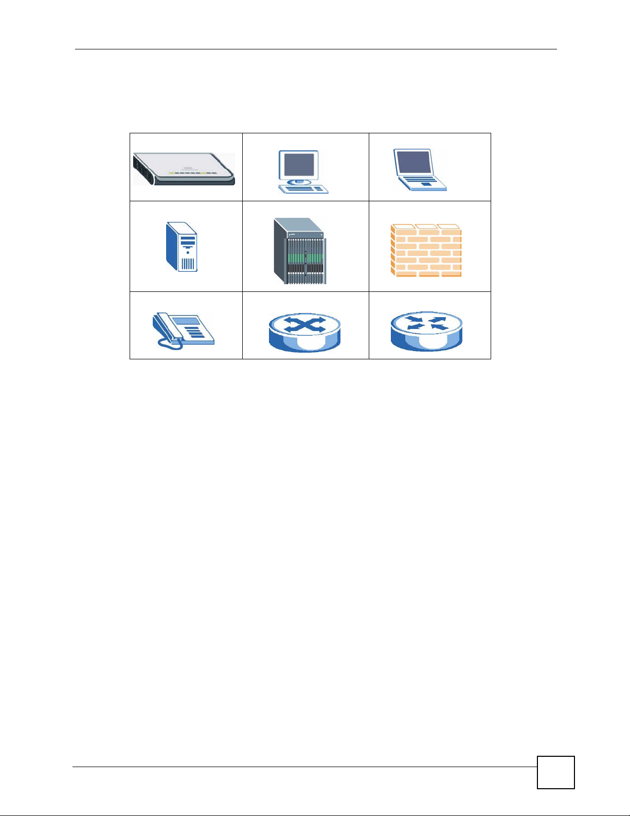
Icons Used in Figures
Figures in this User’s Guide may use the following generic icons. The STB icon is not an exact
representation of your STB.
STB Computer Notebook computer
Server DSLAM Firewall
Telephone Switch Router
STB-1001S2 User’s Guide
5
Page 6
Safety Warnings
• Do NOT use this product near water, for example, in a wet basement or near a swimming
• Do NOT expose your device to dampness, dust or corrosive liquids.
• Do NOT store things on the device.
• Do NOT install, use, or service this device during a thunderstorm. There is a remote risk
• Connect ONLY suitable accessories to the device.
• Do NOT open the device or unit. Opening or removing covers can expose you to
• Make sure to connect the cables to the correct ports.
• Place connecting cables carefully so that no one will step on them or stumble over them.
• Always disconnect all cables from this device before servicing or disassembling.
• Use ONLY an appropriate power adaptor or cord for your device. Connect it to the right
• Do NOT allow anything to rest on the power adaptor or cord and do NOT place the
• Do NOT use the device if the power adaptor or cord is damaged as it might cause
• If the power adaptor or cord is damaged, remove it from the device and the power source.
• Do NOT attempt to repair the power adaptor or cord. Contact your local vendor to order a
• Do not use the device outside, and make sure all the connections are indoors. There is a
• Do NOT obstruct the device ventilation slots, as insufficient airflow may harm your
• If you wall-mount your device, make sure that no electrical lines, gas or water pipes will
Safety Warnings
pool.
of electric shock from lightning.
dangerous high voltage points or other risks. ONLY qualified service personnel should
service or disassemble this device. Please contact your vendor for further information.
supply voltage (for example, 110V AC in North America or 230V AC in Europe).
product where anyone can walk on the power adaptor or cord.
electrocution.
new one.
remote risk of electric shock from lightning.
device.
be damaged.
6
This product is recyclable. Dispose of it properly.
STB-1001S2 User’s Guide
Page 7

Contents Overview
Contents Overview
Using the STB ........................................................................................................................15
Introducing the STB ...................................................................................................................17
The Menu System .....................................................................................................................21
Troubleshooting ..................................................... .................................................................... 31
Product Specifications ............................................................................................................... 35
Appendices and Index ...........................................................................................................39
STB-1001S2 User’s Guide
7
Page 8

Contents Overview
8
STB-1001S2 User’s Guide
Page 9

Table of Contents
Table of Contents
About This User's Guide..........................................................................................................3
Document Conventions............................................................................................................4
Safety Warnings ........................................................................................................................6
Contents Overview ...................................................................................................................7
Table of Contents......................................................................................................................9
List of Figures.........................................................................................................................11
List of Tables...........................................................................................................................13
Part I: Using the STB ............................................................................. 15
Chapter 1
Introducing the STB................................................................................................................17
1.1 Overview ............. .......................................................... ... .... ... ... .......................................... 17
1.2 LEDs ............................................................................................. ... .................................... 18
1.3 Rear Panel Connections ...................................................................................................... 18
1.4 Resetting the STB ........................................ ... ... .......................................................... ....... 19
Chapter 2
The Menu System ...................................................................................................................21
2.1 Navigating the Menus ......................................... .... ... ... ... .... ... ... ... ... .... ... ... ... .......................21
2.2 The Basic Setup Menus ..... ... .... ... ... ... ... .... ... ... ... .... .............................................................21
2.2.1 Accessing and Exiting the Basic Setup Menus ................... ....................................... 21
2.2.2 Video Setup Menu ...................................................................................................... 22
2.2.3 Audio Setup Menu ...................................................................................................... 23
2.2.4 System Setup Menu ................................................................................................... 24
2.2.5 Language Setup Menu ............................................................................................... 24
2.2.6 The Factory Default Menu ...................... ... .... ... .......................................................... 25
2.3 The Advanced Setup Menus ............................................................................................... 25
2.3.1 Accessing and Exiting the Menus .............................................................................. 25
2.3.2 The Advanced Setup: Information Menu ....... ... ... ....................................................... 26
2.3.3 The Advanced Setup: Network Menu ........................................................................ 27
2.3.4 The Advanced Setup: Firmware Upgrade Menu ........................................................ 29
STB-1001S2 User’s Guide
9
Page 10

Table of Contents
Chapter 3
Troubleshooting......................................................................................................................31
3.1 Power, Hardware Connections, and LEDs .......................................................................... 31
3.2 STB Access and Login ........................................................................................................32
3.3 Internet Access ................................... ... .... ... ... .......................................................... .......... 33
Chapter 4
Product Specifications...........................................................................................................35
4.1 General STB Specifications ... .... ... ... ... ... .... ... .......................................................... ... ... .... ...35
4.2 Power Adaptor Specifications .......... ... ... .... ............................................................. ... ..........37
Part II: Appendices and Index............................................................... 39
Appendix A Setting up Your Computer’s IP Address..............................................................41
Appendix B IP Addresses and Subnetting .............................................................................63
Appendix C Legal Information................................................................................................73
Index.........................................................................................................................................77
10
STB-1001S2 User’s Guide
Page 11

List of Figures
List of Figures
Figure 1 Application overview ................................................................................................................. 17
Figure 2 LEDs ......................................................................................................................................... 18
Figure 3 Rear Panel Connections ..........................................................................................................19
Figure 4 The Home Menu ....................................................................................................................... 22
Figure 5 The Video Setup Menu ............................................................................................................. 22
Figure 6 The Audio Setup Menu ............................................................................................................. 23
Figure 7 The System Setup Menu ............................ ................................................. ............................. 24
Figure 8 The Language Setup Menu ...................................................................................................... 25
Figure 9 The Factory Default Menu .............................. ................................................ .......................... 25
Figure 10 The Login Menu ..................................................................................................................... 26
Figure 11 The Information Menu ............................................................................................................26
Figure 12 The Network: DHCP Menu .................................................................................................... 27
Figure 13 The Network: Static IP Menu ................................................................................................. 28
Figure 14 The Network: PPPoE Menu ................................................................................................... 29
Figure 15 The Firmware Upgrade Menu ................................................................................................ 29
Figure 16 Firmware Upgrade Error ............................... ................... ................ .................... ................... 30
Figure 17 Wall-mounting Example .......................................................................................................... 38
Figure 18 Masonry Plug and M4 Tap Screw ........................................................................................... 38
Figure 19 WIndows 95/98/Me: Network: Configuration ....................................................... ... ... ... ... .... ... 42
Figure 20 Windows 95/98/Me: TCP/IP Properties: IP Address .............................................................. 43
Figure 21 Windows 95/98/Me: TCP/IP Properties: DNS Configuration ..................... ... ... .... ...................44
Figure 22 Windows XP: Start Menu ................. ....................................................................................... 45
Figure 23 Windows XP: Control Panel ............................................... .... ... ... ... ... .... ... ... ... .......................45
Figure 24 Windows XP: Control Panel: Network Connections: Properties ............................................. 46
Figure 25 Windows XP: Local Area Connection Properties ................................................................... 46
Figure 26 Windows XP: Internet Protocol (TCP/IP) Properties .............................................................. 47
Figure 27 Windows XP: Advanced TCP/IP Properties .............. ... ... ... .... ... ... ... ... .... ... ... ... ....................... 48
Figure 28 Windows XP: Internet Protocol (TCP/IP) Properties .............................................................. 49
Figure 29 Windows Vista: Start Menu .....................................................................................................50
Figure 30 Windows Vista: Control Panel .................. .... ... ... ... .... ... ... ... .... ... ... ... ... .... ................................ 50
Figure 31 Windows Vista: Network And Internet .................................................................................... 50
Figure 32 Windows Vista: Network and Sharing Center ............................................................ ... ... .... ... 50
Figure 33 Windows Vista: Network and Sharing Center ............................................................ ... ... .... ... 51
Figure 34 Windows Vista: Local Area Connection Properties ............................ .... ... ... ... .... ... ... ... ... .... ... 51
Figure 35 Windows Vista: Internet Protocol Version 4 (TCP/IPv4) Properties ....................................... 52
Figure 36 Windows Vista: Advanced TCP/IP Properties .............................. .......................................... 53
Figure 37 Windows Vista: Internet Protocol Version 4 (TCP/IPv4) Properties ....................................... 54
Figure 38 Macintosh OS 8/9: Apple Menu .............................................................................................. 55
STB-1001S2 User’s Guide
11
Page 12

List of Figures
Figure 39 Macintosh OS 8/9: TCP/IP .....................................................................................................55
Figure 40 Macintosh OS X: Apple Menu ................................................................................................56
Figure 41 Macintosh OS X: Network ......................................................................................................57
Figure 42 Red Hat 9.0: KDE: Network Configuration: Devices ............................................................. 58
Figure 43 Red Hat 9.0: KDE: Ethernet Device: General ...................................................................... 58
Figure 44 Red Hat 9.0: KDE: Network Configuration: DNS ................................................................... 59
Figure 45 Red Hat 9.0: KDE: Network Configuration: Activate ............................................................ 59
Figure 46 Red Hat 9.0: Dynamic IP Address Setting in ifconfig-eth0 ................................................... 60
Figure 47 Red Hat 9.0: Static IP Address Setting in ifconfig-eth0 ... .... ... ... ... ... .... ... ... ... .... ... ... ... ... .... ... 60
Figure 48 Red Hat 9.0: DNS Settings in resolv.conf ............................................................................ 60
Figure 49 Red Hat 9.0: Restart Ethernet Card .....................................................................................60
Figure 50 Red Hat 9.0: Checking TCP/IP Properties ........................................................................... 61
Figure 51 Network Number and Host ID ...... ... ... ... ... .... .......................................................... ... .............64
Figure 52 Subnetting Example: Before Subnetting ................................................................................66
Figure 53 Subnetting Example: After Subnetting ................................................................................... 67
Figure 54 Conflicting Computer IP Addresses Example ........................................................................ 71
Figure 55 Conflicting Computer IP Addresses Example ........................................................................ 71
Figure 56 Conflicting Computer and Router IP Addresses Example .. .... ... ... ... ... .... ................................ 72
12
STB-1001S2 User’s Guide
Page 13

List of Tables
List of Tables
Table 1 LEDs ......................................................................................................................................... 18
Table 2 Rear Panel Connections ...........................................................................................................19
Table 3 The Video Setup Menu ............................................................................................................. 23
Table 4 The Audio Setup Menu ............................................................................................................. 24
Table 5 The System Setup Menu ..........................................................................................................24
Table 6 The Information Menu ............................................................................................................... 26
Table 7 The Network: DHCP Menu .......................................................................................................27
Table 8 The Network: Static IP Menu .................................................................................................... 28
Table 9 The Network: PPPoE Menu ......................................................................................................29
Table 10 Hardware Specifications ......................................................................................................... 35
Table 11 Firmware Specifications ...................................... ... .... ... ... ... .... ... ... ... ....................................... 36
Table 12 Standards Supported ..............................................................................................................36
Table 13 Power Adaptor Specifications ................................................................................................. 37
Table 14 IP Address Network Number and Host ID Example ............................................ ... ... ... ... .... ... 64
Table 15 Subnet Masks ......................................................................................................................... 65
Table 16 Maximum Host Numbers ................................. ... ... .... ... ... ... .... ... ... ... ... .... ... ... ... .... ... ... ... ..........65
Table 17 Alternative Subnet Mask Notation ........................................................................................... 65
Table 18 Subnet 1 ..................................................................................................................................67
Table 19 Subnet 2 ..................................................................................................................................68
Table 20 Subnet 3 ..................................................................................................................................68
Table 21 Subnet 4 ..................................................................................................................................68
Table 22 Eight Subnets ................................................................ ... ....................................................... 68
Table 23 24-bit Network Number Subnet Planning ......... ... ............................................................. .... ...69
Table 24 16-bit Network Number Subnet Planning ......... ... ............................................................. .... ...69
STB-1001S2 User’s Guide
13
Page 14

List of Tables
14
STB-1001S2 User’s Guide
Page 15

PART I
Using the STB
Introducing the STB (17)
The Menu System (21)
Troubleshooting (31)
Product Specifications (35)
15
Page 16

16
Page 17
CHAPTER 1
Introducing the STB
This chapter introduces the main applications and features of the STB. It also introduces the
ways in which you can manage the STB.
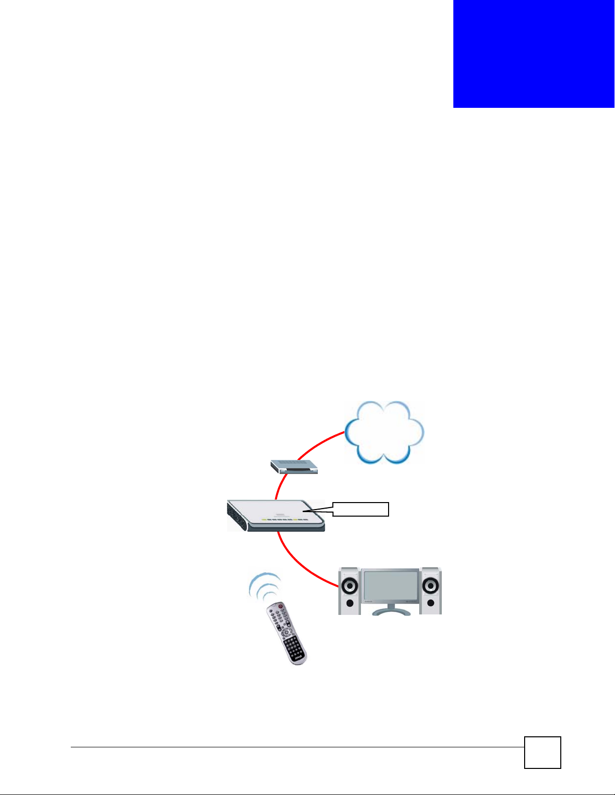
1.1 Overview
Your STB is an IP Set-Top Box. Use it to watch Internet Television (IPTV) and Video on
Demand (VOD) on your television. Connect the STB to your regular Internet access device (a
broadband modem or router , for ex ample). Operate the STB using the supplied remote control.
The following figure shows your STB (A) connected to your Internet access device (B)
supplying content from the service provider on the Internet to your TV (C), operated by the
remote control (D).
Figure 1 Application overview
A
D
INTERNET
B
STB
C
STB-1001S2 User’s Guide
17
Page 18
Chapter 1 Introducing the STB
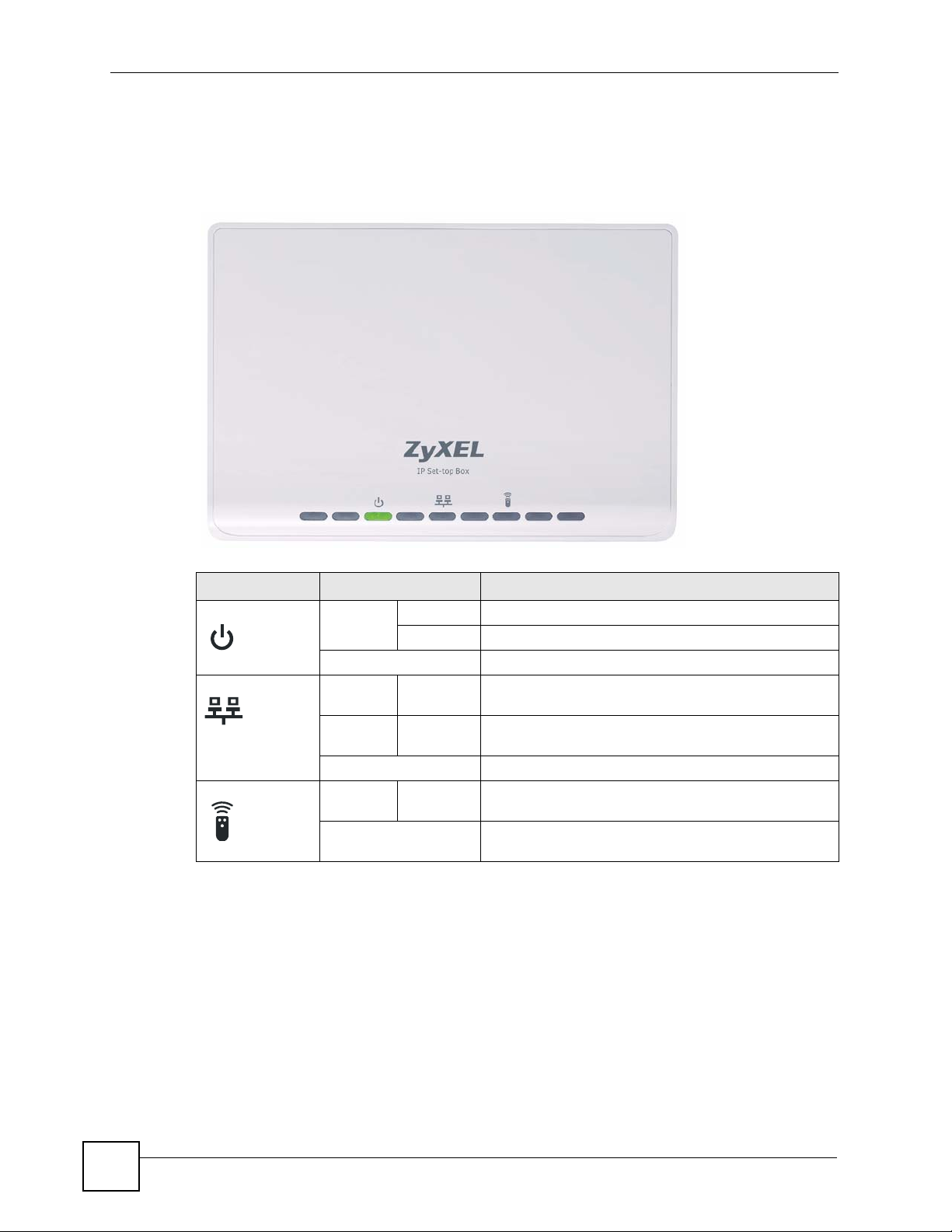
1.2 LEDs
This section describes the LEDs (lights) on the front of the STB.
Figure 2 LEDs
Table 1 LEDs
LED STATUS DESCRIPTION
POWER On Blinking The STB is starting up, or is in standby mode.
Green The STB is on and ready to use.
Off The STB is not receiving power, or has malfunctioned.
LAN On Green The STB has an Ethernet conn ection to the network on
Blinking Green The STB has an Ethernet connection to the network on
Off The STB has no network connection on the LAN port.
REMOTE Blinking Green The Infra-red receiver on the front of the STB is
Off The Infra-red receiver on the front of the STB is not
1.3 Rear Panel Connections
This section describes the rear of the STB.
the LAN port.
the LAN port, and is transmitting or receiving data.
receiving signals from the remote control.
receiving signals from the remote control.
18
STB-1001S2 User’s Guide
Page 19
Chapter 1 Introducing the STB
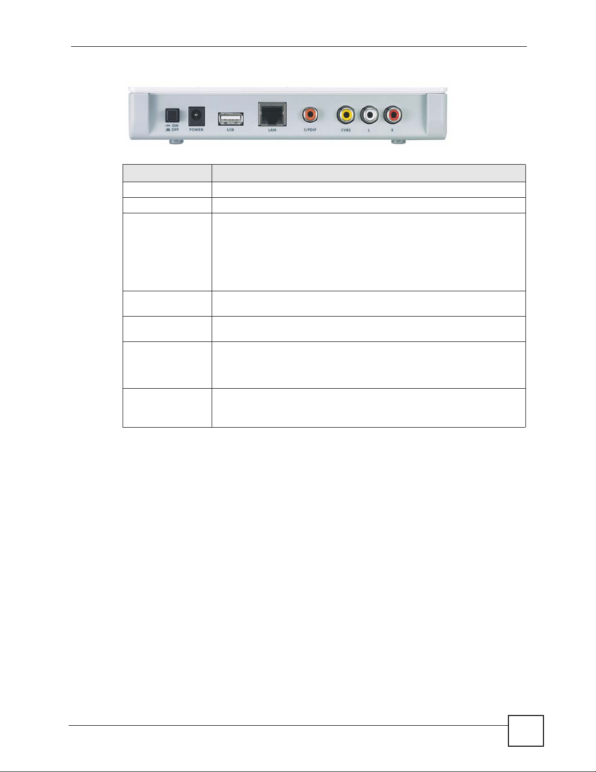
Figure 3 Rear Panel Connections
Table 2 Rear Panel Connections
LABEL DESCRIPTION
ON/OFF Use this switch to turn the STB on or off.
POWER Connect this port to a suitable power supply using the provided adaptor.
USB Use this port to connect to a USB mouse or keyboard (not supplied).
Note: The output power from your USB mouse or keyboard must
not exceed 200 mA. You should check this from the power
rating label or User’s Guide of the mouse or keyboard in
advance.
LAN Use this Ethernet port to connect the STB to your Internet access device or
network.
S/PDIF Use this port to connect the STB to an S/PDIF (Sony / Philips Digital Interface
Format) audio device.
CVBS Use this composite video RCA connector to connect the STB to your TV’s
L, R Use these to connect the STB to your audio device’s analog audio inputs.
analog video input (usually colored yellow).
The composite video connector does not carry audio. You must also connect
your TV to one of the STB’s audio connectors.
L: The white RCA connector carries the stereo audio signal (left channel).
R: The red RCA connector carries the stereo audio signal (right channel).
1.4 Resetting the STB
T o reset the STB to its factory defaults, use the System Setup menu (see Section 2.2.4 on page
24).
STB-1001S2 User’s Guide
19
Page 20

Chapter 1 Introducing the STB
20
STB-1001S2 User’s Guide
Page 21

CHAPTER 2
The Menu System
This chapter discusses the STB’s menus. These menus are displayed on the screen of the
television connected to the STB, and operated using the STB’s remote control.
• Use the Basic Setup menus to make basic changes to the STB’s configuration (such as
activating Daylight Saving Time or selecting the video mode).
• Use the Advanced Setup menus to make advanced changes to the STB’s configuration
(such as setting the STB’s homepage or changing its IP address).
2.1 Navigating the Menus
• Each menu has two columns. On the left, you can select the setup menu you want to see,
and on the right you can change the menu’s settings.
• Use the and navigator keys on the remote control to move between the two columns.
• Use the and navigator keys on the remote control to highlight the menu or setting you
want.
• The currently-highlighted item is colored orange.
• Use the OK key on the remote control to select the highlighted object.
• When you go to a new menu, the top item in the right-hand column is automatically
highlighted. To move to the left-hand column, press the key.
• Highlight and select the Save button in each menu to store the changes you configure.
2.2 The Basic Setup Menus
Use the Basic Setup menus to configure how the STB shows media, to turn Daylight Saving
Time on or off, or to reset the STB. Use the remote control to navigate the menu system.
2.2.1 Accessing and Exiting the Basic Setup Menus
Take the following steps to access the Basic Setup menus.
1 Make sure the network is connected.
If you are not sure whether the network is connected or not, press the HOME key on the
remote control. If the Home menu displays normally, the STB is properly connected.
STB-1001S2 User’s Guide
21
Page 22
Chapter 2 The Menu System
Figure 4 The Home Menu
2 Press the MENU key on the remote control. The Video Setup menu displays (see
Section 2.2.2 on page 22).
To leave the basic setup menus, press the HOME key on the remote control at any time. The
Home menu displays.
" Changes do not take effect until you save them. Each menu has a Save
button.
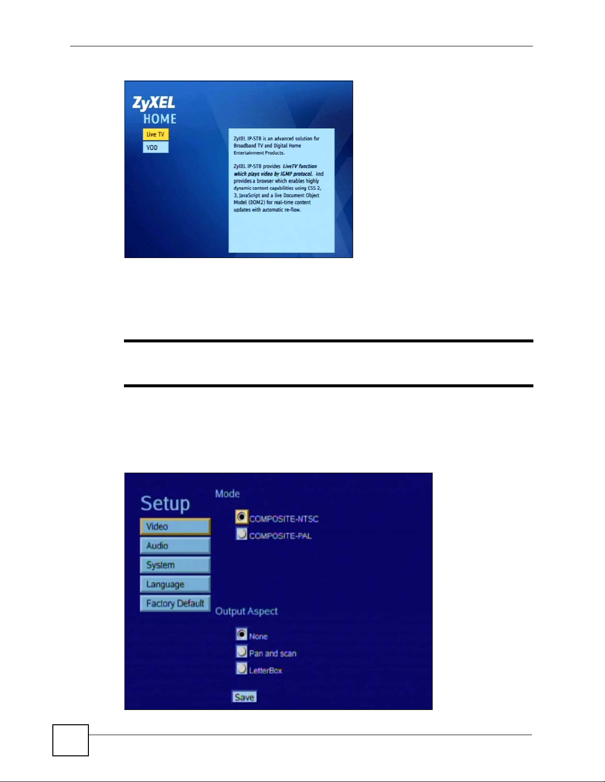
2.2.2 Video Setup Menu
Use the Video Se tup menu to change the STB’s display type.
Figure 5 The Video Setup Menu
22
STB-1001S2 User’s Guide
Page 23
Chapter 2 The Menu System
" Do not change the Mode in this menu! If you do so, the picture on your TV
may not display correctly. NTSC is supported in North American televisions,
and PAL is supported in European televisions.
The following table describes the labels in this menu.
Table 3 The Video Setup Menu
LABEL DESCRIPTION
Mode COMPOSITE-NTSC Select this if your TV supports NTSC (Common in
COMPOSITE-PAL Select this if your TV supports PAL (common in
Output
Aspect
Save Select this to store your changes. You may need to
None Select this to display images without changing their
Pan and scan Select this to watch TV or video with a 4:3 aspect ratio
LetterBox Select this to watch TV or video with a 16:9 aspect
North and Central America and Japan).
Europe and most of the world).
shape.
(traditional television).
ratio (widescreen).
reboot your STB (use the ON/OFF hardware switch)
before the new settings are used.
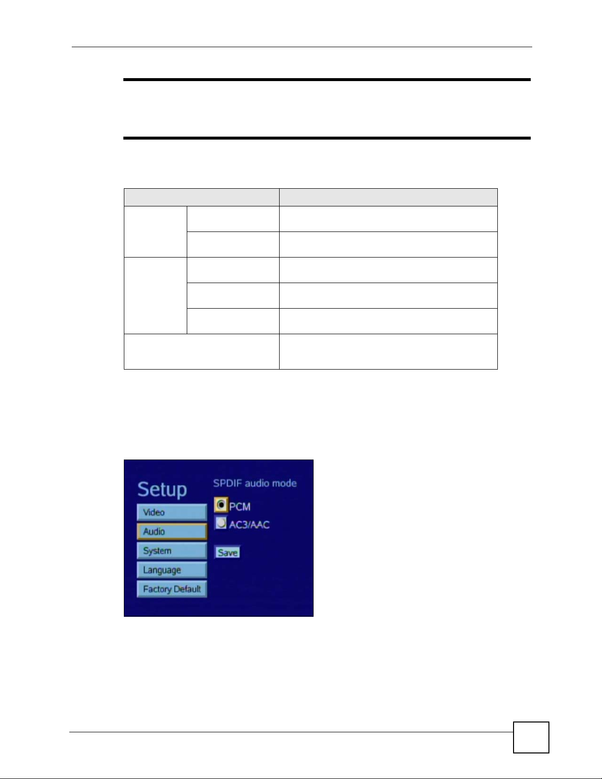
2.2.3 Audio Setup Menu
Use the Audio menu to change the STB’s digital audio output type (analog audio output is
unaffected).
Figure 6 The Audio Setup Menu
STB-1001S2 User’s Guide
23
Page 24
Chapter 2 The Menu System
The following table describes the labels in this screen.
Table 4 The Audio Setup Menu
LABEL DESCRIPTION
PCM Select this to use PCM (Pulse Code Modulation) audio
compression. Select this only if your TV or audio eq u i pm ent
(connected to the STB’s S/PDIF connector) also supports PCM.
AC3/AAC Select this to use AC-3 (Dolby Digital) or AAC (Advanced Audio
Coding) audio compression. Select this only if your TV or audio
equipment (connected to the STB’s S/PDIF connector) also
supports AC-3 or AAC compression.
Save Select this to store your changes. You may need to reboot your
STB (use the ON/OFF hardware switch) before the new settings
are used.
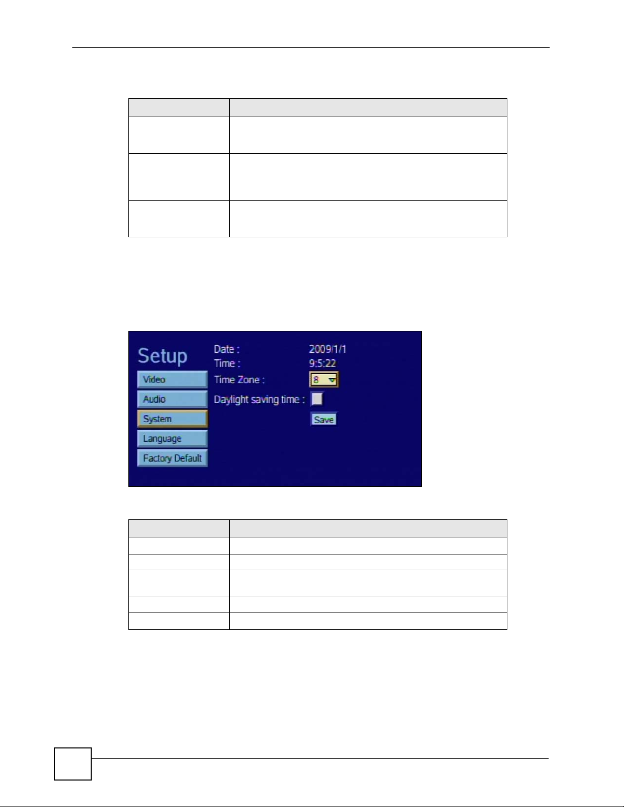
2.2.4 System Setup Menu
Use the System Setup menu to check the STB’s date and time settings, change the time zone,
and activate or deactivate Daylight Saving Time.
Figure 7 The System Setup Menu
The following table describes the labels in this menu.
Table 5 The System Setup Menu
LABEL DESCRIPTION
Date This is the current date. This comes from an external time server.
Time This is the current time. This comes from an external time server.
Time Zone Select your time zone from the list. In the list, 0 is GMT (Greenwich
Mean Time) so, for example, 8 is GMT plus eight hours.
Daylight Saving Time Select this when Daylight Saving Time is in effect.
Save Select this to store your configuration changes.
2.2.5 Language Setup Menu
Use this menu to select the STB’s operating language. At the time of writing, only English is
supported.
24
STB-1001S2 User’s Guide
Page 25

Figure 8 The Language Setup Menu
2.2.6 The Factory Default Menu
Use this screen to return the STB to its default settings.
Figure 9 The Factory Default Menu
Chapter 2 The Menu System
Click Factory Default to return the STB to its original settings. Any configuration changes
you made will be lost.
2.3 The Advanced Setup Menus
The Advanced Setup menus allow you to see and change network settings.
1 DO NOT use this section unless you have been specifically told to by the
service provider! Misconfiguration of the menus in this section could render
your STB unusable. If in doubt, contact the service provider.
2.3.1 Accessing and Exiting the Menus
Take the following steps to access the Advanced Setup menus.
STB-1001S2 User’s Guide
25
Page 26

Chapter 2 The Menu System
1 Ensure that the STB is set up and working correctly, as shown in the Quick Start Guide.
2 Press Menu to enter the menu system.
3 Press the blue key on the remote controller three times. The Login menu displays.
Figure 10 The Login Menu
4 Enter the password. The default password is “123456”.
5 Press the navigator key to highlight the login button. Press the OK key.
The Advanced Setup: Information menu displays when you are successfully logged in.
2.3.2 The Advanced Setup: Information Menu
Use this menu to see information about the STB’s current network and configuration settings.
Select Information from the column on the left of the screen. The following menu displays.
Figure 11 The Information Menu
The following table describes the labels in this menu.
Table 6 The Information Menu
LABEL DESCRIPTION
Date This shows the current date configured on the STB.
CPU This shows the Central Processing Unit’s product code.
Flash This shows the quantity of available flash (non-volatile) memory.
Memory This shows the quantity of available run-time memory.
26
STB-1001S2 User’s Guide
Page 27

Table 6 The Information Menu
LABEL DESCRIPTION
MAC Address This shows the hardware Media Access Control address of the
STB.
IP Address This shows the IP address currently assigned to the STB. You can
change this in the Advanced Setup: Network menu.
STB Version This shows the firmware version running on the STB. Check this
before you upload new firmware.
Bootloader This shows the version number of the software that loads the
STB’s operating system on startup.
Kernel This shows the version number of the code that controls the STB’s
basic operations.
Rootfs This shows the version number of the STB’s filesystem code.
Apps This shows the version number of the STB’s software applications.
2.3.3 The Advanced Setup: Network Menu
Use this menu to set up the STB’s IP address, media server information, and homepage.
This menu differs according to the Mode you select.
Chapter 2 The Menu System
• Select DHCP to have the STB obtain a dynamic IP address automatically from a DHCP
server. See Section 2.3.3.1 on page 27. DHCP is the default setting.
• Select Static to assign an IP address to the STB. See Section 2.3.3.2 on page 28.
• Select PPPoE to use a Point-to-Point Protocol over Ethernet service. See Section 2.3.3.3
on page 29.
2.3.3.1 Network: DHCP
Select DHCP in the Network menu. The following menu displays.
Figure 12 The Network: DHCP Menu
The following table describes the labels in this menu.
Table 7 The Network: DHCP Menu
LABEL DESCRIPTION
Mode Select DHCP to have the STB obtain an IP address automatically .
STB Server Enter the IP address of the media server which supplies TV and
video to the STB.
STB-1001S2 User’s Guide
27
Page 28

Chapter 2 The Menu System
Table 7 The Network: DHCP Menu
LABEL DESCRIPTION
Home URL Enter the address of the homepage the STB uses as the Home
menu (the screen that displays when you press the HOME key on
the remote control).
ACS Server This field is for remote management. Change the information in
this field only if you were specifically told to do so.
Enter the address of the auto-configuration server from which the
STB gets its operating settings.
NTP Server Enter the address of the Network Time Protocol server from which
Save Select this to store your configuration changes.
the STB gets its date and time settings.
2.3.3.2 Network: Static IP Address
Select Static in the Network menu. The following menu displays.
Figure 13 The Network: Static IP Menu
28
The following table describes the labels in this menu that were not already described in table 7.
Table 8 The Network: Static IP Menu
LABEL DESCRIPTION
Mode Select St atic to give the STB a specific IP address.
STB IP Enter the IP address you want to assign to the STB.
Subnet Mask Enter the subnet mask of the STB’s IP address.
Gateway Enter the IP address of the network gateway.
Primary DNS Enter the IP address of the primary Domain Name Server. DNS
allows your STB to resolve domain names (such as zyxel.com) into
IP addresses.
Secondary DNS Enter the IP address of the secondary (backup) Domain Name
Server.
STB-1001S2 User’s Guide
Page 29

2.3.3.3 Network: PPPoE
Select PPPoE in the Network menu. The following menu displays.
Figure 14 The Network: PPPoE Menu
The following table describes the labels in this menu that were not already described in table 7.
Table 9 The Network: PPPoE Menu
LABEL DESCRIPTION
Mode Select PPPoE to use a Point-to-Point Protocol over Ethernet
User Name Enter the username for your PPPoE account.
Password Enter the password for your PPPoE account.
Chapter 2 The Menu System
service.
2.3.4 The Advanced Setup: Firmware Upgrade Menu
Use this menu to get new firmware from the autoconfiguration server. You must be connected
to the network and have a valid autoconfiguration server address configured in the Advanced
Setup: Network menu’s ACS Server field (see Section 2.3.3 on page 27).
Select Firmware Upgrade from the column on the left of the screen. The following menu
displays.
Figure 15 The Firmware Upgrade Menu
STB-1001S2 User’s Guide
29
Page 30

Chapter 2 The Menu System
If you want to get new firmware from the auto-configuration server, click Upgrade Now. The
STB contacts the autoconfiguration server and downloads the firmware.
If the following screen displays, the STB cannot reach the autoconfiguration server. Check the
settings in the Advanced Setup: Network menu (see Section 2.3.3 on page 27) and try again.
Figure 16 Firmware Upgrade Error
30
STB-1001S2 User’s Guide
Page 31

CHAPTER 3
Troubleshooting
This chapter offers some suggestions to solve problems you might encounter. The potential
problems are divided into the following categories.
• Power, Hardware Connections, and LEDs
• STB Access and Login
• Internet Access
3.1 Power, Hardware Connections, and LEDs
V The STB does not turn on. None of the LEDs turn on.
1 Make sure the STB is turned on.
2 Make sure you are using the power adaptor or cord included with the STB.
3 Make sure the power adaptor or cord is connected to the STB and plugged in to an
appropriate power source. Make sure the power source is turned on.
4 Turn the STB off and on.
5 If the problem persists, contact the vendor.
V The POWER ( ) LED is red, or blinking green.
1 The STB may be in standby mode. T ry u sing the remote contro l’s button to turn it on.
2 Wait for a short while. The STB may take a minute or so to start up.
3 If the LED still does not turn steady green, turn the STB off and on.
4 If the problem persists, contact the vendor.
V One of the LEDs does not behave as expected.
1 Make sure you understand the normal behavior of the LED. See Section 1.2 on page 18.
STB-1001S2 User’s Guide
31
Page 32

Chapter 3 Troubleshooting
2 Check the hardware connections. See the Quick Start Guide and Section 1.3 on page 18.
3 Inspect your cables for damage. Contact the vendor to replace any damaged cables.
4 Turn the STB off and on.
5 If the problem persists, contact the vendor.
V I cannot operate the STB using the remote control.
1 See your Quick Start Guide for instructions on using the remote control.
2 If the REMOTE (
remote control’s batteries may be improperly inserted or dead. Check they are properly
inserted, or try replacing them.
3 Move closer to the STB and try again.
4 If the problem persists, contact your vendor.
3.2 STB Access and Login
) LED does not blink when you press a remote control button, the
V I forgot the IP address for the STB.
The default IP address is 192.168.1.1. Use the System Setup menu to check the current IP
address (see Section 2.2.4 on page 24).
V I forgot the password for the Advanced menus.
1 The default password is 123456.
V I cannot see or access the Login menu.
1 Make sure the LEDs are behaving as expected. See the Quick Start Guide and Section
1.2 on page 18.
2 If the problem continues, contact the vendor.
32
STB-1001S2 User’s Guide
Page 33

3.3 Internet Access
V I cannot access IPTV or VOD services.
1 Check the hardware connections, and make sure the LEDs are behaving as expected. See
the Quick Start Guide and Section 1.2 on page 18. Ensure that your Internet access
device is working correctly.
2 Check the Home URL IP address in the Network menu.
3 Disconnect all the cables from your STB, and follow the directions in the Quick Start
Guide again.
4 If the problem continues, contact your ISP or IPTV provider.
V The Internet connection is slow or intermittent.
Chapter 3 Troubleshooting
There might be a lot of traffic on the network. If you have computers or other devices usin g
your Internet connection, try turning them off or disconnecting them. If your Internet access
device uses bandwidth management, try reconfiguring it to allow the STB higher throughput.
STB-1001S2 User’s Guide
33
Page 34

Chapter 3 Troubleshooting
34
STB-1001S2 User’s Guide
Page 35

CHAPTER 4
Product Specifications
This chapter gives details about your STB’s hardware and firmware features.
4.1 General STB Specifications
The following tables summarize the STB’s hardware and firmware features.
Table 10 Hardware Specifications
SPECIFICATION DESCRIPTION
Dimensions (W x D x H) 190 x 130.6 x 34.8 mm
Weight 0.35 Kg
Power DC: 12 V, 1.5 A
LAN Ethernet Port Auto-negotiating: 10 Mbps or 100 Mbps in either half-duplex or full-duplex
mode.
Auto-crossover: Use either crossover or straight-through Ethernet cables.
SPDIF Port Sony / Philips Digital Interface Format (IEC 958 type II) audio connector.
USB Port Universal Serial Bus 2.0 connector.
Composite Video Port 1 x CVBS RCA-type connector.
Supported video standards:
•PAL
•NTSC
Analog Audio Ports 1 x stereo left channel RCA-type connector.
1 x stereo right channel RCA-type connector.
LEDs POWER
LAN
REMOTE
Operating Environment Temperature: 0º C ~ 40º C
Storage Environment Temperature: -40º C ~ 55º C
STB-1001S2 User’s Guide
Humidity: 0% ~ 95% RH
Humidity: 0% ~ 95% RH
35
Page 36

Chapter 4 Product Specifications
Table 10 Hardware Specifications
SPECIFICATION DESCRIPTION
Approvals Safety
Distance between wallmounting holes on
device’s base panel
Screw size for wall
mounting
Table 11 Firmware Specifications
FEATURE DESCRIPTION
Default IP Address Obtained via DHCP
Default Subnet Mask Obtained via DHCP
Default Password 123456
Device Management Use the remote control and the on-screen menu system to configure the
Time and Date Get the current time and date from an external server when you turn on
PPPoE PPPoE mimics a dial-up Internet access connection.
UL60950-1
CAN/CSA-C22.2 No.60950-1-03
EN60950-1
IEC 60950-1
EMC
FCC Part 15 Class B
EN55022 Class B
EN55024
137 mm
M4 Tap
STB.
your STB.
The following list, which is not exhaustive, illustrates the standards supported in the STB.
Table 12 Standards Supported
STANDARD DESCRIPTION
RFC 867 Daytime Protocol
RFC 868 Time Protocol.
RFC 1058 RIP-1 (Routing Information Protocol)
RFC 1112 IGMP v1
RFC 1157 SNMPv1: Simple Network Management Protocol version 1
RFC 1305 Network Time Protocol (NTP version 3)
RFC 1441 SNMPv2 Simple Network Management Protocol version 2
RFC 1483 Multiprotocol Encapsulation over ATM Adaptation Layer 5
RFC 1661 The Point-to-Point Protocol (PPP)
RFC 1723 RIP-2 (Routing Information Protocol)
RFC 1901 SNMPv2c Simple Network Management Protocol version 2c
RFC 2236 Internet Group Management Protocol, Version 2.
RFC 2408 Internet Security Association and Key Management Protocol (ISAKMP)
RFC 2516 A Method for Transmitting PPP Over Ethernet (PPPoE)
36
STB-1001S2 User’s Guide
Page 37

Table 12 Standards Supported (continued)
STANDARD DESCRIPTION
RFC 2684 Multiprotocol Encapsulation over ATM Adaptation Layer 5.
IEEE 802.11d Standard for Local and Metropolitan Area Networks: Media Access
Control (MAC) Bridges
TR-069 TR-069 DSL Forum Standard for CPE Wan Management.
1.363.5 Compliant AAL5 SAR (Segmentation And Re-assembly)
4.2 Power Adaptor Specifications
Table 13 Power Adaptor Specifications
AC Power Adaptor Model MU18-2120150-A1
Input Power 100~240 Volts AC / 50~60 Hz / 0.6A
Output Power 12 Volts DC / 1.5 A
Safety Standards UL (UL60950-1)
Chapter 4 Product Specifications
CUL (CSA C22.2 No.60950-1-03)
Wall-mounting Instructions
" It is recommended that you do NOT wall-mount the STB. Wall-mounting kit is
not included.
Complete the following steps to hang your STB on a wall.
" See Table 10 on page 35 for the size of screws to use and how far apart to place
them.
1 Select a position free of obstructions on a sturdy wall.
2 Drill two holes for the screws.
1 Be careful to avoid damaging pipes or cables located inside the wall when
drilling holes for the screws.
STB-1001S2 User’s Guide
37
Page 38

Chapter 4 Product Specifications
3 Do not insert the screws all the way into the wall. Leave a small gap of about 0.5 cm
between the heads of the screws and the wall.
4 Make sure the screws are snugly fastened to the wall. They need to hold the weight of
the STB with the connection cables.
5 Align the holes on the back of the STB with the screws on the wall. Hang the STB on the
screws.
Figure 17 Wall-mounting Example
The following are dimensions of an M4 tap screw and masonry plug used for wall mounting.
All measurements are in millimeters (mm).
Figure 18 Masonry Plug and M4 Tap Screw
38
STB-1001S2 User’s Guide
Page 39

PART II
Appendices and
Index
" The appendices provide general information. Some details may not apply to
your STB.
Setting up Your Computer’s IP Address (41)
IP Addresses and Subnetting (63)
Legal Information (73)
Customer Support (77)
Index (77)
39
Page 40

40
Page 41

APPENDIX A
Setting up Your Computer’s IP
Address
All computers must have a 10M or 100M Ethernet adapter card and TCP/IP installed.
Windows 95/98/Me/NT/2000/XP/Vista, Macintosh OS 7 and later operating systems and all
versions of UNIX/LINUX include the software components you need to install and use TCP/
IP on your computer. Windows 3.1 requires the purchase of a third-party TCP/IP application
package.
TCP/IP should already be installed on computers using Win dows NT/2000/XP, Macintosh OS
7 and later operating systems.
After the appropriate TCP/IP components are installed, configure the TCP/IP settings in order
to "communicate" with your network.
If you manually assign IP information instead of using dynamic assignment, make sure that
your computers have IP addresses that place them in the same subnet as the STB’s LAN port.
Windows 95/98/Me
Click Start, Settings, Control Panel and double-click the Network icon to open the Network
window.
STB-1001S2 User’s Guide
41
Page 42

Appendix A Setting up Your Computer’s IP Address
Figure 19 WIndows 95/98/Me: Network: Configuration
Installing Components
The Network window Configuration tab displays a list of installed components. You need a
network adapter, the TCP/IP protocol and Client for Microsoft Networks.
If you need the adapter:
1 In the Network window, click Add.
2 Select Adapter and then click Add.
3 Select the manufacturer and model of your network adapter and then click OK.
If you need TCP/IP:
1 In the Network window, click Add.
2 Select Protocol and then click Add.
3 Select Microsoft from the list of manufacturers.
4 Select TCP/IP from the list of network protocols and then click OK.
If you need Client for Microsoft Networks:
1 Click Add.
2 Select Client and then click Add.
3 Select Microsoft from the list of manufacturers.
4 Select Client for Microsoft Networks from the list of network clients and then click
OK.
5 Restart your computer so the changes you made take effect.
42
STB-1001S2 User’s Guide
Page 43

Configuring
Figure 20 Windows 95/98/Me: TCP/IP Properties: IP Address
Appendix A Setting up Your Computer’s IP Address
1 In the Network window Configuration tab, select your network adapter's TCP/IP entry
and click Properties
2 Click the IP Address tab.
• If your IP address is dynamic, select Obtain an IP address automatically.
• If you have a static IP address, select Specify an IP address and type your
information into the IP Address and Subnet Mask fields.
3 Click the DNS Configuration tab.
• If you do not know your DNS information, select Disable DNS.
• If you know your DNS information, select Enable DNS and type the information in
the fields below (you may not need to fill them all in).
STB-1001S2 User’s Guide
43
Page 44

Appendix A Setting up Your Computer’s IP Address
Figure 21 Windows 95/98/Me: TCP/IP Properties: DNS Configuration
4 Click the Gateway tab.
• If you do not know your gateway’s IP address, remove previously installed gateways.
• If you have a gateway IP address, type it in the New gateway field and click Add.
5 Click OK to save and close the TCP/IP Properties window.
6 Click OK to close the Network window. Insert the Windows CD if prompted.
7 Turn on your STB and restart your computer when prompted.
Verifying Settings
1 Click Start and then Run.
2 In the Run window, type "winipcfg" and then click OK to open the IP Configuration
window.
3 Select your network adapter. You should see your computer's IP address, subnet mask
and default gateway.
Windows 2000/NT/XP
The following example figures use the default Windows XP GUI theme.
1 Click start (Start in Windows 2000/NT), Settings, Control Panel.
44
STB-1001S2 User’s Guide
Page 45

Figure 22 Windows XP: Start Menu
Appendix A Setting up Your Computer’s IP Address
2 In the Control Panel, double-click Network Connections (Network and Dial-up
Connections in Windows 2000/NT).
Figure 23 Windows XP: Control Panel
3 Right-click Local Area Connection and then click Properties.
STB-1001S2 User’s Guide
45
Page 46

Appendix A Setting up Your Computer’s IP Address
Figure 24 Windows XP: Control Panel: Network Connections: Properties
4 Select Internet Protocol (TCP/IP) (under the General tab in Wi n XP ) and then click
Properties.
Figure 25 Windows XP: Local Area Connection Properties
5 The Internet Protocol TCP/IP Pr operties window opens (the General tab in W indows
XP).
• If you have a dynamic IP address click Obtain an IP address automatically.
• If you have a static IP address click Use the following IP Address and fill in the IP
address, Subnet mask, and Default gateway fields.
• Click Advanced.
46
STB-1001S2 User’s Guide
Page 47

Appendix A Setting up Your Computer’s IP Address
Figure 26 Windows XP: Internet Protocol (TCP/IP) Properties
6 If you do not know your gateway's IP address, remove any previously installed
gateways in the IP Settings tab and click OK.
Do one or more of the following if you want to configure additional IP addresses:
•In the IP Settings tab, in IP addresses, click Add.
•In TCP/IP Address, type an IP address in IP address and a subnet mask in Subnet
mask, and then click Add.
• Repeat the above two steps for each IP address you want to add.
• Configure additional default gateways in the IP Settings tab by clicking Add in
Default gateways.
•In TCP/IP Gateway Address, type the IP address of the default gateway in Gateway.
To manually configure a default metric (the number of transmission hops), clear the
Automatic metric check box and type a metric in Metric.
• Click Add.
• Repeat the previous three steps for each default gateway you want to add.
• Click OK when finished.
STB-1001S2 User’s Guide
47
Page 48

Appendix A Setting up Your Computer’s IP Address
Figure 27 Windows XP: Advanced TCP/IP Properties
7 In the Internet Protocol TCP/IP Properties window (the General tab in Windows
XP):
• Click Obtain DNS server address automatically if you do not know your DNS
server IP address(es).
• If you know your DNS server IP address(es), click Use the following DNS server
addresses, and type them in the Preferred DNS server and Alternate DNS server
fields.
If you have previously configured DNS servers, click Advanced and then the DNS
tab to order them.
48
STB-1001S2 User’s Guide
Page 49

Appendix A Setting up Your Computer’s IP Address
Figure 28 Windows XP: Internet Protocol (TCP/IP) Properties
8 Click OK to close the Internet Protocol (TCP/IP) Properties window.
9 Click Close (OK in Windows 2000/NT) to close the Local Area Connection
Properties window.
10 Close the Network Connections window (Network and Dial-up Connections in
Windows 2000/NT).
11 Turn on your STB and restart your computer (if prompted).
Verifying Settings
1 Click Start, All Programs, Accessories and then Command Prompt.
2 In the Command Prompt window, type "ipconfig" and then press [ENTER]. You can
also open Network Connections, right-click a network connection, click Status and
then click the Support tab.
Windows Vista
This section shows screens from Windows Vista Enterprise Version 6.0.
1 Click the Start icon, Control Panel.
STB-1001S2 User’s Guide
49
Page 50

Appendix A Setting up Your Computer’s IP Address
Figure 29 Windows Vista: Start Menu
2 In the Control Panel, double-click Network and Internet.
Figure 30 Windows Vista: Control Panel
3 Click Network and Sharing Center.
Figure 31 Windows Vista: Network And Internet
4 Click Manage network connections.
Figure 32 Windows Vista: Network and Sharing Center
50
STB-1001S2 User’s Guide
Page 51

Appendix A Setting up Your Computer’s IP Address
5 Right-click Local Area Connection and then click Properties.
" During this procedure, click Continue whenever Windows displays a screen
saying that it needs your permission to continue.
Figure 33 Windows Vista: Network and Sharing Center
6 Select Internet Protocol Version 4 (TCP/IPv4) and click Properties.
Figure 34 Windows Vista: Local Area Connection Properties
STB-1001S2 User’s Guide
51
Page 52

Appendix A Setting up Your Computer’s IP Address
7 The Internet Protocol Version 4 (TCP/IPv4) Properties window opens (the General
tab).
• If you have a dynamic IP address click Obtain an IP address automatically.
• If you have a static IP address click Use the following IP address and fill in the IP
address, Subnet mask, and Default gateway fields.
• Click Advanced.
Figure 35 Windows Vista: Internet Protocol Version 4 (TCP/IPv4) Properties
8 If you do not know your gateway's IP address, remove any previously installed
gateways in the IP Settings tab and click OK.
Do one or more of the following if you want to configure additional IP addresses:
•In the IP Settings tab, in IP addresses, click Add.
•In TCP/IP Address, type an IP address in IP address and a subnet mask in Subnet
mask, and then click Add.
• Repeat the above two steps for each IP address you want to add.
• Configure additional default gateways in the IP Settings tab by clicking Add in
Default gateways.
•In TCP/IP Gateway Address, type the IP address of the default gateway in Gateway.
To manually configure a default metric (the number of transmission hops), clear the
Automatic metric check box and type a metric in Metric.
• Click Add.
• Repeat the previous three steps for each default gateway you want to add.
• Click OK when finished.
52
STB-1001S2 User’s Guide
Page 53

Appendix A Setting up Your Computer’s IP Address
Figure 36 Windows Vista: Advanced TCP/IP Properties
9 In the Internet Protocol Version 4 (TCP/IPv4) Properties window, (the General tab):
• Click Obtain DNS server address automatically if you do not know your DNS
server IP address(es).
• If you know your DNS server IP address(es), click Use the following DNS server
addresses, and type them in the Preferred DNS server and Alternate DNS server
fields.
If you have previously configured DNS servers, click Advanced and then the DNS
tab to order them.
STB-1001S2 User’s Guide
53
Page 54

Appendix A Setting up Your Computer’s IP Address
Figure 37 Windows Vista: Internet Protocol Version 4 (TCP/IPv4) Properties
10Click OK to close the Internet Protocol Version 4 (TCP/IPv4) Properties window.
11 Click Close to close the Local Area Connection Properties window.
12 Close the Network Connections window.
13Turn on your STB and restart your computer (if prompted).
Verifying Settings
1 Click Start, All Programs, Accessories and then Command Prompt.
2 In the Command Prompt window, type "ipconfig" and then press [ENTER]. You can
also open Network Connections, right-click a network connection, click Status and
then click the Support tab.
Macintosh OS 8/9
1 Click the Apple menu, Control Panel and double-click TCP/IP to open the TCP/IP
Control Panel.
54
STB-1001S2 User’s Guide
Page 55

Appendix A Setting up Your Computer’s IP Address
Figure 38 Macintosh OS 8/9: Apple Menu
2 Select Ethernet built-in from the Connect via list.
Figure 39 Macintosh OS 8/9: TCP/IP
3 For dynamically assigned settings, select Using DHCP Server from the Configure: list.
4 For statically assigned settings, do the following:
•From the Configure box, select Manually.
STB-1001S2 User’s Guide
55
Page 56

Appendix A Setting up Your Computer’s IP Address
• Type your IP address in the IP Address box.
• Type your subnet mask in the Subnet mask box.
• Type the IP address of your STB in the Router address box.
5 Close the TCP/IP Control Panel.
6 Click Save if prompted, to save changes to your configuration.
7 Turn on your STB and restart your computer (if prompted).
Verifying Settings
Check your TCP/IP properties in the TCP/IP Control Panel window.
Macintosh OS X
1 Click the Apple menu, and click System Preferences to open the System Preferences
window.
Figure 40 Macintosh OS X: Apple Menu
2 Click Network in the icon bar.
• Select Automatic from the Location list.
• Select Built-in Ethernet from the Show list.
• Click the TCP/IP tab.
3 For dynamically assigned settings, select Using DHCP from the Configure list.
56
STB-1001S2 User’s Guide
Page 57

Figure 41 Macintosh OS X: Network
Appendix A Setting up Your Computer’s IP Address
4 For statically assigned settings, do the following:
•From the Configure box, select Manually.
• Type your IP address in the IP Address box.
• Type your subnet mask in the Subnet mask box.
• Type the IP address of your STB in the Router address box.
5 Click Apply Now and close the window.
6 Turn on your STB and restart your computer (if prompted).
Verifying Settings
Check your TCP/IP properties in the Network window.
Linux
This section shows you how to configure your computer’s TCP/IP settings in Red Hat Linux
9.0. Procedure, screens and file location may vary depending on your Linux distribution and
release version.
STB-1001S2 User’s Guide
57
Page 58

Appendix A Setting up Your Computer’s IP Address
" Make sure you are logged in as the root administrator.
Using the K Desktop Environment (KDE)
Follow the steps below to configure your computer IP address using the KDE.
1 Click the Red Hat button (located on the bottom left corner), select System Setting and
click Network.
Figure 42 Red Hat 9.0: KDE: Network Configuration: Devices
2 Double-click on the profile of the network card you wish to configure. The Ethernet
Device General screen displays as shown.
Figure 43 Red Hat 9.0: KDE: Ethernet Device: General
58
STB-1001S2 User’s Guide
Page 59

Appendix A Setting up Your Computer’s IP Address
• If you have a dynamic IP address, click Automatically obtain IP address settings
with and select dhcp from the drop down list.
• If you have a static IP address, click Statically set IP Addresses and fill in the
Address, Subnet mask, and Default Gateway Address fields.
3 Click OK to save the changes and close the Ethernet Device General screen.
4 If you know your DNS server IP address(es), click the DNS tab in the Network
Configuration screen. Enter the DNS server information in the fields provided.
Figure 44 Red Hat 9.0: KDE: Network Configuration: DNS
5 Click the Devices tab.
6 Click the Activate button to apply the changes. The following screen displays. Click Yes
to save the changes in all screens.
Figure 45 Red Hat 9.0: KDE: Network Configuration: Activate
7 After the network card restart process is complete, make sure the Status is Active in the
Network Configuration screen.
Using Configuration Files
Follow the steps below to edit the network configuration files and set your computer IP
address.
1 Assuming that you have only one network card on the computer, locate the
eth0
configuration file (where eth0 is the name of the Ethernet card). Open the
configuration file with any plain text editor.
• If you have a dynamic IP address, enter
following figure shows an example.
ifconfig-
dhcp in the BOOTPROTO= field. The
STB-1001S2 User’s Guide
59
Page 60

Appendix A Setting up Your Computer’s IP Address
Figure 46 Red Hat 9.0: Dynamic IP Address Setting in ifconfig-eth0
DEVICE=eth0
ONBOOT=yes
BOOTPROTO=dhcp
USERCTL=no
PEERDNS=yes
TYPE=Ethernet
• If you have a static IP address, enter static in the BOOTPROTO= field. Type
IPADDR= followed by the IP address (in dotted decimal notation) and type NETMASK=
followed by the subnet mask. The following example shows an example where the
static IP address is 192.168.1.10 and the subnet mask is 255.255.255.0.
Figure 47 Red Hat 9.0: Static IP Address Setting in ifconfig-eth0
DEVICE=eth0
ONBOOT=yes
BOOTPROTO=static
IPADDR=192.168.1.10
NETMASK=255.255.255.0
USERCTL=no
PEERDNS=yes
TYPE=Ethernet
2 If you know your DNS server IP address(es), enter the DNS server information in the
resolv.conf file in the /etc directory . The following figure shows an example where
two DNS server IP addresses are specified.
Figure 48 Red Hat 9.0: DNS Settings in resolv.conf
nameserver 172.23.5.1
nameserver 172.23.5.2
3 After you edit and save the configuration files, you must restart the network card. Enter
./network restart in the /etc/rc.d/init.d directory. The following figure
shows an example.
Figure 49 Red Hat 9.0: Restart Ethernet Card
[root@localhost init.d]# network restart
Shutting down interface eth0: [OK]
Shutting down loopback interface: [OK]
Setting network parameters: [OK]
Bringing up loopback interface: [OK]
Bringing up interface eth0: [OK]
60
STB-1001S2 User’s Guide
Page 61

Verifying Settings
Enter ifconfig in a terminal screen to check your TCP/IP properties.
Figure 50 Red Hat 9.0: Checking TCP/IP Properties
[root@localhost]# ifconfig
eth0 Link encap:Ethernet HWaddr 00:50:BA:72:5B:44
inet addr:172.23.19.129 Bcast:172.23.19.255 Mask:255.255.255.0
UP BROADCAST RUNNING MULTICAST MTU:1500 Metric:1
RX packets:717 errors:0 dropped:0 overruns:0 frame:0
TX packets:13 errors:0 dropped:0 overruns:0 carrier:0
collisions:0 txqueuelen:100
RX bytes:730412 (713.2 Kb) TX bytes:1570 (1.5 Kb)
Interrupt:10 Base address:0x1000
[root@localhost]#
Appendix A Setting up Your Computer’s IP Address
STB-1001S2 User’s Guide
61
Page 62

Appendix A Setting up Your Computer’s IP Address
62
STB-1001S2 User’s Guide
Page 63

APPENDIX B
IP Addresses and Subnetting
This appendix introduces IP addresses and subnet masks.
IP addresses identify individual devices on a network. Every networking device (including
computers, servers, routers, printers, etc.) needs an IP address to communicate across the
network. These networking devices are also known as hosts.
Subnet masks determine the maximum number of possible hosts on a network. You can also
use subnet masks to divide one network into multiple sub-networks.
Introduction to IP Addresses
One part of the IP address is the network number, and the other part is the host ID. In the same
way that houses on a street share a common street name, the hosts on a network share a
common network number . Similarly, as each house has its own house number, each host on the
network has its own unique identifying number - the host ID. Routers use the network number
to send packets to the correct network, while the host ID determines to which host on the
network the packets are delivered.
Structure
An IP address is made up of four parts, written in dotted decimal notation (for example,
192.168.1.1). Each of these four parts is known as an octet. An octet is an eight-digit binary
number (for example 11000000, which is 192 in decimal notation).
Therefore, each octet has a possible range of 00000000 to 11111111 in binary, or 0 to 255 in
decimal.
The following figure shows an example IP address in which the first three octets (192.168.1)
are the network number, and the fourth octet (16) is the host ID.
STB-1001S2 User’s Guide
63
Page 64

Appendix B IP Addresses and Subnetting
Figure 51 Network Number and Host ID
How much of the IP address is the network number and how much is the host ID varies
according to the subnet mask.
Subnet Masks
A subnet mask is used to determine which bits are part of the network number, and which bits
are part of the host ID (using a logical AND operation). The term “subnet” is short for “subnetwork”.
A subnet mask has 32 bits. If a bit in the subnet mask is a “1” then the corresponding bit in the
IP address is part of the network number. If a bit in the subnet mask is “0” then the
corresponding bit in the IP address is part of the host ID.
The following example shows a subnet mask identifying the network number (in bold text)
and host ID of an IP address (192.168.1.2 in decimal).
Table 14 IP Address Network Number and Host ID Example
IP Address (Binary) 11000000 10101000 00000001 00000010
Subnet Mask (Binary) 11111111 11111111 11111111 00000000
Network Number 11000000 10101000 00000001
Host ID 00000010
By convention, subnet masks always consist of a continuous sequence of ones beginning from
the leftmost bit of the mask, followed by a continuous sequence of zeros, for a total number of
32 bits.
1ST OCTET:
(192)
2ND
OCTET:
(168)
3RD
OCTET:
(1)
4TH OCTET
(2)
64
Subnet masks can be referred to by the size of the network number part (the bits with a “1”
value). For example, an “8-bit mask” means that the first 8 bits of the mask are ones and the
remaining 24 bits are zeroes.
STB-1001S2 User’s Guide
Page 65

Subnet masks are expressed in dotted decimal notation just like IP addresses. The following
examples show the binary and decimal notation for 8-bit, 16-bit, 24-bit and 29-bit subnet
masks.
Table 15 Subnet Masks
8-bit mask 11111111 00000000 00000000 00000000 255.0.0.0
16-bit mask 11111111 11111111 00000000 00000000 255.255.0.0
24-bit mask 11111111 11111111 11111111 00000000 255.255.255.0
29-bit mask 11111111 11111111 11111111 11111000 255.255.255.248
Network Size
The size of the network number determines the maximum number of possible hosts you can
have on your network. The larger the number of network number bits, the smaller the number
of remaining host ID bits.
An IP address with host IDs of all zeros is the IP address of the network (192.168.1.0 with a
24-bit subnet mask, for example). An IP address with host IDs of all ones is the broadcast
address for that network (192.168.1.255 with a 24-bit subnet mask, for example).
BINARY
1ST
OCTET
2ND
OCTET
3RD
OCTET
Appendix B IP Addresses and Subnetting
DECIMAL
4TH OCTET
As these two IP addresses cannot be used for individual hosts, calculate the maximum number
of possible hosts in a network as follows:
Table 16 Maximum Host Numbers
Notation
Since the mask is always a continuous number of ones beginning from the left, followed by a
continuous number of zeros for the remainder of the 32 bit mask, you can simply specify the
number of ones instead of writing the value of each octet. This is usually specified by writing
a “/” followed by the number of bits in the mask after the address.
For example, 192.1.1.0 /25 is equivalent to saying 192.1.1.0 with subnet mask
255.255.255.128.
The following table shows some possible subnet masks using both notations.
Table 17 Alternative Subnet Mask Notation
SUBNET MASK HOST ID SIZE MAXIMUM NUMBER OF HOSTS
8 bits 255.0.0.0 24 bits 224 – 2 16777214
16 bits 255.255.0.0 16 bits 2
24 bits 255.255.255.0 8 bits 28 – 2 254
29 bits 255.255.255.248 3 bits 23 – 2 6
SUBNET MASK
255.255.255.0 /24 0000 0000 0
255.255.255.128 /25 1000 0000 128
ALTERNATIVE
NOTATION
LAST OCTET
(BINARY)
16
– 2 65534
LAST OCTET
(DECIMAL)
STB-1001S2 User’s Guide
65
Page 66

Appendix B IP Addresses and Subnetting
Table 17 Alternative Subnet Mask Notation (continued)
SUBNET MASK
255.255.255.192 /26 1100 0000 192
255.255.255.224 /27 1110 0000 224
255.255.255.240 /28 1111 0000 240
255.255.255.248 /29 1111 1000 248
255.255.255.252 /30 1111 1100 252
ALTERNATIVE
NOTATION
Subnetting
You can use subnetting to divide one network into multiple sub-networks. In the following
example a network administrator creates two sub-networks to isolate a group of servers from
the rest of the company network for security reasons.
In this example, the company network address is 192.168.1.0. The first three octets of the
address (192.168.1) are the network number, and the remaining octet is the host ID, allowing a
maximum of 2
8
– 2 or 254 possible hosts.
LAST OCTET
(BINARY)
LAST OCTET
(DECIMAL)
The following figure shows the company network before subnetting.
Figure 52 Subnetting Example: Before Subnetting
You can “borrow” one of the host ID bits to divide the network 192.168.1.0 into two separate
sub-networks. The subnet mask is now 25 bits (255.255.255.128 or /25).
66
The “borrowed” host ID bit can have a value of either 0 or 1, allowing two subnets;
192.168.1.0 /25 and 192.168.1.128 /25.
The following figure shows the company network after subnetting. There are now two sub-
networks, A and B.
STB-1001S2 User’s Guide
Page 67

Appendix B IP Addresses and Subnetting
Figure 53 Subnetting Example: After Subnetting
In a 25-bit subnet the host ID has 7 bits, so each sub-network has a maximum of 27 – 2 or 126
possible hosts (a host ID of all zeroes is the subnet’s address itself, all ones is the subnet’s
broadcast address).
192.168.1.0 with mask 255.255.255.128 is subnet A itself, and 192.168.1.127 with mask
255.255.255.128 is its broadcast address. Therefore, the lowest IP address that can be assigned
to an actual host for subnet A is 192.168.1.1 and the highest is 192.168.1.126.
Similarly, the host ID range for subnet B is 192.168.1.129 to 192.168.1.254.
Example: Four Subnets
The previous example illustrated using a 25-bit subnet mask to divide a 24-bit address into two
subnets. Similarly , to divide a 24-bit address into four su bnets, you need to “borrow” two ho st
ID bits to give four possible combinations (00, 01, 10 and 11). The subnet mask is 26 bits
(11111111.11111111.11111111.11000000) or 255.255.255.192.
Each subnet contains 6 host ID bits, giving 2
zeroes is the subnet itself, all ones is the subnet’s broadcast address).
Table 18 Subnet 1
IP/SUBNET MASK NETWORK NUMBER
IP Address (Decimal) 192.168.1. 0
IP Address (Binary) 11000000.10101000.00000001. 00000000
Subnet Mask (Binary) 11111111.11111111.11111111. 11000000
Subnet Address:
192.168.1.0
Broadcast Address:
192.168.1.63
6
- 2 or 62 hosts for each subnet (a host ID of all
Lowest Host ID: 192.168.1.1
Highest Host ID: 192.168.1.62
LAST OCTET BIT
VALUE
STB-1001S2 User’s Guide
67
Page 68

Appendix B IP Addresses and Subnetting
Table 19 Subnet 2
IP/SUBNET MASK NETWORK NUMBER
IP Address 192.168.1. 64
IP Address (Binary) 11000000.10101000.00000001. 01000000
Subnet Mask (Binary) 11111111.11111111.11111111. 11000000
Subnet Address:
192.168.1.64
Broadcast Address:
192.168.1.127
Table 20 Subnet 3
IP/SUBNET MASK NETWORK NUMBER
IP Address 192.168.1. 128
IP Address (Binary) 11000000.10101000.00000001. 10000000
Subnet Mask (Binary) 11111111.11111111.11111111. 11000000
Subnet Address:
192.168.1.128
Broadcast Address:
192.168.1.191
LAST OCTET BIT
VALUE
Lowest Host ID: 192.168.1.65
Highest Host ID: 192.168.1.126
LAST OCTET BIT
VALUE
Lowest Host ID: 192.168.1.129
Highest Host ID: 192.168.1.190
Table 21 Subnet 4
IP/SUBNET MASK NETWORK NUMBER
IP Address 192.168.1. 192
IP Address (Binary) 11000000.10101000.00000001. 11000000
Subnet Mask (Binary) 11111111.11111111.11111111. 11000000
Subnet Address:
192.168.1.192
Broadcast Address:
192.168.1.255
Example: Eight Subnets
Similarly, use a 27-bit mask to create eight subnets (000, 001, 010, 011, 100, 101, 110 and
111).
The following table shows IP address last octet values for each subnet.
Table 22 Eight Subnets
SUBNET
1 0 1 30 31
2 32 33 62 63
3 64 65 94 95
4 96 97 126 127
SUBNET
ADDRESS
Lowest Host ID: 192.168.1.193
Highest Host ID: 192.168.1.254
FIRST ADDRESS
LAST OCTET BIT
VALUE
LAST
ADDRESS
BROADCAST
ADDRESS
68
STB-1001S2 User’s Guide
Page 69

Table 22 Eight Subnets (continued)
SUBNET
5 128 129 158 159
6 160 161 190 191
7 192 193 222 223
8 224 225 254 255
Subnet Planning
The following table is a summary for subnet planning on a network with a 24-bit network
number.
Table 23 24-bit Network Number Subnet Planning
NO. “BORROWED”
HOST BITS
1 255.255.255.128 (/25) 2 126
2 255.255.255.192 (/26) 4 62
3 255.255.255.224 (/27) 8 30
4 255.255.255.240 (/28) 16 14
5 255.255.255.248 (/29) 32 6
6 255.255.255.252 (/30) 64 2
7 255.255.255.254 (/31) 128 1
SUBNET
ADDRESS
Appendix B IP Addresses and Subnetting
FIRST ADDRESS
SUBNET MASK NO. SUBNETS
LAST
ADDRESS
BROADCAST
ADDRESS
NO. HOSTS PER
SUBNET
The following table is a summary for subnet planning on a network with a 16-bit network
number.
Table 24 16-bit Network Number Subnet Planning
NO. “BORROWED”
HOST BITS
1 255.255.128.0 (/17) 2 32766
2 255.255.192.0 (/18) 4 16382
3 255.255.224.0 (/19) 8 8190
4 255.255.240.0 (/20) 16 4094
5 255.255.248.0 (/21) 32 2046
6 255.255.252.0 (/22) 64 1022
7 255.255.254.0 (/23) 128 510
8 255.255.255.0 (/24) 256 254
9 255.255.255.128 (/25) 512 126
10 255.255.255.192 (/26) 1024 62
11 255.255.255.224 (/27) 2048 30
12 255.255.255.240 (/28) 4096 14
13 255.255.255.248 (/29) 8192 6
SUBNET MASK NO. SUBNETS
NO. HOSTS PER
SUBNET
STB-1001S2 User’s Guide
69
Page 70

Appendix B IP Addresses and Subnetting
Table 24 16-bit Network Number Subnet Planning (continued)
NO. “BORROWED”
HOST BITS
14 255.255.255.252 (/30) 16384 2
15 255.255.255.254 (/31) 32768 1
SUBNET MASK NO. SUBNETS
Configuring IP Addresses
Where you obtain your network number depends on your particular situation. If the ISP or
your network administrator assigns you a block of registered IP addresses, follow their
instructions in selecting the IP addresses and the subnet mask.
If the ISP did not explicitly give you an IP network number, then most likely you have a single
user account and the ISP will assign you a dynamic IP address when the connection is
established. If this is the case, it is recommended that you select a network number from
192.168.0.0 to 192.168.255.0. The Internet Assigned Number Authority (IANA) reserved this
block of addresses specifically for private use; please do not use any other number unless you
are told otherwise. You must also enable Network Address Translation (NAT) on the STB.
NO. HOSTS PER
SUBNET
Once you have decided on the network number, pick an IP address for your STB that is easy to
remember (for instance, 192.168.1.1) but make sure that no other device on your network is
using that IP address.
The subnet mask specifies the network number portion of an IP address. Your STB will
compute the subnet mask automatically based on the IP address that you entered. You don't
need to change the subnet mask computed by the STB unless you are instructed to do
otherwise.
Private IP Addresses
Every machine on the Internet must have a unique address. If your networks are isolated from
the Internet (running only between two branch offices, for example) you can assign any IP
addresses to the hosts without problems. However, the Internet Assigned Numbers Authority
(IANA) has reserved the following three blocks of IP addresses specifically for private
networks:
• 10.0.0.0 — 10.255.255.255
• 172.16.0.0 — 172.31.255.255
• 192.168.0.0 — 192.168.255.255
You can obtain your IP address from the IANA, from an ISP, or it can be assigned from a
private network. If you belong to a small organization and your Internet access is through an
ISP, the ISP can provide you with the Internet addresses for your local networks. On the other
hand, if you are part of a much larger organization, you should consult your network
administrator for the appropriate IP addresses.
70
Regardless of your particular situation, do not create an arbitrary IP address; always follow the
guidelines above. For more information on address assignment, please refer to RFC 1597,
Address Allocation for Private Internets and RFC 1466, Guidelines for Management of IP
Address Space.
STB-1001S2 User’s Guide
Page 71

IP Address Conflicts
Each device on a network must have a unique IP address. Devices with duplicate IP addresses
on the same network will not be able to access the Internet or other resources. The devices may
also be unreachable through the network.
Conflicting Computer IP Addresses Example
More than one device can not use the same IP address. In the following example computer A
has a static (or fixed) IP address that is the same as the IP address that a DHCP server assigns
to computer B which is a DHCP client. Neither can access the Internet. This problem can be
solved by assigning a different static IP address to computer A or setting computer A to obtain
an IP address automatically.
Figure 54 Conflicting Computer IP Addresses Example
Appendix B IP Addresses and Subnetting
Conflicting Router IP Addresses Example
Since a router connects different networks, it must have interfaces using different network
numbers. For example, if a router is set between a LAN and the Internet (WAN), the router’s
LAN and WAN addresses must be on different subnets. In the following example, the LAN
and WAN are on the same subnet. The LAN computers cannot access the Internet because the
router cannot route between networks.
Figure 55 Conflicting Computer IP Addresses Example
STB-1001S2 User’s Guide
71
Page 72

Appendix B IP Addresses and Subnetting
Conflicting Computer and Router IP Addresses Example
More than one device can not use the same IP address. In the following example, the computer
and the router’s LAN port both use 192.168.1.1 as the IP address. The computer cannot access
the Internet. This problem can be solved by assigning a different IP address to the computer or
the router’s LAN port.
Figure 56 Conflicting Computer and Router IP Addresses Example
72
STB-1001S2 User’s Guide
Page 73

APPENDIX C
Legal Information
Copyright
Copyright © 2009 by ZyXEL Communications Corporation.
The contents of this publication may not be reproduced in any part or as a whole, transcribed,
stored in a retrieval system, translated into any language, or transmitted in any form or by any
means, electronic, mechanical, magnetic, optical, chemical, photocopying, manual, or
otherwise, without the prior written permission of ZyXEL Communications Corporation.
Published by ZyXEL Communications Corporation. All rights reserved.
Disclaimer
ZyXEL does not assume any liability arising out of the application or use of any products, or
software described herein. Neither does it convey any license under its patent rights nor the
patent rights of others. ZyXEL further reserves the right to make changes in any products
described herein without notice. This publication is subject to change without notice.
Trademarks
ZyNOS (ZyXEL Network Operating System) is a registered trademark of ZyXEL
Communications, Inc. Other trademarks mentioned in this publication are used for
identification purposes only and may be properties of their respective owners.
Certifications
Federal Communications Commission (FCC) Interference Statement
The device complies with Part 15 of FCC rules. Operation is subject to the following two
conditions:
• This device may not cause harmful interference.
• This device must accept any interference received, including interference that may cause
undesired operations.
This device has been tested and found to comply with the limits for a Class B digital device
pursuant to Part 15 of the FCC Rules. These limits are designed to provide reasonable
protection against harmful interference in a residential installation. This device generates,
uses, and can radiate radio frequency energy, and if not installed and used in accordance with
the instructions, may cause harmful interference to radio communications. However, there is
no guarantee that interference will not occur in a particular installation.
STB-1001S2 User’s Guide
73
Page 74

Appendix C Legal Information
If this device does cause harmful interference to radio/television reception, which can be
determined by turning the device off and on, the user is encouraged to try to correct the
interference by one or more of the following measures:
1 Reorient or relocate the receiving antenna.
2 Increase the separation between the equipment and the receiver.
3 Connect the equipment into an outlet on a circuit different from that to which the
receiver is connected.
4 Consult the dealer or an experienced radio/TV technician for help.
Notices
Changes or modifications not expressly approved by the party responsible for compliance
could void the user's authority to operate the equipment.
This Class B digital apparatus complies with Canadian ICES-003.
Cet appareil numérique de la classe B est conforme à la norme NMB-003 du Canada.
Viewing Certifications
1 Go to http://www.zyxel.com
2 Select your product on the ZyXEL home page to go to that product's page.
3 Select the certification you wish to view from this page.
Licensed Hardware Codecs
Supply of this product does not convey a license or imply any right to distribute content
created with this product in revenue-generating broadcast systems (terrestrial, satellite, cable
and/or other distribution channels), streaming applications (via Internet, intranets and/or other
networks), other content distribution systems (pay-audio or audio-on-demand applications and
the like) or on physical media (compact discs, digital versatile discs, semiconductor chips,
hard drives, memory cards and the like). An independent license for such use is required. For
details, please visit http://mp3licensing.com.
ZyXEL Limited Warranty
ZyXEL warrants to the original end user (purchaser) that this product is free from any defects
in materials or workmanship for a period of up to two years from the date of purchase. During
the warranty period, and upon proof of purchase, should the product have indications of fai lure
due to faulty workmanship and/or materials, ZyXEL will, at its discretion, repair or replace the
defective products or components without charge for either parts or labor, and to whatever
extent it shall deem necessary to restore the product or components to proper operating
condition. Any replacement will consist of a new or re-manufactured functionally equivalent
product of equal or higher value, and will be solely at the discretion of ZyXEL. This warranty
shall not apply if the product has been modified, misused, tampered with, damaged by an act
of God, or subjected to abnormal working conditions.
.
74
STB-1001S2 User’s Guide
Page 75

Appendix C Legal Information
Note
Repair or replacement, as provided under this warranty, is the exclusive remedy of the
purchaser. This warranty is in lieu of all other warranties, express or implied, including any
implied warranty of merchantability or fitness for a particular use or purpose. ZyXEL shall in
no event be held liable for indirect or consequential damages of any kind to the purchaser.
To obtain the services of this warranty, contact your vendor. You may also refer to the
warranty policy for the region in which you bought the device at http://www.zyxel.com/web/
support_warranty_info.php.
Registration
Register your product online to receive e-mail notices of firmware upgrades and information
at www.zyxel.com for global products, or at www.us.zyxel.com for North American products.
STB-1001S2 User’s Guide
75
Page 76

Appendix C Legal Information
76
STB-1001S2 User’s Guide
Page 77

Index
Index
A
AAC 24
AC3 24
ACS server 28, 29
Advanced Audio Coding, see AAC
advanced setup 25
login menu 26
password 26
advanced setup menus 25
accessing 25
exiting 25
alternative subnet mask notation 65
analog audio output 23
applications 17
audio compression 24
AAC 24
AC3 24
Audio menu 23
auto-configuration server 28
autoconfiguration server 29
B
basic setup menus 21
accessing 21
exiting 21
bootloader 27
C
D
date and time 24
date and time settings 28
daylight saving time 24
default password 26
defaults 19
DHCP 27
digital audio output type 23
dimensions 35
disclaimer 73
disconnected network 25
display type 22
DNS 28
domain name resolving 28
Domain Name Server 28
F
Factory Default menu 25
factory defaults 19
FCC interference statem en t 73
features 17
filesystem code 27
firmware download 30
firmware features 35
firmware upgrade 29
firmware version 27
flash 26
non-volatile 26
cable inspection 32
Central Processing Unit, see CPU
certifications 73
notices 74
viewing 74
columns 21
connections 18
copyright 73
CPU 26
CVBS 19
STB-1001S2 User’s Guide
H
hardware connections 32
Home menu 21, 22
Home URL 28
homepage 27, 28
humidity 35
77
Page 78

Index
I
IANA 70
Information menu 26
intended audience 3
Internet access device
modem 17
router 17
Internet Assigned Numbers Authority
See IANA 70
Internet television 17
IP address 27
default 32
IPTV 17
K
Kernel 27
L
Language setup menu 24
LED description 18
LEDs 18
LEDs troubleshooting 31
lights 31
login menu 26
N
NAT 70
navigation 21
network disconnected 25
Network menu 27
network settings 25
NTP server 28
O
operating language 24
overview 17
application 17
P
password 26, 29, 32
default 32
PCM 24
Point-to-Point over Ethernet, see PPPoE
power adaptor specifications 37
power specification 35
PPPoE 27, 29
PPPoE password 29
PPPoE username 29
primary DNS 28
product registration 75
Pulse Code Modulation, see PCM
M
MAC address 27
management 17
media server 27
memory 26
menu navigation 21
remote control 21
menus 21
basic setup 21
navigating 21
misconfiguration 25
78
Q
Quick Start Guide 3
R
RCA 19
rear panel 18
registration
product 75
related documentation 3
remote control
battery 32
STB-1001S2 User’s Guide
Page 79

Index
using 32
remote management 28
reset 19
reset default 25
Rootfs 27
S
S/PDIF 19
safety warnings 6
saving changes 22
saving settings 21
screen menus 21
server 27
set-top box 17
Sony/Philips Digital Interface Format, see S/PDIF
specifications 37
power adaptor 37
standby mode 31
startup 31
static IP 27
static IP address 28
STB server 27
subnet 63
subnet mask 64
subnetting 66
supporting disk 3
syntax conventions 4
System setup menu 24
V
Video on Demand, see VoD
Video setup menu 22
video setup menu 22
VOD 17
W
wall-mounting 36
distance 36
screw size 36
warranty 74
note 75
Z
ZyXEL web site 3
T
temperature 35
time zone 24
trademarks 73
TV menus 21
TV screen 21
U
username 29
STB-1001S2 User’s Guide
79
Page 80

Index
80
STB-1001S2 User’s Guide
 Loading...