

Page 1

Prestige 630
ADSL USB Modem
User’s Guide
Version MXA.1.0.C0 for Macintosh X
May 2003
Page 2

Prestige 630 ADSL USB Modem
Copyright
Copyright ©2003 by ZyXEL Communications Corporation
The contents of this publication may not be reproduced in any part or as a whole, transcribed, stored in a
retrieval system, translated into any language, or transmitted in any form or by any means, electronic,
mechanical, magnetic, optical, chemical, photocopying, manual, or otherwise, without the prior written
permission of ZyXEL Communications Corporation.
Published by ZyXEL Communications Corporation. All rights reserved.
Disclaimer
ZyXEL does not assume any liability arising out of the application or use of any products, or software
described herein. Neither does it convey any license under its patent rights nor the patents' rights of others.
ZyXEL further reserves the right to make changes in any products described herein without notice. This
publication is subject to change without notice.
Trademarks
Trademarks mentioned in this publication are used for identification purposes only and may be properties of
their respective owners.
ii Copyright
Page 3

Prestige 630 ADSL USB Modem
ZyXEL Limited Warranty
ZyXEL warrants to the original end user (purchaser) that this product is free from any defects in materials
or workmanship for a period of up to two (2) years from the date of purchase. During the warranty period
and upon proof of purchase, should the product have indications of failure due to faulty workmanship
and/or materials, ZyXEL will, at its discretion, repair or replace the defective products or components
without charge for either parts or labor and to whatever extent it shall deem necessary to restore the product
or components to proper operating condition. Any replacement will consist of a new or re-manufactured
functionally equivalent product of equal value, and will be solely at the discretion of ZyXEL. This warranty
shall not apply if the product is modified, misused, tampered with, damaged by an act of God, or subjected
to abnormal working conditions.
NOTE
Repair or replacement, as provided under this warranty, is the exclusive remedy of the purchaser. This
warranty is in lieu of all other warranties, express or implied, including any implied warranty of
merchantability or fitness for a particular use or purpose. ZyXEL shall in no event be held liable for indirect
or consequential damages of any kind of character to the purchaser.
To obtain the services of this warranty, contact ZyXEL's Service Center for your Return Material
Authorization number (RMA). Products must be returned Postage Prepaid. It is recommended that the unit
be insured when shipped. Any returned products without proof of purchase or those with an out-dated
warranty will be repaired or replaced (at the discretion of ZyXEL) and the customer will be billed for parts
and labor. All repaired or replaced products will be shipped by ZyXEL to the corresponding return address,
Postage Paid. This warranty gives you specific legal rights, and you may also have other rights that vary
from country to country.
Online Registration
Register online at www.zyxel.com
Limited Warranty iii
for free future product updates and information.
Page 4

Prestige 630 ADSL USB Modem
Information for Canadian Users
The Industry Canada label identifies certified equipment. This certification means that the equipment meets
certain telecommunications network protective operation and safety requirements. The Industry Canada
does not guarantee that the equipment will operate to a user's satisfaction.
Before installing this equipment, users should ensure that it is permissible to be connected to the facilities of
the local telecommunications company. The equipment must also be installed using an acceptable method
of connection. In some cases, the company's inside wiring associated with a single line individual service
may be extended by means of a certified connector assembly. The customer should be aware that
compliance with the above conditions may not prevent degradation of service in some situations.
Repairs to certified equipment should be made by an authorized Canadian maintenance facility designated
by the supplier. Any repairs or alterations made by the user to this equipment, or equipment malfunctions,
may give the telecommunications company cause to request the user to disconnect the equipment.
For their own protection, users should ensure that the electrical ground connections of the power utility,
telephone lines, and internal metallic water pipe system, if present, are connected together. This precaution
may be particularly important in rural areas.
Caution
Users should not attempt to make such connections themselves, but should contact the appropriate electrical
inspection authority, or electrician, as appropriate.
Note
This digital apparatus does not exceed the Class A limits for radio noise emissions from digital apparatus
set out in the radio interference regulations of Industry.
iv Information for Canadian Users
Page 5

Prestige 630 ADSL USB Modem
Federal Communications Commission
(FCC) Interference Statement
This device complies with Part 15 of FCC rules. Operation is subject to the following two conditions:
This device may not cause harmful interference.
This device must accept any interference received, including interference that may cause undesired
operations.
This equipment has been tested and found to comply with the limits for a CLASS B digital device pursuant
to Part 15 of the FCC Rules. These limits are designed to provide reasonable protection against harmful
interference in a commercial environment. This equipment generates, uses, and can radiate radio frequency
energy, and if not installed and used in accordance with the instructions, may cause harmful interference to
radio communications.
If this equipment does cause harmful interference to radio/television reception, which can be determined by
turning the equipment off and on, the user is encouraged to try to correct the interference by one or more of
the following measures:
Reorient or relocate the receiving antenna.
Increase the separation between the equipment and the receiver.
Connect the equipment into an outlet on a circuit different from that to which the receiver is connected.
Consult the dealer or an experienced radio/TV technician for help.
Notice 1
Changes or modifications not expressly approved by the party responsible for compliance could void the
user's authority to operate the equipment.
Certifications
Refer to the product page at www.zyxel.com.
FCC v
Page 6

Prestige 630 ADSL USB Modem
Customer Support
When contacting your Customer Support Representative, please have the following information ready:
♦ Product model and serial number.
♦ Warranty Information.
♦ Date you received your Product.
♦ Brief description of the problem and the steps you took to solve it.
METHOD
LOCATION
WORLDWIDE
AMERICA
Support@zyxel.com.tw
Support@europe.zyxel.com
Sales@zyxel.com.tw
Support@zyxel.com +1-714-632-0882
Sales@zyxel.com
Support@zyxel.dk +45-3955-0700 www.zyxel.dk SCANDINAVIA
Sales@zyxel.dk
Support@zyxel.de +49-2405-6909-0 www.zyxel.de GERMANY
Sales@zyxel.de
E-MAIL
SUPPORT/SALES
+886-3-578-2439 ftp.europe.zyxel.com
+1-714-632-0858 ftp.zyxel.com
+45-3955-0707 ftp.zyxel.dk
+49-2405-6909-99
TELEPHONE/FAX WEB SITE/ FTP SITE REGULAR MAIL
+886-3-578-3942 www.zyxel.com
800-255-4101
www.europe.zyxel.com
www.zyxel.com NORTH
ZyXEL Communications Corp., 6
Innovation Road II, ScienceBased Industrial Park, Hsinchu,
300, Taiwan
ZyXEL Communications Inc.,
1650 Miraloma Avenue,
Placentia, CA 92870, U.S.A.
ZyXEL Communications A/S,
Columbusvej 5, 2860 Soeborg,
Denmark
ZyXEL Deutschland GmbH.
Adenauerstr. 20/A2 D-52146
Wuerselen, Germany
vi Customer Support
Page 7

Prestige 630 ADSL USB Modem
Table of Contents
Copyright.....................................................................................................................................................ii
ZyXEL Limited Warranty.......................................................................................................................... iii
Information for Canadian Users................................................................................................................. iv
Federal Communications Commission (FCC) Interference Statement ....................................................... v
Customer Support....................................................................................................................................... vi
List of Figures ............................................................................................................................................ ix
List of Diagrams.......................................................................................................................................... x
List of Tables............................................................................................................................................... x
Preface........................................................................................................................................................ xi
Chapter 1 Installing Your Modem............................................................................................................1-1
1.1 Operating Systems........................................................................................................................1-1
1.2 Internet Account Information....................................................................................................... 1-1
1.3 Installation.................................................................................................................................... 1-2
1.4 Front Panel LEDs ......................................................................................................................... 1-8
1.5 Front Panel LED Descriptions......................................................................................................1-9
Chapter 2 Configuring Your Macintosh for Internet Access ................................................................. 2-1
2.1 Making a DSL Connection with RFC1483 ..................................................................................2-1
2.2 Making a DSL Connection with PPPoE....................................................................................... 2-3
2.3 Making a DSL Connection with PPPoA ......................................................................................2-5
Chapter 3 Control And Status...................................................................................................................3-1
3.1 CSA .............................................................................................................................................. 3-1
3.2 CSA Icon ...................................................................................................................................... 3-1
3.3 ADSL Control and Status Interface Screen.................................................................................. 3-3
Table of Contents vii
Page 8

Prestige 630 ADSL USB Modem
Chapter 4 Uninstalling Your Modem....................................................................................................... 4-1
4.1 Uninstalling the Hardware ........................................................................................................... 4-1
4.2 Uninstalling the Driver................................................................................................................. 4-1
Chapter 5 Troubleshooting ....................................................................................................................... 5-1
Appendix A VPI and VCI ............................................................................................................................A
Index ...........................................................................................................................................................C
viii Table of Contents
Page 9

Prestige 630 ADSL USB Modem
List of Figures
Figure 1-1 About This Mac..........................................................................................................................1-1
Figure 1-2 ZyXEL Mac X Folder.................................................................................................................1-2
Figure 1-3 DMG File....................................................................................................................................1-3
Figure 1-4 Virtual Disk ................................................................................................................................1-3
Figure 1-5 ModemInstaller...........................................................................................................................1-3
Figure 1-6 Select Install ...............................................................................................................................1-4
Figure 1-7 Authenticate................................................................................................................................ 1-4
Figure 1-8 Select a Destination ....................................................................................................................1-5
Figure 1-9 Select Driver Type...................................................................................................................... 1-5
Figure 1-10 Set VPI and VCI.......................................................................................................................1-6
Figure 1-11 Select Mode and Encapsulation................................................................................................ 1-6
Figure 1-12 Back Panel Connections ...........................................................................................................1-7
Figure 1-13 USB Cable Connectors ............................................................................................................. 1-7
Figure 1-14 Splitter ......................................................................................................................................1-8
Figure 1-15 Microfilter................................................................................................................................. 1-8
Figure 1-16 Front Panel LEDs .....................................................................................................................1-9
Figure 2-1 Open System Preferences ...........................................................................................................2-1
Figure 2-2 System Preferences..................................................................................................................... 2-1
Figure 2-3 New Port Detected...................................................................................................................... 2-2
Figure 2-4 Network: TCP/IP Tab.................................................................................................................2-3
Figure 2-5 Network: PPPoE Tab.................................................................................................................. 2-4
Figure 2-6 PPPoE Icon Connect...................................................................................................................2-5
Figure 2-7 New Port Detected...................................................................................................................... 2-5
Figure 2-8 Network ...................................................................................................................................... 2-6
Figure 2-9 Network: Modem Tab.................................................................................................................2-7
Lists of Figures, Diagrams and Tables ix
Page 10

Prestige 630 ADSL USB Modem
Figure 2-10 Network: PPP Tab.................................................................................................................... 2-8
Figure 2-11 PPPoA Connect Icon................................................................................................................ 2-9
Figure 2-12 Internet Connect Icon ............................................................................................................... 2-9
Figure 2-13 PPPoA Connect Screen .......................................................................................................... 2-10
Figure 3-1 Macintosh HD Icon .................................................................................................................... 3-1
Figure 3-2 Macintosh HD Applications....................................................................................................... 3-2
Figure 3-3 Control and Status Icon .............................................................................................................. 3-2
Figure 3-4 CSA Icon.................................................................................................................................... 3-2
Figure 3-5 Launch CSA ............................................................................................................................... 3-3
Figure 3-6 Control and Status Application .................................................................................................. 3-4
Figure 4-1 ZyXEL Mac X Folder ................................................................................................................ 4-1
Figure 4-2 DMG File ...................................................................................................................................4-2
Figure 4-3 Virtual Disk................................................................................................................................ 4-2
Figure 4-4 ModemInstaller ..........................................................................................................................4-2
Figure 4-5 Select Uninstall .......................................................................................................................... 4-3
Figure 4-6 Authenticate ............................................................................................................................... 4-4
Figure 4-7 Uninstall Complete..................................................................................................................... 4-4
List of Diagrams
Diagram 1 Virtual Circuit Topology...............................................................................................................A
List of Tables
Table 1-1 Internet Account Information ...................................................................................................... 1-1
Table 1-2 LED Descriptions ........................................................................................................................ 1-9
Table 5-1 Troubleshooting........................................................................................................................... 5-1
x Lists of Figures, Diagrams and Tables
Page 11

Prestige 630 ADSL USB Modem
Preface
This User’s Guide provides instructions for using the Prestige 630 ADSL USB modem with Macintosh
computers using Mac OS version 10.1.3 or later.
Features
The ZyXEL Prestige 630 ADSL USB Modem provides the following features:
• Compliant with Universal Serial Bus Specification Revision 1.1
• USB bus-powered; an external power supply is not required
• Compatible with all G.DMT compliant Central Office (CO) Digital Subscriber Line Access
Multiplexer (DSLAM) equipment
• Software upgradable
• Includes a user interface screen for checking the status of the connection
• An RJ-11 port for ADSL connection
• Support for DSL downstream data rates of up to 8 Mbps
• Support for DSL upstream data rates of up to 800 Kbps
Related Documentation
Included CD
Refer to the included CD for support documents.
ZyXEL Web Site
The ZyXEL download library at www.zyxel.com
well as an online glossary of networking terms.
About This Manual
This manual provides information about modem installation and operation.
Syntax Conventions
• Mouse action sequences are denoted using a comma. For example, “click the Apple icon, Control
Panels and then Modem” means first click the Apple icon, then click or move your mouse pointer over
Control Panels and then click or (double-click) Modem.
• "Select" or "Choose" means for you to use one of the predefined choices.
• Button and field labels, links and screen names are in Bold Times New Roman font.
Preface xi
contains additional support documentation as
Page 12

Prestige 630 ADSL USB Modem
• Predefined choices are in Bold Arial font.
• The “ZyXEL Prestige 630 ADSL USB Modem” is also referred to as the “modem” in this manual.
xii Preface
Page 13
Prestige 630 ADSL USB Modem
Chapter 1
Installing Your Modem
This chapter shows you how to install your modem and USB driver and introduces the ports and
LED indicators.
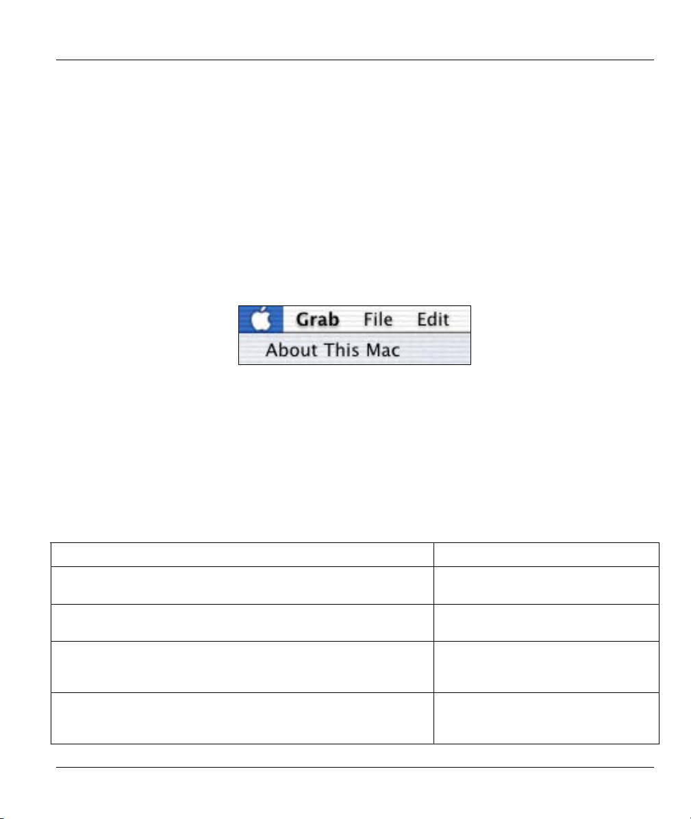
1.1 Operating Systems
The modem drivers are compatible with the Macintosh operating system versions 10.1.3 and later.
Click the Apple icon and then About This Mac in order to see which OS version is on your Macintosh.
Figure 1-1 About This Mac
The screens on your computer may differ slightly from the screens shown here depending on the version of
your operating system.
1.2 Internet Account Information
You should have an Internet account already set up and been given most of the following information.
Table 1-1 Internet Account Information
REQUIRED INFORMATION FILL IN THE BLANKS
Driver Type:
RFC 1483, PPPoE or PPPoA.
Mode (with RFC 1483)
Bridged IP or Routed IP.
VPI:
The Virtual Path Identifier number identifies a bundle of virtual
channels.
VCI:
The Virtual Channel Identifier number identifies a logical
connection between end stations.
Installing Your Modem 1-1
Page 14
Prestige 630 ADSL USB Modem
Table 1-1 Internet Account Information
REQUIRED INFORMATION FILL IN THE BLANKS
Encapsulation Type:
LLC or VC/MUX.
User Name:
For PPPoA or PPPoE, this lets your ISP know which account you
are logging into.
Password:
For PPPoA or PPPoE, this protects your account from
unauthorized use.
Your modem supports RFC 1483, PPPoA (Point to Point Protocol over ATM) and PPPoE (Point to Point
Protocol over Ethernet) drivers. These refer to the underlying data transport protocols. The RFC 1483 driver
works as an always-on account. The PPPoA and PPPoE drivers function as dial-up accounts.
When using the RFC 1483 driver, select the mode that your ISP uses, either Bridged IP or Routed IP.
The encapsulation type is also called multiplexing. Your modem supports both LLC and VC/MUX.
See the appendix for more information about VPI and VCI.
1.3 Installation
The following sections describe how to install your modem driver and modem. Install the modem driver
first and then the modem hardware.
Save and close all other running programs before installing the modem driver.
1.3.1 Modem Driver Installation
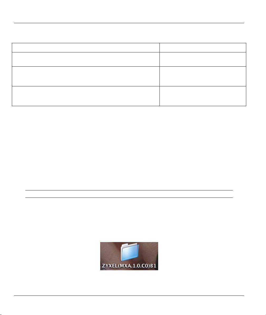
Step 1. Insert the included CD into the CD-ROM drive. An icon for the CD appears.
Step 2. Double-click the CD’s icon.
Step 3. Double-click the ZyXEL Mac X folder.
Figure 1-2 ZyXEL Mac X Folder
1-2 Installing Your Modem
Page 15
Prestige 630 ADSL USB Modem
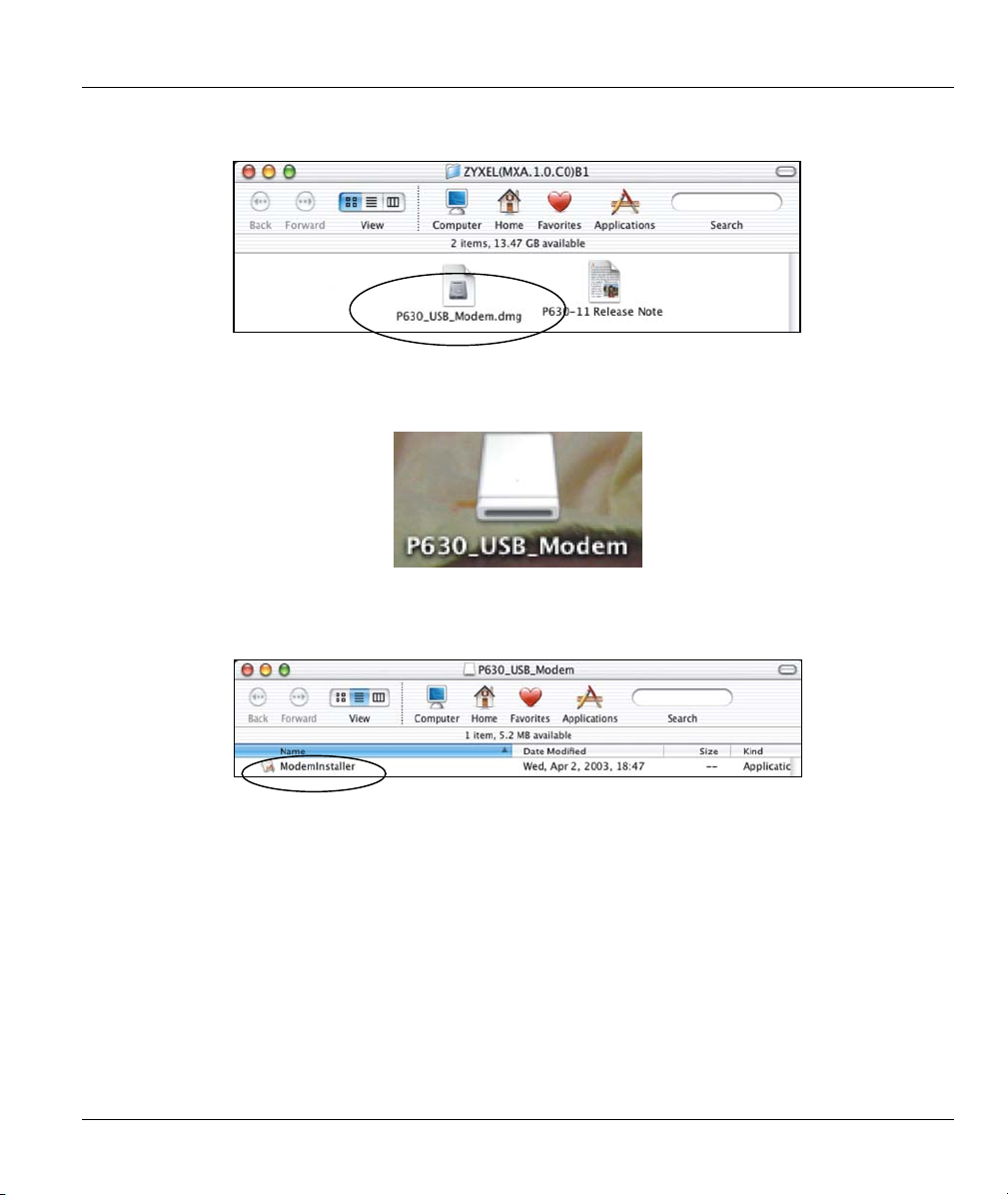
Step 4. In the resulting folder, double-click the .dmg file. This creates a virtual installer disc.
Figure 1-3 DMG File
Step 5. Double-click the virtual disc.
Figure 1-4 Virtual Disk
Step 6. Double-click the ModemInstaller file.
Figure 1-5 ModemInstaller
Installing Your Modem 1-3
Page 16

Prestige 630 ADSL USB Modem
Step 7. Click Install.
Figure 1-6 Select Install
Step 8. In the Welcome screen, click Continue.
Step 9. Enter the administrator username and password for your Macintosh. Click OK.
Figure 1-7 Authenticate
Step 10. Read the text in the Important Information screen and click Continue.
Step 11. Read the license agreement and click Continue.
Step 12. Click Agree.
Step 13. In the Select a Destination screen, select a destination (this must be on an actual physical hard
drive on the Macintosh, not a virtual drive) and click Continue.
1-4 Installing Your Modem
Page 17

Prestige 630 ADSL USB Modem
Figure 1-8 Select a Destination
Step 14. In the Easy Install screen, click Install; do not modify any settings.
Step 15. Click Continue Installation in the drop-down screen to proceed.
Step 16. Your ISP only uses one driver type for your DSL connection. It is important that you choose the
correct driver since you have to configure the Macintosh for a specific driver type in order to
make a DSL connection (see Chapter 2). Click Keep PPP to use the PPPoA driver. Click Keep
RFC 1483 to use the RFC 1483 driver or PPPoE and not install the PPPoA driver.
Click Keep RFC1483 if you need RFC 1483 or PPPoE.
Figure 1-9 Select Driver Type
Installing Your Modem 1-5
Page 18

Prestige 630 ADSL USB Modem
Step 17. Type the VPI and VCI that your ISP or telephone company gave you and click OK.
Figure 1-10 Set VPI and VCI
Step 18. Select LLC Encapsulation or VC/MUX Encapsulation according to the information from
your ISP (see Table 1-1). When you are installing the RFC 1483 driver, select Routed IP or
Bridged IP mode according to the information given to you by your ISP (see Table 1-1). For
PPPoE, select Bridged IP mode. You do not select either Routed IP or Bridged IP with the
PPPoA driver (they are grayed out). Click OK.
Figure 1-11 Select Mode and Encapsulation
Step 19. Make sure you have saved and closed all other running applications and click Restart to restart
your computer and complete the modem driver installation.
1-6 Installing Your Modem
Page 19
Prestige 630 ADSL USB Modem
1.3.2 Modem Hardware Installation
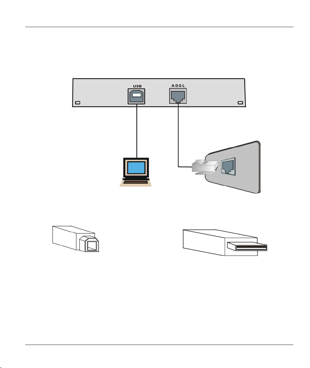
Step 1. Connect the square end of the USB cable to the back of your modem and then connect the
rectangular end of the USB cable to your computer’s USB port.
Figure 1-12 Back Panel Connections
Connect this cable end to your modem. Connect this cable end to your computer.
Figure 1-13 USB Cable Connectors
Step 2. Use a telephone wire to connect the ADSL port to a telephone wall jack.
Use a splitter (optional) in order to plug a phone into the same telephone line. See the following figure.
Installing Your Modem 1-7
Page 20

Prestige 630 ADSL USB Modem
Figure 1-14 Splitter
You may opt to buy a telephone microfilter to install between the wall jack and your telephone(s). A
microfilter acts as a low pass filter that screens out possible interference. See the following figure.
Figure 1-15 Microfilter
1.4 Front Panel LEDs
The LEDs on the front panel of your modem indicate operational status. The table after the following figure
describes the LED functions.
1-8 Installing Your Modem
Page 21

Figure 1-16 Front Panel LEDs
1.5 Front Panel LED Descriptions
Table 1-2 LED Descriptions
LED FUNCTION DESCRIPTION
USB
ADSL
USB Interface
and Modem
Power
Connection
ADSL Interface This LED is off when the software driver has not been installed or after you click
This LED is off when the modem’s USB port is not connected or not receiving
power.
The LED is on when the USB is connected, receiving power, and the driver
software is installed.
This LED blinks during data transfer or whenever the ADSL link is up.
the Disconnect button in the CSA interface.
This LED is on when the ADSL link is up.
This LED blinks when the ADSL link is connecting or waiting to connect.
Prestige 630 ADSL USB Modem
See Chapter 2 for instructions on how to configure your Macintosh and connect to the Internet.
Installing Your Modem 1-9
Page 22

Page 23

Prestige 630 ADSL USB Modem
Chapter 2
Configuring Your Macintosh for Internet
Access
This chapter describes how to configure your Macintosh computer for DSL Internet access using
the RFC1483, PPPoE or PPPoA driver.
2.1 Making a DSL Connection with RFC1483
Use the following steps to configure your Macintosh when using a RFC1483 driver.
Step 1. Click the Apple icon and System Preferences.
Figure 2-1 Open System Preferences
Step 2. Click Network.
Figure 2-2 System Preferences
Installing Your Modem 2-1
Page 24

Prestige 630 ADSL USB Modem
Step 3. A New Port Detected screen opens when the computer detects that the ADSL link is up. Click
OK.
Figure 2-3 New Port Detected
Step 4. In the Network screen, select Ethernet Adaptor (en x) in the Show field. In the TCP/IP tab,
select Using DHCP in the Configure field if you are using the bridged IP mode or Manually if
you are using the routed IP mode. Click Apply Now.
2-2 Installing Your Modem
Page 25

Prestige 630 ADSL USB Modem
Figure 2-4 Network: TCP/IP Tab
Step 5. Open your web browser.
2.2 Making a DSL Connection with PPPoE
Use the following steps to configure your Macintosh when using PPPoE. PPPoE is a dial-up connection, so
you configure the driver and create a dial-up connection to use. The dial-up connection is not necessary
with RFC 1483.
Step 1. Click the Apple icon and System Preferences and then Networking (see Figure 2-1 and Figure
2-2).
Step 2. A New Port Detected screen opens when the computer detects that the ADSL link is up. Click
OK (see Figure 2-3).
Installing Your Modem 2-3
Page 26

Prestige 630 ADSL USB Modem
Step 3. In the Network screen, select Ethernet Adaptor (en x) in the Show field. Click the PPPoE
tab and select the Connect using PPPoE check box. Type the information from your ISP in the
PPPoE Service Name, Account Name and Password fields. Select the Show PPPoE status in
menu bar check box. Click Apply Now.
Figure 2-5 Network: PPPoE Tab
2-4 Installing Your Modem
Page 27

Prestige 630 ADSL USB Modem
Step 4. Click the menu bar icon and select Connect.
Figure 2-6 PPPoE Icon Connect
2.3 Making a DSL Connection with PPPoA
Use the following steps to configure your Macintosh when using a PPPoA driver. PPPoA is a dial-up
connection, so you configure the driver and create a dial-up connection to use. The dial-up connection is not
necessary with RFC 1483.
Step 1. Click the Apple icon and System Preferences and then Networking (see Figure 2-1 and Figure
2-2).
Step 2. A New Port Detected screen opens when the computer detects that the ADSL link is up. Click
OK.
Figure 2-7 New Port Detected
Step 3. In the Network screen, select adslmodem.
Installing Your Modem 2-5
Page 28

Prestige 630 ADSL USB Modem
Figure 2-8 Network
2-6 Installing Your Modem
Page 29

Prestige 630 ADSL USB Modem
Step 4. Click the Modem tab. Select Null Modem 115200 in the Modem field. Select the Show
modem status in menu bar check box.
Figure 2-9 Network: Modem Tab
Installing Your Modem 2-7
Page 30

Prestige 630 ADSL USB Modem
Step 5. Click the PPP tab. Type your PPPoA account information from your ISP in the Account Name
and Password fields. This creates your PPPoA dial-up account.
Figure 2-10 Network: PPP Tab
2-8 Installing Your Modem
Page 31

Prestige 630 ADSL USB Modem
Step 6. Click the TCP/IP tab (see Figure 2-8). Make sure that the Configure field is set to Using PPP
and click Apply Now.
Step 7. Click the menu bar icon and select Connect.
Figure 2-11 PPPoA Connect Icon
Click the Internet Connect icon at the bottom of the
desktop.
Figure 2-12 Internet Connect Icon
Installing Your Modem 2-9
Page 32

Prestige 630 ADSL USB Modem
Step 8. Enter your password and click Connect.
Figure 2-13 PPPoA Connect Screen
2-10 Installing Your Modem
Page 33

Prestige 630 ADSL USB Modem
Chapter 3
Control And Status
This chapter introduces the Control and Status Application GUI.
3.1 CSA
The CSA (Control and Status Application) displays information about your modem’s status and
performance, and also allows you to connect or disconnect an ADSL connection.
3.2 CSA Icon
The CSA icon displays information about your modem’s connection status and allows you to open the CSA
interface. Do the following to display the CSA icon in the menu bar at the top of the screen.
3.2.1 Procedure to Display the CSA Icon
Step 1. Click the Macintosh HD icon.
Figure 3-1 Macintosh HD Icon
Control and Status 3-1
Page 34

Prestige 630 ADSL USB Modem
Step 2. Double-click Applications.
Figure 3-2 Macintosh HD Applications
Step 3. Double-click AME Control and Status.
Figure 3-3 Control and Status Icon
Step 4. The CSA icon displays in the menu bar at the top of the screen.
CSA Icon
Figure 3-4 CSA Icon
3.2.2 Icon Colors
The color of the icon indicates the connection state of the modem as follows:
• Black indicates that the modem is unavailable.
• Red indicates that the modem is not connected.
• Blue indicates that the modem is waiting to initialize a connection.
3-2 Control and Status
Page 35
Prestige 630 ADSL USB Modem
• Yellow indicates that the modem is initializing a connection.
• Green indicates that the connection is up and the modem is functioning.
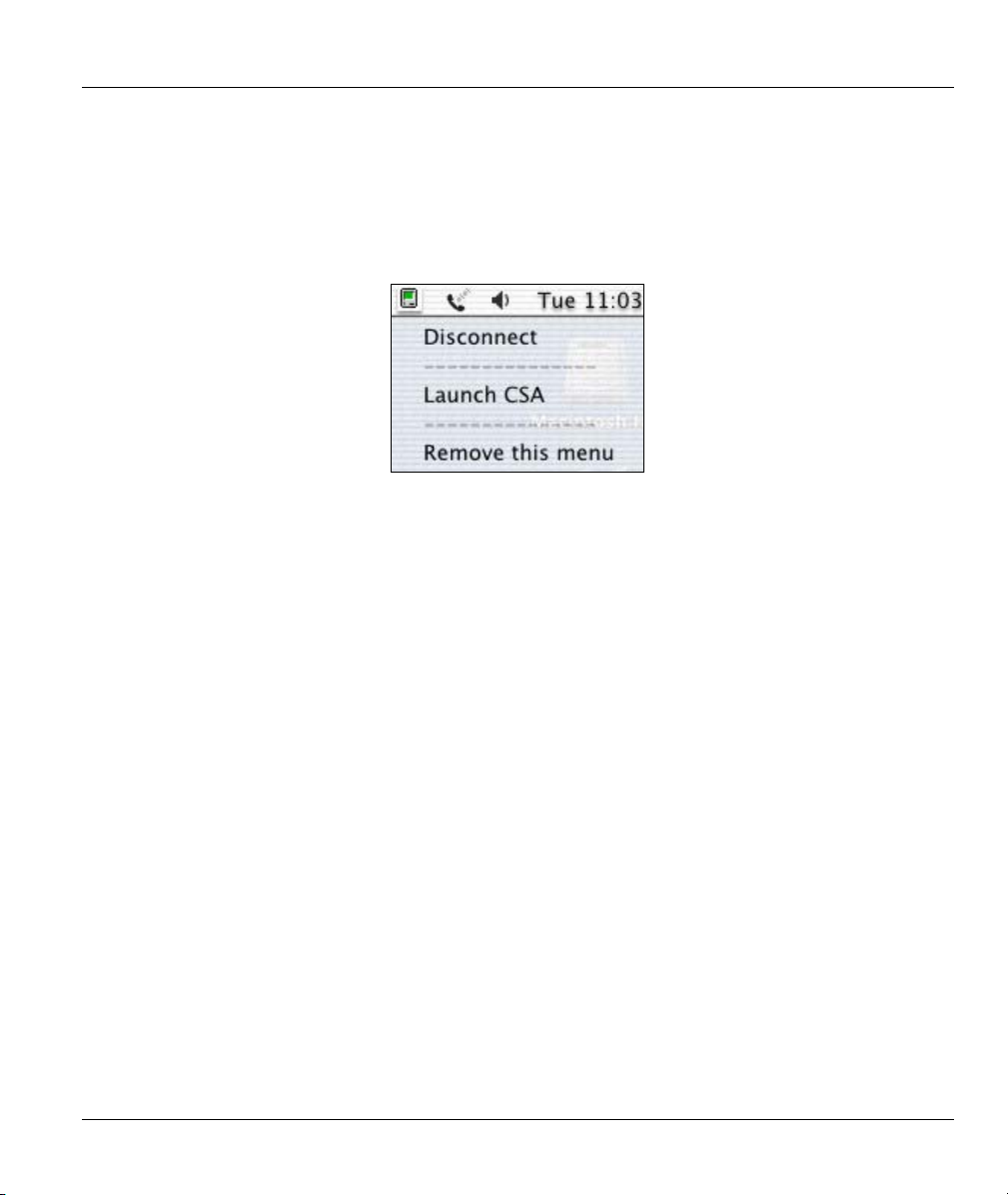
3.3 ADSL Control and Status Interface Screen
Click the CSA icon on the menu bar at the top of the screen and then Launch CSA.
Figure 3-5 Launch CSA
Control and Status 3-3
Page 36

Prestige 630 ADSL USB Modem
Figure 3-6 Control and Status Application
3.3.1 Modem Performance
Two bar graphs indicate the throughput rates. One indicates the transmit rate (upstream) of data being sent
out from the modem and the second indicates the receive rate (downstream).
3.3.2 Connection Status
This field displays ADSL link connected when there is an ADSL connection. It displays ADSL link
disconnected when there is not an ADSL connection.
3-4 Control and Status
Page 37

Prestige 630 ADSL USB Modem
3.3.3 Device Status
This field displays ADSL modem available when the modem is properly connected to the computer and
the modem driver is installed. The field displays ADSL modem not available when the modem is not
connected to the computer or the modem driver is not properly installed.
3.3.4 Display Modem Status in Status Bar
Select this check box to have the CSA icon display in the menu bar at the top of the screen.
3.3.5 Connect
The connect/disconnect functions are controlled by the Connect/Disconnect button. The button is disabled
when the modem is unavailable. This happens when the modem driver fails to communicate properly or is
disabled.
The status of the modem determines the button text. Connect is displayed when the modem is not
connected and not cycling in order to connect. Disconnect is displayed when the modem is connected.
3.3.6 Close
The Close button closes only the CSA interface screen and does not have any affect on the ADSL
connection.
Control and Status 3-5
Page 38

Page 39

Prestige 630 ADSL USB Modem
Chapter 4
Uninstalling Your Modem
This chapter tells how to uninstall your modem hardware and software.
4.1 Uninstalling the Hardware
Disconnect the USB cable from your Macintosh’s USB port.
4.2 Uninstalling the Driver
Use the following steps to remove your modem’s software driver.
Save and close all other running programs before installing the modem driver.
Step 1. Insert the included CD into the CD-ROM drive. An icon for the CD appears.
Step 2. Double-click the CD’s icon.
Step 3. Double-click the ZyXEL Mac X folder.
Figure 4-1 ZyXEL Mac X Folder
Uninstalling Your Modem 4-1
Page 40

Prestige 630 ADSL USB Modem
Step 4. In the resulting folder, double-click the .dmg file. This creates a virtual installer disc.
Figure 4-2 DMG File
Step 6. Double-click the virtual disc.
Figure 4-3 Virtual Disk
Step 7. Double-click the ModemInstaller file.
Figure 4-4 ModemInstaller
Step 8. Click Uninstall.
4-2 Uninstalling Your Modem
Page 41

Prestige 630 ADSL USB Modem
Figure 4-5 Select Uninstall
Step 9. Make sure you have saved and closed all other running applications and click OK in the screen
that notifies you that status bar applications will be stopped.
Uninstalling Your Modem 4-3
Page 42

Prestige 630 ADSL USB Modem
Step 10. Enter the administrator username and password for your Macintosh. Click OK.
Figure 4-6 Authenticate
Step 11. In the Uninstall complete screen, click OK to restart your computer and complete the
uninstallation.
Figure 4-7 Uninstall Complete
4-4 Uninstalling Your Modem
Page 43

Prestige 630 ADSL USB Modem
Chapter 5
Troubleshooting
This chapter covers potential problems and the possible solutions.
Table 5-1 Troubleshooting
PROBLEM CORRECTIVE ACTION
None of the LEDs turn on when
I start the modem.
I cannot access the modem via
my computer.
I cannot connect to the Internet. Make sure the ADSL port is properly connected to the telephone wall
Make sure your computer is turned on.
Check the USB cable connections between the modem and your
computer.
Make sure you can open the CSA interface (refer to Chapter 3 for
details. Install the software driver if the CSA is not present.
Carefully follow the instructions in this User’s Guide to uninstall and
reinstall the software driver.
Make sure the modem’s USB port is connected to your computer’s
USB port.
Restart your computer.
jack.
Use the Connect/Disconnect button in the ADSL Control and
Status screen to reinitiate the ADSL connection.
With PPPoE, see section 2.2 and make sure that you have
configured the correct user name and password.
With PPPoA, see section 2.3 and make sure that you have
configured the correct user name and password.
Restart your computer.
Troubleshooting 5-1
Page 44

Page 45

Prestige 630 ADSL USB Modem
Appendix A
VPI and VCI
ATM is a connection-oriented technology, meaning that it sets up virtual circuits over which end systems
communicate. The terminology for virtual circuits is as follows:
Virtual Channel Logical connections between ATM switches
Virtual Path A bundle of virtual channels
Virtual Circuit A series of virtual paths between end points in a network
Diagram 1 Virtual Circuit Topology
Think of a virtual path as a cable that contains a bundle of wires. The cable connects two points and wires
within the cable provide individual circuits between the two points. In an ATM cell header, a VPI (Virtual
Path Identifier) identifies a link formed by a virtual path; a VCI (Virtual Channel Identifier) identifies a
channel within a virtual path.
The VPI and VCI identify a virtual path, that is, termination points between ATM switches. A series of
virtual paths make up a virtual circuit.
VPI and VCI A
Page 46

Page 47

Prestige 630 ADSL USB Modem
Index
C
Close Button..................................................... 3-5
Compatibility and Compliance .......................... xi
Configuration ................................................... 2-1
Connect Button ................................................3-5
Connection Status ............................................3-4
Connections...................................................... 1-8
Contacting Customer Support............................ vi
Control and Status Application ........................ 3-1
Copyright ............................................................ ii
Disclaimer....................................................... ii
Trademarks ..................................................... ii
CSA.................................................................. 3-1
Customer Support .............................................. vi
D
Device Status ................................................... 3-5
Downstream Data Rates..................................... xi
H
Hardware Installation....................................... 1-7
I
Information for Canadian Users..........................iv
Caution............................................................iv
Note ................................................................iv
L
LEDs................................................................ 1-8
Limited Warranty............................................... iii
M
Macintosh Configuration ................................. 2-1
Microfilter........................................................ 1-8
Modem Performance ....................................... 3-4
N
Needed Information......................................... 1-1
O
Online Registration............................................ iii
Driver Installation ............................................ 1-2
F
FCC..................................................................... v
FCC Rules........................................................... v
Features.............................................................. xi
Federal Communications Commission (FCC)
Interference Statement .................................... v
Index C
Operating Systems........................................... 1-1
P
Power Supply......................................................xi
PPPoA.............................................................. 2-5
R
Related Documentation.......................................xi
Removing......................................................... 4-1
Page 48

Prestige 630 ADSL USB Modem
Repair................................................................. iii
RFC 1483......................................................... 1-2
RFC1483.......................................................... 2-1
RJ-11...................................................................xi
S
Service ............................................................... iii
Support Disk.......................................................xi
Syntax Conventions............................................xi
T
Table of Contents...............................................vii
Troubleshooting............................................... 5-1
U
Uninstalling ..................................................... 4-1
Upstream Data Rates ..........................................xi
USB as Power Source.........................................xi
USB Compliance................................................ xi
User Interface Screens......................................3-1
V
Virtual Channel ..................................................A
Virtual Circuit..................................................... A
Virtual Path......................................................... A
W
Warranty.............................................................iii
Z
ZyXEL Contact Information ..............................vi
ZyXEL Limited Warranty
Note ................................................................iii
ZyXEL Web Site ................................................ xi
D Index
 Loading...