

Page 1

Prestige 100L
IDSL Router
User’s Guide
Version 2.40
June, 2000
Page 2

Prestige 100L IDSL Router
Prestige 100L
IDSL Router
COPYRIGHT
Copyright © 2000 by ZyXEL Communications Corporation.
The contents of this publication may not be reproduced in any part or as a whole, transcribed, stored in a retrieval
system, translated into any language, or transmitted in any form or by any means, electronic, mechanical, magnetic,
optical, chemical, photocopying, manual, or otherwise, without the prior written permission of ZyXEL
Communications Corporation.
Published by ZyXEL Communications Corporation. All rights reserved.
DISCLAIMER
ZyXEL does not assume any liability arising out of the application or use of any products, or software described herein.
Neither does it convey any license under its patent rights nor the patent rights of others. ZyXEL further reserves the
right to make changes in any products described herein without notice. This publication is subject to change without
notice.
TRADEMARKS
Trademarks mentioned in this publication are used for identification purposes only and may be properties of their
respective owners.
ii
Page 3

Prestige 100L IDSL Router
Federal Communications Commission (FCC) Interference Statement
This device complies with Part 15 of FCC rules. Operation is subject to the following two conditions:
l This device may not cause harmful interference.
l This device must accept any interference received, including interference that may cause undesired operations.
This equipment has been tested and found to comply with the limits for a Class B digital device pursuant to Part 15 of
the FCC Rules. These limits are designed to provide reasonable protection against harmful interference in a commercial
environment. This equipment generates, uses, and can radiate radio frequency energy, and if not installed and used in
accordance with the instructions, may cause harmful interference to radio communications.
If this equipment does cause harmful interference to radio/television reception, which can be determined by turning the
equipment off and on, the user is encouraged to try to correct the interference by one or more of the following
measures:
1. Reorient or relocate the receiving antenna.
2. Increase the separation between the equipment and the receiver.
3. Connect the equipment into an outlet on a circuit different from that to which the receiver is connected.
4. Consult the dealer or an experienced radio/TV technician for help.
NOTICE 1
Changes or modifications not expressly approved by the party responsible for compliance could void the user's
authority to operate the equipment.
NOTICE 2
Shielded RS-232C cables are required to be used to ensure compliance with FCC Part 15, and it is the responsibility of
the user to provide and use shielded RS-232C cables.
iii
Page 4
Prestige 100L IDSL Router
iv
Page 5

Prestige 100L IDSL Router
Information for Canadian Users
The Industry Canada label identifies certified equipment. This certification means that the equipment meets certain
telecommunications network protective, operation, and safety requirements. The Industry Canada does not guarantee
that the equipment will operate to a user's satisfaction.
Before installing this equipment, users should ensure that it is permissible to be connected to the facilities of the local
telecommunications company. The equipment must also be installed using an acceptable method of connection. In some
cases, the company's inside wiring associated with a single line individual service may be extended by means of a
certified connector assembly. The customer should be aware that the compliance with the above conditions may not
prevent degradation of service in some situations.
Repairs to certified equipment should be made by an authorized Canadian maintenance facility designated by the
supplier. Any repairs or alterations made by the user to this equipment, or equipment malfunctions, may give the
telecommunications company cause to request the user to disconnect the equipment.
For their own protection, users should ensure that the electrical ground connections of the power utility, telephone lines,
and internal metallic water pipe system, if present, are connected together. This precaution may be particularly
important in rural areas.
CAUTION
Users should not attempt to make such connections themselves, but should contact the appropriate electrical inspection
authority, or electrician, as appropriate.
NOTE
This digital apparatus does not exceed the Class A limits for radio noise emissions from digital apparatus set out in the
radio interference regulations of Industry Canada.
v
Page 6
Prestige 100L IDSL Router
vi
Page 7

Prestige 100L IDSL Router
Declaration of Conformity
We, the Manufacturer/Importer,
ZyXEL Communications Corp.
No. 6, Innovation Road II,
Science-Based Industrial Park,
Hsinchu, Taiwan, 300 R.O.C
declare that the product
Prestige 100L
(reference to the specification under which conformity is declared)
is in conformity with
STANDARD
• EN 50082-1
• EN 55022
• EN 61000-3-2
• EN 61000-3-3
• EN 61000-4-2
• EN 61000-4-3
• EN 61000-4-4
• EN 61000-4-5
• EN 61000-4-6
• EN 61000-4-8
• EN 61000-4-11
• ENV 50204
NOTE: The TCF file can be obtained at: ZyXEL Communications Services, GmbH.
Generic immunity standard 1997
Radio disturbance characteristics – Limits and method of
measurement.
Disturbance in supply system caused by household appliances
and similar electrical equipment “Harmonics”.
Disturbance in supply system caused by household appliances
and similar electrical equipment “Voltage fluctuations”.
Electrostatic discharge immunity test – Basic EMC Publication 1995
Radiated, radio-frequency, electromagnetic field immunity test 1995
Electrical fast transient / burst immunity test - Basic EMC
Publication
Surge immunity test 1995
Immunity to conducted disturbances, induced by radio-frequency
fields
Power magnetic test 1993
Voltage dips, short interruptions and voltage variations immunity
tests
Electromagnetic field from digital telephones test 1995
Thaliastrasse 125a/2/2/4
A-1160 Vienna, AUSTRIA.
STANDARD ITEM
VERSION
1994
1995
1995
1995
1995
1994
vii
Page 8

Prestige 100L IDSL Router
ZyXEL Limited Warranty
ZyXEL warrants to the original end user (purchaser) that this product is free from any defects in materials or
workmanship for a period of up to two years from the date of purchase. During the warranty period, and upon proof of
purchase, should the product have indications of failure due to faulty workmanship and/or materials, ZyXEL will, at its
discretion, repair or replace the defective products or components without charge for either parts or labor, and to
whatever extent it shall deem necessary to restore the product or components to proper operating condition. Any
replacement will consist of a new or re-manufactured functionally equivalent product of equal value, and will be solely
at the discretion of ZyXEL. This warranty shall not apply if the product is modified, misused, tampered with, damaged
by an act of God, or subjected to abnormal working conditions.
NOTE
Repair or replacement, as provided under this warranty, is the exclusive remedy of the purchaser. This warranty is in
lieu of all other warranties, express or implied, including any implied warranty of merchantability or fitness for a
particular use or purpose. ZyXEL shall in no event be held liable for indirect or consequential damages of any kind of
character to the purchaser.
To obtain the services of this warranty, contact ZyXEL's Service Center; refer to the separate Warranty Card for your
Return Material Authorization number (RMA). Products must be returned Postage Prepaid. It is recommended that the
unit be insured when shipped. Any returned products without proof of purchase or those with an out-dated warranty will
be repaired or replaced (at the discretion of ZyXEL) and the customer will be billed for parts and labor. All repaired or
replaced products will be shipped by ZyXEL to the corresponding return address, Postage Paid (USA and territories
only). If the customer desires some other return destination beyond the U.S. borders, the customer shall bear the cost of
the return shipment. This warranty gives you specific legal rights, and you may also have other rights that vary from
state to state.
Online Registration
Do not forget to register your Prestige (fast, easy online registration at www.zyxel.com for free future product updates
and information.
viii
Page 9
Prestige 100L IDSL Router
Customer Support
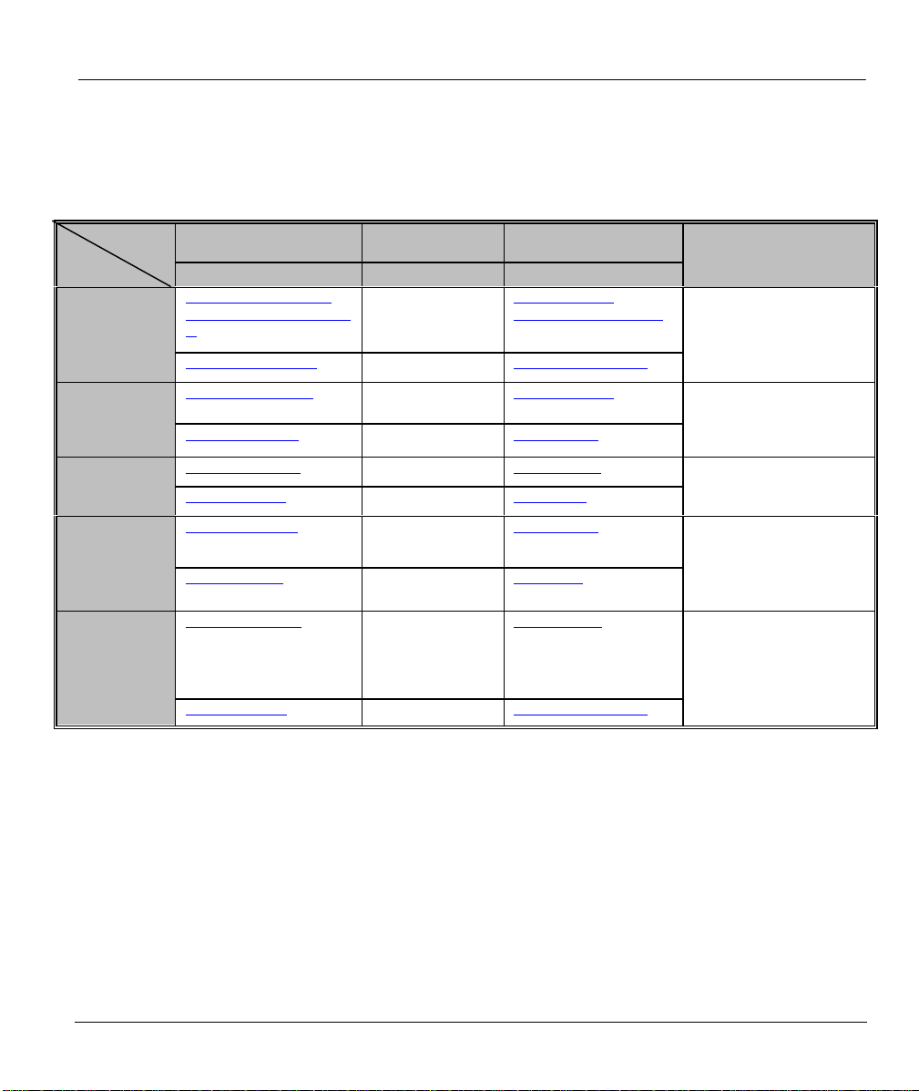
If you have questions about your ZyXEL product or desire assistance, contact ZyXEL Communications
Corporation offices worldwide, in one of the following ways:
METHOD
REGION
WORLDWIDE
NORTH
AMERICA
SCANDINAVIA
AUSTRIA
GERMANY
EMAIL – SUPPORT TELEPHONE WEB SITE
EMAIL – SALES FAX FTP SITE
support@zyxel.com.tw
support@europe.zyxel.co
+886-3-578-3942 www.zyxel.com
www.europe.zyxel.com
m
sales@zyxel.com.tw +886-3-578-2439 ftp.europe.zyxel.com
support@zyxel.com +1-714-632-0882
www.zyxel.com
800-255-4101
sales@zyxel.com +1-714-632-0858 ftp.zyxel.com
support@zyxel.dk +45-3955-0700 www.zyxel.dk
sales@zyxel.dk +45-3955-0707 ftp.zyxel.dk
support@zyxel.at +43-1-4948677-0
www.zyxel.at
0810-1-ZyXEL
0810-1-99935
sales@zyxel.at
support@zyxel.de
+43-1-4948678
+49-2405-6909-0
0180-5213247
Tech Support hotline
0180-5099935
RMA/Repair hotline
ftp.zyxel.at
Note: for Austrian users with *.at
domain only!
www.zyxel.de
sales@zyxel.de +49-2405-6909-99 ftp.europe.zyxel.com
REGULAR MAIL
ZyXEL Communications
Corp., 6 Innovation Road II,
Science-Based Industrial
Park, HsinChu, Taiwan.
ZyXEL Communications Inc.,
1650 Miraloma Avenue,
Placentia, CA 92870, U.S.A.
ZyXEL Communications A/S,
Columbusvej 5, 2860
Soeborg, Denmark.
ZyXEL Communications
Services GmbH.,
Thaliastrasse 125a/2/2/4,
A-1160 Vienna, Austria
ZyXEL Deutschland GmbH.,
Adenauerstr. 20/A4, D-52146
Wuerselen, Germany.
ix
Page 10

Page 11

Prestige 100L IDSL Router
Table of Contents
Declaration of Conformity...................................................................................................... vii
Cutomer Support..................................................................................................................... ix
Table of Contents..................................................................................................................... xi
List of Figures......................................................................................................................... xv
List of Tables......................................................................................................................... xvii
Preface ................................................................................................................................... xix
Chapter 1 : Getting to Know Your Prestige............................................................................ 1-1
1.1 The Prestige 100L IDSL Router ................................................................................. 1-1
1.2 Features of the Prestige 100L.................................................................................... 1-1
Chapter 2 : Hardware Installation and Initial Setup............................................................... 2-1
2.1 Front Panel LEDs and Back Panel Ports.................................................................... 2-1
2.1.1 Front Panel LEDs............................................................................................................... 2-1
2.2 Prestige 100L Rear Panel and Connections............................................................... 2-2
2.3 Housing..................................................................................................................... 2-3
2.4 Power Up Your Prestige............................................................................................. 2-4
2.5 Navigating the SMT (System Management Terminal) Interface................................... 2-4
2.5.1 Main Menu.........................................................................................................................2-5
2.5.2 System Management Terminal Interface Summary..............................................................2-6
2.6 Changing the System Password................................................................................. 2-7
2.6.1 Resetting the Prestige ......................................................................................................... 2-7
2.7 General Setup ........................................................................................................... 2-8
2.8 IDSL Setup................................................................................................................ 2-9
2.9 Ethernet Setup........................................................................................................... 2-9
2.9.1 General Setup................................................................................................................... 2-10
Chapter 3 : Internet Access.................................................................................................... 3-1
Table of Contents xi
Page 12

Prestige 100L IDSL Router
3.1 TCP/IP and DHCP for LAN........................................................................................ 3-1
3.1.1 Factory LAN Defaults.........................................................................................................3-1
3.1.2 IP Address and Subnet Mask ...............................................................................................3-1
3.1.3 Private IP Addresses ...........................................................................................................3-2
3.1.4 RIP (Routing Information Protocol) Setup........................................................................... 3-2
3.1.5 DHCP (Dynamic Host Configuration Protocol) Configuration .............................................3-3
3.2 TCP/IP and DHCP Ethernet Setup............................................................................. 3-4
3.3 Internet Access Setup................................................................................................ 3-6
3.4 Single User Account (SUA)........................................................................................ 3-7
3.4.1 Advantages of SUA ............................................................................................................ 3-7
3.4.2 Single User Account Configuration .....................................................................................3-8
3.5 Multiple Servers Behind the SUA............................................................................... 3-8
3.5.1 Configuring a Server Behind the SUA.................................................................................3-9
Chapter 4 : Remote Node Setup............................................................................................. 4-1
4.1 Remote Node Profile ................................................................................................. 4-1
4.1.1 Editing PPP Options ...........................................................................................................4-3
4.2 Editing TCP/IP Options.............................................................................................. 4-3
4.3 Remote Node Filter.................................................................................................... 4-7
Chapter 5 : IP Static Route Setup .......................................................................................... 5-1
5.1 IP Static Route Setup................................................................................................. 5-2
Chapter 6 : Filter Configuration ............................................................................................. 6-1
6.1 About Filtering ........................................................................................................... 6-1
6.1.1 The Filter Structure of the Prestige......................................................................................6-2
6.2 Configuring a Filter Set .............................................................................................. 6-4
6.2.1 Filter Rules Summary Menu................................................................................................6-6
6.2.2 Configuring a Filter Rule ....................................................................................................6-7
6.2.3 TCP/IP Filter Rule.............................................................................................................. 6-7
6.2.4 Generic Filter Rule............................................................................................................6-11
xii Table of Contents
Page 13

Prestige 100L IDSL Router
6.3 Example Filter.......................................................................................................... 6-13
6.4 Applying a Filter and Factory Defaults...................................................................... 6-16
6.4.1 Ethernet Traffic ................................................................................................................ 6-16
6.4.2 Remote Node Filters ......................................................................................................... 6-16
Chapter 7 : SNMP (Simple Network Management Protocol)................................................. 7-1
Chapter 8 : System Security................................................................................................... 8-1
Chapter 9 : Telnet Configuration and Capabilities ................................................................ 9-1
9.1 About Telnet Configuration......................................................................................... 9-1
9.2 Telnet Capabilities...................................................................................................... 9-1
9.2.1 Single Administrator........................................................................................................... 9-1
9.2.2 System Timeout..................................................................................................................9-1
Chapter 10 : System Information and Diagnosis ................................................................. 10-1
10.1 System Status ......................................................................................................... 10-2
10.2 System Information and Console Port Speed........................................................... 10-4
10.2.1 System Information .......................................................................................................... 10-4
10.2.2 Console Port Speed........................................................................................................... 10-5
10.3 Log and Trace.......................................................................................................... 10-6
10.3.1 Viewing Error Log............................................................................................................ 10-6
10.3.2 Syslog Server ................................................................................................................... 10-7
10.4 Diagnostic................................................................................................................ 10-8
Chapter 11 : Transferring Files..............................................................................................11-1
11.1 Filename Conventions .............................................................................................. 11-1
11.2 Backup Configuration................................................................................................11-2
11.3 Restore Configuration............................................................................................... 11-2
11.4 Upload Firmware ......................................................................................................11-3
11.4.1 Uploading the Router Firmware ........................................................................................ 11-3
11.4.2 Uploading Router Configuration File................................................................................ 11-4
11.5 TFTP File Transfer....................................................................................................11-5
Table of Contents xiii
Page 14

Prestige 100L IDSL Router
11.5.1 Using the FTP command from the DOS Prompt ................................................................11-6
11.6 Command Interpreter Mode......................................................................................11-8
Chapter 12 : Troubleshooting............................................................................................... 12-1
12.1 Problems Starting Up the Prestige ........................................................................... 12-1
12.2 Problems with the LAN Interface.............................................................................. 12-2
12.3 Problems with the WAN interface............................................................................. 12-2
Glossary....................................................................................................................................A
Appendix A Important Safety Instructions........................................................................... M
Appendix B Power Adapter Specifications ...........................................................................N
Index..........................................................................................................................................O
xiv Table of Contents
Page 15

Prestige 100L IDSL Router
List of Figures
Figure 2-1 Front Panel........................................................................................................................2-1
Figure 2-2 Prestige 100L Rear Panel and Connections ........................................................................2-2
Figure 2-3 Initial Screen .....................................................................................................................2-4
Figure 2-4 Password Screen................................................................................................................2-4
Figure 2-5 Prestige 100L Main Menu .................................................................................................2-6
Figure 2-6 Menu 23 – System Security ...............................................................................................2-7
Figure 2-7 Menu 1 – General Setup ....................................................................................................2-8
Figure 2-8 Menu 2 – IDSL Setup........................................................................................................2-9
Figure 2-9 Menu 3 – Ethernet Setup .................................................................................................2-10
Figure 2-10 Menu 3.1 – General Ethernet Setup..................................................................................2-10
Figure 3-1 Menu 3 – Ethernet Setup Screen ........................................................................................3-4
Figure 3-2 Menu 3.2 – TCP/IP and DHCP Ethernet Setup Screen ........................................................ 3-4
Figure 3-3 Menu 4 – Internet Access Setup.........................................................................................3-6
Figure 3-4 Example of a SUA Topology.............................................................................................3-9
Figure 3-5 Multiple Server Configuration .........................................................................................3-10
Figure 4-1 Menu 11.1 – Remote Node Profile.....................................................................................4-1
Figure 4-2 Menu 11.2 – Remote Node PPP Options............................................................................4-3
Figure 4-3 Remote Node Filter ...........................................................................................................4-7
Figure 5-1 Example of an IP Static Route Setup..................................................................................5-1
Figure 5-2 Menu 12 – IP Static Route Setup........................................................................................5-2
Figure 5-3 Menu 12. 1 – Edit IP Static Route......................................................................................5-2
Figure 6-1 Outgoing Packet Filtering Process......................................................................................6-1
Figure 6-2 Filter Rule Process.............................................................................................................6-3
Figure 6-3 Menu 21.1.1 – TCP/IP Filter Rule......................................................................................6-8
Figure 6-4 Executing an IP Filter......................................................................................................6-10
List of Figures xv
Page 16

Prestige 100L IDSL Router
Figure 6-5 Menu 21.4.1.1 – Generic Filter Rule.................................................................................6-11
Figure 6-6 Telnet Filter Example.......................................................................................................6-13
Figure 6-7 Example Filter – Menu 21.1.1.......................................................................................... 6-14
Figure 6-8 Example Filter Rules Summary – Menu 21.1.3 .................................................................6-15
Figure 7-1 Menu 22 – SNMP Configuration........................................................................................7-1
Figure 8-1 Menu 23 – System Password ..............................................................................................8-1
Figure 9-1 Telnet Configuration on a TCP/IP Network ........................................................................9-1
Figure 10-1 Menu 24 – System Maintenance.......................................................................................10-1
Figure 10-2 Menu 24.1 – System Maintenance – Status.......................................................................10-2
Figure 10-3 Menu 24.2 – System Information and Console Port Speed ................................................ 10-4
Figure 10-4 Menu 24.2.1 – System Maintenance – Information ........................................................... 10-4
Figure 10-5 Menu 24.2.2 – System Maintenance – Change Console Port Speed.................................. 10-5
Figure 10-6 Menu 24.3 – System Maintenance – Log and Trace ..........................................................10-6
Figure 10-7 Examples of Error and Information Messages ...................................................................10-6
Figure 10-8 Menu 24.3.2 – System Maintenance – Syslog and Accounting..........................................10-7
Figure 10-9 Menu 24.4 – System Maintenance – Diagnostic................................................................ 10-8
Figure 11-1 Menu 24.5 – System Maintenance – Backup Configuration .............................................. 11-2
Figure 11-2 Menu 24.6 – System Maintenance – Restore Configuration ..............................................11-2
Figure 11-3 Menu 24.7 – System Maintenance – Upload Firmware..................................................... 11-3
Figure 11-4 Menu 24.7.1 – System Maintenance – Upload Router Firmware.......................................11-4
Figure 11-5 Menu 24.7.2 – System Maintenance – Upload Router Configuration File ..........................11-5
Figure 11-6 FTP Session Example ......................................................................................................11-6
Figure 11-7 Command Mode ..............................................................................................................11-8
xvi List of Figures
Page 17

Prestige 100L IDSL Router
List of Tables
Table 2-1 LED Functions...................................................................................................................2-1
Table 2-2 Main Menu Commands ...................................................................................................... 2-5
Table 2-3 Main Menu Summary......................................................................................................... 2-6
Table 2-4 General Setup Menu Field ..................................................................................................2-8
Table 2-5 IDSL Setup Menu Fields .................................................................................................... 2-9
Table 3-1 LAN DHCP Setup Menu Fields..........................................................................................3-5
Table 3-2 LAN TCP/IP Setup Menu Fields.........................................................................................3-6
Table 3-3 Internet Access Setup Menu Fields ..................................................................................... 3-7
Table 3-4 Single User Account Menu Fields....................................................................................... 3-8
Table 3-5 Services as Compared to Port Number .............................................................................. 3-10
Table 4-1 Fields in Menu 11.1............................................................................................................ 4-2
Table 4-2 Fields in Menu 11.2 (PPP Options ) .................................................................................... 4-3
Table 4-3 Protocol-dependent Parameters for Remote Node Setup ......................................................4-4
Table 4-4 Remote Node Network Layer Options Menu Fields............................................................. 4-5
Table 5-1 IP Static Route Menu Fields................................................................................................ 5-3
Table 6-1 Abbreviations Used in the Filter Rules Summary Menu.......................................................6-6
Table 6-2 Abbreviations Used If Filter Type Is IP ............................................................................... 6-7
Table 6-3 Abbreviations Used If Filter Type Is GEN ........................................................................... 6-7
Table 6-4 TCP/IP Filter Rule Menu Fields.......................................................................................... 6-8
Table 6-5 Generic Filter Rule Menu Fields ....................................................................................... 6-12
Table 7-1 Fields in Menu 22 (SNMP Configuration)........................................................................... 7-2
Table 10-1 System Maintenance – Status Menu Fields.................................................................... 10-3
Table 10-2 Fields in System Maintenance....................................................................................... 10-5
Table 10-3 System Maintenance Menu Syslog Parameters.............................................................. 10-7
Table 10-4 System Maintenance Menu Diagnostic .......................................................................... 10-8
List of Tables xvii
Page 18

Prestige 100L IDSL Router
Table 11-1 Filename Conventions ................................................................................................... 11-1
Table 11-2 Third Party TFTP Clients..............................................................................................11-7
Table 11-3 Third Party TFTP Clients – General Fields ..................................................................... 11-7
Table 12-1 Troubleshooting Starting Up Your Prestige....................................................................12-1
Table 12-2 Troubleshooting the LAN Interface................................................................................12-2
Table 12-3 Troubleshooting the WAN interface...............................................................................12-2
xviii List of Tables
Page 19

Prestige 100L IDSL Router
Preface
About Your Router
Congratulations on your purchase of the Prestige 100L IDSL Router. Do not forget to register your Prestige
(fast, easy online registration at www.zyxel.com) for free future product updates and information.
The Prestige 100L is the perfect companion to the Prestige 1600, offering inexpensive yet complete
telecommunications and internetworking solutions for your home or branch office. The Prestige is ideal for
everything from Internet access, to making LAN-to-LAN connections, to Remote Nodes. Distinguishing
features include:
q Support for a full range of networking protocols such as TCP/IP (Transmission Control Protocol/Internet
Protocol),
q Simple Network Management,
q Solid security features that give it the flexibility to provide a complete networking solution for Internet
access and business users.
Ease of Installation
The Prestige is a self-contained unit that is quick and easy to install.
Additional Installation Requirements
Your Prestige 100L is easy to install and to configure. In addition, there are other hardware and software
requirements you need before you can install and use your Prestige. These requirements include:
q IDSL service provided by local telephone company.
q An Ethernet connection to your computer.
q A computer equipped with communications software configured to the following parameters:
q VT100 terminal emulation.
q 9600 Baud rate (or 19200, 38400, 57600, 115200).
q No parity, 8 Data bits, 1 Stop bit and no flow control.
After the Prestige has been successfully connected to your network, you can make future changes to the
configuration by using the console port or telnet.
About This User's Manual
This manual is designed to guide you through the SMT configuration of your Prestige 100L for its various
applications.
Structure of this Manual
This manual is structured as follows:
Part I. Getting Started (Chapters 1 to 3) is structured as a step-by-step guide to help you connect,
install, and setup your Prestige to operate on your network and access the Internet.
Part II. Advanced Applications (Chapters 4 and 5) describe the advanced applications of your
Prestige, such as Remote Node Setup and IP Static routes.
Preface xix
Page 20

Prestige 100L IDSL Router
Part III. Advanced Management (Chapters 6 to 12) provides information on Prestige Filtering,
System Information and Diagnosis, Transferring Files and Telnet.
Part IV. Troubleshooting (Chapter 13), provides information about solving common problems as well
as some Appendices.
Regardless of your particular application, it is important that you follow the steps outlined in Chapters 1 and
2 to connect your Prestige to your LAN. You can then refer to the appropriate chapters of the manual,
depending on your applications.
Related Documentation
Ø Quick Start Manual
Our Quick Start Manual is designed to help you get your Prestige up and running right away. It contains a
detailed easy to follow connection diagram, Prestige default settings, handy checklists and information on
setting up your PC.
Ø Packing List Card
Finally, you should have a Packing List Card which lists all items that should have come with your Prestige
100L.
Syntax Conventions
• “Enter” means for you to type one or more characters and press the carriage return. “Select” or “Choose”
means for you to select one from the predefined choices.
• The SMT menu titles and labels are in Bold Times font. The choices of a menu item are in Bold Arial
font. A single keystroke is in Arial font and enclosed in square brackets, for instance, [Enter] means the
Enter or carriage return key; [Esc] means the Escape Key.
• For brevity’s sake, we will use “e.g.,” as a shorthand for “for instance” and “i.e.,” for “that is” or “in
other words” throughout this manual.
• The word “Prestige” mentioned in this User’s Guide refers to the Prestige 100L unless otherwise stated.
xx Preface
Page 21
Part I:
GETTING STARTED
Chapters 1 to 3 are structured as a step-by-step guide to help you connect, install and setup your
Prestige to operate on your network and access the Internet.
I
Page 22

Page 23

Prestige 100L IDSL Router
Chapter 1
Getting to Know Your Prestige
This chapter introduces the main features and applications of the Prestige.
1.1 The Prestige 100L IDSL Router
The Prestige 100L is the perfect IDSL Client for the Prestige 1600, offering inexpensive yet complete
telecommunications and internetworking solutions for your home or branch office. The Prestige is ideal for
everything from Internet access, LAN-to-LAN connections or Remote Access. ZyXEL’s Prestige 100L
provides not only ease of installation and Internet access, but also a complete security solution to protect your
Intranet and efficiently manage data traffic on your network.
1.2 Features of the Prestige 100L
The following are the essential features of the Prestige 100L.
ISDN Digital Subscriber Line (IDSL)
IDSL is a digital subscriber service that uses a subset of the existing ISDN standard. It offers speed up to 128
kbps over a single twisted copper pair wire for distance up to 18,000 feet. Because IDSL uses the same
standard as ISDN, users can use the existing ISDN terminal adapters, routers and bridges for IDSL
connections. IDSL is the easiest and the least expensive to deploy among DSL technologies since a majority
of the local loops are “ISDN-ready” and thus “IDSL-ready” as well.
Full Network Management
The Prestige incorporates SNMP (Simple Network Management Protocol) support and menu-driven network
management via an RS-232C or telnet connection. All functions of the Prestige 100L are also software
configurable via the SMT (System Management Terminal) interface. The SMT is a menu-driven interface
that you can access from a terminal emulator through the console port or over a telnet connection.
PPP Security
The Prestige supports PAP (Password Authentication Protocol) and CHAP (Challenge Handshake
Authentication Protocol).
Dynamic Host Configuration Protocol (DHCP)
DHCP allows you to assign dynamically and automatically IP address settings to hosts on your network.
Data Compression
The Prestige incorporates Stac Data Compression and Compression Control Protocol.
Getting to Know Your Prestige 1-1
Page 24

Prestige 100L IDSL Router
Internet Access
The Prestige supports TCP/IP protocol. It is also compatible with other IDSL access servers manufactured by
vendors such as Ascend.
Single User Account (SUA)
This allows multiple users to access the LAN simultaneously using a single IP address. SUA address
mapping can also be used for LAN to LAN.
Integrated 4-Port Ethernet Hub
The Prestige is equipped with a built-in 4-port Ethernet 10Base-T hub. The built-in hub eliminates the need
to purchase a separate hub when building a one to four-port network. For a larger number of workstations,
additional hubs can be daisy-chained to the Prestige.
Upgrade Prestige Firmware via LAN
You can upgrade the Prestige firmware over the local LAN.
1-2 Getting to Know Your Prestige
Page 25
Hardware Installation and Initial Setup
This chapter shows you how to connect the hardware and perform the initial setup.
2.1 Front Panel LEDs and Back Panel Ports
2.1.1 Front Panel LEDs
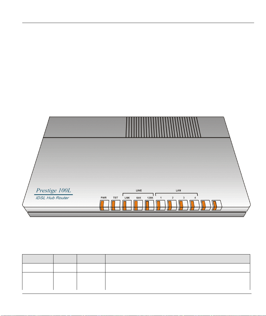
The LEDs on the front panel indicate the operational status of the Prestige.
Prestige 100L IDSL Router
Chapter 2
Figure 2-1 Front Panel
The following table describes the LED functions:
Table 2-1 LED Functions
FUNCTION LEDs ACTIVE DESCRIPTION
Power PWR On The power is on.
System Test TST Off The system is not ready or malfunctioning.
Hardware Installation and Initial Setup 2-1
Page 26
Prestige 100L IDSL Router
FUNCTION LEDs ACTIVE DESCRIPTION
Flashing The system is ready and functioning properly.
IDSL Line
64K On The Prestige is connected at 64K bps line speed.
128K On The Prestige is connected at 128K bps line speed.
Off IDSL link is not ready or failed.LNK
On IDSL link is functioning properly.
LAN 1, 2, 3, 4
Off The Ethernet port is not connected, not ready or has failed.
On The Ethernet port is connected and functioning properly.
Flashing Sending or receiving.
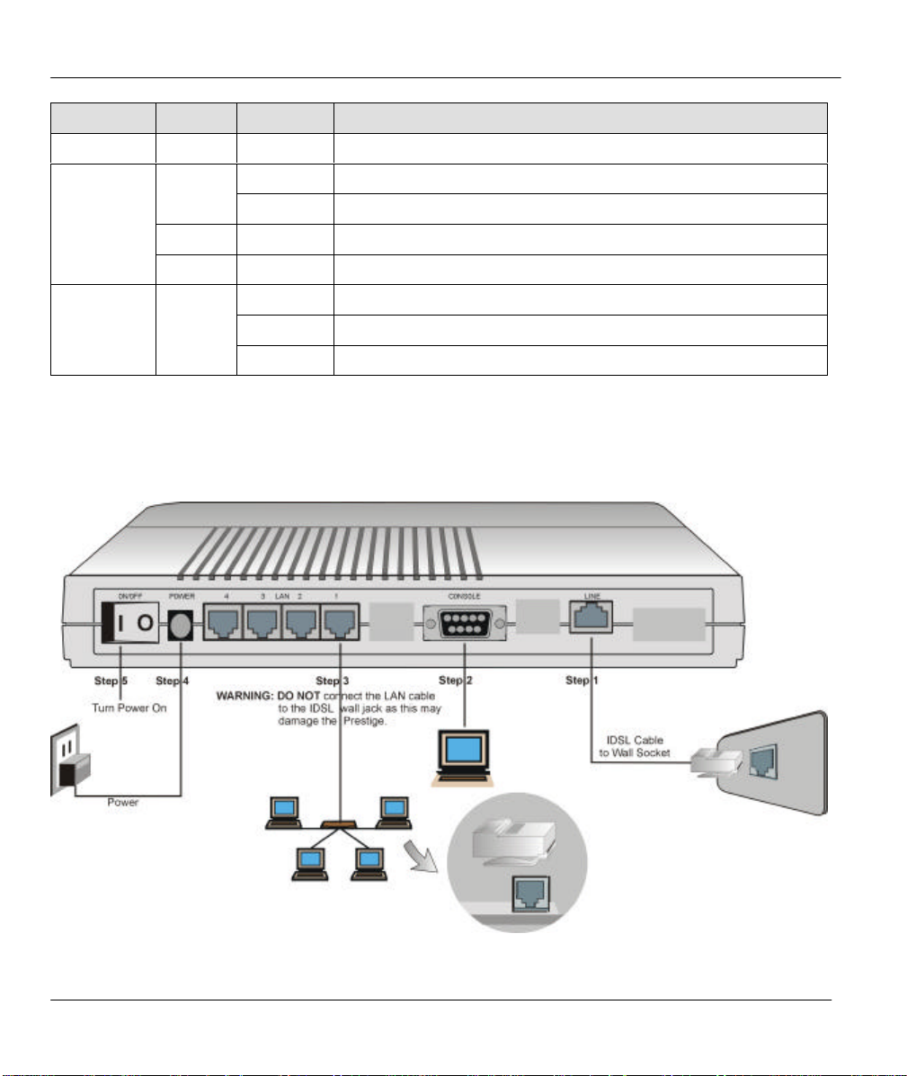
2.2 Prestige 100L Rear Panel and Connections
The following figure shows the rear panel of your Prestige 100L and the connection diagram.
Figure 2-2 Prestige 100L Rear Panel and Connections
2-2 Hardware Installation and Initial Setup
Page 27

Prestige 100L IDSL Router
This section outlines how to connect your Prestige 100L to the LAN and the IDSL line. Refer to the above
diagram to identify all of the ports on your device when you attempt to make the various connections.
NOTE: The IDSL line and Ethernet cable are very similar to each other. It is important
that you use the correct cable for each connection; otherwise, your Prestige could be
damaged.
Connecting Your Computer and Your Prestige
For the initial configuration of your Prestige, use the provided RS-232C cable and communications
software to configure your Prestige. After your Prestige has been successfully installed, you can modify the
configuration through a console port as well as a remote telnet connection.
Step 1. Connecting an IDSL Line to Your Prestige
Plug one end of the IDSL line included in your package into the socket on the rear panel of your Prestige
labeled LINE, and the other end into the IDSL wall jack or another Prestige.
NOTE: The IDSL jack is for IDSL line connection only. Connecting it to a regular phone
line may result in damage to your Prestige.
Step 2. Connecting the RS-232C Cable to Your Prestige
One 9-25 pin adapter is included with your Prestige. To connect an RS-232C cable, connect the 9-pin end
of the cable to the console port on the back panel of the Prestige. Connect the other end to the RS-232C
cable connected to the serial port (COM1, COM2, or any other COM port) of your computer.
Step 3. Connecting an Ethernet Cable to Your Prestige
The Prestige is equipped with a 4-port hub for you to build a 10Base-T Local Area Network (LAN).
10Base-T networks use UTP (Unshielded Twisted Pair) cable and RJ-45 connectors that look like a bigger
telephone plug with 8 pins. Two types of Ethernet cables come with the package:
l Straight through cable (white tag) — connect your computers to your Prestige.
l Crossover cable (red tag) — connect your Prestige to another 10Base-T hub.
Step 4. Connecting the Power Adapter to Your Prestige
Connect the power adapter to the port labeled POWER on the rear panel of your Prestige.
CAUTION: To prevent damage to the Prestige, first make sure you have the correct AC
power adapter specifications (refer to the Appendix section) for your particular
region.
At this point you should have connected the RS-232C cable, the ISDN phone line, the Ethernet cable, and
the power supply.
Step 5. Powering On
You can now power on your Prestige.
2.3 Housing
Your Prestige's ventilated housing has clip-out legs that fit snugly into grooves, enabling compact, sturdy
stacking with airflow between routers. You should not stack more than 4 routers for maximum stability.
Hardware Installation and Initial Setup 2-3
Page 28
Prestige 100L IDSL Router
Press ENTER to continue...
2.4 Power Up Your Prestige
When you power on your Prestige, it performs several internal tests and also does an IDSL line
initialization. After this initialization, your Prestige asks you to press the [Enter] key to continue as shown
on the initial screen.
Initial Screen
Copyright (c) 1994 - 2000 ZyXEL Communications Corp.
ethernet address: 00:a0:c5:01:23:45
Resetting IDSL Firmware.(2) IDSL Firmware Rev : V 09E
...............................
Figure 2-3 Initial Screen
Entering Password
The login screen appears after you press the [Enter] key, prompting you to enter the password as shown on
the next screen.
For your first login, enter the default password 1234. As you type the password, the screen displays an (X)
for each character you type.
Please note that if there is no activity longer than 5 minutes after you log in, your Prestige automatically
logs you out and displays a blank screen. If you see a blank screen, press the [Enter] key to bring up the
login screen again.
Enter Password: XXXX
Figure 2-4 Password Screen
2.5 Navigating the SMT (System Management Terminal)
Interface
The SMT is the interface that you use to configure your Prestige.
Several operations that you should be familiar with before you attempt to modify the configuration are
listed in the following table.
2-4 Hardware Installation and Initial Setup
Page 29
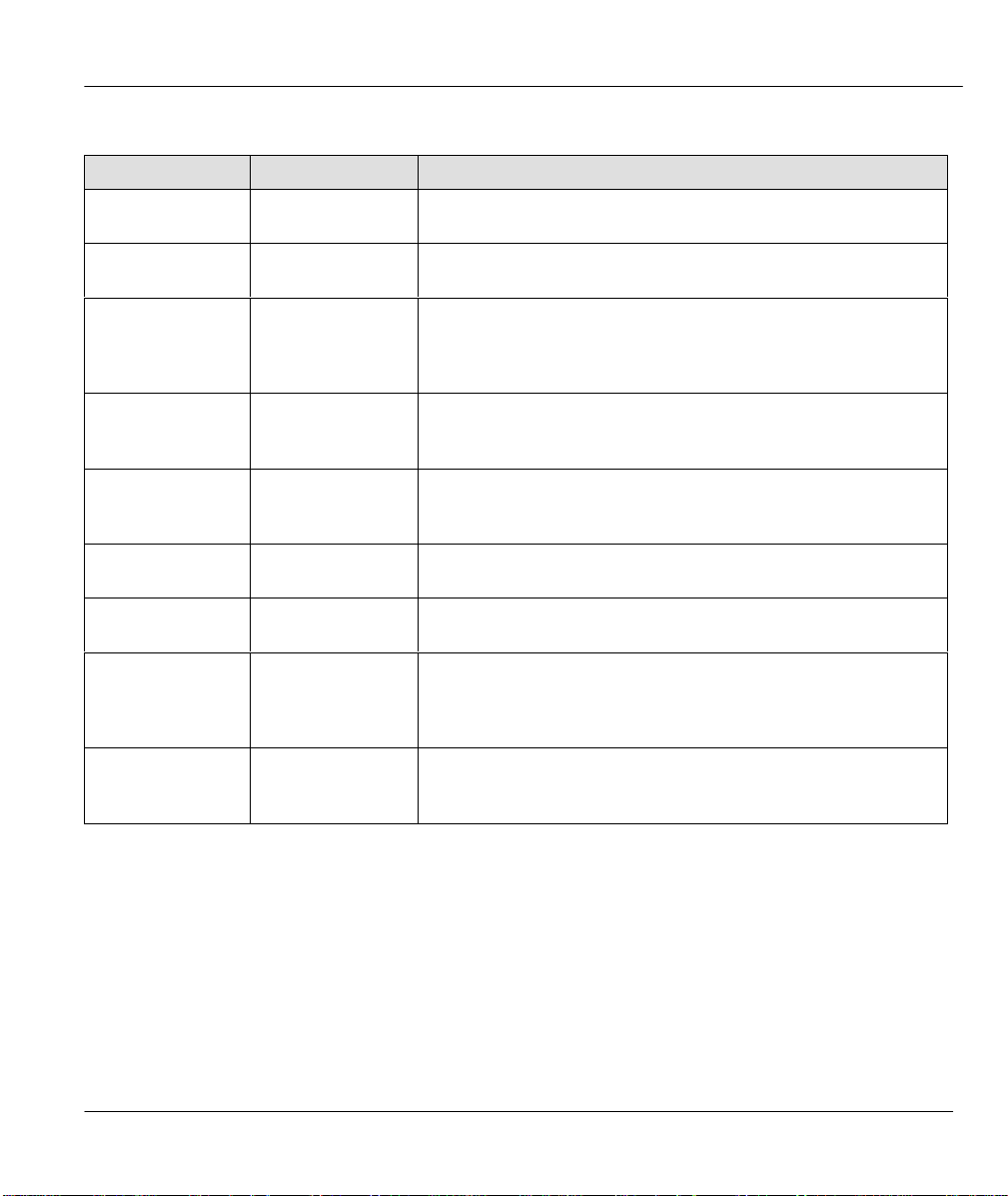
Table 2-2 Main Menu Commands
OPERATION KEYSTROKES DESCRIPTION
Move down to
another menu
Move up to a
previous menu
[Enter] key To move forward to a submenu, type in the number of the
desired submenu and press the [Enter] key.
[Esc] key Press the [Esc] key to move back to the previous menu.
Prestige 100L IDSL Router
Move to a
“hidden” menu
Move the cursor
Enter information Fill in, or
Required fields
N/A fields <N/A> Some of the fields in the SMT shows <N/A>. This symbol refers
Save your
configuration
Exit the SMT
Press [space bar]
to change No to
Yes then press
the [Enter] key
[Enter] key or
[Up]/[Down] arrow
keys
Press [space bar]
to toggle
<?>
[Enter] key Save your configuration by pressing the [Enter] key at the
Type 99, then
press the [Enter]
key.
Fields beginning with “Edit” lead to hidden menus and have a
default setting of No. Press [space bar] to change No to Yes,
then press the [Enter] key to go to a “hidden” menu.
Within a menu, press the [Enter] key to move to the next field.
You can also use the [Up]/[Down] arrow keys to move to the
previous and the next field, respectively.
You need to fill in two types of fields. The first requires you to
type in the appropriate information. The second allows you to
cycle through the available choices by pressing [space bar].
All fields with the symbol <?> must be filled in order to be able to
save the new configuration.
to an option that is Not Applicable.
message [Press ENTER to confirm or ESC to cancel]. Saving
the data on the screen takes you, in most cases to the previous
menu.
Type “99” at the Main Menu prompt and press the [Enter] key to
exit the SMT interface.
2.5.1 Main Menu
After you enter the password, the SMT displays the Prestige 100L Main Menu, as shown in the following
figure.
Hardware Installation and Initial Setup 2-5
Page 30
Prestige 100L IDSL Router
Enter Menu Selection Number:
Copyright (c) 1994 - 2000 ZyXEL Communications Corp.
Prestige 100L Main Menu
Getting Started Advanced Management
1. General Setup
2. WAN Port Setup
3. Ethernet Setup
4. Internet Access Setup
Advanced Applications
11. Remote Node Setup
12. Static Routing Setup
15. SUA Server Setup
21. Filter Set Configuration
22. SNMP Configuration
23. System Password
24. System Maintenance
99. Exit
Figure 2-5 Prestige 100L Main Menu
2.5.2 System Management Terminal Interface Summary
Table 2-3 Main Menu Summary
No. MENU TITLE DESCRIPTION
1 General Setup
2 WAN Port Setup Use this menu to setup the IDSL.
Use this menu to setup general information and enable routing of specific
protocols.
3 Ethernet Setup Use this menu to setup the Ethernet LAN.
4 Internet Access Setup A quick and easy way to setup Internet connection.
11 Remote Node Setup
Use this menu to setup remote node for LAN-to-LAN connection
including Internet connection. Your Prestige has only one remote node.
12 Static Routing Setup
Use this menu to setup static route for different protocols. There are four
static routes for each protocol.
15 SUA Server Setup Use this menu to specify inside servers when SUA is enabled.
21 Filter Set Configuration Use this menu to setup filters to provide security.
22 SNMP Use this menu to setup SNMP-related parameters.
23 System Security Use this menu to setup security-related parameters.
24 System Maintenance This menu provides system status, diagnostics, firmware upload, etc.
99 Exit To exit from SMT and return to the blank (initial) screen.
2-6 Hardware Installation and Initial Setup
Page 31

Prestige 100L IDSL Router
2.6 Changing the System Password
The first thing your should do before anything else is to change the default system password by following
the steps below.
Step 1. Enter 23 in the Main Menu to open Menu 23 – System Password as shown below.
Menu 23 - System Password
Old Password= ?
New Password= ?
Retype to confirm= ?
Enter here to CONFIRM or ESC to CANCEL:
Figure 2-6 Menu 23 – System Security
Step 2. Enter your existing password and press the [Enter] key.
Step 3. Enter your new system password and press the [Enter] key.
Step 4. Re-type your new system password for confirmation and press the [Enter] key.
NOTE: As you type a password, the screen displays an (X) for each character you
type.
2.6.1 Resetting the Prestige
You should already have downloaded the correct file from your nearest ZyXEL FTP server site. See
Chapter 11 for more information on how to transfer the configuration file to your Prestige.
If you have forgotten your password or for some reason cannot access the SMT menu then you need to
reinstall the configuration file. Uploading the configuration file replaces the current configuration file with
the default configuration file. You lost all configurations that you had before and the speed of the console
port is reset to the default of 9600bps with 8 data bit, no parity, 1 stop bit (8n1), and no Flow Control. The
password is reset to the default value of 1234, also.
Turn off the Prestige and begin a Terminal session with the current console port settings. Turn on the
Prestige again. When you see the message "Press Any key to enter Debug Mode within 3 seconds", press
any key to enter debug mode.
Hardware Installation and Initial Setup 2-7
Page 32

Prestige 100L IDSL Router
2.7 General Setup
Menu 1 – General Setup contains administrative and system-related information.
To enter Menu 1 and fill in the required information, follow these steps:
Step 1. Enter 1 in the Main Menu to open Menu 1 – General Setup.
Step 2. The Menu 1 – General Setup screen appears, as shown below. Fill in the required fields.
Menu 1 - General Setup
System Name= xxx
Location=
Contact Person’s Name=
Press ENTER to Confirm or ESC to Cancel:
Figure 2-7 Menu 1 – General Setup
The fields for General Setup are as shown below. System Name is for identification purposes. The
Location is used to enter the geographic location (up to 31 characters) of your Prestige, e.g., San Jose. The
Contact Person’s Name is used to enter the name (up to 30 characters) of the person in charge of your
Prestige, e.g., John Doe. Both the Location and Contact Person’s Name fields are optional.
Table 2-4 General Setup Menu Field
FIELD DESCRIPTION EXAMPLE
System
Name
Location Enter the geographic location (up to 31 characters) of your Prestige (optional
Contact
Person’s
Name
Choose a descriptive name, up to 30 alphanumeric characters long (no
spaces, but dashes “–” and underscores "_" are accepted) for identification
purposes.
field).
Enter the name (up to 30 characters) of the person-in-charge of your
Prestige (optional field).
P100L
San Jose
John Doe
2-8 Hardware Installation and Initial Setup
Page 33

Prestige 100L IDSL Router
2.8 IDSL Setup
This section describes how to configure the IDSL using Menu 2 – IDSL Setup. From the Main Menu,
enter 2 to open Menu 2.
Menu 2 – WAN Port Setup
Service Type: IDSL Client
B Channel Usage= Leased 128K
Press ENTER to Confirm or ESC to Cancel:
Press Space Bar to Toggle.
Figure 2-8 Menu 2 – IDSL Setup
The following table contains instructions on how to configure your IDSL setup.
Table 2-5 IDSL Setup Menu Fields
FIELD DESCRIPTION EXAMPLES
Service
Type
Since the Prestige can only act as an IDSL Client, there is only one
option available: IDSL Client.
IDSL Client
B Channel
Usage
There are three options available: Leased 128K and Leased 64K,
which is used to decide the IDSL line’s speed; or Switch 64K for
Ascend MAX TNT IDSL-module. When the P100L is connected to the
P1600 as the Client router, then this option cannot be set by the user
as it is set on the P1600.
Leased 128K /
Leased 64K /
Switch 64K
2.9 Ethernet Setup
This section describes how to configure the Ethernet-related information using Menu 3 – Ethernet Setup.
From the Main Menu, enter 3 to open Menu 3.
Hardware Installation and Initial Setup 2-9
Page 34

Prestige 100L IDSL Router
Press ENTER to Confirm or ESC to Cancel:
Menu 3 – Ethernet Setup
1. General Setup
2. TCP/IP and DHCP Setup
Enter Menu Selection Number:
Figure 2-9 Menu 3 – Ethernet Setup
2.9.1 General Setup
This menu allows you to specify the filter sets you wish to implement on your Ethernet traffic. From Menu
3 – Ethernet Setup, enter 1 to go to Menu 3.1 – General Ethernet Setup.
Menu 3.1 – General Ethernet Setup
Input Filter Sets:
protocol filters=
device filters=
Output Filter Sets:
protocol filters=
device filters=
Figure 2-10 Menu 3.1 – General Ethernet Setup
NOTE: You may apply up to four filter sets separated by commas.
Input and Output Filter Sets
Filter sets are used to block certain packets to reduce traffic and to prevent a security breach. Filtering is a
very involved subject, so leave these fields blank for the time being. After you have studied filtering in
Chapter 6, come back and define the filter sets. Menu 3.2 is discussed in the next part of the manual. Please
read on.
2-10 Hardware Installation and Initial Setup
Page 35

Prestige 100L IDSL Router
Chapter 3
Internet Access
This chapter shows you how to configure the LAN as well as the WAN of your Prestige for Internet
access.
3.1 TCP/IP and DHCP for LAN
The Prestige has built-in DHCP server capability that assigns IP addresses and DNS servers to systems that
support DHCP client capability.
3.1.1 Factory LAN Defaults
The LAN parameters of the Prestige are preset in the factory with the following values:
1. IP address of 192.168.1.1 with subnet mask of 255.255.255.0 (24 bits).
2. DHCP server enabled with 32 client IP addresses starting from 192.168.1.33.
These parameters should work for the majority of installations. If the parameters are satisfactory, you can
skip to the later section of this chapter to enter the DNS server address(es) if your ISP gives you explicit
DNS server address(es). If you wish to change the factory defaults or to learn more about TCP/IP, please
read on.
3.1.2 IP Address and Subnet Mask
Similar to the houses on a street that shares a common street name, the machines on a LAN share one
common network number, also.
Where you obtain your network number depends on your particular situation. If the ISP or your network
administrator assigns you a block of registered IP addresses, follow their instructions in selecting the IP
addresses and the subnet mask.
If the ISP did not explicitly give you an IP network number, then most likely you have a single user account
and the ISP assigns you a dynamic IP address when the connection is established. If this is the case, it is
recommended that you select a network number from 192.168.0.0 to 192.168.255.0 and you must enable the
Network Address Translation feature of the Prestige. The Internet Assigned Number Authority (IANA)
reserved this block of addresses specifically for private use; please do not use any other number unless you
are told otherwise. Let’s say you select 192.168.1.0 as the network number; which covers 254 individual
addresses, from 192.168.1.1 to 192.168.1.254 (zero and 255 are reserved). In other words, the first 3 numbers
specify the network number while the last number identifies an individual workstation on that network.
Once you have decided on the network number, pick an IP address that is easy to remember, e.g.,
192.168.1.1 (default), for your Prestige. If you chose this then the other default settings are enabled.
Internet Access 3-1
Page 36

Prestige 100L IDSL Router
The subnet mask specifies the network number portion of an IP address. Your Prestige computes the subnet
mask automatically based on the IP address that you entered. You do not need to change the subnet mask
computed by the Prestige unless you are instructed to do otherwise.
3.1.3 Private IP Addresses
Every machine on the Internet must have a unique address. If your networks are isolated from the Internet,
e.g., only between your two branch offices, you can assign any IP addresses to the hosts without problems.
However, the Internet Assigned Numbers Authority (IANA) has reserved the following three blocks of IP
addresses specifically for private networks:
10.0.0.0 - 10.255.255.255
172.16.0.0 - 172.31.255.255
192.168.0.0 - 192.168.255.255
You can obtain your IP address from the IANA, from an ISP, or assigned from a private network. If you
belong to a small organization and your Internet access is through an ISP, the ISP can provide you with the
Internet addresses for your local networks. On the other hand, if you are part of a much larger organization,
you should consult your network administrator for the appropriate IP addresses.
NOTE: Regardless of your particular situation, do not create an arbitrary IP address;
always follow the guidelines above. For more information on address assignment,
please refer to RFC 1597, Address Allocation for Private Internets and RFC 1466,
Guidelines for Management of IP Address Space.
3.1.4 RIP (Routing Information Protocol) Setup
RIP allows a router to exchange routing information with other routers. The RIP Direction field controls the
sending and receiving of RIP packets. When set to Both or Out Only, the Prestige broadcasts its routing
table periodically. When set to Both or In Only, it incorporates the RIP information that it receives; when
set to None, it does not send any RIP packets and ignores any RIP packets received.
The Version field controls the format and the broadcasting method of the RIP packets that the Prestige
sends (it recognizes both formats when receiving). RIP-1 is universally supported; but RIP-2 carries more
information. RIP-1 is probably adequate for most networks, unless you have an unusual network topology.
Both RIP-2B and RIP-2M sends the routing data in RIP-2 format; the difference being that RIP-2B uses
subnet broadcasting while RIP-2M uses multicasting. Multicasting can reduce the load on non-router
machines since they generally do not listen to the RIP multicast address and so does not receive the RIP
packets. However, if one router uses multicasting, then all routers on your network must use multicasting,
also.
By default, RIP direction is set to Both and the Version set to RIP-1.
3-2 Internet Access
Page 37

Prestige 100L IDSL Router
3.1.5 DHCP (Dynamic Host Configuration Protocol) Configuration
DHCP allows the individual clients (workstations) to obtain the TCP/IP configuration at start-up from a
server. Unless you are instructed by your ISP, leave the DHCP at the Server default value. You can
configure the Prestige as a DHCP server or disable it. When configured as a server, the Prestige provides the
TCP/IP configuration for the clients.
IP Pool Setup
The Prestige is pre-configured with a pool of 32 IP addresses starting from 192.168.1.33 to 192.168.1.64.
This configuration leaves 31 IP addresses (excluding the Prestige itself) in the lower range for other server
machines, e.g., server for mail, FTP, telnet, web, etc., that you may have.
DNS (Domain Name System) Server Address
DNS is for mapping a domain name to its corresponding IP address and vice versa, e.g., the IP address of
www.zyxel.com is 204.217.0.2. The DNS server is extremely important because without it, you must know
the IP address of a machine before you can access it.
There are two ways that an ISP disseminates the DNS server addresses. The first is for an ISP to tell a
customer the DNS server addresses, usually in the form of an information sheet, when you sign up. If your
ISP does give you the DNS server addresses, enter them in the DNS Server fields in DHCP Setup. The
second is to leave this field blank, i.e., 0.0.0.0, – in this case the Prestige acts as a DNS proxy.
IP Subnet Mask
A subnet mask is a 32-bit quantity that, when logically ANDed with an IP address, yields the network
number. For instance, the subnet masks for Class A, B, and C without subnetting are 255.0.0.0, 255.255.0.0,
and 255.255.255.0, respectively. To create more network numbers, you shift some bits from the host ID to
the network ID. For instance, to partition a Class C network number 192.68.135.0 into two, you shift 1 bit
from the host ID to the network ID. Thus the new subnet mask is 255.255.255.128; the first subnet have a
network number of 192.68.135.0 with hosts 192.68.135.1 to 192.68.135.126 and the second subnet have a
network number of 192.68.135.128 with hosts 192.68.135.129 to 192.68.135.254. It is recommended that
you use the same subnet mask for all physical networks that share an IP network number. The following table
lists the additional subnet mask bits in dot decimal notations. To use the following table, write down the
original subnet mask and substitute the higher order “0”s with the dot decimal of the additional subnet bits.
For instance, to partition your Class C network 204.247.203.0 with subnet mask 255.255.255.0 into 16
subnets (4 bits), the new subnet mask becomes 255.255.255.240.
Internet Access 3-3
Page 38

Prestige 100L IDSL Router
NUMBER OF BITS DOT DECIMAL
1 128
2 192
3 224
4 240
5 248
6 252
7 254
8 255
Example of Network Properties For LAN Servers With Fixed IP#:
Choose an IP: 192.168.1.2 – 192.168.1.32; 192.168.1.65 – 192.168.1.254
Netmask: 255.255.255.0
Gateway (or default route): 192.168.1.1 (Prestige LAN IP)
DNS server: 192.168.1.1
Domain: (optional)
3-4 Internet Access
Page 39

Prestige 100L IDSL Router
3.2 TCP/IP and DHCP Ethernet Setup
From the Main Menu, enter 3 to open Menu 3 – Ethernet Setup.
Menu 3 – Ethernet Setup
1. General Setup
2. TCP/IP and DHCP Setup
Enter Menu Selection Number:
Figure 3-1 Menu 3 – Ethernet Setup Screen
To edit the TCP/IP and DHCP configuration, enter 2 to open Menu 3.2 – TCP/IP and DHCP Ethernet
Setup as shown in the following figure.
Menu 3.2 - TCP/IP and DHCP Ethernet Setup
DHCP= Server
Configuration:
Size of Client IP Pool= 32
Primary DNS Server= 0.0.0.0
TCP/IP Setup:
Press Space Bar to Toggle.
Client IP Pool Starting Address= 192.168.1.33
Secondary DNS Server= 0.0.0.0
Relay Server Address= N/A
IP Address= 192.168.1.1
IP Subnet Mask= 255.255.255.0
RIP Direction= Both
Version= RIP-1
Press ENTER to Confirm or ESC to CANCEL:
Figure 3-2 Menu 3.2 – TCP/IP and DHCP Ethernet Setup Screen
Internet Access 3-5
Page 40

Prestige 100L IDSL Router
Follow the instructions in the following table on how to configure the DHCP fields.
Table 3-1 LAN DHCP Setup Menu Fields
FIELD DESCRIPTION EXAMPLE
DHCP This field enables/disables the DHCP server. If it is set to Server,
your Prestige acts as a DHCP server. If set to None, DHCP
service is disabled and you must have another DHCP sever on
your LAN, or else the workstation must be manually configured.
When DHCP is set to Server, the following four items need to be
set. If set to Relay, the Prestige acts as a surrogate DHCP
server and relays requests and responses between the remote
server and the clients.
Client IP Pool
Starting Address
Size of Client IP Pool This field specifies the size, or count, of the IP address pool. 32
This field specifies the first of the contiguous addresses in the IP
address pool.
None / Relay /
Server (default)
192.168.1.33
Primary DNS Server
Secondary DNS
Server
Relay Server
Address
Enter the IP addresses of the DNS servers. The DNS servers are
passed to the DHCP clients along with the IP address and the
subnet mask.
When the DHCP is set to Relay, the Prestige relays the DHCP
requests/responses between the PCs and the real DHCP server.
3-6 Internet Access
Page 41

Prestige 100L IDSL Router
Follow the instructions in the following table to configure TCP/IP parameters for the LAN port.
Table 3-2 LAN TCP/IP Setup Menu Fields
FIELD DESCRIPTION EXAMPLE
IP Address Enter the IP address of your Prestige in dotted decimal notation. 192.168.1.1
(default)
IP Subnet Mask
Your Prestige automatically calculates the subnet mask based on
255.255.255.0
the IP address that you assign. Unless you are implementing
subnetting, use the subnet mask computed by the Prestige.
RIP Direction Press [space bar] to select the RIP direction from Both/In
Only/Out Only/None.
Version
Press [space bar] to select the RIP version from RIP-1 / RIP-2B /
RIP-2M.
Both
(default)
RIP-1
(default)
When you have completed this menu, press the [Enter] key at the prompt [Press ENTER to Confirm . . .] to
save your configuration, or press the [Esc] key at any time to cancel.
3.3 Internet Access Setup
The following steps describe the set-up procedure to configure your Prestige for Internet access.
Menu 4 - Internet Access Setup
ISP's Name =
My Login =
My Password =
SUA
Single User Account = Yes
IP Address = 0.0.0.0
Press ENTER to Confirm or ESC to Cancel:
Figure 3-3 Menu 4 – Internet Access Setup
Internet Access 3-7
Page 42

Prestige 100L IDSL Router
The following table describes this screen.
Table 3-3 Internet Access Setup Menu Fields
FIELD DESCRIPTION
ISP’s Name Enter the name of your Internet Service Provider, e.g., myISP. This
information is for identification purposes only.
My Login Enter the login name given to you by your ISP.
My Password Enter the password associated with the login name above.
Single User Account
Please refer to the following section for a more detailed discussion on the
Single User Account feature. The default value is Yes.
IP Address
Please refer to the following section for a more detailed discussion on setting
the IP Address under a Single User Account.
3.4 Single User Account (SUA)
Typically, if there are multiple users on the LAN wanting to concurrently access the Internet, you have to
lease a block of legal, or globally unique, IP addresses from the ISP.
The Single User Account (SUA) feature allows you to have the same benefits as having multiple legal
addresses, but only pay for one IP address, thus saving significantly on the subscription fees. (Check with
your ISP before you enable this feature). SUA supports popular Internet applications such as MS traceroute,
CuSeeMe, IRC, RealAudio, VDOLive, Quake and PPTP with no extra configuration needed.
The IP address for the SUA can be either fixed or dynamically assigned by the ISP. In addition, you can
designate servers, e.g., a web server and a telnet server, on your local network and make them accessible to
the outside world. If you do not define any server, SUA offers the additional benefit of firewall protection. If
no server is defined, all incoming inquiries are filtered out by your Prestige, thus preventing intruders from
probing your network. Your Prestige accomplishes this address sharing by translating the internal LAN IP
addresses to a single address that is globally unique on the Internet. For more information on IP address
translation, refer to RFC 1631, The IP Network Address Translator (NAT).
3.4.1 Advantages of SUA
l SUA is an ideal, cost-effective solution for small offices to access the Internet or other remote TCP/IP
networks.
l SUA supports servers to be accessible to the outside world.
l SUA can provide firewall protection if you do not specify a server. All incoming inquiries are filtered
out by your Prestige.
l UDP and TCP packets can be routed. In addition, partial ICMP, including echo and traceroute, is also
supported.
3-8 Internet Access
Page 43

Prestige 100L IDSL Router
3.4.2 Single User Account Configuration
The steps for configuring your Prestige for Single User Account are identical to the conventional Internet
access with the exception that you need to fill in two extra fields in Menu 4 – Internet Access Setup (please
refer to Figure 3-3). To enable the SUA feature in Menu 4, move the cursor to the Single User Account field
and select Yes (or No to disable SUA). Then follow the instructions on how to configure the SUA fields.
Table 3-4 Single User Account Menu Fields
FIELD DESCRIPTION
Single User Account Select Yes to enable SUA.
IP Address
Press the [Enter] key at the message [Press ENTER to Confirm . . . ] to save your
configuration, or press the [Esc] key at any time to cancel.
If your ISP did not assign you a static IP address, enter [0.0.0.0]
here; otherwise, enter that IP address here.
3.5 Multiple Servers Behind the SUA
If you wish, you can make inside servers for different services, e.g., web or FTP, visible to the outside users,
even though SUA makes your whole internal network appear as a single machine to the outside world. A
service is identified by the port number, e.g., web service is on port 80 and FTP on port 21.
As an example (see the following figure), if you have a web server at 192.168.1.36 and an FTP server at
192.168.1.33, then you need to specify for port 80 (web) the server at IP address 192.168.1.36 and for port 21
(FTP) another at IP address 192.168.1.33.
Please note that a server can support more than one service, e.g., a server can provide both FTP and DNS
service, while another provides only web service. Also, since you need to specify the IP address of a server in
the Prestige, a server must have a fixed IP address and not be a DHCP client whose IP address potentially
changes each time it is powered on.
In addition to the servers for specific services, SUA supports a default server. A service request that does not
have a server explicitly designated for it is forwarded to the default server. If the default server is not defined,
the service request is simply discarded.
Internet Access 3-9
Page 44

Prestige 100L IDSL Router
Figure 3-4 Example of a SUA Topology
To make a server visible to the outside world, specify the port number of the service and the inside IP address
of the server in Menu 15 – SUA Server Setup.
3.5.1 Configuring a Server Behind the SUA
Do the following steps to configure a server behind SUA:
Step 1. Enter 15 in the main menu to go to Menu 15 - SUA Server Setup.
Step 2. Enter the service port number in the Port # field and the inside IP address of the server in the
IP Address field.
Step 3. Press the [Enter] key at the “Press ENTER to confirm …” prompt to save your configuration
after you define all the servers or press the [Esc] key at any time to cancel.
3-10 Internet Access
Page 45

Prestige 100L IDSL Router
Menu 15 - Multiple Server Configuration
------
Port #
1.Default 0.0.0.0
2.21 192.168.1.33
3.23 192.168.1.34
4.25 192.168.1.35
5.80 192.168.1.36
6. 0 0.0.0.0
7. 0 0.0.0.0
8. 0 0.0.0.0
Press ENTER to Confirm or ESC to Cancel:
IP Address
---------------
Figure 3-5 Multiple Server Configuration
The most often used port numbers are shown in the next table. Please refer to RFC 1700 for further
information about port numbers.
Table 3-5 Services as Compared to Port Number
SERVICES PORT NUMBER
FTP (File Transfer Protocol) 21
Telnet 23
SMTP (Simple Mail Transfer Protocol) 25
DNS (Domain Name System) 53
HTTP (Hyper Text Transfer Protocol or WWW, Web) 80
PPTP (Point-to-Point Tunneling Protocol) 1723
Internet Access 3-11
Page 46

Part II:
ADVANCED APPLICATIONS
Advanced Applications (Chapters 4 and 5) describe the advanced applications of your Prestige,
such as Remote Node Setup and IP Static routes.
II
Page 47

Prestige 100L IDSL Router
Chapter 4
Remote Node Setup
This chapter shows you how to configure a remote node.
A remote node is required for placing calls to a remote gateway. A remote node represents both the remote
gateway and the network behind it across an IDSL connection. Note that when you use Menu 4 to set up
Internet access, you are actually configuring a remote node.
Even though you can configure up to four remote nodes, the first active remote node is used to connect to
the remote LAN. It is good practice to keep only one active remote node for your Prestige.
In this chapter, we discuss the parameters that are protocol independent. The protocol dependent
configuration is covered in subsequent chapters. You are also shown how to configure Menu 11.1 Remote
Node Profile, Menu 11.2 – Remote Node PPP Options, Menu 11.3 – Remote Node Network Layer
Options and Menu 11.5 – Remote Node Filter.
4.1 Remote Node Profile
From the Main Menu, select menu option 11 to open Menu 11.1 – Remote Node Profile.
Menu 11.1 - Remote Node Profile
Rem Node Name= Edit PPP Options= No
Active =Yes Rem IP Addr= 0.0.0.0
Incoming:
Rem Login= Session Options:
Rem Password= Edit Filter Sets= No
Outgoing:
My Login=
My Password=
Authen= CHAP/PAP
Press ENTER to Confirm or ESC to Cancel:
Edit IP= No
Figure 4-1 Menu 11.1 – Remote Node Profile
Remote Node Setup 4-1
Page 48

Prestige 100L IDSL Router
Table 4-1 Fields in Menu 11.1
FIELD DESCRIPTION EXAMPLES
Rem Node Name Enter a descriptive name for the remote node. This field can be up
to eight characters.
Active Press the [space bar] to toggle between Yes and No and activate
(deactivate) the remote node.
Incoming:
Rem Login
Incoming: Rem
Password
Outgoing: My
Login
Outgoing: My
Password
Outgoing: Authen This field sets the authentication protocol used for outgoing calls.
Edit PPP Options To edit the PPP options for this Remote Node, move the cursor to
Rem IP Addr This is a required field if Route is set to IP. Enter the IP address of
Edit IP To edit the parameters of the protocols, go to this field, select Yes
Enter the Login name that this Remote Node uses when it calls
into your Prestige. The login name in this field combined with the
Rem Node Password is used to authenticate the incoming calls
from this node.
Enter the password used when this Remote Node calls into your
Prestige.
This is a required field if Call Direction is either Both or Out. Enter
the login name for your Prestige when it calls this Remote Node.
This is a required field if Call Direction is either Both or Out. Enter
the password for your Prestige when it calls this Remote Node.
Your Prestige supports two authentication protocols: PAP
(Password Authentication Protocol) and CHAP (Challenge
Handshake Authentication Protocol).
• PAP sends the user name and password in plain text.
• CHAP scrambles the password before it is sent over the wire.
Generally speaking, CHAP is more secure than PAP, however,
PAP is readily available on more platforms. The recommendation
is to use CHAP whenever possible. Turning off the authentication
is STRONGLY discouraged.
Options for this field are:
• CHAP/PAP – your Prestige tries CHAP when CHAP is
requested by the Remote Node or PAP when PAP is
requested by the Remote Node.
• CHAP – use CHAP only.
• PAP – use PAP only.
this field, use [space bar] to select Yes and press the [Enter] key.
This brings you to Menu 11.2 – Remote Node PPP Options for
more information on configuring PPP options. See the section
Editing PPP Options.
this Remote Node.
and press the [Enter] key. This brings you to Menu 11.3 – Remote
Node Network Layer Options. For more information on filling out
this screen, please refer to the chapter pertaining to your specific
protocol.
LAoffice
Yes/No
Standard
jim
*****
CHAP/PAP /
CHAP / PAP
No/Yes
Yes/No
4-2 Remote Node Setup
Page 49

Prestige 100L IDSL Router
Session Options:
Edit Filter Sets
In these fields, select which filter set(s) you would like to
implement to filter the incoming and outgoing traffic between this
Remote Node and your Prestige. You can choose from 12
different filter sets. In addition, you can link up to 4 filter sets
together for further customization (e.g., 1, 5, 9, 12). Note that
spaces and “,” are accepted in this field.
For more information on customizing your filter sets, see Chapter
6. The default is blank, i.e., no filters defined.
No/Yes
4.1.1 Editing PPP Options
Menu 11.2 - Remote Node PPP Options
Encapsulation = Standard PPP
Compression = No
Press ENTER to Confirm or ESC to Cancel:
Press Space Bar to Toggle.
Figure 4-2 Menu 11.2 Remote Node PPP Options
Table 4-2 Fields in Menu 11.2 (PPP Options )
FIELD DESCRIPTION
Encapsulation Select CCP (Compression Control Protocol) for the PPP
or MP link. There are two options in this field:
• Standard PPP – Standard PPP options is used.
• CISCO PPP – CISCO PPP options is used.
Compression Turns on Stac Compression. The default for this field is
Off.
Once you have completed Menu 11.2 – Remote Node PPP Options, press the [Enter] key at the message
“Press ENTER to Confirm . . . to confirm your selections or press ESC to cancel your selections”.
EXAMPLES
Standard
PPP / CISCO
PPP
No/Yes
4.2 Editing TCP/IP Options
Move the cursor to the Edit IP field in Menu 11.1, then press the [space bar] to toggle and set the value to
Yes. Press the [Enter] key to open Menu 11.3 – Remote Node Network Layer Options.
This section shows you how to configure your Prestige for TCP/IP. Depending on your particular
applications, you need to configure different menus. For instance, Internet access is the most common
application of TCP/IP. For this application, you should configure Menu 4. Configuration for other
applications is shown in the following sections.
Remote Node Setup 4-3
Page 50

Prestige 100L IDSL Router
LAN-to-LAN Application
A typical LAN-to-LAN application is to use your Prestige to call from a branch office to the headquarters,
as depicted in the following diagram.
Figure 4-3 LAN-to-LAN Application
For the branch office, you need to configure a Remote Node in order to dial out to headquarters.
Additionally, you may also need to configure Static Routes if some services reside beyond the immediate
remote LAN.
Remote Node Setup
Follow the procedure in the preceding Chapter to fill the protocol-independent parameters in Menu 11,
Remote Node Profile. For the protocol-dependent parameters, follow the instructions below.
Table 4-3 Protocol-dependent Parameters for Remote Node Setup
FIELD DESCRIPTION
IP Address Enter the IP address of the gateway at the remote site (in
this case, headquarters). If the remote router is using a
different IP address than the one entered here, your
Prestige drops the call.
Edit IP Press [space bar] to change it to Yes and press the
[Enter] key to go to Menu 11.3 – Remote Node Network
Layer Options menu as shown in the following figure.
EXAMPLES
No/Yes
4-4 Remote Node Setup
Page 51

Prestige 100L IDSL Router
Menu 11.3 - Remote Node Network Layer Options
Rem IP Addr: 0.0.0.0
Rem Subnet Mask = 0.0.0.0
My WAN Addr = 0.0.0.0
Single User Account = Yes
Metric = 2
Private = No
RIP Direction = Both
Version = RIP-2B
Enter here to CONFIRM or ESC to CANCEL:
Figure 4-4 Remote Node Network Layer Options
The next table gives you instructions about configuring remote node network layer options.
Table 4-4 Remote Node Network Layer Options Menu Fields
FIELD DESCRIPTION EXAMPLE
Rem IP Addr This shows the IP address you entered for this Remote Node in the
previous menu.
Rem Subnet
Enter the subnet mask for the remote network.
Mask
My WAN Addr Some implementations, especially the UNIX derivatives, require
hosts on both ends of the ISDN link to have separate addresses
from the LAN, and that the addresses must have the same network
number. If this is the case, enter the IP address assigned to the
WAN.
Single User
Account
This field set to Yes to enable the Single User Account (Network
Address Translation) feature for this site. Use [space bar] to toggle
Yes/No
between Yes and No.
Metric Metric represents the “costs” of transmission for routing purposes. IP
routing uses hop count as the measurement of cost, with a minimum
of 1 for directly connected networks. Enter a number that
approximates the cost for this link. The number need not be precise,
but it must be between 1 and 16. In practice, 2 or 3 is usually a good
number.
Private
This parameter determines if your Prestige includes the route
No/Yes
to this Remote Node in its RIP broadcasts. If set to Yes, this
route is kept private and not included in RIP broadcast. If No,
the route to this Remote Node is propagated to other hosts
through RIP broadcasts.
RIP Direction This parameter determines how your Prestige handles RIP (Routing Both/In
Remote Node Setup 4-5
Page 52

Prestige 100L IDSL Router
FIELD DESCRIPTION EXAMPLE
Information Protocol), and the default is Both. If set to Both, your
Prestige broadcasts its routing table on the WAN, and incorporate
RIP broadcasts by the other router into its routing table. If set to In
Only, your Prestige does not broadcast its routing table on the WAN;
if set to Out Only, your Prestige broadcasts its routing table but
ignores any RIP broadcast packets that it receives. If set to None,
your Prestige does not participate in any RIP exchange with other
routers. Usually, you should leave this parameter at its default of
Both and RIP propagates the routing information automatically.
Version Press [space bar] to select the RIP version from RIP-1, RIP-2B and
RIP-2M.
Once you have completed filling in the Remote Node Network Layer Options Menu, press the [Enter] key
to return to Menu 11. Press the [Enter] key at the message [Press ENTER to Confirm . . .] to save your
configuration, or press the [Esc] key at any time to cancel.
Only/Out
Only/None
RIP-2B/
RIP-2M/
RIP-1
4-6 Remote Node Setup
Page 53

Prestige 100L IDSL Router
4.3 Remote Node Filter
Move the cursor to the field Edit Filter Sets in Menu 11.1, then press [space bar] to toggle and set the
value to Yes. Press the [Enter] key to open Menu 11.5 – Remote Node Filter.
Use Menu 11.5 to specify the filter set(s) to apply to the incoming and outgoing traffic between this remote
node and the Prestige and to prevent certain packets from triggering calls. You can specify up to 4 filter sets
separated by a comma, e.g., 1, 5, 9, 12, in each filter field. The default is no filters.
Note that spaces are accepted in this field.
Menu 11.5 - Remote Node Filter
Input Filter Sets:
protocol filters=
device filters=
Output Filter Sets:
protocol filters=
device filters=
Enter here to CONFIRM or ESC to CANCEL:
Figure 4-3 Remote Node Filter
Remote Node Setup 4-7
Page 54

Page 55

Prestige 100L IDSL Router
Chapter 5
IP Static Route Setup
This chapter shows you how to configure static routes with your Prestige.
Static routes tell the Prestige routing information that it cannot learn automatically through other means.
This can arise in cases where RIP is disabled on the LAN or a remote network is beyond the one that is
directly connected to a remote node.
Each remote node specifies only the network to which the gateway is directly connected, and the Prestige
has no knowledge of the networks beyond. For instance, the Prestige knows about network (N2) in the
following diagram through remote node Router 1. However, the Prestige is unable to route a packet to
network (N3) because it does not know that there is a route through remote node Router 2. The static routes
are for you to tell the Prestige about the networks beyond the remote nodes.
Figure 5-1 Example of an IP Static Route Setup
IP Static Route Setup 5-1
Page 56

Prestige 100L IDSL Router
5.1 IP Static Route Setup
You configure IP static routes in Menu 12.1, by selecting one of the IP static routes as shown below. Enter
12 from the Main Menu.
Menu 12 - IP Static Route Setup
1. ________
2. ________
3. ________
4. ________
5. ________
6. ________
7. ________
8. ________
Enter selection number:
Figure 5-2 Menu 12 – IP Static Route Setup
Now, enter the index number of one of the static routes you want to configure.
Menu 12.1 - Edit IP Static Route
Route #: 1
Route Name= ?
Active= No
Destination IP Address= ?
IP Subnet Mask= ?
Gateway IP Address= ?
Metric= 2
Private= No
Press ENTER to CONFIRM or ESC to CANCEL:
Figure 5-3 Menu 12. 1 – Edit IP Static Route
`The following table describes the IP Static Route Menu fields.
5-2 IP Static Route Setup
Page 57

Prestige 100L IDSL Router
Table 5-1 IP Static Route Menu Fields
FIELD DESCRIPTION
Route # This is the index number of the static route that you chose in Menu 12.
Route Name Enter a descriptive name for this route. This is for identification purposes only.
Active This field allows you to activate/deactivate this static route.
Destination IP
Address
IP Subnet Mask Enter the IP subnet mask for this destination.
Gateway IP
Address
Metric Metric represents the “cost” of transmission for routing purposes. IP routing uses hop
Private This parameter determines if the Prestige includes the route to this remote node in its
Once you have completed filling in this menu, press the [Enter] key at the message [Press ENTER to
Confirm . . .] to save your configuration, or press the [Esc] key to cancel.
This parameter specifies the IP network address of the final destination. Routing is
always based on network number. If you need to specify a route to a single host, use
a subnet mask of 255.255.255.255 in the subnet mask field to force the network
number to be identical to the host ID.
Enter the IP address of the gateway. The gateway is an immediate neighbor of your
Prestige that forwards the packet to the destination. On the LAN, the gateway must be
a router on the same segment as your Prestige; over the WAN, the gateway must be
the IP address of one of the Remote Nodes.
count as the measurement of cost, with a minimum of 1 for directly connected
networks. Enter a number that approximates the cost for this link. The number need
not be precise, but it must be between 1 and 15. In practice, 2 or 3 are usually good
numbers.
RIP broadcasts. If set to Yes, this route is kept private and not included in RIP
broadcast. If No, the route to this remote node is propagated to other hosts through
RIP broadcasts.
IP Static Route Setup 5-3
Page 58

Part III:
ADVANCED MANAGEMENT
Chapters 6 to 11 provide information on Prestige Filtering, Simple Network Management Protocol
(SNMP), System Security, System Information and Diagnosis, Transferring Files and Telnet
Configuration and Capabilities.
III
Page 59

Page 60

Prestige 100L IDSL Router
Chapter 6
Filter Configuration
This chapter shows you how to create and apply filter(s).
6.1 About Filtering
Your Prestige uses filters to decide whether to allow passage of a data packet and/or to make a call. There
are two types of filter applications: data filtering and call filtering. Filters are subdivided into device and
protocol filters, which are discussed later.
Data filtering screens the data to determine if the packet should be allowed to pass. Data filters are divided
into incoming and outgoing filters, depending on the direction of the packet relative to a port. Data filtering
can be applied on either the WAN side or the Ethernet side. Call filtering is used to determine if a packet
should be allowed to trigger a call. Outgoing packets must undergo data filtering before they encounter call
filtering as shown in the following figure.
Call Filtering
Outgoing
Packet
Data
Filtering
Match MatchMatch
Drop
packet
No
match
Call Filters
Drop packet
if line not up
Built-in
default
No
match
Or Or
Send packet
but do not reset
Idle Timer
User-defined
Call Filters
(if applicable)
Drop packet
if line not up
Send packet
but do not reset
Idle Timer
No
match
Active Data
Initiate call
if line not up
Send packet
and reset
Idle Timer
Figure 6-1 Outgoing Packet Filtering Process
For incoming packets, your Prestige applies data filters only. Packets are processed depending upon
whether a match is found. The following sections describe how to configure filter sets.
Filters 6-1
Page 61

Prestige 100L IDSL Router
6.1.1 The Filter Structure of the Prestige
A filter set consists of one or more filter rules. Usually, you would group related rules, e.g., all the rules for
NetBIOS, into a single set and give it a descriptive name. The Prestige allows you to configure up to twelve
filter sets with six rules in each set, for a total of 72 filter rules in the system. You cannot mix device filter
rules and protocol filter rules within the same set. You can apply up to four filter sets to a particular port to
block multiple types of packets. With each filter set having up to six rules, you can have a maximum of 24
rules active for a single port.
Three sets of factory default filter rules have been configured in Menu 21 to prevent NetBIOS traffic from
triggering calls and to prevent incoming telnetting. A summary of their filter rules is shown in the figures
that follow.
The following diagram illustrates the logic flow when executing a filter rule.
6-2 Filters
Page 62

Filter Set
Prestige 100L IDSL Router
Start
Packet
intoFilter
Fetch First
Filter Set
Fetch Next
Filter Set
Yes
Next Filter Set
Available?
No
No
Fetch Next
Filter Rule
Yes
Next filter
Rule
Available?
Check
Next
Rule
Fetch First
Filter Rule
No
Active?
Execute
Filter Rule
Drop
Yes
Yes
Forward
Accept PacketDrop Packet
Figure 6-2 Filter Rule Process
You can apply up to four filter sets to a particular port to block multiple types of packets. With each filter
set having up to six rules, you can have a maximum of 24 rules active for a single port.
Filters 6-3
Page 63

Prestige 100L IDSL Router
6.2 Configuring a Filter Set
To configure a filter set, follow the procedure below.
Step 1. Select option 21. Filter Set Configuration from the Main Menu to open Menu 21.
Menu 21 - Filter Set Configuration
Filter
Set #
-----1
2
3
4
5
6
Enter Filter Set Number to Configure= 0
Edit Comments=
Comments
-----------------NetBIOS_WAN
NetBIOS_LAN
______________
______________
______________
______________
Press ENTER to CONFIRM or ESC to CANCEL:
Figure 6-3 Menu 21 – Filter Set Configuration
Step 2. Select the filter set you wish to configure (nos. 1-12) and press the [Enter] key.
Step 3. Enter a descriptive name or comment in the Edit Comments field and press the [Enter] key.
Step 4. Press the [Enter] key at the message: [Press ENTER to confirm] to open Menu 21.1.1 – Filter
Rules Summary.
Filter
Set #
-----7
8
9
10
11
12
Comments
-----------------______________
______________
______________
______________
______________
______________
6-4 Filters
Page 64

Prestige 100L IDSL Router
- - ---- -------------------------------------------- --------- - - -
Menu 21.1 - Filter Rules Summary
# A Type Filter Rules M m n
1 Y IP Pr=6, SA=0.0.0.0, DA=0.0.0.0, DP=137 N D N
2 Y IP Pr=6, SA=0.0.0.0, DA=0.0.0.0, DP=138 N D N
3 Y IP Pr=6, SA=0.0.0.0, DA=0.0.0.0, DP=139 N D N
4 Y IP Pr=17, SA=0.0.0.0, DA=0.0.0.0, DP=137 N D N
5 Y IP Pr=17, SA=0.0.0.0, DA=0.0.0.0, DP=138 N D N
6 Y IP Pr=17, SA=0.0.0.0, DA=0.0.0.0, DP=139 N D F
Enter Filter Rule Number (1-6) to Configure:
Figure 6-4 Filter Rules Summary
Filters 6-5
Page 65

Prestige 100L IDSL Router
6.2.1 Filter Rules Summary Menu
This screen shows the summary of the existing rules in the filter set. The following tables contain a brief
description of the abbreviations used in the previous menus.
Table 6-1 Abbreviations Used in the Filter Rules Summary Menu
ABBREVIATIONS DESCRIPTION DISPLAY
# Refers to the filter rule number (1 to 6).
A Shows whether the rule is active or
not.
Type Refers to the type of filter rule.
This shows GEN for generic, IP for
TCP/IP
Filter Rules The filter rule parameters are
displayed here (see the following).
M
m
n
Refers to More.
[Y] means an action cannot yet be
taken as there are more rules to
check, which are concatenated with
the present rule to form a rule chain.
When the rule chain is complete an
action can be taken.
[N] means you can now specify an
action to be taken i.e., forward the
packet, drop the packet or check the
next rule. For the latter, the next rule is
independent of the rule just checked.
If More is Yes, then Action Matched
and Action Not Matched is N/A.
Refers to Action Matched.
[F] means to forward the packet
immediately and skip checking the
remaining rules.
Refers to Action Not Matched.
[F] means to forward the packet
immediately and skip checking the
remaining rules.
[Y] means the filter rule is active.
[N] means the filter rule is inactive.
[GEN] for Generic
[IP] for TCP/IP
[Y] means there are more rules to check.
[N] means there are no more rules to
check.
[F] means to forward the packet.
[D] means to drop the packet.
[N] means check the next rule.
[F] means to forward the packet.
[D] means to drop the packet.
[N] means check the next rule.
6-6 Filters
Page 66

Prestige 100L IDSL Router
The protocol dependent filter rules abbreviation are listed as follows:
l If the filter type is IP, the following abbreviations listed in the following table are used.
Table 6-2 Abbreviations Used If Filter Type Is IP
ABBREVIATION DESCRIPTION
Pr Protocol
SA Source Address
SP Source Port number
DA Destination Address
DP Destination Port number
l If the filter type is GEN (generic), the abbreviations listed in the following table are used.
Table 6-3 Abbreviations Used If Filter Type Is GEN
ABBREVIATION DESCRIPTION
Off Offset
Len Length
Refer to the next section for information on configuring the filter rules.
6.2.2 Configuring a Filter Rule
To configure a filter rule, type its number in Menu 21.1 - Filter Rules Summary and press the [Enter] key
to open Menu 21.1.1 for the rule.
To speed up filtering, all rules in a filter set must be of the same class, i.e., protocol filters or generic filters.
The class of a filter set is determined by the first rule that you create. When applying the filter sets to a port,
separate menu fields are provided for protocol and device filter sets. If you include a protocol filter set in a
device filter field or vice versa, the Prestige warns you and you are not allowed to save.
6.2.3 TCP/IP Filter Rule
This section shows you how to configure a TCP/IP filter rule. TCP/IP rules allow you to base the rule on
the fields in the IP and the upper layer protocol, e.g., UDP and TCP, headers.
To configure a TCP/IP rule, select TCP/IP Filter Rule from the Filter Type field and press the [Enter] key
to open Menu 21.1.1.1 – TCP/IP Filter Rule, as shown in the following figure.
Filters 6-7
Page 67

Prestige 100L IDSL Router
Menu 21.1.1 - TCP/IP Filter Rule
Filter #: 1,1
Filter Type= TCP/IP Filter Rule
Active= Yes
IP Protocol= 6 IP Source Route= No
Destination: IP Addr= 0.0.0.0
Source: IP Addr= 0.0.0.0
TCP Estab= No
More= No Log= None
Action Matched= Drop
Action Not Matched= Check Next Rule
Press ENTER to Confirm or ESC to Cancel:
Press Space Bar to Toggle.
IP Mask= 0.0.0.0
Port #= 137
Port # Comp= Equal
IP Mask= 0.0.0.0
Port #=
Port # Comp= None
Figure 6-3 Menu 21.1.1 – TCP/IP Filter Rule
The following table describes how to configure your TCP/IP filter rule.
Table 6-4 TCP/IP Filter Rule Menu Fields
FIELD DESCRIPTION OPTION
Active This field activates/deactivates the filter rule. Yes/No
IP Protocol
Protocol refers to the upper layer protocol, e.g., TCP is 6,
0 to 255
UDP is 17 and ICMP is 1. This value must be between 0
and 255.
IP Source Route If Yes, the rule applies to packet with IP source route
Yes/No
option; else the packet must not have source route option.
The majority of IP packets do not have source route.
Destination: IP
Address
Destination: IP
Enter the destination IP Address of the packet you wish to
filter. This field is disregarded if it has a 0.0.0.0 value.
Enter the IP mask to apply to the Destination: IP Addr. IP address
IP address
Mask
Destination: Port # Enter the destination port of the packets that you wish to
0 to 65535
filter. The range of this field is 0 to 65535. This field is
disregarded if it has a 0 value.
6-8 Filters
Page 68

Prestige 100L IDSL Router
FIELD DESCRIPTION OPTION
Destination: Port #
Comp
Source: IP Address Enter the source IP Address of the packet you wish to
Source: IP Mask Enter the IP mask to apply to the Source: IP Addr. IP Mask
Source: Port #
Source: Port #
Comp
TCP Estab
More
Log Select the logging option from the following:
Action Matched Select the action for a matching packet. Check Next Rule
Action Not Matched
Once you have completed filling in Menu 21.1.1.1 - TCP/IP Filter Rule, press the [Enter] key at the
message [Press Enter to Confirm] to save your configuration, or press the [Esc] key to cancel. This data
is displayed on Menu 21.1.1 - Filter Rules Summary.
Select the comparison to apply to the destination port in
the packet against the value given in Destination: Port #.
filter. This field is disregarded if it has a 0.0.0.0 value.
Enter the source port of the packets that you wish to filter.
The range of this field is 0 to 65535. This field is
disregarded if it has a 0 value.
Select the comparison to apply to the source port in the
packet against the value given in Source: Port #.
This field is applicable only when IP Protocol field is 6,
TCP. If Yes, the rule matches only established TCP
connections; or else the rule matches all TCP packets.
If Yes, a matching packet is passed to the next filter rule
before an action is taken; or else the packet is disposed of
according to the action fields.
If More is Yes, then Action Matched and Action Not
Matched is N/A.
l None – No packet is logged.
l Action Matched – Only packets that match the rule
parameters are logged.
l Action Not Matched – Only packets that do not
match the rule parameters are logged.
l Both – All packets are logged.
Select the action for a packet not matching the rule.
None/Less/Greater/
Equal/Not Equal
IP Address
0 to 65535
None/Less/Greater/
Equal/Not Equal
Yes/No
Yes/No
None
Action Matched
Action Not Matched
Both
Forward
Drop
Check Next Rule
Forward
Drop
The following diagram illustrates the logic flow of an IP filter.
Filters 6-9
Page 69

Prestige 100L IDSL Router
Packet
into IP Filter
Filter Active?
Yes
Apply SrcAddrMask
to Src Addr
Check Src
IP Addr
Matched
Apply DestAddrMask
to Dest Addr
Check Dest
IP Addr
Matched
Check
IP Protocol
Matched
Check Src &
Dest Port
Matched
More?
No
Not Matched
Not Matched
Not Matched
Not Matched
Yes
No
Action Matched
Drop
Drop Packet Accept Packet
Check Next Rule
Forward
Check Next Rule
Check Next Rule
Action Not Matched
Drop Forward
Figure 6-4 Executing an IP Filter
6-10 Filters
Page 70

Prestige 100L IDSL Router
6.2.4 Generic Filter Rule
This section shows you how to configure a generic filter rule. The purpose of generic rules is to allow you
to filter non-IP packets. For IP, it is generally easier to use the IP rules directly.
For generic rules, the Prestige treats a packet as a byte stream as opposed to an IP or IPX packet. You
specify the portion of the packet to check with the Offset (from 0) and the Length fields, both in bytes. The
Prestige applies the Mask (bit-wise ANDing) to the data portion before comparing the result against the
Value to determine a match. The Mask and Value are specified in hexadecimal numbers. Note that it takes
two hexadecimal digits to represent a byte, so if the length is 4, the value in either field takes 8 digits, e.g.,
FFFFFFFF.
To configure a generic rule, select Generic Filter Rule in the Filter Type field in the Menu 21.3.1 and press
the [Enter] key to open Generic Filter Rule, as shown below.
Menu 21.3.1 - Generic Filter Rule
Filter #: 3,1
Filter Type= Generic Filter Rule
Active= No
Offset= 0
Length= 0
Mask= N/A
Value= N/A
More= No Log= None
Action Matched= Check Next Rule
Action Not Matched= Check Next Rule
Press ENTER to Confirm or ESC to Cancel:
Press Space Bar to Toggle.
Figure 6-5 Menu 21.3.1 – Generic Filter Rule
Filters 6-11
Page 71

Prestige 100L IDSL Router
The following table describes the fields in the Generic Filter Rule Menu.
Table 6-5 Generic Filter Rule Menu Fields
FIELD DESCRIPTION OPTION
Filter # This is the filter set, filter rule coordinates, i.e., 2,3 refers to the second filter
set and the third rule of that set.
Filter Type
Active Select Yes to turn on the filter rule. Yes/No
Offset Enter the starting byte of the data portion in the packet that you wish to
Length
Mask
Value Enter the value (in Hexadecimal) to compare with the data portion.
More If Yes, a matching packet is passed to the next filter rule before an action is
Log Select the logging option from the following:
Action
Matched
Action Not
Matched
Once you have completed filling in Menu 21.4.1.1 – Generic Filter Rule, press the [Enter] key at the
message [Press Enter to Confirm] to save your configuration, or press the [Esc] key to cancel. This data is
now displayed on Menu 21.1.1 – Filter Rules Summary.
Use [space bar] to toggle between both types of rules. Parameters
displayed below each type are different.
compare. The range for this field is from 0 to 255.
Enter the byte count of the data portion in the packet that you wish to
compare. The range for this field is 0 to 8.
Enter the mask (in Hexadecimal) to apply to the data portion before
comparison.
taken; else the packet is disposed of according to the action fields.
If More is Yes, then Action Matched and Action Not Matched are N/A.
l None – No packet is logged.
l Action Matched – Only packets that match the rule parameters are
logged.
l Action Not Matched – Only packets that do not match the rule
parameters are logged.
l Both – All packets are logged.
Select the action for a matching packet. Check Next
Select the action for a packet not matching the rule. Check Next
Generic Filter
Rule / TCP/IP
Filter Rule
Default = 0
Default = 0
Yes/No
None
Action
Matched
Action Not
Matched
Both
Rule
Forward
Drop
Rule
Forward
Drop
6-12 Filters
Page 72

Prestige 100L IDSL Router
6.3 Example Filter
Let us look at the third default ZyXEL filter, TELNET_WAN as an example. This filter is designed to
block outside users telnetting into the Prestige.
Figure 6-6 Telnet Filter Example
Step 1. Enter 21 from the Main Menu to open Menu 21 – Filter Set Configuration.
Step 2. Enter the index of the filter set you wish to configure (in this case, 3) and press the [Enter] key.
Step 3. Enter a descriptive name or comment in the Edit Comments field (in this case TELNET_WAN)
and press the [Enter] key.
Step 4. Press the [Enter] key at the message: [Press ENTER to confirm] to open Menu 21.1.1 – Filter
Rules Summary.
Step 5. Enter 1 to configure the first filter rule (the only filter rule of this set). Make the entries in this
menu as shown in the following figure.
Filters 6-13
Page 73

Prestige 100L IDSL Router
Press Space Bar to Toggle.
Press the [space bar] to choose
Select Yes to make the rule
The port number for the telnet
Select Equal
There are no
Select Drop here so that
Select Forward here so that
more rules to
check.
the packet is dropped if
its destination is the
telnet port.
Menu 21.1.1 - TCP/IP Filter Rule
Filter #: 3,1
Filter Type= TCP/IP Filter Rule
Active= Yes
IP Protocol= 6 IP Source Route= No
Destination: IP Addr= 0.0.0.0
Source: IP Addr= 0.0.0.0
TCP Estab= No
More= No Log= None
Action Matched= Drop
Action Not Matched= Forward
Press ENTER to Confirm or ESC to Cancel:
IP Mask= 0.0.0.0
Port #= 23
Port # Comp= Equal
IP Mask= 0.0.0.0
Port #= 0
Port # Comp= None
here as we are
looking for
packets going to
port 23 only.
the packet is forwarded if its
destination is not the telnet
port.
this filter rule type. The first
filter rule type determines all
subsequent filter types within a
set.
active.
6 is the TCP protocol.
service (TCP protocol) is 23.
See RFC 1700 for port numbers
of well-known services.
Figure 6-7 Example Filter – Menu 21.1.1
When you press the [Enter] key to confirm, the following screen appears. Note that there is only one filter
rule in this set.
6-14 Filters
Page 74

Prestige 100L IDSL Router
This shows you that you have
M = N means an action can be taken
Menu 21.2 - Filter Rules Summary
# A Type Filter Rules M m n
- - ---- --------------------------------------------------------------- - - 1 Y IP Pr=6, SA=0.0.0.0, DA=0.0.0.0, DP=23 N D F
2 N
3 N
4 N
5 N
6 N
Enter Filter Rule Number (1-6) to Configure: 1
configured and activated (A =
Y) a TCP/IP filter rule (Type =
IP, Pr = 6) for destination
telnet ports (DP = 23).
Figure 6-8 Example Filter Rules Summary – Menu 21.1.3
After you have created the filter set, you must apply it.
Step 1. Enter 11 from the main menu to go to Menu 11.
Step 2. Go to the Edit Filter Sets field, press [space bar] to toggle Yes to No and press the [Enter]
key.
Step 3. This brings you to Menu 11.5. Apply the TELNET_WAN filter set (filter set 3) as shown in
Figure 6-10.
Filters 6-15
immediately. The action is to drop the
packet (m = D) if the action is matched and
to forward the packet immediately (n = F) if
the action is not matched no matter whether
there are more rules to be checked (there are
not in this example).
Page 75

Prestige 100L IDSL Router
Factory
6.4 Applying a Filter and Factory Defaults
This section shows you where to apply the filter(s) after you designed it (them). Three sets of factory
default filter rules have been configured in Menu 21 to prevent NetBIOS traffic from triggering calls and to
prevent incoming telnetting.
6.4.1 Ethernet Traffic
You seldom need to filter Ethernet traffic; however, the filter sets may be useful to block certain packets,
reduce traffic and prevent security breaches. Go to Menu 3.1 (shown below) and enter the number(s) of the
filter set(s) that you want to apply as appropriate. You can choose up to four filter sets (from twelve) by
entering their numbers separated by commas, e.g., 3, 4, 6, 11. Input filter sets filter incoming traffic to the
Prestige and Output filter sets filter outgoing traffic from the Prestige. The factory default set,
NetBIOS_LAN, is inserted in protocol filters field under Input Filter Sets in Menu 3.1 to block NetBIOS
traffic to the Prestige from the LAN.
Menu 3.1 – General Ethernet Setup
Input Filter Sets:
protocol filters= 2
device filters=
Output Filter Sets:
Protocol filters=
device filters=
Press ENTER to Confirm or ESC to Cancel:
Default
Filter
Figure 6-9 Filtering Ethernet Traffic
6.4.2 Remote Node Filters
Go to Menu 11.5 (shown below) and enter the number(s) of the filter set(s) as appropriate. You can cascade
up to four filter sets by entering their numbers separated by commas. The factory default filter set,
NetBIOS_WAN, is inserted in the protocol filters field under Call Filter Sets in Menu 11.5 to block local
NetBIOS traffic from triggering calls to the ISP. Filter set three, Telnet_WAN, blocks telnet connections
from the WAN Port to help prevent security breaches. When you cannot connect using telnet service from
the WAN Port, you can disable the telnet filter in Menu 4.1.
6-16 Filters
Page 76

Menu 11.5 - Remote Node Filter
Input Filter Sets:
protocol filters=
device filters=
Output Filter Sets:
protocol filters=
device filters=
Figure 6-10 Filtering Remote Node Traffic
Prestige 100L IDSL Router
Filters 6-17
Page 77

Page 78

Prestige 100L IDSL Router
Chapter 7
SNMP (Simple Network Management
Protocol)
This chapter takes you through SNMP Configuration Menu 22.
The SNMP is a protocol governing network management and the monitoring of network devices and their
functions. The Prestige 100L supports the utilization of SNMP to regulate the communication that occurs
between the manager station and the agent stations in a network. Basically, your Prestige, when connected
to the LAN, acts as an agent station. In this way, the manager station on your LAN can monitor your
Prestige as it would another station on the network. Keep in mind that SNMP is only available if TCP/IP is
configured.
Configuring Your Prestige For SNMP Support
The following steps describe a simple setup procedure for configuring SNMP management.
Menu 22 – SNMP Configuration
SNMP
Get Community= public
Set Community= public
Trusted Host= 0.0.0.0
Trap:
Community= public
Destination= 0.0.0.0
Press ENTER to Confirm or ESC to Cancel
Figure 7-1 Menu 22 – SNMP Configuration
1. From the Main Menu, select option 22. SNMP Configuration. This brings you to Menu 22 – SNMP
Configuration.
2. You are prompted to enter the following information. Steps 3 to 7 describe the specific parameters
involved in the configuration. The parameters you have to fill in are indicated in bold type.
SNMP 7-1
Page 79

Prestige 100L IDSL Router
Table 7-1 Fields in Menu 22 (SNMP Configuration)
FIELD DESCRIPTION EXAMPLES
Get Community You can determine what the Get Community is for your
Prestige. The value entered into this field is used to
authenticate the community field for the incoming Get–
and GetNext– requests from the management station.
The default is public.
public (default)
Set Community Enter the Set Community for your Prestige. The value
entered in this field is used to authenticate the
community field for the incoming Set– requests from the
management station. The default is public.
Trusted Host
Trap: Community Enter the community name that is sent with each trap to
Trap: Destination
Enter the IP address of the trusted host SNMP
management station. If this field is configured, then your
Prestige only responds to SNMP messages coming from
this address. If you leave the field blank (default), then
your Prestige responds to all SNMP messages it
receives, regardless of origin.
the SNMP manager. This should be treated like a
password and match what the SNMP manager is
expecting. The default is public.
This field contains the IP address of the station that you
wish to send your SNMP traps.
public (default)
public (default)
Once you have completed filling in Menu 22 – SNMP Configuration, press the [Enter] key to confirm
your selections or press the [Esc] key to cancel your changes. If you are not certain how to configure the
fields for the SNMP Configuration, consult your network administrator.
SNMP7-2
Page 80

Prestige 100L IDSL Router
Chapter 8
System Security
This chapter talks you through System Password Menu 23.
The Prestige 100L incorporates a number of security measures to prevent unauthorized access to your
network. For example, your Prestige supports both PAP (Password Authentication Protocol) and CHAP
(Challenge Handshake Authentication Protocol) in authenticating a Remote Node.
In addition, your Prestige also implements a user password to get into the SMT screen. You have three
attempts to enter the correct system password. If all three attempts fail, the SMT logs out. In addition, your
Prestige only supports one user in the SMT at one time.
Configuring the SMT Password
Menu 23 - System Password
Old Password= ?
New Password= ?
Retype to Confirm= ?
Enter here to CONFIRM or ESC to CANCEL:
Figure 8-1 Menu 23 – System Password
The following steps describe a simple setup procedure for configuring the SMT password.
Step 1. From the Main Menu, select option 23. System Password. This brings you to Menu 23 – System
Password.
Step 2. From this menu, type in your previous system password and press the [Enter] key.
Step 3. Type in your new system password and press the [Enter] key.
Step 4. Re-type your new system password for confirmation purposes and press the [Enter] key.
You now need to enter in this password when you try to get into the SMT. In addition, this password is also
used when a network administrator attempts to telnet to your Prestige.
System Security 8-1
Page 81

Page 82

Prestige 100L IDSL Router
Chapter 9
Telnet Configuration and Capabilities
This chapter covers the Telnet Configuration and Capabilities of the Prestige.
9.1 About Telnet Configuration
Before the Prestige is properly setup for TCP/IP, the only option for configuring it is through the console
port. Once your Prestige is configured, you can use telnet to configure it remotely as shown in the following
figure.
Figure 9-1 Telnet Configuration on a TCP/IP Network
9.2 Telnet Capabilities
9.2.1 Single Administrator
To prevent confusion and discrepancy on the configuration, your Prestige only allows one administrator to
log in at any time. Your Prestige also gives priority to the console port over telnet. If you have already
connected to your Prestige via telnet, you are logged out if another user logs in to the Prestige via the
console port.
9.2.2 System Timeout
There is a system timeout of 5 minutes (300 seconds) for either the console port or telnet. Your Prestige
automatically logs you out if you do nothing in this timeout period, except when it is continuously updating
the status in Menu 24.1.
Telnet Configuration and Capabilities 9-1
Page 83

Page 84

Prestige 100L IDSL Router
Chapter 10
System Information and Diagnosis
This chapter talks you through SMT Menu 24.
This chapter covers the diagnostic tools that help you to maintain your Prestige. These tools include updates
on system status, port status, log and trace capabilities and upgrades for the system software. This chapter
describes how to use these tools in detail.
Select menu 24 in the main menu to open Menu 24 – System Maintenance, as shown in the following
figure.
Menu 24 - System Maintenance
1. System Status
2. System Information and Console Port Speed
3. Log and Trace
4. Diagnostic
5. Backup Configuration
6. Restore Configuration
7. Firmware Update
8. Command Interpreter Mode
Enter Menu Selection Number:
Figure 10-1 Menu 24 – System Maintenance
System Information 10-1
Page 85

Prestige 100L IDSL Router
10.1 System Status
The first selection, System Status, gives you information on the version of your system firmware and the
status and statistics of the ports, as shown in the following figure. System Status is a tool that can be used to
monitor your Prestige. Specifically, it gives you information on your system firmware version, number of
packets sent and number of packets received.
To get to the System Status:
Step 1. Enter number 24 to go to Menu 24 – System Maintenance.
Step 2. In this menu, enter number 1 to open System Maintenance – Status.
Step 3. There are two commands in Menu 24.1 – System Maintenance – Status. Entering 3 resets the
counters and the [Esc] key takes you back to the previous screen.
Menu 24.1 - System Maintenance – Status
Chan--Link
Down
Total Up Time: 0:00:00 CPU load: 19.34%
Ethernet:
Status: 10M/Half Duplex
TX Pkts: 1538
RX Pkts: 66734
Collisions: 23
Type
0Kbps
TXPkts
0
RXPkts0Errors
WAN
IP Address: 202.132.154.179
0
CLU
0%
ALU
0%
Up Time
0:00:00
COMMANDS: 3-Reset Counters ESC-Exit
Press Command:
Figure 10-2 Menu 24.1 – System Maintenance – Status
System Information10-2
Page 86

Prestige 100L IDSL Router
The following table describes the fields present in Menu 24.1 – System Maintenance – Status. It should
be noted that these fields are READ-ONLY and are meant to be used for diagnostic purposes.
Table 10-1 System Maintenance – Status Menu Fields
FIELD
Chan
Link
Type
TXPkts
RXPkts
Errors
CLU (Current Line Utilization)
ALU (Average Line
Utilization)
Up Time
Total Up Time
CPU Load Specifies the percentage of CPU utilization.
Ethernet Shows the current status of the LAN connection on your Prestige.
Shows the statistics for logical channels.
Shows the Remote Node the channel is currently connected to or the
status of the channel (Idle, Calling, or Answering).
Shows the current connecting speed (64K or 128K).
Shows the number of transmitted packets on this channel.
Shows the number of received packets on this channel.
Shows the number of error packets on this channel.
Shows the percentage of current bandwidth used on this channel.
Shows the average CLU for this channel.
Shows the time this channel has been connected to the current Remote
Node.
Shows the total time this channel has been connected to the current
Remote Node.
DESCRIPTION
Status Shows the current status of the LAN that is 10M/Half Duplex. Left hand
side of the “/” is the speed of the Ethernet and the right hand side is the
mode of the Ethernet.
TX Pkts
RX Pkts
Collisions Shows the number of collisions.
WAN
IP Address Shows the IP address of the current channel.
Shows the number of transmitted packets to LAN.
Shows the number of received packets from LAN.
System Information 10-3
Page 87

Prestige 100L IDSL Router
10.2 System Information and Console Port Speed
This section describes your system and allows you to choose different console port speeds. To get to the
System Information and Console Port Speed:
Step 4. Enter 24 to go to Menu 24 – System Maintenance.
Step 5. Enter 2 to open, Menu 24.2 – System Information and Console Port Speed.
Step 6. From this Menu you have two choices as shown in the next figure:
Menu 24.2 - System Information and Console Port Speed
1. System Information
2. Console Port Speed
Please enter selection:
Figure 10-3 Menu 24.2 – System Information and Console Port Speed
10.2.1 System Information
System Information gives you information about your system as shown below. More specifically, it gives
you information on your routing protocol, country code, Ethernet address, IP address, etc.
Menu 24.2.1 - System Maintenance – Information
Name:
Routing: IP
ZyNOS F/W Version: V2.40(AI.0)b06 | 5/19/2000
IDSL F/W Version: V 09E
Country Code: 225
LAN
Ethernet Address: 00:a0:c5:01:23:45
IP Address: 192.168.1.1
IP Mask: 255.255.255.0
DHCP: Server
Press ESC or ENTER to Exit
Figure 10-4 Menu 24.2.1 System Maintenance – Information
System Information10-4
Page 88

Prestige 100L IDSL Router
Table 10-2 Fields in System Maintenance
FIELD DESCRIPTION
Name
Routing Refers to the routing protocol used.
ZyNOS F/W Version Refers to the current version of the RAS software.
IDSL F/W Version Refers to the version of the current IDSL firmware.
Country Code Refers to the one byte country code value (in decimal notation).
Ethernet Address Refers to the Ethernet MAC (Media Access Control) address of your
IP Address This is the IP address of the Prestige in dotted decimal notation.
IP Mask This shows the subnet mask of the Prestige.
DHCP This field shows the DHCP setting of the Prestige.
This is the Prestige's system name.
Prestige.
10.2.2 Console Port Speed
You can change the speed of the console port through Menu 24.2.2 – Console Port Speed. Your Prestige
supports 9600 (default), 19200, 38400, 57600, and 115200 bps for the console port. Use [space bar] to
select the desired speed in Menu 24.2.2, as shown below.
Menu 24.2.2 – System Maintenance – Change Console Port Speed
Console Port Speed: 115200
Press ENTER to Confirm or ESC to Cancel:
Press Space Bar to Toggle.
Figure 10-5 Menu 24.2.2 – System Maintenance – Change Console Port Speed
System Information 10-5
Page 89

Prestige 100L IDSL Router
10.3 Log and Trace
There are two logging facilities in the Prestige. The first is the error logs and trace records that are stored
locally. The second is the UNIX syslog facility for message logging.
10.3.1 Viewing Error Log
The first place you should look for clues when something goes wrong is the error/trace log. Follow the
procedure below to view the local error/trace log:
Step 1. Select option 24 from the Main Menu to open Menu 24 – System Maintenance.
Step 2. From Menu 24, select option 3 to open Menu 24.3 – System Maintenance – Log and Trace.
Step 3. Select the first option from Menu 24.3 – System Maintenance – Log and Trace to display the
error log in the system.
After the Prestige finishes displaying, you have the option to clear the error log.
Menu 24.3 - System Maintenance - Log and Trace
1. View Error Log
2. Syslog Server
Please enter selection
Figure 10-6 Menu 24.3 – System Maintenance – Log and Trace
Examples of typical error and information messages are presented in the next figure.
59 Thu Jan 1 00:00:03 1970 PINI INFO SMT Session Begin
60 Thu Jan 1 00:05:11 1970 PINI INFO SMT Session End
61 Thu Jan 1 00:17:59 1970 PINI INFO SMT Session Begin
62 Thu Jan 1 00:24:40 1970 PINI INFO SMT Session End
63 Thu Jan 1 00:35:32 1970 PINI INFO SMT Session Begin
Clear Error Log (y/n):
Figure 10-7 Examples of Error and Information Messages
System Information10-6
Page 90

Prestige 100L IDSL Router
10.3.2 Syslog Server
The Prestige uses the UNIX syslog facility to log the CDR (Call Detail Record) and system messages to a
syslog server. Syslog and accounting can be configured in Menu 24.3.2 – System Maintenance – Syslog
and Accounting, as shown next.
Menu 24.3.2 - System Maintenance - Syslog and Accounting
Syslog:
Active= No
Syslog IP Address= ?
Log Facility= Local 1
Press Space Bar to Toggle.
Press ENTER to Confirm or ESC to Cancel:
Figure 10-8 Menu 24.3.2 – System Maintenance – Syslog and Accounting
You need to configure the UNIX syslog parameters described in the following table to activate syslog then
choose what you want to log.
Table 10-3 System Maintenance Menu Syslog Parameters
PARAMETER DESCRIPTION
Syslog:
Active Press [space bar] to turn on (Yes) or off (No) syslog.
Syslog IP Address Enter the IP address that you wish to send your syslog to. The address is usually
written in dotted decimal notation such as a.b.c.d where a, b, c, and d are numbers
between 0 and 255.
Log Facility
NOTE: Your Prestige sends two different types of syslog messages:
Press [space bar] to toggle between the 7 different Local options. The log facility
allows you to log the message to different files in the server. Please refer to your
UNIX manual for more details.
Error Information Messages and Session Information Messages.
System Information 10-7
Page 91

Prestige 100L IDSL Router
10.4 Diagnostic
The diagnostic facility allows you to test the different aspects of your Prestige to determine if it is working
properly. Menu 24.4 allows you to choose among various types of diagnostic tests to evaluate your system,
as shown next.
Menu 24.4 - System Maintenance - Diagnostic
TCP/IP
Enter Menu Selection Number:
Host IP Address= N/A
12. Ping Host
System
21. Reboot System
22. Command Mode
Figure 10-9 Menu 24.4 – System Maintenance – Diagnostic
Follow the procedure below to get to Menu 24.4 – System Maintenance – Diagnostic.
Step 1. From the Main Menu, select option 24 to open Menu 24 – System Maintenance.
Step 2. From this menu, select option 4. Diagnostic. This opens Menu 24.4 – System Maintenance –
Diagnostic.
Table 10-4 System Maintenance Menu Diagnostic
NUMBER FIELD DESCRIPTION
12 Ping Host
21 Reboot System Enter 21 to reboot the Prestige.
22 Command Mode This option allows the user to enter the command mode. This
Host IP Address Enter the IP address of the host you want to ping.
Enter 1 to ping any machine (with an IP address) on your LAN
or WAN. Enter its IP address in the Host IP Address= field
below.
mode allows you to diagnose and test your Prestige using a
specified set of commands.
System Information10-8
Page 92

Prestige 100L IDSL Router
Chapter 11
Transferring Files
This chapter tells you how to back up and restore your configuration file as well as upload new
firmware and a new configuration file.
11.1 Filename Conventions
The configuration file (sometimes called the romfile or romfile-0) contains the settings in the menus such as
password, DHCP Setup defaults, TCP/IP Setup defaults, etc. The external (i.e., not on the Prestige)
configuration filename is usually the router model name with a *.rom extension, e.g., P100L.rom. The RAS
firmware file is the file that contains the ZyXEL Network Operating System firmware and the external
firmware file is usually called the router model name with a *.bin extension, e.g., P100L.bin. Rename the
configuration filename to “rom-0” and the firmware filename to “ras” when transferring files to the Prestige
(i.e., the internal filenames on the Prestige). Renaming the files is not necessary when you transfer files to
the Prestige using the X-Modem protocol.
The following table is a summary. Please note that the internal filename refers to the filename on the
Prestige and the external filename refers to the filename not on the Prestige, i.e., on your workstation, local
network or ftp site and so the name (but not the extension) varies. The AT command is the command you
enter after you press “Y” when prompted in the SMT menu to go into debug mode. After uploading new
firmware see the ZyNOS F/W Version field in Menu 24.2.1 to check if you have uploaded the correct
firmware version.
Table 11-1 Filename Conventions
FILE TYPE
Configuration
File
Firmware ras *.bin This is the generic name for the RAS
Transferring Files 11-1
INTERNAL
NAME
rom-0 *.rom This is the router configuration filename
EXTERNAL
NAME
on the Prestige. Uploading the rom-0 file
replaces the entire ROM file system,
including your Prestige configurations,
system-related data (including the baud
rate and default password), the error log
and the trace log.
firmware on the Prestige.
DESCRIPTION
AT
COMMAND
ATUR3
ATUR
Page 93

Prestige 100L IDSL Router
11.2 Backup Configuration
Option 5 from Menu 24 – System Maintenance allows you to backup the current Prestige configuration to
your workstation. Backup is highly recommended once your Prestige is functioning properly. TFTP is the
preferred method for backing up your current workstation configuration to your computer since TFTP is
faster. You can also perform backup and restore using menu 24 through the console port. Any serial
communications program should work fine; however, you must use XMODEM protocol to perform the
download/upload and you do not have to rename the files (see Section 11.1).
Please note that terms “download” and “upload” are relative to the workstation. Download means to
transfer from another machine to the your workstation, while upload means from your workstation to
another machine.
Menu 24.5 - System Maintenance - Backup Configuration
Ready to backup Configuration via Xmodem.
Do you want to continue (y/n):
Figure 11-1 Menu 24.5 – System Maintenance – Backup Configuration
11.3 Restore Configuration
Menu 24.6 – System Maintenance – Restore Configuration allows you to restore the configuration via the console port. Note that this function erases the current configuration before restoring to the previous back up configuration; please do not attempt to restore unless you have a backup configuration stored on disk. TFTP is the preferred methods for restoring your current workstation configuration to your Prestige since TFTP is faster. Please note that the system reboots automatically after the file transfer is complete.
Menu 24.6 - System Maintenance - Restore Configuration
Ready to restore Configuration via Xmodem.
Do you want to continue (y/n):
Figure 11-2 Menu 24.6 – System Maintenance – Restore Configuration
Transferring Files11-2
Page 94

Prestige 100L IDSL Router
11.4 Upload Firmware
Menu 24.7 – System Maintenance – Upload Firmware allows you to upgrade the firmware and the configuration file via the console port. Note that this function erases the old data before installing the new one; please do not attempt to update unless you have the new firmware at hand. There are two components in the system: the router firmware and the configuration file, as shown in the following figure.
Menu 24.7 -- System Maintenance - Upload Firmware
1. Upload Router Firmware
2. Upload Router Configuration File
Enter Menu Selection Number:
Figure 11-3 Menu 24.7 – System Maintenance – Upload Firmware
11.4.1 Uploading the Router Firmware
Menu 24.7.1 shows you the instructions for uploading the router firmware. Follow the procedure below to
upload the file:
Step 1. Enter y at the prompt to go into debug mode.
Step 2. Enter atur after the Enter Debug Mode message.
Step 3. Wait for the Starting XMODEM upload message before activating Xmodem upload on
your terminal.
Step 4. After successful firmware upload, enter atgo to restart the Prestige.
Transferring Files 11-3
Page 95

Prestige 100L IDSL Router
Menu 24.7.1 - System Maintenance - Upload Router Firmware
To upload router firmware:
1. Enter "y" at the prompt below to go into debug mode.
2. Enter "atur" after "Enter Debug Mode" message.
3. Wait for "Starting XMODEM upload" message before activating
Xmodem upload on your terminal.
4. After successful firmware upload, enter "atgo" to restart the
router.
Warning: Proceeding with the upload will erase the current router
firmware.
Do You Wish To Proceed:(Y/N)
Figure 11-4 Menu 24.7.1 – System Maintenance – Upload Router Firmware
11.4.2 Uploading Router Configuration File
The configuration data, system-related data, the error log and the trace log are all stored in the configuration
file. Please be aware that uploading the configuration file replaces everything contained within.
Menu 24.7.2 shows you the instructions for uploading the Router Configuration file. Follow the procedure
below to upload the configuration file:
Step 1. Enter y at the prompt to go into debug mode.
Step 2. Enter atur3 after the Enter Debug Mode message.
Step 3. Wait for the Starting XMODEM upload message before activating Xmodem upload on
your terminal.
Step 4. After successful firmware upload, enter atgo to restart the Prestige.
If you replace the current configuration file with the default configuration file, i.e., P100L.rom, you loose
all configurations that you had before and the speed of the console port is reset to the default of 9600 bps
with 8 data bit, no parity, 1 stop bit (8n1) and no Flow Control. You need to change your serial
communications software to the default before you can connect to the Prestige again. The password is reset
to the default of 1234, also.
Transferring Files11-4
Page 96

Prestige 100L IDSL Router
Menu 24.7.2 - System Maintenance - Upload Router Configuration File
To upload router configuration file:
1. Enter "y" at the prompt below to go into debug mode.
2. Enter "atur3" after "Enter Debug Mode" message.
3. Wait for "Starting XMODEM upload" message before activating
Xmodem upload on your terminal.
4. After successful firmware upload, enter "atgo" to restart the
router.
Warning:
1. Proceeding with the upload will erase the current
configuration file.
2. The router's console port speed (Menu 24.2.2) may change
when it is restarted; please adjust your terminal's speed
accordingly. The password may change (menu 23), also.
3. When uploading the DEFAULT configuration file, the console
port speed will be reset to 9600 bps and the password to
"1234".
Do You Wish To Proceed:(Y/N)
Figure 11-5 Menu 24.7.2 – System Maintenance – Upload Router Configuration File
11.5 TFTP File Transfer
In addition to the direct console port connection, the Prestige supports the up/downloading of the firmware
and the configuration file using TFTP (Trivial File Transfer Protocol) over LAN. Although TFTP should
work over WAN as well, it is not recommended.
To use TFTP, your workstation must have both telnet and TFTP clients. To transfer the firmware and the
configuration file, follow the next procedure:
Step 1. Use telnet from your workstation to connect to the Prestige and log in. Because TFTP does not
have any security checks, the Prestige records the IP address of the telnet client and accepts
TFTP requests only from this address.
Step 2. Put the SMT in command interpreter (CI) mode by entering 8 in Menu 24 – System
Maintenance.
Step 3. Enter command sys stdio 0 to disable the SMT timeout, so the TFTP transfer is not
interrupted. Enter command sys stdio 5 to restore the five-minute SMT timeout (default)
when the file transfer is complete.
Step 4. Launch the TFTP client on your workstation and connect to the Prestige. Set the transfer mode
to binary before starting data transfer.
Step 5. Use the TFTP client (see the example below) to transfer files between the Prestige and the
workstation. The file name for the firmware is ras and for the configuration file, it is rom-0
(rom-zero, not capital o).
Transferring Files 11-5
Page 97

Prestige 100L IDSL Router
NOTE: If you upload the firmware to the Prestige, it reboots automatically when the
file transfer is completed (the SYS LED flashes).
Note that the telnet connection must be active and the SMT in CI mode before and during the TFTP
transfer. For details on TFTP commands (see following example), please consult the documentation of your
TFTP client program. For UNIX, use get to transfer from the Prestige to the workstation, put the other
way around, and binary to set binary transfer mode.
11.5.1 Using the FTP Command From the DOS Prompt
Step 1. Launch the FTP client on your workstation.
Step 2. Type open and the IP address of your Prestige.
Step 3. You may press the [Enter] key when prompted for a username.
Step 4. Type root and your SMT password as requested. The default is 1234.
Step 5. Type bin to set transfer mode to binary.
Step 6. Use put to transfer files from the workstation to the Prestige, e.g., put p100l.bin ras
transfers the firmware on your computer (p100l.bin) to the Prestige and renames it “ras”.
Similarly put p100l.rom rom transfers the configuration file on your computer (p100l.rom) to
the Prestige and renames it “rom”.
Step 7. Type quit to exit the ftp prompt.
Menu 24.7.2 - System Maintenance - Upload Router Configuration File
To upload router configuration file:
1. Enter "y" at the prompt below to go into debug mode.
2. Enter "atur3" after "Enter Debug Mode" message.
3. Wait for "Starting XMODEM upload" message before activating
Xmodem upload on your terminal.
4. After successful firmware upload, enter "atgo" to restart the
router.
Warning:
1. Proceeding with the upload will erase the current
configuration file.
2. The router's console port speed (Menu 24.2.2) may change
when it is restarted; please adjust your terminal's speed
accordingly. The password may change (menu 23), also.
3. When uploading the DEFAULT configuration file, the console
port speed will be reset to 9600 bps and the password to
"1234".
Do You Wish To Proceed:(Y/N)
Figure 11-6 FTP Session Example
Transferring Files11-6
Page 98

Prestige 100L IDSL Router
The following table describes some of the fields that you may see in third party FTP clients.
Table 11-2 Third Party FTP Clients
HOST ADDRESS ENTER THE ADDRESS OF THE HOST SERVER.
Login Type
Transfer Type Transfer files in either ASCII (plain text format) or in binary mode.
Initial Remote Directory Specify the default remote directory (path).
Initial Local Directory Specify the default local directory (path).
• Anonymous.
This is when a user I.D. and password is automatically supplied to the server
for anonymous access. Anonymous logins works only if your ISP or service
administrator has enabled this option.
• Normal.
The server requires a unique User ID and Password to login.
The following is an example tftp command:
TFTP [-i] host put p100l.bin ras
where “i” specifies binary image transfer mode (use this mode when transferring binary files), “host” is the
Prestige IP address, “put” transfers the file source on the workstation (p100l.bin – name of the firmware on
the workstation) to the file destination on the remote host (ras – name of the firmware on the Prestige).
The following table describes some of the fields that you may see in third party TFTP clients.
Table 11-3 Third Party TFTP Clients – General Fields
Host Enter the IP address of the Prestige. 192.168.1.1 is the Prestige default IP address when
shipped.
Send/Fetch
Local File Enter the path and name of the firmware file (*.bin extension) or configuration file (*.rom
Remote File
Binary Transfer the file in binary mode.
Abort Stop transfer of the file.
Press Send to upload the file to the Prestige and Fetch to back up the file on your
computer.
extension) on your computer.
This is the filename on the Prestige. The filename for the firmware is ras and for the
configuration file, is rom-0.
Transferring Files 11-7
Page 99

Prestige 100L IDSL Router
11.6 Command Interpreter Mode
This option allows you to enter command interpreter mode, a “DOS prompt” type command interface,
which allows more advanced system diagnosis and troubleshooting (beyond the scope of this guide). See
the ZyXEL web site at www.zyxel.com for more detailed information on CI commands. Enter 8 from
Menu 24 – System Maintenance. A list of valid commands can be found by typing [help] or [?] at the
command prompt. Type “exit” to return to the SMT main menu when finished.
Enter Menu Selection Number: 8
Copyright (c) 1994 – 2000 ZyXEL Communications Corp.
ras> ?
Valid commands are:
sys exit device ether
isdn ip ppp hdap
ras>
Figure 11-7 Command Mode
Transferring Files11-8
Page 100

Part IV:
TROUBLESHOOTING
Chapter 12 provides information about solving common problems, Appendices, as well as an
Index.
IV
 Loading...