

Page 1

Quick Start Guide
PMG5318-B20A
Wireless N GPON HGU with 4-port GbE Switch
Version 1.00
Edition 1, 11/2013
User’s Guide
Default Login Details
LAN IP Address http://192.168.1.1
User Name admin
Password 1234
www.zyxel.com
Copyright © 2013 ZyXEL Communications Corporation
Page 2

IMPORTANT!
READ CAREFULLY BEFORE USE.
KEEP THIS GUIDE FOR FUTURE REFERENCE.
Screenshots and graphics in this book may differ slightly from your product due to differences in
your product firmware or your computer operating system. Every effort has been made to ensure
that the information in this manual is accurate.
Related Documentation
•Quick Start Guide
The Quick Start Guide shows how to connect the GPON Device and get up and running right
away.
PMG5318-B20A User’s Guide2
Page 3

Table of Contents
Table of Contents
Table of Contents .................................................................................................................................3
Chapter 1
Introduction...........................................................................................................................................9
1.1 Overview .............................................................................................................................................9
1.2 Managing the GPON Device ............................................................................................................... 9
1.3 Good Habits for Managing the GPON Device .....................................................................................9
1.4 Applications for the GPON Device ...................................................................................................... 9
1.4.1 Triple Play ................................................................................................................................10
1.4.2 Internet Access ........................................................................................................................10
1.4.3 VoIP Features .......................................................................................................................... 11
1.5 LEDs (Lights) .................................................................................................................................... 11
1.6 The Reset Button ..............................................................................................................................12
1.6.1 Using the Reset Button ............................................................................................................12
1.7 The WPS Button ...............................................................................................................................13
1.7.1 Using the WPS button .............................................................................................................13
Chapter 2
The Web Configurator........................................................................................................................15
2.1 Overview ..........................................................................................................................................15
2.1.1 Accessing the Web Configurator .............................................................................................15
2.2 Web Configurator Main Screen ......................................................................................................... 16
2.2.1 Title Bar ...................................................................................................................................16
2.2.2 Navigation Panel .....................................................................................................................17
2.2.3 Main Window ........................................................................................................................... 18
2.2.4 Status Bar ................................................................................................................................ 19
Chapter 3
Status Screens....................................................................................................................................21
3.1 Overview ...........................................................................................................................................21
3.2 Status ................................................................................................................................................21
Chapter 4
WAN .....................................................................................................................................................25
4.1 Overview ...........................................................................................................................................25
4.1.1 What You Need to Know ..........................................................................................................25
4.2 Internet Access Setup Status ............................................................................................................26
4.3 Internet Access Setup .......................................................................................................................26
4.3.1 WAN Interface Type - PPPoE ..................................................................................................27
PMG5318-B20A User’s Guide
3
Page 4

Table of Contents
4.3.2 WAN Interface Type - IP ..........................................................................................................32
4.3.3 WAN Interface Type - Bridging ................................................................................................36
4.3.4 802.1Q VLAN ID - Edit ............................................................................................................37
4.4 Default Gateway ................................................................................................................................38
Chapter 5
LAN ...................................................................................................................................................... 39
5.1 Overview ..........................................................................................................................................39
5.1.1 What You Need to Know ..........................................................................................................39
5.2 The IP and DHCP Screen ................................................................................................................40
5.3 Client List ..........................................................................................................................................41
5.4 Port Speed ........................................................................................................................................42
Chapter 6
Wireless LAN.......................................................................................................................................45
6.1 Overview ...........................................................................................................................................45
6.1.1 What You Need to Know About Wireless ................................................................................45
6.1.2 Before You Start .......................................................................................................................46
6.2 The General Screen .......................................................................................................................... 46
6.3 The Security Screen ..........................................................................................................................47
6.3.1 No Security .............................................................................................................................. 48
6.3.2 WEP Encryption ......................................................................................................................48
6.3.3 WPA(2)-PSK ............................................................................................................................50
6.3.4 WPA(2) ....................................................................................................................................51
6.4 The WPS Screen ..............................................................................................................................52
6.5 The WPS Station Screen ..................................................................................................................53
6.5.1 MAC Filter ............................................................................................................................... 53
6.6 The WMM Screen .............................................................................................................................55
6.7 The Status Screen .............................................................................................................................55
6.8 The Isolation Screen ......................................................................................................................... 56
6.9 Wireless LAN Technical Reference ................................................................................................... 57
6.9.1 Wireless Network Overview .....................................................................................................57
6.9.2 Additional Wireless Terms .......................................................................................................58
6.9.3 Wireless Security Overview .....................................................................................................58
6.9.4 Signal Problems ......................................................................................................................61
6.9.5 BSS .........................................................................................................................................61
6.9.6 MBSSID ...................................................................................................................................62
6.9.7 Wireless Distribution System (WDS) .......................................................................................62
6.9.8 WiFi Protected Setup (WPS) ...................................................................................................63
Chapter 7
NAT.......................................................................................................................................................71
7.1 Overview ..........................................................................................................................................71
4
PMG5318-B20A User’s Guide
Page 5

Table of Contents
7.1.1 What You Need to Know ..........................................................................................................71
7.2 Port Forwarding ...............................................................................................................................73
7.2.1 Default Server IP Address .......................................................................................................74
7.2.2 Port Forwarding: Services and Port Numbers .........................................................................74
7.2.3 Pinging a Device Behind NAT From the WAN (Example) ....................................................... 74
7.2.4 Configuring Servers Behind Port Forwarding (Example) ......................................................... 75
7.3 Configuring Port Forwarding .............................................................................................................76
7.3.1 Port Forwarding Edit ................................................................................................................78
Chapter 8
Quality of Service (QoS).....................................................................................................................79
8.1 Overview ...........................................................................................................................................79
8.2 The QoS General Screen .................................................................................................................. 79
Chapter 9
Voice ....................................................................................................................................................81
9.1 Introduction ......................................................................................................................................81
9.1.1 What You Need to Know ..........................................................................................................81
9.2 SIP Service Provider .........................................................................................................................82
9.2.1 Dial Plan ..................................................................................................................................85
9.3 SIP Account ......................................................................................................................................87
9.4 Analog Phone ...................................................................................................................................90
9.5 Speed Dial ........................................................................................................................................90
Chapter 10
Phone Usage.......................................................................................................................................93
10.1 Overview .........................................................................................................................................93
10.2 Dialing a Telephone Number ...........................................................................................................93
10.3 Using Speed Dial ............................................................................................................................93
10.4 Phone Services Overview ...............................................................................................................93
10.4.1 The Flash Key ....................................................................................................................... 94
10.4.2 Supplementary Phone Services ............................................................................................94
Chapter 11
USB Services ......................................................................................................................................97
11.1 Overview .........................................................................................................................................97
11.1.1 What You Can Do in this Chapter ..........................................................................................97
11.1.2 What You Need To Know .......................................................................................................97
11.2 The File Sharing Screen ..................................................................................................................98
11.2.1 Before You Begin ...................................................................................................................98
11.3 Account Management .....................................................................................................................99
11.3.1 Add New File Sharing User ..................................................................................................100
PMG5318-B20A User’s Guide
5
Page 6

Table of Contents
Chapter 12
Remote Management........................................................................................................................103
12.1 Overview .......................................................................................................................................103
12.1.1 What You Need to Know ......................................................................................................103
12.2 WWW ............................................................................................................................................104
12.3 Telnet ............................................................................................................................................ 105
12.4 FTP ..............................................................................................................................................106
12.5 SSH ..............................................................................................................................................107
12.6 ICMP .............................................................................................................................................108
12.7 UPnP ............................................................................................................................................109
12.7.1 What You Need to Know About UPnP .................................................................................109
12.7.2 Installing UPnP in Windows Example .................................................................................. 110
12.7.3 Using UPnP in Windows XP Example ................................................................................. 111
12.8 The TR-069 Screen ....................................................................................................................... 115
Chapter 13
Static Route.......................................................................................................................................119
13.1 Overview ....................................................................................................................................... 119
13.2 Static Route ................................................................................................................................ 119
13.2.1 Configuring Static Route ......................................................................................................120
13.2.2 Static Route Edit ................................................................................................................121
Chapter 14
Dynamic DNS ....................................................................................................................................123
14.1 Overview ......................................................................................................................................123
14.1.1 What You Need To Know .....................................................................................................123
14.2 The Dynamic DNS Screen ............................................................................................................124
Chapter 15
Firewall .............................................................................................................................................. 127
15.1 Overview .......................................................................................................................................127
15.1.1 What You Can Do in the Firewall Screens ...........................................................................127
15.1.2 What You Need to Know About Firewall ..............................................................................128
15.2 The General Screen ...................................................................................................................... 130
15.3 The Rules Screen .........................................................................................................................131
15.3.1 The Rules Add Screen ........................................................................................................132
15.3.2 Customized Services ..........................................................................................................133
15.3.3 Configuring a Customized Service .....................................................................................134
15.4 Firewall Technical Reference ........................................................................................................135
15.4.1 Firewall Rules Overview ......................................................................................................135
15.4.2 Guidelines For Enhancing Security With Your Firewall .......................................................136
15.4.3 Security Considerations .......................................................................................................136
6
PMG5318-B20A User’s Guide
Page 7

Table of Contents
Chapter 16
System...............................................................................................................................................137
16.1 Overview .......................................................................................................................................137
16.1.1 What You Need to Know ......................................................................................................137
16.2 General Setup .............................................................................................................................138
16.3 Time Setting .................................................................................................................................139
16.4 SLID .............................................................................................................................................140
Chapter 17
Logs ..................................................................................................................................................141
17.1 Overview .......................................................................................................................................141
17.2 View Log .......................................................................................................................................141
17.3 Log Settings .................................................................................................................................142
Chapter 18
Tools ..................................................................................................................................................145
18.1 Overview .......................................................................................................................................145
18.1.1 Some Warnings ...................................................................................................................145
18.2 Firmware Upgrade ....................................................................................................................... 145
18.3 Configuration ................................................................................................................................147
18.3.1 Backup Configuration .........................................................................................................147
18.3.2 Restore Configuration .........................................................................................................147
18.3.3 Reset to Factory Defaults ................................................................................................... 148
18.4 Restart ...........................................................................................................................................148
Chapter 19
Diagnostic ........................................................................................................................................149
19.1 Overview .......................................................................................................................................149
19.2 General ........................................................................................................................................149
Chapter 20
Troubleshooting................................................................................................................................151
20.1 Overview .......................................................................................................................................151
20.2 Power, Hardware Connections, and LEDs ....................................................................................151
20.3 GPON Device Access and Login ..................................................................................................152
20.4 Internet Access .............................................................................................................................153
20.5 Phone Calls and VoIP ...................................................................................................................154
Appendix A Customer Support ........................................................................................................155
Appendix B Legal Information..........................................................................................................161
Index ..................................................................................................................................................165
PMG5318-B20A User’s Guide
7
Page 8

Table of Contents
8
PMG5318-B20A User’s Guide
Page 9

1.1 Overview
The PMG5318-B20A combines a fiber optic (GPON) router with a built-in switch. Its voice over IP
(VoIP) capabilities allow you to use a traditional analog telephone to make Internet phone calls.
1.2 Managing the GPON Device
Use the GPON Device’s built-in Web Configurator to manage it. You can connect to it using a web
browser such as Firefox 2.0 (and higher) or Internet Explorer 6 (and higher). For details on
connecting to it, see the Section 2.1.1 on page 15.
CHAPTER 1
Introduction
1.3 Good Habits for Managing the GPON Device
Do the following things regularly to make the GPON Device more secure and to manage the GPON
Device more effectively.
• Change the password. Use a password that’s not easy to guess and that consists of different
types of characters, such as numbers and letters.
• Write down the password and put it in a safe place.
• Back up the configuration (and make sure you know how to restore it). Restoring an earlier
working configuration may be useful if the device becomes unstable or even crashes. If you
forget your password, you will have to reset the GPON Device to its factory default settings. If
you backed up an earlier configuration file, you would not have to totally re-configure the GPON
Device. You could simply restore your last configuration.
1.4 Applications for the GPON Device
Here are some example uses for which the GPON Device is well suited.
PMG5318-B20A User’s Guide 9
Page 10
Chapter 1 Introduction
Internet
LAN
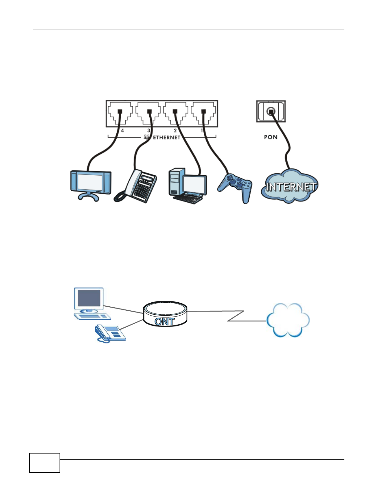
1.4.1 Triple Play
The ISP may provide “triple play” service to the GPON Device. This allows you to take advantage of
such features as broadband Internet access, Voice over IP telephony, and streaming video/audio
media, all at the same time with no noticeable loss in bandwidth.
Figure 1 Triple Play Example
1.4.2 Internet Access
Your GPON Device provides shared Internet access by connecting a fiber optic line provided by the
ISP to the PON port.
Figure 2 GPON Device’s Router Features
10
PMG5318-B20A User’s Guide
Page 11
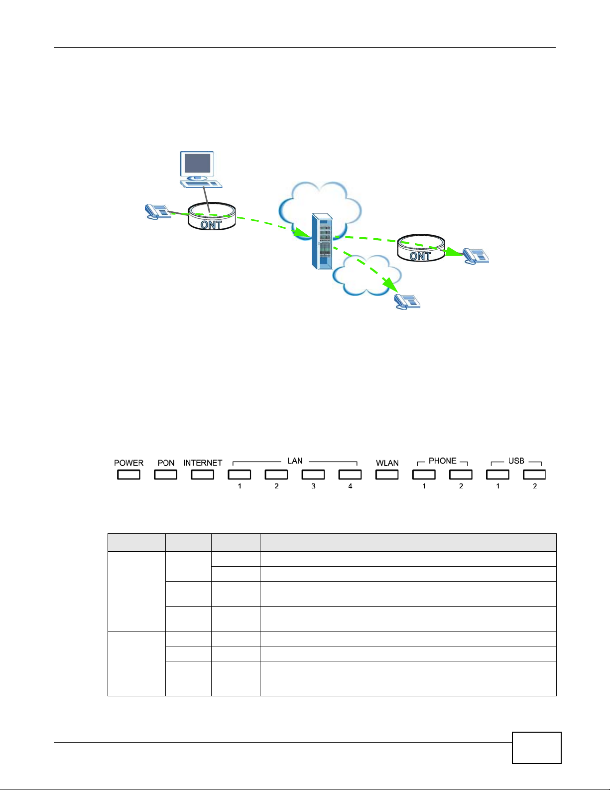
1.4.3 VoIP Features
Internet
PSTN
You can register up to 2 SIP (Session Initiation Protocol) accounts and use the GPON Device to
make and receive VoIP telephone calls:
Figure 3 GPON Device’s VoIP Features
Chapter 1 Introduction
Calls via a VoIP service provider - the GPON Device sends your call to a VoIP service provider’s SIP
server which forwards your calls to either VoIP or PSTN phones.
1.5 LEDs (Lights)
The following graphic displays the labels of the LEDs.
Figure 4 LEDs on the Top Panel
None of the LEDs are on if the GPON Device is not receiving power.
Table 1 LED Descriptions
LED COLOR STATUS DESCRIPTION
POWER Green On The GPON Device is receiving power and ready for use.
Red On The GPON Device detected an error while self-testing, or there is a
PON Green On The GPON Device has a PON line connection.
Orange On The GPON Device’s PON port is physically connected but not registered.
Red On The GPON Device’s PON port is not connected. The optical transceiver
Blinking The GPON Device is self-testing.
device malfunction.
Off The GPON Device is not receiving power and there is no device
malfunction.
may have malfunctioned or the fiber cable may not be connected or
may be broken or damaged enough to break the PON connection.
PMG5318-B20A User’s Guide
11
Page 12

Chapter 1 Introduction
Table 1 LED Descriptions
LED COLOR STATUS DESCRIPTION
INTERNET Green On The GPON Device has an IP connection but no traffic.
LAN 1~4 Green On The GPON Device has a 1G Ethernet connection with another device
WLAN Green On The wireless network is activated.
PHONE 1~2 Green On A SIP account is registered for the phone port.
USB 1~2 Green On The GPON Device recognizes a USB connection through the USB slot.
Blinking The GPON Device is sending or receiving IP traffic.
Off The GPON Device attempted to make an IP connection but failed.
Red On The GPON Device does not have an IP connection.
(such as a computer) on the Local Area Netwo rk (LAN) through this
port.
Blinking The GPON Device is sending/receiving data to/from the LAN th rough
Orange On The GPON Device has a 10/100M Ethernet connection with another
Blinking The GPON Device is sending/receiving data to/from the LAN th rough
Off The GPON Device does not have an Ethernet connection with the LAN
Blinking The GPON Device is communicating with other wireless clients.
Off The wireless network is not activated.
Orange Blinking The GPON Device is setting up a WPS connection.
Blinking A telephone connected to the phone port has its receiver off the hook or
Off The phone port does not have a SIP account registered.
Red On SIP account registration failed.
Blinking
Off The GPON Device does not detect a USB connection through the USB
this port.
device (such as a computer) on the Local Area Network (LAN) through
this port.
this port.
through this port.
there is an incoming call.
The GPON Device is sending or receiving data to or from the USB device
connected to it.
slot.
Refer to Section 1.5 on page 11 for information on hardware connections.
1.6 The Reset Button
If you forget your password or cannot access the web configurator, you will need to use the RESET
button at the back of the device to reload the factory-default configuration file. This means that y ou
will lose all configurations that you had previously and the password will be reset to the default.
1.6.1 Using the Reset Button
1 Make sure the POWER LED is on (not blinking).
12
PMG5318-B20A User’s Guide
Page 13
2 To set the device back to the factory default settings, press the RESET button for more than 3
seconds or until the POWER LED begins to blink and then release it. When the POWER LED begins
to blink, the defaults have been restored and the device restarts.
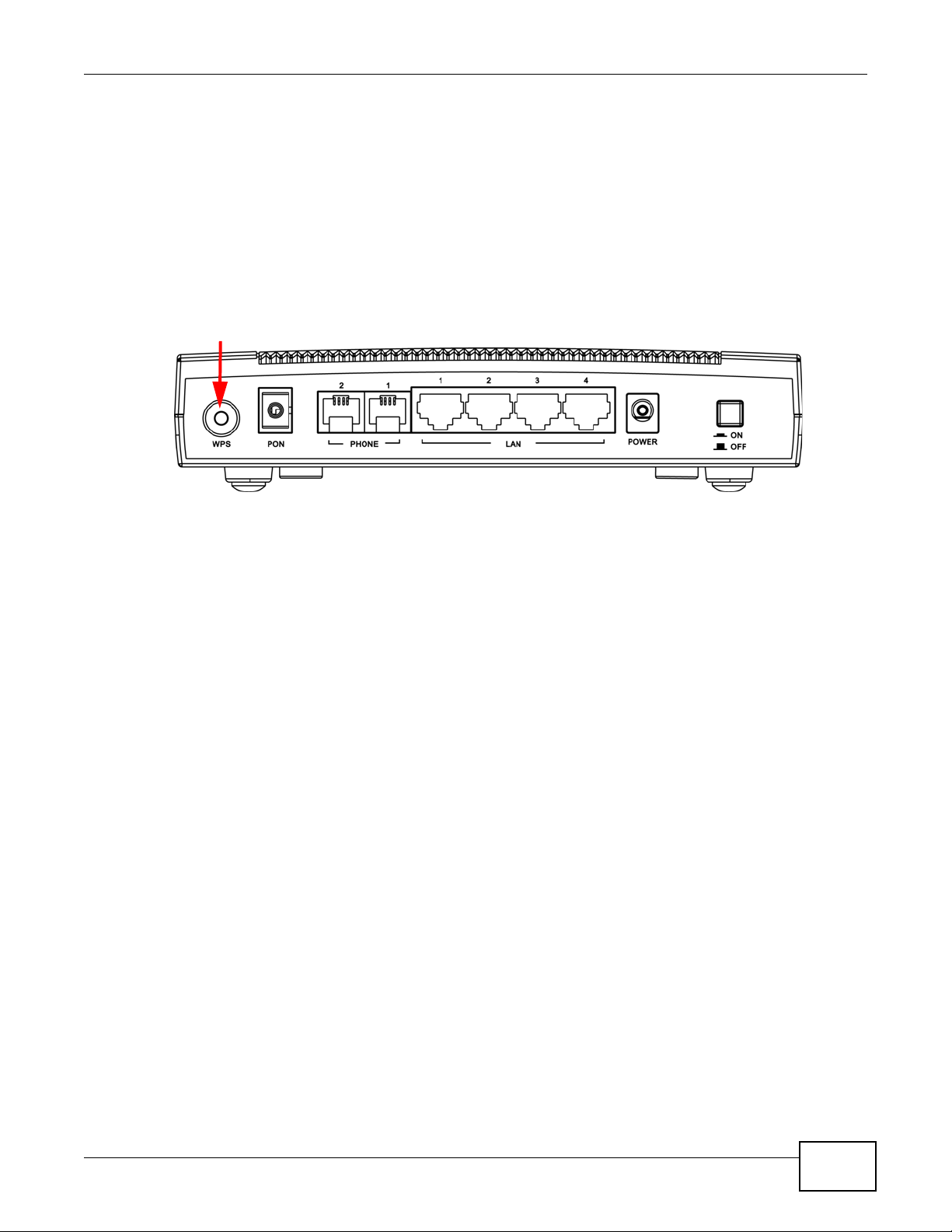
1.7 The WPS Button
You can use the WPS button on the back of the device to disable or activate the wireless LAN. You
can also use it to activate WPS in order to quickly set up a wireless network with strong security.
Figure 5 WPS Button
Chapter 1 Introduction
1.7.1 Using the WPS button
1 Make sure the POWER LED is on (not blinking).
2 If the wireless LAN of the GPON Device is enabled, the LED light shines green. If not, press the
WPS button for more than 5 seconds and release it when the LED turns green. If you want to turn
it off, press the WPS button for 5 seconds again.
3 Press the WPS button for over 5 seconds and release it. See above for WPS button location.
4 Press the WPS button on a compatible device within 2 minutes of pressing the button on the GPON
Device. The WLAN LED should flash in orange while the GPON Device sets up a WPS connection
with the other wireless device.
5 Once the connection is successfully made, the WLAN LED shines green.
PMG5318-B20A User’s Guide
13
Page 14

Chapter 1 Introduction
14
PMG5318-B20A User’s Guide
Page 15
2.1 Overview
The web configurator is an HTML-based management interface that allows easy device setup and
management via Internet browser. Use Internet Explorer 8.0 and later or Firefox 23.0.0 and later
versions. The recommended screen resolution is 1024 by 768 pixels.
In order to use the web configurator you need to allow:
• Web browser pop-up windows from your GPON Device. Web pop-up blocking is enabled by
default in Windows XP SP (Service Pack) 2.
• JavaScript (enabled by default).
• Java permissions (enabled by default).
CHAPTER 2
The Web Configurator
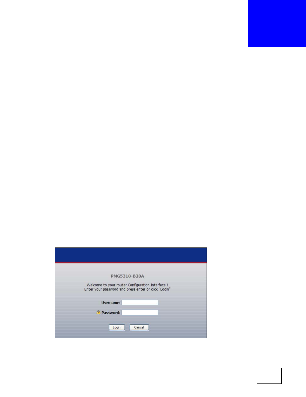
2.1.1 Accessing the Web Configurator
1 Make sure your GPON Device hardware is properly connected (refer to Section 1.5 on page 11 for
details on this).
2 Launch your web browser.
3 Type the default device address shown on the cover page of this User’s Guide as the URL.
4 A password screen displays. Enter your password and click Login.
Figure 6 Password Screen
Note: For security reasons, the GPON Device automatically logs you out if you do not use
the web configurator for an extended period of time. If this happens, log in again.
PMG5318-B20A User’s Guide 15
Page 16
Chapter 2 The Web Configurator
B
C
D
A
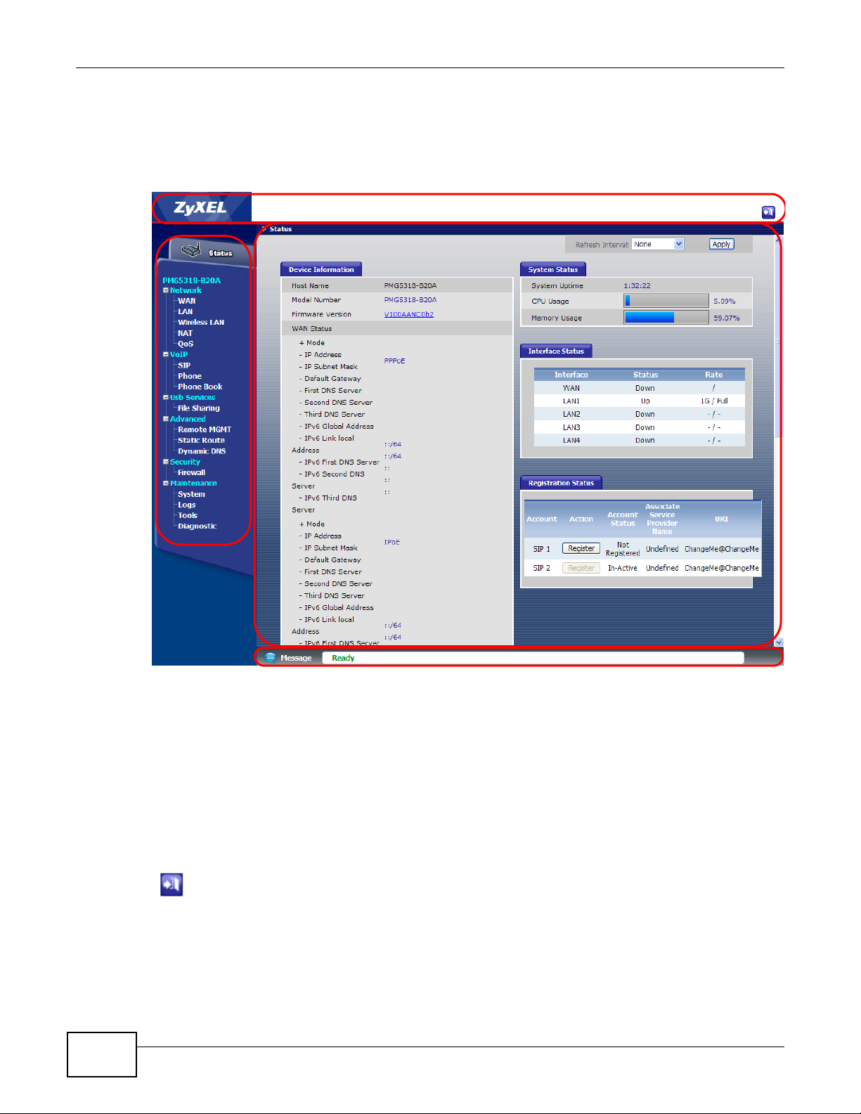
2.2 Web Configurator Main Screen
The main screen is divided into these parts:
Figure 7 Main Screen
• A - title bar
• B - navigation panel
• C - main window
• D - status bar
2.2.1 Title Bar
The title bar provides the Logout icon in the upper right corner. Click this icon to log out of the web
configurator
16
.
PMG5318-B20A User’s Guide
Page 17

2.2.2 Navigation Panel
Use the menu items on the navigation panel to open screens to configure GPON Device features.
The following tables describe each menu item.
Table 2 Navigation Panel Summary
LINK TAB FUNCTION
Status This screen shows the GPON Device’s general device and network
Network
WAN Internet Access
LAN
Wireless LAN
NAT Port Forwarding Use this screen to configure port forwarding rules.
QoS General Use this screen to enable and configure QoS settings for specific traffic.
VoIP
SIP SIP Service
Phone Analog Phone Use this screen to set which phone ports use which SIP accounts.
Phone Book Speed Dial Use this screen to configure speed dial for SIP phone numbers that you
Usb Services
File Sharing Share
Setup
Default
Gateway
Multicast Setup Use this screen to configure your ONT’s IGMP settings.
IP & DHCP Use this screen to configure LAN TCP/IP and DHCP settings, enable Any
Client List Use this screen to look at the IP addresses currently assigned to DHCP
Port Speed Use this screen to configure your ONT’s LAN port speed settings.
General Use this screen to turn the wireless connection on or off, configure the
Security Use this screen to set up wireless security.
WPS Use this screen to enable or disable WPS, generate a security PIN
WPS Station Use this screen to set up WPS by pressing a button or using a PIN.
MAC Filter Use this screen to allow or deny MAC address(es) for specific wireless
WMM Use this screen to enable Wi-Fi MultiMedia (WMM) to ensure quality of
Status Use this screen to view all accociated wireless clients and their status.
Isolation Use this screen to control whether associated wireless clients can
Provider
SIP Account Use this screen to configure your SIP account information.
Configuration
Account
Management
Chapter 2 The Web Configurator
status information. Use this screen to access the statistics and client
list.
Use this screen to configure ISP parameters, WAN IP address
assignment, DNS servers and other advanced properties.
Use this screen to configure your ONT’s default gateway settings.
IP and other advanced properties.
clients and the IP addresses reserved for specific MAC addresses.
MAC filter, and make other basic configuration changes.
(Personal Identification Number) and see information about the ONT’s
WPS status.
networks.
service in wireless networks for multimedia applications.
communicate with each other across a different wireless network
through the GPON Device.
Use this screen to configure the SIP settings used by the GPON Device
when you place calls over the Internet.
call often.
Use this screen to enable file sharing via the GPON Device.
Use this screen to configure user accounts to access file shares.
PMG5318-B20A User’s Guide
17
Page 18

Chapter 2 The Web Configurator
Table 2 Navigation Panel Summary
LINK TAB FUNCTION
Advanced
Remote MGMT WWW Use this screen to configure through which interface(s) and from which
Static Route Use this screen to configure the required information for a static route.
Dynamic DNS Use this screen to enable DDNS and configure the DDNS settings on
Security
Firewall General Use this screen to enable firewall and set the default action that the
Maintenance
System General Use this screen to configure your device’s name, management
Logs View Log Use this screen to display your device’s logs.
Tools Firmware Use this screen to upload firmware to your device.
Diagnostic General Use this screen to test the connections to o ther devices.
IP address(es) users can use HTTP to manage the GPON Device.
Telnet Use this screen to configure through which interface(s) and from which
IP address(es) users can use Telnet to manage the GPON Device.
FTP Use this screen to configure through which interface(s) and from which
IP address(es) users can use FTP to access the GPON Device.
SSH Use this screen to configure Secure SHell (SSH) connections to the
GPON Device.
ICMP Use this screen to set which interfaces respond to PING requests.
UPnP Use this screen to configure UPnP connections to the GPON Device.
TR-069 Use this screen to configure your ONT to be managed by an ACS.
the ONT.
firewall takes on packets depending on packet direction.
Rules Use this screen to view the configured firewall rules and add, edit or
remove a firewall rule.
inactivity timeout and password.
Time Setting Use this screen to change your GPON Device’s time and date.
SLID Use this screen change your ONT’s Subscriber Location ID (SLID)
setting.
Log Settings Use this screen to select which logs and/or immediate alerts your
device is to record. You can also set it to e-mail the logs to you.
Configuration Use this screen to backup and restore your device’s configuration
(settings) or reset the factory default settings.
Restart This screen allows you to reboot the GPON Device without turning the
power off.
2.2.3 Main Window
The main window displays information and configuration fields. It is discussed in the rest of this
document.
Right after you log in, the Status screen is displayed. See Chapter 3 on page 21 for more
information about the Status screen.
18
PMG5318-B20A User’s Guide
Page 19

2.2.4 Status Bar
Check the status bar when you click Apply or OK to verify that the configuration has been updated.
Chapter 2 The Web Configurator
PMG5318-B20A User’s Guide
19
Page 20

Chapter 2 The Web Configurator
20
PMG5318-B20A User’s Guide
Page 21
3.1 Overview
Use the Status screens to look at the current status of the device, system resources, interfaces
(LAN and WAN), and SIP accounts. You can also register and unregister SIP accounts.
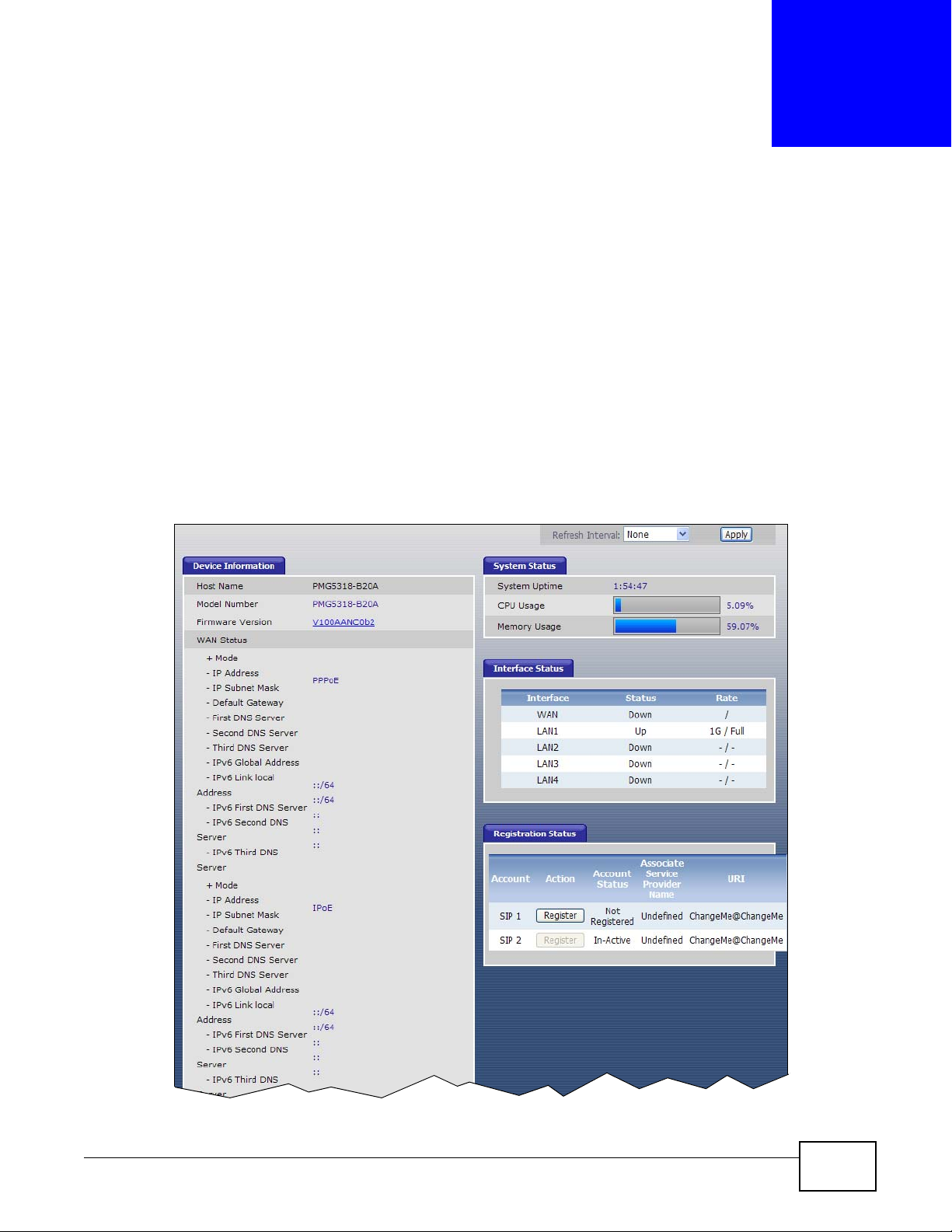
3.2 Status
Click Status to access this screen.
Figure 8 Status
CHAPTER 3
Status Screens
PMG5318-B20A User’s Guide 21
Page 22
Chapter 3 Status Screens
Each field is described in the following table.
Table 3 Status
LABEL DESCRIPTION
Device Information
Host Name This field displays the GPON Device system name. It is used for identification.
Model Name This is the model name of the GPON Device.
Firmware Version This field displays the current version of the firmware inside the device. It also
WAN Status This section displays connection information for each WAN connection configured
Mode This is the method of encapsulation used by your service provider for this WAN
IP Address This field displays the IP address of the WAN connection.
IP Subnet
Mask
Default
Gateway
First/Second/
Third DNS
Server
IPv6 Global
Address
IPv6 Link local
Address
IPv6 First/
Second/Third
DNS Server
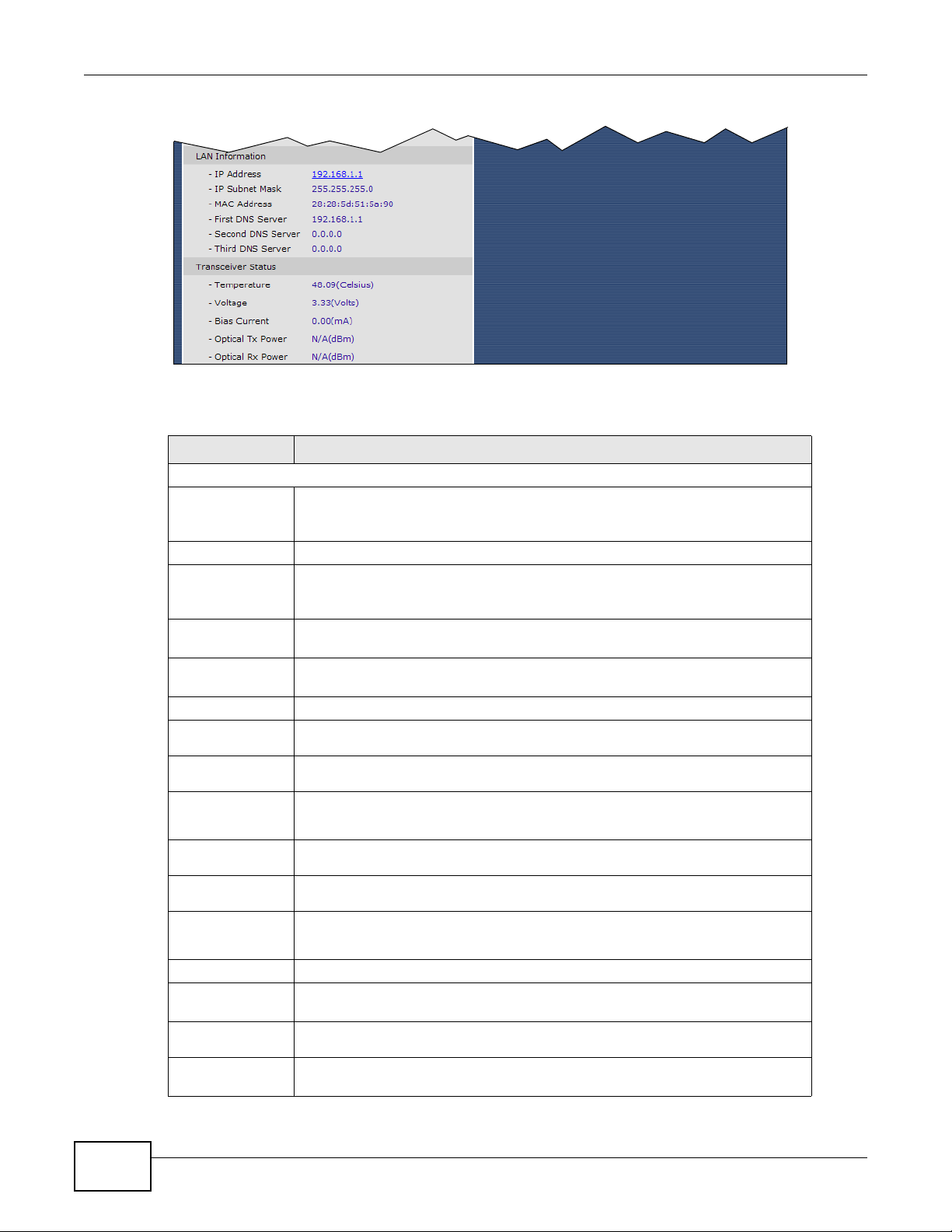
LAN Information
IP Address This field displays the current IP address of the GPON Device in the LAN. Click
IP Subnet
Mask
MAC Address This shows the LAN Ethernet adapter MAC (Media Access Control) address of
You can change this in the Maintenance > System > General screen’s
System Name field.
shows the date the firmware version was created. Click this to go to the screen
where you can change it.
on the GPON Device.
connection.
This field displays the WAN connection’s subnet mask.
This field displays the IP address of the default gateway, if applicable.
These are the DNS server IP addresses assigned to the WAN connection.
This is the IPv6 global address of the WAN connection.
This is the link-local address assigned to the WAN connection.
These are the IPv6 DNS server IP addresses assigned to the WAN connection.
this to go to the screen where you can change it.
This field displays the GPON Device’s current subnet mask in the LAN.
your GPON Device.
22
PMG5318-B20A User’s Guide
Page 23

Chapter 3 Status Screens
Table 3 Status
LABEL DESCRIPTION
First/Second/
Third DNS
Server
Transceiver
Status
Tempe rature This displays the temperature in Celsius. The normal range is 0-70 degrees.
Voltage This displays the voltage in Volts. The normal range is 3.13-3.47 Volts.
Bias Current This displays the bias current in mA. The normal range is 4-50 mA.
Optical Tx
Power
Optical Rx
Power
System Status
System Uptime This field displays how long the GPON Device has been running since it last
CPU Usage This field displays what percentage of the GPON Device’s processing ability is
Memory Usage This field displays what percentage of the GPON Device’s memory is currently
Interface Status
Interface This column identifies the interface on the GPON Device.
Status This field displays Up when the interface has a connection and Down when it
Rate This field displays the connection speed of the WAN interface’s PON connection
Registration Status
Account This column displays each SIP account in the GPON Device.
Action If the SIP accou nt is already register ed with the SIP serv er, the Account Status
These are the DNS server IP addresses the GPON Device passes to the DHCP
clients.
This displays the optical transmitting power in dBm.
This displays the optical receiving power in dBm. The normal range is -28 to -8
dBm.
started up. The GPON Device starts up when you plug it in, when you restart it
(Maintenance > Tools > Restart), or when you reset it.
currently used. When this percentage is close to 100%, the GPON Device is
running at full load, and the throughput is not going to improve anymore. If you
want some applications to have more throughput, you should turn off other
applications.
used. Usually, this percentage should not increase much. If memory usage does
get close to 100%, the GPON Device is probably becoming unstable, and you
should restart the device. See Section 18.4 on page 148, or turn it off (unplug
the power) for a few seconds.
does not.
when it is connected. This field displays the connection speed and duplex for a
connected LAN interface.
field displays Registered.
PMG5318-B20A User’s Guide
Click Unregister to delete the SIP account’s registration in the SIP server. This
does not cancel your SIP account, but it deletes the mapping between your SIP
identity and your IP address or domain name.
If the SIP account is not registered with the SIP server , the Account Status field
displays Not Registered.
Click Register to have the GPON Device attempt to register the SIP account
with the SIP server.
The button is grayed out if the SIP account is disabled.
23
Page 24

Chapter 3 Status Screens
Table 3 Status
LABEL DESCRIPTION
Account Status This field displays the current registration status of the SIP account. You have to
Associate Service
Provider Name
URI This field displays the account number and service domain of the SIP account.
register SIP accounts with a SIP server to use VoIP.
Inactive - The SIP account is not active. You can activate it in VoIP > SIP >
SIP Account.
Not Registered - The last time the GPON Device tried to register the SIP
account with the SIP server, the attempt failed. Use the Register button to
register the account again. The GPON Device automatically tries to register the
SIP account when you turn on the GPON Device or when you activate it.
Registered - The SIP account is already register ed with the SIP s er ver. You can
use it to make a VoIP call.
This column displays the service provider name for each SIP account.
You can change these in VoIP > SIP > SIP Settings.
24
PMG5318-B20A User’s Guide
Page 25

4.1 Overview
This chapter describes how to configure WAN settings. A WAN (Wide Area Network) is an outside
connection to another network or the Internet.
4.1.1 What You Need to Know
The following terms and concepts may help as you read through the chapter.
Encapsulation
Be sure to use the encapsulation method required by the ISP. The GPON Device supports the
following methods.
CHAPTER 4
WAN
PPP over Ethernet
The GPON Device supports PPPoE (Point-to-Point Protocol over Ethernet). PPPoE is an IETF Draft
standard (RFC 2516) specifying how a personal computer (PC) interacts with a broadband modem
(DSL, cable, wireless, etc.) connection. The PPPoE option is for a dial-up connection using PPPoE.
For the service provider, PPPoE offers an access and authentication method that works with existing
access control systems (for example RADIUS).
One of the benefits of PPPoE is the ability to let you access one of multiple network services, a
function known as dynamic service selection. This enables the service provider to easily create and
offer new IP services for individuals.
Operationally, PPPoE saves significant effort for both you and the ISP or carrier, as it requires no
specific configuration of the broadband modem at the customer site.
By implementing PPPoE directly on the GPON Device (rather than individual computers), the
computers on the LAN do not need PPPoE software installed, since the GPON Device does that part
of the task.
IP Address Assignment
A static IP is a fixed IP that the ISP provides. A dynamic IP is not fixed; the ISP assigns a different
one each time. The Single User Account feature can be enabled or disabled if you have either a
dynamic or static IP. However the encapsulation method assigned influences your choices for IP
address and ENET ENCAP gateway.
PMG5318-B20A User’s Guide 25
Page 26
Chapter 4 WAN
Multicast and IGMP
Traditionally, IP packets are transmitted in one of either two w ays - Unicast (1 sender - 1 recipient)
or Broadcast (1 sender - everybody on the network). Multicast delivers IP packets to a group of
hosts on the network - not everybody and not just 1.
IGMP (Internet Group Management Protocol) is a network-layer protocol used to establish
membership in a Multicast group - it is not used to carry user data.
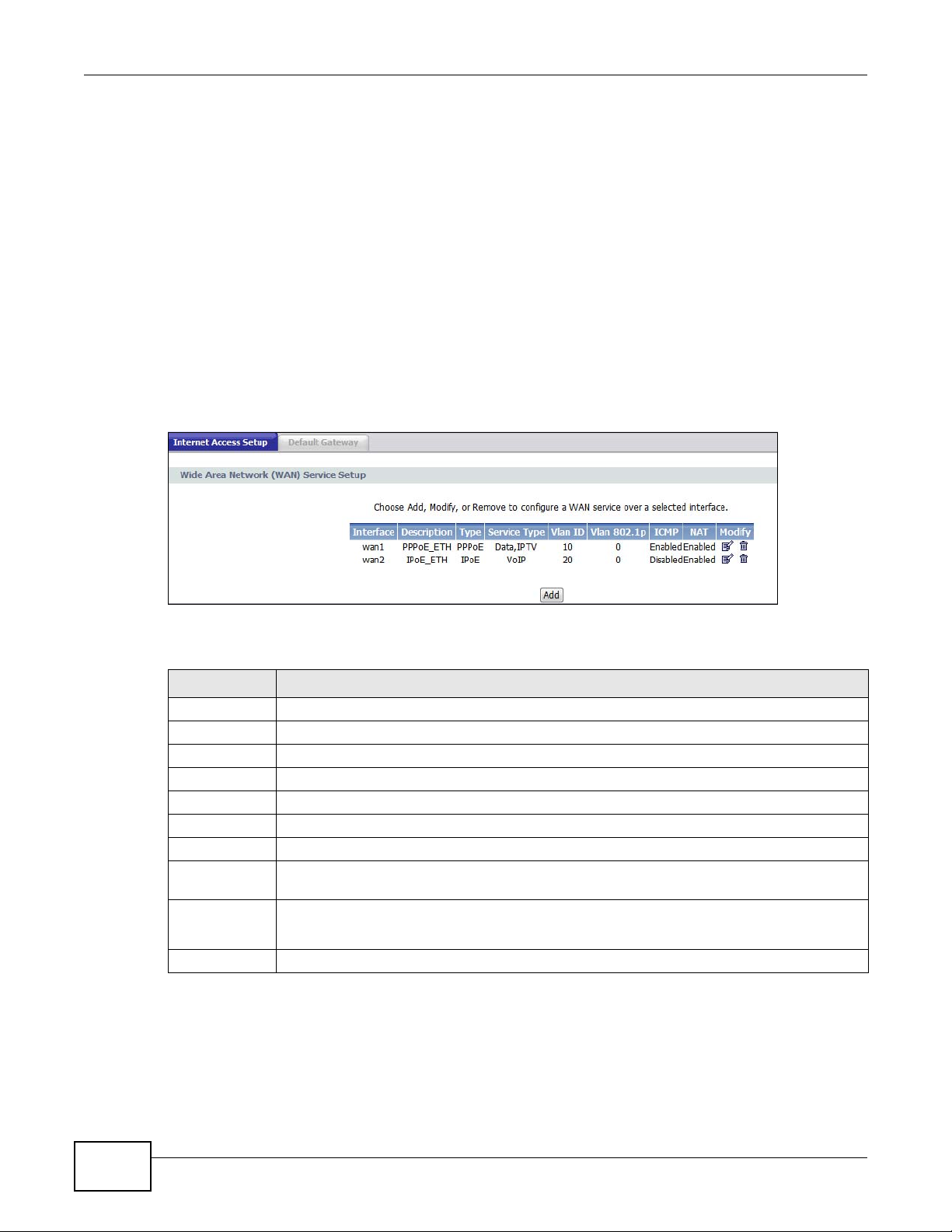
4.2 Internet Access Setup Status
Use this screen to view your GPON Device’s WAN settings. Click Network > WAN. Your GPON
Device’s number and names of default WAN interfaces may vary from this example.
Figure 9 Internet Access Setup Status
The following table describes the labels in this screen.
Table 4 Internet Access Setup Status
LABEL DESCRIPTION
Interface This shows the name of the interface used by this connection.
Description This is the service description for traffic using this connection.
Type This shows the method of encapsulation used by this connection.
Service Type This is the service type for traffic using this connection.
Vlan ID This shows the VLAN ID assigned to traffic for this connection. This is assigned by th e OLT.
Vlan 802.1p This displays the 802.1P priority level assigned to traffic sent through this connection.
ICMP This shows whether the WAN interface will respond to ICMP packets.
NAT This shows whether NAT is activated or not for this interface. NAT is not available when the
Modify Click the Edit icon to configure the WAN connection.
Add Click this to create a new WAN connection.
connection uses the bridging service.
Click the Remove icon to delete the WAN connection.
4.3 Internet Access Setup
26
Use these screens to configure your GPON Device’s WAN interfaces. Click Modify or Add in the
Network > WAN > Internet Access Setup status screen.
PMG5318-B20A User’s Guide
Page 27
The available fields vary in this screen depending on the option (PPPoE, IP, or Bridging) you
select in the WAN interface type field.
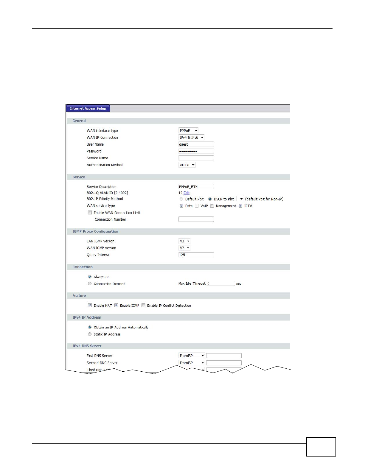
4.3.1 WAN Interface Type - PPPoE
Select PPPoE as the WAN interface type to open the following screen.
Figure 10 Internet Access Setup - PPPoE
Chapter 4 WAN
PMG5318-B20A User’s Guide
27
Page 28
Chapter 4 WAN
The following table describes the labels in this screen.
Table 5 Internet Access Setup - PPPoE
LABEL DESCRIPTION
General
WAN interface type Select PPPoE as the method of encapsulation used by your ISP from the drop-down
list box.
WAN IP Connection Select IPv4 to have this WAN run IPv4 only.
Select IPv6/IPv4 to allow this WAN to run IPv4 and IPv6 at the same time.
Select IPv6 to have this WAN run IPv6 only.
User Name Enter the user name exactly as assigned by the ISP. If assigned a name in the form
user@domain where domain identifies a service name, then enter both components
exactly as given.
Password Enter the password associated with the user name above.
Service Name Type the name of your PPPoE service here.
Authentication
Method
Service
Service Description Enter a description to identify this WAN interface.
The GPON Device supports PAP (Password Authentication Protocol) and CHAP
(Challenge Handshake Authentication Protocol). CHAP is more secure than PAP;
however, PAP is readily available on more platforms.
Use the drop-down list box to select an authentication protocol for outgoing calls.
Options are:
AUTO - Your GPON Device accepts either CHAP or PAP when requested by this remote
node.
CHAP - Your GPON Device accepts CHAP only.
PAP - Your GPON Device accepts PAP only.
28
PMG5318-B20A User’s Guide
Page 29

Chapter 4 WAN
Table 5 Internet Access Setup - PPPoE (continued)
LABEL DESCRIPTION
802.1Q VLAN ID This shows the VLAN ID assigned to traffic for this connection. Click Edit to open a
screen where you can select a different VLAN ID. See Section 4.3.4 on page 37 for
information on this screen.
802.1P Priority
Method
WAN service type If you select PPPoE or IP in the WAN service type field abov e, sele ct wh ich t ype of
Enable WAN
Connection Limit
Connection Number If you select Enable WAN Connection Limit, you can specify the maximum number
IGMP Proxy
Configuration
LAN IGMP version Select the IGMP version to be used for IGMP messages originating from the LAN.
WAN IGMP version Select the IGMP version to be used for IGMP messages originating from the WAN.
Query Interval Enter the time period in seconds between general queries. A general query is a
Connection
Always-on Select Always-on when you want your connection up all the time. The GPON Device
Connect Demand Select Connect Demand when you don't want the connection up all the time and
Feature
Enable NAT Select this check box to activate NAT on this connection.
Enable ICMP Internet Control Message Protocol is a message control and error-reporting protocol
Enable IP Conflict
Detection
IPv4 IP Address
Obtain an IP Address
Automatically
Select the 802.1P priority method to be assigned to traffic sent through this
connection.
traffic (Data, VoIP, Management, and/or IPTV) can use this WAN interface.
This field displays Bridge if you select Bridge in the WAN service type field above.
Select Enable WAN Connection Limit to limit the number of connections for a
service type.
of connections. For a low priority service type, you can set this number to a lower
value.
message sent to learn the multicast reception state of the device attached to the
interface.
will try to bring up the connection automatically if it is disconnected.
specify an idle time-out in the Max Idle Timeout field.
between a host server and a gateway to the Internet. ICMP uses Internet Protocol
(IP) datagrams, but the messages are processed by the TCP/IP software and directly
apparent to the application user.
Select this check box to reply to incoming WAN Ping requests. If this is not enabled,
the GPON Device will not respond to any incoming Ping requests.
Select this to have the GPON Device detect if the IP address assigned to this WAN
interface conflicts with other WAN IP addresses.
A dynamic IP address is not fixed; the ISP assigns a different one each time you
connect to the Internet.
Static IP Address A static IP address is a fixed IP that the ISP provides.
IPv4 DNS Server
PMG5318-B20A User’s Guide
Select Obtain an IP Address Automatically to get a dynamic IPv4 address for this
WAN.
Select Static IP Address and type the ISP assigned information in the field below.
29
Page 30

Chapter 4 WAN
Table 5 Internet Access Setup - PPPoE (continued)
LABEL DESCRIPTION
First DNS Server
Second DNS Server
Third DNS Server
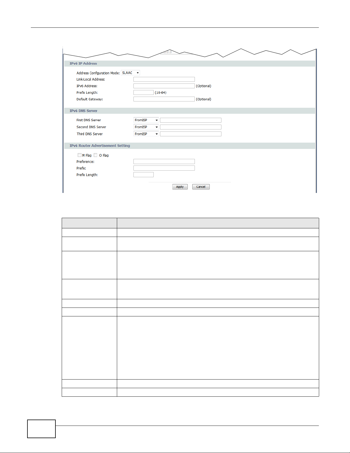
IPv6 IP Address
Address Configuration
Mode
Link-Local Address This field displays the link-local address the GPON Device generated itself for the
IPv6 Address Enter the IPv6 address assigned by your ISP for this WAN.
Prefix Length Enter the address prefix length to specify how many most significant bits in an IPv6
Default Gateway Enter the IP address of the next-hop gateway. The gateway is a router or switch on
IPv6 DNS Server
First DNS Server
Second DNS Server
Third DNS Server
IPv6 Router
Advertisement
Setting
M Flag
O Flag
Select From ISP if the ISP dynamically assigns DNS server information (and the
GPON Device's WAN IP address) and you select Obtain an IP Address
Automatically.
Select UserDefined if you have the IP address of a DNS server. Enter the DNS
server's IP address in the field to the right.
Select None if you do not want to configure DNS servers. You must have another
DNS server on your LAN, or else the computers must have their DNS server
addresses manually configured. If you do not configure a DNS server, you must know
the IP address of a computer in order to access it.
Select DHCP if you want to obtain an IPv6 address from a DHCPv6 server.
The IP address assigned by a DHCPv6 server has priority over the IP address
automatically generated by the Device using the IPv6 prefix from an RA.
Select SLAAC (Stateless address autoconfigu ration) to have the Device use the prefix
to automatically generate a unique IP address that does not need to be maintained by
a DHCP server.
Select Auto to have the Device indicate to hosts for IPv6 address generation
depending on the M/O (Managed/Other) flag values in the router advertisements
sending to hosts. You can configure the M/O flag settings in the IPv6 Router
Advertisement Setting section below.
WAN.
address compose the network address.
the same segment as your GPON Device's interface(s). The gateway helps forward
packets to their destinations.
Select From ISP if the ISP dynamically assigns DNS server information (and the
GPON Device's WAN IP address) and you select Obtain an IP Address
Automatically.
Select UserDefined if you have the IP address of a DNS server. Enter the DNS
server's IP address in the field to the right.
Select None if you do not want to configure DNS servers. You must have another
DNS server on your LAN, or else the computers must have their DNS server
addresses manually configured. If you do not configure a DNS server, you must know
the IP address of a computer in order to access it.
Select this option if you want to have the GPON Device use the IPv6 prefix from the
connected router’s Router Advertisement (RA) to generate an IPv6 address.
Select this to have the GPON Devi ce indicate to hosts to obtain network settings (such
as WAN IP, LAN prefix and DNS settings) through DHCPv6.
Clear this to have the GPON Device check O flag.
Select this to have the GPON Device indicate to hosts to obtain DNS information and
LAN prefix through DHCPv6.
Clear this to have the GPON Device not get information through DHCPv6.
30
PMG5318-B20A User’s Guide
Page 31

Chapter 4 WAN
Table 5 Internet Access Setup - PPPoE (continued)
LABEL DESCRIPTION
Preference This field displays the router preference (Low, Medium or High) the gateway
assigned to the GPON Device. The GPON Device sends this preference in the router
advertisements to tell hosts what preference they should use for the GPON Device.
This helps hosts to choose their default router es pecially when there are mu ltiple IPv6
routers in the network.
Note: Make sure the hosts also support router preference to make this function work.
Prefix Enter the IPv6 prefix provided by your ISP.
Prefix Length Enter the bit number of the IPv6 subnet mask provided by your ISP.
Apply Click Apply to save the changes.
Cancel Click Cancel to begin configuring this screen afresh.
PMG5318-B20A User’s Guide
31
Page 32

Chapter 4 WAN
4.3.2 WAN Interface Type - IP
Select IP as the WAN interface type to open the following screen.
Figure 11 Internet Access Setup - IP
32
PMG5318-B20A User’s Guide
Page 33

Chapter 4 WAN
The following table describes the labels in this screen.
Table 6 Internet Access Setup - IP
LABEL DESCRIPTION
General
WAN interface type Select IP as the method of encapsulation used by your ISP from the drop-down list
box.
WAN IP Connection Select IPv4 to have this WAN run IPv4 only.
Select IPv6/IPv4 to allow this WAN to run IPv4 and IPv6 at the same time.
Select IPv6 to have this WAN run IPv6 only.
ARP Ping
Enable ARP Ping Select this to have the GPON Device send ARP requests to the gateway regularly if the
gateway IP might change often. If the GPON Device does not receive the gateway’s
response, the GPON Device requests a new gateway IP through DHCP.
Service
Service Description Enter a description to identify this WAN interface.
802.1Q VLAN ID This shows the VLAN ID assigned to traffic for this connection. Click Edit to open a
screen where you can select a different VLAN ID. See Section 4.3.4 on page 37 for
information on this screen.
802.1P Priority
Method
Select the 802.1P priority method to be assigned to traffic sent through this
connection.
PMG5318-B20A User’s Guide
33
Page 34

Chapter 4 WAN
Table 6 Internet Access Setup - IP (continued)
LABEL DESCRIPTION
WAN service type Select which type of traffic (Data, VoIP, Management, and/or IPTV) can use this
WAN interface.
Enable WAN
Connection Limit
Connection Number If you select Enable WAN Connection Limit, you can specify the maximum number
IGMP Proxy
Configuration
LAN IGMP version Select the IGMP version to be used for IGMP messages originating from the LAN.
WAN IGMP version Select the IGMP version to be used for IGMP messages originating from the WAN.
Query Interval Enter the time period in seconds between general queries. A general query is a
Feature
Enable NAT Select this check box to activate NAT on this connection.
Enable ICMP Internet Control Message Protocol is a message control and error-reporting protocol
Select Enable WAN Connection Limit to limit the number of connections for a
service type.
of connections. For a low priority service type, you can set this number to a lower
value.
message sent to learn the multicast reception state of the device attached to the
interface.
between a host server and a gateway to the Internet. ICMP uses Internet Protocol
(IP) datagrams, but the messages are processed by the TCP/IP software and directly
apparent to the application user.
Select this check box to reply to incoming WAN Ping requests. If this is not enabled,
the GPON Device will not respond to any incoming Ping requests.
Enable IP Conflict
Detection
IPv4 IP Address
Obtain an IP Address
Automatically
Enable DHCP Option 60Select this to identify the vendor and functionality of the GPON Device in DHCP
Vendor Class
Identifier
Enable DHCP Option 61Select this to identify the GPON Device in DHCP requests that the GPON Device sends
Client Identifier If Hexadecimal is selecte d, you can e nter the GPON De vice’ s hardwa re address, that
Enable DHCP Option
125
Static IP Address A static IP address is a fixed IP that the ISP provides.
IPv4 DNS Server
Select this to have the GPON Device detect if the IP address assigned to this WAN
interface conflicts with other WAN IP addresses.
A dynamic IP address is not fixed; the ISP assigns a different one each time you
connect to the Internet.
Select Obtain an IP Address Automatically to get a dynamic IPv4 address for this
WAN.
The following DHCP Option 60, 61, and 125 fields are available only when you select
IP in the WAN interface type field above.
requests that the GPON Device sends to a DHCP server when getting a WAN IP
address.
Enter the Vendor Class Identifier (Option 60), such as the type of the hardware or
firmware.
to a DHCP server when getting a WAN IP address.
is the MAC address in this field using hexadecimal characters.
If String is selected, enter a string to identify the GPON Device using alphanumeric
characters.
Select this to add vendor specific information to DHCP requests th at the GPON Device
sends to a DHCP server when getting a WAN IP address.
Select Static IP Address and type the ISP assigned information in the field below.
34
PMG5318-B20A User’s Guide
Page 35

Chapter 4 WAN
Table 6 Internet Access Setup - IP (continued)
LABEL DESCRIPTION
First DNS Server
Second DNS Server
Third DNS Server
IPv6 IP Address
Address Configuration
Mode
Link-Local Address This field displays the link-local address the GPON Device generated itself for the
IPv6 Address Enter the IPv6 address assigned by your ISP for this WAN.
Prefix Length Enter the address prefix length to specify how many most significant bits in an IPv6
Default Gateway Enter the IP address of the next-hop gateway. The gateway is a router or switch on
IPv6 DNS Server
First DNS Server
Second DNS Server
Third DNS Server
IPv6 Router
Advertisement
Setting
M Flag
O Flag
Select From ISP if the ISP dynamically assigns DNS server information (and the
GPON Device's WAN IP address) and you select Obtain an IP Address
Automatically.
Select UserDefined if you have the IP address of a DNS server. Enter the DNS
server's IP address in the field to the right.
Select None if you do not want to configure DNS servers. You must have another
DNS server on your LAN, or else the computers must have their DNS server
addresses manually configured. If you do not configure a DNS server, you must know
the IP address of a computer in order to access it.
Select DHCP if you want to obtain an IPv6 address from a DHCPv6 server.
The IP address assigned by a DHCPv6 server has priority over the IP address
automatically generated by the Device using the IPv6 prefix from an RA.
Select SLAAC (Stateless address autoconfigu ration) to have the Device use the prefix
to automatically generate a unique IP address that does not need to be maintained by
a DHCP server.
Select Auto to have the Device indicate to hosts for IPv6 address generation
depending on the M/O (Managed/Other) flag values in the router advertisements
sending to hosts. You can configure the M/O flag settings in the IPv6 Router
Advertisement Setting section below.
WAN.
address compose the network address.
the same segment as your GPON Device's interface(s). The gateway helps forward
packets to their destinations.
Select From ISP if the ISP dynamically assigns DNS server information (and the
GPON Device's WAN IP address) and you select Obtain an IP Address
Automatically.
Select UserDefined if you have the IP address of a DNS server. Enter the DNS
server's IP address in the field to the right.
Select None if you do not want to configure DNS servers. You must have another
DNS server on your LAN, or else the computers must have their DNS server
addresses manually configured. If you do not configure a DNS server, you must know
the IP address of a computer in order to access it.
Select this option if you want to have the GPON Device use the IPv6 prefix from the
connected router’s Router Advertisement (RA) to generate an IPv6 address.
Select this to have the GPON Devi ce indicate to hosts to obtain network settings (such
as WAN IP, LAN prefix and DNS settings) through DHCPv6.
Clear this to have the GPON Device check O flag.
Select this to have the GPON Device indicate to hosts to obtain DNS information and
LAN prefix through DHCPv6.
Clear this to have the GPON Device not get information through DHCPv6.
PMG5318-B20A User’s Guide
35
Page 36

Chapter 4 WAN
Table 6 Internet Access Setup - IP (continued)
LABEL DESCRIPTION
Preference This field displays the router preference (Low, Medium or High) the gateway
assigned to the GPON Device. The GPON Device sends this preference in the router
advertisements to tell hosts what preference they should use for the GPON Device.
This helps hosts to choose their default router es pecially when there are mu ltiple IPv6
routers in the network.
Note: Make sure the hosts also support router preference to make this function work.
Prefix Enter the IPv6 prefix provided by your ISP.
Prefix Length Enter the bit number of the IPv6 subnet mask provided by your ISP.
Apply Click Apply to save the changes.
Cancel Click Cancel to begin configuring this screen afresh.
4.3.3 WAN Interface Type - Bridging
Select Bridging as the WAN interface type to open the following screen.
Figure 12 Internet Access Setup - Bridging
36
The following table describes the labels in this screen.
Table 7 Internet Access Setup - Bridging
LABEL DESCRIPTION
General
WAN interface type Select Bridging as the method of encapsulation used by your ISP from the drop-
down list box.
Bridging LAN ports Select one or more LAN or wireless port(s) to bind with this WAN connection. Only the
Service
Service Description Enter a description to identify this WAN interface.
802.1Q VLAN ID This shows the VLAN ID assigned to traffic for this connection. Click Edit to open a
802.1P Priority
Method
WAN service type This field displays Bridge.
selected ports here can use this WAN connection.
screen where you can select a different VLAN ID. See Section 4.3.4 on page 37 for
information on this screen.
Select the 802.1P priority method to be assigned to traffic sent through this
connection.
PMG5318-B20A User’s Guide
Page 37

Table 7 Internet Access Setup - Bridging (continued)
LABEL DESCRIPTION
Apply Click Apply to save the changes.
Cancel Click Cancel to begin configuring this screen afresh.
4.3.4 802.1Q VLAN ID - Edit
Use this screen to configure the 802.1Q VLAN ID settings for a WAN interface. Click Edit next to
802.1Q VLAN ID on an Internet Access Setup screen.
Figure 13 802.1Q VLAN ID - Edit
Chapter 4 WAN
The following table describes the labels in this screen.
Table 8 802.1Q VLAN ID - Edit
LABEL DESCRIPTION
Provisioned VLAN/
Pbit
Status This column displays the current status of the respective VLAN/Pbit. It will display if it
Apply Click Apply to save the changes.
The available VLAN/Pbit values provisioned by the OLT are listed in this column. You
can select a VLAN/Pbit to be used by this WAN interface.
is in use by a WAN interface, or not in use.
PMG5318-B20A User’s Guide
37
Page 38

Chapter 4 WAN
4.4 Default Gateway
Use this screen to configure your GPON Device’s default gateway settings. Click Network > WAN
> Default Gateway.
Figure 14 Default Gateway
The following table describes the labels in this screen.
Table 9 Default Gateway
LABEL DESCRIPTION
WAN Interface Select a WAN interface you want to act as the default gateway.
WAN Status This displays if the interface displayed in the WAN Interface column is Up or Down.
Apply Click Apply to save the changes.
Cancel Click this to restore your previously saved settin gs.
38
PMG5318-B20A User’s Guide
Page 39

5.1 Overview
Internet
LAN
WAN
A
This chapter describes how to configure LAN settings.
A Local Area Network (LAN) is a shared communication system to which many computers are
attached. A LAN is a computer network limited to the immediate area, usually the same building or
floor of a building. The LAN screens can help you configure a LAN DHCP server and manage IP
addresses.
5.1.1 What You Need to Know
The following terms and concepts may help as you read through this chapter.
CHAPTER 5
LAN
LANs, WANs and the GPON Device
The actual physical connection determines whether the GPON Device ports are LAN or WAN ports.
There are two separate IP networks, one inside the LAN network and the other outside the WAN
network as shown next. The figure shows the GPON Device A.
Figure 15 LAN and WAN IP Addresses
PMG5318-B20A User’s Guide 39
Page 40

Chapter 5 LAN
5.2 The IP and DHCP Screen
Click Network > LAN to open the IP & DHCP screen. Use this screen to set the Local Area
Network IP address and subnet mask of your GPON Device.
Figure 16 LAN & DHCP
40
The following table describes the fields in this screen.
Table 10 IP & DHCP
LABEL DESCRIPTION
LAN TCP/IP
IP Address Enter the LAN IP address you want to assign to your GPON Device in dotted decimal
notation, for example, 192.168.1.1 (factory default).
IP Subnet Mask Type the subnet mask of your network in dotted decimal notation, for example
DHCP Setup
DHCP Select whether to have the GPON Device act as a DHCP Server.
IP Pool Starting
Address
255.255.255.0 (factory default). Your GPON Device automatically computes the
subnet mask based on the IP Address you enter, so do not change this field unless you
are instructed to do so.
Select Server to have the GPON Device assign IP addresses and provide subnet mask,
gateway, and DNS server information to the network. The GPON Device is the DHCP
server for the network.
Otherwise, select Disable to not have the GPON Device provide any DHCP services.
The DHCP server will be disabled.
This field specifies the first of the contiguous addresses in the IP address pool.
PMG5318-B20A User’s Guide
Page 41

Chapter 5 LAN
Table 10 IP & DHCP (continued)
LABEL DESCRIPTION
Pool Size This field specifies the size, or count of the IP address pool.
DHCP Lease Time This field specifies the lease time in seconds of the IP address assigned by the DHCP
server.
Enable DHCP
option 43
DNS Server
First DNS Server
Second DNS Server
Third DNS Server
Apply Click Apply to save your changes back to the GPON Device.
Cancel Click Cancel to begin configuring this screen afresh.
Select this and type the Vender specific information you want the GPON Device to
add in the DHCP Offer packets. The information is used, for example, for configuring
an ACS’s (Auto Configuration Server) URL.
Select FromISP if the ISP dynamically assigns DNS server information (and the GPON
Device's WAN IP address).
Select UserDefined if you have the IP address of a DNS server. Enter the DNS
server's IP address in the field to the right.
Select DNS Relay to have the GPON Device act as a DNS proxy only when the ISP
uses IPCP DNS server extensions. The GPON Device's LAN IP address displays in the
field to the right (read-only). The GPON Device tells the DHCP clients on the LAN that
the GPON Device itself is the DNS server. When a computer on the LAN sends a DNS
query to the GPON Device, the GPON Device forwards the query to the real DNS
server learned through IPCP and relays the response back to the computer.
Select None if you do not want to configure DNS servers. You must have another
DHCP sever on your LAN, or else the computers must have their DNS server addresses
manually configured. If you do not configure a DNS server, you must know the IP
address of a computer in order to access it.
5.3 Client List
Use this screen to look at the IP addresses currently assigned to DHCP clients and the IP addresses
reserved for specific MAC addresses. Click Network > LAN > Client List.
This table allows you to assign IP addresses on the LAN to specific individual computers based on
their MAC Addresses.
Every Ethernet device has a unique MAC (Media Access Control) address. The MAC address is
assigned at the factory and consists of six pairs of hexadecimal characters, for example,
00:A0:C5:00:00:02.
Figure 17 Client List
PMG5318-B20A User’s Guide
41
Page 42

Chapter 5 LAN
The following table describes the labels in this screen.
Tab le 11 Client List
LABEL DESCRIPTION
IP Address Enter the IP address that you want to assign to the computer on your LAN with the MAC
MAC Address Enter the MAC address of a computer on your LAN.
Add Click Add to add a static DHCP entry.
# This is the index number of the static IP table entry (row).
Status This field displays whether the client is connected to the GPON Device.
Host Name This field displays the computer host name.
Interface Type This field displays if the client is connected through ethernet or wireless.
IP Address This field displays the IP address relative to the # field listed above.
MAC Address The MAC (Media Access Control) or Ethernet address on a LAN (L ocal Area Network) is
Remaining Lease
Time
Reserve Select the check box in the heading row to automatically select all check boxes or
Apply Click Apply to save your changes back to the GPON Device.
Cancel Click Cancel to begin configuring this screen afresh.
Refresh Click Refresh to reload the DHCP table.
address that you will also specify.
unique to your computer (six pairs of hexadecimal notation).
A network interface card such as an Ethernet adapter has a hardwired address that is
assigned at the factory. This address follows an industry standard that ensures no other
adapter has a similar address.
This field displays the remaining time for this DHCP lease.
select the check box(es) in each entry to have the GPON Device always assign the
selected entry(ies)’s IP address(es) to the corresponding MAC address(es) (and host
name(s)). You can select up to 128 entries in this table.
5.4 Port Speed
Use this screen to configure your GPON Device’s LAN port speed settings. Click Network > LAN >
Port Speed.
Figure 18 Port Speed
42
PMG5318-B20A User’s Guide
Page 43

Chapter 5 LAN
The following table describes the labels in this screen.
Table 12 Port Speed
LABEL DESCRIPTION
LAN Port This column displays the LAN port number.
Speed Select Autonegotiation to have the GPON Device automatically use 1G, 100M or
Duplex Select Auto to have t he GPON Dev ice autom ati call y use full or half duplex depending
Apply Click Apply to save the changes.
Cancel Click this to restore your previously saved settin gs.
10M depending on the device connected to the port. Y ou can also ma nually select one
of these speeds.
on the device connected to the port. You can also manually select a Full or Half
duplex.
PMG5318-B20A User’s Guide
43
Page 44

Chapter 5 LAN
44
PMG5318-B20A User’s Guide
Page 45

6.1 Overview
This chapter describes how to perform tasks related to setting up and optimizing your wireless
network, including the following.
• Turning the wireless connection on or off.
• Configuring a name, wireless channel and security for the network.
• Using WiFi Protected Setup (WPS) to configure your wireless network.
• Setting up multiple wireless networks.
• Using a MAC (Media Access Control) address filter to restrict access to the wireless network.
• Performing other performance-related wireless tasks.
CHAPTER 6
Wireless LAN
6.1.1 What You Need to Know About Wireless
Wireless Basics
“Wireless” is essentially radio communication. In the same way that walkie-talkie radios send and
receive information over the airwaves, wireless networking devices exchange information with one
another. A wireless networking device is just like a radio that lets your computer exchange
information with radios attached to other computers. Like walkie-talkies, most wireless networking
devices operate at radio frequency bands that are open to the public and do not require a license to
use. However, wireless networking is different from that of most traditional radio communications in
that there a number of wireless networking standards available with different methods of data
encryption.
SSID
Each network must have a name, referred to as the SSID - “Service Set IDentifier”. The “service
set” is the network, so the “service set identifier” is the network’s name. This helps you identify
your wireless network when wireless networks’ coverage areas overlap and you have a variety of
networks to choose from.
MAC Address Filter
Every Ethernet device has a unique MAC (Media Access Control) address. The MAC address consists
of twelve hexadecimal characters (0-9, and A to F), and it is usually written in the following format:
“0A:A0:00:BB:CC:DD”.
The MAC address filter controls access to the wireless network. You can use the MAC address of
each wireless client to allow or deny access to the wireless network.
PMG5318-B20A User’s Guide 45
Page 46

Chapter 6 Wireless LAN
Finding Out More
See Section 6.9 on page 57 for advanced technical information on wireless networks.
6.1.2 Before You Start
Before you start using these screens, ask yourself the following questions. See Section 6.1.1 on
page 45 if some of the terms used here are not familiar to you.
• What wireless standards do the other wireless devices in your network support (IEEE 802.11g,
for example)? What is the most appropriate standard to use?
• What security options do the other wireless devices in your network support (WPA-PSK, for
example)? What is the strongest security option supported by all the devices in your network?
• Do the other wireless devices in your network support WPS (Wi-Fi Protected Setup)? If so, you
can set up a well-secured network very easily.
Even if some of your devices support WPS and some do not, you can use WPS to set up your
network and then add the non-WPS devices manually, although this is somewhat more
complicated to do.
• What advanced options do you want to configure, if any? If you want to configure advanced
options such as Quality of Service, ensure that you know precisely what you want to do. If you do
not want to configure advanced options, leave them as they are.
6.2 The General Screen
Use this screen to configure the wireless settings of your GPON Device. Click Network > Wireless
LAN to open the General screen.
Figure 19 Network > Wireless LAN > General
46
PMG5318-B20A User’s Guide
Page 47

Chapter 6 Wireless LAN
The following table describes the labels in this screen.
Table 13 Network > Wireless LAN > General
LABEL DESCRIPTION
Wireless Setup
Enable Wireless
LAN
Enable
MultiSSID
SSID The SSID (Service Set IDentity) identifies the service set with which a wireless device is
Click the check box to activate wireless LAN.
Select this to enable Multi SSID (Service Set IDentity) to have the have the GPON Device
broadcast several Basic Service Sets (BSSs) simultaneously.
associated. Wireless devices associating to the access point (AP) must have the same
SSID. Enter a descriptive name (up to 32 printable 7-bit ASCII characters) for the wireless
LAN.
Note: If you are configuring the GPON Device from a computer connected to the wireless
LAN and you change the GPON Device’s SSID or any wireless security settings, you
will lose your wireless connection when you press Apply to confirm. You must then
change the wireless settings of your computer to match the GPON Device’s new
settings.
Hide SSID Select this check box to hide the SSID in the outgoing beacon frame so a station cannot
obtain the SSID through scanning using a site survey tool.
Power Level
Channel
Selection
Wireless Advanced Setup
Click Advanced or Basic to display or hide this section.
802.11 Mode Select 802.11 B Only to allow only IEEE 802.11b compliant WLAN devices to associate
Select the wireless transmission power (High, Medium, Low) of the GPON Device . If
there is a high density of wireless APs in an area, decrease the power level to reduce
interference with other APs.
Set the operating channel manually by selecting a channel from the Channel Selection
list or use Auto Channel Select to have it automatically configured.
with the GPON Device.
Select 802.11 G Only to allow only IEEE 802.11g compliant WLAN devices to associate
with the GPON Device.
Select 802.11 N Only to allow only IEEE 802.11n compliant WLAN devices to associate
with the GPON Device.
Select 802.11 B/G to allow either IEEE 802.11b or IEEE 802.11g compliant WLAN devices
to associate with the GPON Device. The transmission rate of your GPON Device might be
reduced.
Select 802.11 B/G/N to allow IEEE 802.11b, IEEE 802.11g or IEEE802.11n compliant
WLAN devices to associate with the GPON Device. The transmission rate of your GPON
Device might be reduced.
Apply Click this to save your changes.
Cancel Click this to restore your previously saved settings.
6.3 The Security Screen
Use this screen to configure the wireless security settings of your GPON Device. Click Network >
Wireless LAN > Security to open the Security screen.
PMG5318-B20A User’s Guide
47
Page 48

Chapter 6 Wireless LAN
6.3.1 No Security
In the Network > Wireless LAN > Security screen, select No Security from the Security Mode
list to allow wireless devices to communicate with the GPON Device without any data encryption or
authentication.
Note: If you do n ot enable any wireless securi ty on your GPON D e vice, your network is
accessible to any wireless networking device that is within range.
Figure 20 Network > Wireless LAN > Security: No Security
The following table describes the labels in this screen.
Table 14 Network > Wireless LAN > Security: No Security
LABEL DESCRIPTION
SSID Select Select the SSID for which you are configuring security settings.
Security Mode Choose No Security from the drop-down list box.
6.3.2 WEP Encryption
Use this screen to configure and enable WEP encryption. Click Network > Wireless LAN >
Security to display the Security screen. Select Static WEP from the Security Mode list.
48
PMG5318-B20A User’s Guide
Page 49

Chapter 6 Wireless LAN
Note: WEP is extremely insecure. Its encryption can be broken by an attacker, using
widely-available software. It is strongly recommended that you use a more
effective security mechanism. Use the strongest security mechanism that all the
wireless devices in your network support. For ex ample, use WP A -PSK o r WP A2-PSK
if all your wireless devices support it. If your wireless devices support nothing
stronger than WEP, use the highest encryption level available.
Figure 21 Network > Wireless LAN > Security: Static WEP
The following table describes the wireless LAN security labels in this screen.
Table 15 Network > Wireless LAN > Security: Static WEP
LABEL DESCRIPTION
SSID Select Select the SSID for which you are configuring security settings.
Security Mode Choose Static WEP from the drop-down list box.
Passphrase Enter a passphrase (up to 32 printable characters) and click Generate. The GPON Device
WEP Key The WEP key is used to encrypt data. Both the GPON Device and the wireless stations must
automatically generates a WEP key.
use the same WEP key for data transmission.
If you want to manually set the WEP key, enter any 5 or 13 characters (ASCII string) or 10
or 26 hexadecimal characters ("0-9", "A-F") for a 64-bit or 128-bit WEP key respectively.
PMG5318-B20A User’s Guide
49
Page 50

Chapter 6 Wireless LAN
6.3.3 WPA(2)-PSK
Use this screen to configure and enable WPA(2)-PSK authentication. Click Network > Wireless
LAN > Security to display the Security screen. Select WPA-PSK or WPA2-PSK from the
Security Mode list.
Figure 22 Network > Wireless LAN > Security: WPA(2)-PSK
The following table describes the wireless LAN security labels in this screen.
Table 16 Network > Wireless LAN > Security: WPA(2)-PSK
LABEL DESCRIPTION
SSID Select Select the SSID for which you are configuring security settings.
Security Mode Choose WPA-PSK or WPA2-PSK from the drop-down list box.
WPA Compatible This check box is available only when you select WPA2-PSK in the Security Mode
field.
Select the check box to have both WPA-PSK wireless clients be able to communicate
with the GPON Device even when the GPON Device is using WPA2-PSK.
Pre-Shared Key The encryption mechanisms used for WPA(2) and WPA(2)-PSK are the same. The
only difference between the two is that WPA(2)-PSK uses a simple common
password, instead of user-specific credentials.
Type a pre-shared key from 8 to 63 case-sensitive ASCII char acters (i n cludi ng spac es
and symbols).
WPA Group Key
Update Timer
The Group Key Update Timer is the r ate at which the AP (i f using WPA(2)-PSK key
management) sends a new group key out to all clients. The re-keying process is the
WPA(2) equivalent of automatically changing the WEP key for an AP and all stations in
a WLAN on a periodic basis.
50
PMG5318-B20A User’s Guide
Page 51

6.3.4 WPA(2)
Use this screen to configure and enable WPA(2) authentication. Click Network > Wireless LAN >
Security to display the Security screen. Select WPA or WPA2 from the Security Mode list.
Figure 23 Network > Wireless LAN > Security: WPA(2)
Chapter 6 Wireless LAN
The following table describes the wireless LAN security labels in this screen.
Table 17 Network > Wireless LAN > Security: WPA(2)
LABEL DESCRIPTION
SSID Select Select the SSID for which you are configuring security settings.
Security Mode Choose WPA or WPA2 from the drop-down list box.
WPA Compatible This check box is available only when you select WPA2 in the Security Mode field.
Select the check box to have both WPA wireless clients be able to communicate with
the GPON Device even when the GPON Device is using WPA2.
Authentication Server
IP Address Enter the IP address of the external authentication server in dotted decimal notation.
Port Number Enter the port number of the external authentication server. The default port number
is 1812.
You need not change this value unless your network administrator instructs you to do
so with additional information.
Shared Secret Enter a password (up to 31 alphanumeric characters) as the key to be shared between
the external authentication server and the GPON Device.
The key must be the same on the external authentication server and your GPON
Device. The key is not sent over the network.
Group Key Update
Timer
The Group Key Update Timer is the rate at which the RADIUS server (if using
WPA(2) key management) sends a new group key out to all clients. The re-keying
process is the WPA(2) e quiva lent of automati cally changin g the WEP ke y for an AP and
all stations in a WLAN on a periodic basis. The GPON Device default is 1800 seconds
(30 minutes).
PMG5318-B20A User’s Guide
51
Page 52

Chapter 6 Wireless LAN
6.4 The WPS Screen
Use this screen to configure WiFi Protected Setup (WPS) on your GPON Device.
WPS allows you to quickly set up a wireless network with strong security, without having to
configure security settings manually. Set up each WPS connection between two devices. Both
devices must support WPS.
Click Network > Wireless LAN > WPS. The following screen displays.
Figure 24 Network > Wireless LAN > WPS
The following table describes the labels in this screen.
Table 18 Network > Wireless LAN > WPS
LABEL DESCRIPTION
WPS Setup
Enable WPS Select the check box to activate WPS on the GPON Device.
PIN Number The PIN of the GPON Device is shown here. Enter this PIN in the configuration utility of
the device you want to connect to using WPS.
The PIN is not necessary when you use WPS push-button method.
Click the Generate button to have the Device create a new PIN.
WPS Status This displays Configured when the GPON Device has connected to a wireless network
using WPS or Enable WPS is selected and wireless or wireless security settings have
been changed. The current wireless and wireless security settings also appear in the
screen.
This displays Unconfigured if WPS is disabled and there is no wireless or wireless
security changes on the GPON Device or you click Release to remove the configured
wireless and wireless security settings.
Release This button is available when the WPS status is Configured.
Click this button to remove all configured wireless and wireless security settings for WPS
connections on the GPON Device.
Apply Click this to save your changes.
Cancel Click this to restore your previously saved settings.
52
PMG5318-B20A User’s Guide
Page 53

6.5 The WPS Station Screen
Use this screen to set up a WPS wireless network using either Push Button Configuration (PBC) or
PIN Configuration.
Click Network > Wireless LAN > WPS Station. The following screen displays.
Figure 25 Network > Wireless LAN > WPS Station
The following table describes the labels in this screen.
Chapter 6 Wireless LAN
Table 19 Network > Wireless LAN > WPS Station
LABEL DESCRIPTION
Push Button Click this to add another WPS-enabled wireless device (within wireless range of the
Or input station's
PIN number
6.5.1 MAC Filter
Use this screen to change your GPON Device’s MAC filter settings.
GPON Device) to your wireless network. This button may either be a physical button on
the outside of device, or a menu button similar to the Push Button on this screen.
Note: You must press the other wireless device’s WPS button within two minutes of
pressing this button.
Enter the PIN of the device that you are setting up a WPS connection with and click Start
to authenticate and add the wireless device to your wireless network.
You can find the PIN either on the outside of the device, or by checking the device’s
settings.
Note: You must also activate WPS on that device within two minutes to have it present its
PIN to the GPON Device.
PMG5318-B20A User’s Guide
53
Page 54

Chapter 6 Wireless LAN
Click Network > Wireless LAN > MAC Filter. The following screen displays.
Figure 26 Network > Wireless LAN > MAC Filter
54
The following table describes the labels in this screen.
Table 20 Network > Wireless LAN > MAC Filter
LABEL DESCRIPTION
Filter Action
SSID Select Select the SSID for which you want to configure MAC filter settings.
Enable MAC
Filter
#
MAC Address Enter the MAC addresses of the wireless devices that are allowed access to the GPON Device
Define the MAC filter action for all SSIDs’ MAC addresses listed in the MAC Address table
below.
Select Deny to block access to the GPON Device. MAC addresses not listed can access the
GPON Device.
Select Allow to permit access to the GPON Device. MAC addresses not listed cannot access
to the GPON Device.
Select the check box to enable MAC address filtering for the selected SSID.
This is the index number of the MAC address.
in these address fields. Enter the MAC addresses in a valid MAC address format, that is, six
hexadecimal character pairs, for example, 12:34:56:78:9a:bc.
PMG5318-B20A User’s Guide
Page 55

Table 20 Network > Wireless LAN > MAC Filter
LABEL DESCRIPTION
Apply Click this to save your changes.
Cancel Click this to restore your previously saved settings.
6.6 The WMM Screen
Use this screen to enable or disable Wi-Fi MultiMedia (WMM) wireless networks for multimedia
applications.
Click Network > Wireless LAN > WMM. The following screen displays.
Figure 27 Network > Wireless LAN > WMM
Chapter 6 Wireless LAN
The following table describes the labels in this screen.
Table 21 Network > Wireless LAN > WMM
LABEL DESCRIPTION
Enable WMM
SSID1-4
Apply Click this to save your changes.
Cancel Click this to restore your previously saved settings.
This enables the Device to automatically give a service a priority level according to the
ToS value in the IP header of packets it sends. WMM QoS (Wifi MultiMedia Quality of
Service) gives high priority to voice and video, which makes them run more smoothly.
6.7 The Status Screen
Use this screen to view the status of wireless connections to the GPON Device.
PMG5318-B20A User’s Guide
55
Page 56

Chapter 6 Wireless LAN
Click Network > Wireless LAN > Status. The following screen displays.
Figure 28 Network > Wireless LAN > Status
The following table describes the labels in this screen.
Table 22 Network > Wireless LAN > Status
LABEL DESCRIPTION
# This field displays the index number of the wireless client.
MAC Address This field displays the MAC address for the wireless adapter of the wireless client.
RSSI0-1 This field displays the Received Signal Strength Indication (RSSI), which is an overall
Association Time This field displays the length of time the wireless client has been connected.
Refresh Click this to update the information in the table.
measurement of radio signal strength. A higher RSSI level indicates a stronger signal. An
RSSI displays for each of the GPON Device’s antennae.
6.8 The Isolation Screen
Use this screen to enable/disable SSID isolation.
Click Network > Wireless LAN > Isolation. The following screen displays.
Figure 29 Network > Wireless LAN > Isolation
The following table describes the labels in this screen.
Table 23 Network > Wireless LAN > Isolation
LABEL DESCRIPTION
Enable SSID
Isolation
Apply Click this to save your changes.
Cancel Click this to restore your previously saved settings.
Select this to keep the wireless clie nts in an SSID from directly communicating with
wireless clients in other SSIDs through the GPON Device.
56
PMG5318-B20A User’s Guide
Page 57

6.9 Wireless LAN Technical Reference
This section discusses wireless LANs in depth. For more information, see the appendix.
6.9.1 Wireless Network Overview
Wireless networks consist of wireless clients, access points and bridges.
• A wireless client is a radio connected to a user’s computer.
• An access point is a radio with a wired connection to a network, which can connect with
numerous wireless clients and let them access the network.
• A bridge is a radio that relays communications between access points and wireless clients,
extending a network’s range.
Traditionally, a wireless network operates in one of two ways.
• An “infrastructure” type of network has one or more access points and one or more wireless
clients. The wireless clients connect to the access points.
• An “ad-hoc” type of network is one in which there is no access point. Wireless clients connect to
one another in order to exchange information.
Chapter 6 Wireless LAN
The following figure provides an example of a wireless network.
Figure 30 Example of a Wireless Network
The wireless network is the part in the blue circle. In this wireless network, devices A and B use the
access point (AP) to interact with the other devices (such as the printer) or with the Internet. Your
GPON Device is the AP.
PMG5318-B20A User’s Guide
57
Page 58

Chapter 6 Wireless LAN
Every wireless network must follow these basic guidelines.
• Every device in the same wireless network must use the same SSID.
The SSID is the name of the wireless network. It stands for Service Set IDentifier.
• If two wireless networks overlap, they should use a different channel.
Like radio stations or television channels, each wireless network uses a specific channel, or
frequency, to send and receive information.
• Every device in the same wireless network must use security compatible with the AP.
Security stops unauthorized devices from using the wireless network. It can also protect the
information that is sent in the wireless network.
Radio Channels
In the radio spectrum, there are certain frequency bands allocated for unlicensed, civilian use. For
the purposes of wireless networking, these bands are divided into numerous channels. This allows a
variety of networks to exist in the same place without interfering with one another. When you
create a network, you must select a channel to use.
Since the available unlicensed spectrum varies from one country to another, the number of
available channels also varies.
6.9.2 Additional Wireless Terms
The following table describes some wireless network terms and acronyms used in the GPON
Device’s Web Configurator.
Table 24 Additional Wireless Terms
TERM DESCRIPTION
RTS/CTS Threshold In a wireless network which covers a large area, wireless devices are sometimes
not aware of each other’s presence. This may cause them to send information to
the AP at the same time and result in information colliding and not getting through.
By setting this value lower than the default value, the wireless devices must
sometimes get permission to send information to the GPON Device. The lower the
value, the more often the devices must get permission.
If this value is greater than the fragmentation threshold value (see below), then
wireless devices never have to get permission to send information to the GPON
Device.
Preamble A preamble affects the timing in your wireless network. There are two preamble
modes: long and short. If a device uses a different preamble mode than the GPON
Device does, it cannot communicate with the GPON Device.
Authentication The process of verifying whether a wireless device is allowed to use the wireless
network.
Fragmentation
Threshold
A small fragmentation threshold is recommended for busy networks, while a larger
threshold provides faster performance if the network is not very busy.
6.9.3 Wireless Security Overview
By their nature, radio communications are simple to intercept. For wireless data networks, this
means that anyone within range of a wireless network without security can not only read the data
passing over the airwaves, but also join the network. Once an unauthorized person has access to
58
PMG5318-B20A User’s Guide
Page 59

Chapter 6 Wireless LAN
the network, he or she can steal information or introduce malware (malicious software) intended to
compromise the network. For these reasons, a variety of security systems have been developed to
ensure that only authorized people can use a wireless data network, or understand the data carried
on it.
These security standards do two things. First, they authenticate. This means that only people
presenting the right credentials (often a username and password, or a “key” phrase) can access the
network. Second, they encrypt. This means that the information sent over the air is encoded. Only
people with the code key can understand the information, and only people who have been
authenticated are given the code key.
These security standards vary in effectiveness. Some can be broken, such as the old Wired
Equivalent Protocol (WEP). Using WEP is better than using no security at all, but it will not keep a
determined attacker out. Other security standards are secure in themselves but can be broken if a
user does not use them properly . For example, the WP A -PSK securit y standard is very secure if you
use a long key which is difficult for an attacker’s software to guess - for example, a twenty-letter
long string of apparently random numbers and letters - but it is not very secure if you use a short
key which is very easy to guess - for example, a three-letter word from the dictionary.
Because of the damage that can be done by a malicious attacker, it’s not just people who have
sensitive information on their network who should use security. Everybody who uses any wireless
network should ensure that effective security is in place.
A good way to come up with effective security keys, passwords and so on is to use obscure
information that you personally will easily remember, and to enter it in a way that appears random
and does not include real words. For example, if your mother owns a 1970 Dodge Challenger and
her favorite movie is Vanishing Point (which you know was made in 1971) you could use
“70dodchal71vanpoi” as your security key.
The following sections introduce different types of wireless security you can set up in the wireless
network.
6.9.3.1 SSID
Normally, the GPON Device acts like a beacon and regularly broadcasts the SSID in the area. You
can hide the SSID instead, in which case the GPON Device does not broadcast the SSID. In
addition, you should change the default SSID to something that is difficult to guess.
This type of security is fairly weak, however, because there are ways for unauthorized wireless
devices to get the SSID. In addition, unauthorized wireless devices can still see the information that
is sent in the wireless network.
6.9.3.2 MAC Address Filter
Every device that can use a wireless network has a unique identification number, called a MAC
address.
00A0C5000002 or 00:A0:C5:00:00:02. To get the MAC address for each device in the wireless
network, see the device’s User’s Guide or other documentation.
1
A MAC address is usually written using twelve hexadecimal characters2; for example,
1. Some wireless devices, such as scanners, can detect wireless networks but cannot use wireless networks. These kinds
of wireless devices might not have MAC addresses.
2. Hexadecimal characters are 0, 1, 2, 3, 4, 5, 6, 7, 8, 9, A, B, C, D, E, and F.
PMG5318-B20A User’s Guide
59
Page 60

Chapter 6 Wireless LAN
You can use the MAC address filter to tell the GPON Device which devices are allowed or not allowed
to use the wireless network. If a device is allowed to use the wireless network, it still has to have
the correct information (SSID, channel, and security). If a device is not allowed to use the wireless
network, it does not matter if it has the correct information.
This type of security does not protect the information that is sent in the wireless network.
Furthermore, there are ways for unauthorized wireless devices to get the MAC address of an
authorized device. Then, they can use that MAC address to use the wireless network.
6.9.3.3 User Authentication
Authentication is the process of verifying whether a wireless device is allowed to use the wireless
network. You can make every user log in to the wireless network before using it. However, every
device in the wireless network has to support IEEE 802.1x to do this.
For wireless networks, you can store the user names and passwords for each user in a RADIUS
server. This is a server used in businesses more than in homes. If you do not have a RADIUS server,
you cannot set up user names and passwords for your users.
Unauthorized wireless devices can still see the information that is sent in the wireless network,
even if they cannot use the wireless network. Furthermore, there are ways for unauthorized
wireless users to get a valid user name and password. Then, they can use that user name and
password to use the wireless network.
6.9.3.4 Encryption
Wireless networks can use encryption to protect the information that is sent in the wireless
network. Encryption is like a secret code. If you do not know the secret code, you cannot
understand the message.
The types of encryption you can choose depend on the type of authentication. (See Section 6.9.3.3
on page 60 for information about this.)
Table 25 Types of Encryption for Each Type of Authentication
Weakest No Security WPA
Strongest WPA2-PSK WPA2
For example, if the wireless network has a RADIUS server, you can choose WPA or WPA2. If users
do not log in to the wireless network, you can choose no encryption, Static WEP, WPA-PSK, or
WPA2-PSK.
Usually, you should set up the strongest encryption that every device in the wireless network
supports. For example, suppose you have a wireless network with the GPON Device and you do not
have a RADIUS server. Therefore, there is no authentication. Suppose the wireless network has two
devices. Device A only supports WEP, and device B supports WEP and WPA-PSK. Therefore, you
should set up Static WEP in the wireless network.
NO AUTHENTICATION RADIUS SERVER
Static WEP
WPA-PSK
60
PMG5318-B20A User’s Guide
Page 61

Note: It is recommended that wireless networks use WPA-PSK, WPA, or stronger
encryption. The other types of encryption are better than none at all, but it is still
possible for unauthorized wireless devices to figure out the original information
pretty quickly.
When you select WPA2 or WPA2-PSK in your GPON Device, you can also select an option (WPA
compatible) to support WPA as well. In this case, if some of the devices support WPA and some
support WPA2, you should set up WPA2-PSK or WPA2 (depending on the type of wireless network
login) and select the WPA compatible option in the GPON Device.
Many types of encryption use a key to protect the information in the wireless network. The longer
the key, the stronger the encryption. Every device in the wireless network must have the same key.
6.9.4 Signal Problems
Because wireless networks are radio networks, their signals are subject to limitations of distance,
interference and absorption.
Problems with distance occur when the two radios are too far apart. Problems with interference
occur when other radio waves interrupt the data signal. Interference may come from other radio
transmissions, such as military or air traffic control communications, or from machines that are
coincidental emitters such as electric motors or microwaves. Problems with absorption occur when
physical objects (such as thick walls) are between the two radios, muffling the signal.
Chapter 6 Wireless LAN
6.9.5 BSS
A Basic Service Set (BSS) exists when all communications between wireless stations or between a
wireless station and a wired network client go through one access point (AP).
Intra-BSS traffic is traffic between wireless stations in the BSS. When Intra-BSS traffic blocking is
disabled, wireless station A and B can access the wired network and communicate with each other .
PMG5318-B20A User’s Guide
61
Page 62

Chapter 6 Wireless LAN
When Intra-BSS traffic blocking is enabled, wireless station A and B can still access the wired
network but cannot communicate with each other.
Figure 31 Basic Service set
6.9.6 MBSSID
Traditionally, you need to use different APs to configure different Basic Service Sets (BSSs). As well
as the cost of buying extra APs, there is also the possibility of channel interference. The GPON
Device’s MBSSID (Multiple Basic Service Set IDentifier) function allows you to use one access point
to provide several BSSs simultaneously. You can then assign varying QoS priorities and/or security
modes to different SSIDs.
Wireless devices can use different BSSIDs to associate with the same AP.
6.9.6.1 Notes on Multiple BSSs
• A maximum of eight BSSs are allowed on one AP simultaneously.
• You must us e different keys for different BSSs. If two wireless devices have different BSSIDs
(they are in different BSSs), but have the same keys, they may hear each other’s
communications (but not communicate with each other).
• MBSSID should not replace but rather be used in conjunction with 802.1x security.
6.9.7 Wireless Distribution System (WDS)
The GPON Device can act as a wireless network bridge and establish WDS (Wireless Distribution
System) links with other APs. You need to know the MAC addresses of the APs you want to link to.
62
PMG5318-B20A User’s Guide
Page 63

Once the security settings of peer sides match one another, the connection between devices is
WDS
AP 2
AP 1
A
made.
At the time of writing, WDS security is compatible with other ZyXEL access points only. Refer to
your other access point’s documentation for details.
The following figure illustrates how WDS link works between APs. Notebook computer A is a
wireless client connecting to access point AP 1. AP 1 has no wired Internet connection, but it can
establish a WDS link with access point AP 2, which has a wired Internet connection. When AP 1
has a WDS link with AP 2, the notebook computer can access the Internet through AP 2.
Figure 32 WDS Link Example
6.9.8 WiFi Protected Setup (WPS)
Chapter 6 Wireless LAN
Your GPON Device supports WiFi Protected Setup (WPS), which is an easy way to set up a secure
wireless network. WPS is an industry standard specification, defined by the WiFi Alliance.
WPS allows you to quickly set up a wireless network with strong security, without having to
configure security settings manually. Each WPS connection works between two devices. Both
devices must support WPS (check each device’s documentation to make sure).
Depending on the devices you have, you can either press a button (on the device itself, or in its
configuration utility) or enter a PIN (a unique Personal Identification Number that allows one device
to authenticate the other) in each of the two devices. When WPS is activated on a device, it has two
minutes to find another device that also has WPS activated. Then, the two devices connect and set
up a secure network by themselves.
6.9.8.1 Push Button Configuration
WPS Push Button Configuration (PBC) is initiated by pressing a button on each WPS-enabled
device, and allowing them to connect automatically. You do not need to enter any information.
Not every WPS-enabled device has a physical WPS button. Some may have a WPS PBC button in
their configuration utilities instead of or in addition to the physical button.
Take the following steps to set up WPS using the button.
1 Ensure that the two devices you want to set up are within wireless range of one another.
2 Look for a WPS button on each device. If the device does not have one, log into its configuration
3 Press the button on one of the devices (it doesn’t matter which). For the GPON Device you must
PMG5318-B20A User’s Guide
utility and locate the button (see the device’s User’s Guide for how to do this - for the GPON Device,
see Section 6.5 on page 53).
press the WPS button for more than five seconds.
63
Page 64

Chapter 6 Wireless LAN
4 Within two minutes, press the button on the other device. The registrar sends the network name
(SSID) and security key through an secure connection to the enrollee.
If you need to make sure that WPS worked, check the list of associated wireless clients in the AP’s
configuration utility. If you see the wireless client in the list, WPS was successful.
6.9.8.2 PIN Configuration
Each WPS-enabled device has its own PIN (Personal Identification Number). This may either be
static (it cannot be changed) or dynamic (in some devices you can generate a new PIN by clicking
on a button in the configuration interface).
Use the PIN method instead of the push-button configuration (PBC) method if you want to ensure
that the connection is established between the devices you specify, not just the first two devices to
activate WPS in range of each other. However, you need to log into the configuration interfaces of
both devices to use the PIN method.
When you use the PIN method, y ou must enter the PIN from one device ( usually the wireless cl ient)
into the second device (usually the Access Point or wireless router). Then, when WPS is activated
on the first device, it presents its PIN to the second device. If the PIN matches, one device sends
the network and security information to the other, allowing it to join the network.
Take the following steps to set up a WPS connection between an access point or wireless router
(referred to here as the AP) and a client device using the PIN method.
1 Ensure WPS is enabled on both devices.
2 Access the WPS section of the AP’s configuration interface. See the device’s User’ s Guide for how to
do this.
3 Look for the client’s WPS PIN; it will be displayed either on the device, or in the WPS section of the
client’s configuration interface (see the device’s User’s Guide for how to find the WPS PIN - for the
GPON Device, see Section 6.4 on page 52).
4 Enter the client’s PIN in the AP’s configuration interface.
5 If the client device’s configuration interface has an area for entering another device’s PIN, you can
either enter the client’s PIN in the AP, or enter the AP’s PIN in the client - it does not matter which.
6 Start WPS on both devices within two minutes.
7 Use the configuration utility to activate WPS, not the push-button on the device itself.
8 On a computer connected to the wireless client, try to connect to the Internet. If you can connect,
WPS was successful.
If you cannot connect, check the list of associated wireless clients in the AP’s configuration utility . If
you see the wireless client in the list, WPS was successful.
64
PMG5318-B20A User’s Guide
Page 65

Chapter 6 Wireless LAN
ENROLLEE
SECURE EAP TUNNEL
SSID
WPA(2)-PSK
WITHIN 2 MINUTES
COMMUNICATION
This device’s
WPS
Enter WPS PIN
WPS
from other device:
WPS PIN: 123456
WPS
START
WPS
START
REGISTRAR
The following figure shows a WPS-enabled wireless client (installed in a notebook computer)
connecting to the WPS-enabled AP via the PIN method.
Figure 33 Example WPS Process: PIN Method
6.9.8.3 How WPS Works
When two WPS-enabled devices connect, each device must assume a specific role. One device acts
as the registrar (the device that supplies network and security settings) and the other device acts
as the enrollee (the device that receives network and security settings. The registrar creates a
secure EAP (Extensible Authentication Protocol) tunnel and sends the network name (SSID) and the
WPA-PSK or WPA2-PSK pre-shared key to the enrollee. Whether WPA-PSK or WPA2-PSK is used
depends on the standards supported by the devices. If the registrar is already part of a network, it
sends the existing information. If not, it generates the SSID and WPA(2)-PSK randomly.
PMG5318-B20A User’s Guide
65
Page 66

Chapter 6 Wireless LAN
SECURE TUNNEL
SECURITY INFO
WITHIN 2 MINUTES
COMMUNICATION
ACTIVATE
WPS
ACTIVATE
WPS
WPS HANDSHAKE
REGISTRARENROLLEE
The following figure shows a WPS-enabled client (installed in a notebook computer) connecting to a
WPS-enabled access point.
Figure 34 How WPS works
6.9.8.4 Example WPS Network Setup
The roles of registrar and enrollee last only as long as the WPS setup process is active (two
minutes). The next time you use WPS, a different device can be the registrar if necessary.
The WPS connection process is like a handshake; only two devices participate in each WPS
transaction. If you want to add more devices you should repeat the process with one of the existing
networked devices and the new device.
Note that the access point (AP) is not always the registrar, and the wireless client is not always the
enrollee. All WPS-certified APs can be a registrar, and so can some WPS-enabled wireless clients.
By default, a WPS devices is “unconfigured”. This means that it is not part of an existing network
and can act as either enrollee or registrar (if it supports both functions). If the registrar is
unconfigured, the security settings it transmits to the enrollee are randomly-generated. Once a
WPS-enabled device has connected to another device using WPS, it becomes “configured”. A
configured wireless client can still act as enrollee or registrar in subsequent WPS connections, but a
configured access point can no longer act as enrollee. It will be the registrar in all subsequent WPS
connections in which it is involved. If you want a configured AP to act as an enrollee, you must reset
it to its factory defaults.
This section shows how security settings are distributed in an example WPS setup.
The following figure shows an example network. In step 1, both AP1 and Client 1 are
unconfigured. When WPS is activated on both, they perform the handshake. In this example, AP1
66
PMG5318-B20A User’s Guide
Page 67

Chapter 6 Wireless LAN
REGISTRARENROLLEE
SECURITY INFO
CLIENT 1
AP1
REGISTRAR
CLIENT 1
AP1
ENROLLEE
CLIENT 2
EXISTING CONNECTION
S
E
C
U
R
I
T
Y
I
N
F
O
is the registrar, and Client 1 is the enrollee. The registrar randomly generates the security
information to set up the network, since it is unconfigured and has no existing information.
Figure 35 WPS: Example Network Step 1
In step 2, you add another wireless client to the network. You know that Client 1 supports registrar
mode, but it is better to use AP1 for the WPS handshake with the new client since you must
connect to the access point anyway in order to use the network. In this case, AP1 must be the
registrar, since it is configured (it already has security information for the network). AP1 supplies
the existing security information to Client 2.
Figure 36 WPS: Example Network Step 2
PMG5318-B20A User’s Guide
67
Page 68

Chapter 6 Wireless LAN
CLIENT 1
AP1
REGISTRAR
CLIENT 2
EXISTING CONNECTION
S
E
C
U
R
I
T
Y
I
N
F
O
ENROLLEE
AP2
E
X
I
S
T
I
N
G
C
O
N
N
E
C
T
I
O
N
In step 3, you add another access point (AP2) to your network. AP2 is out of range of AP1, so you
cannot use AP1 for the WPS handshake with the new access point. However, you know that Client
2 supports the registrar function, so you use it to perform the WPS handshake instead.
Figure 37 WPS: Example Network Step 3
6.9.8.5 Limitations of WPS
WPS has some limitations of which you should be aware.
• WPS works in Infrastructure networks only (where an AP and a wireless client communicate). It
does not work in Ad-Hoc networks (where there is no AP).
• When you use WPS, it works between two devices only. You cannot enroll multiple devices
simultaneously, you must enroll one after the other.
For instance, if you have two enrollees and one registrar you must set up the first enrollee (by
pressing the WPS button on the registrar and the first enrollee, for example), then check that it
successfully enrolled, then set up the second device in the same way.
• WPS works only with other WPS-enabled devices. However, you can still add non-WPS devices to
a network you already set up using WPS.
WPS works by automatically issuing a randomly-generated WPA-PSK or WPA2-PSK pre-shared
key from the registrar device to the enrollee devices. Whether the network uses WPA-PSK or
WPA2-PSK depends on the device. You can check the configuration interface of the registrar
device to discover the key the network is using (if the device supports this feature). Then, you
can enter the key into the non-WPS device and join the network as normal (the non-WPS device
must also support WPA-PSK or WPA2-PSK).
68
PMG5318-B20A User’s Guide
Page 69

Chapter 6 Wireless LAN
• When you use the PBC method, there is a short period (from the moment you press the button
on one device to the moment you press the button on the other device) when any WPS-enabled
device could join the network. This is because the registrar has no way of identifying the
“correct” enrollee, and cannot differentiate between your enrollee and a rogue device. This is a
possible way for a hacker to gain access to a network.
You can easily check to see if this has happened. WPS works between only two devices
simultaneously , so if another device has enrolled your device will be unable to enroll, and will not
have access to the network. If this happens, open the access point’s configuration interface and
look at the list of associated clients (usually displayed by MAC address). It does not matter if the
access point is the WPS registrar, the enrollee, or was not involved in the WPS handshake; a
rogue device must still associate with the access point to gain access to the network. Check the
MAC addresses of your wireless clients (usually printed on a label on the bottom of the device). If
there is an unknown MAC address you can remove it or reset the AP.
PMG5318-B20A User’s Guide
69
Page 70

Chapter 6 Wireless LAN
70
PMG5318-B20A User’s Guide
Page 71

7.1 Overview
This chapter discusses how to configure NAT on the GPON Device.
NAT (Network Address Translation - NAT, RFC 1631) is the translation of the IP address of a host in
a packet, for example, the source address of an outgoing packet, used within one network to a
different IP address known within another network.
7.1.1 What You Need to Know
The following terms and concepts may help as you read through this chapter.
What NAT Does
CHAPTER 7
NAT
In the simplest form, NAT changes the source IP address in a packet received from a subscriber
(the inside local address) to another (the inside global address) before forwarding the packet to the
WAN side. When the response comes back, NAT translates the destination address (the inside
global address) back to the inside local address before forwarding it to the original inside host. Note
that the IP address (either local or global) of an outside host is never changed.
NAT Definitions
Inside/outside denotes where a host is located relative to the GPON Device, for example, the
computers of your subscribers are the inside hosts, while the web servers on the Internet are the
outside hosts.
Global/local denotes the IP address of a host in a packet as the packet traverses a router, for
example, the local address refers to the IP address of a host when the packet is in the local
network, while the global address refers to the IP address of the host when the same packet is
traveling in the WAN side.
Note that inside/outside refers to the location of a host, while global/local refers to the IP address
of a host used in a packet. Thus, an inside local address (ILA) is the IP address of an inside host in
a packet when the packet is still in the local network, while an inside global address (IGA) is the IP
address of the same inside host when the packet is on the WAN side. The following table
summarizes this information.
Table 26 NAT Definitions
ITEM DESCRIPTION
Inside This refers to the host on the LAN.
Outside This refers to the host on the WAN.
PMG5318-B20A User’s Guide 71
Page 72

Chapter 7 NAT
192.168.1.13
192.168.1.10
192.168.1.11
192.168.1.12
SA
192.168.1.10
SA
IGA1
Inside Local
IP Address
192.168.1.10
192.168.1.11
192.168.1.12
192.168.1.13
Inside Global
IP Address
IGA 1
IGA 2
IGA 3
IGA 4
NAT Table
Internet
WAN
LAN
Inside Local
Address (ILA)
Inside Global
Address (IGA)
Table 26 NAT Definitions (continued)
ITEM DESCRIPTION
Local This refers to the packet address (source or destination) as the packet travels on the LAN.
Global This refers to the packet address (source or destination) as the packet travels on the WAN.
NAT never changes the IP address (either local or global) of an outside host.
How NAT Works
Each packet has two addresses – a source address and a destination address. For outgoing packets,
the ILA (Inside Local Address) is the source address on the LAN, and the IGA (Inside Global
Address) is the source address on the WAN. For incoming packets, the ILA is the destination
address on the LAN, and the IGA is the destination address on the WAN. NAT maps private (local)
IP addresses to globally unique ones required for communication with hosts on other networks. It
replaces the original IP source address in each packet and then forwards it to the Internet. The
GPON Device keeps track of the original addresses and port numbers so incoming reply packets can
have their original values restored. The following figure illustrates this.
Figure 38 How NAT Works
72
PMG5318-B20A User’s Guide
Page 73

Chapter 7 NAT
Internet
Corporation B
NAT Server
192.168.3.1
LAN3: 192.168.3.X
Network Server
“R&D”=192.168.3.1
WAN Addresses: LAN Addresses: (Default IPs)
IGA 1 ---------------> 192.168.1.1
IGA 2 ---------------> 192.168.2.1
IGA 3 ---------------> 192.168.3.1
NAT Server
192.168.2.1
LAN2: 192.168.2.X
Network Server
“Sales”=192.168.2.1
Server in
R&D Network
=IP3 (IGA 3)
NAT Server
192.168.1.1
LAN2: 192.168.1.X
Network Server
“Admin=192.168.1.1
Corporation A
Server in
Sales Network
=IP2 (IGA 2)
Server in
Admin Network
=IP1 (IGA 1)
NAT Application
The following figure illustrates a possible NAT application, where three inside LANs (logical LANs
using IP alias) behind the GPON Device can communicate with three distinct WAN networks.
Figure 39 NAT Application With IP Alias
7.2 Port Forwarding
A port forwarding set is a list of inside (behind NAT on the LAN) servers, for example, web or FTP,
that you can make visible to the outside world even though NAT makes your whole inside network
appear as a single computer to the outside world.
You may enter a single port number or a range of port numbers to be forw arded , an d the local IP
address of the desired server. The port number identifies a service; for example, web service is on
port 80 and FTP on port 21. In some cases, such as for unknown services or where one server can
support more than one service (for example both FTP and web service), it might be better to
specify a range of port numbers. You can allocate a serv er IP address that corresponds to a port or
a range of ports.
PMG5318-B20A User’s Guide
73
Page 74

Chapter 7 NAT
Many residential broadband ISP accounts do not allow you to run any server processes (such as a
Web or FTP server) from your location. The ISP may periodically check for servers and may su spend
your account if it discovers any active services at your location. If you are unsure, refer to the ISP.
The basic rules of port forwarding are:
• If NAT is enabled, you must configure a port forw arding rule if you want tr affic on the WAN to find
computers on the LAN.
• A port forwarding rule can only forward TCP and UDP traffic.
• If NAT is disabled, the GPON Device will route packets based on the information in the NAT
routing table.
7.2.1 Default Server IP Address
You can assign a default server IP address to which the GPON Device can forward traffic for all
protocols, such as TCP, UDP, ICMP (ping), ESP, and so on, that do not match an existing port
forwarding rule.
Note: If you do not assign a Default Server IP address, the GPON Device discards all
packets received for ports that are not specified in a port forwarding rule or in the
remote management setup.
7.2.2 Port Forwarding: Services and Port Numbers
Use the Port Forwarding screen to forward incoming service requests to the server(s) on your
local network.
7.2.3 Pinging a Device Behind NAT From the WAN (Example)
Imagine that you want to ping a device on the LAN behind your GPON Device from a remote
location on the WAN while NAT is enabled.
You cannot create a port forwarding rule for ping because ping uses the ICMP protocol; port
forwarding can only handle the TCP and UDP protocols.
74
PMG5318-B20A User’s Guide
Page 75

Chapter 7 NAT
However, you can assign one of the computers on your LAN with a default server IP address. This
allows it to receive all traffic that is not specifically routed by a port forwarding rule, including ping.
Figure 40 Pinging a Device Behind NAT
If you want to assign the IP address 192.168.0.202 as your “catch-all” category, for example, you
can designate it as the GPON Device’s default server. Port forwarding rule 1 (R1) sends all TCP/UDP
traffic that matches the rule to 192.168.0.17 while port forwarding rule 2 (R2) sends TCP/UDP
traffic that matches to 192.168.0.106. Everything else (NR) goes to 192.168.0.202. For details on
assigning a default server IP address, see Section 7.3 on page 76.
7.2.4 Configuring Servers Behind Port Forwarding (Example)
Let's say you want to assign ports 21-25 to one FTP, Telnet and SMTP server (A in the example),
port 80 to another (B in the example) and assign a default server IP address of 192.168.1.35 to a
PMG5318-B20A User’s Guide
75
Page 76

Chapter 7 NAT
third (C in the example). You assign the LAN IP addresses and the ISP assigns the WAN IP address.
The NAT network appears as a single host on the Internet.
Figure 41 Multiple Servers Behind NAT Example
7.3 Configuring Port Forwarding
Click Network > NAT > Port Forwarding to open the following screen.
Figure 42 Port Forwarding
76
PMG5318-B20A User’s Guide
Page 77

Chapter 7 NAT
The following table describes the fields in this screen.
Table 27 Port Forwarding
LABEL DESCRIPTION
Default Server
Setup
Default Server
Address
Port Forwarding
Service Name Select a pre-defined service (HTTP, FTP, TELNET, HTTPS) from the drop-down list box.
Server IP Address Enter the IP address of the server for the specified service.
Add Click this button to add a rule to the table below.
# This is the rule index number (r ead-only).
Active This field indicates whe ther the rule is active or not.
Service Name This field displays the name of the service used by the packets for this virtual server.
Start Port This is the first internal or external port number that identifies a service.
End Port This is the last internal or external port number that identifies a service.
Protocol This field displays the corresponding IP protocol (TCP, UDP or TCP/UDP) for the
Server IP Address This field displays the inside IP address of the server.
Modify Click the Edit icon to go to the screen where you can edit the port forwarding rule.
Apply Click Apply to save your changes back to the GPON Device.
Reset Click Reset to return to the previous configuration.
Enter an internal IP address to which the GPON Device forwards incom in g packets if the
GPON Device cannot find a rule matched in the table below. Leave this field blank to have
the GPON Device not forward packets that do not match a rule.
The pre-defined service port number(s) and protocol will display in the Start port, End
port and Protocol fields of the table below after you click Add.
Otherwise, select User Define to open the Rule Setup screen where you can manually
enter the port number(s) and select the IP protocol.
Clear the check box to disable the rule. Select the check box to enable it.
service.
Click the Remove icon to delete an existing port forwarding rule. Note that subsequent
rules move up by one when you take this action.
PMG5318-B20A User’s Guide
77
Page 78

Chapter 7 NAT
7.3.1 Port Forwarding Edit
Use this screen to modify a port forwarding rule. Click an Edit icon next to a pre-defined port
forwarding service rule in the Network > NAT > Port Forwarding screen to open the following
screen.
Figure 43 Port Forwarding Edit
The following table describes the fields in this screen.
Table 28 Port Forwarding Edit
LABEL DESCRIPTION
Active This field indicates whe ther the rule is active or not.
Clear the check box to disable the rule. Select the check box to enable it.
Service Name This field displays the name of the service used by the packets for this virtual server.
Start Port This is the first internal or external port number that identifies a service.
End Port This is the last internal or external port number that identifies a service.
Server IP Address This field displays the inside IP address of the server.
Protocol This field displays the corresponding IP protocol (TCP, UDP or TCP/UDP) for the
service. Select another protocol if you want to change it.
Back Click Back to ignore unsaved changes you made on this screen and go back to the
Apply Click Apply to save your changes back to the GPON Device.
Cancel Click Cancel to return to the previous configuration.
previous screen.
78
PMG5318-B20A User’s Guide
Page 79

Quality of Service (QoS)
8.1 Overview
Use the QoS screen to set up your GPON Device to use QoS for traffic management.
8.2 The QoS General Screen
Use this screen to enable or disable QoS and configure the QoS settings for services.
Click Network > QoS to open the screen as shown next.
Figure 44 Network > QoS > General
CHAPTER 8
The following table describes the labels in this screen.
Table 29 Network > QoS > General
LABEL DESCRIPTION
Enable QoS Use this field to turn on QoS to improve your network performance.
Service Configuration Use this section to configure the DSCP and priority bit settings for V oIP/SIP, VoIP/R TP,
DSCP This is the DSCP number (0~63) added to traffic of this classifier.
Pbit This is the IEEE 802.1p priority level (0~7) assigned to traffic of this classifier. The
Apply Click this to save your changes.
Cancel Click this to restore your previously saved settings.
PMG5318-B20A User’s Guide 79
RTSP, IGMP, and TR069 traffic.
lower the number the higher the priority.
Page 80

Chapter 8 Quality of Service (QoS)
80
PMG5318-B20A User’s Guide
Page 81

9.1 Introduction
This chapter provides background information on VoIP and SIP and explains how to configure your
device’s voice settings.
VoIP is the sending of voice signals o ver Internet Protocol. This allows you to make phone calls and
send faxes over the Internet at a fraction of the cost of using the traditional circuit-switched
telephone network. You can also use serv ers to run telephone service applications like PBX services
and voice mail. Internet Telephony Service Provider (ITSP) companies provide VoIP service.
Circuit-switched telephone networks require 64 kilobits per second (Kbps) in each direction to
handle a telephone call. VoIP can use advanced voice coding techniques with compression to reduce
the required bandwidth.
CHAPTER 9
Voice
9.1.1 What You Need to Know
The following terms and concepts may help as you read through this chapter.
SIP
The Session Initiation Protocol (SIP) is an application-layer control (signaling) protocol that handles
the setting up, altering and tearing down of voice and multimedia sessions over the Internet.
SIP signaling is separate from the media for which it handles sessions. The media that is exchanged
during the session can use a different path from that of the signaling. SIP handles telephone calls
and can interface with traditional circuit-switched telephone networks.
SIP Identities
A SIP account uses an identity (sometimes referred to as a SIP address). A complete SIP identity is
called a SIP URI (Uniform Resource Identifier). A SIP account's URI identifies the SIP account in a
way similar to the way an e-mail address identifies an e-mail account. The format of a SIP identity
is SIP-Number@SIP-Service-Domain.
SIP Number
The SIP number is the part of the SIP URI that comes before the “@” symbol. A SIP number can
use letters like in an e-mail address (johndoe@your-ITSP.com for example) or numbers like a
telephone number (1122334455@VoIP-provider.com for example).
PMG5318-B20A User’s Guide 81
Page 82

Chapter 9 Voice
SIP Service Domain
The SIP service domain of the VoIP service provider is the domain name in a SIP URI. For example,
if the SIP address is 1122334455@VoIP-provider.com
domain.
9.2 SIP Service Provider
Use this screen to maintain basic information about each SIP account. Your VoIP service provider
(the company that lets you make phone calls over the Internet) should provide this. You can also
enable and disable each SIP account. To access this screen, click VoIP > SIP.
Figure 45 VoIP > SIP > SIP Service Provider
, then “VoIP-provider.com” is the SIP service
82
PMG5318-B20A User’s Guide
Page 83

Chapter 9 Voice
Each field is described in the following table.
Table 30 VoIP > SIP > SIP Service Provider
LABEL DESCRIPTION
General
Active Select this to use this service provider profile for SIP phone calls.
Service Provider
Name
SIP Server Address Enter the IP address or domain name of the SIP server provided by your VoIP service
PMG5318-B20A User’s Guide
Enter your SIP service provider’s name, using up to 64 printable English-keyboard
characters.
provider. You can use up to 256 printable English keyboard characters. It does not
matter whether the SIP server is a proxy, redirect or register server.
83
Page 84

Chapter 9 Voice
Table 30 VoIP > SIP > SIP Service Provider (continued)
LABEL DESCRIPTION
SIP Server Port Enter the SIP server’s listening port number , if y our V oIP service provider gave you one.
Otherwise, keep the default value.
REGISTER Server
Address
REGISTER Server
Port
SIP Service Domain Enter the SIP service domain name or the SIP server’s IP address. In the full SIP URI,
SIP Local Port Enter the GPON Device’s listening port number, if your VoIP service pr ovider gave you
Apply
Cancel Click this to exit the screen without saving any changes.
Advanced Setup Click this to display the following advanced settings for this SIP account.
Timer Settings
Registration Period Enter the number of seconds allocated for the GPON Device to register with a SIP
Register Expires Enter the number of seconds your SIP account is registered with the SIP register se rver
Register Re-send
Timer
Session Expires Enter the number of seconds the SIP server waits for a ‘keep alive’ signal from the
Min-SE Enter the minimum number of seconds the GPON Device accepts for a session
DSCP Tag
SIP DSCP Priority
Setting
RTP DSCP Priority
Setting
RTP Port Range
Start Port
End Port
Enter the IP address or domain name of the SIP register server, if your VoIP service
provider gave you one. Otherwise, enter the same address you entered in the SIP
Server Address field. You can use up to 256 printable English keyboard characters.
Enter the SIP register server’s listening port number, if your VoIP service provider gave
you one. Otherwise, enter the same port number you entered in the SIP Server Port
field.
this is the part after the @ symbol. You can use up to 256 printable English keyboard
characters.
one. Otherwise, keep the default value.
Click this to save your changes.
service.
before the registration is downgraded to ‘inactive’ and all SIP functions for the account
are blocked. The GPON Device automatically tries to re-register your SIP account when
one-half of this time has passed. (The SIP register server might have a different
expiration, which takes priority over this setting.)
Enter the number of seconds the GPON Device w aits bef ore it tries again to regi ster the
SIP account, if the first try failed or if there is no response.
GPON Device before disconnecting the call. The keep alive signal is periodically sent
from the GPON Device during a call as long as the connection between it and the server
remains constant. If interference happens somewhere along the line, or the connection
is unexpectedly terminated, then the SIP server uses this setting as a timer to
automatically disconnect the call.
expiration time when it receives a request to start a SIP session. If the request has a
shorter time, the GPON Device rejects it.
Enter the DSCP (DiffServ Code Point) number for SIP message transmissions. The
Device creates Class of Service (CoS) priority tags with this number to SIP traffic that it
transmits.
Enter the DSCP (DiffServ Code Point) number for RTP voice transmissions. The Device
creates Class of Service (CoS) priority tags with this number to RTP traffic that it
transmits.
Enter the listening port number(s) for RTP traffic, if your VoIP service provider gav e you
this information. Otherwise, keep the default values.
To enter one port number, enter the port number in the Start Port and End Port fields.
84
To enter a range of ports,
• enter the port number at the beginning of the range in the Start Port field
• enter the port number at the end of the range in the End Port field.
PMG5318-B20A User’s Guide
Page 85

Chapter 9 Voice
Table 30 VoIP > SIP > SIP Service Provider (continued)
LABEL DESCRIPTION
Outbound Proxy
Active Outbound
Proxy
Outbound Proxy
Address
Outbound Proxy
Port
SIP Transport Method
SIP Transport
Method Selection
Dialing Interval Selection
Dialing Interval
Selection
DTMF Method
DTMF Mothod
Selection
Fax Option
G.711
FaxPassthrough
T.38 Fax Relay Select this option to send and received fax messages over the network or Internet using
Dialing Plan
Dialing Plan
Apply
Cancel Click this to exit the screen without saving any changes.
Basic Click this to hide the advanced settings on this screen.
Select this if the service provider has a SIP outbound server to handle voice calls. This
allows the GPON Device to work with any type of NAT router and eliminates the need for
STUN or a SIP ALG. Turn off an y SIP ALG on a NAT router in front of the GPON Device to
keep it from retranslating the IP address (since this is already handled by the outbound
proxy server.
Enter the IP address or domain name of the SIP outbound proxy server.
Enter the outbound proxy server’s listening port, if your VoIP service provider gave you
one. Otherwise, keep the default value.
Select the transport layer protocol UDP or TCP (usually UDP) used for SIP.
Select the number of seconds the GPON Device waits before placing a dialed call.
Control how the GPON Device handles the alphanumeric keypad tones. You should use
the same mode the VoIP service provider uses.
RFC 2833 - send the DTMF tones in RTP packets
InBand - send the DTMF tones in the vo ice data st ream. This me thod works best when
you are using a codec that does not use compression. Codecs that use compression can
distort the tones.
SIP INFO - send the DTMF tones in SIP messages.
Select this option to send and receive fax messages over the network or Internet using
VoIP. By encoding fax data as audio data, faxes may be susceptible to packet loss and
other errors. However, as this standard is considerably older than T.38, it is more
compatible with older or obsolete systems.
IP. This is the standard fax transmission protocol for sending faxes over networks rather
than phone lines.
Create dialing plan rules here. See Section 9.2.1 on page 85 for more information. Click
the Help icon to display guidelines for creating dialing plan rules.
Click this to save your changes.
9.2.1 Dial Plan
A dial plan defines the dialing patterns, such as the length and range of the digits for a telephone
number. It also includes country codes, access codes, area codes, local numbers, long distance
numbers or international call prefixes. For example, the dial plan ([2-9]xxxxxx) does not allow a
local number which begins with 1 or 0.
PMG5318-B20A User’s Guide
85
Page 86

Chapter 9 Voice
Without a dial plan, users have to manually enter the whole callee’s number and wait for the
specified dialing interval to time out or press a terminator key (usually the pound key on the phone
keypad) before the GPON Device makes the call.
The GPON Device initializes a call when the dialed number matches any one of the rules in the dial
plan. Dial plan rules follow these conventions:
• Rules are separated by the | (bar) symbol.
• “x” stands for a wildcard and can be any digit from 0 to 9.
• A subset of keys is in a square bracket []. Ranges are allowed.
• The dot “. ” appended to a digit allows the digit to be ignored or repeated multiple times. Any digit
• <dialed-number:translated-number> indicates the number after the colon replaces the number
• Calls with a number followed by the exclamation mark “!” will be dropped.
• Calls with a number followed by the termination character “@” will be made immediately. Any
• Gateway: Type “=gw0=” or “=gw3=” at the end of the rule. If the number matches the call will
For example, [359] means a number matching this rule can be 3, 5 or 9. [26-8*] means a
number matching this rule can be 2, 6, 7, 8 or *.
(0~9, *, #) after the dot will be ignored.
For example, (01.) means a number matching this rule can be 0, 01, 0111, 01111, and so on.
before the colon in an angle bracket <>. For example,
(<:1212> xxxxxxx) means the GPON Device automatically prefixes the translated-number
“1212” to the number you dialed before making the call. This can be used for local calls in the
US.
(<9:> xxx xxxxxxx) means the GPON Device automa tically removes the specified prefix “9” from
the number you dialed before mak i ng the call. This is always used for making outside calls from
an office.
(xx<123:456>xxxx) means the GPON Device automatically translates “123” to “456” in the
number you dialed before making the call.
digit (0~9, *, #) after the @ character will be ignored.
be transferred to a gateway (0: FXS port; 3: SIP).
86
In this example dial plan (0 | [49]11 | 1 [2-9]xx xxxxxxx | 1 947 xxxxxxx !), you can dial “0” to call
the local operator, call 411 or 911, or make a long distance call with an area code starting from 2 to
9 in the US. The calls with the area code 947 will be dropped.
PMG5318-B20A User’s Guide
Page 87

9.3 SIP Account
Use this screen to set up your basic SIP account information. Click VoIP > SIP > SIP Account to
display this screen.
Figure 46 VoIP > SIP > SIP Account
Chapter 9 Voice
PMG5318-B20A User’s Guide
87
Page 88

Chapter 9 Voice
Each field is described in the following table.
Table 31 VoIP > SIP > SIP Account
LABEL DESCRIPTION
SIP Account Selection
SIP Account
Selection
General
Active SIP Account Select this if you want the GPON Device to use this account. Clear it if you do not want
Number Enter your SIP number . In the full SIP URI, this is the part before the @ symbol. Y ou can
Authentication
User Name Enter the user name for registering this SIP account, exactly as it was given to you. You
Password Enter the user name for registering this SIP account, exactly as it was given to you. You
Apply
Cancel
Advanced Click this to display the following advanced settings for this SIP account.
Voice Feature
Speaking
Volume
Listening
Volume
Active G.168
(Echo
Cancellation)
Active VAD
Select the SIP account you want to see in this screen. If you change this field, the
screen automatically refreshes.
the GPON Device to use this account.
use up to 32 printable English keyboard characters.
can use up to 128 printable English keyboard characters.
can use up to 128 printable English keyboard characters.
Click this to save your changes.
Click this to exit the screen without saving any changes.
Adjust the incoming (Listening) volume. The options are:
• Minimum, which de creases the volume
• Middle, which makes no adjustments
• Maximum, which increases the volume
Adjust the outgoing (Speaking) volume. The options are:
• Minimum, which de creases the volume
• Middle, which makes no adjustments
• Maximum, which increases the volume
Select this if you want to eliminate the echo caused by the sound of your voice
reverberating in the telephone rece iver while you talk.
Select this if the GPON Device should transmit smaller packets whe n you are not
speaking. This reduces the bandwidth used.
88
PMG5318-B20A User’s Guide
Page 89

Chapter 9 Voice
Table 31 VoIP > SIP > SIP Account (continued)
LABEL DESCRIPTION
Audio Codecs
Setting
Disabled
Codec(s)
Priority
Enabled
Codec(s)
Call Feature
Active Caller ID Select this to enable call transfer on the GPON Device. This allows you to transfer an
Active Call Transfer Select this to enable call transfer on the GPON Device. This allows you to transfer an
Active Call Waiting Select this to enable cal l waiting on the GPON Device. This allows you to place a call on
Call Waiting
Reject Timer
Active
Unconditional
Forward
Active Busy
Forward
This field lists codecs the GPON Device will not use. Click the left facing arrow to move
codecs from the Enabled Codec(s) list to this list. Or click the right facing arrow to move
a codec to the Enabled Codec(s) list.
This field lists the priority in which the GPON Device will attempt to use each codec in
the Enabled Codec(s) list.
This field lists the codecs the GPON Device will use. Click the left facing arrow to move
codecs to the Disabled Codec(s) list. Or click the right facing arrow to move a codec to
the Enabled Codec(s) list. Codec options include:
G.711 provides high voice quality but requires more bandwidth (64 kbps).
• G.711ALaw is typically used in Europe.
• G.711MuLaw is typically used in North America and Japan.
The GPON Device must use the same codec as the peer. When two SIP devices start a
SIP session, they must agree on a codec.
incoming call (that you have answered) to another phone.
incoming call (that you have answered) to another phone.
hold while you answer another incoming call on the same telephone (directory) number.
Enter the number of seconds for call waiting to stay engaged before disconnecting the
caller.
Select this, then enter a phone number to which incoming calls are forwarded.
Select this if you want the GPON Device to forward incoming calls to the specified phone
number if the phone port is busy.
Specify the phone number in the field on the right.
Active No Answer
Forward
No Answer Ring
Count
Apply
Cancel Click this to exit the screen without saving any changes.
Basic Click this to hide the advanced settings on this screen.
PMG5318-B20A User’s Guide
If you have call waiting, the i ncoming call is forw arded to the specified phone number if
you reject or ignore the second incoming call.
Select this, then enter a phone number to which calls are forwarded when the phone is
not answered.
Enter the number of rings the GPON Device waits before forwarding unansw ered calls.
Click this to save your changes.
89
Page 90

Chapter 9 Voice
9.4 Analog Phone
Use this screen to link the GPON Device’s analog phone ports with one or more SIP accounts to
handle outgoing and incoming calls. Click VoIP > Phone. The following screen displays.
Figure 47 VoIP > Phone > Analog Phone
Each field is described in the following table.
Table 32 VoIP > Phone > Analog Phone
LABEL DESCRIPTION
Phone Port Selection
Phone Port
Selection
Phone to SIP Account
SIP Account This indicates the SIP account ma pping to the phone port for both incoming and
SIP Number This indicates the SIP account’s number. You can click it to open the SIP Account
Service Provider This indicates the service provider used by this SIP account.
SIP Account
Status
Apply
Cancel Click this to exit the screen without saving any changes.
9.5 Speed Dial
Select a phone port to configure on this screen.
outgoing calls. Select None to disable the phone port so you cannot receive and make
calls through the phone port.
screen, where you can change it.
This indicates whether the account is active or not. Click it to open the SIP Account
screen, where you can change the status.
Click this to save your changes.
90
Speed dial provides shortcuts for dialing frequently used (VoIP) phone numbers. You also have to
create speed-dial entries if you want to call SIP numbers that contain letters. Once you have
configured a speed dial rule, you can use a shortcut (the speed dial number, #01 for example) on
your phone's keypad to call the phone number.
PMG5318-B20A User’s Guide
Page 91

Chapter 9 Voice
Use this screen to add, edit, or remove speed-dial numbers for outgoing calls. To access this
screen, click VoIP > Phone Book > Speed Dial.
Figure 48 VoIP > Phone Book > Speed Dial
Each field is described in the following table.
Table 33 VoIP > Phone Book > Speed Dial
LABEL DESCRIPTION
Speed Dial U se this section to create or edit speed-dial entries.
# Select the speed-dial number you want to use for this phone number.
Number Enter the SIP number you want the GPON Device to call when you dial the speed-dial
number.
Description Enter a description for this speed dial number. You can use up to 128 alphanumeric
Add Click this to use the information in the Speed Dial section to update the Speed Dial
Speed Dial Phone
Book
# This field displays the speed-dial number you should dial to use this entry.
Number This field displays the SIP number the GPON Device calls when you dial the speed-dial
Destination This field is blank, if the speed-dial entry uses one of your SIP accounts. Otherwise, this
Modify Use this field to edit or erase the speed-dial entry.
characters.
Phone Book section.
Use this section to look at all the speed-dial entries and to erase them.
number.
field shows the IP address or domain name of the SIP server or other party. (This field
corresponds with the Type field in the Speed Dial section.)
Click the Edit icon to copy the information for this speed-dial entry into the Speed Dial
section, where you can change it.
Click the Remove icon to erase this speed-dial entry.
PMG5318-B20A User’s Guide
91
Page 92

Chapter 9 Voice
Table 33 VoIP > Phone Book > Speed Dial (continued)
LABEL DESCRIPTION
Clear Click this to erase all the speed-dial entries.
Cancel
Click this to set every field in this screen to its last-saved value.
92
PMG5318-B20A User’s Guide
Page 93

CHAPTER 10
10.1 Overview
This chapter describes how to use a phone connected to your GPON Device for basic tasks.
Note: Not all service providers support all features.
10.2 Dialing a Telephone Number
The PHONE LED turns green when your SIP account is registered. Dial a SIP number like “12345”
on your phone’s keypad.
Use speed dial entries (see Section 9.5 on page 90) for SIP numbers that use letters. Dial the speed
dial entry on your telephone’s keypad.
Phone Usage
Use your VoIP service provider’s dialing plan to call regular telephone numbers.
10.3 Using Speed Dial
After configuring the speed dial entry and adding it to the phonebook, press the speed dial entry’s
key combination on yo ur phone’s keypad.
10.4 Phone Services Overview
Supplementary services such as call hold, call waiting, call transfer, etc. are generally available from
your VoIP service provider. The GPON Device supports the following services:
•Call Hold
• Call Waiting
• Making a Second Call
• Call Transfer
• Call Forwarding
• Internal Calls
PMG5318-B20A User’s Guide 93
Page 94

Chapter 10 Phone Usage
Note: To take full advantage of the supplementary phone services available through the
GPON Device's phone port, you may need to subscribe to the services from your
VoIP service provider.
10.4.1 The Flash Key
Flashing means to press the hook for a short period of time (a few hundred milliseconds) before
releasing it. On newer telephones, there should be a "flash" key (button) that generates the signal
electronically. If the flash key is not available, you can tap (press and immediately release) the
hook by hand to achieve the same effect. However, using the flash key is preferred since the timing
is much more precise. With manual tapping, if the duration is too long, it may be interpreted as
hanging up by the GPON Device.
You can invoke all the supplementary services by using the flash key.
10.4.2 Supplementary Phone Services
This section describes how to use supplementary phone services. Commands for supplementary
services are listed in the table below.
After pressing the flash key , if you do not issue the sub-command before the default sub-command
timeout (2 seconds) expires or issue an invalid sub-command, the current operation will be
aborted.
Table 34 Flash Key Commands
COMMAND SUB-COMMAND DESCRIPTION
Flash Put a current call on hold to place a second call.
Flash 0 Drop the call presently on hold or reject an incoming call which is
Flash 1 Disconnect the current phone connection and answer the first incoming
Flash 2 1. Switch back and forth between two calls.
Flash 3 Merge the first call which was placed on hold into the second call and
10.4.2.1 Call Hold
Call hold allows you to put a call (A) on hold by pressing the flash key.
Switch back to the call (if there is no second call).
waiting for answer.
call.
2. Put a current call on hold to answer an on-hold call or the second
incoming call.
3. Separate the current three-way conference call into two individual
calls (one is on-line, the other is on hold).
start a 3-way conference call.
94
If you have another call, press the flash key and then "1" or "2" (depending on whether it is the first
or second incoming call) to switch back and forth between caller A and B by putting either one on
hold.
Press the flash key and then “0” to disconnect the call presently on hold and keep the current call
on line.
PMG5318-B20A User’s Guide
Page 95

If you hang up the phone but a caller is still on hold, there will be a remind ring.
10.4.2.2 Call Waiting
This allows you to place a call on hold while you answer another incoming call on the same
telephone (directory) number.
If there is a second call to a telephone number, you will hear a call waiting tone. Take one of the
following actions.
• Pick up the second call and put the first call on hold.
Press the flash key and then press “2”.
• Reject the second call.
Press the flash key and then press “0”.
• Put the second call on hold and answer the first call.
Press the flash key and then “1”. You can then press the flash key and then “2” to answer the
second call but put the first call on hold.
10.4.2.3 Call Transfer
Do the following to transfer an incoming call (that you have answered) to another phone.
Chapter 10 Phone Usage
1 Answer the incoming call.
2 Press the flash key to put the caller on hold.
3 Dial the number of the intended callee.
4 Hang up the call after it starts ringing or is answered. The GPON Device puts the caller through to
the callee.
PMG5318-B20A User’s Guide
95
Page 96

Chapter 10 Phone Usage
96
PMG5318-B20A User’s Guide
Page 97

CHAPTER 11
11.1 Overview
The GPON Device has two USB ports used to share files via a USB memory stick or a USB hard
drive.
11.1.1 What You Can Do in this Chapter
•Use the File Sharing screen to configure a file-sharing server (Section 11.2 on page 98).
•Use the Account Management screen to configure user accounts (Section 11.3 on page 99).
11.1.2 What You Need To Know
The following terms and concepts may help as you read this chapter.
USB Services
Workgroup name
This is the name given to a set of computers that are connected on a network and share resources
such as a printer or files. Windows automatically assigns the workgroup name when you set up a
network.
Shares
When settings are set to default, each USB device connected to the GPON Device is given a folder,
called a “share”. If a USB hard drive connected to the GPON Device has more than one partition,
then each partition will be allocated a share. You can also configure a “share” to be a sub-folder or
file on the USB device.
File Systems
A file system is a way of storing and organizing files on your hard drive and storage devi ce. Often
different operating systems such as Windows or Linux have different file systems. The file sharing
feature on your GPON Device supports File Allocation Table (FAT) and FAT32.
Common Internet File System
The GPON Device uses Common Internet File System (CIFS) protocol for its file sharing functions.
CIFS compatible computers can access the USB file storage devices connected to the GPON Device.
CIFS protocol is supported on Microsoft Windows, Linux Samba and other operating systems (refer
to your systems specifications for CIFS compatibility).
PMG5318-B20A User’s Guide 97
Page 98

Chapter 11 USB Services
A
B
C
11.2 The File Sharing Screen
You can share files on a USB memory stick or hard drive con nected to your GPON Device with users
on your network.
The following figure is an overview of the GPON Device’s file server feature. Computers A and B can
access files on a USB device (C) which is connected to the GPON Device.
Figure 49 File Sharing Overview
The GPON Device will not be able to join the workgroup if your local area network has
restrictions set up that do not allow devices to join a workgroup. In this case, contact your
network administrator.
11.2.1 Before You Begin
Make sure the GPON Device is connected to your network and turned on.
1 Connect the USB device to one of the GPON Device’s USB port. Make sure the GPON Device is
connected to your network.
2 The GPON Device detects the USB device and makes its contents available for browsing. If you are
connecting a USB hard drive that comes with an external power supply, make sure it is connected
to an appropriate power source that is on.
Note: If your USB device cannot be detected by the GPON Device, see the
troubleshooting for suggestions.
98
PMG5318-B20A User’s Guide
Page 99

Chapter 11 USB Services
Use this screen to set up file sharing using the GPON Device. To access this screen, Click Usb
Services > File Sharing.
Figure 50 Usb Services > File Sharing
Each field is described in the following table.
Table 35 Usb Services > File Sharing
LABEL DESCRIPTION
Enable File
Sharing
Services (SMB)
Host Name This field shows the configured host name of the GPON Device.
Workgroup
Name
Select this to activate file sharing through the GPON Dev ice.
You can add the GPON Device to an existing or new workgroup on your network. Enter the
name of the workgroup which your GPON Device automatically joins.
You can set the GPON Device’s workgroup name to be exactly the same as the workgroup
name to which your computer belongs.
Note: The GPON Device will not be able to join the workgroup if your local area network has
restrictions set up that do not allow devices to join a workgroup. In this case, contact
your network administrator.
Apply Click this to save your changes to the GPON Device.
Cancel Click this to set every field in this screen to its last-saved value.
11.3 Account Management
Click Usb Services > File Sharing > Account Management to view and configure file sharing
user accounts on the GPON Device.
Figure 51 Usb Services > File Sharing > Account Management
PMG5318-B20A User’s Guide
99
Page 100

Chapter 11 USB Services
Each field is described in the following table.
Table 36 Usb Services > File Sharing > Account Management
LABEL DESCRIPTION
Add Click this to set up a file-sharing account. Before you can share files you need a user account.
Active This field displays whether a user account is activated or not. Sele ct the check bo x to enable t he
Status
User Name This field displays the name of the user account.
Modify Click the Edit icon to modify the user account.
Apply
Cancel Click this to set every field in this screen to its last-saved value.
account. Clear the check box to disable the account.
This field displays the status of the user account.
Click the Remove icon to remove the user account from the list. Note that you cannot remove
the default superuser account.
Click this to save your changes to the GPON Device.
11.3.1 Add New File Sharing User
In the Account Management screen, click the Add button or an Edit icon next to a user account
to create a new user or configure the existing user on the GPON Device.
Figure 52 Account Management: Add
Figure 53 Account Management: Edit
Each field is described in the following table.
Table 37 Account Management: Add/Edit
LABEL DESCRIPTION
User Name Enter a user name that will be allowed to access shares. You can enter up to 16
New Password
Retype New
Password
characters. Only letters and numbers allowed.
This field is greyed-out when you are editing a user account.
Enter the password used to access the share. You must enter 5 to 15 characters. Only
letters and numbers are allowed. The password is case sensitive.
Retype the password that you entered above.
100
PMG5318-B20A User’s Guide
 Loading...