

Page 1

PLA450 Series
Homeplug AV to WLAN AP/Bridge
User’s Guide
Version 3.60
11/2 007
Edition 2
DEFAULT LOGIN
IP Address http://192.168.1.2
Password 1234
www.zyxel.com
Page 2

Page 3

About This User's Guide
About This User's Guide
Intended Audience
This manual is intended for people who want to configure the PLA450 using the web
configurator.
Related Documentation
• Quick Start Guide
The Quick Start Guide is designed to help you get up and running right away. It contains
information on setting up your network and configuring for Internet access.
• Web Configurator Online Help
Embedded web help for descriptions of individual screens and supplementary
information.
" It is recommended you use the web configurator to configure the PLA450.
• Supporting Disk
Refer to the included CD for support documents.
• ZyXEL Web Site
Please refer to www.zyxel.com
certifications.
User Guide Feedback
Help us help you. Send all User Guide-related comments, questions or suggestions for
improvement to the following address, or use e-mail instead. Thank you!
The Technical Writing Team,
ZyXEL Communications Corp.,
6 Innovation Road II,
Science-Based Industrial Park,
Hsinchu, 300, Taiwan.
E-mail: techwriters@zyxel.com.tw
for additional support documentation and product
PLA450 User’s Guide
3
Page 4

Document Conventions
Document Conventions
Warnings and Notes
These are how warnings and notes are shown in this User’s Guide.
1 Warnings tell you about things that could harm you or your device.
" Notes tell you other important information (for example, other things you may
need to configure or helpful tips) or recommendations.
Syntax Conventions
• The PLA-450 and PLA-450 v2 may be referred to as the “PLA450”, the “device”, the
“product” or the “system” in this User’s Guide.
• Product labels, screen names, field labels and field choices are all in bold font.
• A key stroke is denoted by square brackets and uppercase text, for example, [ENTER]
means the “enter” or “return” key on your keyboard.
• “Enter” means for you to type one or more characters and then press the [ENTER] key.
“Select” or “choose” means for you to use one of the predefined choices.
• A right angle bracket ( > ) within a screen name denotes a mouse click. For example,
Maintenance > Log > Log Setting means you first click Maintenance in the navigation
panel, then the Log sub menu and finally the Log Setting tab to get to that screen.
• Units of measurement may denote the “metric” value or the “scientific” value. For
example, “k” for kilo may denote “1000” or “1024”, “M” for mega may denote “1000000”
or “1048576” and so on.
• “e.g.,” is a shorthand for “for instance”, and “i.e.,” means “that is” or “in other words”.
4
PLA450 User’s Guide
Page 5

Document Conventions
Icons Used in Figures
Figures in this User’s Guide may use the following generic icons. The PLA450 icon is not an
exact representation of your device.
PLA450 Computer Notebook computer
Server Switch Router
Modem HomePlug AV powerline
adaptor
PLA450 User’s Guide
5
Page 6

Safety Warnings
Safety Warnings
1 For your safety, be sure to read and follow all warning notices and instructions.
• Do NOT use this product near water, for example, in a wet basement or near a swimming
pool.
• Do NOT expose your device to dampness, dust or corrosive liquids.
• Do NOT store things on the device.
• Do NOT install, use, or service this device during a thunderstorm. There is a remote risk
of electric shock from lightning.
• Connect ONLY suitable accessories to the device.
• Do NOT open the device or unit. Opening or removing covers can expose you to
dangerous high voltage points or other risks. ONLY qualified service personnel should
service or disassemble this device. Please contact your vendor for further information.
• Make sure to connect the cables to the correct ports.
• Place connecting cables carefully so that no one will step on them or stumble over them.
• Always disconnect all cables from this device before servicing or disassembling.
• Use ONLY an appropriate power adaptor or cord for your device.
• Connect the power adaptor or cord to the right supply voltage (for example, 110V AC in
North America or 230V AC in Europe).
• Do NOT allow anything to rest on the power adaptor or cord and do NOT place the
product where anyone can walk on the power adaptor or cord.
• Do NOT use the device if the power adaptor or cord is damaged as it might cause
electrocution.
• If the power adaptor or cord is damaged, remove it from the power outlet.
• Do NOT attempt to repair the power adaptor or cord. Contact your local vendor to order a
new one.
• Do not use the device outside, and make sure all the connections are indoors. There is a
remote risk of electric shock from lightning.
• Do NOT obstruct the device ventilation slots, as insufficient airflow may harm your
device.
• Antenna Warning! This device meets ETSI and FCC certification requirements when
using the included antenna(s). Only use the included antenna(s).
• If you wall mount your device, make sure that no electrical lines, gas or water pipes will
be damaged.
6
This product is recyclable. Dispose of it properly.
PLA450 User’s Guide
Page 7

Safety Warnings
PLA450 User’s Guide
7
Page 8

Safety Warnings
8
PLA450 User’s Guide
Page 9

Contents Overview
Contents Overview
Introduction ............................................................................................................................ 21
Getting to Know Your PLA-450 .................................................................................................. 23
The WPS Button ........................................................................................................................ 27
................................................................................................................................................... 27
The ENCRYPT Button ............................................................................................................... 29
Introducing the Web Configurator .............................................................................................. 35
Wireless Tutorial ........................................................................................................................ 47
Network ................................................................................................................................... 55
Wireless LAN ............................................................................................................................. 57
LAN ............................................................................................................................................ 81
HomePlug AV ............................................................................................................................ 85
Maintenance and Troubleshooting .......................................................................................95
System ....................................................................................................................................... 97
Logs ......................................................................................................................................... 101
Tools ........................................................................................................................................ 105
Configuration Mode ..................................................................................................................111
Language ..................................................................................................................................113
Troubleshooting ........................................................................................................................115
Product Specifications and Wall-Mounting Instructions ........................................................... 123
Appendices and Index ......................................................................................................... 127
PLA450 User’s Guide
9
Page 10

Contents Overview
10
PLA450 User’s Guide
Page 11

Table of Contents
Table of Contents
About This User's Guide ..........................................................................................................3
Document Conventions............................................................................................................4
Safety Warnings........................................................................................................................6
Contents Overview ...................................................................................................................9
Table of Contents.................................................................................................................... 11
List of Figures ......................................................................................................................... 15
List of Tables...........................................................................................................................19
Part I: Introduction................................................................................. 21
Chapter 1
Getting to Know Your PLA-450 .............................................................................................. 23
1.1 Overview .............................................................................................................................. 23
1.1.1 Wireless LAN Application ........................................................................................... 23
1.1.2 HomePlug AV ............................................................................................................. 23
1.2 Ways to Manage the PLA-450 ............................................................................................. 24
1.3 Good Habits for Managing the PLA-450 .............................................................................. 24
1.4 LEDs .................................................................................................................................... 25
Chapter 2
The WPS Button......................................................................................................................27
2.1 Overview .............................................................................................................................. 27
2.2 Push Button Configuration ................................................................................................... 27
.................................................................................................................................................. 27
Chapter 3
The ENCRYPT Button.............................................................................................................29
3.1 ENCRYPT Button Overview ................................................................................................ 29
3.2 Set Up a HomePlug AV Network with ENCRYPT ................................................................ 29
3.3 Setting Up Multiple Networks .............................................................................................. 31
3.4 ENCRYPT Button Behavior ................................................................................................. 32
PLA450 User’s Guide
11
Page 12

Table of Contents
Chapter 4
Introducing the Web Configurator ........................................................................................35
4.1 Web Configurator Overview ................................................................................................. 35
4.2 Accessing the Web Configurator ......................................................................................... 35
4.3 Resetting the PLA-450 ........................................................................................................ 37
4.3.1 Procedure to Use the Reset Button ........................................................................... 37
4.4 Navigating the Web Configurator ...................................................................................... 37
4.4.1 The Status Screen ..................................................................................................... 37
4.4.2 Navigation Panel ........................................................................................................ 40
4.4.3 Summary: Packet Statistics ..................................................................................... 41
4.4.4 Summary: Wireless Station Status ......................................................................... 42
4.4.5 Summary: My HomePlug Network Status .................................................................. 42
Chapter 5
Wireless Tutorial .....................................................................................................................47
5.1 Example Parameters ........................................................................................................... 47
5.2 Configuring the PLA-450 ..................................................................................................... 47
5.3 Configuring the Wireless Client ........................................................................................... 49
5.3.1 Connecting to a Wireless LAN ................................................................................... 49
5.3.2 Creating and Using a Profile ...................................................................................... 52
Part II: Network....................................................................................... 55
Chapter 6
Wireless LAN...........................................................................................................................57
6.1 Wireless Network Overview ................................................................................................. 57
6.2 Wireless Security Overview .................................................................................................59
6.2.1 SSID ........................................................................................................................... 59
6.2.2 MAC Address Filter .................................................................................................... 59
6.2.3 User Authentication .................................................................................................... 59
6.2.4 Encryption .................................................................................................................. 60
6.3 Roaming .............................................................................................................................. 61
6.3.1 Requirements for Roaming ........................................................................................ 62
6.4 Quality of Service ................................................................................................................ 62
6.4.1 WMM QoS ..................................................................................................................63
6.5 WPS Overview .................................................................................................................... 63
6.5.1 WPS Setup Using a PIN ............................................................................................ 64
6.5.2 How WPS Works ........................................................................................................ 65
6.5.3 Limitations of WPS ..................................................................................................... 67
6.6 General Wireless LAN Screen ............................................................................................ 68
6.6.1 No Security ................................................................................................................. 69
12
PLA450 User’s Guide
Page 13

Table of Contents
6.6.2 WPA-PSK/WPA2-PSK ................................................................................................ 70
6.7 MAC Filter ............................................................................................................................ 72
6.8 Wireless LAN Advanced Screen ......................................................................................... 73
6.9 Quality of Service (QoS) Screen ......................................................................................... 75
6.9.1 Application Priority Configuration ............................................................................... 77
6.10 WPS Screen ...................................................................................................................... 78
6.11 WPS Station Screen .......................................................................................................... 79
Chapter 7
LAN........................................................................................................................................... 81
7.1 LAN Overview ...................................................................................................................... 81
7.1.1 Factory LAN Defaults ................................................................................................. 81
7.1.2 IP Address .................................................................................................................. 81
7.1.3 IP Address and Subnet Mask ..................................................................................... 82
7.2 LAN IP Screen ..................................................................................................................... 82
Chapter 8
HomePlug AV ..........................................................................................................................85
8.1 Overview .............................................................................................................................. 85
8.2 Privacy and Powerline Adapters .......................................................................................... 86
8.2.1 Setting Up a Private Powerline Network .................................................................... 86
8.2.2 Setting Up Multiple Powerline Networks. ................................................................... 87
8.3 Configuring Your HomePlug AV Devices ............................................................................. 88
8.4 HomePlug AV QoS .............................................................................................................. 91
8.4.1 QoS Based on IP or MAC Address ............................................................................ 91
8.4.2 Mapping other QoS Priority Settings to HomePlug AV QoS ...................................... 91
8.4.3 QoS Based on Traffic Type ........................................................................................ 92
Part III: Maintenance and Troubleshooting ......................................... 95
Chapter 9
System .....................................................................................................................................97
9.1 System General Screen .....................................................................................................97
9.2 Time Setting Screen ............................................................................................................ 98
Chapter 10
Logs ....................................................................................................................................... 101
10.1 View Log ......................................................................................................................... 101
10.2 Log Settings ..................................................................................................................... 102
Chapter 11
Tools....................................................................................................................................... 105
PLA450 User’s Guide
13
Page 14

Table of Contents
11.1 Firmware Upload Screen ................................................................................................. 105
11.2 Configuration Screen ....................................................................................................... 107
11.2.1 Backup Configuration ............................................................................................. 107
11.2.2 Restore Configuration ............................................................................................ 107
11.2.3 Back to Factory Defaults ........................................................................................ 108
11.3 Restart Screen ................................................................................................................. 109
Chapter 12
Configuration Mode..............................................................................................................111
Chapter 13
Language............................................................................................................................... 113
13.1 Selecting Language ..........................................................................................................113
Chapter 14
Troubleshooting.................................................................................................................... 115
14.1 Power, Hardware Connections, and LEDs .......................................................................115
14.2 PLA-450 Access and Login ..............................................................................................116
14.3 Internet Access .................................................................................................................117
14.4 Resetting the PLA-450 to Its Factory Defaults ..................................................................118
14.5 Wireless Troubleshooting .................................................................................................11 9
14.6 HomePlug AV Troubleshooting .........................................................................................119
14.7 ENCRYPT Button Problems ............................................................................................ 120
14.8 Advanced Features .........................................................................................................121
Chapter 15
Product Specifications and Wall-Mounting Instructions .................................................. 123
Part IV: Appendices and Index ........................................................... 127
Appendix A Pop-up Windows, JavaScripts and Java Permissions ......................................129
Appendix B IP Addresses and Subnetting ...........................................................................135
Appendix C Setting up Your Computer’s IP Address ........................................................... 143
15.0.1 Verifying Settings ................................................................................................... 158
Appendix D Wireless LANs ..................................................................................................159
Appendix E Common Services............................................................................................. 173
Appendix F Legal Information ..............................................................................................177
Appendix G Customer Support ............................................................................................181
Index....................................................................................................................................... 187
14
PLA450 User’s Guide
Page 15

List of Figures
List of Figures
Figure 1 WLAN Application Example ..................................................................................................... 23
Figure 2 HomePlug AV Internet Connection Example .......................................................................... 24
Figure 3 Front Panel LEDs ..................................................................................................................... 25
Figure 4 ENCRYPT Connection Procedure ........................................................................................... 30
Figure 5 Adding More Powerline Adapters to Your Network ................................................................. 31
Figure 6 One Existing Powerline Network ............................................................................................. 31
Figure 7 Two Separate Powerline Networks ......................................................................................... 32
Figure 8 Change Password Screen ........................................................................................................ 36
Figure 9 Choose Basic or Advanced Screen ......................................................................................... 36
Figure 10 Web Configurator Status Screen ........................................................................................... 38
Figure 11 Summary: Packet Statistics ................................................................................................... 41
Figure 12 Summary: Wireless Association List ...................................................................................... 42
Figure 13 Summary: My Homeplug Network. ......................................................................................... 43
Figure 14 Network > Wireless LAN > General ....................................................................................... 48
Figure 15 Status: Wireless Settings Example ......................................................................................... 49
Figure 16 AP: Status: WLAN Station Status ........................................................................................... 49
Figure 17 Connecting to a Wireless LAN .............................................................................................. 50
Figure 18 ZyXEL Utility: Security Settings ............................................................................................. 51
Figure 19 ZyXEL Utility: Confirm Save ................................................................................................... 51
Figure 20 ZyXEL Utility: Link Info .......................................................................................................... 51
Figure 21 ZyXEL Utility: Profile ............................................................................................................... 52
Figure 22 ZyXEL Utility: Add New Profile ............................................................................................... 52
Figure 23 ZyXEL Utility: Profile Security ................................................................................................. 53
Figure 24 ZyXEL Utility: Profile Encryption ............................................................................................. 53
Figure 25 Profile: Wireless Protocol Settings. ........................................................................................ 53
Figure 26 Profile: Confirm Save ............................................................................................................. 54
Figure 27 Profile: Activate ...................................................................................................................... 54
Figure 28 Example of a Wireless Network ............................................................................................. 57
Figure 29 Roaming Example .................................................................................................................. 62
Figure 30 How WPS works ..................................................................................................................... 65
Figure 31 WPS: Example Network Step 1 .............................................................................................. 66
Figure 32 WPS: Example Network Step 2 .............................................................................................. 67
Figure 33 WPS: Example Network Step 3 .............................................................................................. 67
Figure 34 Network > Wireless LAN > General ...................................................................................... 69
Figure 35 Network > Wireless LAN > General: No Security ................................................................... 70
Figure 36 Network > Wireless LAN > General: WPA-PSK/WPA2-PSK .................................................. 71
Figure 37 Network > Wireless LAN > MAC Filter ................................................................................... 73
Figure 38 Network > Wireless LAN > Advanced ....................................................................................74
PLA450 User’s Guide
15
Page 16

List of Figures
Figure 39 Network > Wireless LAN > QoS ............................................................................................ 76
Figure 40 Network > Wireless LAN > QoS: Application Priority Configuration ....................................... 77
Figure 41 Network > Wireless LAN > WPS ............................................................................................ 78
Figure 42 Network > Wireless LAN > WPS Station ................................................................................ 79
Figure 43 Network > LAN > IP ............................................................................................................... 82
Figure 44 Expand Your Network ............................................................................................................. 85
Figure 45 Powerline Network Scenario .................................................................................................. 87
Figure 46 Two Private Powerline Networks on One Circuit .................................................................... 88
Figure 47 Network > HomePlug > Network Settings .............................................................................. 89
Figure 48 Network > HomePlug > Edit .................................................................................................. 90
Figure 49 Prioritized Traffic Between Your Home Powerline Network and the Internet ......................... 92
Figure 50 Network > HomePlug > QoS. ................................................................................................. 93
Figure 51 Maintenance > System > General ......................................................................................... 97
Figure 52 Maintenance > System > Time Setting .................................................................................. 98
Figure 53 Maintenance > Logs > View Log ......................................................................................... 101
Figure 54 Maintenance > Logs > Log Settings .................................................................................... 103
Figure 55 Maintenance > Tools > Firmware ........................................................................................ 105
Figure 56 Upload Warning .................................................................................................................... 106
Figure 57 Network Temporarily Disconnected ...................................................................................... 106
Figure 58 Upload Error Message ......................................................................................................... 106
Figure 59 Maintenance > Tools > Configuration .................................................................................. 107
Figure 60 Configuration Restore Successful ........................................................................................ 108
Figure 61 Temporarily Disconnected .................................................................................................... 108
Figure 62 Configuration Restore Error ................................................................................................. 108
Figure 63 Maintenance > Tools > Restart ............................................................................................ 109
Figure 64 Maintenance > Config Mode > General ...............................................................................111
Figure 65 Maintenance > Language ......................................................................................................113
Figure 66 Wall-mounting Example ........................................................................................................ 126
Figure 67 Pop-up Blocker ..................................................................................................................... 129
Figure 68 Internet Options: Privacy ...................................................................................................... 130
Figure 69 Internet Options: Privacy ...................................................................................................... 131
Figure 70 Pop-up Blocker Settings ....................................................................................................... 131
Figure 71 Internet Options: Security ..................................................................................................... 132
Figure 72 Security Settings - Java Scripting ......................................................................................... 133
Figure 73 Security Settings - Java ........................................................................................................ 133
Figure 74 Java (Sun) ............................................................................................................................ 134
Figure 75 Network Number and Host ID .............................................................................................. 136
Figure 76 Subnetting Example: Before Subnetting .............................................................................. 138
Figure 77 Subnetting Example: After Subnetting .................................................................................139
Figure 78 WIndows 95/98/Me: Network: Configuration ........................................................................ 144
Figure 79 Windows 95/98/Me: TCP/IP Properties: IP Address ............................................................ 145
Figure 80 Windows 95/98/Me: TCP/IP Properties: DNS Configuration ................................................ 146
Figure 81 Windows XP: Start Menu ...................................................................................................... 147
16
PLA450 User’s Guide
Page 17

List of Figures
Figure 82 Windows XP: Control Panel ................................................................................................. 147
Figure 83 Windows XP: Control Panel: Network Connections: Properties ........................................... 148
Figure 84 Windows XP: Local Area Connection Properties ................................................................. 148
Figure 85 Windows XP: Internet Protocol (TCP/IP) Properties ............................................................ 149
Figure 86 Windows XP: Advanced TCP/IP Properties ......................................................................... 150
Figure 87 Windows XP: Internet Protocol (TCP/IP) Properties ............................................................ 151
Figure 88 Macintosh OS 8/9: Apple Menu ............................................................................................ 152
Figure 89 Macintosh OS 8/9: TCP/IP ................................................................................................... 152
Figure 90 Macintosh OS X: Apple Menu .............................................................................................. 153
Figure 91 Macintosh OS X: Network .................................................................................................... 154
Figure 92 Red Hat 9.0: KDE: Network Configuration: Devices ........................................................... 155
Figure 93 Red Hat 9.0: KDE: Ethernet Device: General ..................................................................... 156
Figure 94 Red Hat 9.0: KDE: Network Configuration: DNS ................................................................. 156
Figure 95 Red Hat 9.0: KDE: Network Configuration: Activate ........................................................... 157
Figure 96 Red Hat 9.0: Dynamic IP Address Setting in ifconfig-eth0 .................................................. 157
Figure 97 Red Hat 9.0: Static IP Address Setting in ifconfig-eth0 ..................................................... 157
Figure 98 Red Hat 9.0: DNS Settings in resolv.conf ..........................................................................158
Figure 99 Red Hat 9.0: Restart Ethernet Card .................................................................................... 158
Figure 100 Red Hat 9.0: Checking TCP/IP Properties ........................................................................ 158
Figure 101 Peer-to-Peer Communication in an Ad-hoc Network ......................................................... 159
Figure 102 Basic Service Set ............................................................................................................... 160
Figure 103 Infrastructure WLAN ........................................................................................................... 161
Figure 104 RTS/CTS ........................................................................................................................... 162
Figure 105 WPA(2) with RADIUS Application Example ....................................................................... 169
Figure 106 WPA(2)-PSK Authentication ............................................................................................... 170
PLA450 User’s Guide
17
Page 18

List of Figures
18
PLA450 User’s Guide
Page 19

List of Tables
List of Tables
Table 1 Front Panel LEDs ...................................................................................................................... 25
Table 2 Time ENCRYPT Button is Pressed and Action ......................................................................... 32
Table 3 Status Screen Icon Key ............................................................................................................. 38
Table 4 Web Configurator Status Screen ........................................................................................... 38
Table 5 Screens Summary .................................................................................................................... 40
Table 6 Summary: Packet Statistics ...................................................................................................... 41
Table 7 Summary: Wireless Association List ......................................................................................... 42
Table 8 Summary: My Homeplug Network ............................................................................................ 43
Table 9 Summary: My Homeplug Network ............................................................................................ 44
Table 10 Types of Encryption for Each Type of Authentication ............................................................. 60
Table 11 WMM QoS Priorities ................................................................................................................ 63
Table 12 Network > Wireless LAN > General ........................................................................................ 69
Table 13 Wireless No Security ............................................................................................................... 70
Table 14 Network > Wireless LAN > General: WPA-PSK/WPA2-PSK .................................................. 71
Table 15 Network > Wireless LAN > MAC Filter .................................................................................... 73
Table 16 Network > Wireless LAN > Advanced ..................................................................................... 74
Table 17 Network > Wireless LAN > QoS .............................................................................................. 76
Table 18 Network > Wireless LAN > QoS: Application Priority Configuration ....................................... 77
Table 19 Network > Wireless LAN > WPS ............................................................................................. 78
Table 20 Network > Wireless LAN > WPS ............................................................................................. 80
Table 21 Private IP Address Ranges ..................................................................................................... 81
Table 22 Network > LAN > IP ................................................................................................................ 82
Table 23 Network > HomePlug > Network Settings ............................................................................... 89
Table 24 Network > HomePlug > Edit .................................................................................................... 90
Table 25 Priority Settings ....................................................................................................................... 91
Table 26 Suggested Mappings .............................................................................................................. 92
Table 27 Network > HomePlug > Edit .................................................................................................... 94
Table 28 Maintenance > System > General .......................................................................................... 97
Table 29 Maintenance > System > Time Setting ................................................................................... 99
Table 30 Maintenance > Logs > View Log ........................................................................................... 102
Table 31 Maintenance > Logs > Log Settings ..................................................................................... 103
Table 32 Maintenance > Tools > Firmware .......................................................................................... 105
Table 33 Maintenance Restore Configuration ..................................................................................... 107
Table 34 Maintenance > Config Mode > General ................................................................................. 111
Table 35 Advanced Configuration Options ...........................................................................................111
Table 36 Hardware Features ............................................................................................................... 123
Table 37 Firmware Features ................................................................................................................ 123
Table 38 Standards Supported ............................................................................................................ 124
PLA450 User’s Guide
19
Page 20

List of Tables
Table 39 Subnet Mask - Identifying Network Number ......................................................................... 136
Table 40 Subnet Masks ....................................................................................................................... 137
Table 41 Maximum Host Numbers ...................................................................................................... 137
Table 42 Alternative Subnet Mask Notation ......................................................................................... 137
Table 43 Subnet 1 ................................................................................................................................ 139
Table 44 Subnet 2 ................................................................................................................................ 140
Table 45 Subnet 3 ................................................................................................................................ 140
Table 46 Subnet 4 ................................................................................................................................ 140
Table 47 Eight Subnets ........................................................................................................................ 140
Table 48 24-bit Network Number Subnet Planning .............................................................................. 141
Table 49 16-bit Network Number Subnet Planning .............................................................................. 141
Table 50 IEEE 802.11g ........................................................................................................................ 163
Table 51 Wireless Security Levels ....................................................................................................... 164
Table 52 Comparison of EAP Authentication Types ............................................................................ 167
Table 53 Wireless Security Relational Matrix ...................................................................................... 170
Table 54 Commonly Used Services ..................................................................................................... 173
20
PLA450 User’s Guide
Page 21

PART I
Introduction
Getting to Know Your PLA-450 (23)
The WPS Button (35)
The ENCRYPT Button (37)
Wireless Tutorial (47)
Introducing the Web Configurator (35)
21
Page 22

22
Page 23

CHAPTER 1
Getting to Know Your PLA450
This chapter introduces the main features and applications of the PLA450.
1.1 Overview
The PLA450 is the ideal device for connecting a HomePlug AV powerline network (which
uses your electrical wiring) to your wireless and wired (Ethernet) LAN.
1.1.1 Wireless LAN Application
The PLA450 Wireless LAN feature allows IEEE 802.11b or IEEE 802.11g compatible
wireless clients to access the Internet or the local network as well as to communicate with each
other. Wireless stations can move freely anywhere in the coverage area and use resources on
the wired network. The Super G function allows compatible clients to connect to the PLA450
at up to 108 Mbps. In the following figure, wireless clients A and B connect to PLA450 C
wirelessly to access the Internet through broadband modem D.
Figure 1 WLAN Application Example
A
C
1.1.2 HomePlug AV
Connect to other HomePlug AV compatible devices through your home electrical wiring. A
HomePlug AV network is capable of up to 200Mbps data transfer without the need for
network cables. In the following figure, computers A and B use HomePlug AV powerline
adapters and the building’s electrical wiring to connect to the PLA450 C and access the
Internet through broadband modem D.
B
D
PLA450 User’s Guide
23
Page 24

Chapter 1 Getting to Know Your PLA450
Figure 2 HomePlug AV Internet Connection Example
C
D
B
A
1.2 Ways to Manage the PLA450
Use any of the following methods to manage the PLA450.
• WPS (Wi-Fi Protected Setup): You can use the WPS button or the WPS section of the
web configurator to set up a wireless network with your PLA450.
• ENCRYPT: You can use the ENCRYPT button to set up a powerline network with your
PLA450.
• Web Configurator. This is recommended for everyday management of the PLA450 using
a (supported) web browser.
• FTP. Use File Transfer Protocol for firmware upgrades and configuration backup/restore.
" Upgrade to the latest firmware to enable the ENCRYPT feature on your
PLA450.
1.3 Good Habits for Managing the PLA450
Do the following things regularly to make the PLA450 more secure and to manage the
PLA450 more effectively.
• Change the password. Use a password that’s not easy to guess and that consists of
different types of characters, such as numbers and letters.
24
PLA450 User’s Guide
Page 25

• Write down the password and put it in a safe place.
• Back up the configuration (and make sure you know how to restore it). Restoring an
1.4 LEDs
Figure 3 Front Panel LEDs
Chapter 1 Getting to Know Your PLA450
earlier working configuration may be useful if the device becomes unstable or even
crashes. If you forget your password, you will have to reset the PLA450 to its factory
default settings. If you backed up an earlier configuration file, you would not have to
totally re-configure the PLA450. You could simply restore your last configuration.
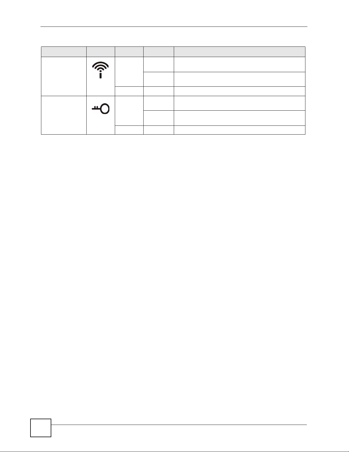
The following table describes the LEDs.
Table 1 Front Panel LEDs
LED ICON COLOR STATUS DESCRIPTION
POWER Green On The PLA450 is receiving power and functioning
properly.
Off The PLA450 is not receiving power.
HomePlug Green On The PLA450 has a successful HomePlug AV
connection.
The PLA450 v2 has a successful HomePlug AV
connection at 40 Mbps.
Blinking The PLA450 is sending/receiving data.
The PLA450 v2 is sending/receiving data at over 40
Mbps.
Amber On The PLA450 v2 has a successful HomePlug AV
Blinking The PLA450 v2 is sending/receiving data at 10~40
Red On The PLA450 v2 has a successful HomePlug AV
Blinking The PLA450 v2 is sending/receiving data at 0~10
Off The HomePlug AV connection is not ready, or failed.
LAN Green On The PLA450 has a successful Ethernet connection.
Blinking The PLA450 is sending/receiving data.
Off The LAN is not connected.
connection at 10~40 Mbps.
Mbps.
connection at 0~10 Mbps.
Mbps.
PLA450 User’s Guide
25
Page 26
Chapter 1 Getting to Know Your PLA450
Table 1 Front Panel LEDs (continued)
LED ICON COLOR STATUS DESCRIPTION
WLAN Green On The PLA450 is ready, but is not sending/receiving data
through the wireless LAN.
Blinking The PLA450 is sending/receiving data through the
wireless LAN.
Off The wireless LAN is not ready or has failed.
WPS Green On WPS (WiFi Protected Setup) is configured on your
Blinking The PLA450 is setting up a WPS connection with
Off WPS is disabled on your device.
device.
another WPS-enabled device.
26
PLA450 User’s Guide
Page 27

CHAPTER 2
The WPS Button
2.1 Overview
Your PLA450 supports WiFi Protected Setup (WPS), which is an easy way to set up a secure
wireless network. WPS is an industry standard specification, defined by the WiFi Alliance.
WPS allows you to quickly set up a wireless network with strong security, without having to
configure security settings manually. Each WPS connection works between two devices. Both
devices must support WPS (check each device’s documentation to make sure).
Depending on the devices you have, you can either press a button (on the device itself, or in its
configuration utility) or enter a PIN (a unique Personal Identification Number that allows one
device to authenticate the other) in each of the two devices. When WPS is activated on a
device, it has two minutes to find another device that also has WPS activated. Then, the two
devices connect and set up a secure network by themselves.
2.2 Push Button Configuration
WPS Push Button Configuration (PBC) is initiated by pressing a button on each WPS-enabled
device, and allowing them to connect automatically. You do not need to enter any information.
Not every WPS-enabled device has a physical WPS button. Some may have a WPS PBC
button in their configuration utilities instead of or in addition to the physical button.
Take the following steps to set up WPS using the button.
1 Ensure that the two devices you want to set up are within wireless range of one another.
2 Look for a WPS button on each device. If the device does not have one, log into its
configuration utility and locate the button (see the device’s User’s Guide for how to do
this - for the PLA450, see Section 6.10 on page 78).
3 Press the button on one of the devices (it doesn’t matter which).
4 Within two minutes, press the button on the other device. The registrar sends the
network name (SSID) and security key through an secure connection to the enrollee.
If you need to make sure that WPS worked, check the list of associated wireless clients in the
AP’s configuration utility. If you see the wireless client in the list, WPS was successful.
For information on using the WPS PIN method, see Section 6.5.1 on page 64.
PLA450 User’s Guide
27
Page 28

Chapter 2
28
PLA450 User’s Guide
Page 29

CHAPTER 3
The ENCRYPT Button
Use the ENCRYPT button to automatically set up a secure powerline connection between
your powerline devices.
3.1 ENCRYPT Button Overview
The ENCRYPT button allows you to set up a secure powerline connection with other
HomePlug AV compliant powerline devices which also support the ENCRYPT feature. No
other powerline setting changes are required to connect.
You can use the ENCRYPT button to:
• set up a new powerline network
• separate an existing powerline network into multiple networks
" You need to have version 3.0.5 firmware or later installed to enable the
ENCRYPT feature.
3.2 Set Up a HomePlug AV Network with ENCRYPT
You can connect a number of devices on a powerline network, but you can use the ENCRYPT
button on only two devices at a time. The PLA450 and PLA-400 v2 are shown below as
examples.
1 Place a powerline device close to another powerline device so you have time to set up
each one. After you set up the first powerline device, you have 120 seconds to set up the
second powerline device.
2 You can disconnect them from your computer or modem (or other networking
equipment) if you need to move them close to each other, but the powerline devices
need to be plugged into power outlets.
3 Press the ENCRYPT button at the rear of your powerline device for more than 10
seconds until the HomePlug ( ) light is off. This resets the network name to a random
value and removes your device from any network it may belong to.
4 Press the ENCRYPT button at the rear of your powerline device for 1~2 seconds.
PLA450 User’s Guide
29
Page 30

Chapter 3 The ENCRYPT Button
Figure 4 ENCRYPT Connection Procedure
5 Repeat step 4 in this section for the other powerline device you wish to connect. This
must be done within 120 seconds of pressing the ENCRYPT button on the PLA450.
6 Check the lights on the two powerline devices. Wait for about one minute while your
powerline devices connect. The HomePlug ( ) lights on both devices turn on when the
connection is made.
press 2 seconds
press 2 seconds
within 2
minutes
V If the HomePlug ( ) lights on both powerline devices do not light up, the
powerline devices are not connected. Repeat steps 3, 4 and 5 in this
section. If that doesn’t work, see the Troubleshooting in Section 14.7 on page
120 for suggestions.
7 To add more powerline devices to your network, press the ENCRYPT button on device
C (shown below) for more than 10 seconds until the HomePlug ( ) light flashes.
8 Then repeat steps 4 and 5 in this section using any powerline device (A or B) you have
connected using ENCRYPT and the powerline device you want to connect (C). You
must use the ENCRYPT button on both devices.
30
PLA450 User’s Guide
Page 31

Chapter 3 The ENCRYPT Button
Figure 5 Adding More Powerline Adapters to Your Network
A
OR
AB
C
9 If you disconnected your computer or modem (or any other networking product
connected to your powerline device) in step 1 of this section, you can now reconnect
them.
This sets up your powerline network between your powerline devices.
B
3.3 Setting Up Multiple Networks
You can use the ENCRYPT button to set up multiple powerline networks using your existing
powerline network.
For example, you have already set up a powerline network in your home (A) which accesses a
printer (B). Now you want a separate powerline network connection from your laptop to your
printer (C).
Figure 6 One Existing Powerline Network
A
B
C
PLA450 User’s Guide
31
Page 32

Chapter 3 The ENCRYPT Button
1 Click the ENCRYPT button on (A) for more than 10 seconds until the HomePlug ( )
light is off. This disconnects (A) from (B).
2 Click the ENCRYPT button on (A) and (C) for 1~2 seconds and within two minutes of
each other.
3 Wait for about one minute while (A) and (C) connect.
4 Check the lights on both (A) and (C). When the HomePlug ( ) lights shine steadily,
the devices are connected.
Figure 7 Two Separate Powerline Networks
A
B
C
Congratulations. You now have two separate powerline networks as shown above.
V If the HomePlug ( ) lights on both powerline devices do not light up, the
powerline devices are not connected. Repeat the connection process, making
certain you press the ENCRYPT buttons for the correct time and within two
minutes of each other. If that does not work see Section 14.7 on page 120 for
suggestions.
3.4 ENCRYPT Button Behavior
The following table summarizes the actions that occur when the ENCRYPT button is pressed
for specific lengths of time.
Table 2 Time ENCRYPT Button is Pressed and Action
TIME ACTION
less than 3
seconds
more than
10 seconds
The device joins a network. It
shares the same network name
as other devices on the network.
The device leaves any network
it is associated with and its
network name assumes a
random value.
HOMEPLUG LIGHT
BEHAVIOR
The HomePlug ( ) light turns
on if your device is connected to
another powerline device or a
powerline network.
The HomePlug ( ) light turns
off when it disconnects from the
powerline network.
32
PLA450 User’s Guide
Page 33

Chapter 3 The ENCRYPT Button
See Troubleshooting in Chapter 14 on page 120 for suggestions on problems with the
ENCRYPT button and the lights.
PLA450 User’s Guide
33
Page 34

Chapter 3 The ENCRYPT Button
34
PLA450 User’s Guide
Page 35

CHAPTER 4
Introducing the Web
Configurator
This chapter describes how to access the PLA450 web configurator and provides an overview
of its screens.
4.1 Web Configurator Overview
The web configurator is an HTML-based management interface that allows easy setup and
management of the PLA450 via Internet browser. Use Internet Explorer 6.0 and later or
Netscape Navigator 7.0 and later versions. The recommended screen resolution is 1024 by 768
pixels.
In order to use the web configurator you need to allow:
• Web browser pop-up windows from your device. Web pop-up blocking is enabled by
default in Windows XP SP (Service Pack) 2.
• JavaScripts (enabled by default).
• Java permissions (enabled by default).
Refer to the Troubleshooting chapter to see how to make sure these functions are allowed in
Internet Explorer.
4.2 Accessing the Web Configurator
1 Make sure your PLA450 hardware is properly connected and prepare your computer or
computer network to connect to the PLA450 (refer to the Quick Start Guide).
2 Launch your web browser.
3 Type "http://192.168.1.2" as the URL.
4 Type "1234" (default) as the password and click Login. In some versions, the default
password appears automatically - if this is the case, click Login.
5 You should see a screen asking you to change your password (highly recommended) as
shown next. Type a new password (and retype it to confirm) and click Apply or click
Ignore.
PLA450 User’s Guide
35
Page 36

Chapter 4 Introducing the Web Configurator
Figure 8 Change Password Screen
" The management session automatically times out when the time period set in
the Administrator Inactivity Timer field expires (default five minutes). Simply
log back into the PLA450 if this happens.
6 Select the setup mode you want to use.
• Click Go to Basic Setup if you want to view and configure basic settings. Not all Web
Configurator screens are available in this mode.
• Click Go to Advanced Setup to view and configure all the PLA450’s settings.
Figure 9 Choose Basic or Advanced Screen
36
PLA450 User’s Guide
Page 37

Chapter 4 Introducing the Web Configurator
4.3 Resetting the PLA450
If you forget your password or cannot access the web configurator, you will need to use the
RESET button at the back of the PLA450 to reload the factory-default configuration file. This
means that you will lose all configurations that you had previously saved, and the password
will be reset to “1234”.
4.3.1 Procedure to Use the Reset Button
1 Make sure the PWR LED is on.
2 Press the RESET button for ten seconds or until the PWR LED begins to blink and then
release it. When the PWR LED begins to blink, the defaults have been restored and the
PLA450 restarts.
4.4 Navigating the Web Configurator
The following summarizes how to navigate the web configurator from the Status screen.
4.4.1 The Status Screen
The following screen displays when you log into the PLA450.
" Not all screens are available when you select Basic mode (Table 35 on page
111 lists which screens are only available in Advanced mode). See the
Configuration Mode field in the System Status box to check whether you are
in Basic or Advanced mode. Use the Config Mode > General screen to
change between modes.
PLA450 User’s Guide
37
Page 38

Chapter 4 Introducing the Web Configurator
Figure 10 Web Configurator Status Screen
The following table describes the icons shown in the Status screen.
Table 3 Status Screen Icon Key
ICON DESCRIPTION
Click this icon to view copyright and a link for related product information.
Click this icon at any time to exit the web configurator.
Select a number of seconds or None from the drop-down list box to refresh all screen
statistics automatically at the end of every time interval or to not refresh the screen
statistics.
Click this button to refresh the status screen statistics.
The following table describes the labels shown in the Status screen.
Table 4 Web Configurator Status Screen
LABEL DESCRIPTION
Device Information
System Name This is the System Name you enter in the Maintenance > System >
Firmware Version This is the ZyNOS firmware version and the date created. ZyNOS is
LAN Information
General screen. It is for identification purposes.
ZyXEL's proprietary Network Operating System.
38
PLA450 User’s Guide
Page 39

Chapter 4 Introducing the Web Configurator
Table 4 Web Configurator Status Screen (continued)
LABEL DESCRIPTION
- MAC Address This shows the LAN Ethernet adapter MAC Address of your device.
- IP Address This shows the LAN port’s IP address.
- IP Subnet Mask This shows the LAN port’s subnet mask.
- DHCP This shows the LAN port’s DHCP role - Server or None.
WLAN Information
- MAC Address This shows the wireless adapter MAC Address of your device.
- Name (SSID) This shows a descriptive name used to identify the PLA450 in the wireless
LAN.
- Channel This shows the channel number which you select manually.
- Operating Channel This shows the channel number which the PLA450 is currently using over
the wireless LAN.
- Security Mode This shows the level of wireless security the PLA450 is using.
- 802.11 Mode This shows the wireless standard.
- Super G Mode This shows whether SuperG is enabled or not.
- WPS This shows the status of Wi-Fi Protected Setup (WPS) on your device.
HomePlug
Information
- MAC Address This shows the MAC Address of your device.
- Firmware Version This shows the firmware version of the HomePlug chipset.
System Status
System Uptime This is the total time the PLA450 has been on.
Current Date/Time This field displays your PLA450’s present date and time.
System Resource
- CPU Usage This displays what percentage of the PLA450’s processing ability is
currently used. When this percentage is close to 100%, the PLA450 is
running at full load, and the throughput is not going to improve anymore. If
you want some applications to have more throughput, you should turn off
other applications.
- Memory Usage This shows what percentage of the heap memory the PLA450 is using.
Heap memory refers to the memory that is not used by ZyNOS (ZyXEL
Network Operating System) and is thus available for running the PLA450’s
processes.
System Setting
- Configuration Mode This shows whether the advanced screens of each feature are turned on
Interface Status
Interface This displays the PLA450 port types. The port types are: LAN, WLAN and
Status For the LAN port, this field displays Down (line is down) or Up (line is up or
(Advanced) or not (Basic).
HomePlug AV.
connected).
For the WLAN, it displays Up when the WLAN is enabled or Down when
the WLAN is disabled.
For the HomePlug AV port it displays Up when the power cord is
connected.
PLA450 User’s Guide
39
Page 40

Chapter 4 Introducing the Web Configurator
Table 4 Web Configurator Status Screen (continued)
LABEL DESCRIPTION
Rate For the LAN port, this displays the port speed and duplex setting or N/A
when the line is disconnected.
For the WLAN, it displays the maximum transmission rate when the WLAN
is enabled and N/A when the WLAN is disabled.
For the HomePlug AV port it displays the maximum transmission rate
when HomePlug AV is enabled.
Summary
Packet Statistics Click Details to view port status and packet specific statistics.
WLAN Station Status Click Details to view the wireless stations that are currently associated to
the PLA450.
My HomePlug
Network
Click Details to view information on the stations connected to your Home
Plug network.
4.4.2 Navigation Panel
After you enter the password, use the sub-menus on the navigation panel to configure PLA450
features.
The following table describes the sub-menus.
Table 5 Screens Summary
LINK TAB FUNCTION
Status This screen shows the PLA450’s general device, system and
interface status information. Use this screen to access the
summary statistics tables.
Network
Wireless
LAN
LAN IP Use this screen to configure LAN IP address and subnet mask.
HomePlug Network
Maintenance
System General Use this screen to view and change administrative settings such as
General Use this screen to configure wireless LAN.
MAC Filter Use the MAC filter screen to configure the PLA450 to block access
Advanced This screen allows you to configure advanced wireless settings.
QoS Use this screen to configure Wi-Fi Multimedia Quality of Service
WPS Use this screen to configure Wi-Fi Protected Setup (WPS) settings.
WPS Station Use this screen to use WPS to set up your wireless network.
Settings
QoS Use this screen to configure HomePlug AV Quality of Service. This
Time Setting Use this screen to change your PLA450’s time and date.
to devices or block the devices from accessing the PLA450.
(WMM QoS). WMM QoS allows you to prioritize wireless traffic
according to the delivery requirements of individual services.
Use this screen to configure HomePlug AV devices and set up a
powerline network.
allows you to prioritize powerline traffic according to the delivery
requirements of individual services.
system and domain names, password and inactivity timer.
40
PLA450 User’s Guide
Page 41

Table 5 Screens Summary
LINK TAB FUNCTION
Logs View Log Use this screen to view the logs for the categories that you
selected.
Log Settings Use this screen to change your PLA450’s log settings.
To ols Firmware Use this screen to upload firmware to your PLA450.
Configuration Use this screen to backup and restore the configuration or reset
the factory defaults to your PLA450.
Restart This screen allows you to reboot the PLA450 without turning the
power off.
Config Mode General This screen allows you to display or hide the advanced screens or
features.
Language Language This allows you to change the web configurator’s language
settings.
4.4.3 Summary: Packet Statistics
Click the Packet Statistics (Details...) hyperlink in the Status screen. Read-only information
here includes port status and packet specific statistics. Also provided are "system up time" and
"poll interval(s)". The Poll Interval(s) field is configurable.
Chapter 4 Introducing the Web Configurator
Figure 11 Summary: Packet Statistics
The following table describes the labels in this screen.
Table 6 Summary: Packet Statistics
LABEL DESCRIPTION
Port This is the PLA450’s port type.
Status For the LAN ports, this displays the port speed and duplex setting or Down
when the line is disconnected.
For the WLAN, it displays the maximum transmission rate when the WLAN is
enabled and Down when the WLAN is disabled.
TxPkts This is the number of transmitted packets on this port.
RxPkts This is the number of received packets on this port.
Collisions This is the number of collisions on this port.
Tx B/s This displays the transmission speed in bytes per second on this port.
PLA450 User’s Guide
41
Page 42

Chapter 4 Introducing the Web Configurator
Table 6 Summary: Packet Statistics
LABEL DESCRIPTION
Rx B/s This displays the reception speed in bytes per second on this port.
Up Time This is the total amount of time the line has been up.
System Up Time This is the total time the PLA450 has been on.
Poll Interval(s) Enter the time interval for refreshing statistics in this field.
Set Interval Click this button to apply the new poll interval you entered in the Poll Interval(s)
field.
Stop Click Stop to stop refreshing statistics, click Stop.
4.4.4 Summary: Wireless Station Status
Click the WLAN Station Status (Details...) hyperlink in the Status screen. View the wireless
stations that are currently associated to the PLA450 in the Association List screen.
Figure 12 Summary: Wireless Association List
The following table describes the labels in this screen.
Table 7 Summary: Wireless Association List
LABEL DESCRIPTION
# This is the index number of an associated wireless station.
MAC Address This field displays the MAC address of an associated wireless station.
Association Time This field displays the time a wireless station first associated with the PLA450.
Refresh Click Refresh to reload the list.
4.4.5 Summary: My HomePlug Network Status
Click the My HomePlug Network (Details...) hyperlink in the Status screen. View the
powerline stations that are currently associated to the PLA450 in the My Homeplug Network
screen.
42
PLA450 User’s Guide
Page 43

Chapter 4 Introducing the Web Configurator
Figure 13 Summary: My Homeplug Network.
The following table describes the labels in this screen.
Table 8 Summary: My Homeplug Network
LABEL DESCRIPTION
Site This PLA450 is the Local device. All other devices on your network will be
Remote.
MAC Address This field displays the MAC address of a HomePlug AV device detected by your
PLA450.
Firmware Version This shows the firmware version used by the HomePlug chipset.
Rx (Mbps) This displays the reception speed in megabytes per second on the powerline
port.
Tx (Mbps) This displays the transmission speed in megabytes per second on the powerline
Details Click the details icon to display statistics on the connection between the remote
Refresh Click Refresh to reload the list.
port.
device and the local device.
Click the Details icon to display the following screen.
This screen displays information on the selected powerline device’s connection status with the
local device. Use this information for troubleshooting powerline connection problems. See the
Troubleshooting in Section 14.6 on page 119 for suggestions.
PLA450 User’s Guide
43
Page 44

Chapter 4 Introducing the Web Configurator
The following table describes the labels in this screen.
Table 9 Summary: My Homeplug Network
LABEL DESCRIPTION
Statistics
MAC Address This field displays the MAC address of the powerline device detected by your
PLA450.
Rx PHY Rate This field shows the transfer rate of data received by the local device from the
selected remote device, measured in Mbps.
Tx PHY Rate This field shows the transfer rate of data sent the local device to the selected
powerline device, measured in Mbps.
Avg. Pre-FEC
Bit Error Rate
Avg. Source PB
CRC Error Rate
Avg. Dest PB
CRC Error Rate
Avg. Bits This field displays the average number of bits transferred over the connection
Avg. SNR This field displays the average SNR (Signal to Noise Ratio) measured in dB.
In powerline networks data is sent in physical blocks (PB). This field shows the
average percentage of errors in the physical blocks sent by the destination
device to your local device before the errors are corrected using FEC (Forward
Error Correction).
A high error rate may not necessarily result in a poor connection as PBs with
errors are discarded and the powerline device adjusts the signal to a frequency
to a level where fewer errors occur
This field displays the average CRC (Cyclic Redundancy Check) error rate of
transmission from the destination device to the local device.
The CRC error check is performed after Forward Error Correction. If the error
rate after FEC error correction is still high, then this indicates a lot of noise at all
frequencies on this section of your powerline. Data transmission rates are
reduced if there is a lot of noise on the line.
This field displays the average CRC (Cyclic Redundancy Check) error rate of
transmission sent from the local device to the selected powerline device.
The CRC error check is performed after Forward Error Correction. If the error
rate after FEC error correction is still high, then this indicates a lot of noise at all
frequencies on this section of your powerline. Data transmission rates are
reduced if there is a lot of noise on the line.
measured in Mbps. This represents the physical rate of data transmission (the
PHY rate) which includes not only the files sent on your powerline, but also line
overhead required to manage your network, such as error correction bits.
The PHY rate is the clearest indicator of the quality of your line.
• If the PHY rate is close to the HomePlug AV maximum data transfer rate
(see Chapter 15 on page 123), then the quality of this section of the line is
very high, with very little attenuation. (See Avg. Attenuation for details on
attenuation).
• If the PHY rate varies between the maximum level and a lower level (such as
60 Mbps), there is noise on this section of your powerline. Attenuation is not
a factor.
If the PHY rate is steady at a lower level (such as 80 Mbps), this is caused by
attenuation and not noise on this section of your powerline
Use this to check the amount of noise on this part of your powerline network.
The higher the number the better the connection quality.
Noise on your powerline is usually caused by household appliances running on
your powerline. The motor of a refrigerator can create electrical interference. A
cell/mobile phone recharger which rapidly alternates between on and off can
also generate noise. Poor cable quality and installation can also cause noise. To
identify causes of noise on your network, disconnect an appliance connected on
this part of your powerline network and observe whether this reduces the Signalto-Noise ratio.
44
PLA450 User’s Guide
Page 45

Chapter 4 Introducing the Web Configurator
Table 9 Summary: My Homeplug Network
LABEL DESCRIPTION
Avg. Attenuation This field displays the average attenuation measured in dB. Attenuation is the
reduction in strength of a signal as it travels over a transmission line. Use this
field to check the reduction in the strength of the signal between two devices.
Attenuation may vary considerably across a powerline network as line
conditions also vary. A typical level of attenuation may be 40 dB, but may reach
over 70 dB, depending on line quality and distance.
A main cause of attenuation is the power requirements of appliances on your
electrical circuit. Powerline traffic near an appliance such as a refrigerator may
be affected by attenuation more than on other sections of your powerline.
Avg. Output
Power
This field shows the average power produced by the device. Power levels
should be constant and limited by the output power standard of your country.
Unusually high output power levels may damage your device.
PLA450 User’s Guide
45
Page 46

Chapter 4 Introducing the Web Configurator
46
PLA450 User’s Guide
Page 47

CHAPTER 5
Wireless Tutorial
This chapter gives you examples of how to set up the PLA450 and wireless client for wireless
communication using the following parameters. The wireless clients can access the Internet
through the PLA450 wirelessly. See Chapter 6 on page 57 for more on the PLA450’s wireless
LAN configuration.
5.1 Example Parameters
SSID SSID_Example3
Channel 6
Security WPA-PSK
(Pre-Shared Key: ThisismyWPA-PSKpre-sharedkey)
802.11 mode IEEE 802.11b/g
In this chapter, the PLA450 is also referred to as an access point (AP). A computer with a
wireless network card or USB/PCI adapter is referred to here as a “wireless client”.
This chapter uses the M-302 utility screens as an example for the wireless client. The screens
may vary for different models.
5.2 Configuring the PLA450
Follow the steps below to configure the wireless settings on your PLA450.
1 Open the Network > Wireless LAN > General screen in the web configurator.
PLA450 User’s Guide
47
Page 48

Chapter 5 Wireless Tutorial
Figure 14 Network > Wireless LAN > General
2 Make sure the Enable Wireless LAN check box is selected.
3 Enter SSID_Example3 as the SSID and select a channel.
4 Set security mode to WPA-PSK and enter ThisismyWPA-PSKpre-sharedkey in the
Pre-Shared Key field. Click Apply.
5 Open the Status screen.Verify your wireless and wireless security settings under Device
Information and check if the WLAN connection is up under Interface Status.
48
PLA450 User’s Guide
Page 49

Figure 15 Status: Wireless Settings Example
Chapter 5 Wireless Tutorial
6 Click the WLAN Station Status hyperlink in the AP’s Status screen. You can see if any
wireless client has connected to the AP.
Figure 16 AP: Status: WLAN Station Status
5.3 Configuring the Wireless Client
This section describes how to connect the wireless client to a network.
5.3.1 Connecting to a Wireless LAN
The following sections show you how to join a wireless network using the ZyXEL utility, as in
the following diagram. The wireless client is labelled C and the access point (PLA450) is
labelled AP. D is the broadband modem.
PLA450 User’s Guide
49
Page 50

Chapter 5 Wireless Tutorial
Figure 17 Connecting to a Wireless LAN
C
There are three ways to connect the client to an access point.
• Configure nothing and leave the wireless client to automatically scan for and connect to
any available network that has no wireless security configured.
• Manually connect to a network.
• Configure a profile to have the wireless client automatically connect to a specific network
or peer computer.
This example illustrates how to manually connect your wireless client to an access point (AP)
which is configured for WPA-PSK security and connected to the Internet. Before you connect
to the access point, you must know its Service Set IDentity (SSID) and WPA-PSK pre-shared
key. In this example, the SSID is “SSID_Example3” and the pre-shared key is
“ThisismyWPA-PSKpre-sharedkey”.
D
AP
After you install the ZyXEL utility and then insert the wireless client, follow the steps below
to connect to a network using the Site Survey screen.
1 Open the ZyXEL utility and click the Site Survey tab to open the screen shown next.
2 The wireless client automatically searches for available wireless networks. Click Scan if
you want to search again. If no entry displays in the Available Network List, that means
there is no wireless network available within range. Make sure the AP or peer computer
is turned on or move the wireless client closer to the AP or peer computer.
3 When you try to connect to an AP with security configured, a window will pop up
prompting you to specify the security settings. Enter the pre-shared key and leave the
encryption type at the default setting.
50
PLA450 User’s Guide
Page 51

Chapter 5 Wireless Tutorial
Use the Next button to move on to the next screen. You can use the Back button at any
time to return to the previous screen, or the Exit button to return to the Site Survey
screen.
Figure 18 ZyXEL Utility: Security Settings
4 The Confirm Save window appears. Check your settings and click Save to continue.
Figure 19 ZyXEL Utility: Confirm Save
5 The ZyXEL utility returns to the Link Info screen while it connects to the wireless
network using your settings. When the wireless link is established, the ZyXEL utility
icon in the system tray turns green and the Link Info screen displays details of the active
connection. Check the network information in the Link Info screen to verify that you
have successfully connected to the selected network. If the wireless client is not
connected to a network, the fields in this screen remain blank.
Figure 20 ZyXEL Utility: Link Info
PLA450 User’s Guide
51
Page 52

Chapter 5 Wireless Tutorial
6 Open your Internet browser and enter http://www.zyxel.com or the URL of any other
web site in the address bar. If you are able to access the web site, your wireless
connection is successfully configured.
If you cannot access the web site, try changing the encryption type in the Security
Settings screen, check the Troubleshooting section of this User's Guide or contact your
network administrator.
5.3.2 Creating and Using a Profile
A profile lets you automatically connect to the same wireless network every time you use the
wireless client. You can also configure different profiles for different networks, for example if
you connect a notebook computer to wireless networks at home and at work.
This example illustrates how to set up a profile and connect the wireless client to an access
point configured for WPA-PSK security. In this example, the SSID is “SSID_Example3”, the
profile name is “PN_Example3” and the pre-shared key is “ThisismyWPA-PSKpresharedkey”. You have chosen the profile name “PN_Example3”.
1 Open the ZyXEL utility and click the Profile tab to open the screen shown next. Click
Add to configure a new profile.
Figure 21 ZyXEL Utility: Profile
2 The Add New Profile screen appears. The wireless client automatically searches for
available wireless networks, which are displayed in the Scan Info box. Click on Scan if
you want to search again. You can also configure your profile for a wireless network that
is not in the list.
Figure 22 ZyXEL Utility: Add New Profile
52
PLA450 User’s Guide
Page 53

Chapter 5 Wireless Tutorial
3 Give the profile a descriptive name (of up to 32 printable ASCII characters). Select
Infrastructure and either manually enter or select the AP's SSID in the Scan Info table
and click Select.
4 Choose the same encryption method as the AP to which you want to connect (In this
example, WPA-PSK).
Figure 23 ZyXEL Utility: Profile Security
5 This screen varies depending on the encryption method you selected in the previous
screen. Enter the pre-shared key and leave the encryption type at the default setting.
Figure 24 ZyXEL Utility: Profile Encryption
6 In the next screen, leave both boxes checked.
Figure 25 Profile: Wireless Protocol Settings.
7 Verify the profile settings in the read-only screen. Click Save to save and go to the next
screen.
PLA450 User’s Guide
53
Page 54

Chapter 5 Wireless Tutorial
Figure 26 Profile: Confirm Save
8 Click Activate Now to use the new profile immediately. Otherwise, click the Activate
Later button.
If you clicked Activate Later, you can select the profile from the list in the Profile
screen and click Connect to activate it.
" Only one profile can be activated and used at any given time.
Figure 27 Profile: Activate
9 When you activate the new profile, the ZyXEL utility returns to the Link Info screen
while it connects to the AP using your settings. When the wireless link is established, the
ZyXEL utility icon in the system tray turns green and the Link Info screen displays
details of the active connection.
10 Open your Internet browser, enter http://www.zyxel.com or the URL of any other web
site in the address bar and press ENTER. If you are able to access the web site, your new
profile is successfully configured.
11 If you cannot access the Internet go back to the Profile screen, select the profile you are
using and click Edit. Check the details you entered previously. Also, refer to the
Troubleshooting section of this User's Guide or contact your network administrator if
necessary.
54
PLA450 User’s Guide
Page 55

PART II
Wireless LAN (57)
LAN (81)
HomePlug AV (85)
Network
55
Page 56

56
Page 57

CHAPTER 6
Wireless LAN
This chapter discusses how to configure the wireless network settings in your PLA450. See the
appendices for more detailed information about wireless networks.
6.1 Wireless Network Overview
The following figure provides an example of a wireless network.
Figure 28 Example of a Wireless Network
AP
A
The wireless network is the part in the blue circle. In this wireless network, devices A and B
are called wireless clients. The wireless clients use the access point (AP) to interact with other
devices (such as the printer) or with the Internet. Your PLA450 is the AP.
Every wireless network must follow these basic guidelines.
• Every wireless client in the same wireless network must use the same SSID.
The SSID is the name of the wireless network. It stands for Service Set IDentity.
• If two wireless networks overlap, they should use different channels.
B
PLA450 User’s Guide
57
Page 58

Chapter 6 Wireless LAN
Like radio stations or television channels, each wireless network uses a specific channel,
or frequency, to send and receive information.
• Every wireless client in the same wireless network must use security compatible with the
AP.
Security stops unauthorized devices from using the wireless network. It can also protect
the information that is sent in the wireless network.
Requirements
To add a wireless LAN to your existing network, make sure you have the following:
1 an access point (AP) or a router with the wireless feature
2 at least one wireless network card/adapter which varies according to your computer.
• If you have a desktop, use either a wireless USB adapter or a wireless PCI adapter.
• If you have a laptop, use either a wireless USB adapter or a wireless CardBus card.
3 a RADIUS server only if you want to use WPA or WPA2.
To have two or more computers communicate with each other wirelessly without an AP or
wireless router, make sure you have the following:
1 two or more wireless network cards/adapters which vary according to your computers.
• If you have a desktop, use either a wireless USB adapter or a wireless PCI adapter.
• If you have a laptop, use either a wireless USB adapter or a wireless CardBus card.
Setup Information
To set up your wireless network using an AP or wireless router, make sure your AP or wireless
router and wireless network card(s)/adapter(s) use the same following settings:
• SSID:_____________________
• Channel: _________
• Network type of a wireless network card/adapter: Infrastructure
• wireless standard: IEEE 802.11b, g, or b/g
• Security:
( ) None
( ) WEP (64 bit or 128 bit key) (ASCII or Hex):________________
( ) WPA-PSK (TKIP):_______________
( ) WPA (TKIP)
( ) WPA2-PSK (AES):______________
( ) WPA2 (AES)
• Preamble type (if available): auto, short or long
58
To set up your wireless network without an AP or wireless router, make sure wireless network
cards/adapters use the same following settings:
• Network type: Ad-Hoc
• SSID:_____________________
• Channel: _________________
• wireless standard: IEEE 802.11b, g, or b/g
PLA450 User’s Guide
Page 59

• Security:
( ) None
( ) WEP (64 bit or 128 bit key) (ASCII or Hex):________________
6.2 Wireless Security Overview
The following sections introduce different types of wireless security you can set up in the
wireless network.
6.2.1 SSID
Normally, the AP acts like a beacon and regularly broadcasts the SSID in the area. You can
hide the SSID instead, in which case the AP does not broadcast the SSID. In addition, you
should change the default SSID to something that is difficult to guess.
This type of security is fairly weak, however, because there are ways for unauthorized devices
to get the SSID. In addition, unauthorized devices can still see the information that is sent in
the wireless network.
Chapter 6 Wireless LAN
6.2.2 MAC Address Filter
Every wireless client has a unique identification number, called a MAC address.1 A MAC
address is usually written using twelve hexadecimal characters
or 00:A0:C5:00:00:02. To get the MAC address for each wireless client, see the appropriate
User’s Guide or other documentation.
You can use the MAC address filter to tell the AP which wireless clients are allowed or not
allowed to use the wireless network. If a wireless client is allowed to use the wireless network,
it still has to have the correct settings (SSID, channel, and security). If a wireless client is not
allowed to use the wireless network, it does not matter if it has the correct settings.
This type of security does not protect the information that is sent in the wireless network.
Furthermore, there are ways for unauthorized devices to get the MAC address of an authorized
wireless client. Then, they can use that MAC address to use the wireless network.
6.2.3 User Authentication
You can make every user log in to the wireless network before they can use it. This is called
user authentication. However, every wireless client in the wireless network has to support the
authentication method to do this.
For wireless networks, there are two typical places to store the user names and passwords for
each user.
2
; for example, 00A0C5000002
• In the AP: this feature is called a local user database or a local database.
• In a RADIUS server: this is a server used in businesses more than in homes.
1. Some wireless devices, such as scanners, can detect wireless networks but cannot use wireless networks.
These kinds of wireless devices might not have MAC addresses.
2. Hexadecimal characters are 0, 1, 2, 3, 4, 5, 6, 7, 8, 9, A, B, C, D, E, and F.
PLA450 User’s Guide
59
Page 60

Chapter 6 Wireless LAN
If your AP does not provide a local user database and if you do not have a RADIUS server,
you cannot set up user names and passwords for your users.
Unauthorized devices can still see the information that is sent in the wireless network, even if
they cannot use the wireless network. Furthermore, there are ways for unauthorized wireless
users to get a valid user name and password. Then, they can use that user name and password
to use the wireless network.
Local user databases also have an additional limitation that is explained in the next section.
6.2.4 Encryption
Wireless networks can use encryption to protect the information that is sent in the wireless
network. Encryption is like a secret code. If you do not know the secret code, you cannot
understand the message.
The types of encryption you can choose depend on the type of user authentication. (See
Section 6.2.3 on page 59 for information about this.)
Table 10 Types of Encryption for Each Type of Authentication
Weakest No Security WPA
Strongest WPA2-PSK WPA2
NO AUTHENTICATION RADIUS SERVER
Static WEP
WPA-PSK
For example, if the wireless network has a RADIUS server, you can choose WPA or WPA2.
If users do not log in to the wireless network, you can choose no encryption, Static WEP,
WPA-PSK, or WPA2-PSK.
Usually, you should set up the strongest encryption that every wireless client in the wireless
network supports. For example, suppose the AP does not have a local user database, and you
do not have a RADIUS server. Therefore, there is no user authentication. Suppose the wireless
network has two wireless clients. Device A only supports WEP, and device B supports WEP
and WPA. Therefore, you should set up Static WEP in the wireless network.
" It is recommended that wireless networks use WPA-PSK, WPA, or stronger
encryption. WEP encryption is better than none at all, but it is still possible for
unauthorized devices to figure out the original information pretty quickly.
It is not possible to use WPA-PSK, WPA or stronger encryption with a local user database. In
this case, it is better to set up stronger encryption with no authentication than to set up weaker
encryption with the local user database.
When you select WPA2 or WPA2-PSK in your PLA450, you can also select an option (WPA
Compatible) to support WPA as well. In this case, if some wireless clients support WPA and
some support WPA2, you should set up WPA2-PSK or WPA2 (depending on the type of
wireless network login) and select the WPA Compatible option in the PLA450.
60
PLA450 User’s Guide
Page 61

Many types of encryption use a key to protect the information in the wireless network. The
longer the key, the stronger the encryption. Every wireless client in the wireless network must
have the same key.
6.3 Roaming
A wireless station is a device with an IEEE 802.11a/b/g compliant wireless interface. An
access point (AP) acts as a bridge between the wireless and wired networks. An AP creates its
own wireless coverage area. A wireless station can associate with a particular access point
only if it is within the access point’s coverage area.
In a network environment with multiple access points, wireless stations are able to switch from
one access point to another as they move between the coverage areas. This is known as
roaming. As the wireless station moves from place to place, it is responsible for choosing the
most appropriate access point depending on the signal strength, network utilization or other
factors.
The roaming feature on the access points allows the access points to relay information about
the wireless stations to each other. When a wireless station moves from a coverage area to
another, it scans and uses the channel of a new access point, which then informs the other
access points on the LAN about the change. An example is shown in Figure 29 on page 62.
Chapter 6 Wireless LAN
With roaming, a wireless LAN mobile user enjoys a continuous connection to the wired
network through an access point while moving around the wireless LAN.
Enable roaming to exchange the latest bridge information of all wireless stations between APs
when a wireless station moves between coverage areas. Wireless stations can still associate
with other APs even if you disable roaming. Enabling roaming ensures correct traffic
forwarding (bridge tables are updated) and maximum AP efficiency. The AP deletes records
of wireless stations that associate with other APs (Non-ZyXEL APs may not be able to
perform this).
PLA450 User’s Guide
61
Page 62

Chapter 6 Wireless LAN
Figure 29 Roaming Example
AP 1
X
Y Y
The steps below describe the roaming process.
1 Wireless station Y moves from the coverage area of access point AP 1 to that of access
point AP 2.
2 Wireless station Y scans and detects the signal of access point AP 2.
3 Wireless station Y sends an association request to access point AP 2.
4 Access point AP 2 acknowledges the presence of wireless station Y and relays this
information to access point AP 1 through the wired LAN.
5 Access point AP 1 updates the new position of wireless station Y.
6.3.1 Requirements for Roaming
The following requirements must be met in order for wireless stations to roam between the
coverage areas.
AP 2
1 All the access points must be on the same subnet and configured with the same ESSID.
2 The adjacent access points should use different radio channels when their coverage areas
overlap.
3 All access points must use the same port number to relay roaming information.
4 The access points must be connected to the Ethernet and be able to get IP addresses from
a DHCP server if using dynamic IP address assignment.
6.4 Quality of Service
This section discusses the Quality of Service (QoS) features available on the PLA450.
62
PLA450 User’s Guide
Page 63

6.4.1 WMM QoS
WMM (Wi-Fi MultiMedia) QoS (Quality of Service) ensures quality of service in wireless
networks. It controls WLAN transmission priority on packets to be transmitted over the
wireless network.
WMM QoS prioritizes wireless traffic according to delivery requirements. WMM QoS is a
part of the IEEE 802.11e QoS enhancement to certified Wi-Fi wireless networks.
On APs without WMM QoS, all traffic streams are given the same access priority to the
wireless network. If the introduction of another traffic stream creates a data transmission
demand that exceeds the current network capacity, then the new traffic stream reduces the
throughput of the other traffic streams.
The PLA450 uses WMM QoS to prioritize traffic streams according to the IEEE 802.1q tag or
DSCP information in each packet’s header. The PLA450 automatically determines the priority
to use for an individual traffic stream. This prevents reductions in data transmission for
applications that are sensitive to latency (delay) and jitter (variations in delay).
6.4.1.1 WMM QoS Priorities
The following table describes the WMM QoS priority levels that the PLA450 uses.
Tabl e 11 WMM QoS Priorities
PRIORITY LEVEL DESCRIPTION
voice
(WMM_VOICE)
video
(WMM_VIDEO)
best effort
(WMM_BEST_EFFORT)
background
(WMM_BACKGROUND)
Chapter 6 Wireless LAN
Typically used for traffic that is especially sensitive to jitter. Use this priority
to reduce latency for improved voice quality.
Typically used for traffic which has some tolerance for jitter but needs to be
prioritized over other data traffic.
Typically used for traffic from applications or devices that lack QoS
capabilities. Use best effort priority for traffic that is less sensitive to latency,
but is affected by long delays, such as Internet surfing.
This is typically used for non-critical traffic such as bulk transfers and print
jobs that are allowed but that should not affect other applications and users.
Use background priority for applications that do not have strict latency and
throughput requirements.
6.5 WPS Overview
WPS allows you to quickly set up a secure network with other WPS enabled devices, much
more easily than manually configuring wireless connections and security through a web
configurator.
Your PLA450 uses WPS to set up a secure connection with other WPS enabled wireless
devices in two ways. The first method uses a push-button, either physically located on the
housing of the wireless devices, or provided as a feature in the device’s software. See Section
on page 35 for more information on using the WPS button on the PLA450. The second
method relies on the exchanging of PINs (Personal Identification Numbers) between wireless
devices. Both methods use the WPA(2) security standard, which uses a pre-shared key to
encrypt network traffic.
PLA450 User’s Guide
63
Page 64

Chapter 6 Wireless LAN
6.5.1 WPS Setup Using a PIN
Each WPS-enabled device has its own PIN (Personal Identification Number). This may either
be static (it cannot be changed) or dynamic (in some devices you can generate a new PIN by
clicking on a button in the configuration interface).
Use the PIN method instead of the push-button configuration (PBC) method if you want to
ensure that the connection is established between the devices you specify, not just the first two
devices to activate WPS in range of each other. However, you need to log into the
configuration interfaces of both devices to use the PIN method.
When you use the PIN method, you must enter the PIN from one device (usually the wireless
client) into the second device (usually the Access Point or wireless router). Then, when WPS
is activated on the first device, it presents its PIN to the second device. If the PIN matches, one
device sends the network and security information to the other, allowing it to join the network.
Take the following steps to set up a WPS connection between an access point or wireless
router (hereinafter known as the AP) and a client device using the PIN method.
Take the following steps to set up a WPS connection between the PLA450 and another WPSenabled device (called a wireless client) using the PIN method.
1 Find the PLA450’s WPS PIN. The default PIN is on a label on the PLA450’s bottom
panel. You can use this if the PIN is still at its default setting. You can find the most upto-date PIN in Section 7.4 on page 83.
2 Look for the WPS PIN on the wireless client; it will be displayed either on the device, or
in the WPS section of the client’s configuration interface (see the device’s User’s Guide
for how to find the WPS PIN).
3 Enter the PLA450’s PIN in the configuration interface of the wireless client. For the
PLA450, see Section 7.9 on page 99. You can also enter the PIN of the client in the
PLA450 (see Section 6.11 on page 78) - it does not matter which method you use.
4 Start WPS on both devices within two minutes (for example, by clicking Start or Apply).
" Use the configuration utility to activate WPS, not the push-button on the device
itself. Also, you cannot press the WPS button on one device and use the PIN
on another device to connect the two devices.
5 On a computer connected to the wireless client, try logging into the PLA450’s web
configurator. If you can connect, WPS was successful.
If you cannot connect, check the list of associated wireless clients in the AP’s
configuration utility. If you see the wireless client in the list, WPS was successful.
V If you cannot connect using WPS, check both devices’ configuration interfaces
to ensure WPS is enabled on both devices. If that doesn’t work, check you are
using the correct PIN. After you have generated a new PIN (see Section 7.9 on
page 99) the default PIN on the attached label is no longer valid.
64
PLA450 User’s Guide
Page 65
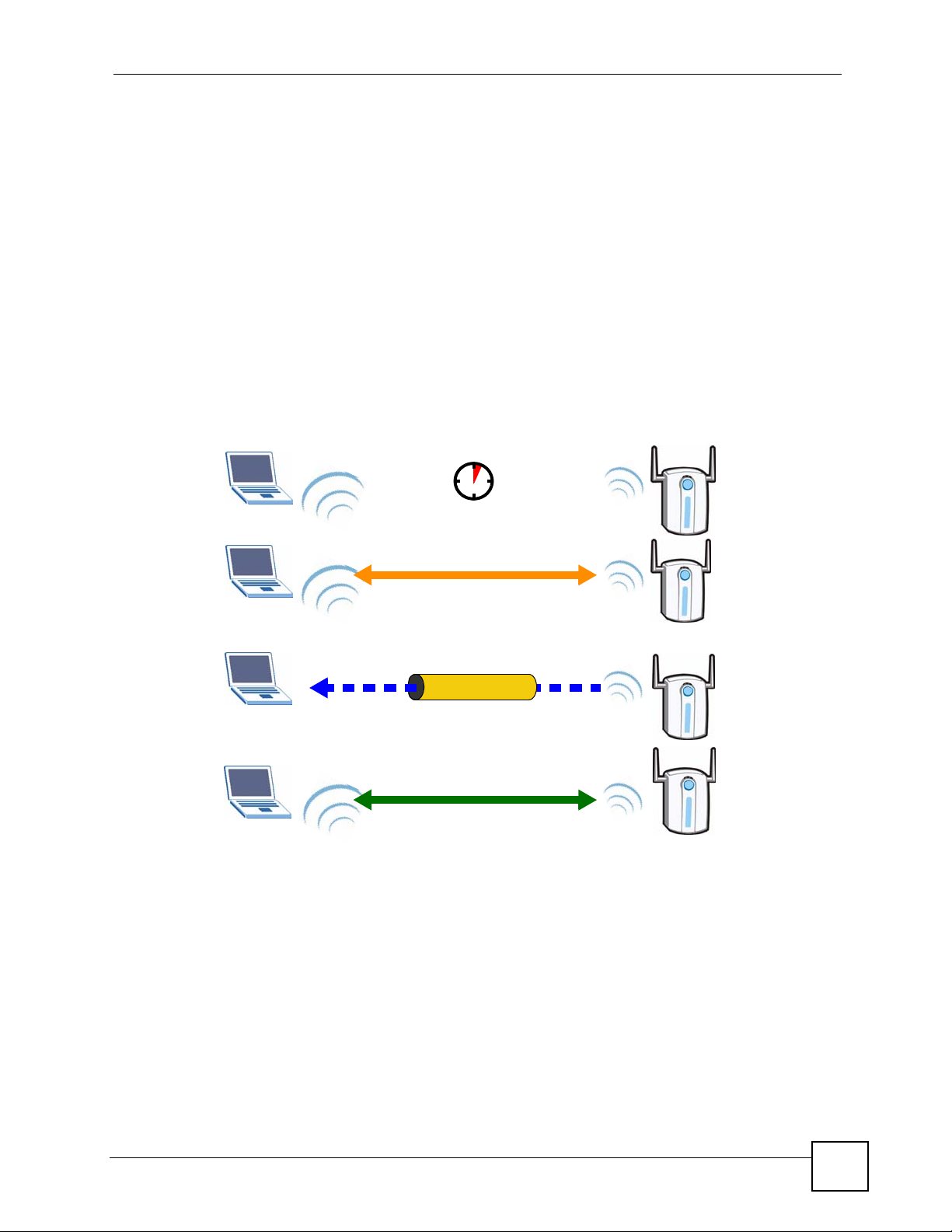
6.5.2 How WPS Works
When two WPS-enabled devices connect, each device must assume a specific role. One device
acts as the registrar (the device that supplies network and security settings) and the other
device acts as the enrollee (the device that receives network and security settings. The registrar
creates a secure EAP (Extensible Authentication Protocol) tunnel and sends the network name
(SSID) and the WPA-PSK or WPA2-PSK pre-shared key to the enrollee. Whether WPA-PSK
or WPA2-PSK is used depends on the standards supported by the devices. If the registrar is
already part of a network, it sends the existing information. If not, it generates the SSID and
WPA(2)-PSK randomly.
The following figure shows a WPS-enabled client (installed in a notebook computer)
connecting to a WPS-enabled access point.
Figure 30 How WPS works
Chapter 6 Wireless LAN
ACTIVATE
WPS
ACTIVATE
WPS
WITHIN 2 MINUTES
WPS HANDSHAKE
REGISTRARENROLLEE
SECURE TUNNEL
SECURITY INFO
COMMUNICATION
The roles of registrar and enrollee last only as long as the WPS setup process is active (two
minutes). The next time you use WPS, a different device can be the registrar if necessary.
The WPS connection process is like a handshake; only two devices participate in each WPS
transaction. If you want to add more devices you should repeat the process with one of the
existing networked devices and the new device.
Note that the access point (AP) is not always the registrar, and the wireless client is not always
the enrollee. All WPS-certified APs can be a registrar, and so can some WPS-enabled wireless
clients.
PLA450 User’s Guide
65
Page 66

Chapter 6 Wireless LAN
By default, a WPS devices is “unconfigured”. This means that it is not part of an existing
network and can act as either enrollee or registrar (if it supports both functions). If the registrar
is unconfigured, the security settings it transmits to the enrollee are randomly-generated. Once
a WPS-enabled device has connected to another device using WPS, it becomes “configured”.
A configured wireless client can still act as enrollee or registrar in subsequent WPS
connections, but a configured access point can no longer act as enrollee. It will be the registrar
in all subsequent WPS connections in which it is involved. If you want a configured AP to act
as an enrollee, you must reset it to its factory defaults.
6.5.2.1 Example WPS Network Setup
This section shows how security settings are distributed in an example WPS setup.
The following figure shows an example network. In step 1, both AP1 and Client 1 are
unconfigured. When WPS is activated on both, they perform the handshake. In this example,
AP1 is the registrar, and Client 1 is the enrollee. The registrar randomly generates the security
information to set up the network, since it is unconfigured and has no existing information.
Figure 31 WPS: Example Network Step 1
REGISTRARENROLLEE
SECURITY INFO
CLIENT 1
AP1
In step 2, you add another wireless client to the network. You know that Client 1 supports
registrar mode, but it is better to use AP1 for the WPS handshake with the new client since
you must connect to the access point anyway in order to use the network. In this case, AP1
must be the registrar, since it is configured (it already has security information for the
network). AP1 supplies the existing security information to Client 2.
Figure 32 WPS: Example Network Step 2
REGISTRAR
EXISTING CONNECTION
CLIENT 1
AP1
O
F
N
I
Y
T
ENROLLEE
I
R
U
C
E
S
66
CLIENT 2
PLA450 User’s Guide
Page 67

Chapter 6 Wireless LAN
In step 3, you add another access point (AP2) to your network. AP2 is out of range of AP1, so
you cannot use AP1 for the WPS handshake with the new access point. However, you know
that Client 2 supports the registrar function, so you use it to perform the WPS handshake
instead.
Figure 33 WPS: Example Network Step 3
EXISTING CONNECTION
N
O
I
CLIENT 1
REGISTRAR
O
C
G
N
I
T
S
I
X
E
T
C
E
N
N
AP1
CLIENT 2
6.5.3 Limitations of WPS
WPS has some limitations of which you should be aware.
• WPS works in Infrastructure networks only (where an AP and a wireless client
communicate). It does not work in Ad-Hoc networks (where there is no AP).
• When you use WPS, it works between two devices only. You cannot enroll multiple
devices simultaneously, you must enroll one after the other.
For instance, if you have two enrollees and one registrar you must set up the first enrollee
(by pressing the WPS button on the registrar and the first enrollee, for example), then
check that it successfully enrolled, then set up the second device in the same way.
• WPS works only with other WPS-enabled devices. However, you can still add non-WPS
devices to a network you already set up using WPS.
WPS works by automatically issuing a randomly-generated WPA-PSK or WPA2-PSK
pre-shared key from the registrar device to the enrollee devices (see Section 6.6.2 on page
70 for information on pre-shared keys). Whether the network uses WPA-PSK or WPA2-
PSK depends on the device. You can check the configuration interface of the registrar
device to discover the key the network is using (if the device supports this feature). Then,
you can enter the key into the non-WPS device and join the network as normal (the nonWPS device must also support WPA-PSK or WPA2-PSK).
S
E
C
U
R
I
T
Y
I
N
F
O
ENROLLEE
AP1
PLA450 User’s Guide
67
Page 68

Chapter 6 Wireless LAN
• When you use the PBC method, there is a short period (from the moment you press the
button on one device to the moment you press the button on the other device) when any
WPS-enabled device could join the network. This is because the registrar has no way of
identifying the “correct” enrollee, and cannot differentiate between your enrollee and a
rogue device. This is a possible way for a hacker to gain access to a network.
6.6 General Wireless LAN Screen
" If you are configuring the PLA450 from a computer connected to the wireless
LAN and you change the PLA450’s SSID, channel or security settings, you will
lose your wireless connection when you press Apply to confirm. You must
then change the wireless settings of your computer to match the PLA450’s
new settings.
Click Network > Wireless LAN to open the General screen.
Figure 34 Network > Wireless LAN > General
The following table describes the general wireless LAN labels in this screen.
Table 12 Network > Wireless LAN > General
LABEL DESCRIPTION
Enable
Wireless LAN
Name(SSID) (Service Set IDentity) The SSID identifies the Service Set with which a wireless
Hide SSID Select this check box to hide the SSID in the outgoing beacon frame so a station
Click the check box to activate wireless LAN.
station is associated. Wireless stations associating to the access point (AP) must
have the same SSID. Enter a descriptive name (up to 32 printable 7-bit ASCII
characters) for the wireless LAN.
cannot obtain the SSID through scanning using a site survey tool.
68
PLA450 User’s Guide
Page 69

Table 12 Network > Wireless LAN > General
LABEL DESCRIPTION
Channel
Selection
Operating
Channel
Apply Click Apply to save your changes back to the PLA450.
Reset Click Reset to reload the previous configuration for this screen.
See the rest of this chapter for information on the other labels in this screen.
6.6.1 No Security
Select No Security to allow wireless stations to communicate with the access points without
any data encryption.
Chapter 6 Wireless LAN
Set the operating frequency/channel depending on your particular region.
Select a channel from the drop-down list box. The options vary depending on the
IEEE 802.11 mode you are using and the country you are in.
Refer to Appendix D on page 159 for more information on channels.
This displays the channel the PLA450 is currently using.
" If you do not enable any wireless security on your PLA450, your network is
accessible to any wireless networking device that is within range.
Figure 35 Network > Wireless LAN > General: No Security
The following table describes the labels in this screen.
Table 13 Wireless No Security
LABEL DESCRIPTION
Security Mode Choose No Security from the drop-down list box.
Apply Click Apply to save your changes back to the PLA450.
Reset Click Reset to reload the previous configuration for this screen.
PLA450 User’s Guide
69
Page 70

Chapter 6 Wireless LAN
6.6.2 WPA-PSK/WPA2-PSK
Click Network > Wireless LAN to display the General screen. Select WPA-PSK or WPA2-
PSK from the Security Mode list.
Figure 36 Network > Wireless LAN > General: WPA-PSK/WPA2-PSK
The following table describes the labels in this screen.
Table 14 Network > Wireless LAN > General: WPA-PSK/WPA2-PSK
LABEL DESCRIPTION
WPA Compatible This check box is available only when you select WPA2-PSK or WPA2 in the
Security Mode field.
Select the check box to have both WPA2 and WPA wireless clients be able to
communicate with the PLA450 even when the PLA450 is using WPA2-PSK or
WPA2.
Pre-Shared Key The encryption mechanisms used for WPA/WPA2 and WPA-PSK/WPA2-PSK
ReAuthentication
Timer (in
seconds)
are the same. The only difference between the two is that WPA-PSK/WPA2-PSK
uses a simple common password, instead of user-specific credentials.
Type a pre-shared key from 8 to 63 case-sensitive ASCII characters (including
spaces and symbols).
Specify how often wireless stations have to resend usernames and passwords in
order to stay connected. Enter a time interval between 10 and 9999 seconds. The
default time interval is 1800 seconds (30 minutes).
Note: If wireless station authentication is done using a RADIUS
server, the reauthentication timer on the RADIUS server has
priority.
Idle Timeout The PLA450 automatically disconnects a wireless station from the wired network
after a period of inactivity. The wireless station needs to enter the username and
password again before access to the wired network is allowed. The default time
interval is 3600 seconds (or 1 hour).
70
PLA450 User’s Guide
Page 71

Table 14 Network > Wireless LAN > General: WPA-PSK/WPA2-PSK
LABEL DESCRIPTION
Group Key
Update Timer
Apply Click Apply to save your changes back to the PLA450.
Reset Click Reset to reload the previous configuration for this screen.
6.7 MAC Filter
The MAC filter screen allows you to configure the PLA450 to give exclusive access to up to
32 devices (Allow) or exclude up to 32 devices from accessing the PLA450 (Deny). Every
Ethernet device has a unique MAC (Media Access Control) address. The MAC address is
assigned at the factory and consists of six pairs of hexadecimal characters, for example,
00:A0:C5:00:00:02. You need to know the MAC address of the devices to configure this
screen.
Chapter 6 Wireless LAN
The Group Key Update Timer is the rate at which the AP (if using WPA-PSK/
WPA2-PSK key management) or RADIUS server (if using WPA/WPA2 key
management) sends a new group key out to all clients. The re-keying process is
the WPA/WPA2 equivalent of automatically changing the WEP key for an AP and
all stations in a WLAN on a periodic basis. Setting of the Group Key Update
Timer is also supported in WPA-PSK/WPA2-PSK mode. The default is 1800
seconds (30 minutes).
To change your PLA450’s MAC filter settings, click Network > Wireless LAN > MAC
Filter. The screen appears as shown.
PLA450 User’s Guide
71
Page 72

Chapter 6 Wireless LAN
Figure 37 Network > Wireless LAN > MAC Filter
The following table describes the labels in this menu.
Table 15 Network > Wireless LAN > MAC Filter
LABEL DESCRIPTION
Active Select Yes from the drop down list box to enable MAC address filtering.
Filter Action Define the filter action for the list of MAC addresses in the MAC Address table.
Select Deny to block access to the PLA450, MAC addresses not listed will be allowed
to access the PLA450
Select Allow to permit access to the PLA450, MAC addresses not listed will be denied
access to the PLA450.
Set This is the index number of the MAC address.
MAC
Address
Apply Click Apply to save your changes back to the PLA450.
Reset Click Reset to reload the previous configuration for this screen.
Enter the MAC addresses of the wireless station that are allowed or denied access to
the PLA450 in these address fields. Enter the MAC addresses in a valid MAC address
format, that is, six hexadecimal character pairs, for example, 12:34:56:78:9a:bc.
6.8 Wireless LAN Advanced Screen
Click Network > Wireless LAN > Advanced. The screen appears as shown.
72
PLA450 User’s Guide
Page 73

Figure 38 Network > Wireless LAN > Advanced
Chapter 6 Wireless LAN
The following table describes the labels in this screen.
Table 16 Network > Wireless LAN > Advanced
LABEL DESCRIPTION
Roaming Configuration
Enable
Roaming
Wireless Advanced Setup
RTS/CTS
Threshold
Fragmentation
Threshold
Enable IntraBSS Traffic
Output Power Set the output power of the PLA450 in this field. If there is a high density of APs
Select this option if your network environment has multiple APs and you want your
wireless device to be able to access the network as you move between wireless
networks.
Data with its frame size larger than this value will perform the RTS (Request To
Send)/CTS (Clear To Send) handshake.
If the RTS/CTS value is greater than the Fragmentation Threshold value, then the
RTS/CTS handshake will never occur as data frames will be fragmented before they
reach RTS/CTS size.
Enter a value between 256 and 2346.
See Appendix D on page 159 for more information.
It is the maximum data fragment size that can be sent. Enter a value between 256
and 2346.
See Appendix D on page 159 for more information.
A Basic Service Set (BSS) exists when all communications between wireless clients
or between a wireless client and a wired network client go through one access point
(AP).
Intra-BSS traffic is traffic between wireless clients in the BSS. When Intra-BSS is
enabled, wireless client A and B can access the wired network and communicate
with each other. When Intra-BSS is disabled, wireless client A and B can still access
the wired network but cannot communicate with each other.
See Appendix D on page 159 for more information.
within an area, decrease the output power of the PLA450 to reduce interference with
other APs.
PLA450 User’s Guide
73
Page 74

Chapter 6 Wireless LAN
Table 16 Network > Wireless LAN > Advanced
LABEL DESCRIPTION
802.11 Mode Select 802.11b to allow only IEEE 802.11b compliant WLAN devices to associate
Super G Mode Use this field to enable or disable the Super G function. Super G mode is available
Apply Click Apply to save your changes back to the PLA450.
Reset Click Reset to reload the previous configuration for this screen.
with the PLA450.
Select 802.11g to allow only IEEE 802.11g compliant WLAN devices to associate
with the PLA450.
Select 802.11b/g to allow either IEEE802.11b or IEEE802.11g compliant WLAN
devices to associate with the PLA450. The transmission rate of your PLA450 might
be reduced.
only if you select 802.11g or 802.11b/g in the 802.11 Mode field.
Super G provides higher data transmission rates than 802.11g.
Select Disabled if your wireless clients do not support Super G.
Select Super G with Dynamic Turbo if some or all of your wireless clients support
Super G with Dynamic Turbo. Dynamic Turbo uses two channels bonded together to
achieve higher transmission rates than 802.11g or Super G without Dynamic Turbo.
Dynamic turbo is on only when all wireless devices on the network support it. The
wireless channel is automatically fixed at 6 if you select this mode.
Select Super G without Turbo if the wireless clients on your network support Super
G but do not support Dynamic Turbo.
6.9 Quality of Service (QoS) Screen
The QoS screen allows you to automatically give a service (such as e-mail, VoIP or FTP) a
priority level.
Click Network > Wireless LAN > QoS. The following screen appears.
74
PLA450 User’s Guide
Page 75

Figure 39 Network > Wireless LAN > QoS
Chapter 6 Wireless LAN
The following table describes the labels in this screen.
Table 17 Network > Wireless LAN > QoS
LABEL DESCRIPTION
Enable WMM QoS Use WMM QoS (Wifi MultiMedia Quality of Service) to give different
types of traffic different priorities. The PLA450 assigns priority to
packets based on the 802.1q or DSCP information in their headers.
If a packet has no WMM information in its header, it is assigned the
default priority. See Section 6.4.1 on page 63 for more information.
WMM QoS Policy Select Default to have the PLA450 automatically give voice and
video traffic priority so their services operate more smoothly. The
PLA450 gives a service a priority level according to the ToS value
in the IP header of packets it sends.
Select Application Priority from the drop-down list box to display a
table of application names, services, ports and priorities to which
you want to apply WMM QoS.
The table appears only if you select Application Priority in WMM
QoS Policy.
# This is the number of an individual application entry.
Name This field displays a description given to an application entry.
Service This field displays either FTP, WWW, E-mail or a User Defined
service to which you want to apply WMM QoS.
Dest Port This field displays the destination port number to which the
application sends traffic.
Priority This field displays the priority of the application.
PLA450 User’s Guide
75
Page 76

Chapter 6 Wireless LAN
Table 17 Network > Wireless LAN > QoS (continued)
LABEL DESCRIPTION
Modify Click the Edit icon to open the Application Priority Configuration
screen. Modify an existing application entry or create a application
entry in the Application Priority Configuration screen.
Click the Remove icon to delete an application entry.
Apply Click Apply to save your changes to the PLA450.
6.9.1 Application Priority Configuration
Use this screen to edit a WMM QoS application entry. Click the edit icon under Modify. The
following screen displays.
Figure 40 Network > Wireless LAN > QoS: Application Priority Configuration
See Appendix E on page 173 for a list of commonly-used services and destination ports. The
following table describes the fields in this screen.
Table 18 Network > Wireless LAN > QoS: Application Priority Configuration
LABEL DESCRIPTION
Application Priority Configuration
Name Type a description of the application priority.
Service The following is a description of the applications you can prioritize with WMM
QoS. Select a service from the drop-down list box.
•User-Defined
User-defined services are user specific services configured using known ports
and applications.
• E-Mail
Electronic mail consists of messages sent through a computer network to
specific groups or individuals. Here are some default ports for e-mail:
POP3 - port 110
IMAP - port 143
SMTP - port 25
HTTP - port 80
•FTP
File Transfer Protocol enables fast transfer of files, including large files that it
may not be possible to send via e-mail. FTP uses port number 21.
•WWW
The World Wide Web is an Internet system to distribute graphical, hyperlinked information, based on Hyper Text Transfer Protocol (HTTP) - a client/
server protocol for the World Wide Web. The Web is not synonymous with the
Internet; rather, it is just one service on the Internet. Other services on the
Internet include Internet Relay Chat and Newsgroups. The Web is accessed
through use of a browser.
76
PLA450 User’s Guide
Page 77

Table 18 Network > Wireless LAN > QoS: Application Priority Configuration (continued)
LABEL DESCRIPTION
Dest Port This displays the port the selected service uses. Type a port number in the
Priority Select a priority from the drop-down list box.
Apply Click Apply to save your changes back to the PLA450.
Cancel Click Cancel to return to the previous screen.
6.10 WPS Screen
Use this screen to enable WiFi Protected Setup (WPS) on your PLA450 and to set up a WPS
connection using a PIN (Personal Identification Number) generated by the PLA450.
Chapter 6 Wireless LAN
field provided if you want to use a different port to the default port.
Highest - Typically used for voice.
High - Typically used for video.
Mid - Typically used for applications that do not fit into another priority. For
example, Internet surfing.
Low - Typically used for non-critical “background” applications, such as large
file transfers and print jobs that should not affect other applications.
See Section 6.5.1 on page 64 for instructions on using WPS with a PIN.
Click Network > Wireless >WPS. The following screen displays.
Figure 41 Network > Wireless LAN > WPS
The following table describes the labels in this screen.
Table 19 Network > Wireless LAN > WPS
LABEL DESCRIPTION
WPS Setup
Enable WPS Use this to turn WiFi Protected Setup on or off.
PIN Number This is the PIN (Personal Identification Number) the PLA450 uses
to authenticate other WPS-enabled wireless devices. The PIN is
not necessary when using WPS’s push-button method.
Enter this PIN in the configuration utility of the device you want to
connect to using WPS. You may need to write this down.
PLA450 User’s Guide
77
Page 78

Chapter 6 Wireless LAN
Table 19 Network > Wireless LAN > WPS
LABEL DESCRIPTION
Generate Click this to have the PLA450 use a different WPS PIN. The new
WPS Status
Status This displays the current WPS configuration status. If no wireless
Apply Click this to save your changes to the PLA450.
Refresh Click this to reload the information in this screen.
6.11 WPS Station Screen
Use this screen to set up a WPS connection using the Push Button Configuration (PBC)
method. You can use the push-button in the screen below or the external push-button on the
side of your device, if it has one. See Section 2.2 on page 35 for instructions on using WPS
using the external WPS button.
PIN is automatically generated. The PLA450 uses the new PIN
once you click Apply.
To connect additional devices to your PLA450 using WPS you can
use the same PIN again or generate a new one for each setup
procedure.
settings (such as security settings) are configured Unconfigured
displays. Once the WPS process is complete, Configured displays
in this field.
You can also use this screen to set up a WPS connection using the PIN of another WPSenabled device. See Section 6.5.1 on page 64 for instructions on using WPS with a PIN.
Click Network > Wireless LAN > WPS Station for the following screen to display.
Figure 42 Network > Wireless LAN > WPS Station
78
PLA450 User’s Guide
Page 79

Chapter 6 Wireless LAN
The following table describes the labels in this screen.
Table 20 Network > Wireless LAN > WPS
LABEL DESCRIPTION
Push Button Click this button to begin the WPS process. You have two minutes
Or input station’s PIN number Type the PIN of the device that you are setting up a WPS
to press the button on the device you wish to connect with. This
button may either be a physical button on the outside of device, or a
menu button similar to the Push Button button on this screen.
connection with. You can find the PIN either on the outside of the
device, or by checking the device’s settings. Click Start to begin the
WPS procedure.
PLA450 User’s Guide
79
Page 80

Chapter 6 Wireless LAN
80
PLA450 User’s Guide
Page 81

CHAPTER 7
LAN
This chapter describes how to configure LAN settings.
7.1 LAN Overview
A Local Area Network (LAN) is a shared communication system to which many computers
are attached. A LAN is a computer network limited to the immediate area, usually the same
building or floor of a building. Use the LAN screen to configure the PLA450’s IP address to
be on your network.
7.1.1 Factory LAN Defaults
The LAN parameters of the PLA450 are preset in the factory with the following values:
• IP address of 192.168.1.2
• subnet mask of 255.255.255.0 (24 bits)
7.1.2 IP Address
Every computer on your network must have a unique IP address. The Internet Assigned
Numbers Authority (IANA) has reserved the following three blocks of IP addresses
specifically for private networks.
Table 21 Private IP Address Ranges
10.0.0.0 - 10.255.255.255
172.16.0.0 - 172.31.255.255
192.168.0.0 - 192.168.255.255
The PLA450’s IP address can be assigned manually (a static or ‘fixed’ IP address) or by a
DHCP server on your network.
" Regardless of your particular situation, do not create an arbitrary IP address;
always follow the guidelines above. For more information on address
assignment, please refer to RFC 1597, Address Allocation for Private Internets
and RFC 1466, Guidelines for Management of IP Address Space.
PLA450 User’s Guide
81
Page 82

Chapter 7 LAN
7.1.3 IP Address and Subnet Mask
Similar to the way houses on a street share a common street name, so too do computers on a
LAN share one common network number.
Where you obtain your network number depends on your particular situation. If the ISP or
your network administrator assigns you a block of registered IP addresses, follow their
instructions in selecting the IP addresses and the subnet mask.
If the ISP did not explicitly give you an IP network number, then most likely you have a single
user account and the ISP will assign you a dynamic IP address when the connection is
established. The Internet Assigned Number Authority (IANA) reserved this block of addresses
specifically for private use; please do not use any other number unless you are told otherwise.
Let's say you select 192.168.1.0 as the network number; which covers 254 individual
addresses, from 192.168.1.1 to 192.168.1.254 (zero and 255 are reserved). In other words, the
first three numbers specify the network number while the last number identifies an individual
computer on that network.
Once you have decided on the network number, pick an IP address that is easy to remember,
for instance, 192.168.1.1, for your PLA450, but make sure that no other device on your
network is using that IP address.
The subnet mask specifies the network number portion of an IP address. Your PLA450 will
compute the subnet mask automatically based on the IP address that you entered. You don't
need to change the subnet mask computed by the PLA450 unless you are instructed to do
otherwise.
7.2 LAN IP Screen
Use this screen to change your PLA450’s IP address. Click Network > LAN.
Figure 43 Network > LAN > IP
The following table describes the labels in this screen.
Table 22 Network > LAN > IP
LABEL DESCRIPTION
LAN TCP/IP
Get from DHCP
Server
Select this option if you have a DHCP server on your network. If you have a
router, it likely includes a DHCP server function.
82
PLA450 User’s Guide
Page 83

Chapter 7 LAN
Table 22 Network > LAN > IP
LABEL DESCRIPTION
User Defined LAN
IP
IP Address Enter the PLA450’s IP address in dotted decimal notation. 192.168.1.2 is the
IP Subnet Mask Enter the IP subnet mask in this field if you have a specific IP address for the
Gateway IP
Address
Apply Click Apply to save your changes back to the PLA450.
Reset Click Reset to begin configuring this screen afresh.
Select this option to use a specific (fixed) IP address.
factory default.
PLA450 to use.
The subnet mask specifies the network number portion of an IP address. Your
PLA450 automatically calculates the subnet mask based on the IP address that
you assign. Unless you are implementing subnetting, use the subnet mask
computed by the PLA450.
Enter a gateway IP address in this field if you have a specific IP address for the
PLA450 to use.
PLA450 User’s Guide
83
Page 84

Chapter 7 LAN
84
PLA450 User’s Guide
Page 85

CHAPTER 8
HomePlug AV
This chapter introduces the main applications and management of the powerline feature.
8.1 Overview
The PLA450 is a HomePlug AV compliant powerline Ethernet adapter. The PLA450 and
other HomePlug AV powerline adapters in your network communicate with each other by
sending and receiving information over your home’s electrical wiring.
The PLA450 plugs into an ordinary outlet to create a new network which can extend to any
other electrical outlet in any room of a house.
The following section shows you a typical application. Computers A and B use HomePlug AV
powerline adapters and the building’s electrical wiring to connect to the PLA450 C and access
the Internet through broadband modem D.
Figure 44 Expand Your Network
D
C
To set up your powerline network do the following.
B
A
1 Connect your PLA450 to the Internet.
PLA450 User’s Guide
85
Page 86

Chapter 8 HomePlug AV
2 Then plug your PLA450 into a power outlet.
The PLA450 is ready for connection on a powerline network.
3 Connect another HomePlug AV compatible adapter to a computer and then plug it in on
the same home or office wiring.
After configuring the settings on all adapters (see Section 8.3 on page 88) your computer can
now connect to the powerline network and to the Internet. Your powerline network can be
further expanded by plugging additional powerline adapters into other outlets in your home
and connecting other computers or network devices (for example, a printer) to them.
In this User’s Guide the electrical wiring network may be referred to as the “powerline
network”.
" Your PLA450 is only compatible with ZyXEL HomePlug AV products with the
latest firmware. You can upgrade your other ZyXEL HomePlug AV products by
downloading the latest firmware from the ZyXEL website (www.zyxel.com).
8.2 Privacy and Powerline Adapters
When the PLA450 communicates with each other HomePlug AV compliant powerline
adapters, they use encryption to scramble the information that is sent in the powerline
network. Encryption is like a secret code. If you do not know the secret code, you cannot
understand the message. The HomePlug AV standard uses 128-bit AES (Advanced
Encryption Standard) to safely transmit data between powerline adapters.
For the PLA450 and powerline adapters to communicate with each other they all need to use
the same Network Membership Key (NMK). Otherwise, they cannot unscramble the
encrypted data sent in the powerline network.
The NMK is derived from the network name (password) you assign to the
powerline adapters. By default all HomePlug powerline adapters are configured with the
network password HomePlugAV. This allows all HomePlug powerline adapters and the
PLA450 to communicate with each other without any software configuration. This also means
that if you don’t change the network password, any HomePlug AV powerline adapter
connected to your powerline circuit can see your network data.
PLA450 and
" Change the network password on your powerline adapters to ensure secure
data transmission on your powerline network.
86
PLA450 User’s Guide
Page 87

8.2.1 Setting Up a Private Powerline Network
To prevent others compromising your network security, you can create a private network.
Create a private network by changing the network password only on the powerline adapters
you want to communicate in your network. Only the powerline adapters with the same
network password can communicate in your network.
The following figure shows a scenario A - where all the powerline adapters have the same
network password (1) and scenario B - where some adapters use password 1 and some use
password 2.
Figure 45 Powerline Network Scenario
AB
1
1
1
1
1
1
Chapter 8 HomePlug AV
2
2
1
In both cases the powerline adapters reside on the same electrical circuit. In scenario A all the
powerline adapters can communicate with each other. In scenario B only the adapters with the
same password can receive and unscramble communication between each other.
1
1
8.2.2 Setting Up Multiple Powerline Networks.
Multiple powerline networks can coexist on a single powerline circuit. You might want to
implement multiple powerline networks in a small office environment where you have two
separate Ethernet networks.
Connect one powerline adapter to a router or switch on the first Ethernet network and assign a
network password (for example, “Password1”) to this powerline adapter. Add additional
powerline adapters to your network by plugging them into your powerline outlets and
assigning them the same network password, “Password1”. This completes the configuration of
your first powerline network.
Connect another powerline adapter to a router or switch on the second Ethernet network and
assign a different network password (for example “Password2”) to this powerline adapter.
Again, add additional powerline adapters and assign them the same second network password,
“Password2”.
You now have two private networks on your powerline circuit. Information is not shared
between the two networks as only powerline adapters with the same password can
communicate with each other. The following figure shows two private powerline networks on
the same electrical circuit.
2
PLA450 User’s Guide
87
Page 88

Chapter 8 HomePlug AV
Figure 46 Two Private Powerline Networks on One Circuit
Password 1
Password 1
Password 2
Password 2
8.3 Configuring Your HomePlug AV Devices
Click on Network > HomePlug to see the screen below. Use this screen to set up a HomePlug
AV network and to check the status of HomePlug AV devices on your electrical circuit.
88
PLA450 User’s Guide
Page 89

Figure 47 Network > HomePlug > Network Settings
Chapter 8 HomePlug AV
The following table describes the labels in the screen.
Table 23 Network > HomePlug > Network Settings
LABEL DESCRIPTION
Network Name This section lets you set the name of your network and to make it either public or
private.
The Network Name performs the same function as a network password. All
devices on your HomePlug network have the same Network Name. A device
with a different Network Name cannot be on your network.
You can add other HomePlugAV devices to your network by giving them the
same Network Name.
Network Type The network may be either public or private.
Public, Network
Name is HomePlug
AV
Private, Network
Name is
Set Click Set to change the Network Name of all the devices currently in your
Add New Member This section lets you add new Home Plug AV enabled devices to your powerline
Device Information In this section type information to identify the new powerline device you are
Nickname Type a name you wish to use to identify a specific powerline adapter, for
MAC Address Type the MAC address of the adapter you wish to add. The MAC address of your
Select this option if you want to make your powerline network public with the
default Network Name of “HomePlug AV”. Since this is well known, it is less
secure than a private network name.
Select this option if you wish to make your powerline network more secure with a
private Network Name. Type the name of your private powerline network in the
field. You may enter up to 64 alphanumeric characters for the Network Name.
network.
network. When you add the device it is given the current Network Name.
adding on your network.
example, “Mary’s room”.
powerline adapter can be found by looking at the label on your device. It consists
of six pairs of hexadecimal characters (hexadecimal characters are “0-9” and “af”). In the case of the PLA450, this label is on the bottom of the device.
PLA450 User’s Guide
89
Page 90

Chapter 8 HomePlug AV
Table 23 Network > HomePlug > Network Settings
LABEL DESCRIPTION
DAK Password The DAK Password (DAK stands for Device Access Key), is used to verify that
My Homeplug
Network
Nickname This is the nickname you gave to the HomePlug AV device.
MAC Address This is the MAC address of the HomePlug AV device.
Status This field shows the status of the device.
Member Action This field shows the Add, Edit and Delete icons. Click Add to add a device to
Scan Click Scan to detect devices on the same electrical circuit as the PLA450.
you are authorized to perform changes on a device. You can find the DAK
printed on a sticker on the bottom of a HomePlug enabled device.
This section provides information on the HomePlug AV devices in your network
(or that were previously connected on it but are currently disconnected).
Active: the device is connected to your network.
Out of Network: the device has been added to the network but it is not ready.
Check whether it is turned on and connected.
Not member: the device is not on the network. The PLA450 is aware of it, but
cannot manage the device. If you click Set, the device’s Network Name will not
change. You can add it to the network by clicking on Edit or entering its details in
the Add New member section.
the network . Click Edit to edit a device’s details such as the device’s Nickname.
Click Delete to remove the device from the network.
If you want to set up a second network, remove the devices from My HomePlug
Network that you want to keep in your first network before you set the new
Network Name for the second network.
Click Network > HomePlug > Edit to see the screen below. Use this screen to add a new
HomePlug AV device to the network. You can also edit a device’s details.
Figure 48 Network > HomePlug > Edit
The following table describes the labels in the screen.
Table 24 Network > HomePlug > Edit
LABEL DESCRIPTION
Device Information
Nickname Type a name you wish to use to identify a specific powerline adapter, for
example, “Bob’s room”.
MAC Address This is the MAC address of the HomePlug AV device. The MAC Address will
appear in this field if the device’s status is either Active or Not Member. If the
device’s status is Out of Network or your PLA450 can not detect it, type the
MAC Address here.
90
PLA450 User’s Guide
Page 91

Table 24 Network > HomePlug > Edit
LABEL DESCRIPTION
DAK Password The DAK Password (DAK stands for Device Access Key), is used to verify that
you are authorized to perform changes on a device. You can find the DAK
printed on a sticker on the bottom of a HomePlug enabled device.
Apply Click this button to apply add the device to the network or to apply your changes.
Cancel Click this button to return to the previous screen.
8.4 HomePlug AV QoS
Your PLA450 can send different kinds of traffic through your powerline network at different
speeds depending on the priority you give it. This feature is called Quality of Service (QoS).
• You can configure your PLA450 to give priority to powerline network traffic depending
on its destination (MAC Address or IP Port Number Priority).
• You can also map the priority settings (VLAN or ToS priority settings) of traffic from
outside your powerline network to priority settings for your powerline network (Priority
Mapping).
• Priority can also be assigned according to traffic type such as IGMP (Default Priority).
Chapter 8 HomePlug AV
Powerline traffic priority can be set at Highest, High, Mid and Low. The following priority
settings are guidelines. The requirements of your powerline network may differ.
Table 25 Priority Settings
PRIORITY LEVEL APPLICATION
Highest Voice Application
High Video and Audio Applications
Mid Data Applications
Low Data Applications
8.4.1 QoS Based on IP or MAC Address
You can prioritize traffic passing through your PLA450 based on the device it is intended for.
Do this by setting the MAC address or IP address of a device(s) on your network and the level
of priority of network traffic going to that device.
For example, if you have a digital media adapter such as the DMA-1100P on your network set
up to play movie files on your T.V., you can set this device to High. This is because if video or
music traffic is delivered too slowly, quality problems may occur.
8.4.2 Mapping other QoS Priority Settings to HomePlug AV QoS
Wired networks use QoS priority settings such as VLAN priority settings or ToS (Type of
Service) settings to help network traffic flow more smoothly. However, powerline devices
cannot use these priority settings unless they are mapped over to HomePlug AV QoS priority
settings.
(VLAN priority settings are not to be confused with VLAN ID. The VLAN tag contains both
priority settings (0~7) and ID information (1~4095).)
PLA450 User’s Guide
91
Page 92

Chapter 8 HomePlug AV
For example, your ISP (A) may use VLAN priority settings to identify and prioritize VoIP
(Voice over IP) traffic or you may have a VoIP device (B) attached to your PLA450 which
adds ToS (Type of Service) priorities to data it sends. By giving high priority to VoIP traffic in
your powerline network, VoIP traffic flows more smoothly.
Figure 49 Prioritized Traffic Between Your Home Powerline Network and the Internet
Internet
A
B
The following mappings are suggestions only. VLAN and ToS priority settings may not map
exactly to Homeplug AV priority settings. Priority settings for VLAN Tags and ToS bits range
from 0 to 7 with 7 as the highest.
Table 26 Suggested Mappings
VLAN/TOS PRIORITY
SETTINGS
5~7 Highest
4 High
2~3 Mid
0~1 Low
HOMEPLUG AV
PRIORITY SETTINGS
8.4.3 QoS Based on Traffic Type
You can prioritize traffic on your powerline network based on four kinds of traffic types.
These are IGMP, IGMP managed Multicast Stream, Unicast and Multicast/Broadcast.
However, it is recommended that you do not change the default settings.
Unicast and Multicast/Broadcast refer to how IP packets are transmitted. Unicast
transmission is from one sender to one recipient. Broadcast transmission is from one sender to
all devices on a network. Multicast transmission is from one sender to some of the devices on
the network.
92
PLA450 User’s Guide
Page 93

Chapter 8 HomePlug AV
IGMP (Internet Group Membership Protocol) is a network protocol which lets devices on a
network join or leave a multicast group. An IGMP managed Multicast Stream refers to
streaming media (such as video or audio) to a group of devices on a network using IGMP to
manage the multicast.
IGMP is assigned highest priority as it controls multicast services such as IGMP managed
Multicast Stream which allows streamed traffic such as video or VoIP. Unicast, Multicast/
Broadcast require less priority than the traffic that manages them.
Select Network > HomePlug > QoS to set levels of service for different kinds of traffic on
your powerline connection. The following screen displays
Figure 50 Network > HomePlug > QoS.
PLA450 User’s Guide
93
Page 94

Chapter 8 HomePlug AV
The following table describes the labels in the screen.
Table 27 Network > HomePlug > Edit
LABEL DESCRIPTION
MAC Address or IP Port Number Priority
Number This is the index number for a priority rule.
Rule Name Type a descriptive name for a priority rule. You can enter up to 31 characters
MAC Address
or IP Port
Number
Priority Select the priority level for this rule. The options are Highest, High, Mid and
Modify Click the modify icon to remove the rule.
Priority Mapping
Assign Priority
Using
Value VLAN priority settings and ToS bits priority settings range from 0 to 7 with 7 as
Priority Assign a priority setting to packets passing through your PLA450 based on their
Default Priority
Traffic Type This option applies priority settings to traffic based on its traffic type. You can
Apply Click Apply to save your settings.
containing “0”~”9”, “a”~”z”, “A”~”Z”, “_” or -. Spaces are allowed.
Type the MAC (Media Access Control) address or IP address of a device on
your network. Network traffic to this device is prioritized according to the priority
level of this rule.
Enter the MAC address using six pairs of hexadecimal characters, for example,
00:A0:C5:00:00:02.
Enter the IP address in dotted decimal notation, for example, 192.168.1.1.
Low.
Use this section to enable or disable priority rules based on VLAN priority
settings or ToS bits.
Select None if you are not prioritizing traffic based on VLAN priority settings or
ToS bits.
Select Support VLAN Tags to map VLAN priority settings to powerline priority
settings. For example, ISPs often assign VLAN tags to traffic based on customer
contracts or traffic type. Selecting this option supports ISP assigned priority
settings.
• VLAN priority settings are not to be confused with VLAN ID. The VLAN tag
contains both priority settings (0~7) and ID information (1~4095).
Select Support TOS Bits to map ToS settings to powerline priority settings. Do
this if you receive network traffic which has been assigned ToS (Type of Service)
bits by the device or application that generated it, or by an intermediate device.
For example, a VoIP device on your network may assign priority to the traffic it
has generated. Selecting this option supports the priority settings such a device
may have assigned.
the highest priority.
VLAN tag or ToS bit priority setting. The options are Highest, High, Mid and
Low. Use Figure 26 on page 92 as a guide if you are unsure of what mappings
to assign.
prioritize IGMP, Unicast, IGMP managed Multicast Stream or Multicast/
Broadcast network traffic. However, it is recommended that you do not change
the default settings.
94
PLA450 User’s Guide
Page 95

PART III
Maintenance and
Troubleshooting
System (97)
Logs (101)
Tools (105)
Configuration Mode (111)
Language (113)
Troubleshooting (115)
Product Specifications and Wall-Mounting Instructions (123)
95
Page 96

96
Page 97

CHAPTER 9
System
This chapter provides information on the System screens.
9.1 System General Screen
Click Maintenance > System. The following screen displays.
Figure 51 Maintenance > System > General
The following table describes the labels in this screen.
Table 28 Maintenance > System > General
LABEL DESCRIPTION
System Name The system name is a unique name to identify the PLA450 in an Ethernet
Domain Name Enter the domain name (if you know it) here. If you leave this field blank, your
Administrator
Inactivity Timer
PLA450 User’s Guide
network.
This name can be up to 30 alphanumeric characters long. Spaces are not
allowed, but dashes “-” and underscores "_" are accepted.
DHCP server may assign a domain name.
The domain name entered by you is given priority over a DHCP-assigned
domain name.
Type how many minutes a management session can be left idle before the
session times out. The default is 5 minutes. After it times out you have to log in
with your password again. Very long idle timeouts may have security risks. A
value of "0" means a management session never times out, no matter how long it
has been left idle (not recommended).
97
Page 98

Chapter 9 System
Table 28 Maintenance > System > General
LABEL DESCRIPTION
Password Setup Change your PLA450’s password (recommended) using the fields as shown.
Old Password Type the default password or the existing password you use to access the
New Password Type your new system password (up to 30 characters). Note that as you type a
Retype to Confirm Type the new password again in this field.
Apply Click Apply to save your changes back to the PLA450.
Reset Click Reset to begin configuring this screen afresh.
system in this field.
password, the screen displays an asterisk (*) for each character you type.
9.2 Time Setting Screen
To change your PLA450’s time and date, click Maintenance > System > Time Setting. The
screen appears as shown. Use this screen to configure the PLA450’s time based on your local
time zone.
Figure 52 Maintenance > System > Time Setting
98
PLA450 User’s Guide
Page 99

Chapter 9 System
The following table describes the labels in this screen.
Table 29 Maintenance > System > Time Setting
LABEL DESCRIPTION
Current Time and
Date
Current Time This field displays the time of your PLA450.
Each time you reload this page, the PLA450 synchronizes the time with the time
server.
Current Date This field displays the date of your PLA450.
Each time you reload this page, the PLA450 synchronizes the date with the time
server.
Time and Date
Setup
Manual Select this radio button to enter the time and date manually. If you configure a
new time and date, Time Zone and Daylight Saving at the same time, the new
time and date you entered has priority and the Time Zone and Daylight Saving
settings do not affect it.
When you enter the time settings manually, the PLA450 uses the new setting
once you click Apply.
Note: If you enter time settings manually, they revert to their
defaults when power is lost.
New Time
(hh:mm:ss)
New Date
(yyyy/mm/dd)
Get from Time
Server
Auto Select Auto to have the PLA450 automatically search for an available time
User Defined Time
Server Address
Time Zone Setup
Time Zone Choose the time zone of your location. This will set the time difference between
Daylight Savings Daylight Saving Time is a period from late spring to early fall when many
This field displays the last updated time from the time server or the last time
configured manually.
When you set Time and Date Setup to Manual, enter the new time in this field
and then click Apply.
This field displays the last updated date from the time server or the last date
configured manually.
When you set Time and Date Setup to Manual, enter the new date in this field
and then click Apply.
Select this radio button to have the PLA450 get the time and date from the time
server you specified below.
server and synchronize the date and time with the time server after you click
Apply.
Select User Defined Time Server Address and enter the IP address or URL
(up to 20 extended ASCII characters in length) of your time server. Check with
your ISP/network administrator if you are unsure of this information.
your time zone and Greenwich Mean Time (GMT).
countries set their clocks ahead of normal local time by one hour to give more
daytime light in the evening.
Select this option if you use Daylight Saving Time.
PLA450 User’s Guide
99
Page 100

Chapter 9 System
Table 29 Maintenance > System > Time Setting
LABEL DESCRIPTION
Start Date Configure the day and time when Daylight Saving Time starts if you selected
End Date Configure the day and time when Daylight Saving Time ends if you selected
Apply Click Apply to save your changes back to the PLA450.
Reset Click Reset to begin configuring this screen afresh.
Daylight Savings. The o'clock field uses the 24 hour format. Here are a
couple of examples:
Daylight Saving Time starts in most parts of the United States on the second
Sunday of March. Each time zone in the United States starts using Daylight
Saving Time at 2 A.M. local time. So in the United States you would select
Second, Sunday, March and 2:00.
Daylight Saving Time starts in the European Union on the last Sunday of March.
All of the time zones in the European Union start using Daylight Saving Time at
the same moment (1 A.M. GMT or UTC). So in the European Union you would
select Last, Sunday, March. The time you type in the o'clock field depends on
your time zone. In Germany for instance, you would type 2 because Germany's
time zone is one hour ahead of GMT or UTC (GMT+1).
Daylight Savings. The o'clock field uses the 24 hour format. Here are a
couple of examples:
Daylight Saving Time ends in the United States on the first Sunday of
November. Each time zone in the United States stops using Daylight Saving
Time at 2 A.M. local time. So in the United States you would select First,
Sunday, November and 2:00.
Daylight Saving Time ends in the European Union on the last Sunday of
October. All of the time zones in the European Union stop using Daylight Saving
Time at the same moment (1 A.M. GMT or UTC). So in the European Union you
would select Last, Sunday, October. The time you type in the o'clock field
depends on your time zone. In Germany for instance, you would type 2 because
Germany's time zone is one hour ahead of GMT or UTC (GMT+1).
100
PLA450 User’s Guide
 Loading...