

Page 1

PES-1014
Phoneline-Ethernet Switch
Version 1.14
November 2001
User’s Guide
Page 2

PES-1014 User’s Guide
Copyright
Copyright © 2001 by ZyXEL Communications Corporation.
The contents of this publication may not be reproduced in any part or as a whole, transcribed, stored in a retrieval
system, translated into any language, or transmitted in any form or by any means, electronic, mechanical,
magnetic, optical, chemical, photocopying, manual, or otherwise, without the prior written permission of ZyXEL
Communications Corporation.
Published by ZyXEL Communications Corporation. All rights reserved.
Disclaimer
ZyXEL does not assume any liability arising out of the application or use of any products, or software described
herein. Neither does it convey any license under its patent rights nor the patent rights of others. ZyXEL further
reserves the right to make changes in any products described herein without notice. This publication is subject to
change without notice.
Trademarks
Trademarks mentioned in this publication are used for identification purposes only and may be properties of their
respective owners.
ii Copyright
Page 3

PES-1014 User’s Guide
ZyXEL Limited Warranty
ZyXEL warrants to the original end user (purchaser) that this product is free from any defects in materials or
workmanship for a period of up to two (2) years from the date of purchase. During the warranty period, and upon
proof of purchase, should the product have indications of failure due to faulty workmanship and/or materials, ZyXEL
will, at its discretion, repair or replace the defective products or components without charge for either parts or labor,
and to whatever extent it shall deem necessary to restore the product or components to proper operating condition.
Any replacement will consist of a new or re-manufactured functionally equivalent product of equal value, and will be
solely at the discretion of ZyXEL. This warranty shall not apply if the product is modified, misused, tampered with,
damaged by an act of God, or subjected to abnormal working conditions.
Note
Repair or replacement, as provided under this warranty, is the exclusive remedy of the purchaser. This warranty is
in lieu of all other warranties, express or implied, including any implied warranty of merchantability or fitness for a
particular use or purpose. ZyXEL shall in no event be held liable for indirect or consequential damages of any kind
of character to the purchaser.
To obtain the services of this warranty, contact ZyXEL's Service Center; refer to the separate Warranty Card for
your Return Material Authorization number (RMA). Products must be returned Postage Prepaid. It is recommended
that the unit be insured when shipped. Any returned products without proof of purchase or those with an out-dated
warranty will be repaired or replaced (at the discretion of ZyXEL) and the customer will be billed for parts and labor.
All repaired or replaced products will be shipped by ZyXEL to the corresponding return address, Postage Paid
(USA and territories only). If the customer desires some other return destination beyond the U.S. borders, the
customer shall bear the cost of the return shipment. This warranty gives you specific legal rights, and you may also
have other rights which vary from state to state.
ZyXEL Limited Warranty iii
Page 4

PES-1014 User’s Guide
Interference Statements and Warnings
FCC
Interference Statement:
This device complies with Part 15 of the FCC rules. Operation is subject to the following two conditions:
(1) This device may not cause harmful interference.
(2) This device must accept any interference received, including interference that may cause undesired operations.
FCC Warning!
This equipment has been tested and found to comply with the limits for a Class A digital device, pursuant to Part 15
of the FCC Rules. These limits are designed to provide reasonable protection against harmful interference in a
commercial environment. This equipment generates, uses, and can radiate radio frequency energy and, if not
installed and used in accordance with the instruction manual, may cause harmful interference to radio
communications. Operation of this equipment in a residential area is likely to cause harmful interference in which
case the user will be required to correct the interfer ence at his own expense.
CE Mark Warning:
This is a class A product. In a domestic environment this product may cause radio interference in which case the
user may be required to take adequate measures.
Certifications
Refer to the product page at www.zyxel.com.
iv Interference Statements and Warnings
Page 5

PES-1014 User’s Guide
Customer Support
If you have questions about your ZyXEL product or desire assistance, contact ZyXEL Communications
Corporation offices worldwide, in one of the following ways:
Contacting Customer Support
When you contact your customer support representative, have the following information ready:
♦ Product model and serial number.
♦ Firmware version information.
♦ Warranty information.
♦ Date you received your product.
♦ Brief description of the problem and the steps you took to solve it.
METHOD
LOCATION
Worldwide
America
Austria
Germany
Malaysia
E-MAIL - SUPPORT/
SALES
support@zyxel.com.tw
support@europe.zyxel.com
sales@zyxel.com.tw +886-3-578-2439 ftp.europe.zyxel.co
support@zyxel.com +1-714-632-0882
sales@zyxel.com +1-714-632-0858 ftp.zyxel.com
support@zyxel.dk +45-3955-0700 www.zyxel.dkScandinavia
sales@zyxel.dk +45-3955-0707 ftp.zyxel.dk
support@zyxel.at +43-1-4948677-0
sales@zyxel.at +43-1-4948678
support@zyxel.de +49-2405-6909-0
sales@zyxel.de +49-2405-6909-99
support@zyxel.com.my
sales@zyxel.com.my +603-795-34-407
TELEPHONE/FAX WEB SITE/ FTP
SITE
+886-3-578-3942 www.zyxel.com
www.europe.zyxel.
com
m
www.zyxel.comNorth
800-255-4101
www.zyxel.at
ftp.zyxel.at
www.zyxel.de
+603-795-44-688
www.zyxel.com.my
REGULAR MAIL
ZyXEL Communications
Corp., 6 Innovation Road II,
Science-Based Industrial
Park, HsinChu, Taiwan 300,
R.O.C.
ZyXEL Communications Inc.,
1650 Miraloma Avenue,
Placentia, CA 92870, U.S.A.
ZyXEL Communications A/S,
Columbusvej 5, 2860
Soeborg, Denmark.
ZyXEL Communications
Services GmbH.
Thaliastrasse 125a/2/2/4 A1160 Vienna, Austria
ZyXEL Deutschland GmbH.
Adenauerstr. 20/A4 D-52146
Wuerselen, Germany
Lot B2-06, PJ Industrial Park,
Section 13, Jalan Kemajuan,
46200 Petaling Jaya Selangor
Darul Ehasn, Malaysia
Customer Support v
Page 6

PES-1014 User’s Guide
Table of Contents
Copyright.......................................................................................................................................................................................ii
ZyXEL Limited Warranty............................................................................................................................................................. iii
Interference Statements and Warnings..................................................................................................................................... iv
Customer Support........................................................................................................................................................................ v
Table of Contents........................................................................................................................................................................vi
List of Figures.............................................................................................................................................................................. ix
List of Tables ............................................................................................................................................................................... xi
Preface ........................................................................................................................................................................................ xii
Chapter 1 Getting to Know the PES-1014...........................................................................................................................1-1
1.1 PES-1014 Phoneline Ethernet Switc h...........................................................................................................1-1
1.2 Features.........................................................................................................................................................1-1
1.2.1 Easy Management .................................................................................................................................1-1
1.2.2 Interface.................................................................................................................................................1-1
1.2.3 High Performance..................................................................................................................................1-1
1.2.4 VLAN Group.........................................................................................................................................1-1
1.2.5 Security Mode.......................................................................................................................................1-2
1.2.6 Loop Free Network................................................................................................................................1-2
1.2.7 Flow control ..........................................................................................................................................1-2
1.2.8 QoS........................................................................................................................................................1-2
1.2.9 Broadcast Storm Control.......................................................................................................................1-2
1.2.10 Firmware Upgrade.............................................................................................................................1-2
1.2.11 LED Indicators..................................................................................................................................1-2
1.3 Physical Specifications ..................................................................................................................................1-2
1.3.1 Dimensions and Weight........................................................................................................................1-2
1.3.2 Operating Environment and Power.......................................................................................................1-3
1.4 MTU Application ............................................................................................................................................1-3
Chapter 2 Hardware Overview .............................................................................................................................................2-1
2.1 Front Panel....................................................................................................................................................2-1
2.1.1 Front Panel Ports...................................................................................................................................2-1
2.1.2 Front Panel LEDs..................................................................................................................................2-1
2.2 Console Port..................................................................................................................................................2-2
2.3 Ethernet Port Connections ............................................................................................................................2-2
2.4 Phoneline Networking Port Connections.......................................................................................................2-2
2.4.1 MDF Connections .................................................................................................................................2-3
2.5 Rear Panel.....................................................................................................................................................2-4
Chapter 3 Getting Started..................................................................................................................................................... 3-1
vi Table of Contents
Page 7

PES-1014 User’s Guide
3.1 Port Naming...................................................................................................................................................3-1
3.2 Web Browser.................................................................................................................................................3-1
3.3 Login..............................................................................................................................................................3-1
3.4 Welcome Screen...........................................................................................................................................3-2
3.5 Main Screen ..................................................................................................................................................3-3
3.5.1 Information Panel.................................................................................................................................. 3-3
3.5.2 Front Panel............................................................................................................................................3-4
3.5.3 System Info...........................................................................................................................................3-5
3.5.4 Saving Changes.....................................................................................................................................3-6
3.5.5 Reset......................................................................................................................................................3-6
Chapter 4 System..................................................................................................................................................................4-1
4.1 Introduction....................................................................................................................................................4-1
4.2 System Info....................................................................................................................................................4-2
4.3 System Configuration....................................................................................................................................4-3
4.4 Port Monitoring Configuration........................................................................................................................4-4
4.5 Networking.....................................................................................................................................................4-5
4.6 SNMP............................................................................................................................................................4-6
4.6.1 SNMP Community................................................................................................................................ 4-6
4.6.2 SNMP Host ........................................................................................................................................... 4-7
4.7 Save Changes...............................................................................................................................................4-8
4.8 Firmware Upgrade.........................................................................................................................................4-8
Chapter 5 Port........................................................................................................................................................................5-1
5.1 Introduction....................................................................................................................................................5-1
5.2 All Ports Status..............................................................................................................................................5-2
5.3 Port Configuration.......................................................................................................................................... 5-3
5.4 Port Assigned................................................................................................................................................5-4
Chapter 6 Trunk.....................................................................................................................................................................6-1
6.1 Introduction....................................................................................................................................................6-1
6.2 Load-balancing Methods...............................................................................................................................6-1
6.2.1 MAC-based Load-balancing.................................................................................................................6-1
6.2.2 Port-based Load-balancing....................................................................................................................6-1
6.3 Trunk Menus.................................................................................................................................................. 6-1
6.3.1 Current Trunk Status............................................................................................................................. 6-2
6.3.2 Load Balancing Method Selection........................................................................................................ 6-2
6.3.3 MAC-based Mode Trunk Configuration...............................................................................................6-3
6.3.4 Port-based Mode Trunk Configuration................................................................................................. 6-4
6.3.5 Port-based Mode Port Mapping...........................................................................................................6-5
Chapter 7 VLAN.....................................................................................................................................................................7-1
Table of Contents vii
Page 8

PES-1014 User’s Guide
7.1 Introduction....................................................................................................................................................7-1
7.1.1 VLAN Status.........................................................................................................................................7-1
7.2 Edit VLAN Group ...........................................................................................................................................7-2
Chapter 8 Forwarding DB (Database)..................................................................................................................................8-1
8.1 Introduction....................................................................................................................................................8-1
8.2 Current Forwarding DB Status ......................................................................................................................8-1
8.2.1 Current Static Entries............................................................................................................................8-2
8.2.2 Edit Static Entry ....................................................................................................................................8-3
Chapter 9 Statistics...............................................................................................................................................................9-1
9.1 Introduction....................................................................................................................................................9-1
9.2 TX/RX Counters.............................................................................................................................................9-2
9.3 Error Counters...............................................................................................................................................9-3
9.4 Packet Analysis (TX) .....................................................................................................................................9-4
9.5 Packet Analysis (RX).....................................................................................................................................9-5
9.6 Packet Attribute .............................................................................................................................................9-6
9.7 Collision Info ..................................................................................................................................................9-7
9.7.1 Single Port Statistics..............................................................................................................................9-8
Chapter 10 STP......................................................................................................................................................................10-1
10.1 Introduction..............................................................................................................................................10-1
10.2 Spanning Tree Configuration (Bridge) – (Switch Parameters)................................................................10-1
10.3 Spanning Tree Configuration (Port).........................................................................................................10-3
Chapter 11 Reset...................................................................................................................................................................11-1
11.1 Introduction..............................................................................................................................................11-1
11.2 Reset Counters........................................................................................................................................11-1
11.3 Reset To Factory Default.........................................................................................................................11-2
11.4 Reboot Device......................................................................................................................................... 11-2
Chapter 12 Account ..............................................................................................................................................................12-1
12.1 Introduction..............................................................................................................................................12-1
12.2 Browse Account List ................................................................................................................................12-1
12.3 Add/Del Account......................................................................................................................................12-2
12.4 Change Pass word ...................................................................................................................................12-3
Appendix A System Parameters................................................................................................................................................A
Appendix B Safety Warnings and Instructions..........................................................................................................................E
Index..............................................................................................................................................................................................G
viii Table of Contents
Page 9

PES-1014 User’s Guide
List of Figures
Figure 1-1 MTU Application.......................................................................................................................................................1-3
Figure 2-1 PES-1014 Front Panel................................................................................................................................................2-1
Figure 2-2 Phoneline Port Connections.......................................................................................................................................2-3
Figure 2-3 MDF-2 Connections..................................................................................................................................................2-3
Figure 2-4 PES-1014 Rear Panel.................................................................................................................................................2-4
Figure 3-1 Login..........................................................................................................................................................................3-1
Figure 3-2 Welcome Screen ........................................................................................................................................................3-2
Figure 3-3 Main Screen...............................................................................................................................................................3-3
Figure 3-4....................................................................................................................................................................................3-3
Figure 3-5....................................................................................................................................................................................3-3
Figure 3-6....................................................................................................................................................................................3-3
Figure 3-7 Information Panel......................................................................................................................................................3-3
Figure 3-8 Switch Icon................................................................................................................................................................3-4
Figure 3-9 Front Panel.................................................................................................................................................................3-4
Figure 3-10 System Info..............................................................................................................................................................3-5
Figure 4-1 System .......................................................................................................................................................................4-1
Figure 4-2 System Info................................................................................................................................................................4-2
Figure 4-3 System Configuration................................................................................................................................................4-3
Figure 4-4 Port Monitoring Configuration..................................................................................................................................4-4
Figure 4-5 Networking................................................................................................................................................................4-5
Figure 4-6 SNMP Community....................................................................................................................................................4-6
Figure 4-7 SNMP Host................................................................................................................................................................4-7
Figure 4-8 Save Changes.............................................................................................................................................................4-8
Figure 4-9 Firmware Upgrade.....................................................................................................................................................4-9
Figure 5-1 Port bar ......................................................................................................................................................................5-1
Figure 5-2 All Ports Status..........................................................................................................................................................5-2
Figure 5-3 Port Configuration.....................................................................................................................................................5-3
Figure 5-4 Port Assigned.............................................................................................................................................................5-5
Figure 6-1 Trunk..........................................................................................................................................................................6-2
Figure 6-2 Trunk Status Screen...................................................................................................................................................6-2
Figure 6-3 Load Balancing Mode Selection Screen....................................................................................................................6-3
Figure 6-4 MAC-based Mode Trunk Configuration Screen........................................................................................................6-3
Figure 6-5 Port-based Mode Trunk Configuration Screen..........................................................................................................6-5
Figure 6-6 Port-based Mode Mapping Screen.............................................................................................................................6-5
Figure 7-1 VLAN........................................................................................................................................................................7-1
Figure 7-2 VLAN Status.............................................................................................................................................................7-2
Figure 7-3 Edit VLAN Group.....................................................................................................................................................7-2
List of Figures ix
Page 10

PES-1014 User’s Guide
Figure 8-1 Forwarding Database Bar..........................................................................................................................................8-1
Figure 8-2 Current Forwarding DB Status..................................................................................................................................8-2
Figure 8-3 Current Static Entries................................................................................................................................................8-3
Figure 8-4 Edit Static Entry........................................................................................................................................................8-3
Figure 9-1 Statistics ....................................................................................................................................................................9-1
Figure 9-2 TX/RX Counters........................................................................................................................................................9-2
Figure 9-3 Error Counters...........................................................................................................................................................9-3
Figure 9-4 Packet Analysis (TX) ................................................................................................................................................9-4
Figure 9-5 Packet Analysis (RX)................................................................................................................................................9-5
Figure 9-6 Packet Attribute.........................................................................................................................................................9-6
Figure 9-7 Collision Info.............................................................................................................................................................9-7
Figure 9-8 Single Port Statistics..................................................................................................................................................9-8
Figure 10-1 STP........................................................................................................................................................................10-1
Figure 10-2 Spanning Tree Configuration (Bridge)..................................................................................................................10-2
Figure 10-3 Spanning Tree Configuration (Port)...................................................................................................................... 10-3
Figure 11-1 Reset...................................................................................................................................................................... 11-1
Figure 11-2 Reset Counters.......................................................................................................................................................11-1
Figure 11-3 Reset to Factory Default........................................................................................................................................ 11-2
Figure 11-4 Reboot Device Screen ........................................................................................................................................... 11-2
Figure 12-1 Account Bar...........................................................................................................................................................12-1
Figure 12-2 Account List..........................................................................................................................................................12-1
Figure 12-3 Add/Del Account...................................................................................................................................................12-2
Figure 12-4 Change Password ..................................................................................................................................................12-3
x List of Figures
Page 11

PES-1014 User’s Guide
List of Tables
Table 2-1 Front Panel Ports.........................................................................................................................................................2-1
Table 2-2 PES-1014 Network Module LED Descriptions...........................................................................................................2-1
Table 2-3 Connecting to a Switch................................................................................................................................................2-2
Table 3-1 Information Descriptions.............................................................................................................................................3-4
Table 3-2 Manager Front Panel LEDs.........................................................................................................................................3-4
Table 4-1 System Info Description..............................................................................................................................................4-2
Table 4-2 System Configuration Description..............................................................................................................................4-3
Table 4- 3 Port Monitoring Configuration Description................................................................................................................4-4
Table 4-4 Networking Description..............................................................................................................................................4-5
Table 4-5 SNMP Community Description ..................................................................................................................................4-7
Table 4-6 SNMP Host Description..............................................................................................................................................4-7
Table 5-1 All Ports Status Description........................................................................................................................................5-2
Table 5-2 Speed/Duplex Settings ................................................................................................................................................5-3
Table 5- 3 Port Configu ration Description...................................................................................................................................5-3
Table 5- 4 Port Ass ign ed Description...........................................................................................................................................5-5
Table 6-1 Exclusive Or................................................................................................................................................................6-4
Table 6-2 Bit Selection Port Assignment ....................................................................................................................................6-4
Table 6-3 MAC Address Based Mode Bit Selection Example....................................................................................................6-4
Table 6- 4 Port-bas ed Mode Mapping..........................................................................................................................................6-5
Table 7-1 VLAN Status Description ...........................................................................................................................................7-2
Table 7-2 Edit VLAN Group Description ...................................................................................................................................7-3
Table 8-1 Current Forwarding DB Status Description................................................................................................................8-2
Table 8-2 Current Static Entries Description...............................................................................................................................8-3
Table 8-3 Edit Static Entry Description.......................................................................................................................................8-4
Table 9- 1 TX/RX Counters Description......................................................................................................................................9-2
Table 9-2 Error Counters Description.........................................................................................................................................9-3
Table 9-3 Packet Analysis (TX) Description...............................................................................................................................9-4
Table 9-4 Packet Analysis (RX) Description...............................................................................................................................9-5
Table 9- 5 Packet Attribute Description.......................................................................................................................................9-6
Table 9-6 Collision Info Description...........................................................................................................................................9-7
Table 9-7 Single Port Statistics Description................................................................................................................................9-8
Table 10-1 Spanning Tree Configuration (Bridge) Description................................................................................................10-2
Table 10-2 Spanning Tree Configuration (Port) Description.....................................................................................................10-3
Table 12-1 Account List Description.........................................................................................................................................12-2
Table 12-2 Add/Del Account Description.................................................................................................................................12-2
Table 12-3 Change Password Description................................................................................................................................. 12-3
List of Tables xi
Page 12

PES-1014 User’s Guide
Preface
Congratulations on your purchase of the PES-1014 Phoneline-Ethernet Switch.
This preface introduces you to the PES-1014 and discusses the conventions of this user’s guide
About the PES-1014
The PES-1014 is a Phoneline to Ethernet switch that multiplexes traffic from up to 14 phone lines to an Ethernet
network before it is forwarded to the Internet. It operates without a need for splitters.
General Syntax Conventions
“Enter” means for you to type one or more characters and press the carriage return. “Select” or “Choose” means
for you to select one from the predefined choices.
“Out-of-band” refers to the RJ-45 Ethernet port labeled CONSOLE.
“In-band” refers to all of the other ports (Ethernet ports A and B and the RJ-11 phoneline ports 1 to 14)
Related Documentation
ZyXEL Web Site
The ZyXEL download library at www.zyxel.com contains additional support documentation.
Glossary
Please refer to www.zyxel.com for an online glossary of networking terms.
xii Preface
Page 13

PES-1014 User’s Guide
Chapter 1
Getting to Know the PES-1014
1.1 PES-1014 Phoneline Ethernet Switch
The PES-1014 is a sixteen port (14 RJ-11 and 2 RJ-45) intelligent phoneline networking switch for Multi-Tenant
Unit and Multi-Dwelling Unit (MTU/MDU) applications. It works with well-known SNMP management platforms
such as Hewlett Packard’s Open View, and web browsers like Netscape or Internet Explorer (IE) for configuration
and supervising network status.
1.2 Features
1.2.1 Easy Management
• Built-in, user-friendly, web-based management
• Supports Netscape 4.0, Internet Explorer 5.0 and later
• RJ-45 console port for local management
• Supports SNMP v1 (RFC-1157)
• Supports MIB II (RFC-1213)
• Supports Bridge MIB (RFC-1493)
• Supports private switch MIB
• Supports RMON groups 1,2,3 and 9.
1.2.2 Interface
• Two 10BaseT/100BaseTX, auto-negotiating RJ-45 ports
• Fourteen RJ-11 ports that support the 1.0Mbps HPNA 1.1 standard
1.2.3 High Performance
• 4Mb total memory buffer
• 1K entry MAC address table
• Supports port aggregation (combining lower speed ports into a higher speed logical link)
1.2.4 VLAN Group
• Supports up to 128 port-based VLAN groups
• Provides privacy in MTU applications
Getting to Know the PES-1014 1-1
Page 14

PES-1014 User’s Guide
1.2.5 Security Mode
• Blocks unauthorized computers from accessing the network
1.2.6 Loop Free Network
• Supports the Spanning Tree Protocol (802.1D) to simplify network configuration and improve fault tolerance
1.2.7 Flow control
• Supports Backpressure flow control in half-duplex mode
• Supports 802.3x flow control in full-duplex mode.
1.2.8 QoS
• Quality of Service prioritizes network traffic
1.2.9 Broadcast Storm Control
• Allows you to define a threshold to limit the amount of broadcast traffic and avoid degrading overall system
performance
1.2.10 Firmware Upgrade
• Remote firmware upgrade via web browser
1.2.11 LED Indicators
• Power LED
• Status LEDs for power-on or reset diagnostics
• Out-of-band (console) port LED
• SNMP-enabled LED
• Speed and Activity/Link LEDs for each Ethernet port
• Link and Activity LEDs for each phoneline networking port
1.3 Physical Specifications
1.3.1 Dimensions and Weight
• Dimensions: 440 x 192 x 44 mm
• Weight: 2.5kg
• Metal case that is 483mm (19 inch) rack mountable
1-2 Getting to Know the PES-1014
Page 15
PES-1014 User’s Guide
1.3.2 Operating Environment and Power
• Operating Temperature: 5 — 50º Celsius
• Operating Humidity: 10% — 90% (non-condensing)
• Input Voltage Range: 100 — 240 Volts AC
• Line Frequency Range 50 — 60 Hertz
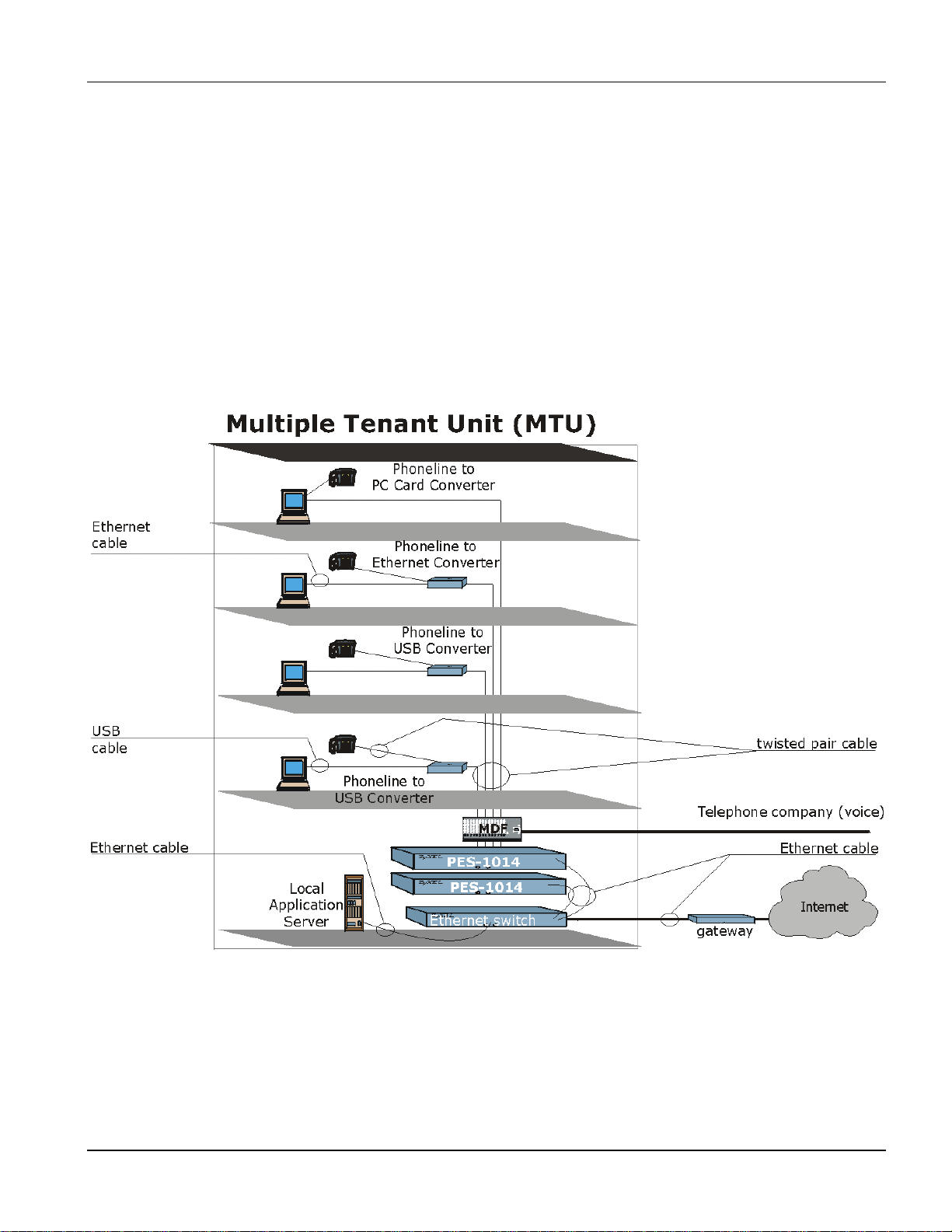
1.4 MTU Application
The PES-1014 delivers 1Mbps data service over existing copper telephone wires. It does not interfere with Plain
Old Telephone Service (POTS), digital telephone or ISDN traffic and does not require splitters. The PES-1014 is
also compatible with ADSL lines, allowing service providers to deploy the PES-1014 in buildings where broadband
service already exists. See the following figure for an example of an MTU installation.
Figure 1-1 MTU Application
Getting to Know the PES-1014 1-3
Page 16

Page 17
2.1 Front Panel
Refer to Appendix B
Safety Warnings and Instructions before installing the PES-1014.
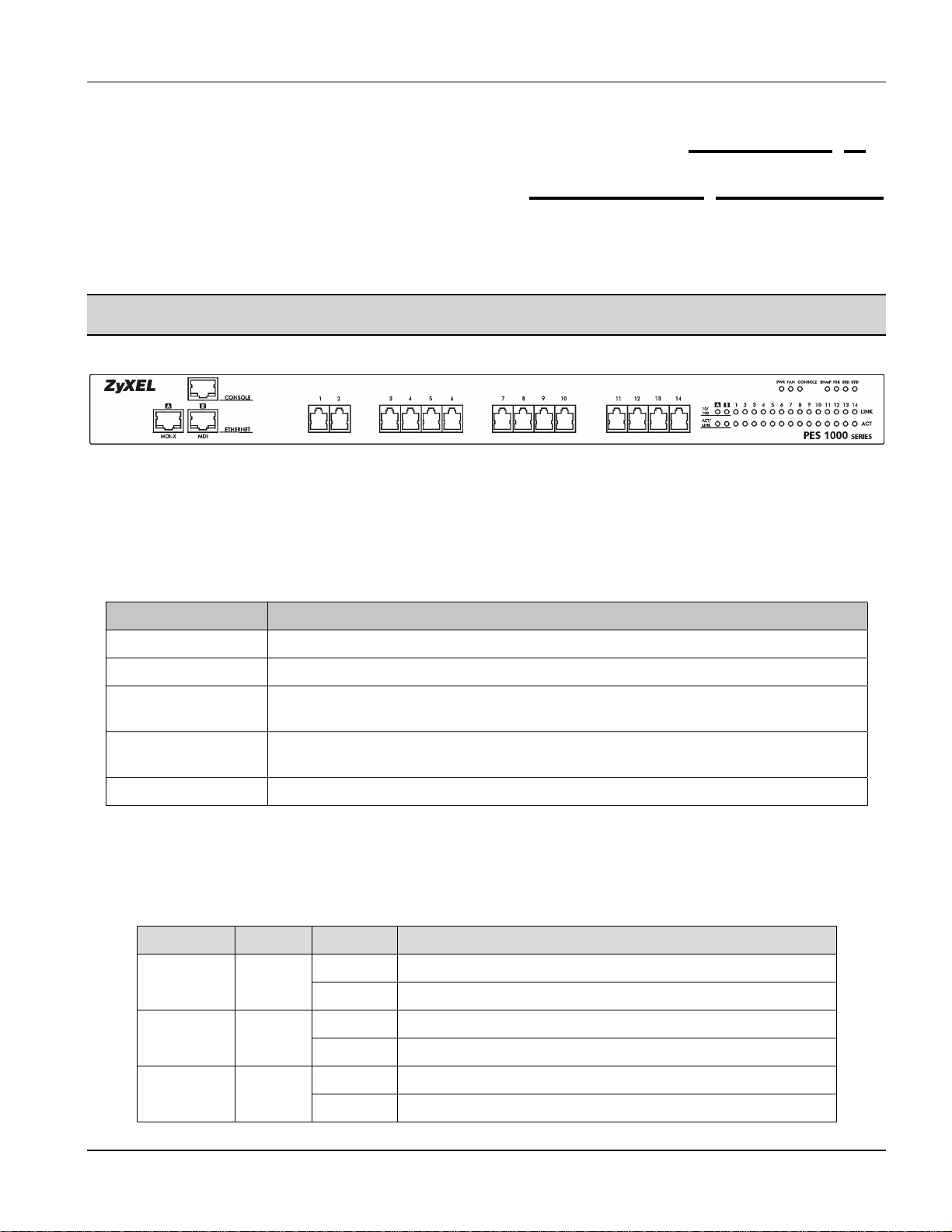
The following figure shows the front panel of the PES-1014.
Figure 2-1 PES-1014 Front Panel
2.1.1 Front Panel Ports
PES-1014 User’s Guide
Chapter 2
Hardware Overview
The following table describes the ports on the front panel of the PES-1014.
Table 2-1 Front Panel Ports
PORTS DESCRIPTION
CONSOLE An RJ-45 10/100 Mbps auto-sensing Ethernet port for configuring the PES-1014.
ETHERNET
A MDI-X An RJ-45 10/100 Mbps auto-sensing Ethernet port for WAN connection to a switch
or router.
B MDI An RJ-45 10/100 Mbps auto-sensing Ethernet port for WAN connection to a switch
or router.
1-14 RJ-11 ports that connect users to the PES-1014.
2.1.2 Front Panel LEDs
The following table describes the LED indicators on the front panel the PES-1014.
Table 2-2 PES-1014 Network Module LED Descriptions
LED COLOR STATUS DESCRIPTION
On The PES-1014 is receiving power.PWR Green
Off The PES-1014 is not receiving power.
On The fan is malfunctioning.FAN Orange
Off The fan is operating normally
On The CONSOLE port is connected.CONSOLE Green
Off The CONSOLE port is not connected.
Hardware Overview 2-1
Page 18

PES-1014 User’s Guide
LED COLOR STATUS DESCRIPTION
SNMP Green
PSR Green
SRD Green
STD Green
A, B (these are the Ethernet ports)
10/100 Green
ACT/LINK Green
1-14 (these are the phoneline ports)
These LEDs are used in a diagnostic test when the PES-1014 turns on.
They turn on and off one-by-one in the following order: SNMP> PSR>
SRD> STD. After this the SNMP will turn on again and remain on.
On The port is connected to a 100Mbps Ethernet.
Off The port is connected to a 10Mbps Ethernet.
Blinking The port link is sending/receiving data.
Off The port link is down.
On The phoneline-networking link is up.LINK Green
Off The phoneline-networking link is down.
Blinking The phoneline-networking link is sending/receiving data.ACT Green
Off The phoneline-networking link is not sending/receiving data.
2.2 Console Port
Connect the manager computer to the PES-1014’s console port using a straight-through Ethernet cable.
2.3 Ethernet Port Connections
These instructions detail how to connect to a switch.
Use a straight-through Ethernet cable to connect ETHERNET port A MDI-X to a switch.
Use a cross-over Ethernet cable to connect ETHERNET port B MDI to a switch.
Table 2-3 Connecting to a Switch
EHTERNET PORT ETHERNET CABLE TYPE
ETHERNET A MDI-X Straight-through
ETHERNET B MDI Cross-over
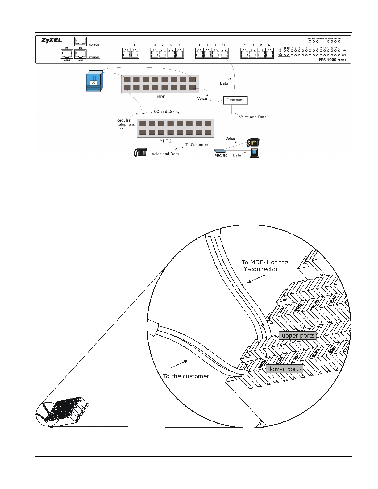
2.4 Phoneline Networking Port Connections
An MDF (Main Distribution Frame) is the point of termination for the telephone company and in-building
telephone lines. Use standard telephone wire to connect the RJ-11 ports (numbered 1-14) on the PES-1014 to Yconnectors and then the MDF.
The following diagram shows the connections between the RJ-11 phoneline networking ports and the customer’s
equipment. “CO” stands for the telephone company. Install an MDF with surge protection circuitry (MDF-1 in the
diagram) between the CO line and the PES-1014.
2-2 Hardware Overview
Page 19
PES-1014 User’s Guide
Figure 2-2 Phoneline Port Connections
2.4.1 MDF Connections
For MDF-1, install wires from the CO in the upper ports and to the Y-connector or MDF-2 in the lower ports. For
MDF-2, connect the upper ports to MDF-2 or the Y-connector and connect the customer lines to the lower ports.
Use a punch-down tool to seat the telephone wires in the MDF. An example of MDF connections is shown next.
Figure 2-3 MDF-2 Connections
Hardware Overview 2-3
Page 20

PES-1014 User’s Guide
2.5 Rear Panel
Make sure you are using a 100 — 240 Volt AC, 50 — 60 Hertz power source.
The following figure shows the rear panel of the PES-1014.
Figure 2-4 PES-1014 Rear Panel
Connect the female end of the power cord to the power receptacle on the rear panel of your PES-1014. Connect the
other end of the cord to a power outlet. Make sure that no objects obstruct the airflow of the fan (located on the side
of the unit).
2-4 Hardware Overview
Page 21
PES-1014 User’s Guide
Chapter 3
Getting Started
3.1 Port Naming
The Port labeled CONSOLE is referred to as the “out-of-band” port. All other ports (A, B, and 1-14) are referred to
as “in-band” ports.
3.2 Web Browser
Use IE 5.0 or later or Netscape 4.0 or later to access the web-based manager Make sure your computer’s IP address
is in the same subnet as the IP address of the port you are accessing (either out-of-band or in-band).
The default IP addresses are as follows:
192.168.11.1 for the CONSOLE port (out-of-band)
192.168.10.1 for all other ports (in-band)
After the first login, refer to 4.5 for information on configuring the switch’s IP address.
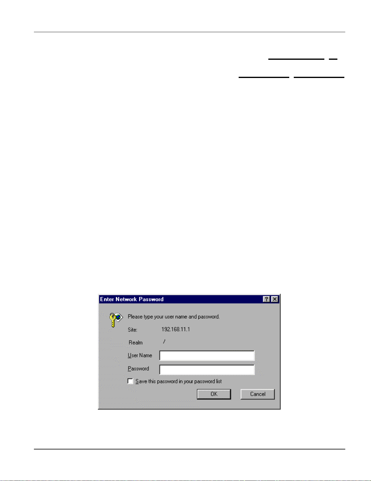
3.3 Login
Procedure for a first login (using the out- of-band console port):
Step 1.
Step 2.
Type in your PES-1014’s IP address as the URL in your web browser (192.168.11.1 for the out-of-band
console port).
The Enter Network Password screen appears as shown next.
Figure 3-1 Login
Step 3. The User Name and Password boxes have been set to “null” for the first login; just click OK.
Getting Started 3-1
Page 22

PES-1014 User’s Guide
Step 4. The web-based management system Welcome screen appears.
Refer to section 12.3 for adding accounts after logging in.
After adding accounts, type in the User Name and Password when logging in.
3.4 Welcome Screen
Figure 3-2 Welcome Screen
The Welcome screen gives you links to the main ZyXEL web-site and e-mail for support and sales.
Click Enter to go to the Main screen of the device manager.
3-2 Getting Started
Page 23
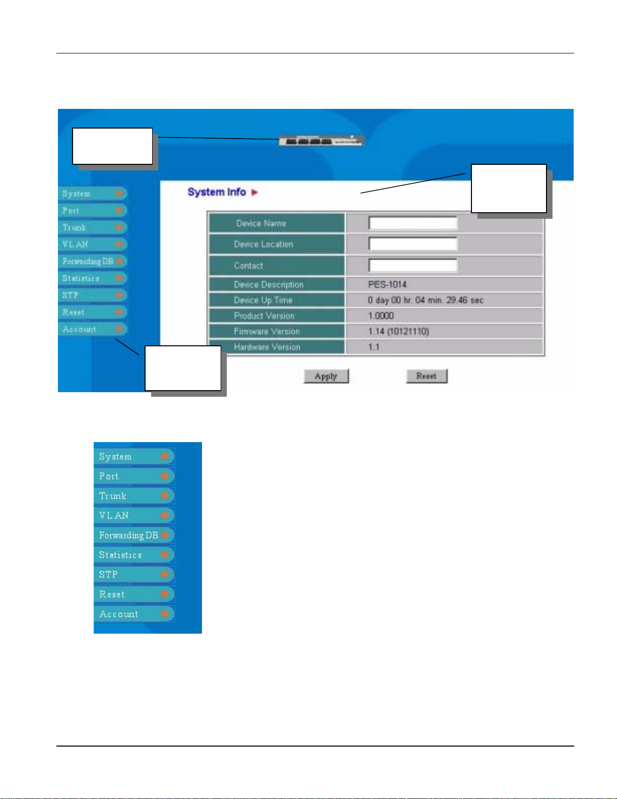
3.5 Main Screen
Switch Icon
PES-1014 User’s Guide
System
Information
Information Panel
Figure 3-3 Main Screen
3.5.1 Information Panel
The left side of the Main screen links you to every main subject of this
management system. Move the cursor over a link to bring up corresponding
submenus for further information.
Figure 3-7 Information Panel
Getting Started 3-3
Page 24
PES-1014 User’s Guide
Table 3-1 Information Descriptions
LINK DESCRIPTION
System Use System to view general system information and set related system functions.
Port Use Port to view information about the main functions and status of each port and set
individual port functions.
Trunk Use Trunk to view trunk status, and set trunk configuration and mapping.
VLAN Use VLAN to display VLAN status and edit VLAN setup.
Forwarding DB Use Forwarding DB to display the status of the MAC-based forwarding database and
edit entries.
Statistics Use Statistics to view the statistical contents of each port and host.
STP Use STP to edit the Spanning Tree Protocol switch and port parameters.
Reset Use Reset to reset counters and factory defaults or restart the switch.
Account Use Account to view and add/delete accounts or change passwords.
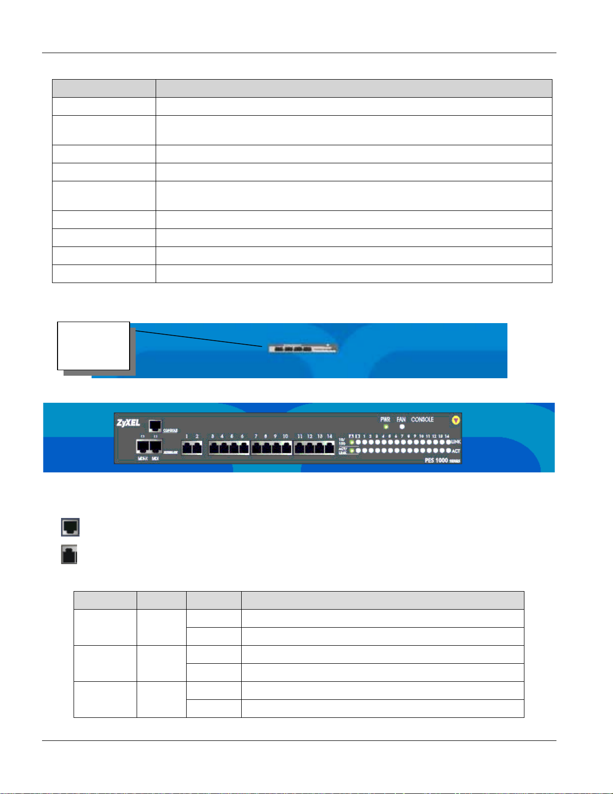
3.5.2 Front Panel
Click to
enlarge.
Figure 3-8 Switch Icon
Figure 3-9 Front Panel
On the front of the switch, we see different ports and LEDs.
•
•
Represents an Ethernet port.
Represents an RJ-11 Port
Table 3-2 Manager Front Panel LEDs
LED COLOR STATUS DESCRIPTION
On The PES-1014 is receiving power.PWR Green
Off The PES-1014 is not receiving power.
On The fan is malfunctioning.FAN Orange
Off The fan is operating normally
On The CONSOLE port is connected.CONSOLE Green
Off The CONSOLE port is not connected.
3-4 Getting Started
Page 25
LED COLOR STATUS DESCRIPTION
A, B (these are the Ethernet ports)
On The port is connected to a 100Mbps Ethernet.
10/100 Green
ACT/LINK Green
1-14 (these are the phoneline ports)
Dim The port is connected to a 10Mbps Ethernet.
Off The port link is down.
Blinking The port link is sending/receiving data.
On The phoneline networking link is up.LINK Green
Off The phoneline networking link is down.
Blinking The phoneline networking link is sending/receiving data.ACT Green
Off The phoneline networking link is not sending/receiving data.
• Click on a port to enter that port’s configuration screen.
You may modify the panel refresh time in the System Configuration screen.
Click the top-right icon of the panel to hide the front panel.
PES-1014 User’s Guide
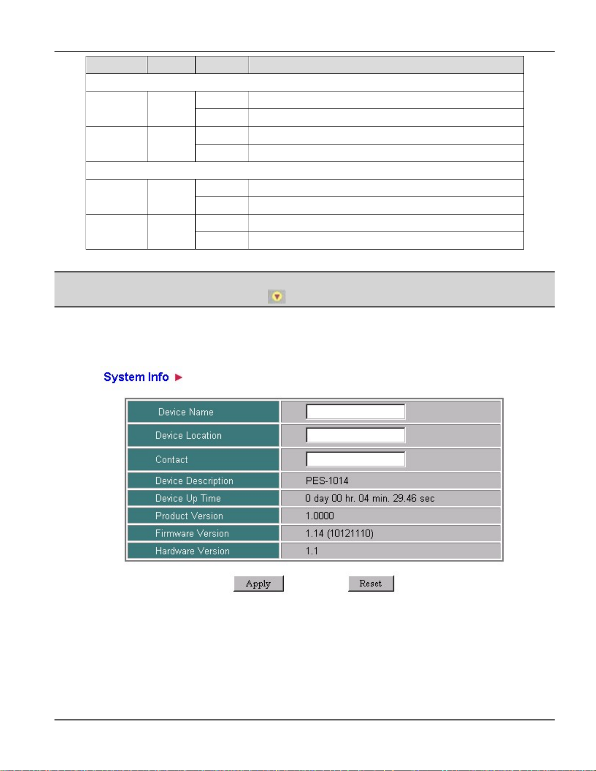
3.5.3 System Info
Figure 3-10 System Info
• This screen refreshes every 3 minutes.
• See 4.2 for detailed field descriptions.
Getting Started 3-5
Page 26

PES-1014 User’s Guide
3.5.4 Saving Changes
If you do not save your configuration changes to flash memory, all of your changes will be lost when the switch is
restarted. Use the following steps to save changes when you are done configuring a screen.
Step 1. Click Apply (this saves the settings to working memory).
Step 2.
Step 3. Click Save in the Save Changes screen (saves the settings to flash memory).
• Settings in the Networking screen will not take effect until the switch is restarted. Do the following to restart:
Step 4.
Step 5. Click Reboot and Saving.
Move your cursor over System in the Information Panel and click Save Changes.
Move your cursor over Reset in the Information Panel and click Reboot Device.
3.5.5 Reset
Click Reset to go to the screen’s previous configuration.
3-6 Getting Started
Page 27

4.1 Introduction
Move the cursor over the System link to display the submenus shown in the next figure.
PES-1014 User’s Guide
Chapter 4
System
Figure 4-1 System
System 4-1
Page 28

PES-1014 User’s Guide
4.2 System Info
Move the cursor over the System link and click System Info to display the System Info screen shown next.
Use this screen to display general system information and record the switch’s name, location and contact person.
Figure 4-2 System Info
Table 4-1 System Info Description
FIELD DESCRIPTION EXAMPLE
Device Name Type in up to 255 characters for the name of the switch
here. This field is case sensitive.
Device Location Type in up to 255 characters for the location of the switch
here. This field is case sensitive.
Contact Type in up to 255 characters for the name of the contact
person for this switch. This field is case sensitive.
Device Description This read-only field displays your device’s model name. PES-1014
Device Up Time This read-only field displays the length of time that your
device has been up and running since it was last initiated.
Click your browser’s refresh button to get up-to-date
information in this field.
Product Version This read-only field displays the version of your device. 1.0000
Firmware Version This read-only field displays the current firmware version of
your device.
Hardware Version This read-only field displays the current hardware version of
your device.
0 day 22 hr. 29 min. 39.91
Switch 1
Vienna Austria
Bob Administrator
sec
1.13 (9062153)
1.1
Click Apply to save your changes to working memory or click Reset to go to the previous configuration. Refer to
3.5.4 for directions on saving your changes to flash memory before you restart the switch.
4-2 System
Page 29

PES-1014 User’s Guide
4.3 System Configuration
Move the cursor over the System link and click System Configure to display the System Configuration screen
shown next.
Use the System Configuration screen to set up functions of the system. It can also set the counter and panel refreshing time intervals. These settings apply to the whole device.
Figure 4-3 System Configuration
Table 4-2 System Configuration Description
FIELD DESCRIPTION EXAMPLE
SuperMac
Aging Control
Aging Time
(0.30) min
Enable or Disable the capability of using a more aggressive backing off of
incoming pockets when collisions happen.
When set to Enable, the device will use a more aggressive back off algorithm
(back off max. 3 time slots) when collisions occur, instead of using the
standard Ethernet back off algorithm.
When set to Disable, the device will use the IEEE802.3 standard exponential
back off algorithm when collisions occur.
Enable or Disable the aging time of the forwarding database’s dynamic
entries. The address table is set by automatic address learning (dynamic) or
by manual entry (static). Aging Control is only available to dynamic entries.
Select Enable to make the switch age the dynamic address learning entries.
When you select Disable, the switch will not age the dynamic address
learning entries.
Configure this field to determine how long a source MAC address can stay in
the address look up table (forwarding database).
Select an Aging Time range from 0 to 30 minutes.
Disable
(default)
Enable
(default)
10
(default)
Broadcast Storm
Control
Threshold
Use this option to limit the number of consecutive broadcast packets
transmitted to the switch. The available selections are 16, 32, 48 or 64
packets. The PES-1014 discards consecutive incoming broadcast packets
that exceed this number.
48
(default)
System 4-3
Page 30

PES-1014 User’s Guide
FIELD DESCRIPTION EXAMPLE
Panel Refresh
Time Interval
(1..60) sec
Counter Refresh
Time Interval
(1..60) sec
Click Apply to save your changes to working memory or click Reset to go to the previous configuration. Refer
to 3.5.4 for directions on saving your changes to flash memory before you restart the switch.
Select how often you wish to refresh this screen. Options range from 1 to 60
seconds. You must reopen the page after configuring to make the new
settings active.
Select how often you wish to refresh the statistics counters. Options range
from 1 to 60 seconds. You must reopen the page after configuring to make
the new settings active.
10
(default)
10
(default)
4.4 Port Monitoring Configuration
The PES-1014 allows you to use a network analyzer (or sniffer) program on a computer to do port snooping on an
individual port. You can monitor and analyze data traffic, as well as capture packets. Move the cursor over the
System link and click Port Monitoring to display the Port Monitoring Configuration screen shown next.
Use this screen to specify a port to monitor and the snooping port(s) to do the monitoring. Only one monitored port
is allowed at one time. Different snooping ports can monitor the incoming and outgoing packet flows. Check the
Status boxes to enable the monitoring of the incoming or outgoing packet flows (or both).
Connect your monitoring computer (the one using the network analyzer) to Ethernet port A or B (whichever
one is not connected to a switch or router).
Figure 4-4 Port Monitoring Configuration
The ports in this screen are numbered 1-16. Ports 1 and 2 are the PES-1014’s physical ports A and B
(Ethernet). Ports 3-16 match the physical ports 1-14 (phoneline networking).
Table 4-3 Port Monitoring Configuration Description
FIELD DESCRIPTION EXAMPLE
Current Monitoring Port Status
Monitored Port ID Indicates the number of the monitored port. 1
Snooping Port ID for
Incoming packet flow
Indicates the snooping port that monitors the packet flow
coming into the monitored port. “-“ means disabled.
-
(default)
4-4 System
Page 31

PES-1014 User’s Guide
FIELD DESCRIPTION EXAMPLE
Snooping Port ID for
Outgoing packet flow
Monitored Port ID. Select the number of a port to monitor.
Status
Port Select the number of the port that will monitor the incoming
Click Apply to save your changes to working memory. Refer to 3.5.4 for directions on saving your changes to
flash memory before you restart the switch.
Performance of a monitored port degrades if incoming and outgoing packet snooping are both being
Indicates the snooping port that monitors the packet flow
coming out of the monitored port. “-“ means disabled.
Select the Status box to enable monitoring of the incoming
or outgoing packet flows.
or outgoing packet flows.
performed on it simultaneously.
-
(default)
1
Unchecked
(default)
2
4.5 Networking
Move the cursor over the System link and click Networking to display the Networking screen shown next. Select one of the two interfaces currently supported (In-Band and Out-of Band) in this management system.
Do not configure the Out-of-Band (CONSOLE port) and the In-Band (other por ts) to have the same IP
address.
Figure 4-5 Networking
Table 4-4 Networking Description
FIELD DESCRIPTION EXAMPLE
Current Status - These read-only fields display the current status of each interface.
Configuration
Interface This read-only field is the number of the type of interface that connects
to the switch.
Type This read-only field is the type of interface that connects to the switch.
Out-of-band stands for the console port and in-band stands for the
switch’s other ports.
1
Out-of-Band
System 4-5
Page 32

PES-1014 User’s Guide
FIELD DESCRIPTION EXAMPLE
Mac Address This read-only field is the Mac address calculated by the switch for
either the in-band ports or the out-of-band (console) port.
IP Address Type your IP address in this field.
Each time the IP address is changed, you must restart the switch
before the new IP address becomes effective.
Subnet Mask Type your subnet mask here (if you are using one).
Default Gateway The default gateway IP address is used when the switch tries to reach
a non-local IP host.
Use this field to assign a default gateway.
Set Default Route The default route is where the switch sends packets that it receives that
are not in its domain. Normally you select Inband to send these
packets through the in-band ports. Sel ec t Out-of Band if you have the
out-of-band port linked to a different subnet and want to send these
packets through the out-of-band port.
Click Apply to save your changes to working memory or click Reset to go to the previous configuration. Refer to
3.5.4 for directions on saving your changes to flash memory and restarting the switch. You must restart the
switch to make changes in this screen effective.
00-50-00-10-00-
50
192.168.10.1
(In-Band default)
255.255.255.0
192.168.10.254
(In-Band default)
Inband
4.6 SNMP
Manage and monitor the switch through the Simple Network Management Protocol (SNMP) Management
Information Base (MIB). Configure the fo llowing settings:
• Set the names of the community strings
• Set each community’s access right to either read-write or read-only.
• Set which community will receive SNMP traps
• Enable or disable certain communities
4.6.1 SNMP Community
Move the cursor over the System link and click SNMP to display the SNMP Community screen shown next.
Figure 4-6 SNMP Community
4-6 System
Page 33

PES-1014 User’s Guide
Table 4-5 SNMP Community Description
FIELD DESCRIPTION EXAMPLE
Community Give a name to each community (a group of nodes in a management host) in
this field. Each community must have a name (like a password) in order to
identify legitimate sources of SNMP requests, determine what information a
community can access and which functions that community is allowed to
perform.
Up to four communities can be assigned and ena bled in one system. The
community name is case sensitive and can be up to a maximum of 12
characters.
Access
Right
Trap
Receiving
Status
Click Apply to save your changes to working memory or click Reset to go to the previous configuration. Refer
to 3.5.4 for directions on saving your changes to flash memory before you restart the switch.
Select Read-Only, to allow the management host to perform read functions only.
Select Read-Write, to allow the management host to perform both read and
write functions.
Select Enable to allow the management host to receive SNMP Traps.
Select Disable to disallow the management host from receiving SNMP Traps.
Select Enable or Disable to enable or disable a specific community. Enable
You must get a valid Community string before enabling the specified Community.
public
(default)
Read-Write
(default)
Enable
(default)
(default)
4.6.2 SNMP Host
This SNMP Host screen gives SNMP host information. The maximum number of SNMP hosts is six. You must configure the SNMP Host screen for an SNMP server (like HP’s Open View) to be able to manage the PES-1014.
Figure 4-7 SNMP Host
Table 4-6 SNMP Host Description
FIELD DESCRIPTION EXAMPLE
IP Address Input the IP addresses of the management hosts so they
can receive SNMP trap messages.
Host Name This column indicates the name of the management host.
192.168.10.2
(default)
Factory SnmpM
System 4-7
Page 34

PES-1014 User’s Guide
FIELD DESCRIPTION EXAMPLE
The name is case sensitive and can be a maximum length
of 12 characters.
(default)
Community Indicates the name of the community that the management
host belongs to. See the previous figure or the top half of
the screen.
Status
Click Apply to save your changes to working memory or click Reset to go to the previous configuration. Refer to
3.5.4 for directions on saving your changes to flash memory before you restart the switch.
Select either Enable or Disable to enable or disable the
SNMP management functions of each management host.
public
(default)
Enable
(default)
4.7 Save Changes
Move the cursor over the System link and click Save Changes to display the Save Changes screen shown next. All
the settings mentioned above are stored only in working memory and are lost after the power is turned off. After
you configure settings, use the following procedure to store them:
Step 1.
Step 6.
Step 2.
Restart the device (see 3.5.4) to store the settings in long term memory.
Click Apply.
Click System in Information, and then Save Changes.
Click Save to save the settings into flash memory.
Figure 4-8 Save Changes
4.8 Firmware Upgrade
Use Internet Explorer 5.0 or later to upgrade the firmware.
Do not interrupt the upgrade process (interrupting it causes an error).
Restart the switch immediately after the upgrade is completed.
Move the cursor over the System link and click Software Upgrade to display the Firmware Upgrade screen shown next.
• Download the new version firmware file through Internet by web browser or FTP.
4-8 System
Page 35

Click
Upgrade
Figure 4-9 Firmware Upgrade
• A bar with the text “Upgrade in Progress” is displayed during the upgrade.
• The system will complete the upgrade process automatically.
• Restart the device to finish the upgrade process.
PES-1014 User’s Guide
Click Browse
and choose the
file stored on
your computer
System 4-9
Page 36

Page 37

5.1 Introduction
Move the cursor over the Port link to display the submenus shown in the next figure.
PES-1014 User’s Guide
Chapter 5
Port
Figure 5-1 Port bar
Port 5-1
Page 38

PES-1014 User’s Guide
5.2 All Ports Status
Move the cursor over the Port link and then click All Ports to display the All Ports Status screen shown next. This
screen shows the link status, transmission speed and duplex mode of the current ports. Click a port’s number to link
directly to the selected port.
Figure 5-2 All Ports Status
Table 5-1 All Ports Status Description
FIELD DESCRIPTION EXAMPLE
Port NO.
Port Name Give each port a name (up to 255 characters) for identification purposes.
Link This column indicates the current link status of each port. UP represents
Speed/Duplex This column shows each port’s current transmission speed of 10 Mbps or
STP Port Status This column represents the port’s status in STP (Spanning Tree
Click Port NO. to go to a port’s configuring screen.
This field is case sensitive.
connected DOWN represents disconnected.
100 Mbps, as well as its duplex. Refer to Table 5-2 for more information.
Duplex- “Full” indicates simultaneously sending and receiving
transmissions at 10Mbps or 100Mbps. “Half” indicates sending or
receiving at 10Mbps or 100Mbps in one dir ection only at a time.
Protocol). Possible states are forwarding, listening, learning, blocking and
“–“ (which means the Spanning Tree Protocol is disabled). Refer to
Chapter 10 for more information on STP.
A
myport
Up
100/FULL
-
5-2 Port
Page 39

PES-1014 User’s Guide
Table 5-2 Speed/Duplex Settings
SPEED/DUPLEX DESCRIPTION
100/FULL This port is simultaneously sending and receiving transmissions at
100 Mbps (full duplex).
10/FULL This port is simultaneously sending and receiving transmissions at
10Mbps (full duplex).
100/HALF This port is sending or receiving at 100Mbps in one direction only
at a time (half duplex).
10/HALF This port is sending or receiving at 10Mbps in one direction only at
a time (half duplex).
5.3 Port Configuration
Click on a port’s Port NO. in the All Ports Status screen to bring up the Port Configuration screen. Use this screen to configure the specified port.
Figure 5-3 Port Configuration
Table 5-3 Port Configuration Description
FIELD DESCRIPTION EXAMPLE
Port ID The letter or number that identifies this port.
Port Name Give each port a name (up to 255 characters) for identification purposes.
This field is case sensitive.
Access Status
Connector This read-only field shows the port’s connector type. There are RJ-11
Select Enable or Disable to enable or disable port access. Enable
phone connectors for the phoneline networking ports and TX (RJ-45)
Ethernet connectors for the Ethernet ports.
A
myportname
(default)
TX
Port 5-3
Page 40

PES-1014 User’s Guide
FIELD DESCRIPTION EXAMPLE
Security
Address Learning
Full Duplex Flow
Control (802.3x)
(Ethernet ports
only)
Auto Negotiation
(Ethernet ports
only)
Speed/Duplex
(Ethernet ports
only)
Broadcast Storm
Control
Use the Security box to set up security functions for the selected port.
Select Enable, to have the switch discard all packets that violate the
security parameters. A security violation is defined as any incoming
packet that does not match an SA (Source MAC Address) in the
forwarding database. W hen Disable is selected, the SA of incoming
packets is not checked. See 8.2.2 for information on adding static entries
to the forwarding database.
Select Enable to enable or Disable to disable dynamic MAC address
learning.
Select Enable to enable or Disable to disable 802.3x Full Duplex Flow
control.
When you select Enable the port automatically negotiates the
transmission rate and duplex mode.
When you select Disable auto negotiation is turned off and you need to
specify the transmission rate and duplex mode manually.
Select the data transmission rate and duplex mode of the selected port
(see Table 5-2).
To enable the forcing mode operation, you must disable auto-negotiation.
Select Enable to turn on Broadcast Storm Control. This discards
consecutive incoming broadcast packets that exceed the programmed
threshold (set in the system configuration screen).
Disable
(default)
Enable
(default)
Enable
(default)
Enable
(default)
100 Full
(default)
Enable
(default)
Select Disable to cancel Broadcast Storm Control.
Click Apply to save your changes to working memory or click Reset to go to the previous configuration. Refer
to 3.5.4 for directions on saving your changes to flash memory before you restart the switch.
5.4 Port Assigned
Move the cursor over the Port link and then click Port Assigned to display the Port Assigned screen shown next. Use the Port Assigned screen to copy a selected port’s settings to other ports.
5-4 Port
Page 41

PES-1014 User’s Guide
Figure 5-4 Port Assigned
Table 5-4 Port Assigned Description
FIELD DESCRIPTION
Source Port Select the port with the settings that you want to duplicate to other ports.
Target Port Select the port(s) to which you want to copy the settings of the source port.
Click Select All Ports to select all ports and Clear All Ports to clear all ports.
Item Choose up to four properties to copy from the Source Port to the target port(s).
Click Apply to save your changes to working memory. Refer to 3.5.4 for directions on saving your
changes to flash memory before you restart the switch.
Port 5-5
Page 42

Page 43

PES-1014 User’s Guide
Chapter 6
Trunk
6.1 Introduction
“Trunking” means aggregating multiple low-speed physical links onto a single higher-speed logical link. For
example, two Fast Ethernet (100Mbps) links could be aggregated into one single 200Mbps link.
Trunking is an advanced feature of the PES-1014. Exercise extreme caution if you decide to configure
these menus.
Configure up to four trunks with two to four ports in each trunk. The last number of the trunk set must be port 2, 6,
10, or 14. Within each trunk set, you may freely gather two to four ports into one trunk. For example, you cannot
group ports 2 and 3 to form a trunk, because they are not in the same trunk set; but you can use ports 3, 4 and 6 to
form a trunk. Ethernet port A is trunk port A and RJ 11 port 1 is trunk port 1.
6.2 Load-balancing Methods
There are two load-balancing methods for aggregating ports onto a trunk.
6.2.1 MAC-based Load-balancing
You can only use this method of you are aggregating the maximum of four ports into one trunk. It determines
which port to forward an incoming packet to by examining two bits (that you designate) of its source MAC address
and destination MAC address.
6.2.2 Port-based Load-balancing
Using this method, you have to determine which trunk port to link with a non-trunk port so that the load is balanced
among all trunk ports.
6.3 Trunk Menus
Move the cursor over the Trunk link to display the submenus shown in the next figure.
Trunk 6-1
Page 44

PES-1014 User’s Guide
Figure 6-1 Trunk
6.3.1 Current Trunk Status
Move the cursor over the Trunk link and click Current Status to display the Trunk Status screen shown next.
This read-only screen displays the current status of each trunk, including which Load-balance method you are using
and which ports are assigned to which trunk. Ports A and B are the Ethernet ports. Ports 1 to 14 are the Phoneline
ports.
Figure 6-2 Trunk Status Screen
6.3.2 Load Balancing Method Selection
Move the cursor over the Trunk link and click Mode Selection to display the Load Balancing Method Selection
screen shown next. The default is MAC Address Based Meth od. For each selection there is a corresponding
submenu to configure.
6-2 Trunk
Page 45

PES-1014 User’s Guide
Figure 6-3 Load Balancing Mode Selection Screen
6.3.3 MAC-based Mode Trunk Configuration
Configure this screen when you choose MAC Address Based Method in the previous screen. Select which trunk
should use MAC Address Based Method load balancing and which ports should be included in the selected
trunk(s). Each trunk selected must contain four ports. Once a trunk is selected, the corresponding four ports will
trunk automatically according to the your MAC Based Mode Bit Selection.
Figure 6-4 MAC-based Mode Trunk Configuration Screen
MAC Address Based Mode Bit Selection
Port trunking is determined by a packet’s source MAC address (SA) and destination MAC address (DA). Select
which bit-pair ([0:1], [2:3], [4:5], [6:7]) you want the management system to select from the SA and DA of each
incoming Ethernet data packet. The management system then maps the packet to a port according to the procedure
discussed next.
Trunk 6-3
Page 46

PES-1014 User’s Guide
The designated two bits of the SA and DA are Exclusive Or’d (XOR).
Table 6-1 Exclusive Or
BINARY BIT PAIR XOR RESULT
[0, 0] 0
[0, 1] 1
[1, 0] 1
[1, 1] 0
These combinations map to trunk ports as shown next. The left value represents SA and the right represents DA.
Table 6-2 Bit Selection Port Assignment
XOR RESULT
PAIR
[1, 1] trunk port 1
[1, 0] trunk port 2
[0, 1] trunk port 3
[0, 0] trunk port 4
PORT FORWARDED TO
MAC Address Based Mode Bit Selection Example
Select Trunk 2 from Trunk Assignment and [0,1] MAC Address Based Mode Bit Selection in the MAC-based
Mode Trunk Configuration screen.
The following two packets are forwarded as follows:
Table 6-3 MAC Address Based Mode Bit Selection Example
PACKET SA DA PORT FORWARDED TO
Packet 1 00:C0:A7:98:FE:81
Packet 2 00:C0:A7:98:FE:80
1
3
00:C0:A7:98:FE:9B2Port 4 (trunk port 2).
00:C0:A7:98:FE:9A4Port 5 (trunk port 3).
6.3.4 Port-based Mode Trunk Configuration
Assign ports that map to a trunk in this screen when you choose Port Based M e th od in the Load Balancing Mode
Selection screen shown previously. Aggregate between two and four ports to each trunk.
1
The last two bits are “81” which is “10000001” binary. Exclusive Or these last two (least significant) bits (01) to give “1”.
2
The last two bits are “9B” which is “10011011” binary. Exclusive Or these last two bits (11) to give “0”. [1,0] maps to trunk
port 2 according to the table above. As Trunk 2 is selected, trunk port 2 is Port 4.
3
The last two bits are “80” which is “10000000” binary. Exclusive Or these last two bits (00) to give “0”.
4
The last two bits are “9A” which is “10011010” binary. Exclusive Or these last two bits (10) to give “1”. [0,1] maps to trunk
port 3 according to the table above. As Trunk 2 is selected, trunk port 3 is Port 5.
6-4 Trunk
Page 47

PES-1014 User’s Guide
Figure 6-5 Port-based Mode Trunk Configuration Screen
6.3.5 Port-based Mode Port Mapping
Move the cursor over the Trunk link and click P. Mode Mapping to display the Port-based Mode Port Mapping
screen shown next. Use this screen to view and modify port mappings of assigned trunks when using Port-based
Load Balancing.
Figure 6-6 Port-based Mode Mapping Screen
After configuring, click Apply to make the changes effective or click Reset to go back to the previous
configuration. Select one trunk at a time for port mapping.
Table 6-4 Port-based Mode Mapping
FIELD DESCRIPTION
Trunk ID This field displays the number of the trunk that is currently displayed. Use the down
arrow to select the number of another trunk that has been set to Port Based Mode. If
no trunk has been set to Port Based Mode, the screen will show “none”.
Trunk Port These are the trunk ports in the trunk ID that you selected above.
Assigned This field shows whether or not individual trunk ports have been assigned to this
trunk.
Trunk 6-5
Page 48

PES-1014 User’s Guide
FIELD DESCRIPTION
Port to Trunk Port
Mapping
Click Apply to save your changes to working memory or click Reset to go to the previous configuration. Refer
to 3.5.4 for directions on saving your changes to flash memory before you restart the switch.
Click radio buttons to select ports to map to trunk ports.
6-6 Trunk
Page 49

PES-1014 User’s Guide
Chapter 7
VLAN
7.1 Introduction
VLAN (Virtual Local Area Network) is basically a broadcast domain. In an ordinary switched network system, a
broadcast packet or an unknown destination MAC address packet is broadcasted to all ports and that will decrease
network performance dramatically. By grouping some ports into one VLAN, broadcast packets will be sent only to
the ports within that VLAN without affecting the traffic of other ports. Any two or more ports can be grouped as
one VLAN in the device, and an overlapping VLAN port is permitted.
Move the cursor over the VLAN link to display the submenus shown in the next figure.
Figure 7-1 VLAN
7.1.1 VLAN Status
Move the cursor over the VLAN link and click Current Status to display the read-only VLAN Status screen shown next. This screen shows the current VLAN status in the switch. Click the Group ID (number of a VLAN Group) to set the related attributes of that group regarding Status, Name and Port Members.
• VLAN Group 1 is the default VLAN setting, with all ports included. You must disable VLAN Group 1 for new
VLAN groups to take effect.
• Enabling STP enables the default VLAN automatically. Disabling the default VLAN disables STP and vice
versa.
VLAN 7-1
Page 50

PES-1014 User’s Guide
Figure 7-2 VLAN Status
Table 7-1 VLAN Status Description
FIELD DESCRIPTION
Group ID There are 128 possible VLAN Groups (VLAN Group 1 is the default and non-editable).
Click any of the other Group ID numbers to display the corresponding VLAN editing screen.
VLAN Status This column indicates the current status of all VLAN groups. “Enable” means that the
selected VLAN is active. “Disable” means that the selected VLAN is inactive.
VLAN Name This is the name of a VLAN group. The maximum length for this name is 32 characters.
This field is case sensitive.
Port Members This column shows the participating ports of a particular VLAN group. Add or delete port
members by doing edits in the Edit VLAN screen.
7.2 Edit VLAN Group
Move the cursor over the VLAN link and click Edit VLAN to display the Edit VLAN Group screen shown next.
Use this screen to modify a VLAN group’s list of port members, activity status, and name.
Figure 7-3 Edit VLAN Group
7-2 VLAN
Page 51

PES-1014 User’s Guide
Table 7-2 Edit VLAN Group Description
FIELD DESCRIPTION EXAMPLE
Group ID
Status
Group Name This is the name of the selected VLAN Group. The name is case sensitive and
Port Members
Click Apply to save your changes to working memory or click Reset to go to the previous configuration. Refer
to 3.5.4 for directions on saving your changes to flash memory before you restart the switch.
Each VLAN group has a number as its ID (as the VLAN Status screen
showed). Select the ID number of a VLAN group for editing.
Select Enable to activate or Disable to de-activate a selected VLAN group.
Disabling a VLAN Group only deactivates it.
can be up to 32 characters.
To modify port members, select Port Members of a group by clicking the
checkbox on the table.
At least two ports must be selected to form a VLAN group.
6
Enable
Home
!
VLAN 7-3
Page 52

Page 53

PES-1014 User’s Guide
Chapter 8
Forwarding DB (Database)
8.1 Introduction
The switch will check the forwarding database before sending data packets to make sure all of the packets are sent
correctly. The forwarding database (address table, look up table, forwarding table) can be built by dynamic
(automatic) address learning or by static (manual) entry. When using dynamic address learning, it is possible to age
out certain entries if aging control is enabled and the aging time expires; but it is also keeps updating for new
packets received with different SAs.
The switch does not age out or update static entries. The only way to change the static entries is through manual
editing in the Edit Static Entry screen.
Moving the cursor over the Forwarding DB link brings up the following submenus.
Figure 8-1 Forwarding Database Bar
Enabling the Security setting for a port in the Port Configuration screen (5.3) automatically disables the aging
out timer for that port and changes it to a static entry in the forwarding database.
8.2 Current Forwarding DB Status
Move the cursor over the Forwarding DB link and click Current Status to display the Current Forwarding DB
Status screen shown next. This screen shows the current forwarding database status. A total of 1K MAC address
entries can be stored in the device.
Forwarding Database 8-1
Page 54

PES-1014 User’s Guide
Figure 8-2 Current Forwarding DB Status
Table 8-1 Current Forwarding DB Status Description
FIELD DESCRIPTION EXAMPLE
Refresh Data
Screen A total of 20 screens are available in the management system for the
ID
Port/Trunk/CPU
MAC
Static/Dynamic This column indicates the static or dynamic method of entry for each
Click Refresh Data to get the current forwarding database of the
management system. How many screens can be viewed depends on
how many entries are currently in the database.
maximum 1024 addresses.
Indicates the number of an entry. Click ID to sort the table in
descending or ascending order.
Port/Trunk/CPU shows whether the MAC address of a received packet
is from a port, trunk or the switch respectively. Click Port/Trunk/CPU to
sort the table in descending or ascending order.
This column indicates the MAC address of each entry. Click MAC to
sort the table in descending or ascending order.
address. Click Static/Dynamic to sort the table in descending or
ascending order.
1
1
Port B
00-45-12-34-56-78
Dynamic
8.2.1 Current Static Entries
A static entry is one that can only be changed manually and is not aged out by dynamic address learning.
Move the cursor over the Forwarding DB link and click Current Static E. to display the Current Static Entries
screen shown next. This screen shows the current status of the static address table, which includes port/trunk and
the MAC address.
Only activated static entries are shown on this screen.
8-2 Forwarding Database
Page 55

PES-1014 User’s Guide
Figure 8-3 Current Static Entries
Table 8-2 Current Static Entries Description
FIELD DESCRIPTION EXAMPLE
ID This management system supports 256 explicit static address entries, click
each entry’s ID to get the Edit Static Entry screen for editing.
Port/Trunk This column indicates the member port of each static address entry. Port 9
MAC This column shows the address of each static address entry. Each entry is a 12
digit, real MAC address.
Each entry must have a unique MAC address in the system.
1
00-C0-00-00-
00-1A
8.2.2 Edit Static Entry
Move the cursor over the Forwarding DB link and click Edit Static E. to display the Edit Static Entry screen
shown next. Choose a static entry to edit its status, as well as port or trunk.
Figure 8-4 Edit Static Entry
Forwarding Database 8-3
Page 56

PES-1014 User’s Guide
Table 8-3 Edit Static Entry Description
FIELD DESCRIPTION EXAMPLE
Entry ID There are 256 static entries available in the system, and each static entry must
have a unique ID number (from 1 to 256). Select an Entry ID to link to its
corresponding static entry for editing.
Status
Port/Trunk
Member
MAC Enter the MAC address of the computer’s Network Interface Card (NIC) that you
Click Apply to save your changes to working memory or click Reset to go to the previous configuration. Refer
to 3.5.4 for directions on saving your changes to flash memory before you restart the switch.
Select Enable to activate or Disable to deactivate the selected static entry.
Disabled static entries will not be sh o wn on the Current St atic En trie s screen.
Click one radio button in either the Port column or the Trunk column.
are connecting to. You must assign a unique and legal MAC address for each
static entry for security identification and port selection purposes while transmitting.
Different entries can be assigned with the same port/trunk, but the MAC addresses
have to be different.
1
Enable
00.00.00.0
0.00.1A
8-4 Forwarding Database
Page 57

PES-1014 User’s Guide
Chapter 9
Statistics
9.1 Introduction
Statistics leads to the statistical contents of each port and host, all figures reflect the latest facts since the last time
the port has been turned on.
Move the cursor over Statistics to bring up the following submenus.
All counters are updated every 10 seconds by default.
Figure 9-1 Statistics
Statistics 9-1
Page 58

PES-1014 User’s Guide
9.2 TX/RX Counters
Move the cursor over the Statistics link and click TX/RX Counters to display the TX/RX Counters screen shown next.
Figure 9-2 TX/RX Counters
Table 9-1 TX/RX Counters Description
FIELD DESCRIPTION
Port ID This is the label of a port.
Packet TX The port’s total number of successfully transmitted packets. This is the sum of unicast TX,
multicast TX, and broadcast TX packets.
Packet RX The port’s total number of good packets received. This is the sum of unicast RX, multicast RX,
and broadcast RX packets.
Byte TX The port’s total number of successfully transmitted data bytes.
Byte RX The port’s total number of data bytes received.
9-2 Statistics
Page 59

PES-1014 User’s Guide
9.3 Error Counters
Move the cursor over the Statistics link and click Error Counters to display the Error Counters screen shown next.
Figure 9-3 Error Counters
Table 9-2 Error Counters Description
FIELD DESCRIPTION
Port ID This is the label of a port.
Fragment Represents the number of packets received that were less than 64 octets long, and had either
an alignment or CRC (Cyclic Redundant Check) error.
Jabber Represents the number of packets received that were longer than the maximum octet length
(specified for the system by the configuration software) and had either a CRC or alignment
error.
Alignment The number of packets received that were of the proper size but had a CRC error and a non-
integral number of octets.
Late
Collision
The number of times a collision was detected later than the first 512 bits of a transmission.
Statistics 9-3
Page 60

PES-1014 User’s Guide
9.4 Packet Analysis (TX)
Move the cursor over the Statistics link and click Packet Analysis(TX) to display the Packet Analysis (TX)
screen shown next.
Figure 9-4 Packet Analysis (TX)
Table 9-3 Packet Analysis (TX) Description
FIELD DESCRIPTION
Port ID This is the label of a port.
64 in_length The number of packets (including bad packets) transmitted that were 64 octets in length.
65-127 The number of packets (including bad packets) transmitted that were between 65 and 127
octets in length.
128-255 The number of packets (including bad packets) transmitted that were between 128 and 255
octets in length.
256-511 The number of packets (including bad packets) transmitted that were between 256 and 511
octets in length.
512-1023 The number of packets (including bad packets) transmitted that were between 512 and 1023
octets in length.
1024-1518 The number of packets (including bad packets) transmitted that were between 1024 and
1518 octets in length.
9-4 Statistics
Page 61

PES-1014 User’s Guide
9.5 Packet Analysis (RX)
Move the cursor over the Statistics link and click Packet Analysis(RX) to display the Packet Analysis (RX)
screen shown next.
Figure 9-5 Packet Analysis (RX)
Table 9-4 Packet Analysis (RX) Description
FIELD DESCRIPTION
Port ID This is the label of a port.
64 in_length The number of packets (including bad packets) received that were 64 octets in length.
65-127 The number of packets (including bad packets) received that were between 65 and 127
octets in length.
128-255 The number of packets (including bad packets) received that were between 128 and 255
octets in length.
256-511 The number of packets (including bad packets) received that were between 256 and 511
octets in length.
512-1023 The number of packets (including bad packets) received that were between 512 and 1023
octets in length
1024-1518 The number of packets (including bad packets) received that were between 1024 and 1518
octets in length.
Statistics 9-5
Page 62

PES-1014 User’s Guide
9.6 Packet Attribute
Move the cursor over the Statistics link and click Packet Attributes to display the Packet Attribute screen shown next.
Figure 9-6 Packet Attribute
Table 9-5 Packet Attribute Description
FIELD DESCRIPTION
Port ID This is the label of a port.
Unicast TX The total number of good packets addressed to a unicast address that the port transmitted.
Unicast RX The total number of good packets addressed to a unicast address that the port received.
Multicast TX The total number of good packets addressed to a multicast address that the port
transmitted.
Multicast RX The total number of good packets addressed to a multicast address that the port received.
Broadcast TX The total number of good packets addressed to a broadcast address that the port
transmitted.
Broadcast RX The number of good broadcast packets received.
9-6 Statistics
Page 63

PES-1014 User’s Guide
9.7 Collision Info
Move the cursor over the Statistics link and click Collision Info to display the Collision Info screen shown next.
Figure 9-7 Collision Info
Table 9-6 Collision Info Description
FIELD DESCRIPTION
Port ID This is the label of a port.
0 Collision The number of packets with no collision detected.
1 Collision The number of packets with 1 collision detected.
Multi Collisions The number of packets with 2 to 15 collisions detected.
Excessive Collision The number of packets with more than 15 collisions detected.
Statistics 9-7
Page 64

PES-1014 User’s Guide
9.7.1 Single Port Statistics
Move the cursor over the Statistics link and click Single Port to display the Single Port Statistics screen shown
next. This screen displays the single port information of a selected Port ID. See earlier in this chapter for field
descriptions.
Figure 9-8 Single Port Statistics
Table 9-7 Single Port Statistics Description
FIELD DESCRIPTION
Port ID This is the label of a port. Select one to see its statistics.
Clear Counter
Click Clear Counter to reset a selected port’s counters to zero.
9-8 Statistics
Page 65

PES-1014 User’s Guide
Chapter 10
STP
10.1 Introduction
Spanning Tree Protocol (STP) is IEEE standard (802.1d) that avoids looping in the network while maintaining
multiple Ethernet bridges. STP can avoid loops by placing ports in forwarding state or in blocking state to establish
redundant paths. When STP is enabled, the switch will execute STP Bridge Protocol Data Unit (BPDU) packets as
below:
• If the port is in Block-N-Listen State or Learning State, the BPDU packet is forwarded to the CPU, other
packets are discarded.
• If the port is in the Forwarding State, the BPDU packet is forwarded to the CPU, all other packets are normally
forwarded based on the switch engine decision.
Move the cursor over STP to bring up the following submenus.
Figure 10-1 STP
10.2 Spanning Tree Configuration (Bridge) – (Switch Parameters)
Move the cursor over the STP link and click Switch Parame te rs to display the Spanning Tree Configuration
(Bridge) screen shown next.
STP 10-1
Page 66

PES-1014 User’s Guide
Figure 10-2 Spanning Tree Configuration (Bridge)
Table 10-1 Spanning Tree Configuration (Bridge) Description
FIELD DESCRIPTION EXAMPLE
Spanning
Tree
Protocol
state
Bridge
Priority
(0.65535)
Root Bridge
Priority
Root Bridge
MAC
Address
Root Port This read-only field shows the port that offers the lowest cost path from this bridge
Root Path
Cost
Bridge Hello
Time (1..10)
sec
Bridge Max
Age (6..40)
sec
Select Enable to activate or Disable to deactivate the Spanning Tree Protocol.
Enabling the STP also enables the default VLAN. Disabling the default VLAN also
disables the STP, and vice versa.
Bridge priority decides whether a bridge in a multi-bridge network is a root bridge
or not, a lower numbered bridge priority induces more chance of the switch
becoming the root bridge. Bridge Priority can be set from 0 to 65535.
This is the bridge priority of the root bridge on this network. 32768
This is the MAC address of the root bridge of the network. 00-50-00-
to the root bridge.
This read-only field contains the lowest cost for connecting this bridge to the root
bridge through the root port.
The time interval between BPDU packets in STP, all of the bridges will send the
BPDU packet to elect the root bridge periodically. The root bridge will keep
sending the packets to make sure it is still the root bridge after it has been
elected. Bridge Hello Time can be set from 1 to 10 seconds, the default value is
set at 2 seconds.
Bridges will begin to send BPDU packets for electing a new Root Bridge if they
receive no BPDU packets from the Root Bridge for longer than the time period in
Bridge Max Age. Bridge Max Age ranges from 6 to 40 seconds, the default
value is 20 seconds.
Disable
(default)
32768
(default)
10-10-28
0
0
2
20
Forward
Delay
(4..30) sec
Click Apply to save your changes to working memory or click Reset to go to the previous configuration. Refer
to 3.5.4 for directions on saving your changes to flash memory before you restart the switch.
Forward Delay determines how long the switch waits before changing its STP
status from listening/learning to learning/forwarding.
You can modify the Forward Delay time to fit your network topology. Larger
networks need longer delay times.
15
(default)
10-2 STP
Page 67

PES-1014 User’s Guide
10.3 Spanning Tree Configuration (Port)
Move the cursor over the STP link and click Port Parameters to display the Spanning Tree Configuration (Port)
screen shown next. This screen consists of the priority related settings: path cost and port state.
Figure 10-3 Spanning Tree Configuration (Port)
Table 10-2 Spanning Tree Configuration (Port) Description
FIELD DESCRIPTION EXAMPLE
Port ID Select a port to configure. Only the leading port of the trunk is shown to represent
its role in the spanning tree protocol if the trunk is set.
Priority
(0.255)
Path Cost
(1.65535)
Port State This read-only field displays the Spanning Tree Port condition:
Click Apply to save your changes to working memory or click Reset to go to the previous configuration. Refer
to 3.5.4 for directions on saving your changes to flash memory before you restart the switch.
Priority decides which port should be disabled when more than two ports form a
loop in a switch. A higher priority value means that the port is easier to disable.
Priority ranges from 0 to 255.
Displays the path cost of the port. When more than one port in the switch is
connected to the Root Bridge by more than one path (through different ports), only
the port with lowest path cost is active. Path cost ranges from 1 to 65535.
Blocking forwards an incoming packet to the CPU only if it is a BPDU packet; other
packets are discarded.
Listening acts as blocking state, it does not forward any packet, except BPDU
packets, and enters the learning state when possible.
Learning state learns the source addresses of incoming packets, except BPDU
packets, and immediately discarded.
Forwarding state forwards all source addresses of the incoming packet are learned
based on the switch engine’s decision.
2
128
(default)
19
(default)
Forwarding
STP 10-3
Page 68

Page 69

11.1 Introduction
Move the cursor over Reset to bring up the following submenus.
PES-1014 User’s Guide
Chapter 11
Reset
Figure 11-1 Reset
11.2 Reset Counters
Move the cursor over the Reset link and click Reset Counters to display the Reset Counters screen shown next. Use this screen to reset all the counters of your device.
Figure 11-2 Reset Counters
Click Apply to reset all counters of the device (the statistic counters) to zero.
Reset 11-1
Page 70

PES-1014 User’s Guide
11.3 Reset To Factory Default
Move the cursor over the Reset link and click Factory Default to display the Reset to Factory Default screen
shown next. Use this screen to reload the factory default settings and restart the switch to make the factory defaults
effective.
Figure 11-3 Reset to Factory Default
Click Reboot to reset the facto ry default s and erase customer settings.
Resetting to factory defaults erases all customer settings (except the Networking screen in the System
menu).
11.4 Reboot Device
Move the cursor over the Reset link and click Factory Default to display the Reset to Factory Default screen
shown next. Use this screen to restart the switch and save your configuration changes.
Figure 11-4 Reboot Device Screen
Click Reboot Without Saving to restart the device without saving changes
or
Click Reboot and Saving to save your setting changes (all changes will be effective after the device restarts).
11-2 Reset
Page 71

PES-1014 User’s Guide
Chapter 12
Account
12.1 Introduction
This system provides authentication procedures to ensure security. Up to seven pairs of user ID and password are
available. Both the user ID and password of the factory default are null string. ZyXEL recommends adding new
accounts for security protection immediately after you enter the system. Anyone trying to access the switch is
prompted to type in an ID and password after any account is properly established.
Move the cursor over Account to bring up the following submenus.
Figure 12-1 Account Bar
12.2 Browse Account List
Move the cursor over the Account link and click Browse Account to display the Account List screen shown next.
This read-only screen lists all the valid accounts of the device.
Figure 12-2 Account List
Account 12-1
Page 72

PES-1014 User’s Guide
Table 12-1 Account List Description
FIELD DESCRIPTION EXAMPLE
User ID This name identifies an individual account. Bruce
Password This is the password that an individual must enter to access the account. “*******” is
displayed.
Access
Level
This field divides accounts into two levels: power user and normal user. A power
user has full (read-write) access to the system. A normal user is limited to re adonly operations.
********
power user
12.3 Add/Del Account
Move the cursor over the Account link and click Add/Del Account to display the Add/Del Account screen shown next. Use the Add/Del Account screen to add or delete accounts. You must fill out all three boxes on this screen (User ID, Password, and Access Level) in order to add or delete accounts.
The first valid account must be a power user account. If you try to add a normal user account into the system for the
first configuration, you will get an “Account operation failure” message and have to try again.
At least one power user must exist in the account. To delete the last power user will also lead to a “Account
operation failure”.
Figure 12-3 Add/Del Account
Table 12-2 Add/Del Account Description
FIELD DESCRIPTION EXAMPLE
User ID Type in a name (32 characters maximum) that identifies an individual account. This
field is case sensitive.
Password Type the password that an individual must enter to access the account. “*******” is
displayed. The maximum length for the password is 32 characters. This field is case
sensitive.
Retype Type the password again to make sure you entered it correctly. “*******” is
displayed. This field is case sensitive.
Access
Level
Add/Del
Click Apply to save your changes to working memory or click Reset to go to the previous configuration. Refer
to 3.5.4 for directions on saving your changes to flash memory before you restart the switch.
Select Power User to give the account full (read-write) access to the system.
Select Normal User to limit the account to read-only operations.
Select the Add radio button to add a new account. Select the Delete radio button to
delete an existing account.
Jaff
********
********
Power
User
12-2 Account
Page 73

PES-1014 User’s Guide
12.4 Change Password
Move the cursor over the Account link and click Change Password to display the Change Password screen shown next. Use this screen to change your password.
Figure 12-4 Change Password
Table 12-3 Change Password Description
FIELD DESCRIPTION EXAMPLE
User ID The name (32 characters maximum) that identifies an individual account. This
field is case sensitive.
Old
Password
New
Password
Retype
Password
Click Apply to save your changes to working memory or click Reset to go to the previous configuration. Refer
to 3.5.4 for directions on saving your changes to flash memory before you restart the switch.
Type the current password for this account. “*******” is displayed. This field is
case sensitive.
Type the new password for this account. “*******” is displayed. 32 characters is
the maximum length. This field is case sensitive.
Type the password again to make sure you entered it correctly. “*******” is
displayed. This field is case sensitive.
Bruce
********
********
********
You can only change the password of the account that you are logged in on.
You cannot change the Null Account Password.
Account 12-3
Page 74

Page 75

System Parameters
System Parameters
PES-1014 User’s Guide
Appendix A
CATEGORY DEFAULT
VALUE
System
System Info.
Device Name N/A 1-255 characters Give the system a name (case-sensitive)
Device Location N/A 1-255 characters Indicate the location of the system (case-sensitive)
Contact N/A 1-255 characters Name of the person to contact for help (case-sensitive)
System Configure
SuperMAC disable enable/disable The capability to use an aggressive backing off algorithm
Aging Control enable enable/disable Capability to age the entries in the dynamic learning
Aging Time 10 min. 0-30 min. The time period a source MAC address can stay in the
Broadcast Storm
Control Threshold
Panel-Refresh
Time Interval
48
10 sec. 1-60 sec. Refresh time interval of the switch panel
OPTIONS NOTE
as collisions occur.
address table
address table
16,32,48,64 Limits the number of consecutive broadcast packets
received by the switch
Counter-Refresh
Time Interval
Port Monitoring
Monitored Port ID N/A any one port A port to be monitored for its incoming and outgoing
Snooping Port for
incoming packet
flow
Snooping Port for
outgoing packet
flow
Status unchecked checked/unchecked To activate/deactivate the function of the snooping port
Networking
IP Address N/A Device IP The IP addresses of the devises included in the network
Subnet Mask N/A Device IP Mask Set up a subnet mask
Default Gateway N/A Default Gateway A gateway IP is used for the switch to connect to a non-
10 sec. 1-60 sec. Refresh time interval of the switch counter
packet flow
N/A a port except the
monitored port
N/A a port except the
monitored port
Assign a port to snoop the monitored port's incoming
packet flow
Assign a port to snoop the monitored port's outgoing packet
flow
local IP
System Parameters A
Page 76

PES-1014 User’s Guide
CATEGORY DEFAULT
VALUE
Set Default Route N/A in-band The default transmission path of the switch
SNMP
SNMP Community
Community public 1-12 characters Name an SNMP co mmunity (case-sensitive)
Access Right read-write read-write/read The access right of the community member
Trap Receiving enable enable/disable The capability of the community to receive SNMP traps
Status enable enable/disable To activate/deactivate the community for SNMP
SNMP Host A management station
IP Address N/A users' IP address Indicate the IP addresses of SNMP hosts
Host Name N/A 1-12 characters Give a name to the host (case-sensitive)
Community N/A names of the 4
Status disable enable/disable Allow/disallow an IP address to function in SNMP
Port
OPTIONS NOTE
manageme nt use.
The community that the management host belongs to (case-
commu.
sensitive)
Port Configuration
Port ID N/A any port in the switch Select a port to set its co nfiguratio n
Port Name N/A 1-255 characters Give the selected port a name for convenience (case-
sensitive)
Access Status enable enable/disable Turn on/off access to a port
Connector TX N/A The connector type of the port (FX-fiber port, TX-Ethernet
port)
Security disable enable/disable Turn on/off the capability to discard p ackets that violate
security parameters
Address Learning disable enable/disable The capability of dynamic address learning
Full Duplex Flow
Control
Auto Negotiation enable enable/disable The capability to automatically negotiate transmission rate
Speed/Duplex 100/Full 100/10-Full, 100/10-
Broadcast Storm
Control
Port Assignment
enable enable/disable The capability of 802.3x full duplex flow control
and duplex mode
Set the speed (100/10 Mbps) and duplex mode (Full/Half)
Half
enable enable/disable The capability to discard broadcast packets exceeding the
threshold number
Source Port N/A any port A port from which the settings will be duplicated to another
port
Target Port N/A port except source
port
Item N/A 1-7 items Items of settings to be duplicated
A port to which the settings will be duplicated
B System Parameters
Page 77

PES-1014 User’s Guide
CATEGORY DEFAULT
VALUE
Trunk
Load Balancing
Method Selection
Selection MAC address MAC add./port
MAC Based Mode
Trunk Confi.
Trunk N/A 1-4 trunks Po ints out the tr unk po r ts that use the MAC address
Bit Selection N/A 1,0 / 3,2 / 5,4/7,6 The way MAC address based mode is used to distribute
Port Based Mode
Trunk Confi.
Trunk N/A 1-4 trunks Points out the trunk ports that use the Port based mode
Ports N/A 2-4 ports Each trunk port may include 2-4 ports
Port Mapping See 6.3.5. You may map the ports to a port included in a trunk port
Trunk ID N/A 1/6 Se le ct a trunk port ID fo r setting port mappin g
OPTIONS NOTE
Choose the load balancing method for the trunks of the
based
switch
based mode
data to ports
VLAN
VLAN Status
Edit VLAN Group
Group ID N/A 1-128 groups Select a VLAN group for editing port members
Status N/A enable/disable Make the VLAN group active or not
Group Name N/A 1-32 characters Give a name to each VLAN group (case-sensitive)
Port Members N/A any 2 or more ports Select ports to be included in a VLAN group
Forwarding DB
Edit Static Entries
Entry ID N/A 1-256 entries Choose a static entry ID for editing its status and
port/trunk
Status N/A enable/disable Activates or deactivates the selected static entry
Port/Trunk N/A 1-24 port / 1-6 trunk Assign the entry to a certain port or trunk
MAC Address N/A MAC address Give a MAC address to each entry
System Parameters C
Page 78

PES-1014 User’s Guide
CATEGORY DEFAULT
VALUE
Spanning Tree
Protocol(STP)
Spanning Tree
Configuration
Spanning Tree
Protocol State
Bridge Priority 32768 1-65535 The lower the figure, the higher the chance that the
Bridge Hello Time 2 sec. 1-10 sec. The time interval for the sending of BPDU packets
Bridge Max Age 20 sec. 6-40 sec. Time period a switch waits before sending BPDU
Forward Delay 15 sec. 4-30 sec. Time that the switch waits before changing its STP
Port Parameters
Port ID N/A 1-24 Select a port for configuring STP parameters
Priority 128 0-255 The higher the value is the easier for a port to be
disable enable/disable Make the STP active or inactive in the switch
OPTIONS NOTE
switch will be a root bridge
between bridges
packets if no BPDU packet are received from the root
bridge
status from listening/ learning to learning/forwarding
disabled when a loop occurs
Path cost 19 1-65535 Spanning Tree Protocol path cost of the port
Port State disable enable/disable If "disable" is displayed, means STP is disab led
D System Parameters
Page 79

PES-1014 User’s Guide
Appendix B
Safety Warnings and Instructions
1. Be sure to read and follow all warning notices and instructions.
2. The maximum recommended ambient temperature for the PES-1014 is 50º Celsius. Care must be taken to allow
sufficient air circulation or space between units when the PES-1014 is installed inside a closed rack assembly.
The operating ambient temperature of the rack environment might be greater than room temperature.
3. Installation in a rack without sufficient airflow can be unsafe.
4. Racks should safely support the combined weight of all equipment.
5. The connections and equipment that supply power to the PES-1014 should be capable of operating safely with
the maximum power requirements of the PES-1014. In case of a power overload, the supply circuits and supply
wiring should not become hazardous. The input rating of the PES-1014 is printed on the nameplate.
6. The power cord must plug in to the right supply voltage, i.e. 110VAC for North America and 230VAC for
Europe. Make sure that the supplied AC voltage is correct and stable.
7. Installation in restricted access areas must comply with Articles 110-16, 110-17, and 110-18 of the National
Electrical Code, ANSI/NFPA 70.
8. Do not allow anything to rest on the power cord and do not locate the product where anyone can walk on the
power cord.
9. Do not service the product by yourself. Opening or removing covers can expose you to dangerous high voltage
points or other risks. Refer all servicing to qualified service personnel.
10. Generally, when installed after the final configuration, the product must comply with the applicable safety
standards and regulatory requirements of the country in which it is installed. If necessary, consult the
appropriate regulatory agencies and inspection authorities to ensure compliance.
11. A rare condition can create a voltage potential between the earth grounds of two or more buildings. If products
installed in separate building are interconnected, the voltage potential can cause a hazardous condition. Consult
a qualified electrical consultant to determine whether or not this phenomenon exists and, if necessary,
implement corrective action before interconnecting the products. If the equipment is to be used with
telecommunications circuit, take the following precautions:
• Never install or modify telephone wiring during a lightning storm.
• Never install telephone jacks in a wet location unless the jack is specially designed for use in wet locations.
• Never touch uninsulated (bare) telephone wires or terminals unless the telephone line has been
disconnected at the network interface.
Safety Warnings and Instructions E
Page 80

Page 81

PES-1014 User’s Guide
Index
A
AC INPUT ..................................................................... 2-4
Access Level ................................................................ 12-2
Access Status.................................................................. 5-3
Account........................................................................12-1
Account List................................................................. 12-1
Add/Del Account..........................................................12-2
Address Learning...........................................................5-4
Aggregating Ports ........................................... See Trunking
airflow............................................................................2-4
B
Block-N-Listen State.................................................... 10-1
BPDU.................................. See Bridge Protocol Data Unit
Bridge Protocol Data Unit (BPDU) Packets.................10-1
Broadband Service ......................................................... 1-3
Broadcast Storm Control.........................................1-2, 5-4
C
CE Mark Warning............................................................ iv
Change Password .........................................................12-3
Collision Info..................................................................9-7
Connections
ADSL Port ................................................................. 2-2
Console Port................................................................... 2-2
Contacting Customer Support............................................v
Copy Port Settings.......................................................... 5-5
Copyright........................................................................... ii
Customer Support...............................................................v
D
Default IP Address.........................................................3-1
Default IP Addresses......................................................3-1
Dimensions..................................................................... 1-2
Disclaimer ......................................................................... ii
Downloading Upgrades.................................................. 4-8
Duplex............................................................................ 5-2
E
Edit VLAN Group.......................................................... 7-2
Error Counters................................................................ 9-3
Ethernet Cable Types......................................................2-2
Ethernet Port Connections..............................................2-2
F
Factory Default.............................................................11-2
FCC...................................................................................iv
FCC Rules.........................................................................iv
FCC Warning....................................................................iv
Features...........................................................................1-1
Federal Communications Commission (FCC) Interference
Statement......................................................................iv
Firmware Upgrade..........................................................4-8
Flow control....................................................................1-2
Forwarding Database......................................................8-1
Current Static Entries .................................................8-2
Current Status.............................................................8-1
Edit Static Entry .........................................................8-3
Forwarding State...........................................................10-1
Front Panel.............................................................. 2-1, 3-4
Front Panel LEDs ...........................................................2-1
Color, Status, Description...........................................2-1
Front Panel Ports.............................................................2-1
Full Duplex Flow Control (802.3x)................................5-4
G
Getting to Know the PES-1014 ......................................1-1
H
Hardware Overview........................................................2-1
I
IE 5.0/IE 5.0+.................................................................4-8
in-band............................................................................3-1
Information.....................................................................3-3
Input Voltage Range.......................................................1-3
Interface..........................................................................1-1
L
Learning State...............................................................10-1
LED Descriptions ...........................................................2-1
LED Indicators................................................................1-2
Line Frequency Range.................................................... 1-3
Index G
Page 82

PES-1014 User’s Guide
List of Figures...................................................................ix
List of Tables ....................................................................xi
Load Balancing Method Selection................................. 6-2
Load-balancing............................................................... 6-1
MAC-based................................................................ 6-1
Login.............................................................................. 3-1
Loop Free Network........................................................ 1-2
M
MAC-based Trunking .................................................... 6-3
Bit Selection .............................................................. 6-3
Bit Selection Example ............................................... 6-4
Trunk Configuration.................................................. 6 -3
Main Screen................................................................... 3-3
Management................................................................... 1-1
MDF (Main Distribution Frame).................................... 2-2
Memory Buffer .............................................................. 1-1
MTU Application........................................................... 1-3
Port-based Trunk Configuration.....................................6-4
Port-based Trunking
Port Mapping..............................................................6-5
Ports Status.....................................................................5-2
POTS (Plain Old Telephone Service).............................1-3
Preface............................................................................. xii
Procedure to Save Changes............................................4-8
Q
QoS................................................................................. 1-2
R
Rear Panel.......................................................................2-4
Rear Panel Connections
Rear Panel..................................................................2-4
Reboot Device.............................................................. 11-2
Related Documentation...................................................xii
Reset......................................................................3-6, 11-1
Reset Counters..............................................................11-1
Multi-Dwelling Unit ...................................................... 1-1
Multi-Tenant Unit.......................................................... 1-1
N
Networking .................................................................... 4-5
Number of SNMP Hosts................................................ 4-7
O
Operating Humidity ....................................................... 1-3
Operating Temperature.................................................. 1-3
out-of-band..................................................................... 3-1
P
Packet Analysis (RX)..................................................... 9-5
Packet Analysis (TX)..................................................... 9-4
Packet Attribute.............................................................. 9-6
Password...............................................................3-2, 12-2
Performance................................................................... 1-1
PES-1014.........................................................................xii
Plain Old Telephone Service.......................................... 1-3
Reset To Factory Default..............................................11-2
RJ-11 ..............................................................................2-2
S
Safety Instructions.............................................................E
Save Changes .................................................................4-8
Saving Changes.............................................................. 3-6
Security...........................................................................5-4
Security Mode ................................................................1-2
Single Port Statistics....................................................... 9-8
SNMP (Simple Network Management Protocol)...........4-6
Community.................................................................4-6
Host............................................................................4-7
Snooping Port.................................................................4-4
Software Upgrade........................................................... 1-2
Spanning Tree Configuration
Port........................................................................... 10-3
Switch Parameters) .................................................. 10-1
Port................................................................................. 5-1
Port Assigned................................................................. 5-4
Port Configuration.......................................................... 5-3
Port Monitoring Configuration....................................... 4-4
Port NO.......................................................................... 5-2
Spanning Tree Protocol (STP)......................................10-1
Specifications
Environmental and Power..........................................1-3
Speed..............................................................................5-2
Statistics..........................................................................9-1
H Index
Page 83

PES-1014 User’s Guide
Collision Info.............................................................9-7
Error Counters............................................................9-3
Packet Analysis (RX)................................................. 9-5
Packet Analysis (TX).................................................9-4
Packet Attribute ......................................................... 9-6
Single Port Statistics ..................................................9-8
TX/RX Counters........................................................ 9-2
Status of Ports.................................................................5-2
STP Port Status...............................................................5-2
straight-through.............................................................. 2-2
Syntax Conventions......................................................... xii
System............................................................................ 4-1
System Info .............................................................3-5, 4-2
System Parameters ............................................................A
T
Table of Contents ............................................................. vi
Trademarks........................................................................ ii
MAC-based ................................................................6-3
Trunk Status.................................................................... 6 -2
Trunking .........................................................................6-1
Port-based...................................................................6-5
TX/RX Counters.............................................................9-2
U
User ID .........................................................................12-2
User Name......................................................................3-2
V
VLAN
Edit Group..................................................................7-2
VLAN (Virtual Local Area Network).............................7-1
VLAN Group..................................................................1-1
VLAN Status ..................................................................7-1
W
Web Browser..................................................................3-1
Weight ............................................................................1-2
Trunk.............................................................................. 6-1
Port-based Configuration........................................... 6-4
Trunk Configuration
Welcome Screen.............................................................3-2
Z
ZyXEL Limited Warranty ................................................iii
Index I
 Loading...