


Prestige 964
Cable Router with 11g AP
User's Guide
Ver 1.0
April, 2004


Prestige 964 Cable Router with 802.11g Access Point
Copyright
Prestige 964
Cable Router with 11g AP
Copyright © 2004 by ZyXEL Communications Corporation.
The contents of this publication may not be reproduced in any part or as a whole, transcribed, stored in a
retrieval system, translated into any language, or transmitted in any form or by any means, electronic,
mechanical, magnetic, optical, chemical, photocopying, manual, or otherwise, without the prior written
permission of ZyXEL Communications Corporation.
Published by ZyXEL Communications Corporation. All rights reserved.
Disclaimer
ZyXEL does not assume any liability arising out of the application or use of any products, or software described
herein. Neither does it convey any license under its patent rights nor the patent rights of others. ZyXEL further
reserves the right to make changes in any products described herein without notice. This publication is subject to
change without notice.
Trademarks
Trademarks mentioned in this publication are used for identification purposes only and may be properties of their
respective owners.
Copyright iii

Prestige 964 Cable Router with 802.11g Access Point
Federal Communications Commission (FCC)
Interference Statement
This device complies with Part 15 of FCC rules. Operation is subject to the following two conditions:
This device may not cause harmful interference.
This device must accept any interference received, including interference that may cause undesired operations.
This equipment has been tested and found to comply with the limits for a CLASS B digital device pursuant to
Part 15 of the FCC Rules. These limits are designed to provide reasonable protection against harmful
interference in a commercial environment. This equipment generates, uses, and can radiate radio frequency
energy, and if not installed and used in accordance with the instructions, may cause harmful interference to radio
communications.
If this equipment does cause harmful interference to radio/television reception, which can be determined by
turning the equipment off and on, the user is encouraged to try to correct the interference by one or more of the
following measures:
Reorient or relocate the receiving antenna.
Increase the separation between the equipment and the receiver.
Connect the equipment into an outlet on a circuit different from that to which the receiver is connected.
Consult the dealer or an experienced radio/TV technician for help.
Notice 1
Changes or modifications not expressly approved by the party responsible for compliance could void the user's
authority to operate the equipment.
Notice 2
This equipment must be installed and operated in accordance with provided instructions and the antenna (s)
used for this transmitter must be installed to provide a separation distance of at least 20 cm from all persons and
must not be co-located or operating in conjunction with any other antenna or transmitter. End-users and
installers must be provide with antenna installation instructions and transmitter operating conditions for satisfying
RF exposure compliance.
iv FCC Statement

Prestige 964 Cable Router with 802.11g Access Point
Information for Canadian Users
The Industry Canada label identifies certified equipment. This certification means that the equipment meets
certain telecommunications network protective, operation, and safety requirements. The Industry Canada does
not guarantee that the equipment will operate to a user's satisfaction.
Before installing this equipment, users should ensure that it is permissible to be connected to the facilities of the
local telecommunications company. The equipment must also be installed using an acceptable method of
connection. In some cases, the company's inside wiring associated with a single line individual service may be
extended by means of a certified connector assembly. The customer should be aware that the compliance with
the above conditions may not prevent degradation of service in some situations.
Repairs to certified equipment should be made by an authorized Canadian maintenance facility designated by
the supplier. Any repairs or alterations made by the user to this equipment, or equipment malfunctions, may give
the telecommunications company cause to request the user to disconnect the equipment.
For their own protection, users should ensure that the electrical ground connections of the power utility,
telephone lines, and internal metallic water pipe system, if present, are connected together. This precaution may
be particularly important in rural areas.
Caution
Users should not attempt to make such connections themselves, but should contact the appropriate electrical
inspection authority, or electrician, as appropriate.
Note
This digital apparatus does not exceed the class A limits for radio noise emissions from digital apparatus set out
in the radio interference regulations of Industry Canada.
Canadian Users v

Prestige 964 Cable Router with 802.11g Access Point
ZyXEL Limited Warranty
ZyXEL warrants to the original end user (purchaser) that this product is free from any defects in materials or
workmanship for a period of up to two years from the date of purchase. During the warranty period, and upon
proof of purchase, should the product have indications of failure due to faulty workmanship and/or materials,
ZyXEL will, at its discretion, repair or replace the defective products or components without charge for either
parts or labor, and to whatever extent it shall deem necessary to restore the product or components to proper
operating condition. Any replacement will consist of a new or re-manufactured functionally equivalent product of
equal value, and will be solely at the discretion of ZyXEL. This warranty shall not apply if the product is modified,
misused, tampered with, damaged by an act of God, or subjected to abnormal working conditions.
Note
Repair or replacement, as provided under this warranty, is the exclusive remedy of the purchaser. This warranty
is in lieu of all other warranties, express or implied, including any implied warranty of merchantability or fitness
for a particular use or purpose. ZyXEL shall in no event be held liable for indirect or consequential damages of
any kind of character to the purchaser.
To obtain the services of this warranty, contact ZyXEL's Service Center; refer to the separate Warranty Card for
your Return Material Authorization number (RMA). Products must be returned Postage Prepaid. It is
recommended that the unit be insured when shipped. Any returned products without proof of purchase or those
with an out-dated warranty will be repaired or replaced (at the discretion of ZyXEL) and the customer will be
billed for parts and labor. All repaired or replaced products will be shipped by ZyXEL to the corresponding return
address, Postage Paid (USA and territories only). If the customer desires some other return destination beyond
the U.S. borders, the customer shall bear the cost of the return shipment. This warranty gives you specific legal
rights, and you may also have other rights that vary from state to state.
vi Warranty
Prestige 964 Cable Router with 802.11g Access Point
Customer Support
When you contact your customer support representative please have the following information ready:
Prestige Model and serial number.
Warranty Information.
Date you received your Prestige.
Brief description of the problem and the steps you took to solve it.
Method
LOCATION
Wo rl dw id e
North America
Denmark
Malaysia
Norway support@zyxel.no
Sweden
Shanghai
Germany
e-mail – Support/Sales Telephone/Fax Web Site/FTP Site Regular Mail
support@zyxel.com.tw
support@europe.zyxel.
com
sales@zyxel.com.tw
webmaster@zygate.co
m.tw
support@zyxel.com +1-714-632-0882
sales@zyxel.com
support@zyxel.dk
sales@zyxel.dk
support@zyxel.com.by +603-795-44-688
sales@zyxel.com.my
sales@zyxel.no
support@zyxel.se
sales@zyxel.se
support@zyxel.cn
sales@zyxel.cm
support@zyxel.de
sales@zyxel.de +49-2405-6909-99
+886-3-578-3942
+886-3-578-2439
+886-3-480-8163
+886-3-499-3173
800-255-4101
+1-714-632-0858
+45-3955-0700
+45-3955-0707
+603-795-35-407
+47-22-80-6180
+47-22-80-6181
+46(0)-31-744-3810
+46(0)-31-744-3811
+86-21-58873264
+86-21-58873316
+49-2405-6909-0
0180-5213247
Tech Support
hotline
0180-5099935
RMA/Repair hotline
www.zyxel.com
www.europe.zyxel.co
m
ftp.europe.zyxel.com
www.zygate.com.tw
ftp.zygate.com.tw
www.zyxel.com
ftp.zyxel.com
www.zyxel.dk
ftp.zyxel.dk
www.zyxel.com.my
www.zyxel.no
www.zyxel.se
www.zyxel.de
ftp.europe.zyxel.com
ZyXEL Communications
Corp., 6 Innovation Road II,
Science-Based Industrial Park,
HsinChu, Taiwan.
ZyGATE Communications,
Inc., 2F, No.48, Lung-Chin
Road, Lung-Tan, Taoyuan,
Tai wa n.
ZyXEL Communications, Inc.,
1650 Miraloma Avenue,
Placentia, CA 92870, U.S.A.
ZyXEL Communications A/S,
Columbusvej 5, 2860 Soeborg,
Denmark.
Lot B2-06, PJ Industrial Park,
Section 13, Jalan Kemajuan,
46200 Petaling Jaya Selangor
Darul Ehasn, Malaysia
ZyXEL Communications A/S
Nils Hansens vei 13. N-0667
Oslo, Norway
ZyXEL Communications A/S
Anders Carlssons Gata 7417 55
Goteborg Sweden
ZyXEL(Shanghai)office
23/F,B Majesty Building
No.138 Pudong Avenue Pudong
Area, Shanghai, China
ZyXEL Deutschland GmbH.,
Adenauerstr. 20/A4
D-52146 Wuerselen,
Germany.
Customer Support vii

Prestige 964 Cable Router with 802.11g Access Point
Table of Contents
Copyright ............................................................................................................................................iii
Federal Communications Commission (FCC) Interference Statement ........................................iv
Information for Canadian Users ........................................................................................................v
ZyXEL Limited Warranty....................................................................................................................vi
Customer Support ............................................................................................................................vii
Table of Contents.............................................................................................................................viii
List of Figures .....................................................................................................................................x
List of Tables ......................................................................................................................................xi
Preface ...............................................................................................................................................xii
Chapter 1 Getting to Know Your Prestige .................................................................................... 1-1
1.1 Overview of the P964 APR.....................................................................................1-1
1.2 Hardware Interfaces ..............................................................................................1-1
1.3 Firmware Operation Mode....................................................................................1-1
1.3.1 Bridge Mode.................................................................................1-2
1.3.2 IP Sharing Mode...........................................................................1-2
1.3.3 Static IP Mode ..............................................................................1-2
1.4 Key Features of the P964 APR ..............................................................................1-3
1.5 Product Specifications............................................................................................1-4
Chapter 2 Hardware Installation and Initial Setup....................................................................... 2-1
2.1 Front Panel LEDs and Back Panel Ports .............................................................2-1
2.2 Additional Installation Requirements ..................................................................2-3
2.2.1 Setting up Your Windows 95/98/Me Computer ...........................2-4
2.2.2 Setting up Your Windows NT/2000/XP Computer ......................2-4
2.2.3 Setting up Your Macintosh Computer ..........................................2-5
2.3 Factory Default Settings.........................................................................................2-5
2.4 Initializing the Cable Sharing Gateway ...............................................................2-6
2.5 Network Configuration of Your Computer..........................................................2-6
2.6 Router Configuration.............................................................................................2-7
2.7 Power On Your P964 APR .....................................................................................2-7
Chapter 3 Web Based Management.............................................................................................. 3-1
3.1 Introduction ............................................................................................................3-1
3.2 “Status” Page ..........................................................................................................3-3
viii Table of Contents

Prestige 964 Cable Router with 802.11g Access Point
3.3 “Basic” Page............................................................................................................3-4
3.4 “Advanced” Page....................................................................................................3-4
3.4.1 Web Management – Advanced: Options ......................................3-5
3.4.2 Web Management – Advanced: IP Filtering.................................3-6
3.4.3 Web Management – Advanced: MAC Filtering...........................3-6
3.4.4 Web Management – Advanced: Port Filtering .............................3-7
3.4.5 Web Management – Advanced: Forwarding ................................3-8
3.4.6 Web Management – Advanced: Port Triggers ............................3-10
3.4.7 Web Management – Wireless: Configuration setup for Access Point
3-11
Chapter 4 Static IP Mode Configuration ......................................................... 錯誤! 尚未定義書籤。
4.1 Basic Static IP .......................................................................錯誤! 尚未定義書籤。
4.2 Static IP with Public DHCP .................................................錯誤! 尚未定義書籤。
4.3 Static IP with NAT Only.......................................................錯誤! 尚未定義書籤。
4.4 Static IP with NAT and Private DHCP...............................錯誤! 尚未定義書籤。
Chapter 5 Bridge Mode and IP Sharing Mode Configuration....................... 錯誤! 尚未定義書籤。
5.1 Bridge Mode..........................................................................錯誤! 尚未定義書籤。
5.2 IP Sharing Mode ...................................................................錯誤! 尚未定義書籤。
Chapter 6 Troubleshooting ............................................................................................................ 4-1
6.1 Problems with Cable Connection..........................................................................4-1
6.2 Problems with Internet Access ..............................................................................4-1
Appendix A Hardware Specifications ..............................................................................................A
Appendix B Important Safety Instructions...................................................................................... C
Glossary of Terms.............................................................................................................................. E
Index....................................................................................................................................................O
Table of Contents ix

Prestige 964 Cable Router with 802.11g Access Point
List of Figures
Figure 1-1 Prestige 964 Operation Mode......................................................................................................1-2
Figure 2-1 P964 APR front panel ..................................................................................................................2-1
Figure 2-2 P964 APR Rear Panel and Connections.............................................................................2-3
Figure 3-1 Web Management – “User Login” Page.....................................................................................3-2
Figure 3-2 Web Management - Status...........................................................................................................3-3
Figure 3-3 Web Management - Basic ............................................................................................................3-4
Figure 3-4 Web Management – Advanced: Options....................................................................................3-5
Figure 3-5 Web Management – Advanced: IP Filtering..............................................................................3-6
Figure 3-6 Web Management – Advanced: MAC Filtering ........................................................................3-7
Figure 3-7 Web Management – Advanced: Port Filtering..........................................................................3-8
Figure 3-8 Web Management – Advanced: Forwarding.............................................................................3-9
Figure 3-9 Web Management – Advanced: Port Triggers ........................................................................3-10
Figure 3-10 Web Management – Wireless: 802.11b/g Basic .....................................................................3-11
Figure 3-11 Web Management – Wireless: Security..................................................................................3-13
Figure 3-12 Web Management – Wireless: Access Control ......................................................................3-14
Figure 3-13 Web Management – Wireless: Advanced...............................................................................3-16
x List of Figures/Tables

Prestige 964 Cable Router with 802.11g Access Point
List of Tables
Table 1-1 DOCSIS Specifications...............................................................................................................1-4
Table 1-2 802.11g Access Point specifications ...........................................................................................1-5
Table 1-3 General Specifications ................................................................................................................1-5
Table 2-1 P964 APR LED Functions.............................................................................................................2-1
Table 2-2 P964 APR factory default..............................................................................................................2-5
Table 3-1 Web Management – Advanced: Options .....................................................................................3-5
Table 4-1 Configuration types of Static IP Mode.......................................................錯誤! 尚未定義書籤。
Table 7-1 Troubleshooting Cable Connection..............................................................................................4-1
Table 7-2 Troubleshooting Internet Access ..................................................................................................4-1
List of Figures/Tables xi

Prestige 964 Cable Router with 802.11g Access Point
Preface
About Your Cable Router with 11g AP
Congratulations on your purchase of the Prestige 964 Cable Router with 11g AP.
The Prestige is a broadband cable access modem integrated with IP routing functionality, USB interface,
4-port auto crossover 10/100M auto-negotiating switch,11g wireless data access and network management
features. It is designed for:
Home offices and small businesses with cable access service via Ethernet port as Internet access media.
Multiple office/department connections.
E-commerce/EDI applications.
Your Prestige is easy to install and to configure.
The feature rich command sets allow you to access and configure your Prestige over a telnet connection.
About This User's Guide
This manual is designed to guide you through the telnet configuration of your Prestige for its various
applications.
Regardless of your particular application, it is important that you follow the steps outlined in Chapter 2 to
connect your Prestige to your LAN. You can then refer to the appropriate chapters of the manual, depending
on your applications.
Related Documentation
Support Disk
More detailed information about the Prestige and examples of its use can be found in our included disk
(as well as on the www.zygate.com.tw web site). This disk contains information on configuring your
Prestige for Internet Access and related softwares.
Quick Installation Guide
Our Quick Installation Guide will help you to set up and operate your Prestige right away. It contains a
detailed connection diagram, Prestige default settings, information on setting up your PC.
Packing List sheet
Finally, you should have a Packing List sheet, which lists all items that should have come with your
Prestige.
ZyGATE Web and FTP Server Sites
You can access release notes for firmware upgrades and other information at ZyGATE web and FTP
server sites. Refer to the Customer Support page in this User’s Guide for more information.
Syntax Conventions
xii Preface

Prestige 964 Cable Router with 802.11g Access Point
For brevity’s sake, we will use “e.g.” as a shorthand for “for instance” and “i.e.” for “that is” or “in other
words” throughout this manual.
The P964 APR may be referred to as the Prestige 964 cable router with 11g AP in this user’s guide.
Preface xiii


Prestige 964 Cable Router with 802.11g Access Point
Chapter 1
Getting to Know Your P964 APR
This chapter provides functional overviews, key features, applications and product specifications of
your P964 APR
1.1 Overview of the P964 APR
The P964 APR is a high bandwidth Internet access Cable Modem with integrated router device that connects
your home/office LAN to the Internet using the hybrid fiber coaxial (HFC) cable; the same cable that brings
television into a cable television (CATV) subscriber’s home. Through 4 Ethernet and 1 USB ports of the P964
APR , up to 5 computers and can be directly connected to the HFC cable network for high-speed access to the
Internet without an external Ethernet hub. Ideally, It allows 253 computer users using the same cable to access
the internet.
P964 APR provides model for supporting the Multimedia Cable Network System (MCNS) Data Over Cable
Service Interface Specification (DOCSIS) specifications in 1.0/1.1/2.0 version. MCNS is a consortium of
cable television companies whose goal is to create standards for interoperable data-over-cable systems.
The P964 APR is powered by one external 9V DC-input power supply.
1.2 Hardware Interfaces
P964 APR has integrated 4-port Ethernet switch and one USB 1.1 interfaces concurrently. The 4-port switch
provides auto crossover MDI/MDI-x function and is 10/100M bps Ethernet auto-negotiating. The physical
user interfaces of P964 APR provide you with the capability of wired connecting up to 5 stations without the
need of external Ethernet hub/switch. If you have more than 5 wired computers, to choose a hub/switch can
easily expand the number of LAN users. P964 APR is designed for wired and wireless computer users. The
P964 APR is also equipped with a reset button which is used for user to reset the device to factory default user
name and password of each user interfaces. Hold on the Reset button for 10 seconds, the user name and
password will return to the factory default and the P964 APR will automatically reboot. Press the reset button
will also make system reboot while P964 APR is not working properly.
1.3 Firmware Operation Mode
According to DOCSIS specification, a cable modem is basically a bridge device. It can be configured to serve
specific CPEs by provisioning their MAC addresses. Only traffic to/from these CPEs will be forwarded. The
others will be filtered. It can also be configured to serve specific numbers of CPEs. However, these services
are provided by your cable operator. They have to setup one account for each CPE.
For most Internet users, they have only one access account. If they have two computers' at home and want to
share this account for two or more users, they have to add another Internet sharing device, like a router.
The P964 APR is equivalent to a cable modem plus a router with the capability of wireless data access. This is
very suitable for SOHO and SME for Internet sharing.
Getting to Know Your P964 APR 1-1
Prestige 964 Cable Router with wireless Access Point
N
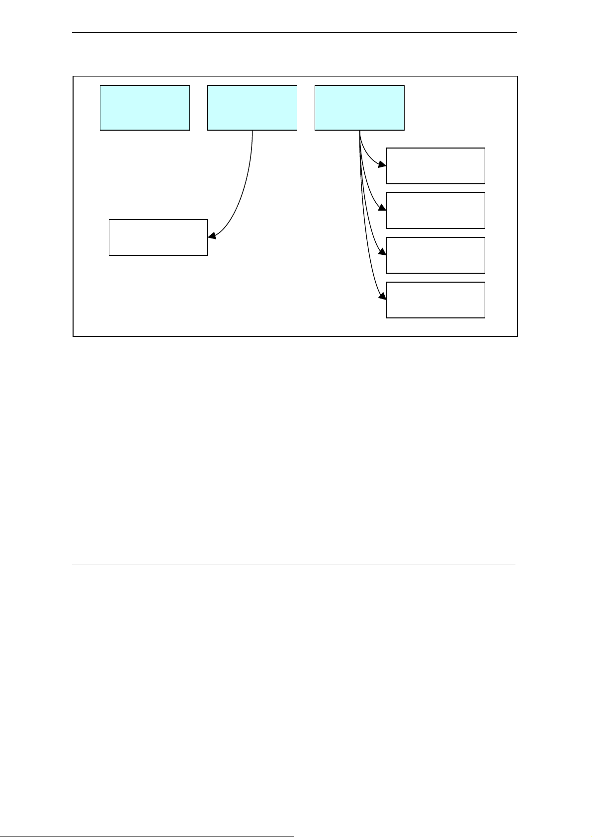
P964 APR has three major operation modes as shown in Figure 1-1.
Bridge
Mode
IP Sharing
Mode
Static IP
Mode
Basic Static IP
Static IP with
Public DHCP
Dynamic WAN
IP
Static IP with
AT O n ly
Static IP w/ NAT
and Private
Figure 1-1 Prestige 964 Operation Mode
1.3.1 Bridge Mode
In Bridge mode, P964 APR operates just like a normal cable modem/router. All operation is compliant to
DOCSIS specifications.
1.3.2 IP Sharing Mode
In IP Sharing mode, the P964 APR operates as a NAT router. It requires one public IP address from MSO’s
DHCP pool and provides private IP address space for LAN users. The public IP can be static assigned or
dynamically assigned through DHCP.
1.3.3 Static IP Mode
In Static IP mode, P964 APR provide a routed subnet on its Ethernet interface. A public IP subnet can be
assigned at the Ethernet interface such that the end user can have a static assigned subnet. At the same time,
the LAN users can also use private IP addresses to get on Internet.
1-2 Getting to Know Your P964 APR

Prestige 964 Cable Router with 802.11g Access Point
1.4 Key Features of the P964 APR
The following are the key features of the P964 APR:
DOCSIS 1.0/1.1/2.0 Compliant cable modem
Provides interoperability with other DOCSIS compliant cable modems and cable headend equipment.
Peak downstream signaling rates of 38Mbps and upstream signaling rates of 30 Mbps
Access the Internet with high performance network capability.
DOCSIS cable systems are capable of providing signaling rate of up to 43/55 Mbps and 30
Mbps for downstream and upstream respectively. This bandwidth however, is shared by
several subscribers because there are very few computers today that can connect to a
network at such high speeds. Hence, typical connection speeds are 5 Mbps downstream
and 1 Mbps upstream.
IP routing, TCP, ICMP, ARP, TFTP, RIP1, RIP2 with MD5
Improves network performance through containment of broadcast messages and improves security support for
unicast, broadcast and multicast IP packets. The RIP supports key-string encrypted with MD5 for
authentication with the CMTS.
4-port Auto-negotiating and Auto MDI/MDI-X 10/100 Mbps Ethernet Switch
The 4-port LAN interface automatically detects if it is on a 10 Mbps or a 100 Mbps Ethernet.
56-bit DES Baseline Privacy
Software Remotely Upgradeable
The software and configuration information is downloadable from the cable headend to the Prestige. This
eliminates the need for a cable technician's visit to install software upgrades.
Upgrade P964 APR Firmware via LAN
The firmware of the P964 APR can be upgraded via the LAN.
Built-in Diagnostic Features
P964 APR support remote troubleshooting via CMTS-initiated diagnostics, eliminating visit by a technician.
The front panel status indicator LEDs and web based status monitoring are also incorporated to easy
diagnostics from LAN interfaces.
SNMP
SNMP (Simple Network Management Protocol) is a protocol used for exchanging management information
between network devices. SNMP is a member of TCP/IP protocol suite. Your P964 APR supports SNMP agent
functionality, which allows a manager station to manage and monitor the P964 APR through the network. The
P964 APR supports SNMP version one, two and three.(SNMP v1, v2 and v3).
Network Address Translation (NAT)
NAT (Network Address Translation - NAT, RFC 1631) allows the translation of an Internet Protocol address
used within one network to a different IP address known within another network.
DHCP (Dynamic Host Configuration Protocol)
DHCP (Dynamic Host Configuration Protocol) allows the individual client computers to obtain the TCP/IP
configuration at start-up from a centralized DHCP server. The Prestige has built-in DHCP server capability,
Getting to Know Your P964 APR 1-3
Prestige 964 Cable Router with wireless Access Point
enabled by default, which means it can assign IP addresses, an IP default gateway and DNS servers to all
systems that support the DHCP client.
Web based Management & Configuration
The P964 APR supports web based management and configuration interface.
Text based configuration file
The P964 APR supports text based configuration file download and hence makes router deployment
simplified.
TACACS+ server support
The function allows access control to all interfaces for MSO to connect to TACACS+ server for telnet
authentication.
Predefined frequency band setting
This function assist the installation procedure by specifying predefined frequency band to accelerate the
downstream scanning at the first time the cable router is getting on line.
Hardware reset to factory default
The hardware reset button supports reset to factory default user name and password of user interfaces.
High throughput wireless data access
802.11g at 54Mbps ultra high wireless connectivity.
1.5 Product Specifications
Table 1-1~Table 1-Table 1-1 list the P964 APR specifications including the DOCSIS 2.0 standards and its
general specifications.
Table 1-1 DOCSIS Specifications
CLASS FEATURES
Operating Frequency 88MHz ~ 860MHz 5MHz ~ 42MHz
Modulation 64/256QAM QPSK or 8*/16/32*/64*/128*QAM or
Channel Width 6MHz 200/400/800/1600/3200/6400* kHz
Input Impedance 75 ohms Nominal 75 ohms Nominal
Maximum Data Rates 38.00 Mbps 30 Mbps**
Receive Input Level –15 dBmV to +15 dBmV
Transmission Output Power A-TDMA:
1-4 Getting to Know Your P964 APR
DOWNSTREAM UPSTREAM
QPSK
+8 dBmV ~ +54 dBmV (32/64QAM)

Prestige 964 Cable Router with 802.11g Access Point
CLASS FEATURES
+8 dBmV ~ +55 dBmV (8/16 QAM)
+8 dBmV ~ +58 dBmV (QPSK)
S-CDMA:
+8 dBmV ~ +53 dBmV (all modulation)
* With A-TDMA or S-CDMA enabled CMTS
** Speed of 30Mbps is attainable only with A-TDMA or S-CDMA technology.
Table 1-2 802.11g Access Point specifications
Frequency range 2.4~2.497GHz
Transmit power Typical 15dBm
Security & authentication
IEEE 802.1x, WPA, RADIUS support, SSID, MAC control
Data encryption AES, TKIP, 64/128bits WEP
Radio modulation
802.11g: OFDM with BPSK, QPSK, 16 QAM, 64 QAM
802.11b: CCK, DQPSK, DBPSK
Table 1-3 General Specifications
Number of LAN users Up to 253
Power Requirements 9V DC @1.5 Amps Max.
Operating Requirements
Dimensions 197(W) x 143(D) x 31(H) mm
Power Adapter 110/220V AC, 50~60 Hz
NOTE: To keep the P964 APR operating at optimal internal temperature, keep the bottom,
sides and rear of the P964 APR clear of obstructions and away from the exhaust of other
equipment. Don’t stack the P964 APR together in order to assure the safety.
Temperature: 0ºC to 40ºC (32ºF to 104ºF) (Please see NOTE)
Humidity: 5 % to 90 % (non-condensing)
7.76(W) x 5.63(D) x 1.22(H) inches
Getting to Know Your P964 APR 1-5


P964 APR Cable Router with 802.11g Access Point
Chapter 2
Hardware Installation and Initial Setup
This chapter shows the procedures for installing and starting the P964 APR.
2.1 Front Panel LEDs and Back Panel Ports
The P964 APR provides LEDs as status indicator for diagnostics purpose. The following figure and table
describe the functions of LEDs on the front panel of P964 APR :
Figure 2-1 P964 APR front panel
Table 2-1 P964 APR LED Functions
FUNCTION NAMING COLOR LED DESCRIPTION
Power PWR Green On: Power On
Off: Power Off
System SYS Green
or
Orange
LAN
link/activity
Hardware Installation 2-1
LAN 1~4 Green (10M)
or
Orange (100M)
On (Green): System ready and running successfully
On (Orange): System is loading the configuration
On (Green): System rebooting
Off: System not ready
On: LAN 1~4 Ethernet port link successful
Flashing: LAN 1~4 is Sending or Receiving
Off: LAN 1~4 Ethernet port not ready

P964 APR Cable Router with 802.11g Access Point
USB USB Green On: USB link successful
Flashing: Sending or Receiving
Off: USB not ready
WLAN WLAN Green On: WLAN link successful
Flashing: Sending or Receiving
Off: WLAN not ready
Cable data
activity
Cable link
status
DATA Green
CABLE Green On: The P964 APR is registered successfully with Cable
Flashing: WAN port (Cable Interface) TX/RX
Off: Connection is idle
Modem Terminal System (CMTS)
Slow Flash (2 seconds interval): The P964 APR is scanning
downstream channel
Fast Flash (1 second interval): The P964 APR is locked on to
downstream channel and is ranging and registering with CMTS
The SYS LED is always GREEN while system is ready or rebooting. The SYS LED will become
ORANGE when the system is loading its configuration. Don’t power off or reset your P964 APR
during the SYS LED is ORANGE. You can only power off or reset your P964 APR after the SYS LED
returns GREEN. Otherwise, your P964 APR will not work properly anymore.
.
The next figure shows the rear panel of your P964 APR and the connection diagram.
2-2 Hardware Installation

P964 APR Cable Router with 802.11g Access Point
Figure 2-2 P964 APR Rear Panel and Connections
2.2 Additional Installation Requirements
In addition to the contents of your package, there are other hardware and software requirements you need
before you can install and use your P964 APR. These requirements include:
1. You must have a network interface card (NIC), USB and WLAN interface supported on your computer
and configure the TCP/IP protocol stack properly.
2. An ISP account. Before installing your P964 APR, you need to establish an internet access account with
your local cable operator. They might ask for your cable router’s HFC MAC address and model number.
Please locate the MAC address at the back of your P964 APR.
NOTE: HFC MAC address can be found on the bar code sticker. Use the HFC MAC address
when registering with your cable company.
After the P964 APR is properly set up, you can make future changes to the configuration through telnet
connections. The Telnet configuration will be introduced later on.
Hardware Installation 2-3

P964 APR Cable Router with 802.11g Access Point
2.2.1 Setting up Your Windows 95/98/Me Computer
Installing TCP/IP Components
1. Click Start, Settings, Control Panel and double-click the Network icon.
2. The Network window Configuration tab displays a list of installed components.
To install TCP/IP:
a. In the Network window, click Add.
b. Select Protocol and then click Add.
c. Select Microsoft from the list of manufacturers.
d. Select TCP/IP from the list of network protocols and then click OK.
Configuring TCP/IP
1. In the Network window Configuration tab, select your network adapter’s TCP/IP entry and click
Properties.
2. Click the IP Address tab. Click Obtain an IP address automatically.
3. Click the DNS Configuration tab. Select Disable DNS.
4. Click the Gateway tab. Highlight any installed gateways and click Remove until there are none listed.
5. Click OK to save and close the TCP/IP Properties window.
6. Click OK to close the Network window.
7. Turn on your Prestige and restart your computer when prompted. Insert the Windows CD if prompted.
Verifying TCP/IP Properties
1. Click Start and then Run. In the Run window, type "winipcfg" and then click OK to open the IP
Configuration window.
2. Select your network adapter. You should see your computer's IP address, subnet mask and default
gateway.
2.2.2 Setting up Your Windows NT/2000/XP Computer
Configuring TCP/IP
1. Click Start, Settings, Network and Dial-up Connections and right-click Local Area Connection or the
connection you want to configure and click Properties. For Windows XP, click start, Control Panel,
Network and Internet Connections and then Network Connections. Right-click the network
connection you want to configure and then click Properties.
2. Select Internet Protocol (TCP/IP) (under the General tab in Win XP) and click Properties.
3. The Internet Protocol TCP/IP Properties window opens. Click Obtain an IP address automatically.
4. Click Obtain DNS server automatically.
5. Click Advanced, IP Settings tab and remove any installed gateways, then click OK.
6. Click OK to save and close the Internet Protocol (TCP/IP) Properties window.
2-4 Hardware Installation

P964 APR Cable Router with 802.11g Access Point
7. Click OK to close the Local Area Connection Properties window.
8. Turn on your Prestige and restart your computer (if prompted).
Verifying TCP/IP Properties
1. Click Start, Programs, Accessories and then Command Prompt.
2. In the Command Prompt window, type "ipconfig" and then press ENTER. The window displays
information about your IP address, subnet mask and default gateway.
2.2.3 Setting up Your Macintosh Computer
Configuring TCP/IP Properties
1. Click the Apple menu, Control Panel and double-click TCP/IP to open the TCP/IP Control Panel.
2. Select Ethernet from the Connect via list.
3. Select Using DHCP Server from the Configure list.
4. Close the TCP/IP Control Panel.
5. Click Save if prompted, to save changes to your configuration.
6. Turn on your Prestige and restart your computer (if prompted).
Verifying TCP/IP Properties
Check your TCP/IP properties in the TCP/IP Control Panel.
2.3 Factory Default Settings
The P964 APR is configured as a IP sharing router with NAT and DHCP enabled and with following
factory default.
Table 2-2 P964 APR factory default
Items Settings
LAN IP Address 192.168.1.1
Subnet Mask 255.255.255.0
DHCP IP Pool 192.168.1.33 – 192.168.1.64
Web user username user
Web user password 1234
Hardware Installation 2-5

P964 APR Cable Router with 802.11g Access Point
The default might be different from different cable operators. Please consult with your cable Internet
service provider for any change.
2.4 Initializing the Cable Sharing Gateway
This section outlines how to connect your P964 APR to the LAN and the cable network.
Step 1. Preparing the CATV Coaxial Cable Connection
Locate the coaxial cable at the installation site and move the cable end, or install a two-way splitter as
necessary to provide a connection near the P964 APR cable modem location.
Step 2. Connecting the P964 APR to the Cable System
Connect the P964 APR to the cable port using an F-type connector. (If the quality or general condition of the
coaxial cable at the installation site is in question, we recommended that you replace the coaxial cable). The
cable port on the P964 APR is labeled "CABLE”.
Step 3. Connecting Ethernet Cable(s) or USB cable to the P964 APR
If you do not have an Ethernet interface card (NIC) in your computer, please install one or use the USB
connectivity. The Ethernet interface of your P964 APR support 10/100M auto-negotiating and auto
MDI/MDI-X function. You can use any type of Ethernet cable to connect it to your computer directly or
through an external switch/hub.
Step 4. Connecting the Power Adapter to your P964 APR
Connect the power adapter to the port labeled POWER on the rear panel of your P964 APR.
Step 5. P964 APR Initialization
The P964 APR is powered on whenever you connect the power adapter to the power outlet. It will initialize the
system and start to connect with headend CMTS. When the CABLE LED shines steadily, the P964 APR is
ready to handle data traffic. The first initialization process might take several minutes because it will scan for
the proper downstream and upstream channels. When the P964 APR is ready, it will memorize the channel
attributes. If you power cycle the P964 APR, the next connection process will be faster.
2.5 Network Configuration of Your Computer
You must have a network interface card installed on your computer and configure the TCP/IP protocol stack
properly. For Windows® 95/98/NT/2000, please configure your computer as a DHCP client. The IP address
identifies the computer on the network and enables the headend CMTS to route data to and from your
computer.
For Windows
For Windows® NT/XP/2000, you can use the following command to verify the TCP/IP configuration.
2-6 Hardware Installation
®
95/98, you can use the following command to verify the TCP/IP configuration.
Winipcfg
Ipconfig

P964 APR Cable Router with 802.11g Access Point
2.6 Router Configuration
You do not need to ask your cable company for a special configuration. The P964 APR can act as a DHCP
client to acquire an IP address from the headend. Besides, it can act as a DHCP server at the LAN port and
assign an IP address to your computers on the LAN subnet. What you have to do is to configure the LAN port
with the proper IP address and netmask. If you already have a DHCP server on your LAN subnet, you can
disable the DHCP server in the P964 APR but you have to assign an IP address/netmask for the LAN port.
2.7 Power On Your P964 APR
You should connect at least one of the LAN,USB port to your computer. Connect the cable port and the power
port to the appropriate devices . Plug the power adapter into a wall outlet When connected, it is powered on,
the P964 APR executes an automatic installation procedure:
1. Scans and locks on to the service provider’s downstream frequency.
2. Obtains timing, signal, power level, authentication, addressing, and other operational parameters from
the headend CMTS.
3. Downloads its configuration file and is then operational.
During the initialization, the LEDs on the P964 APR turns on:
1. The Power LED should be ON.
2. The CABLE LED will flash with a 2 seconds duration while scanning the downstream channel. When it
has locked on to a downstream channel and is communicating with the headend CMTS, the CABLE
LED will flash with a 1 second duration. Once the cable connection is completed, it will remain “ON”. It
may need 40 seconds from step 1 to step 2..
3. The DATA LED flashes when the P964 APR is receiving or transmitting data through the coaxial cable.
It is OFF when no data is transferred.
4. Depending on which port is connected successfully, the LAN (1~4) LED , WLAN, or the USB LED will
be “ON” and flashing while sending/receiving data to/from your computer/laptop.
After the initial setup and P964 APR is powered on, you can modify the configuration remotely through telnet
connections.
Please note that if there is no activity for longer than 3 minutes after you log in, your P964 APR will
automatically log you out.
Hardware Installation 2-7


P964 APR Cable Router with 802.11g Access Point
Chapter 3
Web Based Management
This chapter describes the web based management & configuration interface.
3.1 Introduction
Before accessing the P964 APR web pages, follow the procedures below to set up your Windows NT/2000/XP
Computer Configuring TCP/IP
1. Click Start, Settings, Network and Dial-up Connections and right-click Local Area Connection or the
connection you want to configure and click Properties. For Windows XP, click start, Control Panel,
Network and Internet Connections and then Network Connections. Right-click the network
connection you want to configure and then click Properties.
2. Select Internet Protocol (TCP/IP) (under the General tab in Win XP) and click Properties.
3. The Internet Protocol TCP/IP Properties window opens. Click Obtain an IP address automatically.
4. Click Use the following IP address
5. Set the IP address as 192.168.1.x, where x represents any number between 10 to 30.
6. Set the net mask as 255.255.255.0
7. Click Advanced, IP Settings tab and remove any installed gateways, then click OK.
8. Click OK to save and close the Internet Protocol (TCP/IP) Properties window.
9. Click OK to close the Local Area Connection Properties window.
Verifying TCP/IP Properties
10. Click Start, Programs, Accessories and then Command Prompt.
11. In the Command Prompt window, type "ipconfig" and then press ENTER. The window displays
information about your IP address, subnet mask and default gateway.
Web Based Management 3-1

P964 APR Cable Router with 802.11g Access Point
After you have finished the TCP/IP configuration setup, You may access the web pages by typing the web
address
The P964 APR cable router provides users to configure LAN settings including DHCP server IP, netmask,
DHCP clients’ start IP address and the number of CPEs. To configure the LAN setting, users use a PC to
browse the LAN IP of the cable router. The web functions only open to the LAN, no access from HFC cable is
allowed. When browsing started, the cable router prompts the following windows for user to login.
” http://192.168.1.1:8080/”.
Figure 3-1 Web Management – “User Login” Page
After input username/password, click “OK” and the following page will be displayed.
There are four tags “Status”, “Basic”, “Advanced” and “wireless” as shown in in the web management
interface of P964APR. The “Status” tag will show the connection status and software information. “Basic” and
“Advanced” tags are used for the configuration to LAN interface.
1. “Status”
The “Status” tag will show the connection status, software information and event logs of your P964APR.
2. “Basic”
Click “Basic”, users can set DHCP server IP, and net mask, etc.
3. “Advanced”
This function is designed especially for users who want more control of LAN interface. For example,
users can block packet from some CPEs to access the Internet. Users can also open some well known
ports or some special port for accessing from the Internet.
4. “Wireless”
Users can configure the wireless access point by clicking the “wireless” tag. There are four groups of
configuration setups in the “Wireless” tag.
3-2 Web Based Management

3.2 “Status” Page
P964 APR Cable Router with 802.11g Access Point
Figure 3-2 Web Management - Status
The “Connection” icon in Figure 3-2 shows the connection status of the cable router. Users can also click the
“Software” icon in this page to show the software information of the box .
Web Based Management 3-3

P964 APR Cable Router with 802.11g Access Point
3.3 “Basic” Page
When click “Basic” tag, the following page is displayed.
Figure 3-3 Web Management - Basic
From the “Basic” page, users can set the DHCP server IP for the LAN as well as the network, netmask,
DHCP’s starting IP, and the number of CPEs. User can also set lease time for the CPEs. But to update these
above settings may prevent users from accessing Internet. Do not update it unless you can handle it. Besides,
the password for user privilege to logon to the web based management interface can be changed in this page.
Type the same password as Password field in the Re-Enter Password to double confirm new user
password. After finish the configuration, click “Apply” icon to save the settings.
3.4 “Advanced” Page
The “Advanced” is a powerful tool to set more advanced features for the P964 APR. When click the
3-4 Web Based Management

P964 APR Cable Router with 802.11g Access Point
“Advanced” tag, there are 6 functions as shown in the following picture:
Figure 3-4 Web Management – Advanced: Options
3.4.1 Web Management – Advanced: Options
The “Option” icon allows users to configure advanced features of the P964 APR.
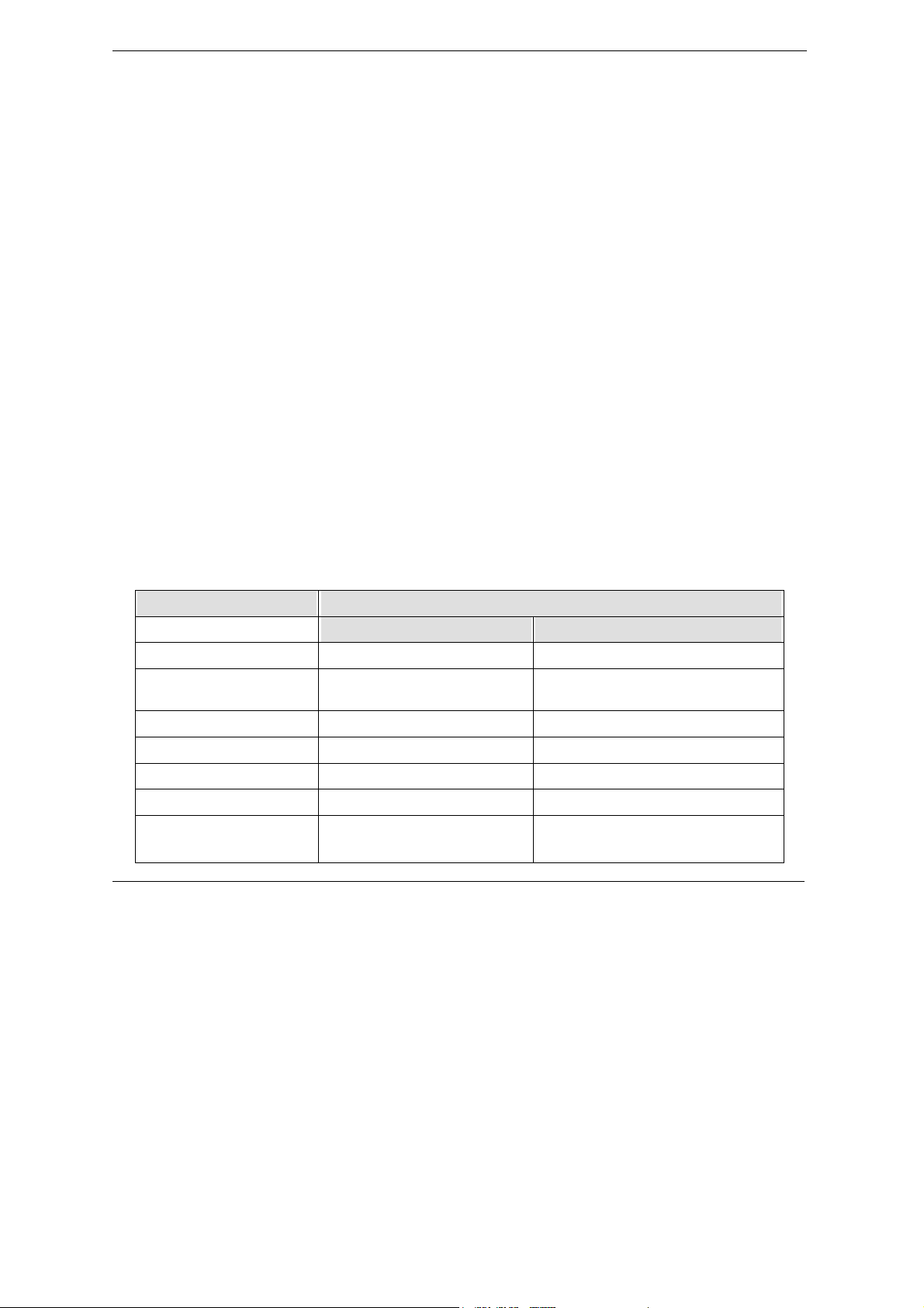
Table 3-1 Web Management – Advanced: Options
Function Description
WAN Blocking Do not response to some ICMP’s probing packets, e.g. ping, traceroute and
etc.
IPsec PassThrough Allow users to execute IPSec VPN client in the workstations
PPTP PassThrough Allow users to execute PPTP client in the workstations
Multicast Enable Allows users to enable or disable multicast IGMP protocol
After finishing the configuration, click “Apply” icon to save the settings.
Web Based Management 3-5

P964 APR Cable Router with 802.11g Access Point
3.4.2 Web Management – Advanced: IP Filtering
The “IP Filtering” in the “Advanced” page allows users to configure IP address filters in order to block
Internet traffic to specific network devices on the LAN. Click “IP Filtering” icon, the window is shown as
below:
Figure 3-5 Web Management – Advanced: IP Filtering
Users can block specific CPEs to access the Internet. For example, there is a CPE with “192.168.10.20” IP
address, users can set it as ”enabled” in the above window and click “Apply” icon to save the settings. The
CPE can not access the Internet after the IP filtering settings is completed.
3.4.3 Web Management – Advanced: MAC Filtering
“MAC Filtering” allows configuration of MAC address filters in order to block Internet traffic to specific
network devices on the LAN. Click “MAC Filtering” icon, the screen is displayed.
3-6 Web Based Management

P964 APR Cable Router with 802.11g Access Point
Figure 3-6 Web Management – Advanced: MAC Filtering
Users can block specific CPEs to access the Internet. It has the same effect as “IP Filtering” except this
function use MAC address instead of IP address. After finish the configuration, click Apply button to save the
settings.
3.4.4 Web Management – Advanced: Port Filtering
“Port Filtering” allows configuration of port filters in order to block specific Internet services to all devices on
the LAN. Click “Port Filtering” icon, the screen is displayed.
Web Based Management 3-7

P964 APR Cable Router with 802.11g Access Point
Figure 3-7 Web Management – Advanced: Port Filtering
The “Port Filtering” control CPEs not to access the Internet to get the services which is provided through the
ports. After finish the configuration, click Apply button to save the settings.
3.4.5 Web Management – Advanced: Forwarding
The “Forwarding” page allows incoming requests on specific port numbers to reach web servers, FTP servers,
mail servers, etc. so they can be accessible from the public Internet. Click “Forwarding” icon, the screen is
shown as below.
3-8 Web Based Management

P964 APR Cable Router with 802.11g Access Point
Figure 3-8 Web Management – Advanced: Forwarding
Set the local IP address on your LAN in the Local IP Adr field to allow for port number from the Start Port
field to the End Port field to be accessed in the station. The Protocol field allows you to decide the port
attribute from TCP/UDP/Both. A table of commonly used port numbers is also provided on the right side of
this page. After finish the configuration, click Apply button to save the settings.
Web Based Management 3-9

P964 APR Cable Router with 802.11g Access Point
3.4.6 Web Management – Advanced: Port Triggers
This “Port Triggers” function allows user to configure dynamic triggers for specific devices on the LAN. This
allows applications required specific port numbers with bi-directional traffic to function properly. Applications
such as video conferencing, voice, gaming, and some messaging program may require these special settings.
Figure 3-9 Web Management – Advanced: Port Triggers
After finishing the configuration setup, click Apply button to save the settings.
3-10 Web Based Management

P964 APR Cable Router with 802.11g Access Point
3.4.7 Web Management – Wireless: Configuration setup for Access Point
There are four groups of configuration setups in the “Wireless” tag. The following pages describe the detailed
function of each group.
3.4.7.1 Wireless: 802.11b/g Basic
The “802.11b/g Basic” allows users to setup wireless configuration of the Access Point, It includes the
parameter settings of SSID and channel number.
Figure 3-10 Web Management – Wireless: 802.11b/g Basic
Network Name (SSID):
“SSID” is an ASCII string up to 32 characters. 802.11b/ g client adapters must have the same ID to
connect to P964 APR.
Network Type :
Selecting “Open”(default) causes the P964 APR to broadcast system SSID, wireless mobile users can
see the P964 APR and join this group. In order to prevent this unwanted situation, choose “close” to
Web Based Management 3-11

P964 APR Cable Router with 802.11g Access Point
disable the SSID broadcasting function.
Country:
P964 APR supports the following channel for each country. The default setting is “USA”.
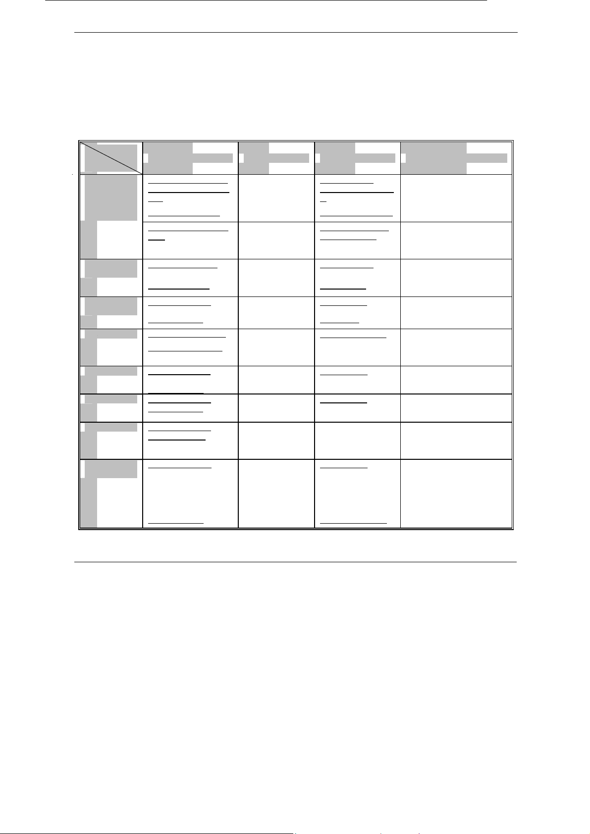
Worldwide 1 ~ 13 Jordan 10 ~ 13 USA 1 ~ 11
Thailand 1 ~ 14 China 1 ~ 13 Europe 1 ~ 13
Israel 5 ~ 7 Japan 1 ~ 14 All channels 1 ~ 14
Channel:
After setting the country option, you can assign channel number for each country.
Its default channel number is “1”.
Interface:
With this option , you may enable or disable the wireless interface card. The default setting is “Enabled”.
Click “Apply” button to save the settings.
3.3.7.2 Wireless: 802.11b/g Privacy
Click the “Security” icon, the “802.11b/g Privacy” allows users to setup wireless configuration of the WEP
keys and/or pass phrase.
Network Authentication:
The Prestige 964 wireless AP supoorts the following authentications.
“Disabled”: This is the default value. When “Disabled” is chosen, users can set “Data Encryption” as
‘Off’, ‘WEP(64-bit)’ or ‘(WEP)128-bit’.
The “Shared Key Authentication” can be set as ‘Optional’ or ‘Required’. If “Shared Key Authentication”
is set as ‘Optional’, users will be requested to enter the “PassPhrase” when connecting. If “Shared Key
Authentication” is set as ‘Required’, users also need to set the same “Network Key” and “Current
Network Key” to connect the AP. You can use “Generate WEP Keys” to set the “Network Key”. The
802.11b/ g client devices must have the same settings to connect with P964 APR.
“802.1x”: There must be a RADIUS server when use this setting. 802.11b/g client devices must have a
relative setting for this option. It is also required to set the correct “PassPhrase” on RADIUS server
while connecting with P964 APR.
“WPA”: This option has the same requirement to set the RADIUS server. 802.11b/g client devices must
support WPA option to connect with P964 APR.
“WPA-PSK”: The RADIUS server is not required, but the “WPA Pre-Shared Key” must be set. In order
to connect with P964 APR, 802.11b/g client devices must support WPA option. The P964 APR also has a
3-12 Web Based Management

P964 APR Cable Router with 802.11g Access Point
“WPA Group Rekey Interval” setting, the unit is in seconds, It is a function for WPA key changeing
periodically by setting the interval.
Click “Apply” to Save all change.
Figure 3-11 Web Management – Wireless: Security
The “802.11b/g Access Control” allows user to configure the Access Control of the AP and the connected
clients.
Web Based Management 3-13

P964 APR Cable Router with 802.11g Access Point
“MAC Restrict Mode”: The restrict mode can be set as ‘Allow’ or ‘Deny’ to allow or deny access client to
connect the P964 APR. Choose ‘Disabled’ without any restrictions.
“MAC Addresses”: MAC Addresses to ‘Deny’ or ‘Allow’
Click “Apply” to Save all change.
“Connected Clients”: Show the current connecting CPEs.
Figure 3-12 Web Management – Wireless: Access Control
The “802.11b/g Advanced” allows user to configure data rates and WiFi thresholds.
“54g Network Mode”:
3-14 Web Based Management

P964 APR Cable Router with 802.11g Access Point
Max Compatibility - supports 802.11b/g clients
54g Only - supports only 802.11g clients
Max performance - supports only 802.11g clients and uses a proprietary method of improving
performance. This mode may not work with all 802.11g clients.
“54g Protection”:
54g Protection is a mechanism that is created for
using RTS/CTS to maximize the throughput in mixed 802.11b/g networks. When
set to 'Auto', it will use this method to maximize throughput. If the
network only contains 802.11g clients, set this to off to maximize 11g
performance. Mixed networks have an issue where a 11b client is not able to
determine that a 11g client is transmitting so it will transmit anyway and
squash the g transmission. The 54g protection will keep 11b clients from using
too much bandwidth by determining when they can transmit so not to interfere
with 11g clients.
“Rate”:
Auto / 1.0 Mbps / 2.0 Mbps / 5.5 Mbps / 6.0 Mbps / 9.0 Mbps / 11.0 Mbps / 12.0 Mbps / 18.0 Mbps /
24.0 Mbps / 36.0 Mbps / 48.0 Mbps / 54.0 Mbps
“Output Power”:
25% / 50% / 75% / 100%
“DTIM Interval”:
DTIM interval - A DTIM interval, also known as a Data Beacon Rate, is the frequency at which an
access point's beacon will include a DTIM. This frequency is usually measured in milliseconds (ms).
DTIM - Delivery Traffic Indication Message. A DTIM is a signal sent as part of a beacon by an access
point to a client device in sleep mode, alerting the device to a packet awaiting delivery.
“Fragmentation Threshold”:
Fragmentation Threshold - This set the threshold at which wireless packets
will be fragmented. This can be used to improve throughput when RF
interference is causing poor throughput.
“RTS Threshold”:
RTS - Request To Send. An RTS is a message sent by a networked device to its access point, seeking
permission to send a data packet. RTS threshold - Request To Send threshold. The RTS threshold
specifies the packet size of an RTS transmission. This helps control traffic flow through an access point,
especially one with many clients. The setting normally does not need to be changed
Click “Apply” to Save all change.
Web Based Management 3-15

P964 APR Cable Router with 802.11g Access Point
Figure 3-13 Web Management – Wireless: Advanced
3-16 Web Based Management

P964 APR Cable Router with 802.11g Access Point
Chapter 4
Troubleshooting
This chapter covers the potential problems you may run into and the possible remedies. After each
problem description, some instructions are provided to help you to diagnose.
4.1 Problems with Cable Connection
Table 4-1 Troubleshooting for the link failure
PROBLEM CORRECTIVE ACTION
The PWR LED is off.
The SYS LED is off.
LAN (1~4) LED and USB
LED are OFF.
WLAN LED is OFF Ensure the WLAN port setting of your NB or PC is ok. Make sure the SSID of your
Make sure that the power adaptor is connected to the
an appropriate power source. Check that the power source is turned on.
If the error persists, you may have a hardware problem. In this case, you should
contact your cable operator.
Turn the
Check the LAN/USB LEDs on the front panel. One of these LEDs should be on. If
they are all off, check the Ethernet cables between your P964 APR and hub/station
or the USB cable ace on your station.
NB or PC is same as that of your P964 APR, if the situation persists, call ZyXEL for
technical support.
P964 APR power off and then on again.
P964 APR and plugged in to
4.2 Problems with Internet Access
Table 4-2 Troubleshooting for the Internet Access
PROBLEM CORRECTIVE ACTION
Cannot access e-mail
or Internet Service.
Troubleshooting 4-1
Make sure that the coaxial cable is connected to the P964 APR and the Internet.
Check with your service provider to see if your account has been activated.
Check if your computer’s network configuration is correct. For a dynamic IP address
assignment, you have to activate your computer’s DHCP client. And, you might need
to assign a DNS server address. Refer to cable operator’s configuration information.
Check your TCP/IP parameters and verify that you have installed TCP/IP
properly. If the problem persists, call your cable service provider to verify that
their service is two-way and DOCSIS compliant.

P964 APR Cable Router with 802.11g Access Point
All of the LEDs are ok,
but I still cannot access
the Internet.
If the LEDs are correct, then your P964 APR is operating properly. Try
shutting down, powering off your computer and then turning it on again. This
will cause your computer to re-establish communication with P964 APR.
Check your TCP/IP parameters and verify that you have installed TCP/IP
properly.
4-2 Troubleshooting

P964 APR Cable Router with 802.11g Access Point
Appendix A
Hardware Specifications
Power Specification Input: AC 110/220, 50/60Hz; Output: DC 9V
Operation Temperature 0º C ~ 40º C
Cable Specification for
WAN/Internet
Ethernet Specification for LAN 10/100Mbit Half / Full Auto-negotiation and Auto MDI/MDI-X
USB Interface Specification USB 1.1
LAN Cable Pin Layout:
Straight-Through
(Switch)
1 IRD +
2 IRD - 2 OTD - 2 IRD - 2 IRD -
3 OTD + 3 IRD + 3 OTD + 3 OTD +
6 OTD - 6 IRD - 6 OTD - 6 OTD -
Female “F” Type RF Connector
Crossover
(Adapter)
1 OTD +
(Switch)
1 IRD +
(Switch)
1 IRD +
Hardware Specifications A


P964 APR Cable Router with 802.11g Access Point
Appendix B
Important Safety Instructions
The following safety instructions apply to the P964 APR:
Be sure to read and follow all warning notices and instructions. Care must be taken to allow sufficient air
circulation or space between units when the P964 APR is installed inside a closed rack assembly. The
operating ambient temperature of the rack environment might be greater than room temperature. The
maximum recommended ambient temperature for the P964 APR is 40ºC (104ºF). Installation in a rack without
sufficient airflow can be unsafe. Racks should safely support the combined weight of all equipment.
The connections and equipment that supply power to the P964 APR should be capable of operating safely with
the maximum power requirements of the P964 APR. In case of a power overload, the supply circuits and
supply wiring should not become hazardous. The input rating of the P964 APR is printed on the nameplate.
The AC adapter must plug in to the right supply voltage, i.e. 120VAC adapter for North America and 230VAC
adapter for Europe. Make sure that the supplied AC voltage is correct and stable. If the input AC voltage is
over 10% lower than the standard may cause the P964 APR to malfunction.
Installation in restricted access areas must comply with Articles 110-16, 110-17, and 110-18 of the National
Electrical Code, ANSI/NFPA 70.
Do not allow anything to rest on the power cord of the AC adapter, and do not locate the product where
anyone can walk on the power cord. Do not service the product by yourself. Opening or removing covers can
expose you to dangerous high voltage points or other risks. Refer all servicing to qualified service personnel.
Generally, when installed after the final configuration, the product must comply with the applicable safety
standards and regulatory requirements of the country in which it is installed. If necessary, consult the
appropriate regulatory agencies and inspection authorities to ensure compliance.
A rare condition can create a voltage potential between the earth grounds of two or more buildings. If products
installed in separate building are interconnected, the voltage potential can cause a hazardous condition. Consult
a qualified electrical consultant to determine whether or not this phenomenon exists and, if necessary,
implement corrective action before interconnecting the products. If the equipment is to be used with
telecommunications circuit, take the following precautions:
Never install wiring during a lightning storm.
Never install jacks in wet location unless the jack is specially designed for wet location.
Never touch uninsulated wires or terminals unless the line has been disconnected at the network interface.
Use caution when installing or modifying lines during an electrical storm. There is a remote risk of electric
shock from lightning.
Safety Instructions C


P964 APR Cable Router with 802.11g Access Point
Glossary of Terms
10BaseT
ARP
Authenticity Proof that the information came from the person or location that reportedly sent it. One example
Back Door A deliberately planned security breach in a program. Back doors allow special access to a
Backbone A high-speed line or series of connections that forms a major pathway within a network.
BackOrifice BackOrifice is a remote administration tool which allows a user to control a
Bandwidth This is the capacity on a link usually measured in bits-per-second (bps).
Bit (Binary Digit) -- A single digit number in base-2, in other words, either a 1 or a zero. The
Brute Force Hacking A technique used to find passwords or encryption keys. Force Hacking involves trying every
The 10-Mbps baseband Ethernet specification that uses two pairs of twisted-pair cabling
(Category 3 or 5): one pair for transmitting data and the other for receiving data.
Address Resolution Protocol is a protocol for mapping an Internet Protocol address (IP address) to
a physical machine address that is recognized in the local network.
of authenticating software is through digital signatures.
computer or program. Sometimes back doors can be exploited and allow a cracker unauthorized
access to data.
computer across a TCP/IP connection using a simple console or GUI application. BackOrifice is
a potentially disastrous Trojan horse since it can provide the user unlimited access to a system.
smallest unit of computerized data.
possible combination of letters, numbers, etc. until the code is broken.
Byte A set of bits that represent a single character. There are 8 bits in a Byte.
Cable Modem (CM)
Camping Out Staying in a "safe" place once a hacker has broken into a system. The term
CATV Cable TV system. Can be all coaxial- or HFC- (Hybrid Fiber Coax) based.
CDR Call Detail Record. This is a name used by telephone companies for call related information.
Channel
CHAP Challenge Handshake Authentication Protocol is an alternative protocol that avoids sending
A cable modem is a device that enables you to hook up your computer to a local cable TV line
and receive data at about 1.5 Mbps. This data rate far exceeds that of the prevalent 28.8 and 56
Kbps telephone modems, and up to 128 Kbps of ISDN that is about the data rate available to
subscribers of Digital Subscriber Line (DSL) telephone service. A cable modem can be added to
or integrated with a set top box that turns your TV set into an Internet channel. For computer
attachment, the cable line must be split so that part of the line goes to the TV set and the other
part goes to the cable modem and the computer.
A cable modem is more like a network interface card (NIC) than a computer modem. All of the
cable modems attached to a cable TV company coaxial cable line communicate with a Cable
Modem Termination System (CMTS) at the local cable TV company office. All cable modems
can receive only from and send signals to the CMTS, but not to other cable modems on the line.
can be used with a physical location, electronic reference, or an entry point for future attacks.
A specific frequency and bandwidth combination. In the present context, it means TV channels
for television services and downstream data for cable modems.
passwords over the wire by using a challenge/response technique.
Glossary E

P964 APR Cable Sharing Gateway with 4-port Switch
Cipher Text Text that has been scrambled or encrypted so that it cannot be read without deciphering it. See
Encryption
Client A software program that is used to contact and obtain data from a Server software program on
another computer. Each Client program is designed to work with one or more specific kinds of
Server programs, and each Server requires a specific kind of Client. A Web Browser is a specific
kind of Client.
CMTS
Cookie A string of characters saved by a web browser on the user's hard disk. Many web pages send
Countermeasures Techniques, programs, or other tools that can protect your computer against threats.
CPE
Cracker Another term for hackers. Generally, the term cracker refers specifically to a person who
Cracker Tools Programs used to break into computers. Cracker tools are widely
Cracking The act of breaking into computers or cracking encryptions.
Crossover Ethernet
cable
Cryptoanalysis The act of analyzing (or breaking into) secure documents or systems that are protected with
CSU/DSU Channel Service Unit/Data Service Unit. CSUs (channel service units) and DSUs (data service
DCE Data Communications Equipment is typically a modem or other type of communication device.
Decryption The act of restoring an encrypted file to its original state.
Denial of Service Act of preventing customers, users, clients or other machines from
DHCP
Cable Modem Termination System. A central device for connecting the cable TV network to a
data network like the Internet. Normally it is placed in the headend of the cable TV system.
cookies to track specific user information. Cookies can be used to retain information as the user
browses a web site. For example, cookies are used to 'remember' the items a shopper may have in
a shopping cart.
Customer Premises Equipment. Used to describe the computer and/or other equipment that the
customer may want to connect to the cable modem.
maliciously attempts to break encryption, software locks, or network security.
distributed on the Internet. They include password crackers, Trojans, viruses, war-dialers, and
worms.
A cable that wires a pin to its opposite pin, for example, RX+ is wired to TX+. This cable
connects two similar devices, for example, two data terminal equipment (DTE) or data
communications equipment (DCE) devices.
encryption.
units) are actually two separate devices, but they are used in conjunction and often combined into
the same box. The devices are part of the hardware you need to connect computer equipment to
digital transmission lines. The Channel Service Unit device connects with the digital
communication line and provides a termination for the digital signal. The Data Service Unit
device, sometimes called a digital service unit, is the hardware component you need to transmit
digital data over the hardware channel. The device converts signals from bridges, routers, and
multiplexors into the bipolar digital signals used by the digital lines. Multiplexors mix voice
signals and data on the same line.
The DCE sits between the DTE (data terminal equipment) and a transmission circuit such as a
phone line.
accessing data on a computer. This is usually accomplished by interrupting or overwhelming the
computer with bad or excessive information requests.
F Glossary

P964 APR Cable Router with 802.11g Access Point
log on. DHCP centralizes IP address management on central computers that run the DHCP server
program. DHCP leases addresses for a period of time which means that addresses are made
available to assign to other systems.
Digital Signature Digital code that authenticates whomever signed the document or software. Software, messages,
Email, and other electronic documents can be signed electronically so that they cannot be altered
by anyone else. If someone alters a signed document, the signature is no longer valid. Digital
signatures are created when someone generates a hash from a message, then encrypts and sends
both the hash and the message to the intended recipient. The recipient decrypts the hash and
original message, makes a new hash on the message itself, and compares the new hash with the
old one. If the hashes are the same, the recipient knows that the message has not been changed.
Also see Public-key encryption.
DNS Domain Name System. A database of domain names and their IP addresses. DNS is the primary
naming system for many distributed networks, including the Internet.
DOCSIS
Domain Name The unique name that identifies an Internet site. Domain Names always have 2 or more parts,
Downstream
Downstream
Frequency
DRAM Dynamic RAM that stores information in capacitors that must be refreshed periodically.
DTE Originally, the DTE (data terminal equipment) meant a dumb terminal or printer, but today it is a
EMI ElectroMagnetic Interference. The interference by electromagnetic signals that can cause reduced
Encryption The act of substituting numbers and characters in a file so that the file is unreadable until it is
Data over Cable Service Interface Specification. It is the dominating cable modem standard,
which defines technical specifications for both cable modem and CMTS.
separated by dots. The part on the left is the most specific, and the part on the right is the most
general.
The data flowing from the CMTS to the cable modem.
The frequency used for transmitting data from the CMTS to the cable modem. Normally in the
42/65-850 MHz range depending on the actual cable plant capabilities.
computer, or a bridge or router that interconnects local area networks.
data integrity and increased error rates on transmission channels.
decrypted. Encryption is usually done using a mathematical formula that determines how the file
is decrypted.
Ethernet A very common method of networking computers in a LAN. There are a number of adaptations
to the IEEE 802.3 Ethernet standard, including adaptations with data rates of 10 Mbits/sec and
100 Mbits/sec over coaxial cable, twisted-pair cable, and fiber-optic cable. The latest version of
Ethernet, Gigabit Ethernet, has a data rate of 1 Gbit/sec.
Events These are network activities. Some activities are direct attacks on your system, while others
might be depending on the circumstances. Therefore, any activity, regardless of severity is called
an event. An event may or may not be a direct attack on your system.
FAQ (Frequently Asked Questions) -- FAQs are documents that list and answer the most common
questions on a particular subject.
FCC The FCC (Federal Communications Commission) is in charge of allocating the electromagnetic
spectrum and thus the bandwidth of various communication systems.
Firewall A hardware or software "wall" that restricts access in and out of a network. Firewalls are most
often used to separate an internal LAN or WAN from the Internet.
Glossary G

P964 APR Cable Sharing Gateway with 4-port Switch
Flash memory The nonvolatile storage that can be electrically erased and reprogrammed so that data can be
stored, booted, and rewritten as necessary.
FTP File Transfer Protocol is an Internet file transfer service that operates on the Internet and over
TCP/IP networks. FTP is basically a client/server protocol in which a system running the FTP
server accepts commands from a system running an FTP client. The service allows users to send
commands to the server for uploading and downloading files. FTP is popular on the Internet
because it allows for speedy transfer of large files between two systems.
Gateway A gateway is a computer system or other device that acts as a translator between two systems that
do not use the same communication protocols, data formatting structures, languages, and/or
architecture.
Hacker Generally, a hacker is anyone who enjoys experimenting with technology including computers
and networks. Not all hackers are criminals breaking into systems. Some are legitimate users and
hobbyists. Nevertheless, some are dedicated criminals or vandals.
HDLC HDLC (High-level Data Link Control) is a bit-oriented (the data is monitored bit by bit), link
layer protocol for the transmission of data over synchronous networks.
Headend
HFC
Host Any computer on a network that is a repository for services available to other computers on the
HTTP Hyper Text Transfer Protocol. The most common protocol used on the Internet. HTTP is the
Central distribution point for a CATV system. Video signals are received here from satellites and
maybe other sources, frequency converted to the appropriate channels combined with locally
originated signals and rebroadcast onto the HFC plant. The headend is where the CMTS is
normally located.
HFC (hybrid fiber coaxial cable) is a telecommunication technology in which fiber optic cable
and coaxial cable are used in different portions of a network to carry broadband content (such as
video, data and voice). Typically, a local cable TV company might use fiber optic cable from the
cable headend (distribution center) to serving nodes located close to business and residential
users and from these nodes use coaxial cable to individual businesses and homes. An advantage
of HFC is that some of the characteristics of fiber optic cable (high bandwidth and low noise and
interference susceptibility) can be brought close to the user without having to replace the existing
coaxial cable that is installed all the way to the home and business.
network. It is quite common to have one host machine provide several services, such as WWW
and USENET.
primary protocol used for web sites and web browsers. It is also prone to certain kinds of attacks.
IANA Internet Assigned Number Authority acts as the clearinghouse to assign and coordinate the use of
numerous Internet protocol parameters such as Internet addresses, domain names, protocol
numbers, and more. The IANA Web site is at http://www.isi.edu/iana.
ICMP Internet Control Message Protocol is a message control and error-reporting protocol between a
host server and a gateway to the Internet. ICMP uses Internet Protocol (IP) datagrams, but the
messages are processed by the TCP/IP software and are not directly apparent to the application
user.
Integrity Proof that the data is the same as originally intended. Unauthorized software or people have not
altered the original information.
internet (Lower case i) Any time you connect 2 or more networks together, you have an internet.
Internet
-
H Glossary

P964 APR Cable Router with 802.11g Access Point
and that evolved from the ARPANET of the late 60’s and early 70’s. The Internet now (July
1995) connects roughly 60,000 independent networks into a vast global internet
Internet Worm See Worm.
Intranet A private network inside a company or organization that uses the same kinds of software that you
would find on the public Internet, but that is only for internal use.
Intruder Person or software interested in breaking computer security to access, modify, or damage data.
Also see Cracker.
IP Internet Protocol, is the underlying protocol for routing packets on the Internet and other
TCP/IP-based networks.
IPCP (PPP) IP Control Protocol allows changes to IP parameters such as the IP address.
IPX Internetwork Packet eXchange The native NetWare internetworking protocol is IPX
(Internetwork Packet Exchange). Like IP (Internet Protocol), IPX is an internetworking protocol
that provides datagram services.
IRC Internet Relay Chat. IRC was developed in the late 1980s as a way for multiple users on a system
to “chat” over the network. Today IRC is a very popular way to “talk” in real time with other
people on the Internet. However, IRC is also one avenue hackers use to get information from you
about your system and your company. Moreover, IRC sessions are prone to numerous attacks
that while not dangerous can cause your system to crash.
ISP Internet Service Providers provide connections into the Internet for home users and businesses.
There are local, regional, national, and global ISPs. You can think of local ISPs as the
gatekeepers into the Internet.
LAN Local Area Network is a shared communication system to which many computers are attached. A
LAN, as its name implies, is limited to a local area. This has to do more with the electrical
characteristics of the medium than the fact that many early LANs were designed for departments,
although the latter accurately describes a LAN as well. LANs have different topologies, the most
common being the linear bus and the star configuration.
Linux A version of the UNIX operating system designed to run on IBM Compatible computers.
Logic Bomb A virus that only activates itself when certain conditions are met. Logic bombs usually damage
files or cause other serious problems when they are activated.
MAC On a local area network (LAN) or other network, the MAC (Media Access Control) address is
your computer's unique hardware number. (On an Ethernet LAN, it's the same as your Ethernet
address.) The MAC layer frames data for transmission over the network, then passes the frame to
the physical layer interface where it is transmitted as a stream of bits.
MCNS
MSO
Name Resolution The allocation of an IP address to a host name. See DNS
NAT Network Address Translation is the translation of an Internet Protocol address used within one
NDIS Network Driver Interface Specification is a Windows specification for how communication
Multimedia Cable Network System is the consortium behind the DOCSIS standard for cable
modems.
Multiple Service Operators. A cable TV service provider that also provides other services such as
data and/or voice telephony.
network to a different IP address known within another network - see also SUA.
protocol programs (such as TCP/IP) and network device drivers should communicate with each
other.
Glossary I

P964 APR Cable Sharing Gateway with 4-port Switch
NetBIOS Network Basic Input / Output System. NetBIOS is an extension of the DOS BIOS that enables a
PC to connect to and communicate with a LAN.
Network Any time you connect 2 or more computers together so that they can share resources, you have a
computer network. Connect 2 or more networks together and you have an internet.
NIC Network Interface Card. A board that provides network communication capabilities to and from a
computer system. Also called an adapter.
Node Any single computer connected to a network
One-way Cable
Modem
PA C The box that calls/answers the phone call and relays the PPP frames to the PNS. A PAC must
Packet Filter A filter that scans packets and decides whether to let them through.
PA P Password Authentication Protocol PAP is a security protocol that requires users to enter a
Password Cracker A program that uses a dictionary of words, phrases, names, etc. to guess a password.
Password encryption A system of encrypting electronic files using a single key or password. Anyone who knows the
Password
Shadowing
Penetration Gaining access to computers or networks by bypassing security programs and passwords.
Phreaking Breaking into phone or other communication systems. Phreaking sites on the Internet are popular
Ping Attack An attack that slows down the network until it is unusable. The attacker sends a "ping" command
Pirate Someone who steals or distributes software without paying the legitimate owner for it. This
Pirated Software Software that has been illegally copied, or that is being used in violation of the software's
Plain Text The opposite of Cipher Text, Plain Text is readable by anyone.
PNS PPTP Network Server. A PNS must have IP connectivity.
POP Post Office Protocol. This is a common protocol used for sending, receiving, and delivering mail
Port An Internet port refers to a number that is part of a URL, appearing after a colon (:) right after
A one-way Cable Modem uses the TV cable for the downstream (receive) and a telephone
modem for upstream (transmit).
have IP and dial-up capability.
password before accessing a secure system. The user’s name and password are sent over the wire
to a server, where they are compared with a database of user account names and passwords. This
technique is vulnerable to wiretapping (eavesdropping) because the password can be captured
and used by someone to log onto the system.
password can decrypt the file.
The encrypted password is no visible in the passwd file but stored in a shadow file that is only
readable by root. This prevents brute force attacks on the encrypted field to guess the password.
see e.g.: http://whatis.com/shadowpa.htm
among crackers and other criminals
to the network repeatedly to slow it down. See also Denial of Service.
category of computer criminal includes several different types of illegal activities Making copies
of software for others to use. Distributing pirated software over the Internet or a Bulletin Board
System. Receiving or downloading illegal copies of software in any form.
licensing agreement. Pirated software is often distributed through pirate bulletin boards or on the
Internet. In the internet underground it is known as Warez.
messages.
the domain name. Every service on an Internet server listens on a particular port number on that
server. Most services have standard port numbers, e.g. Web servers normally listen on port 80.
J Glossary

P964 APR Cable Router with 802.11g Access Point
Port (H/W) An interface on a computer for connecting peripherals or devices to the computer. A printer port,
for example, is an interface that is designed to have a printer connected to it. Ports can be defined
by specific hardware (such as a keyboard port) or through software.
POTS Plain Old Telephone Service is the analog telephone service that runs over copper twisted-pair
wires and is based on the original Bell telephone system. Twisted-pair wires connect homes and
businesses to a neighborhood central office. This is called the local loop. The central office is
connected to other central offices and long-distance facilities.
PPP Point to Point Protocol. PPP encapsulates and transmits IP (Internet Protocol) datagrams over
serial point-to-point links. PPP works with other protocols such as IPX (Internetwork Packet
Exchange). The protocol is defined in IETF (Internet Engineering Task Force) RFC 1661 through
1663. PPP provides router-to-router, host-to-router, and host-to-host connections.
PPTP Point-to-Point Tunneling Protocol.
Promiscuous Packet
Capture
Protocol A “language” for communicating on a network. Protocols are sets of standards or rules used to
Proxy Server A server that performs network operations in lieu of other systems on the network. Proxy Servers
PSTN Public Switched Telephone Network was put into place many years ago as a voice telephone
Public Key
Encryption
PVC Permanent Virtual Circuit. A PVC is a logical point-to-point circuit between customer sites.
Ranging
Reconnaissance The finding and observation of potential targets for a cracker to attack.
RFC An RFC (Request for Comments) is an Internet formal document or standard that is the result of
Actively capturing packet information from a network. Most computers only collect packets
specifically addressed to them. Promiscuous packet capture acquires all network traffic it can
regardless of where the packets are addressed.
define, format, and transmit data across a network. There are many different protocols used on
networks. For example, most web pages are transmitted using the HTTP protocol.
are most often used as part of a firewall to mask the identity of users inside a corporate network
yet still provide access to the Internet. When a user connects to a proxy server, via a web browser
or other networked application, he submits commands to the proxy server. The server then
submits those same commands to the Internet, yet without revealing any information about the
system that originally requested the information. Proxy servers are an ideal way to also have all
users on a corporate network channel through one point for all external communications. Proxy
servers can be configured to block certain kinds of connections and stop some hacks.
call-switching system. The system transmits voice calls as analog signals across copper twisted
cables from homes and businesses to neighborhood COs (central offices); this is often called the
local loop. The PSTN is a circuit-switched system, meaning that an end-to-end private circuit is
established between caller and callee.
System of encrypting electronic files using a key pair. The key pair contains a public key used
during encryption, and a corresponding private key used during decryption.
PVCs are low-delay circuits because routing decisions do not need to be made along the way.
Permanent means that the circuit is preprogrammed by the carrier as a path through the network.
It does not need to be set up or torn down for each session.
The process of automatically adjusting transmission levels and time offsets of individual modems
in order to make sure the bursts coming from different modems line up in the right timeslots and
are received at the same power level at the CMTS.
committee drafting and subsequent review by interested parties. Some RFCs are informational in
Glossary K

P964 APR Cable Sharing Gateway with 4-port Switch
becomes the standard and no further comments or changes are permitted. Change can occur,
however, through subsequent RFCs.
RIP Routing Information Protocol is an interior or intra-domain routing protocol that uses the
distance-vector routing algorithms. RIP is used on the Internet and is common in the NetWare
environment as a method for exchanging routing information between routers.
Router A device that connects two networks together. Routers monitor, direct, and filter information that
passes between these networks. Because of their location, routers are a good place to install
traffic or mail filters. Routers are also prone to attacks because they contain a great deal of
information about a network.
SAP In NetWare, the SAP (Service Advertising Protocol) broadcasts information about available
services on the network that other network devices can listen to. A server sends out SAP
messages every 60 seconds. A server also sends out SAP messages to inform other devices that it
is closing down. Workstations use SAP to find services they need on the network.
SATAN A UNIX program that gathers information on networks and stores it in databases. It is helpful in
finding security flaws such as incorrect settings, software bugs and poor policy decisions. It
shows network services that are running, the different types of hardware and software on the
network, and other information. It was written to help users find security flaws in their network
systems.
Server A computer, or a software package, that provides a specific kind of service to client software
running on other computers.
Set-Top Box
Shoulder Surfing Looking over someone's shoulder to see the numbers they dial on a phone, or the information
SID (Service ID)
SNMP System Network Management Protocol is a popular management protocol defined by the Internet
Snooping Passively watching a network for information that could be used to a hacker's advantage, such as
SOCKS A protocol that handles TCP traffic through proxy servers.
SPAM Unwanted e-mail, usually in the form of advertisements.
A set-top box is a device that enables a television set to become a user interface to the Internet
and also enables a television set to receive and decode digital television (DTV) broadcasts.
they enter into a computer.
Used in the DOCSIS standard to define a particular mapping between a cable modem (CM) and
the CMTS. The SID is used for the purpose of upstream bandwidth allocation and
class-of-service management.
community for TCP/IP networks. It is a communication protocol for collecting information from
devices on the network.
passwords. Usually done while Camping Out.
Splitter
Spoofing To forge something, such as an IP address. IP Spoofing is a common way for hackers to hide
SSL (Secured Socket
Layer)
STP Twisted-pair cable consists of copper-core wires surrounded by an insulator. Two wires are
Passive devices that divide the traffic on trunk cables and send it down feeder cables.
their location and identity
Technology that allows you to send information that only the server can read. SSL allows servers
and browsers to encrypt data as they communicate with each other. This makes it very difficult
for third parties to understand the communications.
twisted together to form a pair, and the pair form a balanced circuit. The twisting prevents
interference problems. STP (shielded twisted-pair) provides protection against external crosstalk.
L Glossary

P964 APR Cable Router with 802.11g Access Point
Ethernet cable example, a data terminal equipment (DTE) device and a data communications equipment (DCE)
device. A straight through Ethernet cable is the most common cable used.
SUA Single User Account – The Prestige's SUA (Single User Account) feature allows multiple user
Internet access for the cost of a single ISP account - see also NAT.
Subscriber Unit (SU)
TCP Transmission Control Protocol handles flow control and packet recovery and IP providing basic
Tel net Telnet is the login and terminal emulation protocol common on the Internet and in UNIX
Tem pes t Illegal interception of data from computers and video signals.
Ter min al A device that allows you to send commands to a computer somewhere else. At a minimum, this
Terminal Software Software that pretends to be (emulates) a physical terminal and allows you to type commands to
TFTP Trivial File Transfer Protocol is an Internet file transfer protocol similar to FTP (File Transfer
Three-way Cable
Modem
Trojan or Trojan
Horse
Two-way Cable
Modem
UDP UDP is a connectionless transport service that dispenses with the reliability services provided by
UNIX A widely used operating system in large networks.
Upstream
Upstream Frequency
URL (Uniform Resource Locator) URL is an object on the Internet or an intranet that resides on a host
VPN Virtual Private Network. These networks use public connections (such as the Internet) to transfer
Vulnerability Point where a system can be attacked.
WAN
An alternate term for cable modem.
addressing and packet-forwarding services.
environments. It operates over TCP/IP networks. Its primary function is to allow users to log into
remote host systems.
usually means a keyboard and a display screen and some simple circuitry.
a computer somewhere else.
Protocol), but it is scaled back in functionality so that it requires fewer resources to run. TFTP
uses the UDP (User Datagram Protocol) rather than TCP (Transmission Control Protocol).
A three-way cable modem is a hybrid that can uses either a telephone modem or the TV cable for
the upstream traffic.
Like the fabled gift to the residents of Troy, a Trojan Horse is an application designed to look
innocuous. Yet, when you run the program it installs a virus or memory resident application that
can steal passwords, corrupt data, or provide hackers a back door into your computer. Trojan
applications are particularly dangerous since they can often run exactly as expected without
showing any visible signs of intrusion.
A two-way Cable Modem uses the TV cable for both downstream and upstream traffic.
TCP. UDP gives applications a direct interface with IP and the ability to address a particular
application process running on a host via a port number without setting up a connection session.
The data flowing from the CM to the CMTS.
The frequency used to transmit data from the CM to the CMTS. Normally in the 5 to 42 MHz
range for US systems and 5 to 65 MHz range for European systems.
system. Objects include directories and an assortment of file types, including text files, graphics,
video, and audio. A URL is the address of an object that is normally typed in the Address field of
a Web browser. The URL is basically a pointer to the location of an object.
information. That information is usually encrypted for security purposes.
Glossary M

P964 APR Cable Sharing Gateway with 4-port Switch
Just about any long-distance communication medium can serve as a WAN link, including
switched and permanent telephone circuits, terrestrial radio systems, and satellite systems.
War Dialer A program that automatically dials phone numbers looking for computers on the other end. They
catalog numbers so that hackers can call back and try to break in.
Warez A term that describes Pirated Software on the Internet. Warez include cracked games or other
programs that software pirates distribute on the Internet
Web Configurator This is a web-based router (not all) configurator that includes an Internet Access Wizard,
Advanced.
Wire Tapping Connecting to a network and monitoring all traffic. Most wire tapping features can only monitor
the traffic on their subnet.
Wor m A program that seeks access into other computers. Once a worm penetrates another computer it
continues seeking access to other areas. Worms are often equipped with dictionary-based
password crackers and other cracker tools that enable them to penetrate more systems. Worms
often steal or vandalize computer data.
WWW (World Wide Web) -- Frequently used when referring to "The Internet", WWW has two major
meanings - First, loosely used: the whole constellation of resources that can be accessed using
Gopher, FTP, HTTP, telnet, USENET, WAIS and some other tools. Second, the universe of
hypertext servers (HTTP servers).
N Glossary

P964 APR Cable Router with 802.11g Access Point
Index
ARP, 1-3
BackOrifice, E
Bridge, 1-1
Broadband Access Security Gateway, xiii
Brute Force Hacking, E
Cable Router Initialization, 2-6
CATV Coaxial Cable Connection, 2-5
Data Over Cable Service Interface
Specification, 1-1
DHCP (Dynamic Host Configuration Protocol),
1-3
DOCSIS, 1-1, 1-3
Domain Name, G
downstream signaling rates, 1-3
Ethernet Cables, 2-5
Hardware Installation, 2-1
HTTP, H, K, N
Humidity, 1-5
hybrid fiber coaxial cable, 1-1
ICMP, 1-3
Initial Setup, 2-1
Installation Requirements, 2-3
IP routing, 1-3
IP Spoofing, L
LEDs, 2-1, 2-6
MCNS, 1-1
Multimedia Cable Network System, 1-1
Network Address Translation (NAT), 1-3
Network Configuration (computer), 2-6
Overview, 1-1
Packing List Card, xiii
power adapter, 2-5
power supply, 1-1
Private, M
Product Specifications, 1-4, 1-5
Read Me First, xiii
Related Documentation, xiii
Remote Diagnostic, 1-3
RIP1, 1-3
RIP2, 1-3
Routing Mode and Bridge Mode, 1-1
Safety Instructions, C
Safety Instructions, C
Server, F, K, L
SNMP ( Simple Network Management
Protocol), 1-3
Software Remotely Upgradeable, 1-3
Support Disk, xiii
TCP, 1-3
TCP/IP, E, H, I, L, M
Temperature, 1-5
TFTP, 1-3
upstream signaling rates, 1-3
Index O
 Loading...