


Basic Home Station VDSL2 P8802T
Wireless N VDSL2 GW with USB
Default Login Details
LAN IP Address http://192.168.1.1:8000
Trusted IP
Address for the
Device Access
User Name Administrator
Password Te1ef6n1c4
www.zyxel.com
Version 1.00
Edition 1, 7/2012
www.zyxel.com
192.168.1.252
Copyright © 2012
ZyXEL Communications Corporation

IMPORTANT!
READ CAREFULLY BEFORE USE.
KEEP THIS GUIDE FOR FUTURE REFERENCE.
Note: This guide is a reference for a series of products. Therefore some features or
options in this guide may not be available in your product.
Graphics in this book may differ slightly from the product due to differences in operating systems,
operating system versions, or if you installed updated software for your device. Every effort has
been made to ensure that the information in this manual is accurate.
Related Documentation
•Quick Start Guide
The Quick Start Guide helps you get up and running right away. It contains information on setting
up your network and configuring for Internet access.
Basic Home Station VDSL2 P8802T User’s Guide2

Table of Contents
Table of Contents
Part I: User’s Guide ......................................................................................... 11
Chapter 1
Introducing the VDSL Router ............................................................................................................13
1.1 Overview .......................................................................... ... ... .... .......................................................13
1.2 How to Manage the VDSL Router ................ .................................... ................................... ..............13
1.3 Good Habits for Managing the VDSL Router ....................................................................................13
1.4 Power On/Off the VDSL Router ........................................................................................................14
1.5 LEDs (Lights) ...................................................................................... ... .... ... ... ... .... ... .......................14
1.6 3G WAN ....... ... ... .............................................. ... ............................................. ... ..............................16
1.7 The RESET Button ........................... ... ... ... ... .... ... ... ............................................. .... ... ... ....................16
1.8 Wireless Access . .... ... ... ... .... ... ... ............................................. .... ... ... ... ... .... ... ... ... .... ..........................17
1.8.1 Using the Wifi Button .......................... .... ... ... ............................................. .... ... ... ... ... .. ............17
Chapter 2
User Setup Guide................................................................................................................................19
2.1 Access the VDSL Router Configuration ............................................................................................19
2.2 Setting Up a Secure Wireless Network .. ... ... .... ... ... ... .... ....................................................................20
2.2.1 Configuring the Wireless Network Settings .............................................................................20
2.2.2 Using WPS ... ... ... ... .............................................. ... ... ... .... ... ... ... ..............................................22
2.2.3 Without WPS ... ... ... .... ............................................. ... ... .... ... ... ... ... ...........................................26
2.3 Using Wireless MAC Authentication to Block a Computer’s Access to the Wireless Network ..........28
2.4 Setting Up a NAT Virtual Server for a Game Server .........................................................................29
2.5 Access Your Home Computer from the Internet Using DDNS ..........................................................30
2.5.1 Registering a DDNS Account on www.dyndns.org .................................... .............................. 31
2.5.2 Configuring DDNS on Your VDSL Router ................................................................................31
2.5.3 Configuring Port Forwarding on your VDSL Router ................................................................32
2.5.4 Te sting the DDNS Set ting .................................... ... ............................................. ... ... .... ..........33
2.6 Configuring the Firewall ......................................... ... .... ... ... ... .... .......................................................34
2.6.1 Interface Default Policy ............................................................................................................34
2.6.2 Firewall Rules ............................ ... ... ... .... ............................................. ... ... .... ... ... ....................34
2.7 LAN DHCP for IP Addressing Assignment ........................................................................................36
2.7.1 Configuring Static DHCP ..................................................................... ... ... .... ... ... ... .................37
2.8 Checking the Software Version .........................................................................................................38
2.9 Restoring to Factory Default .............................................................................................................39
2.10 How to Use File Sharing on the VDSL Router ................................................................................40
2.10.1 Set Up File Sharing ...............................................................................................................40
2.10.2 Access Your Shared Files From a Computer ................. ... ... ... ... .... ... ... ... ..............................42
Basic Home Station VDSL2 P8802T User’s Guide
3

Table of Contents
2.11 Using the Media Server Feature ....................................................................................................43
2.11.1 Configuring the VDSL Router ................................................................................................43
2.11.2 Using Windows Media Player ................................................................................................43
2.11.3 Using a Digital Media Adapter ...............................................................................................46
2.12 How to Share a USB Printer via Your VDSL Router .......................................................................47
2.12.1 Add a New Printer Using Windows ........................................................................................48
2.12.2 Add a New Printer Using Macintosh OS X ............................................................................52
Part II: Technical Reference............................................................................59
Chapter 3
Device Info Screens............................................................................................................................61
3.1 Overview ...................... ... .... ... ............................................. ... .... ... ... ... ... .... .......................................61
3.2 The Device Info Summary Screen ....................................................................................................61
3.3 The WAN Info Screen ............................... ... .... ................................................ ... .... ..........................63
3.4 The 3G Status Screen .................................. .... ... ... ... .... ... .................................................................64
3.5 The LAN Statistics Screen ................................................................................................................65
3.6 The WAN Statistics Screen ....................... ... .... ... ... ...........................................................................66
3.7 The xTM Statistics Screen ................................................................................................................67
3.8 The xDSL Statistics Screen ........................................................ ... ....................................................68
3.8.1 The ADSL BER Test Screen ....................................................................................................71
3.9 The Route Info Screen ........................... ... ... .... ................................................ ... .... ... ... ....................71
3.10 The ARP Info Screen ......................................................................................................................72
3.11 The DHCP Leases Screen ..............................................................................................................73
Chapter 4
WAN .....................................................................................................................................................75
4.1 Overview ...................... ... .... ... ............................................. ... .... ... ... ... ... .... .......................................75
4.1.1 What Yo u Can Do in this Chapter ............................................................................................75
4.1.2 What You Need to Know ......................... ... ... ... .... ... .................................................................76
4.1.3 Before You Begin .................................................................................... ... .... ... ... ... ... ..............78
4.2 The Layer-2 Interface ATM Screen ...................................................................................................78
4.2.1 Layer-2 ATM Interface Configuration ............... .................................... ....................................79
4.3 The Layer-2 Interface PTM Screen ...................................................................................................81
4.3.1 Layer-2 PTM Interface Configuration ......................................................................................82
4.4 The WAN Service Screen ................... ... ... ... .....................................................................................83
4.4.1 WAN Connection Configuration ...............................................................................................85
4.5 The 3G Backup Screen ... .... ... ... ... .............................................. ... ... ... ... .... ... ... ... .... ... .......................97
4.6 Technical Reference ..... ................................................. ... ... ..............................................................99
Chapter 5
LAN Setup .........................................................................................................................................105
4
Basic Home Station VDSL2 P8802T User’s Guide

Table of Contents
5.1 Overview ...................... ... .... ... ............................................. ... .... ... ... ... ... .... .....................................105
5.1.1 What Yo u Can Do in this Chapter ..........................................................................................105
5.1.2 What You Need To Know ........... ... ... ... .... ............................................. ... ... .... ... ... ... ... .... ... .....106
5.1.3 Before You Begin .................................................................................... ... .... ... ... ... ... ............106
5.2 The LAN Setup Screen ...................................................................................................................106
5.2.1 Add DHCP Static IP Lease Screen ........................................................................................108
5.3 The IPv6 LAN Auto Configuration Screen .......................................................................................109
5.4 Technical Reference ..... ................................................. ... ... ............................................................111
5.4.1 LANs, WANs and the VDSL Router ........................................... ............. ............. ............. .....112
5.4.2 DHCP Setup ................................. ... ... .............................................. ... ... ... .... ... ... ..................112
5.4.3 DNS Server Addresses ...................... .... ... ............................................................................112
5.4.4 LAN TCP/IP ............................ ... ... ... ... .... ... ............................................. ... .... ... .....................113
Chapter 6
Network Address Translation (NAT)................................................................................................115
6.1 Overview ........................ .... ... ... ... .............................................. ... ... ... ... .... ... ..................................115
6.1.1 What Yo u Can Do in this Chapter ..........................................................................................115
6.2 What You Need to Know ..................................... ... ... .... ... ... ... .... ... ..................................................115
6.3 The Virtual Servers Screen .............................................................................................................115
6.3.1 The Virtual Servers Add Screen ...........................................................................................116
6.4 The DMZ Host Screen ....................................................................................................................118
6.5 Technical Reference ..... ................................................. ... ... ............................................................119
Chapter 7
Firewall ..............................................................................................................................................121
7.1 Overview ........................ .... ... ... ... .............................................. ... ... ... ... .... ... ..................................121
7.1.1 What Yo u Can Do in this Chapter ..........................................................................................121
7.2 The Firewall General Screen .........................................................................................................121
7.2.1 Default Policy Configuration ................................................... ...............................................122
7.3 The Firewall Rules Screen ..............................................................................................................123
7.3.1 Firewall Rules Configuration .... ... ... ......................................................................................125
Chapter 8
Quality of Service (QoS)...................................................................................................................127
8.1 Overview ........................ .... ... ... ... .............................................. ... ... ... ... .... ... ..................................127
8.1.1 What Yo u Can Do in this Chapter ..........................................................................................127
8.2 What You Need to Know ..................................... ... ... .... ... ... ... .... ... ..................................................127
8.3 The QoS Screen ................................................ ... ... .... ... ... ... .... ... ... ... ............................................129
8.4 The QoS Queue Setup Screen .............................. ... .... ... ... ... .... ... ... ...............................................129
8.4.1 Adding a QoS Queue ...........................................................................................................131
8.5 The QoS Classification Setup Screen . ... ... ... .... ... ... ... .... ... ................................................ ... .... ...... ..132
8.5.1 Add QoS Classification Rule ................................................................................................133
8.6 Technical Reference ..... ................................................. ... ... ............................................................136
Basic Home Station VDSL2 P8802T User’s Guide
5

Table of Contents
Chapter 9
Routing ..............................................................................................................................................139
9.1 Overview ........................ .... ... ... ... .............................................. ... ... ... ... .... ... ..................................139
9.1.1 What Yo u Can Do in this Chapter ..........................................................................................139
9.2 The Default Gateway Screen ..........................................................................................................140
9.3 The Static Route Screen .................. ... ... ... ... .... ... ... ................................................. ... ... ..................140
9.3.1 Add Static Route ....................................................................................................................141
9.4 The Policy Routing Screen ............................................ ... ... ... .... ... ... ... ... .........................................142
9.4.1 Add Policy Routing ................................................................................................................142
9.5 The RIP Screen ...............................................................................................................................143
Chapter 10
DNS Setup .........................................................................................................................................145
10.1 Overview .......................................................................................................................................145
10.1.1 What You Can Do in this Chapter ........................................................................................145
10.1.2 What You Need To Know ............................................ .......................................... ...............146
10.2 The DNS Server Screen ................................................... ... .... ... ... ... ... .........................................146
10.3 The Dynamic DNS Screen ................... ... ... .... ... ... ... .... ... ... ... .... ... ... ... ... .... ... ..................................147
10.3.1 The Dynamic DNS Add Screen ...........................................................................................148
Chapter 11
UPnP ..................................................................................................................................................151
11.1 Overview .......................................................................................................................................151
11.1.1 What You Can Do in this Chapter ................................................................... ... ... ... .... ... ... ..151
11.1.2 What You Need To Know ..................................................................................................... 151
11.2 The UPnP Screen .........................................................................................................................152
11.3 Installing UPnP in Windows XP Example ................ .... ... ... ... .... ... ... ... ... .... ... ... ... .... ... ... ... ... .... ... .....152
11.4 Using UPnP in Windows XP Example ...........................................................................................154
Chapter 12
USB Services ....................................................................................................................................161
12.1 Overview .......................................................................................................................................161
12.1.1 What You Can Do in this Chapter ........................................................................................161
12.1.2 What You Need To Know ............................................ .......................................... ...............161
12.2 The File Sharing Screen ...............................................................................................................162
12.2.1 Before You Begin .................................................................................................................163
12.2.2 Add New File Sharing User .................................................................................................164
12.3 The Printer Server Screen ............................................................................................................165
12.3.1 Before You Begin .................................................................................................................165
12.4 The Media Server Screen .......................... .... ... ... ... .... ................................................ ... ... ............166
Chapter 13
Certificates........................................................................................................................................169
6
Basic Home Station VDSL2 P8802T User’s Guide

Table of Contents
13.1 Overview .......................................................................................................................................169
13.1.1 What You Can Do in this Chapter ........................................................................................169
13.2 What You Need to Know ...............................................................................................................169
13.3 The Local Certificates Screen .................... .................................................................... ...............169
13.3.1 Create Certificate Request .................................................................................................170
13.3.2 Load Signed Certificate ......................................................................................................172
13.4 The Trusted CA Screen ................................................................................................................173
13.4.1 View Trusted CA Certificate .................................................................................................174
13.4.2 Import Trusted CA Certificate ..............................................................................................175
Chapter 14
Wireless.............................................................................................................................................177
14.1 Overview .......................................................................................................................................177
14.1.1 What You Can Do in this Chapter ........................................................................................177
14.1.2 What You Need to Know ............................. ............. ............. .......... ............. ............ ............178
14.2 The Basic Screen .........................................................................................................................178
14.3 Wireless Security ..........................................................................................................................179
14.4 MAC Filter .....................................................................................................................................183
14.4.1 The MAC Filter Add Screen ............................................................................................184
14.5 The Advanced Screen .................................... ... ... ... .... ... ... ... .... ... ... ... ............................................184
14.6 Wireless Station Info .....................................................................................................................186
14.7 Technical Reference ... ....... ...... ....... ... ...... ....... ...... ....... ...... ....... ...... ...... .... ...... ....... ...... ..................186
14.7.1 Wireless Network Overview ........................ .......................... .......................... .....................186
14.7.2 Additional Wireless Terms ...................................................................................................188
14.7.3 Wireless Security Overview ........................ ....................................................... ..................188
14.7.4 Signal Problems ..................................................................................................................191
14.7.5 BSS .....................................................................................................................................191
14.7.6 Preamble Type ....................................................................................................................192
14.7.7 WiFi Protected Setup (WPS) ...............................................................................................192
14.7.8 Vista as a WPS External Registrar ...................................................................................... 198
Chapter 15
Voice ..................................................................................................................................................201
15.1 Overview .......................................................................................................................................201
15.1.1 What You Can Do in this Chapter ........................................................................................201
15.1.2 What You Need to Know About VoIP ...................................................................................202
15.2 Before You Begin ..........................................................................................................................203
15.3 The SIP Settings Screen ........ ... ................................................. ... ... ............................................203
15.4 The SIP Service Provider Screen ................................................................................................209
15.4.1 Dial Plan Rules ....................................................................................................................215
15.5 The Phone Region Screen ............ ... ... ... ... .... ................................................ ... .... ... ... ... ... ............216
15.6 The Call Rule Screen ....................................................................................................................217
15.7 Call History Summary Screen .......................................................................................................219
Basic Home Station VDSL2 P8802T User’s Guide
7

Table of Contents
15.8 Outgoing Calls Screen ..................................................................................................................219
15.9 Incoming Calls Screen ..................................................................................................................220
15.10 Technical Reference .... .... ... ... ... .... ... ... ... ... .... ................................................ ... .... ... ... ..................221
15.10.1 Quality of Service (QoS) .................................. ... ... ... .... ... ... ... ... .... ... ... ... .... ........................230
15.10.2 Phone Services Overview .................................................................................................231
Chapter 16
Diagnostic .........................................................................................................................................237
16.1 Overview .......................................................................................................................................237
16.1.1 What You Can Do in this Chapter ........................................................................................237
16.2 What You Need to Know ...............................................................................................................237
16.3 Diagnostics ...................................................................................................................................238
16.4 802.1ag Connectivity Fault Management ......................................................................................238
Chapter 17
Settings..............................................................................................................................................241
17.1 Backup Configuration Using the Web Configurator ......................................................................241
17.2 Restore Configuration Using the Web Configurator .......................................... ............................ 241
17.3 Restoring Factory Defaults ............................................................................................................242
Chapter 18
Log ....................................................................................................................................................245
18.1 Overview .......................................................................................................................................245
18.1.1 What You Can Do in this Chapter ........................................................................................245
18.1.2 What You Need To Know ............................................ .......................................... ...............245
18.2 The System Log Screen ................................................................................................................246
18.3 The System Log Configuration Screen .........................................................................................246
Chapter 19
TR-069 Client.....................................................................................................................................249
19.1 Overview .......................................................................................................................................249
19.2 The TR-069 Client Screen ............................................................................................................249
Chapter 20
Internet Time.....................................................................................................................................253
20.1 The Internet Time Screen ...........................................................................................................253
Chapter 21
Access Control .................................................................................................................................255
21.1 Overview ......................................................................................................................................255
21.2 The Access Control Screen ..........................................................................................................255
Chapter 22
Software Upgrade.............................................................................................................................257
8
Basic Home Station VDSL2 P8802T User’s Guide

Table of Contents
22.1 Overview .......................................................................................................................................257
22.2 The Update Software Screen ........................................................................................................257
Chapter 23
Reboot ...............................................................................................................................................259
23.1 Restart Using the Web Configurator .............................................................................................259
Chapter 24
Troubleshooting................................................................................................................................261
24.1 Power, Hardware Connections, and LEDs ........................ ... .... ... ... ... ............................................261
24.2 VDSL Router Access and Login ....................................................................................................262
24.3 Internet Access .............................................................................................................................264
24.4 Wireless Internet Access ...............................................................................................................265
24.5 USB Device Connection ................................................................................................................266
24.6 UPnP .............................................................................................................................................266
Appendix A Legal Information..........................................................................................................269
Index ..................................................................................................................................................273
Basic Home Station VDSL2 P8802T User’s Guide
9

Table of Contents
10
Basic Home Station VDSL2 P8802T User’s Guide

PART I
User’s Guide
11

12

1.1 Overview
The P8802T is a VDSL2 router and 100/10 Mb Ethernet gateway with a four-port built-in Ethernet
switch and IEEE 802.11n wireless. The VDSL Router allows wired and wireless clients to safely
access the Internet. The built-in firewall blocks unauthorized access to your network.
Only use firmware for your VDSL Router’s specific model. Refer to the
label on the bottom of your VDSL Router.
The VDSL Router has a USB port for sharing files via a USB storage device, sharing a USB printer, or
a 3G dongle for a backup connection.
CHAPTER 1
Introducing the VDSL Router
1.2 How to Manage the VDSL Router
Use the Web Configurator to manage the VDSL Router using a (supported) web browser.
1.3 Good Habits for Managing the VDSL Router
Do the following things regularly to make the VDSL Router more secure and to manage the VDSL
Router more effectively.
• Change the password. Use a password that’s not easy to guess and that consists of different
types of characters, such as numbers and letters.
• Write down the password and put it in a safe place.
Basic Home Station VDSL2 P8802T User’s Guide 13
Chapter 1 Introducing the VDSL Router
3G
1.4 Power On/Off the VDSL Router
Use the Power On/Off button at the left side of
the device when you face to the front panel to turn
the VDSL Router on or off.
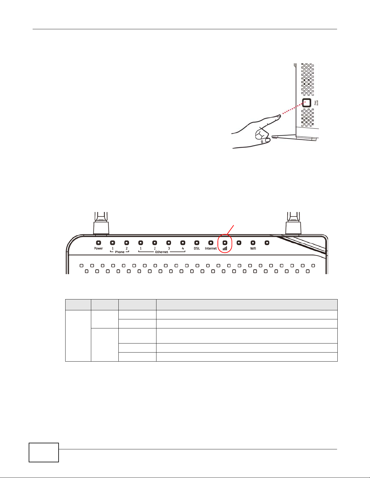
1.5 LEDs (Lights)
The following graphic displays the labels of the LEDs.
Figure 1 LEDs on the Device
None of the LEDs are on if the VDSL Router is not receiving power.
Table 1 LED Descriptions
LED COLOR STATUS DESCRIPTION
Power Green On The VDSL Router is receiving power and ready for use.
Blinking The VDSL Router is self-testing.
Red On The VDSL Router detected an error while self-testing, or there is a
device malfunction.
Off The VDSL Router is not receiving power.
Blinking Firmware upgrade is in progress.
14
Basic Home Station VDSL2 P8802T User’s Guide
Chapter 1 Introducing the VDSL Router
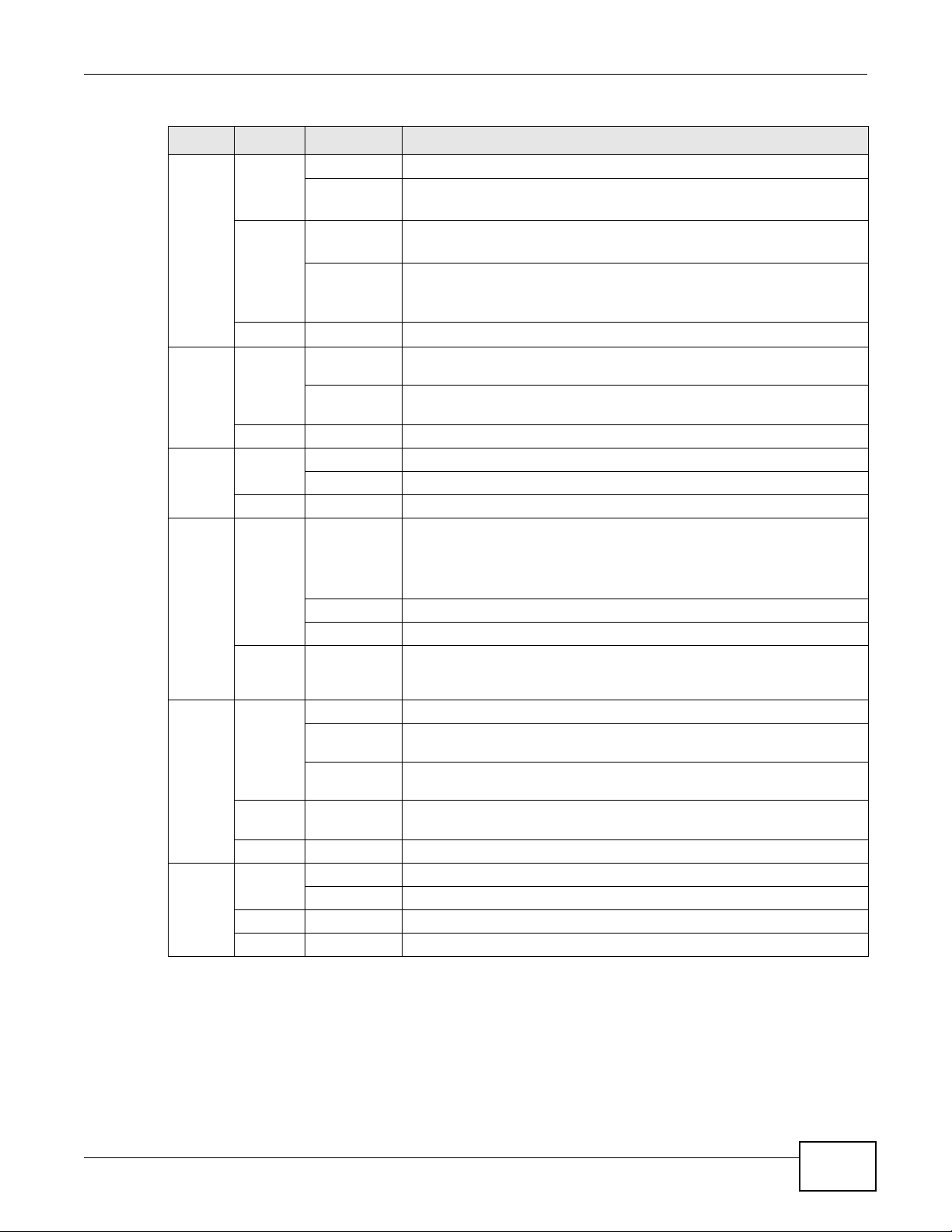
Table 1 LED Descriptions (continued)
LED COLOR STATUS DESCRIPTION
Phone
1/2
Green On A SIP account is registered for the phone port.
Blinking A telephone connected to the phone port has its receiver off of
the hook or there is an incoming call.
Orange On A SIP account is registered for the phone port and there is a
voice message in the corresponding SIP account.
Blinking A telephone connected to the phone port has its receiver off of
the hook and there is a voice message in the corresponding SIP
account.
Off The phone port does not have a SIP account registered.
Ethernet
1-4
DSL Green On The DSL line is up.
Internet Green On The VDSL Router has an IP connection but no traffic.
3G Green On The 3G backup connection through a 3G USB dongle is connected.
Wifi Green On The wireless network is activated.
Green On The VDSL Router has a successful 100 Mbps Ethernet connection with a
device on the Local Area Network (LAN).
Blinking The VDSL Router is sending or receiving data to/from the LAN at 100
Mbps.
Off The VDSL Router does not have an Ethernet connection with the LAN.
Blinking The VDSL Router is initializing the DSL line.
Off The DSL line is down.
Your device has a WAN IP address (either static or assigned by a DHCP
server), PPP negotiation was successfully completed (i f used) and the
DSL connection is up.
Blinking The VDSL Router is sending or receiving IP traffic.
Off There is no Internet connection or the gateway is in bridged mode.
Red On The VDSL Router attempted to make an IP connection but failed.
Possible causes are no response from a DHCP server, no PPPoE
response, PPPoE authentication failed.
Blinking The VDSL Router is negotiating a backup connection through a 3G
dongle or sending or receiving traffic through the backup connection.
Fast Blinking The VDSL Router is sending or receiving traffic through the backup
connection.
Red On Authentication of the 3G backup connection through a 3G USB dongle
failed.
Off The VDSL Router is using the broadband interface.
Blinking The VDSL Router is communicating with other wireless clients.
Orange Blinking The VDSL Router is setting up a WPS connection.
Off The wireless network is not activated.
Basic Home Station VDSL2 P8802T User’s Guide
15

Chapter 1 Introducing the VDSL Router
1.6 3G WAN
The USB port (at the right side of the device when you
face to the front panel) allows you to wirelessly
connect to a 3G netowk to get Internet access by
attaching a 3G dongle. You must leave the VDSL
Router DSL or Ethernet WAN port unconnected and
attached a 3G dongle to use 3G as your WAN. Y ou can
also heve the VDSL Router use the 3G WAN
connection as a backup. That means the VDSL Router
switches to the 3G wireless WAN connection after the
wired DSL or Ethernet WAN connection fails. The
VDSL Router automatically changes back to use the
wired DSL or Ethernet WAN connection when it is
available.
Figure 2 Internet Access Application: 3G WAN
1.7 The RESET Button
If you forget your password or cannot access the web configurator, you will need to use the RESET
button at the back of the device to reload the factory-default configuration file. This deletes all your
and the password will be reset to “1234”.
1 Make sure the Power LED is green and on (not blinking and not red or flashing red).
2 To set the device back to the factory default settings, press the RESET button for ten seconds or
until the Power LED begins to blink and then release it. When the Power LED begins to blink, the
defaults have been restored and the device restarts.
16
Note: The default username and password are on the label on the bottom of the Device.
Basic Home Station VDSL2 P8802T User’s Guide
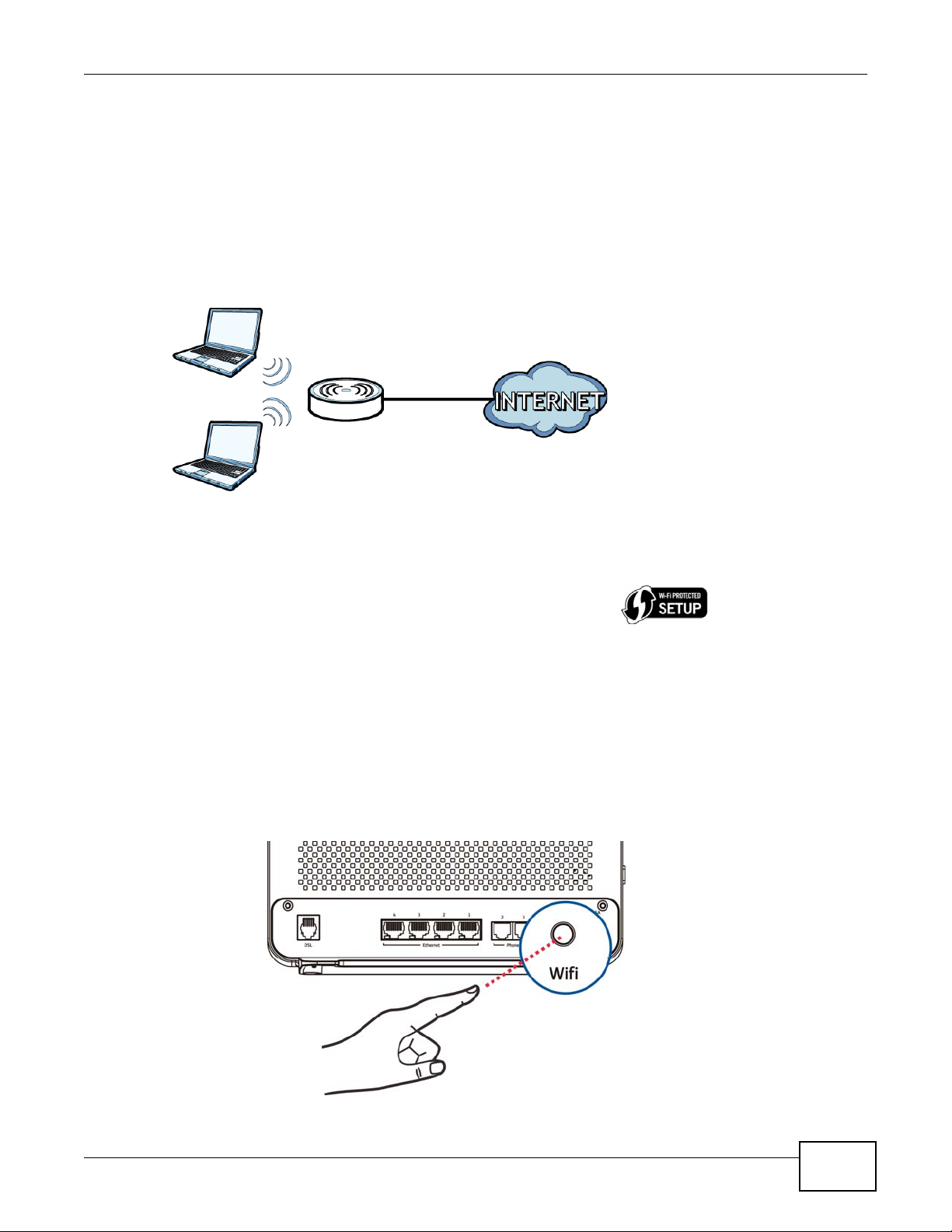
1.8 Wireless Access
The VDSL Router is a wireless Access Point (AP) for wireless clients, such as notebook computers,
smartphones, or tablets. It allows them to connect to the Internet without having to rely on
inconvenient Ethernet cables.
You can connect to y our w ireless network using the Wifi button, without having to access the Web
Configurator.
Figure 3 Wireless Access Example
Chapter 1 Introducing the VDSL Router
1.8.1 Using the Wifi Button
Note: The wireless client must be a WPS-aware device (for example, a WPS USB adapter or
PCMCIA card), which can be identified by the WPS logo
If the wireless network is turned off, press the Wifi button at the back of the VDSL Router for one
second. Once the Wifi LED turns green, the wireless network is active.
You can also use the Wifi button to quickly set up a secure wireless connection between the VDSL
Router and a WPS-compatible client by adding one device at a time.
To activate WPS:
1 Make sure the Power LED is green and not blinking.
2 Press the Wifi button for ten seconds and release it.
:
Basic Home Station VDSL2 P8802T User’s Guide
17

Chapter 1 Introducing the VDSL Router
3 Enable WPS on another WPS-enabled client device within range of the VDSL Router. If you do not
know how to enable WPS on that client device, refer to its manual. The Wifi LED flashes green and
orange while the VDSL Router sets up a WPS connection with the other WPS enabled client device.
4 Once the connection is successfully made, the Wifi LED shines green.
To turn off the wireless network, press the Wifi button on the front of the VDSL Router for one to
five seconds. The Wifi LED turns off when the wireless network is off.
18
Basic Home Station VDSL2 P8802T User’s Guide

CHAPTER 2
User Setup Guide
This chapter contains instructions to quickly set up features on the system.
• Access the VDSL Router Configuration (Section 2.1 on page 19)
• Changing the Configuration Password (Section 2.2 on page 20)
• Setting Up a 3G Backup Internet Connection (Section 2.2 on page 20)
• Setting your DSL Account’s Username and Password (Section 2.2 on page 20)
• Settup Up a Secure Wireless Network (Section 2.2 on page 20)
• Using Wireless MAC Authentication to Block a Computer’s Access to the Wireless Network
(Section 2.3 on page 28)
• Setting Up an NAT Virtual Server for a Game Server (Section 2.4 on page 29)
• Access Your Home Computer from the Internet Using DDNS (Section 2.5 on page 30)
• Configuring the Firewall (Section 2.6 on page 34)
• LAN DHCP for IP Addressing Assignment (Section 2.7 on page 36)
• Checking the Software Version (Section 2.8 on page 38)
• Restoring to Factory Default (Section 2.9 on page 39)
• How to Use File Sharing on the VDSL Router (Section 2.10 on page 40)
• Using the Media Server Feature (Section 2.11 on page 43)
• How to Share a USB Printer via Your VDSL Router (Section 2.12 on page 47)
2.1 Access the VDSL Router Configuration
1 Connect to the Web Configurator to configure the VDSL Router. Enter the LAN IP address of the
VDSL Router in your web browser (see the cover page of this guide for the default login
information).
2 The Device Info Summary screen displays. See Section 3.2 on page 61 for more information.
Basic Home Station VDSL2 P8802T User’s Guide 19
Chapter 2 User Setup Guide
2.2 Setting Up a Secure Wireless Network
Thomas sets up a wireless network to give his notebook wireless Internet access. The VDSL Router
serves as an access point (AP) to let the notebook connect to the Internet.
Thomas configures the wireless network settings on the VDSL Router and uses WPS (Section 2.2.2
on page 22) or manual configuration (Section 2.2.3 on page 26) to connect his notebook.
2.2.1 Configuring the Wireless Network Settings
This example uses the following parameters to set up a wireless network.
SSID Example
Security Level WPA2-PSK
WPA/WAPI passphrase DoNotStealMyWirelessNetwork
802.11 Mode 802.11b/g/n Mixed
20
Note: See the sticker on the bottom of the VDSL Router for the default wireless LAN
SSID, security mode, and password.
Basic Home Station VDSL2 P8802T User’s Guide
Chapter 2 User Setup Guide
1 Click Wireless to display the wireless settings. Make sure Enable Wireless is selected. Type
Example in the SSID field.
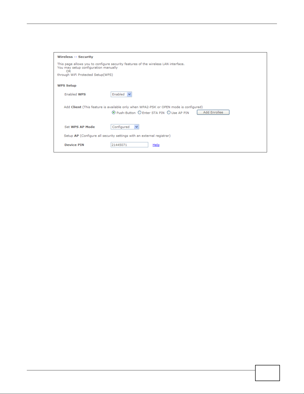
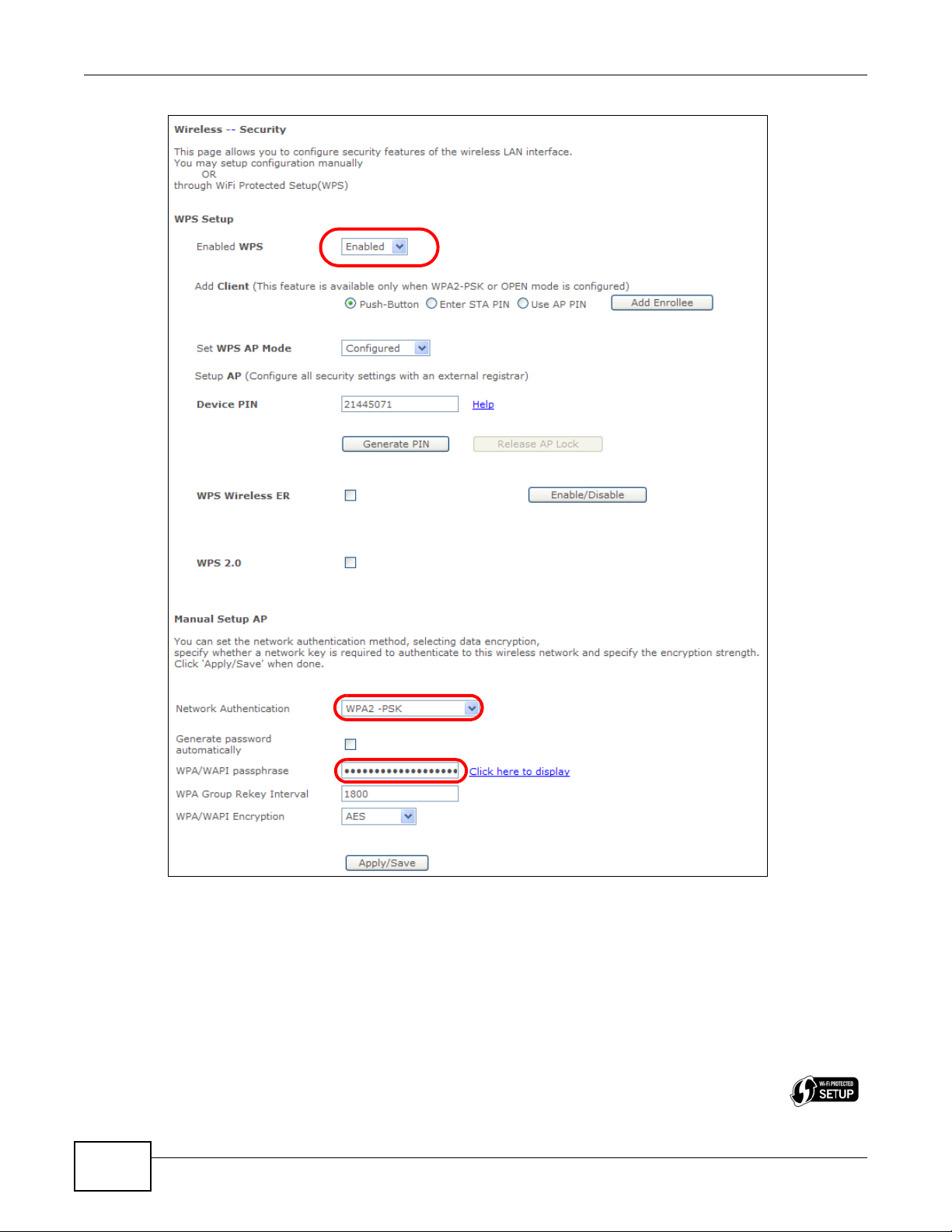
2 Click Wireless > Security, make sure Enabled WPS is set to Enabled. Select WPA2-PSK in the
Network Authentication field. Enter the WPA/WAPI passphrase. Click Apply/Save.
Basic Home Station VDSL2 P8802T User’s Guide
21
Chapter 2 User Setup Guide
Use WPS to wirelessly connect the notebook to the VDSL Router (see Section 2.2.2 on page 22) or
use the notebook’s wireless client to search for the VDSL Router (see Section 2.2.3 on page 26).
2.2.2 Using WPS
This example uses WPS to connect a ZyXEL NWD210N wireless client to the VDSL Router’s wireless
network.
Note: One way to see if the wireless client (a notebook, smartphone, tablet, wireless USB adapter,
or wireless PCMCIA card for example) supports WPS is to look for the WPS logo
22
:
Basic Home Station VDSL2 P8802T User’s Guide

Chapter 2 User Setup Guide
It covers two WPS methods to set up the wireless client settings:
• Push Button Configuration (PBC) - simply press a button. This is the easier method.
• PIN Configuration - enter a wireless client’s Personal Identification Number (PIN) in the VDSL
Router.
Push Button Configuration (PBC)
1 Make sure that your VDSL Router is on and your notebook is within range of the wireless signal.
2 Make sure that you have installed the wireless client driver and utility in your notebook.
3 In the wireless client utility, go to the WPS setting page. Enable WPS and press the Wifi button
(Start or Wifi button).
4 Push and hold the Wifi button located on the VDSL Router’s rear panel for 10 seconds.
Note: It doesn’t matter which device’s button you press first. You must press the second
button within two minutes of pressing the first one.
Note: The WPS button in the Web Confi gurator screens also has t he same function as the
one on the VDSL Router rear panel: use either.
The VDSL Router sends the wireless network settings to the wireless client. This may tak e up to two
minutes. Afterwards the wireless client can communicate with the VDSL Router securely.
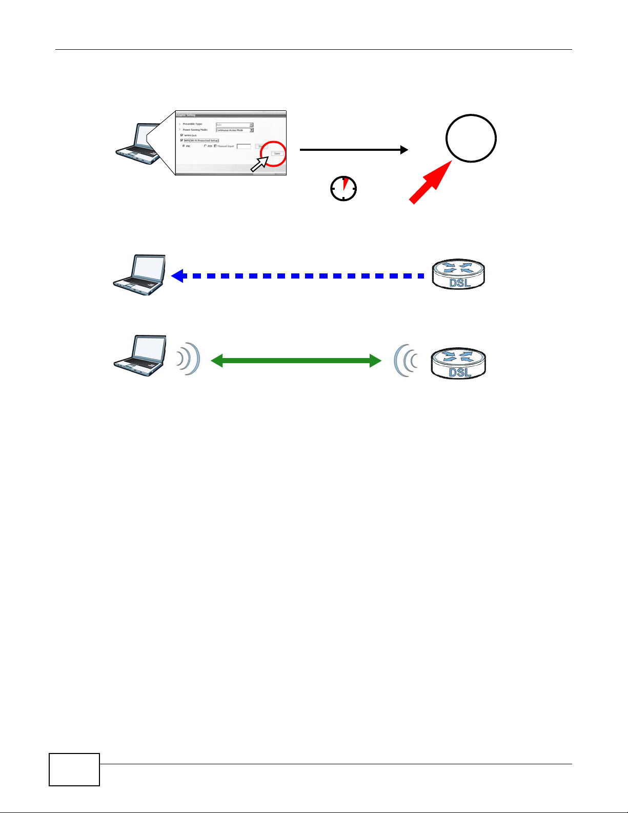
The following figure shows an example of how to set up a wireless network and its security by
pressing a button on both VDSL Router and wireless client.
Basic Home Station VDSL2 P8802T User’s Guide
23
Chapter 2 User Setup Guide
Wireless Client
VDSL Router
SECURITY INFO
COMMUNICATION
WITHIN 2 MINUTES
Press and hold for
10 seconds
Wifi
Example WPS Process: PBC Method
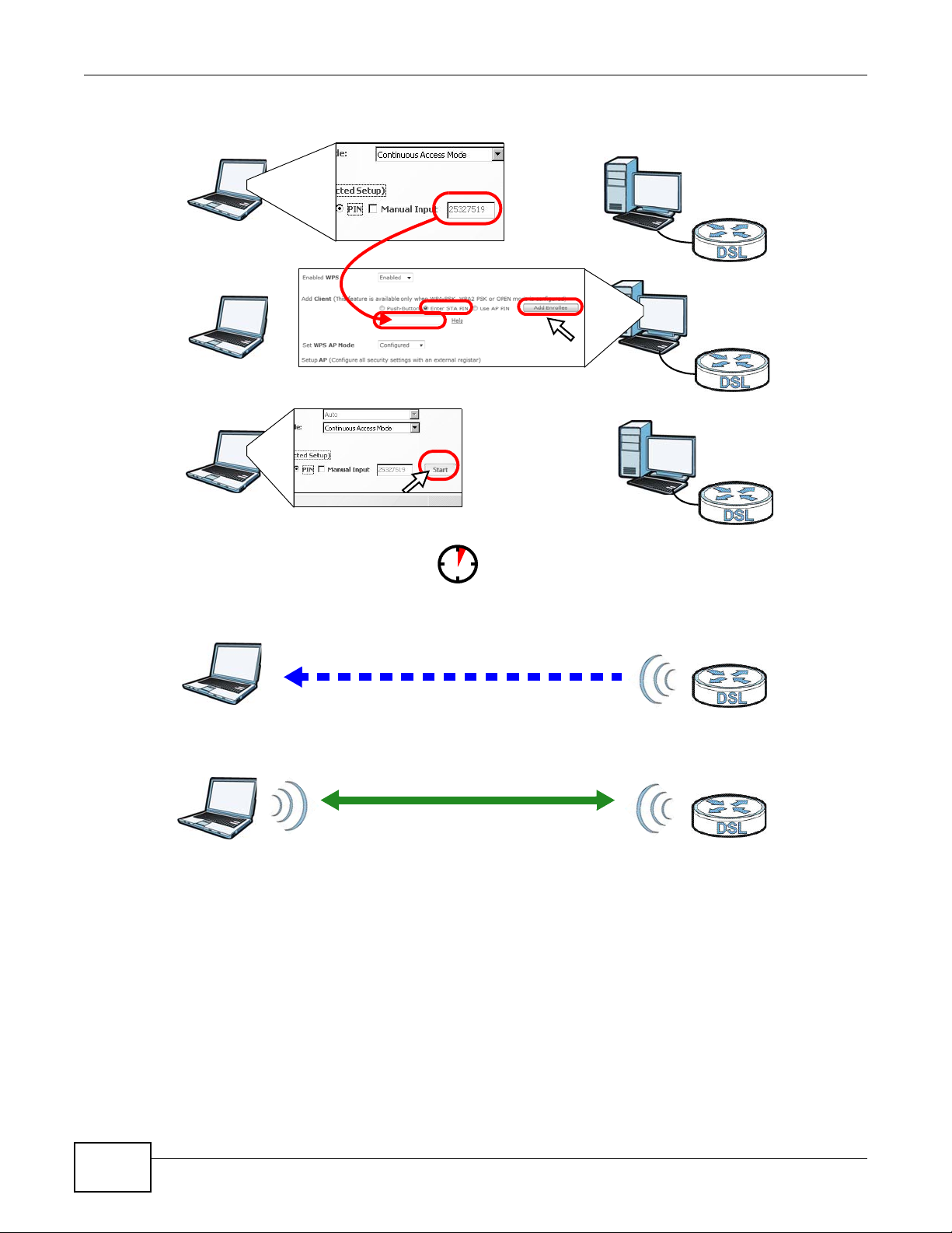
PIN Configuration
When you use the PIN configuration method, you need to use both the VDSL Router’s web
configurator and the wireless client’s utility.
1 Launch your wireless client’s configuration utility. Go to the WPS settings and select the PIN method
to get a PIN number.
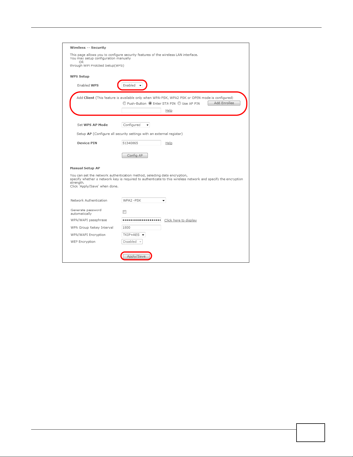
2 Log into the VDSL Router’s web configurator and click Wireless > Security. Enable the WPS
function and select Enter STA PIN. Enter the PIN number of the wireless client and click the Add
Enrollee button. Click Apply/Save.
24
Basic Home Station VDSL2 P8802T User’s Guide
Chapter 2 User Setup Guide
3 Activate WPS on the wireless client utility screen within two minutes.
The VDSL Router authenticates the wireless client and sends it the proper configuration settings.
This may take up to two minutes. The wireless client can then communicate with the VDSL Router
securely.
The following figure shows how to set up a wireless network and its security on a VDSL Router and
a wireless client by using PIN method.
Basic Home Station VDSL2 P8802T User’s Guide
25
Chapter 2 User Setup Guide
Authentication by PIN
SECURITY INFO
WITHIN 2 MINUTES
Wireless Client
VDSL Router
COMMUNICATION
Example WPS Process: PIN Method
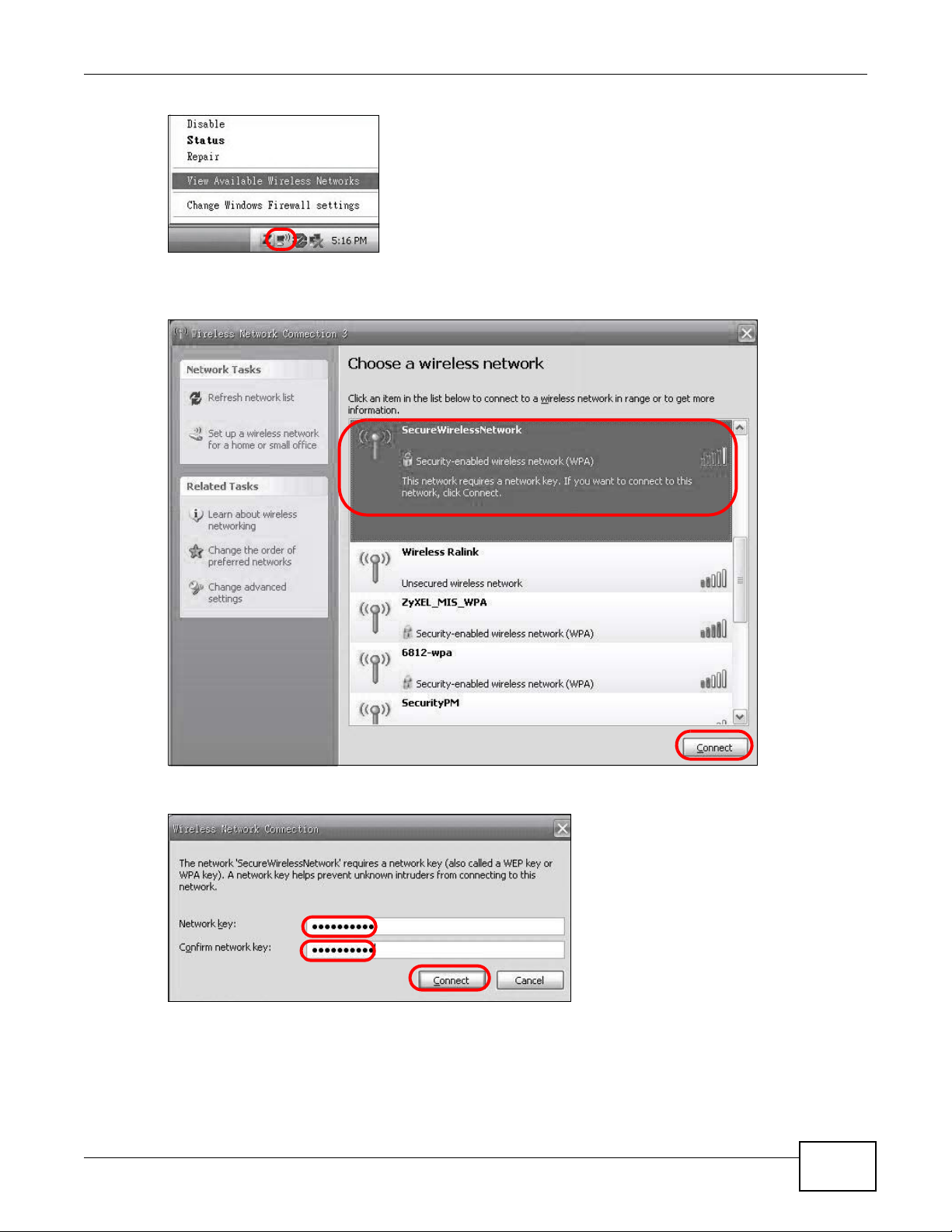
2.2.3 Without WPS
This example uses Windows XP to connect wirelessly to your VDSL Router.
1 Right-click the wireless adapter icon at the bottom right of your computer monitor. Click View
Available Wireless Networks.
26
Basic Home Station VDSL2 P8802T User’s Guide
Chapter 2 User Setup Guide
A
2 Select the VDSL Router’s SSID name (“SecureWirelessNetwork” in this example) and click
Connect (A).
3 Enter the password when prompted and click Connect.
4 You may have to wait several minutes while your computer connects to the wireless network.
5 Congratulations! Browse to your favorite websites. If you cannot, check that you connected to the
correct AP, and the signal strength is OK. Click your wireless adapter’s icon and click Enable. Some
notebooks also have a physical button that enables or disables the wireless adaptor.
Basic Home Station VDSL2 P8802T User’s Guide
27
Chapter 2 User Setup Guide
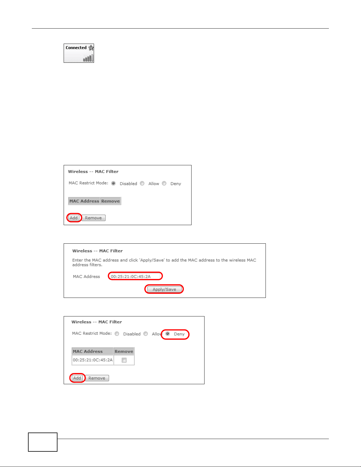
2.3 Using Wireless MAC Authentication to Block a Computer’s Access to the Wireless Network
Use MAC Authentication to block a computer from accessing the wireless network based on the
computer’s MAC address.
Note: MAC Authentication offers lim it ed security.
1 Click Wireless > MAC Filter. In the MAC Filter screen, click Add.
2 In the MAC Address field, enter the MAC address of the computer to block and click Apply/Save.
3 The MAC address appears in the MAC List. Set the MAC Restrict Mode to Deny and click Add.
28
Basic Home Station VDSL2 P8802T User’s Guide
Chapter 2 User Setup Guide
D=192.168.1.34
WAN
LAN
TCP/UDP port 6500
A
UDP ports 2302 and 13139
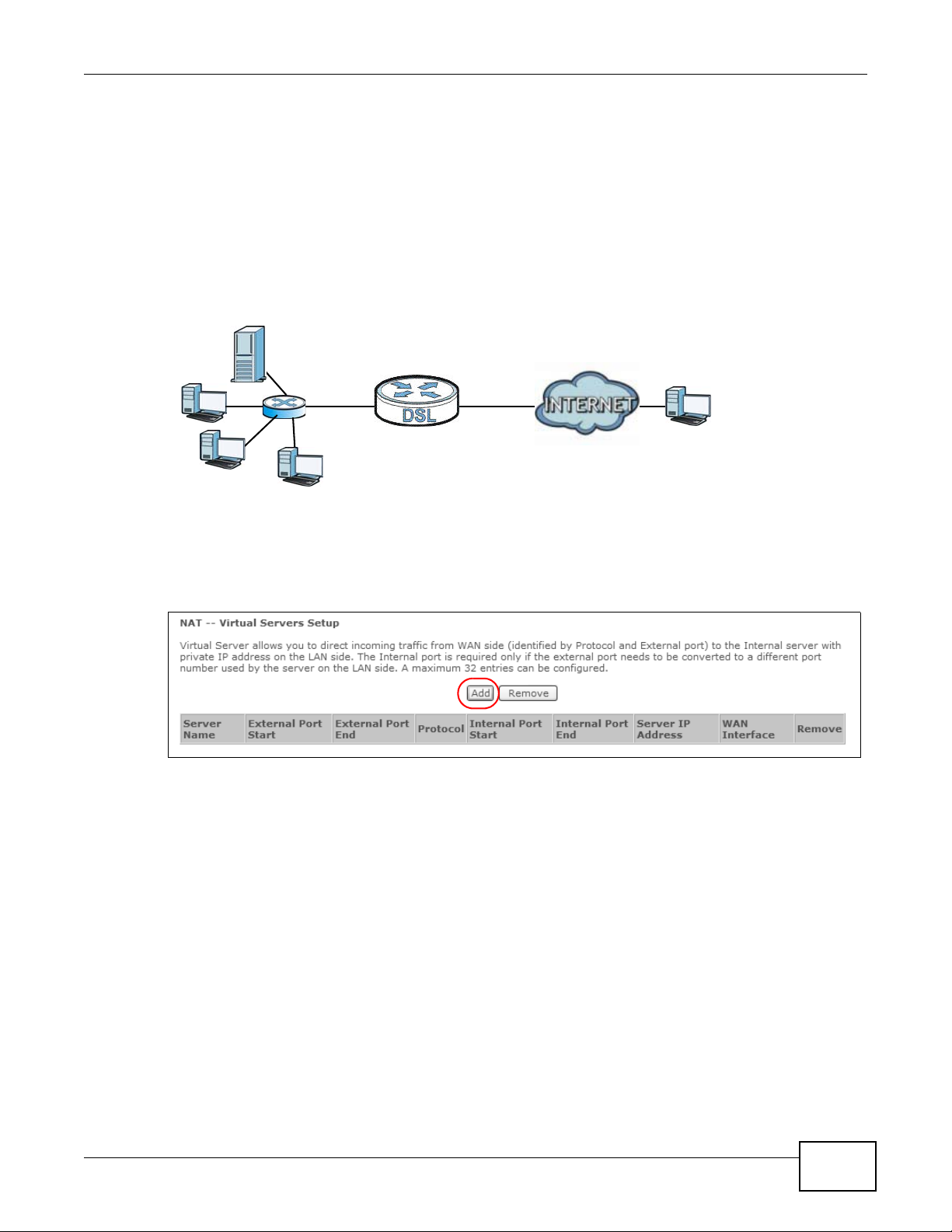
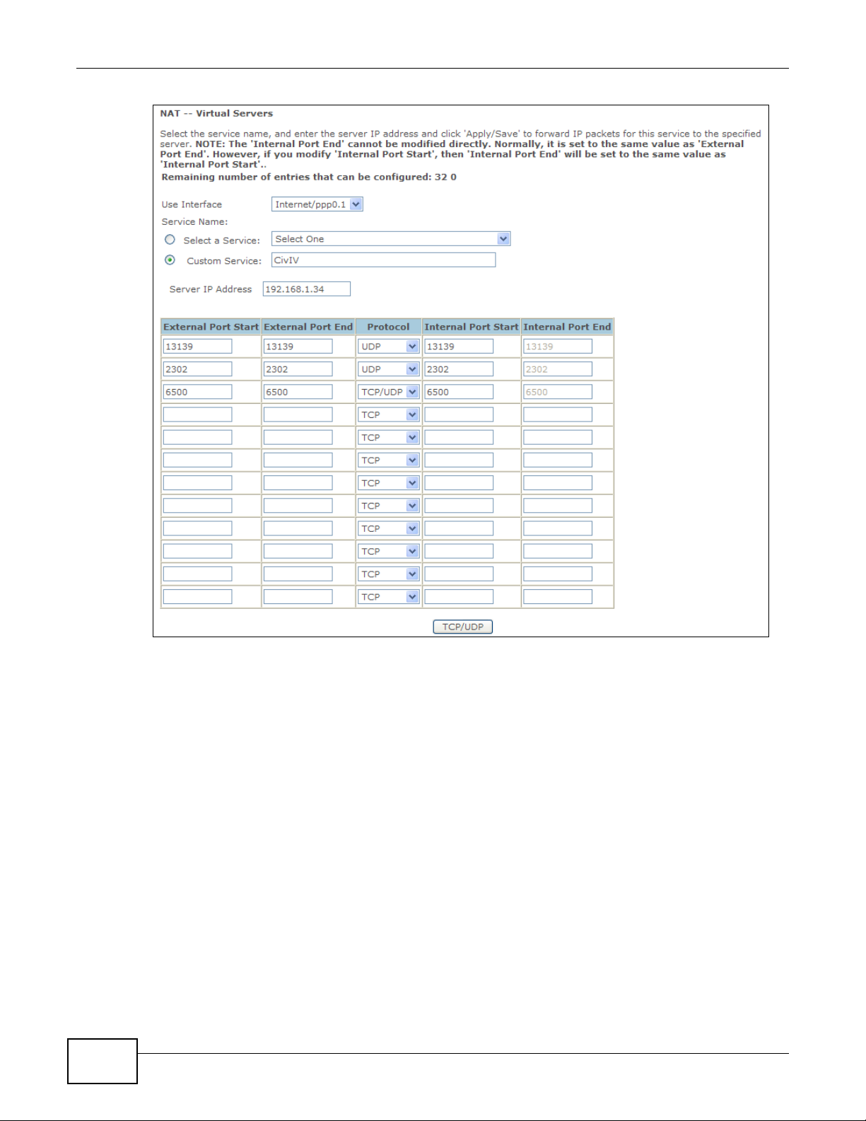
2.4 Setting Up a NAT Virtual Server for a Game Server
This examples configures a virtual server to forward traffic from Civilization IV players on the
Internet (A in the figure below) to a server on a computer behind the VDSL Router.
Note: If firewall is enabled, you may also need to configure a firewall rule for the relevant
ports. See Section 2.6.2 on page 34.
Tutorial: NAT Port Forwarding Setup
Thomas configures virtual servers to forward TCP and UDP port 6500, and UDP ports 2302 and
13139 traffic to port 6500 at the server’s IP address of 192.168.1.34.
1 Click Advanced Setup > NAT > Virtual Servers and then Add.
2 Select the incoming interface for the traffic. Specify a name (CivIV in this example) in the Custom
Service field. Set the Server IP Address to 192.168.1.34. Add UDP ports 2302 and 13139 and
port number 6500 for TCP & UDP protocols. Click TCP/UDP.
Basic Home Station VDSL2 P8802T User’s Guide
29
Chapter 2 User Setup Guide
Players on the Internet then can access Thomas’ server.
2.5 Access Your Home Computer from the Internet Using DDNS
It is inconvenient for you to access your home computer from the Internet if your VDSL Router uses
a dynamic WAN IP address since it changes dynamically. Dynamic DNS (DDNS) allows you to
access your home computer using a domain name.
Note: Enable remote desktop server service on your home computer. The remote desktop
server feature covered here is included in Windows Professional, Business, and
Ultimate versions.
Note: If firewall is enabled, you may also need to configure a firewall rule for the relevant
ports. See Section 2.6.2 on page 34.
30
Basic Home Station VDSL2 P8802T User’s Guide

To use this feature, apply for DDNS service at www.dyndns.org or TZO. This tutorial covers:
w.x.y.z
a.b.c.d
http://zyxelrouter.dyndns.org
A
• Registering a DDNS Account on www.dyndns.org
• Configuring DDNS on Your VDSL Router
• Configuring Port Forwarding on your VDSL Router
• Testing the DDNS Setting
Note: If you have a private WAN IP address, then you cannot use DDNS.
2.5.1 Registering a DDNS Account on www.dyndns.org
Chapter 2 User Setup Guide
1 Open a browser and type http://www.dyndns.org.
2 Apply for a user account. This tutorial uses UserName1 and 12345 as the username and
password.
3 Log into www.dyndns.org using your account.
4 Add a new DDNS host name. This tutorial uses the following settings as an example.
•Hostname: zyxelrouter.dyndns.org
•Service Type: Host with IP address
• IP Address: Enter the WAN IP address that your VDSL R outer is current ly using. You can find the
IP address on the VDSL Router’s Web Configurator Status page.
Then you will need to configure the same account and host name on the VDSL Router later.
2.5.2 Configuring DDNS on Your VDSL Router
Configure the following settings in the Advanced Setup > DNS > Dynamic DNS > Add screen.
•Select DynDNS.org as the D-DNS provider.
•Type zyxelrouter.dyndns.org in the Host Name field.
• Leave the interface set to the default unless you have configured another interface to use.
• Enter the user name (UserName1) and password (12345).
• Click Apply/Save.
Basic Home Station VDSL2 P8802T User’s Guide
31

Chapter 2 User Setup Guide
2.5.3 Configuring Port Forwarding on your VDSL Router
Configure the following settings in the Advanced Setup > NAT > Virtual Servers > Add screen.
• Leave the interface set to the default unless you have configured another interface to use.
•Select Custom Service and type RD in the field.
• Type the LAN IP address of your computer in the Server IP Address field. To check this on your
home computer, click Start, All Programs, Accessories and then Command Prompt. In the
Command Prompt window, type "ipconfig" and then press [ENTER]. This example uses
192.168.1.64. See Configuring Static DHCP to configure a Static DHCP rule for this IP address.
•Type 3389 in the External/Internal Start/End Port fields. This is the listening port for
Windows remote desktop.
• Select the TCP in the Protocol field.
32
Basic Home Station VDSL2 P8802T User’s Guide

Chapter 2 User Setup Guide
Click Apply/Save.
2.5.4 Testing the DDNS Setting
Test your access to your computer from the Internet.
1 Open the remote desktop client application on the remote computer (using the IP address a.b.c.d)
that is connected to the Internet.
2 Type http://zyxelrouter.dyndns.org and press [Enter].
3 Your computer’s remote desktop login page should appear.
Basic Home Station VDSL2 P8802T User’s Guide
33

Chapter 2 User Setup Guide
2.6 Configuring the Firewall
Click Advanced Setup > Firewall > General and select Active Firewall to turn on Denial of
Service (DoS) protection. Select the default policy’s Active check box to block sessions initiated
from the Internet from coming in through the ppp0.1 WAN interface. Click Apply.
Firewall Example: Edit Rule: Desti nation Address
2.6.1 Interface Default Policy
Click the Firewall > General screen’s Add button to add an interface default policy to block or
allow sessions initiated from the network connected to an interface. This example allows sessions
initiated from the Internet to come in through the ppp1.1 WAN interface.
Firewall Example: Edit Rule: Desti nation Address
2.6.2 Firewall Rules
Use Firewall > Rules to control traffic by source and destination IP address and port.
Note: You may need to configure a firewall rule for the relevant ports if you use a NAT
virtual server or DMZ host.
1 Click Add to create a new rule.
34
Basic Home Station VDSL2 P8802T User’s Guide

Firewall Example: Edit Rule: Desti nation Address
Chapter 2 User Setup Guide
2 This example allows incoming TCP or UDP port 6500 traffic from interface ppp0.1.
Basic Home Station VDSL2 P8802T User’s Guide
35

Chapter 2 User Setup Guide
Firewall Example: Edit Rule: Desti nation Address
Firewall Example: Edit Rule: Select Customized Servi ces
3 Your new rule displays in the list.
Firewall Example: Edit Rule: Desti nation Address
2.7 LAN DHCP for IP Addressing Assignment
The following example shows how to configure LAN DHCP settings.
Click Advanced Setup > LAN to display the LAN settings. Under the Enable DHCP Server option
change the DHCP server IP address range. Set Leased Time to specify how long to lease an IP
address to a LAN computer. Click Apply/Save.
36
Basic Home Station VDSL2 P8802T User’s Guide

Firewall Example: Edit Rule: Desti nation Address
Chapter 2 User Setup Guide
2.7.1 Configuring Static DHCP
Use static DHCP to have the VDSL Router always give the same IP address to a specific computer.
1 Click Advanced Setup > LAN to display the LAN settings. Under the Static IP Lease List, click
Add Entries.
Basic Home Station VDSL2 P8802T User’s Guide
37

Chapter 2 User Setup Guide
Firewall Example: Edit Rule: Desti nation Address
2 Enter the computer’s MAC address and the LAN IP address to give the computer and click Apply/
Save.
2.8 Checking the Software Version
Click . The Device Info. The screen displays the version of the software installed on the VDSL
Router.
38
Basic Home Station VDSL2 P8802T User’s Guide

Firewall Example: Edit Rule: Desti nation Address
Chapter 2 User Setup Guide
2.9 Restoring to Factory Default
This procedure restores the factory default settings to the VDSL Router.
1 Click Management > Restore Default > Restore Default Settings.
Firewall Example: Edit Rule: Desti nation Address
2 Click OK.
Firewall Example: Edit Rule: Desti nation Address
3 The restore screen displays.
Basic Home Station VDSL2 P8802T User’s Guide
39

Chapter 2 User Setup Guide
Note: The Power LED flashes and stays on green when ready to reconfigure. Follow the
instructions provided by your ISP to reprogram your modem.
Note: The VDSL Router’ s back stick er displays the default LAN IP address, us ername, and
password.
Firewall Example: Edit Rule: Desti nation Address
2.10 How to Use File Sharing on the VDSL Router
These sections cover how to use file sharing to allow LAN users to access a USB storage device
connected to the VDSL Router as if it was directly connected to their computers.
Note: Remember to control physical access to the USB drive so someone doesn’t access
files by simply connecting it to a computer.
2.10.1 Set Up File Sharing
1 Connect your USB device to the USB port at the back panel of the VDSL Router.
2 Click Advanced Setup > USB Services > File Sharing and enable file sharing. Click Add new
user to set up a new file sharing user account.
40
Basic Home Station VDSL2 P8802T User’s Guide

3 Enter a user name and password and click Apply.
Chapter 2 User Setup Guide
4 Disable the root account and click Apply/Save.
Basic Home Station VDSL2 P8802T User’s Guide
41

Chapter 2 User Setup Guide
2.10.2 Access Your Shared Files From a Computer
Note: This example uses Microsoft’s Windows 7 to browse your shared files.
1 Open Windows Explorer and in the address bar type a double backslash “\\” followed by the VDSL
Router’s LAN IP address and press [ENTER].
2 A login screen displays. Type the user name and password you set up for file sharing and click OK.
Note: Once you log into the file share via your VDSL Router, you do not have to log in
again unless you restart your computer or the VDSL Router.
3 Double-click the usbshare folder and browser its contents.
42
Basic Home Station VDSL2 P8802T User’s Guide

2.11 Using the Media Server Feature
Computer with
VDSL Router
USB Storage Device
Windows Media Player
The media server streams video, music, and photo files from a USB storage device to DLNAcompliant media clients on your network. Connect the USB storage device to the VDSL Router’s
USB port. This section gives examples of using the media server with the following media clients:
• Microsoft (MS) Windows Media Player
• ZyXEL DMA-2500, a digital media adapter - see the DMA-2500 Quick Start Guide to set up the
DMA-2500 to work with your television (TV) before using the instructions here.
2.11.1 Configuring the VDSL Router
Click Advanced Setup > USB Services > Media Server. The digital media server settings
display. Enable the digital media server and click Apply/Save.
Tutorial: USB Services > Me dia Server
Chapter 2 User Setup Guide
2.11.2 Using Windows Media Player
This section shows you how to play the media files on the USB storage device connected to your
VDSL Router using Windows Media Player.
Tutorial: Media Server Setup (Using Windows Media Player)
2.1 1.2.1 Windows Vista
1 Open Windows Media Player and click Library > Media Sharing as follows.
Basic Home Station VDSL2 P8802T User’s Guide
43

Chapter 2 User Setup Guide
Tutorial: Media Sharing using Windows Vista
2 Select Find media that others are sharing in the following screen and click OK.
Tutorial: Media Sharing using Windows Vista (2)
3 The VDSL Router displays as a playlist in the Library screen’s left panel. Click the category icons in
the right panel to display the media files in the USB storage device attached to your VDSL Router.
44
Basic Home Station VDSL2 P8802T User’s Guide

Tutorial: Media Sharing using Windows Vista (3)
P8701T
P8701T
P8701T
P8701T
2.1 1.2.2 Windows 7
Chapter 2 User Setup Guide
1 Open Windows Media Player. It automatically detects the VDSL Router. Right-click Other Libraries
> Refresh Other Libraries if the VDSL Router does not display in the left panel.
Tutorial: Media Sharing using Windows 7 (1)
2 Select a category and wait for Windows Media Player to list the files available.
Basic Home Station VDSL2 P8802T User’s Guide
45

Chapter 2 User Setup Guide
P8701T
P8701T
DMA-2500
VDSL Router
USB Storage Device
Tutorial: Media Sharing using Windows 7 (2)
2.11.3 Using a Digital Media Adapter
This section shows you how to use a ZyXEL DMA-2500 to play media files in a USB storage device
connected to the VDSL Router.
Note: Set up your DMA-2500 with the TV according to the instructions in the DMA-2500
Quick Start Guide before using this tutorial.
1 Connect the DMA-2500 to an available LAN port on your VDSL Router.
Tutorial: Media Server Setup (Using DMA)
2 Turn on the TV and wait for the DMA-2500 Home screen to appear . Using the remote control, go to
MyMedia to open the following screen. Select the VDSL Router as your media server.
46
Basic Home Station VDSL2 P8802T User’s Guide

Chapter 2 User Setup Guide
Tutorial: Media Sharing using DMA-2500
3 The screen lists available media files in the USB storage device. Select a file and push the Play
button in the remote control to open it.
Tutorial: Media Sharing using DMA-2500 (2)
2.12 How to Share a USB Printer via Your VDSL Router
Your VDSL Router can act as a print server and let the computers on your network use the USB
printer connected to the VDSL Router’s USB port.
1 Go to Advanced Setup > USB Services > to enable the print server function on the VDSL Router.
Enter the printer’s name and manufacturer and model number. Click Apply/Save to save your
settings.
Basic Home Station VDSL2 P8802T User’s Guide
47

Chapter 2 User Setup Guide
2 Connect the USB printer to the VDSL Router if you have not done so already.
3 See Section 2.12.1 on page 48 and/or Section 2.12.2 on page 52 for examples of how to set up a
printer on your computer. The computers on your network must have the printer software already
installed before they can use the printer.
Note: Y our printer’ s installation i nstructions ma y ask that you connect the printer to your
computer. Connect the printer to the VDSL Router instead.
2.12.1 Add a New Printer Using Windows
This example shows how to connect a printer behind the VDSL Router to a computer using the
Windows XP Professional. Some menu items may look different on your operating system.
1 Click Start > Control Panel > Printe rs and Faxes to open the Printers and Faxes screen. Click
Add a Printer.
48
Basic Home Station VDSL2 P8802T User’s Guide

Chapter 2 User Setup Guide
2 The Add Printer Wizard screen displays. Click Next.
3 Select A network printer, or a printer attached to another computer and click Next.
Basic Home Station VDSL2 P8802T User’s Guide
49

Chapter 2 User Setup Guide
4 Select Connect to a printer on the Internet or on a home or office network: and enter
“http://192.168.1.1:631/printers/USB_PRINTER” as the URL to access the print server (VDSL
Router). Click Next.
Note: If you change the VDSL Router’s LAN IP address, use the new IP address in the URL
to access the print server.
5 Select the make of the printer that you want to connect to the print server in the Manufacturer list
of printers.
6 Select the printer model from the list of Printers.
7 If your printer is not displayed in the list of Printers, insert the printer driver installation CD/disk or
download the driver file to your computer, click Have Disk… and install the new printer driver.
8 Click Next to continue.
50
Basic Home Station VDSL2 P8802T User’s Guide

Chapter 2 User Setup Guide
9 Select Yes to use this printer as the default printer on your computer. Otherwise select No. Click
Next to continue.
10 The following screen shows your current printer settings. Select Finish to complete adding a new
printer.
Basic Home Station VDSL2 P8802T User’s Guide
51

Chapter 2 User Setup Guide
2.12.2 Add a New Printer Using Macintosh OS X
Complete the following steps to set up a print server driver on your Macintosh computer.
2.12.2.1 Mac OS 10.3 and 10.4
This example shows how to connect a printer behind the VDSL Router to your computer using Mac
OS X v10.4.11. Some menu items may look different on your operating system.
1 Click the Finder icon on the Dock (a place holding a series of icons/shortcuts at the bottom of the
desktop) or double-click your Mac hard disk icon (Mac OS X in this example) on your desktop.
2 The Mac HD window displays. Open the Applications folder.
3 Open the Utilities folder.
52
Basic Home Station VDSL2 P8802T User’s Guide

4 Double-click the Printer Setup Utility icon.
Chapter 2 User Setup Guide
5 Click the Add icon at the top of the screen.
6 Click the IP Printer tab to set up your printer.
•Press the alt key and click More Printers in the Printer Browser screen.
•Select Advanced from the top drop-down list.
Basic Home Station VDSL2 P8802T User’s Guide
53

Chapter 2 User Setup Guide
•Select Internet Printing Protocol using HTTP from the Device drop-down list.
• Enter a descriptive name for the printer in the Device Name field.
•In the Device URL field, enter “http://192.168.1.1:631/printers/USB_PRINTER” as the
URL to access the print server (VDSL Router).
Note: If you change the VDSL Router’s LAN IP address, use the new IP address in the URL
to access the print server.
• Select your printer manufacturer from the Printer Model drop-down list and then select a
printer model. Click Add to save and close the Printer Browser configuration screen.
7 The new network printer displays in the Printer List. The default printer Name displays in bold
type.
8 Your print server driver setup is complete. You can now use the VDSL Router’s print server to print
from a Mac computer.
2.12.2.2 Mac OS 10.5 and 10.6
This example shows how to connect a printer behind the VDSL Router to your computer using Mac
OS X v10.6.2. Some menu items may look different on your operating system.
54
Basic Home Station VDSL2 P8802T User’s Guide

Chapter 2 User Setup Guide
1 Click the Finder icon on the Dock or double-click your Mac hard disk icon (Mac OS X in this
example) on your desktop to open the Mac HD window.
2 Open the Applications folder.
3 Double-click the System Preferences icon.
4 Click the Print & Fax icon.
Basic Home Station VDSL2 P8802T User’s Guide
55

Chapter 2 User Setup Guide
5 Select the Printing tab and click the + icon to add a new printer.
6 Click the Advanced button on the Add Printer toolbar to set up your printer.
If the Advanced button doesn’t appear, Ctrl-click the toolbar, select Customize Toolbar... and
then drag the Advanced button onto the toolbar.
•Select Internet Printing Protocol (HTTP) from the Type drop-down list.
•Select Another Device from the Device drop-down list.
•In the URL field, enter “http://192.168.1.1:631/printers/USB_PRINTER” as the URL to
access the print server (VDSL Router).
Note: If you change the VDSL Router’s LAN IP address, use the new IP address in the URL
to access the print server.
• Enter a descriptive name for the printer and where it is located.
56
Basic Home Station VDSL2 P8802T User’s Guide

• Select your printer manufacturer from the Print Using drop-down list and then select a
printer model. Click Add to save and close the Printer Browser configuration screen.
7 The new network printer displays in the Printers list.
Chapter 2 User Setup Guide
8 Your print server driver setup is complete. You can now use the VDSL Router’s print server to print
from a Mac computer.
Basic Home Station VDSL2 P8802T User’s Guide
57

Chapter 2 User Setup Guide
58
Basic Home Station VDSL2 P8802T User’s Guide

PART II
Technical Reference
59

60

CHAPTER 3
Device Info Screens
3.1 Overview
Use the Device Info screens to look at the current status of the Device, system resources,
interfaces (LAN, WAN, and WLAN), and SIP account registration status.
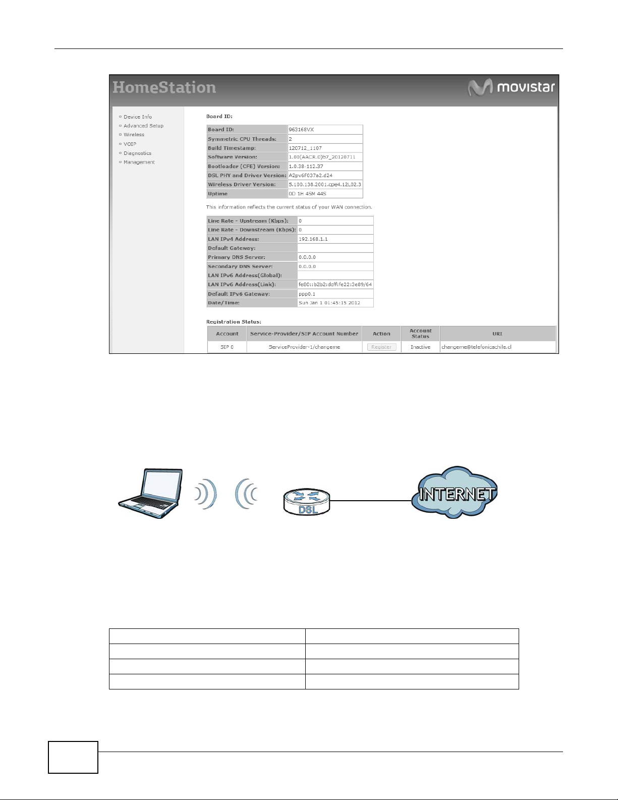
3.2 The Device Info Summary Screen
Log into the VDSL Router’s web configurator or click Device Info >Summary to view a summary
screen of information about the VDSL Router.
Figure 4 Device Info Summary Screen
Basic Home Station VDSL2 P8802T User’s Guide 61

Chapter 3 Device Info Screens
Each field is described in the following table.
Table 2 Device Info Summary Screen
LABEL DESCRIPTION
Board ID This field displays the ID number of the circuit board in the VDSL Router.
Symmetric CPU
Threads
Build
Timestamp
Software
Version
Bootloader
(CFE) Version
DSL PHY and
Driver Version
Wireless Driver
Version
Uptime This field displays how long the VDSL Router has been running since it last started up.
Line Rate -
Upstream
Line Rate -
Downstream
LAN IPv4
Address
Default
Gateway
Primary DNS
Server
Secondary DNS
Server
LAN IPv6
Address
(Global)
LAN IPv6
Address (Link)
Default IPv6
Gateway
Date/Time This field displays the VDSL Router’s current day of the week, month, hour, minute, second,
Registratio n Status
Account
ServiceProvider/SIP
Account
Number
This field displays the number of threads in the VDSL Router’s CPU.
This field displays the date (YYMMDD) and time (HHMM) of the firmware in the VDSL Router.
This field displays the current version of the firmware inside the VDSL Router.
This field displays the version of bootloader the VDSL Router is using.
This field displays the version of the modem code the VDSL Router is using.
This field displays the version of the driver for the VDSL Router’s wireless chipset.
This field displays the WAN port’s sending traffic speed.
This field displays the WAN port’s receiving traffic speed.
This field displays the current IP address of the VDSL Router in the LAN.
This field displays the IP address of the gateway through which the VDSL Router sends
traffic unless it matches a static route.
The VDSL Router tries this DNS server first when it needs to resolve a domain name into a
numeric IP address.
The VDSL Router uses this DNS server first when it needs to resolve a domain name into a
numeric IP address if the primary DNS server does not respond.
This field displays the current global IPv6 address of the VDSL Router.
This field displays the current IPv6 address of the VDSL Router in the LAN.
This field displays the IPv6 address of the gateway through which the VDSL Router sends
IPv6 traffic unless it matches a static route.
and year.
This column displays each SIP account in the VDSL Router.
This column displays the service provider name and SIP number for each SIP
account.
62
Basic Home Station VDSL2 P8802T User’s Guide

Table 2 Device Info Summary Screen (continued)
LABEL DESCRIPTION
Action
Account Status
If the SIP account is already registered with the SIP server, the Account Status
field displays Registered.
• Click Unregister to delete the SIP account’s registration in the SIP server. This
does not cancel your SIP account, but it deletes the mapping between your SIP
identity and your IP address or domain name.
If the SIP account is not registered with the SIP server, the Account Status field
displays Not Registered.
• Click Register to have the VDSL Router attempt to register the SIP account
with the SIP server.
The button is grayed out if the SIP account is disabled.
This field displays the current registration status of the SIP account. You have to
register SIP accounts with a SIP server to use VoIP.
Inactive - The SIP account is not active. You can activate it in VoIP > SIP > SIP
Account.
Not Registered - The last time the VDSL Router tried to register the SIP account
with the SIP server, the attempt failed. Use the Register button to register the
account again. The VDSL Router automatically tries to register the SIP account
when you turn on the VDSL Router or when you activate it.
Chapter 3 Device Info Screens
Registered - The SIP account is already registered with the SIP server. You can
use it to make a VoIP call.
URI
This field displays the account number and service domain of the SIP account. You
can change these in the VoIP > SIP screens.
3.3 The WAN Info Screen
Log into the VDSL Router’s web configurator and click Device Info > WAN to view a summary
screen of information about the VDSL Router’s WAN connections.
Figure 5 WAN Info Screen
Basic Home Station VDSL2 P8802T User’s Guide
63

Chapter 3 Device Info Screens
Each field is described in the following table.
Table 3 WAN Info Screen
LABEL DESCRIPTION
Interface This shows the name of the interface used by this connection.
Description This is the service name of this connection.
Type This shows the method of encapsulation used by t his connection.
VlanMuxID This indicates the VLAN ID number assigned to traffic sent through this connection. This
IPv6 This displays whether or not IPv6 is enabled on the interface.
Igmp This shows whether IGMP (Internet Group Multicast Protocol) is activated or not for this
MLD This shows whether Multicast Listener Discovery (MLD) is activated or not for this
NAT This shows whether NAT is activated or not for this interface. NAT is not available when the
Status This displays the connection state or Unconfigured if the interface has not yet been
IPv4 Address This displays the interface’s current IPv4 address if it has one. Click connect to initiate the
IPv6 Address This displays the interface’s current IPv6 address if it has one. Click connect to initiate the
A default name ipoa*, pppoa*, atm* or ptm* indicates DSL port. The ppp* indicates a
PPP connection via any one of the WAN interface.
The number after the dot (.) represents the VLAN ID number assigned to traffic sent
through this connection. The number after the underscore (_) represents the index number
of connections through the same interface.
(null) means the entry is not valid.
0 and 35 or 0 and 1 are the default VPI and VCI numbers. The last number represents the
index number of connections over the same PVC or the VLAN ID number assigned to traffic
sent through this connection.
(null) means the entry is not valid.
displays N/A when there is no VLAN ID number assigned.
connection. IGMP is not available when the connection uses the bridging service.
connection. MLD is not available when the connection uses the bridging service.
connection uses the bridging service.
configured.
WAN interface’s connection.
WAN interface’s connection.
3.4 The 3G Status Screen
Log into the VDSL Router’s web configurator and click Device Info > 3G to view a summary screen
of information about the VDSL Router’s 3G connection.
64
Basic Home Station VDSL2 P8802T User’s Guide

Chapter 3 Device Info Screens
Figure 6 3G Status Screen
Each field is described in the following table.
Table 4 3G Status Screen
LABEL DESCRIPTION
Status • NoDevice when no 3G card is inserted,
• Disabled when the 3G WAN is not activated,
• Up when the 3G connection is up,
• Down when the 3G c o nnection is down,
• NoResponse when there is no response from the inserted 3G card,
• InvalidPIN if the PIN code you entered in the WAN > 3G Backup screen is not the
right one for the 3G card you inserted,
• NeedPUK if you enter the PIN (Personal Identification Number) code incorrectly for
three times and the SIM card is blocked by your ISP,
• DialFail when the VDSL Router fails to dial up a 3G connection.
•or InvalidSIM when the SIM card is damaged or not inserted.
If a link displays in this field, click the link to view more status information or enter the
correct PIN or PUK (Personal Unblocking Key) code.
Service
Provider
Signal Strength This displays the 3G connection’s signal quality.
Connection
Uptime
3G Card
Manufacturer
3G Card Model This displays the model name of the 3G USB dongle.
3G Card F/W
Version
3G Card IMEI IMEI (International Mobile Equipment Identity) is a 15-digit code in decimal format that
SIM Card IMSI IMSI (International Mobile Subscriber Identity) is a 15-digit code that identifies the SIM
This displays the name of your 3G network service provider.
This displays how long the 3G connection has been connected since it last came up.
This displays the name of the company that produced the 3G USB dongle.
This displays the software version of the 3G USB dongle.
identifies the 3G device.
card.
3.5 The LAN Statistics Screen
Log into the VDSL Router’s web configurator and click Device Info > Statistics > LAN to view a
summary screen of information about the VDSL Router’s LAN connections.
Basic Home Station VDSL2 P8802T User’s Guide
65

Chapter 3 Device Info Screens
Figure 7 LAN Statistics Screen
Each field is described in the following table.
Table 5 LAN Statistics Screen
LABEL DESCRIPTION
Interface These fields identify the LAN interfaces. eth0 ~ eth3 represen t th e ethernet LAN ports 1 ~
Received /
Transmitted
Received
Bytes This indicates the number of bytes received on this interface.
Pkts This indicates the number of packets received on this interface.
Errs This indicates the number of frames with errors received on this interface.
Drops This indicates the number of received packets dropped on this interface.
Transmitted
Bytes This indicates the number of bytes transmitted on this interface.
Pkts This indicates the number of transmitted packets on this interface.
Errs This indicates the number of frames with errors transmitted on this interface.
Drops This indicates the number of outgoing packets dropped on this interface.
Reset Statistics Click this to clear the screen’s statistics counters.
4. wlo represents the wireless LAN interface.
These fields display the number of bytes, packets, error packets, and dropped packets for
each interface.
3.6 The WAN Statistics Screen
Log into the VDSL Router’s web configurator and click Device Info > Statistics > WAN Service
to view a summary screen of information about the VDSL Router’s WAN connections.
66
Basic Home Station VDSL2 P8802T User’s Guide

Chapter 3 Device Info Screens
Figure 8 WAN Statistics Screen
Each field is described in the following table.
Table 6 WAN Statistics Screen
LABEL DESCRIPTION
Interface This shows the name of the WAN interface used by this connection.
The default name ipoa*, pppoa*, atm* or ptm* indicates the DSL port. ppp* indicates a
PPP connection via any one of the WAN interfaces. ppp3G0 indicates a PPP connection
through the 3G interface.
The number after the dot (.) represents the VLAN ID number assigned to traffic sent
through this connection. The number after the underscore (_) represents the index number
of connections through the same interface.
(null) means the entry is not valid.
Description This shows the descriptive name of this connec tion.
ATM interfaces include the VPI and VCI. 0 and 35 or 0 and 1 are the default VPI and VCI
numbers. The last number represents the index n umber of connections over the same PVC
or the VLAN ID number assigned to traffic sent through this connection.
(null) means the entry is not valid.
Received
Bytes This indicates the number of bytes received on this interface.
Pkts This indicates the number of packets received on this interface.
Errs This indicates the number of frames with errors received on this interface.
Drops This indicates the number of received packets dropped on this interface.
Transmitted
Bytes This indicates the number of bytes transmitted on this interface.
Pkts This indicates the number of transmitted packets on this interface.
Errs This indicates the number of frames with errors transmitted on this interface.
Drops This indicates the number of outgoing packets dropped on this interface.
Reset Statistics Click this to clear the screen’s statistics counters.
3.7 The xTM Statistics Screen
Log into the VDSL Router’s web configurator and click Device Info > Statistics > xTM to display
ATM or PTM connection information.
Basic Home Station VDSL2 P8802T User’s Guide
67

Chapter 3 Device Info Screens
Figure 9 xTM Statistics Screen
Each field is described in the following table.
Table 7 xTM Statistics Screen
LABEL DESCRIPTION
Port Number This identifies the ATM or PTM port.
In Octets This displays the number of 8-bit binary digits (bytes) received through the port.
Out Octets This displays the number of 8-bit binary digits (bytes) sent through the port.
In Packets This displays the number of packets received through the port.
Out Packets This displays the number of packets sent through the port.
In OAM Cells This displays the number of OAM (Operational, Administration and Maintenance) cells
Out OAM Cells This displays the number of OAM cells sent through the port.
In ASM Cells This displays the number of ASM (Autonomous Status Message) cells received through the
Out ASM Cells This displays the number of ASM cells sent through the port.
In Packet Errors This displays the number of errored packets received on the port.
In Cell Errors This displays the number of errored cells received on the port.
Reset Click this to clear the screen’s statistics counters.
received through the port.
port.
3.8 The xDSL Statistics Screen
Log into the VDSL Router’s web configurator and click Device Info > Statistics > xDSL to display
information about the VDSL Router’s VDSL or ADSL connections.
68
Basic Home Station VDSL2 P8802T User’s Guide

Figure 10 xDSL Statistics Screen
Chapter 3 Device Info Screens
Each field is described in the following table.
Table 8 xDSL Statistics Screen
LABEL DESCRIPTION
Mode This field identifies the DSL mode of the DSL connection.
Traffic Type This displays the type of traffic the DSL port is sending and receiving.
Status This displays the current state of setting up the DSL connection.
Link Power
State
Downs tream These ar e the statistics for the traffic direction coming into the port from the service
This displays the DSL connec tion’s current power usage or powe r saving mode. null display s
when there is no DSL connection.
provider.
Basic Home Station VDSL2 P8802T User’s Guide
69

Chapter 3 Device Info Screens
Table 8 xDSL Statistics Screen (continued)
LABEL DESCRIPTION
Upstream These are the statistics for the traffic direction going out from the port to the service
Line Coding
(Trellis)
SNR Margin
(0.1 dB)
Attenuation
(0.1 dB)
Output Power
(0.1 dBm)
Attainable Rate
(Kbps):
Rate (Kbps) This displays the data transfer rates at which the port is receiving and sending.
Super Frames This displays the number of ADSL superframes the DSL connection received and
Super Frame
Errors
RS Words This displays the number of Reed Solomon error correction words for received and
RS Correctable
Errors
RS
Uncorrectable
Errors
HEC Errors Header Error Control (HEC) checks for errors in packet headers.
OCD Errors The number of Out of Cell Delineation errors for received and transmitted traffic. An OCD
LCD Errors The number of Loss of Cell Delineation errors for received and transmitted traffic. An LCD
Total Cells This displays the total number of DSL cells including headers.
Data Cells This displays the number of data payload DSL cells, excluding headers.
Bit Errors This displays the number of errored bits.
Total ES This displays the number of Errored Seconds meaning the number of seconds containing at
Total SES This displays the nu mber of Severely Errored Seconds meaning the number of seconds
Total UAS This displays the number of UnAvailable Seconds.
xDSL BER Test Click this to open a screen where you can perform a ADSL Bit Error Rate (BER) test to
Reset Statistics Click this to clear the screen’s statistics counters.
provider.
This displays whether or not the port is using Trellis coding for traffic. T relli s coding helps to
reduce the noise in ADSL transmissions. Trellis may reduce throughput but it makes the
connection more stable.
This displays the Signal-to-Noise Ratio margin (in 0.1 dB). A DMT sub-carrier’s SNR is the
ratio between the received signal power and the received noise power. The signal-to-noise
ratio margin is the maximum that the received noise power could increase with the system
still being able to meet its transmission targets.
This displays the line attenuation, measured in tenths of a decibe l (0.1 dB). This attenuation
is the difference between the power transmitted at the near-end and the power received at
the far-end. Attenuation is affected by the channel characteristics (wire gauge, quality,
condition and length of the physical line).
This displays the far end actual aggregate transmit power (in dBm). Downstream is how
much port the service provider is using to transmit to the port. Upstream is how much
power the port is using to transmit to the service provider.
These are the highest theoretically possible transfer rates at which the port could send and
receive data.
transmitted. Each superframe contains 68 ADSL data f rames and a one-frame synch symbol
for a total number of 69 frames.
This displays the number of errored ADSL superframes the DSL connection received and
transmitted.
transmitted traffic.
This displays the number of errored packets corrected by Reed Solomon error correction for
received and transmitted traffic.
This displays the number of errored packets that Reed Solomon error correction could not
correct for received and transmitted traffic.
error means seven consecutive ATM cells had Header Error Control (HEC) violations.
state means an OCD condition persisted for 4 milliseconds.
least one errored block or at least one defect.
containing 30% or more errored blocks or at least one defect. This is a subset of ES.
determine the quality of the ADSL connection.
70
Basic Home Station VDSL2 P8802T User’s Guide

3.8.1 The ADSL BER Test Screen
Do the following while the VDSL Router has an ADSL connection to perform a ADSL Bit Error Rate
(BER) test to determine the quality of the ADSL connection.
1 Log into the VDSL Router’s web configurator and click Device Info > Statistics > xDSL > xDSL
BER Test to display this screen. Select a test duration and click Start.
2 Click Stop to finish the test.
Chapter 3 Device Info Screens
3 The test results display including the test’s duration, the number of bits transferred, the n umber of
errored bits, and the ratio of errored bits to transmitted bits.
3.9 The Route Info Screen
Log into the VDSL Router’s web configurator and click Device Info > Route to display the VDSL
Router’s routing table.
Basic Home Station VDSL2 P8802T User’s Guide
71

Chapter 3 Device Info Screens
Figure 11 Route Info Screen
Each field is described in the following table.
Table 9 Route Info Screen
LABEL DESCRIPTION
Destination This displays the IP address to which this entry applies.
Gateway This displays the gateway the VDSL Router uses to send traffic to the entry’s destination
Subnet Mask This displays the subnet mask of the destination net.
Flag This displays whether the route is up (U), the VDSL Router drops packets for this
Metric The metric represents the “cost” of transmission for routing purposes. IP routing uses hop
Service The name of a specific service to which the route applies if one is specified.
Interface The interface through which this route sends traffic.
address.
destination (!), the route uses a gateway (G), the target is a host (H), reinstate route for
dynamic routing (R), the route was dynamically installed by redirect (D), or modified from
redirect (M).
count as the measurement of cost, with a minimum of 1 for directly-connected networks.
3.10 The ARP Info Screen
Log into the VDSL Router’s web configurator and click Device Info > ARP to display Address
Resolution Protocol information. This screen lists the IP addresses the VDSL Router has mapped to
MAC addresses.
Figure 12 ARP Info Screen
Each field is described in the following table.
Table 10 ARP Info Screen
LABEL DESCRIPTION
IP address The learned IP address of a device connected to one of the system’s ports.
Flags Static - static entry, Dynamic - dynamic entry that is not yet complete, Complete -
dynamic entry that is complete.
HW Address The MAC address of the device with the listed IP address.
Device The interface through which the VDSL Router sends traffic to the device listed in the entry.
72
Basic Home Station VDSL2 P8802T User’s Guide

3.11 The DHCP Leases Screen
Log into the VDSL Router’s web configurator and click Device Info > DHCP to display the VDSL
Router’s list of IP address currently leased to DHCP clients.
Figure 13 DHCP Leases Screen
Each field is described in the following table.
Table 11 DHCP Leases Screen
LABEL DESCRIPTION
Hostname This field displays the name used to identify this device on the network (the computer
name). The VDSL Router learns these from the DHCP client requests. “None” shows here for
a static DHCP entry.
MAC Address This field displays the MAC address to which the IP address is currently assigned or for
which the IP address is reserved. Click the column’ s heading ce ll to sort t he table entri es by
MAC address. Click the heading cell again to reverse the sort order.
IP Address This field displays the IP address currently assigned to a DHCP client or reserved for a
specific MAC address. Click the column’s heading cell to sort th e table entries by IP address.
Click the heading cell again to reverse the sort order.
Expires In This field displays how much longer the IP address is leased to the DHCP client.
Chapter 3 Device Info Screens
Basic Home Station VDSL2 P8802T User’s Guide
73

Chapter 3 Device Info Screens
74
Basic Home Station VDSL2 P8802T User’s Guide

4.1 Overview
WAN
This chapter discusses the VDSL Router’s WAN screens. Use these screens to configure your VDSL
Router for Internet access.
A WAN (Wide Area Network) connection is an outside connection to another network or the
Internet. It connects your private networks, such as a LAN (Local Area Network) and other
networks, so that a computer in one location can communicate with computers in other locations.
Figure 14 LAN and WAN
CHAPTER 4
WAN
3G (third generation) standards for the sending and receiving of voice, video, and data in a mobile
environment.
You can attach a 3G wireless adapter to the USB port and set the VDSL Router to use this 3G
connection as your WAN or a backup when the wired WAN connection fails.
Figure 15 3G WAN Connection
4.1.1 What You Can Do in this Chapter
•Use the Layer 2 Interface screens to view, remove or add layer-2 WAN interfaces (Section 4.2
on page 78 and Section 4.3 on page 81).
Basic Home Station VDSL2 P8802T User’s Guide 75

Chapter 4 WAN
•Use the WAN Service screens to view, remove or add a WAN interface. You can also configure
•Use the 3G Backup screen to configure 3G WAN connection (Section 4.5 on page 97).
Table 12 WAN Setup Overview
the WAN settings on the VDSL Router for Internet access (Section 4.4 on page 83).
LAYER-2 INTERFACE INTERNET CONNECTION
CONNECTION
ADSL/VDSL
over PTM
ADSL over ATM EoA Routing PPPoE/PPP0A ATM PCV configuration, PPP
DSL LINK
TYPE
N/A Routing PPPoE PPP information, IPv4/IPv6 IP
4.1.2 What You Need to Know
The following terms and concepts may help as you read this chapter.
Encapsulation Method
MODE ENCAPSULATION CONNECTION SETTINGS
address, routing feature, DNS
server, VLAN, QoS, and MTU
IPoE IPv4/IPv6 IP address, routing
feature, DNS server, VLAN, QoS,
and MTU
Bridge N/A VLAN and QoS
information, IPv4/IPv6 IP address,
routing feature, DNS server, VLAN,
QoS, and MTU
IPoE/IPoA ATM PCV configuration, IPv4/IPv6
IP address, routing feature, DNS
server, VLAN, QoS, and MTU
Bridge N/A ATM PCV configuration, and QoS
Encapsulation is used to include data from an upper layer protocol into a lower layer protocol. To set
up a WAN connection to the Internet, you need to use the same encapsulation method used by your
ISP (Internet Service Provider). If your ISP offers a dial-up Internet connection using PPPoE (PPP
over Ethernet), they should also provide a username and password (and service name) for user
authentication.
WAN IP Address
The WAN IP address is an IP address for the VDSL Router, which makes it accessible from an
outside network. It is used by the VDSL Router to communicate with other devices in other
networks. It can be static (fixed) or dynamically assigned by the ISP each time the VDSL Router
tries to access the Internet.
If your ISP assigns you a static WAN IP address, they should also assign you the subnet mask and
DNS server IP address(es).
ATM
Asynchronous Transfer Mode (ATM) is a WAN networking technology that provides high-speed data
transfer. ATM uses fixed-size packets of information called cells. With ATM, a high QoS (Quality of
76
Basic Home Station VDSL2 P8802T User’s Guide

Chapter 4 WAN
Service) can be guaranteed. ATM uses a connection-oriented model and establishes a virtual circuit
(VC) between Finding Out More
PTM
Packet Transfer Mode (PTM) is packet-oriented and supported by the VDSL2 standard. In PTM,
packets are encapsulated directly in the High-level Data Link Control (HDLC) frames. It is designed
to provide a low-overhead, transparent way of transporting packets over DSL links, as an
alternative to ATM.
3G
3G (Third Generation) is a digital, packet-switched wireless technology. Bandwidth usage is
optimized as multiple users share the same channel and bandwidth is only allocated to users when
they send data. It allows fast transfer of voice and non-voice data and provides broadband Internet
access to mobile devices.
IPv6 Introduction
IPv6 (Internet Protocol version 6), is designed to enhance IP address size and features. The
increase in IPv6 address size to 128 bits (from the 32-bit IPv4 address) allows up to 3.4 x 10
addresses. The VDSL Router can use IPv4/IPv6 dual stack to connect to IPv4 and IPv6 networks,
and supports IPv6 rapid deployment (6RD).
38
IP
IPv6 Addressing
The 128-bit IPv6 address is written as eight 16-bit hexadecimal blocks separated by colons (:). This
is an example IPv6 address 2001:0db8:1a2b:0015:0000:0000:1a2f:0000.
IPv6 addresses can be abbreviated in two ways:
• Leading zeros in a block can be omitted. So 2001:0db8:1a2b:0015:0000:0000:1a2f:0000 can
be written as 2001:db8:1a2b:15:0:0:1a2f:0.
• Any number of consecutive blocks of zeros can be replaced by a double colon. A double colon can
only appear once in an IPv6 address. So 2001:0db8:0000:0000:1a2f:0000:0000:0015 can be
written as 2001:0db8::1a2f:0000:0000:0015, 2001:0db8:0000:0000:1a2f::0015,
2001:db8::1a2f:0:0:15 or 2001:db8:0:0:1a2f::15.
IPv6 Prefix and Prefix Length
Similar to an IPv4 subnet mask, IPv6 uses an address prefix to represent the network address. An
IPv6 prefix length specifies how many most significant bits (start from the left) in the address
compose the network address. The prefix length is written as “/x” where x is a number. For
example,
2001:db8:1a2b:15::1a2f:0/32
means that the first 32 bits (2001:db8) is the subnet prefix.
Basic Home Station VDSL2 P8802T User’s Guide
77

Chapter 4 WAN
IPv6 Subnet Masking
Both an IPv6 address and IPv6 subnet mask compose of 128-bit binary digits, which are divided
into eight 16-bit blocks and written in hexadecimal notation. Hexadecimal uses four bits for each
character (1 ~ 10, A ~ F). Each block’s 16 bits are then represented by four hexadecimal
characters. For example, FFFF:FFFF:FFFF:FFFF:FC00:0000:0000:0000.
4.1.3 Before You Begin
You need to know your Internet access settings such as encapsulation and W AN IP address. Get this
information from your ISP.
4.2 The Layer-2 Interface ATM Screen
The VDSL Router must have a layer-2 interface to allow users to use the DSL port to access the
Internet. The screen varies depending on the interface type you select. Log into the VDSL Router’s
web configurator and click Advanced Setup > Layer2 Interface > ATM Interface to manage
the ATM layer-2 interfaces.
Note: The ATM and PTM layer-2 interfaces cannot work at the same time.
Figure 16 Layer-2 Interface: ATM
The following table describes the fields in this screen.
Table 13 Layer-2 Interface: ATM
LABEL DESCRIPTION
Interface The name of a configured layer-2 interface.
Vpi This displays the Virtual Path Identifier (VPI).
Vci This displays the Virtual Channel Identifier (VCI).
DSL Latency This displays whether the ATM interface uses interleave delay (Path1) or fast mode with
Category This displays the ATM traffic class.
Peak Cell Rate This displays the maximum rate at which the sender can send cells.
Sustainable Cell
Rate
Max Burst Size
Link Type This is the DSL link type of the ATM layer-2 interface.
Conn Mode This shows the connection mode of the layer-2 interface.
no interleave delay (Path0).
This displays the average cell rate (long-term) at which the sender can send cells.
This displays the maximum number of cells that can be sent at the peak rate.
78
Basic Home Station VDSL2 P8802T User’s Guide

Table 13 Layer-2 Interface: ATM (continued)
LABEL DESCRIPTION
IP QoS This displays whether QoS (Quality of Service) is enabled on the interface.
MPAAL
Prec/Alg/Wght
Remove Select an interface and click the Remove button to delete it. You cannot remove a layer-
Add Click this button to create a new ATM layer-2 interface.
This displays the interface’s default queue precedence, queuing algorithm, and weighted
round robin weight.
2 interface when a WAN service is associated with it.
4.2.1 Layer-2 ATM Interface Configuration
Click the Add button in the Layer2 Interface: ATM screen to open the following screen. Use this
screen to create a new layer-2 interface. You can have multiple ATM layer-2 interfaces using
different VPI and/or VCI values. The screen varies depending on the interface type you select.
Figure 17 DSL ATM Interface Configuration
Chapter 4 WAN
Basic Home Station VDSL2 P8802T User’s Guide
79

Chapter 4 WAN
The following table describes the fields in this screen.
Table 14 Layer-2 ATM Interface Configuration
LABEL DESCRIPTION
ATM PVC
Configuration
VPI The valid range for the VPI is 0 to 255. Enter the VPI assigned to you.
VCI The valid range for the VCI is 32 to 65535 (0 to 31 is reserved for local managem ent of
Select DSL Latency Select Path0 (Fast) to use no interleaving and have faster transmission (a “fast
Select DSL Link
Type
Encapsulation
Mode
Service Category Select UBR Without PCR or UBR With PCR for applications that are non-time
VPI (Virtual Path Identifier) and VCI (Virtual Channel Identifier) define a virtual circuit.
This section is available only when you configure an ATM layer-2 interface.
ATM traffic). Enter the VCI assigned to you.
channel”). Suitable only for a good line with little need for error correction.
At the time of writing the VDSL Router supports fast mode only and interleaved is
reserved for future use.
Select EoA (Ethernet over ATM) to have an Ethernet header in the packet, so that you
can have multiple services/connections over one PVC. You can set each connection to
have its own MAC address or all connections share one MAC address but use different
VLAN IDs for different services. EoA supports ENET ENCAP (IPoE), PPPoE and RFC1483/
2684 bridging encapsulation methods.
Select PPPoA (PPP over ATM) to allow just one PPPoA connection over a PVC.
Select IPoA (IP over ATM) to allow just one RFC 1483 routing connection over a PVC.
Select the ISP’s method of multiplexing.
• VC/MUX: In VC multiplexing, each protocol is carried on a separate ATM virtual
circuit (VC). To transport multiple protocols, the VDSL Router needs separate VCs.
There is a binding between a VC and the type of the network protocol carried on the
VC. This reduces payload overhead since there is no need to carry protocol
information in each Protocol Data Unit (PDU) payload.
• LLC/SNAP-BRIDGING: In LCC encapsulation, bridged PDUs are encapsulated by
identifying the type of the bridged media in the SNAP header. This is available only
when you select EoA in the Select DSL Link Type field.
• LLC/ENCAPSULATION: More than one protocol can be carried over the same VC.
This is available only when you select PPPoA in the Select DSL Link Type field.
• LLC/SNAP-ROUTING: In LCC encapsulation, bridged PDUs are encapsulated by
identifying the type of the bridged media in the SNAP header. This is available only
when you select EoA in the Select DSL Link Type field.
sensitive, such as e-mail.
80
Select CBR (Continuous Bit Rate) to specify fixed (always-on) bandwidth for voice or
data traffic.
Select Non Realtime VBR (non real-time Variable Bit Rate) for c onnectio ns that do not
require closely controlled delay and delay variation.
Select Realtime VBR (real-time Variable Bit Rate) for applications with bursty
connections that require closely controlled delay and delay variation.
Peak Cell Rate Divide the DSL line rate (bps) by 424 (the size of an ATM cell) to find the Peak Cell Rate
(PCR). This is the maximum rate at which the se n d er c an send cells. Type the PCR here.
This field is not available when you select UBR Without PCR.
Sustainable Cell
Rate
Maximum Burst
Size
The Sustain Cell Rate (SCR) sets the average cell rate (long-term) that can be
transmitted. Type the SCR, which must be less than the PCR. Note that system default is
0 cells/sec.
This field is available only when you select Non Realtime VBR or Realtime VBR.
Maximum Burst Size (MBS) refers to the maximum number of cells that can be sent at
the peak rate. Type the MBS, which is less than 65535.
This field is available only when you select Non Realtime VBR or Realtime VBR.
Basic Home Station VDSL2 P8802T User’s Guide

Chapter 4 WAN
Table 14 Layer-2 ATM Interface Configuration (continued)
LABEL DESCRIPTION
Scheduler Select the schedu le r to use for queues that have the same precedence as the default
queue. Queuing applies only when a port has more traffic than it can handle.
Weighted Round Robin scheduling services queues of the same priority level on a
rotating basis based on their queue weight. The higher a queue’s weight, the more
service it gets. This queuing mechanism divides any available bandwidth across the
different traffic queues and returns to queues that have not yet emptied.
Weighted Fair Queuing guarantees each queue's minimum bandwidth based on its
queue weight during traffic congestion. This queuing mechanism divides any available
bandwidth across the different traffic queues. Weighted fair queuing handles packets of
various sizes better than weighted round robin queuing does.
Default Queue
Weight
Default Queue
Precedence
VC WRR Weight Specify the VC’s weight for weighted round robin queuing. The higher the weight, the
VC Precedence Specify the VC’s priority for weighted round robin queuing. The smaller the number the
Back Click this button to return to the previous screen without saving any changes.
Apply/Save Click this button to save your changes and go back to the previous screen.
Specify the VC’s weight for weighed fair queuing. The higher the weight, the bigger
portion of the bandwidth the VC gets.
Specify the VC’s priority for weighed fair queuing. The smaller the number the higher
the priority.
bigger portion of the bandwidth the VC gets.
higher the priority.
4.3 The Layer-2 Interface PTM Screen
The VDSL Router must have a layer-2 interface to allow users to use the DSL port to access the
Internet. The screen varies depending on the interface type you select. Log into the VDSL Router’s
web configurator and click Advanced Setup > Layer2 Interface > PTM Interface to manage
the PTM layer-2 interfaces.
Note: The ATM and PTM layer-2 interfaces cannot work at the same time.
Figure 18 Layer-2 Interface: PTM
Basic Home Station VDSL2 P8802T User’s Guide
81

Chapter 4 WAN
The following table describes the fields in this screen.
Table 15 Layer-2 Interface: PTM
LABEL DESCRIPTION
Interface The name of a configured layer-2 interface.
DSL Latency This displays whether the A TM interfac e uses inte rleave dela y (Path1) or fast mode with
PTM Priority This does not apply at the time of writing.
Conn Mode This shows the connection mode of the layer-2 interface.
IP QoS This displays whether QoS (Quality of Service) is enabled on the interface.
Remove Select an interface and click the Remove button to delete it. You cannot remove a layer-
Add Click this button to create a new ATM layer-2 interface.
no interleave delay (Path0).
2 interface when a WAN service is associated with it.
4.3.1 Layer-2 PTM Interface Configuration
Click the Add button in the Layer2 Interface: PTM screen to open the following screen. Use this
screen to create a new layer-2 interface.
Figure 19 DSL PTM Interface Configuration
82
Basic Home Station VDSL2 P8802T User’s Guide

Chapter 4 WAN
The following table describes the fields in this screen.
Table 16 Layer-2 PTM Interface Configuration
LABEL DESCRIPTION
Select DSL Latency Select Path0 (Fast) to use no interleaving and have faster transmission (a “fast
Scheduler Select the schedu le r to use for queues that have the same precedence as the default
Default Queue
Weight
Default Queue
Precedence
Default Queue
Shaping Rate
Default Queue
Shaping Burst Size
Back Click this button to return to the previous screen without saving any changes.
Apply/Save Click this button to save your changes and go back to the previous screen.
channel”). Suitable only for a good line with little need for error correction.
At the time of writing the VDSL Router supports fast mode only and interleaved is
reserved for future use.
queue.
Weighted Round Robin scheduling services queues of the same priority level on a
rotating basis based on their queue weight. The higher a queue’s weight, the more
service it gets. This queuing mechanism divides any available bandwidth across the
different traffic queues and returns to queues that have not yet emptied.
During traffic congestion Weighted Fair Queuing guarantees each queue's minimum
bandwidth based on its default queue weight. This queuing mechanism divides any
available bandwidth across the different traffic queues. Weighted fair queuing applies
only when a port has more traffic than it can handle.
Specify the PTM interface’s weight for weighed fair queuing. The higher the weight, the
bigger portion of the bandwidth the PTM interface gets.
Specify the PTM interface’s priority for weighed fair queuing. The smaller the number
the higher the priority.
Specify the maximum transmission rate allowed for traffic on this queue.
Specify the maximum number of cells that can be sent at the default queue shaping
rate.
4.4 The WAN Service Screen
Use this screen to change your VDSL Router’s WAN settings. Click Advanced Setup > WAN
Service. The summary table shows you the configured WAN services (connections) on the VDSL
Router.
To use NAT, firewall or IGMP proxy in the VDSL Router, you need to configure a WAN connection
with PPPoE or IPoE.
Note: When a layer-2 interface is in VLAN MUX Mode, you can configure up to five WAN
services on the VDSL Router.
Basic Home Station VDSL2 P8802T User’s Guide
83

Chapter 4 WAN
Figure 20 WAN Service
The following table describes the labels in this screen.
Table 17 WAN Service
LABEL DESCRIPTION
Interface This shows the name of the interface used by this connection.
A default name ipoa*, pppoa*, atm* or ptm* indicates the DSL port. ppp* indicates a PPP
connection through any one of the WAN interfaces.
The number after the dot (.) represents the VLAN ID number assigned to traffic sent through
this connection. The number after the underscore (_) represents the index number of
connections through the same interface.
(null) means the entry is not valid.
Description This is the service name of this connection.
0 and 35 or 0 and 1 are the default VPI and VCI numbers. The last number represents the
index number of connections over the same PVC or the VLAN ID number assigned to traffic
sent through this connection.
(null) means the entry is not valid.
Type This shows the method of encapsulation used by this connection.
Vlan8021p This indicates the 802.1P priority level assigned to traffic sent through this connection. This
displays N/A when there is no priority level assigned.
VlanMuxId This indicates the VLAN ID number assigned to traffic sent through this connection. This
displays N/A when there is no VLAN ID number assigned.
ConnId This shows the index number of each connection. This displays N/A when the interface used
by the connection is in Default Mode.
Igmp This shows whether IGMP (Internet Group Multicast Protocol) is activated or not for this
connection. IGMP is not available when the connection uses the bridging service.
NAT This shows whether NAT is activated or not for this interface. NAT is not available when the
connection uses the bridging service.
IPv6 This shows whether IPv6 is activated or not for this connection. IPv6 is not available when the
connection uses the bridging service.
Mld This shows whether Multicast Listener Discovery (MLD) is activated or not for this connection.
MLD is not available when the connection uses the bridging service.
Remove Select an interface and click the Remove button to delete it. You cannot remove a layer-2
interface when a WAN service is associated with it.
Modify Click the Edit icon to configure the WAN connection.
Click the Remove icon to delete the WAN connection.
Add Click Add to create a new connection.
84
Basic Home Station VDSL2 P8802T User’s Guide

4.4.1 WAN Connection Configuration
Click the Edit or Add button in the WAN Service screen to configure a WAN connection.
4.4.1.1 WAN Interface
This screen displays when you add a new WAN connection.
Figure 21 WAN Configuration: WAN Interface
Chapter 4 WAN
The following table describes the labels in this screen.
Table 18 WAN Configuration: WAN Interface
LABEL DESCRIPTION
Select a layer 2
interface for this
service
Back Click this button to return to the previous screen.
Next Click this button to continue.
4.4.1.2 Service Type
If you set the DSL link type to PPPoA or IPoA for the ATM interface and configure a WAN
connection using the ATM interface, you only need to configure the Enter Service Description
field in this screen.
Select ptmx to use the DSL port as the WAN port and use the VDSL
technology for data transmission.
Select atmx or ipoax (where x starts from 0 and is the index number of ATM
layer-2 interfaces using different VPI and/or VCI values ) to use the DSL port as
the WAN port and use the ADSL technology for data transmission.
Basic Home Station VDSL2 P8802T User’s Guide
85

Chapter 4 WAN
Figure 22 WAN Configuration: Service Type
Figure 23 The following table describes the labels in this screen.
Table 19 WAN Configuration: Service Type
LABEL DESCRIPTION
Select WAN
service type
Enter Service
Description
Rate Limit Enter the maximum transmission r ate in Kbps for tr affic sent through the WAN connection.
Tag VLAN ID for
egress packets
Enter 802.1P
Priority
Enter 802.1Q
VLAN ID
Select the method of encapsulation used by your ISP.
Choices are PPP over Ethernet (PPPoE), IP over Ethernet and Bridging.
Specify a name for this connection or use the automatically generated one.
Otherwise, leave this field blank to disable the rate limit.
This field is not available for an A TM connection if QoS is disabled in the DSL ATM Interface
Configuration.
Select this option to add the VLAN tag ( specified below) to the outgoing tr affic through t his
connection.
This field is available when the layer-2 interface is in VLANMUX mode.
IEEE 802.1p defines up to 8 separate traffic types by inserting a tag into a MAC-layer
frame that contains bits to define class of service.
Type the IEEE 802.1p priority level (from 0 to 7) to add to traffic through this connection.
The greater the number, the higher the priority level.
This field is available when the layer-2 interface is in VLANMUX mode.
Type the VLAN ID number (from 1 to 4094) for traffic through this connection.
This field is available when the PTM interface is in VLANMUX mode.
86
Basic Home Station VDSL2 P8802T User’s Guide

Table 19 WAN Configuration: Service Type
LABEL DESCRIPTION
Network Protocol
Selection
Back Click this button to return to the previous screen.
Next Click this button to continue.
Select IPv4 Only to have the VDSL Router use only IPv4.
Select IPv4&IPv6(Dual Stack) to let the VDSL Router connect to IPv4 and IPv6
networks an choose the protocol for applications according to the address type. This lets
the VDSL Router use an IPv6 address when sending traffic through this connection. You
can only select this for a WAN service that uses the PPPoE or IPoE encapsulation method
over the ATM or PTM interface.
4.4.1.3 WAN IP Address and DNS Server
The screen differs by the encapsulation you selected in the previous screen. See Section 4.6 on
page 99 for more information.
PPPoE or PPPoA
This screen displays when you select PPP over Ethernet (PPPoE) in the WAN Service
Configuration screen or set the DSL link type to PPPoA for the ATM interface and configure a
WAN connection using the ATM interface.
Chapter 4 WAN
Basic Home Station VDSL2 P8802T User’s Guide
87

Chapter 4 WAN
Figure 24 WAN Configuration : PPPoE
88
The following table describes the labels in this screen.
Table 20 WAN Configuration: PPPoE or PPPoA
LABEL DESCRIPTION
PPP Username Enter the user name exactly as your ISP assigned. If assigned a name in the form
PPP Password Enter the password associated with the user name above.
PPPoE Service
Name
user@domain where domain identifies a service name, then enter both components
exactly as given.
Type the name of your PPPoE service here.
This field is not available for a PPPoA connection.
Basic Home Station VDSL2 P8802T User’s Guide

Chapter 4 WAN
Table 20 WAN Configuration: PPPoE or PPPoA
LABEL DESCRIPTION
Authentication
Method
Enable NAT Select this check box to activate NAT on this connection.
Enable Fullcone NAT This field is available only when you select Enable NAT. Select this check box to
Dial on Demand Select this check box to not keep the connection up all the time. Specify an idle time-
Inactivity
Timeout
PPP IP extension Sele ct this only if your service provider requires it. PPP IP extension extends the service
The VDSL Router supports PAP (Password Auth entication Protocol) and CHAP (Challenge
Handshake Authentication Protocol). CHAP is more secure than PAP; however, PAP is
readily available on more platforms.
Use the drop-down list box to select an authentication protocol for outgoing calls.
Options are:
AUTO - Your VDSL Router accepts either CHAP or PAP when requested by this remote
node.
PAP - Your VDSL Router accepts PAP only.
CHAP - Your VDSL Router accepts CHAP only.
MSCHAP - Your VDSL Router accepts MSCHAP only. MS-CHAP is the Microsoft version
of the CHAP.
activate full cone NAT on this connection.
out in the Inactivity Timeout field.
Specify an idle time-out when you select Dial on Demand. The default setting is 0,
which means the Internet session will not timeout.
provider’s IP subnet to a single LAN computer.
• It lets only one computer on the LAN connect to the WAN.
• The public IP address from the ISP is forwarded through DHCP to the LAN computer
instead of being used on the WAN PPP interface.
• It disables NAT and the firewall.
• DHCP tells the LAN computer to use the gateway as the default gateway and DNS
server.
• The VDSL Router bridges IP packets between the WAN and LAN ports except
packets destined for the VDSL Router’s LAN IP address.
Use Static IPv4
Address
IPv4 Address Enter the IPv4 address assigned by your ISP.
Use Static IPv6
Address
IPv6 Address Enter the IPv6 address assigned by your ISP.
Enable IPv6
Unnumbered Model
Launch Dhcp6c for
Address
Assignment
Enable PPP Debug
Mode
Select this option if you have a fixed IPv4 address assigned by your ISP.
Select this option if you have a fixed IPv6 address assigned by your ISP.
Select this to enable IPv6 processing on the interface without assigning an explicit IPv6
address to the interface.
Select this check box to obtain an IPv6 address from a DHCPv6 server.
The IP address assigned by a DHCPv6 server has priority over the IP address
automatically generated by the VDSL Router using the IPv6 prefix from an RA.
Select this option to display PPP debugging messages on the console.
Basic Home Station VDSL2 P8802T User’s Guide
89

Chapter 4 WAN
Table 20 WAN Configuration: PPPoE or PPPoA
LABEL DESCRIPTION
Bridge PPPoE
Frames Between
WAN and Local
Ports
Enable IGMP
Multicast Proxy
Enable MLD
Multicast Proxy
Back Click this button to return to the previous screen.
Next Click this button to continue.
Select this option to forward PPPoE packets from the WAN port to the LAN ports and
from the LAN ports to the WAN port.
In addition to the VDSL Router's built-in PPPoE client, you can select this to allow up to
ten hosts on the LAN to use PPPoE client software on their computers to connect to the
ISP via the VDSL Router. Each host can have a separate account and a public WAN IP
address.
This is an alternative to NAT for application where NAT is not appropriate.
Clear this if you do not need to allow hosts on the LAN to use PPPoE client software on
their computers to connect to the ISP.
This field is not available for a PPPoA connection.
Select this check box to have the VDSL Router act as an IGMP proxy on this connection.
This allows the VDSL Router to get subscribing information and maintain a joined
member list for each multicast group. It can reduce multicast traffic significantly.
Select Enable to have the VDSL Router act as an MLD proxy on this connection. This
allows the VDSL Router to get subscription information and maintain a joined member
list for each multicast group. It can reduce multicast traffic significantly.
IPoE
This screen displays when you select IP over Ethernet in the WAN Service Configuration
screen.
90
Basic Home Station VDSL2 P8802T User’s Guide

Figure 25 WAN Configuration : I PoE
Chapter 4 WAN
The following table describes the labels in this screen.
Table 21 WAN Configuration: IPoE
LABEL DESCRIPTION
Obtain an IP
address
automatically
Option 60 Vendor IDDHCP Option 60 identifies the vendor and functionality of the VDSL Router in DHCP
Option 61 IAID DHCP Option 61 identifies the VDSL Router in DHCP requests the VDSL Router sends to
Option 61 DUID Enter the DHCP Unique Identifier (DUID) of the VDSL Router.
A static IP address is a fixed IP that your ISP gives you. A dynamic IP address is not
fixed; the ISP assigns you a different one each time you connect to the Internet. Select
this if you have a dynamic IP address.
requests that the VDSL Ro uter sends to a DHCP serv er when get ting a WAN IP address.
Enter the Vendor Class Identifier (Option 60), such as the type of the hardware or
firmware.
a DHCP server when getting a W AN IP address. Enter th e Identi ty Assoc iation Iden tifier
(IAID) of the VDSL Router. For example, the WAN connection index number.
Basic Home Station VDSL2 P8802T User’s Guide
91

Chapter 4 WAN
Table 21 WAN Configuration: IPoE
LABEL DESCRIPTION
Option 125 Enable this to add vendor specific information to DHCP requests that the VDSL Router
sends to a DHCP server when getting a WAN IP address.
Use the following
Static IP address
WAN IP Address Enter the static IP address provided by your ISP.
WAN S ubnet
Mask
WAN gateway IP
Address
Obtain an IPv6
address
automatically
Dhcpv6 Address
Assignment
Use the following
Static IPv6 address
WAN I Pv6
Address/Prefix
Length
WAN I Pv6
Subnet Prefix
Length
WAN Next-Hop
IPv6 Address
Back Click this button to return to the previous screen.
Next Click this button to continue.
Select this if you have a static IP address.
Enter the subnet mask provided by your ISP.
Enter the gateway IP address provided by your ISP.
Select this option to have the VDSL Router use the IPv6 prefix from the connected
router’s Router Advertisement (RA) to generate an IPv6 address.
Select this check box to obtain an IPv6 address from a DHCPv6 server.
The IP address assigned by a DHCPv6 server has priority over the IP address
automatically generated by the VDSL Router using the IPv6 prefix from an RA.
Select this option if you have a fixed IPv6 address assigned by your ISP.
Enter the static IPv6 address and bit number of the IPv6 subnet mask provided by your
ISP.
Enter the bit number of the IPv6 subnet mask provided by your ISP.
Enter the gateway IPv6 address provided by your ISP.
IPoA
This screen displays only when you set the DSL link type to IPoA for the ATM interface and
configure a WAN connection using the ATM interface.
Figure 26 WAN Configuration : I PoA
The following table describes the labels in this screen.
Table 22 WAN Configuration: IPoA
LABEL DESCRIPTION
WAN IP Address Enter the static IP address provided by your ISP.
WAN Subnet Mask Enter the subnet mask provided by your ISP.
92
Basic Home Station VDSL2 P8802T User’s Guide

Table 22 WAN Configuration: IPoA
LABEL DESCRIPTION
Back Click this button to return to the previous screen.
Next Click this button to continue.
4.4.1.4 NAT, IGMP Multicast and Firewall Activation
The screen is available only when you select IP over Ethernet in the WAN Service
Configuration screen or set the DSL link type to IPoA for the ATM interface and configure a WAN
connection using the ATM interface.
Figure 27 WAN Configuration: NAT, IGMP Multicast and Firewall Activation: IPoE/IPoA
Chapter 4 WAN
The following table describes the labels in this screen.
Table 23 WAN Configuration: NAT, IGMP Multicast and Firewall Activation: IPoE
LABEL DESCRIPTION
Enable NAT Select this check box to activate NAT on this connection.
Enable Fullcone NAT Select this check box to activate full cone NAT on this connection.
Enable IGMP
Multicast Proxy
Enable MLD
Multicast Proxy
Back Click this button to return to the previous screen.
Next Click this button to continue.
4.4.1.5 Default Gateway
The screen is not available when you select Bridging in the WAN Service Configuration screen.
This field is available only when you select Enable NAT.
Select this check box to have the VDSL Router act as an IGMP proxy on this
connection. This allows the VDSL Router to get subscribing information and
maintain a joined member list for each multicast group. It can reduce multicast
traffic significantly.
Select Enable to have the VDSL Router act as an MLD proxy on this
connection. This allows the VDSL Router to get subscription information and
maintain a joined member list for each multicast group. It can reduce
multicast traffic significantly.
Basic Home Station VDSL2 P8802T User’s Guide
93

Chapter 4 WAN
Figure 28 WAN Configuration: Default Gateway: PPPoE, PPPoA, IPoE or IPoA
The following table describes the labels in this screen.
Table 24 WAN Configuration: Default Gateway: PPPoE or IPoE
LABEL DESCRIPTION
Selected Default
Gateway Interfaces
Avail able Routed
WAN Interfaces
Selected WAN
Interface
Back Click this button to return to the previous screen.
Next Click this button to continue.
4.4.1.6 DNS Server
The screen is not available when you select Bridging in the WAN Service Configuration screen.
Note: If you configure only one IPoA or IPoE connection using the ATM interface on the
VDSL Router, you must enter the static DNS server address.
Select a WAN interface through which you want to forward the traffic.
You can select multiple WAN interfaces for the device to try. The VDSL Router tries the
WAN interfaces in the order listed and uses only the default gateway of the first WAN
interface that connects; there is no backup WAN function. To change the priority order
remove them all and add them back in again.
These are the WAN interfaces you can select from.
Select a WAN interface through which to forward IPv6 traffic.
94
Basic Home Station VDSL2 P8802T User’s Guide

Figure 29 WAN Configuration: DNS Server: PPPoE, PPPoA, IPoE or IPoA
Chapter 4 WAN
The following table describes the labels in this screen.
Table 25 WAN Configuration: DNS Server: PPPoE or IPoE
LABEL DESCRIPTION
Select DNS Server
Interface from
available WAN
interfaces
Selected DNS
Server
Interfaces
Select this to have the VDSL Router get the DNS server addresses from one of the
VDSL Router’s WAN interfaces.
Select a WAN interface through which to get DNS server addresses.
You can select multiple WAN interfaces for the device to try. The VDSL Router tries the
WAN interfaces in the order listed and uses only the DNS se rver i nformation of the f irst
WAN interface that connects; there is no backup WAN function. To change the priority
order remove them all and add them back in again.
Basic Home Station VDSL2 P8802T User’s Guide
95

Chapter 4 WAN
Table 25 WAN Configuration: DNS Server: PPPoE or IPoE
LABEL DESCRIPTION
Available WAN
Interfaces
Use the following
Static DNS IP
address
Primary DNS
server
Secondary DNS
server
Obtain IPv6 DNS
info from a WAN
interface
WAN Interface
selected
Use the following
Static IPv6 DNS
address
Primary IPv6
DNS server
Secondary IPv6
DNS server
Back Click this button to return to the previous screen.
Next Click this button to continue.
These are the WAN interfaces you can select from.
Select this to have the VDSL Router use the DNS server addresses you configure
manually.
Enter the first DNS server address assigned by the ISP.
Enter the second DNS server address assigned by the ISP.
Select this to have the VDSL Router get the IPv6 DNS server addresses from the ISP
automatically.
Select a WAN interface through which you want to obtain the IPv6 DNS related
information.
Select this to have the VDSL Router use the IPv6 DNS server addresses you configure
manually.
Enter the first IPv6 DNS server address assigned by the ISP.
Enter the second IPv6 DNS server address assigned by the ISP.
4.4.1.7 Configuration Summary
This read-only screen shows the current WAN connection settings.
Figure 30 WAN Configuration: Configuration Summary
The following table describes the labels in this screen.
Table 26 WAN Configuration: Configuration Summary
LABEL DESCRIPTION
Connection Type This is the encapsulation method used by this connection.
NAT This shows whether NAT is active or not for this connection.
Full Cone NAT This shows whether full cone NAT is active or not for this connection.
IGMP Multicast This shows whether IGMP multicasting is active or not for this connection.
Quality Of Service This shows whether QoS is active or not for this connection.
96
Basic Home Station VDSL2 P8802T User’s Guide

Table 26 WAN Configuration: Configuration Summary
LABEL DESCRIPTION
Back Click this button to return to the previous screen.
Apply/Save Click this button to save your changes.
4.5 The 3G Backup Screen
Use this screen to configure your 3G settings. Click Network > WAN > 3G Backup. See Section
2.2 on page 20 for the supported 3G USB dongles.
Note: The actual data rate you obtain varies depending the 3G card you use, the signal
strength to the service provider’s base station, and so on.
If the signal strength of a 3G network is too low, the 3G card may switch to an available 2.5G or
2.75G network. Refer to Section 4.6 on page 99 for a comparison between 2G, 2.5G, 2.75G and 3G
wireless technologies.
Figure 31 3G Backup
Chapter 4 WAN
Basic Home Station VDSL2 P8802T User’s Guide
97

Chapter 4 WAN
The following table describes the labels in this screen.
Table 27 3G Backup
LABEL DESCRIPTION
Enable 3G Backup Select this option to have the VDSL Router use the 3G connection as your WAN
Card Description This field displays the manufacturer and model name of your 3G card if you
3G Status This field displays:
Username Type the user name (of up to 70 ASCII printable characters) given to you by
Password T ype the password (of up to 70 ASCII printable charac ters) associated wi th the
Dial string Enter the phone number (dial string) used to dial up a connection to your
APN Enter the APN (Access Point Name) provided by your service provider.
or a backup when the wired WAN connection fails.
inserted one in the VDSL Router. Otherwise, it displays N/A.
• NoDevice when no 3G card is inserted,
• Disabled when the 3 G WAN is not activated,
• Up when the 3G connection is up,
• Down when the 3G connection is down,
• NoResponse when there is no response from the inserted 3G card,
• InvalidPIN if the PIN code you entered in the WAN > 3G Backup screen
is not the right one for the 3G card you inserted,
• NeedPUK if you enter the PIN (Personal Identification Number) code
incorrectly for three times and the SIM card is blocked by your ISP,
• DialFail when the VDSL Router fails to dial up a 3G connection.
•or InvalidSIM when the SIM card is damaged or not inserted.
your service provider.
user name above.
service provider’s base station. Your ISP should provide the phone number.
For example, *99# is the dial string to establish a GPRS or 3G connection in
Taiwan.
Connections with different APNs may provide different services (such as
Internet access or MMS (Multi-Media Messaging Service)) and charge method.
You can enter up to 31 ASCII printable characters. Spaces are allowed.
Connection Select Nailed Up if you do not want the connection to time out.
Select on Demand if you do not want the connection up all the time and
specify an idle time-out in the Max Idle Timeout field.
Max Idle
Timeout
Obtain an IP
Address
Automatically
Use the following
static IP address
IP Address Enter your WAN IP address in this field if you selected Use the following
Obtain DNS info
dynamically
Use the following
static DNS IP
address
Primary DNS
server
This value specifies the time in minutes that elapses before the VDSL Router
automatically disconnects from the ISP.
0 means the Internet session will not timeout.
Select this option If your ISP did not assign you a fixed IP address.
Select this option If the ISP assigned a fixed IP address.
static IP address.
Select this to have the VDSL Router get the DNS server addresses from the ISP
automatically.
Select this to have the VDSL Router use the DNS server addresses you
configure manually.
Enter the first DNS server address assigned by the ISP.
98
Basic Home Station VDSL2 P8802T User’s Guide

Table 27 3G Backup (continued)
LABEL DESCRIPTION
Secondary DNS
server
Apply Click Apply to save your changes back to the VDSL Router.
Cancel Click Cancel to return to the previous configuration.
Enter the second DNS server address assigned by the ISP.
4.6 Technical Reference
The following section contains additional technical information about the VDSL Router features
described in this chapter.
Encapsulation
Be sure to use the encapsulation method required by your ISP. The VDSL Router can work in bridge
mode or routing mode. When the VDSL Router is in routing mode, it supports the following
methods.
Chapter 4 WAN
IP over Ethernet
IP over Ethernet (IPoE) is an alternative to PPPoE. IP packets are being delivered across an
Ethernet network, without using PPP encapsulation. They are routed between the Ethernet interface
and the WAN interface and then formatted so that they can be understood in a bridged
environment. For instance, it encapsulates routed Ethernet frames into bridged Ethernet cells.
PPP over ATM (PPPoA)
PPPoA stands for Point to Point Protocol over ATM Adaptation Layer 5 (AAL5). A PPPoA connection
functions like a dial-up Internet connection. The VDSL Router encapsulates the PPP session based
on RFC1483 and sends it through an ATM PVC (Permanent Virtual Circuit) to the Internet Service
Provider’s (ISP) DSLAM (digital access multiplexer). Please refer to RFC 2364 for more information
on PPPoA. Refer to RFC 1661 for more information on PPP.
PPP over Ethernet (PPPoE)
Point-to-Point Protocol over Ethernet (PPPoE) provides access control and billing functionality in a
manner similar to dial-up services using PPP. PPPoE is an IETF standard (RFC 2516) specifying how
a personal computer (PC) interacts with a broadband modem (DSL, cable, wireless, etc.)
connection.
For the service provider, PPPoE offers an access and authentication method that works with existing
access control systems (for example RADIUS).
One of the benefits of PPPoE is the ability to let you access one of multiple network services, a
function known as dynamic service selection. This enables the service provider to easily create and
offer new IP services for individuals.
Operationally, PPPoE saves significant effort for both you and the ISP or carrier, as it requires no
specific configuration of the broadband modem at the customer site.
Basic Home Station VDSL2 P8802T User’s Guide
99

Chapter 4 WAN
By implementing PPPoE directly on the VDSL Router (rather than individual computers), the
computers on the LAN do not need PPPoE software installed, since the VDSL Router does that part
of the task. Furthermore, with NAT, all of the LANs’ computers will have access.
RFC 1483
RFC 1483 describes two methods for Multiprotocol Encapsulation over ATM Adaptation Layer 5
(AAL5). The first method allows multiplexing of multiple protocols over a single ATM virtual circuit
(LLC-based multiplexing) and the second method assumes that each protocol is carried over a
separate ATM virtual circuit (VC-based multiplexing). Please refer to RFC 1483 for more detailed
information.
Multiplexing
There are two conventions to identify what protocols the virtual circuit (VC) is carrying. Be sure to
use the multiplexing method required by your ISP.
VC-based Multiplexing
In this case, by prior mutual agreement, each protocol is assigned to a specific virtual circuit; for
example, VC1 carries IP, etc. VC-based multiplexing may be dominant in environments where
dynamic creation of large numbers of ATM VCs is fast and economical.
LLC-based Multiplexing
In this case one VC carries multiple protocols with protocol identifying information being contained
in each packet header. Despite the extra bandwidth and processing overhead, this method may be
advantageous if it is not practical to have a separate VC for each carried protocol, for example, if
charging heavily depends on the number of simultaneous VCs.
T raffic Shaping
T raffic Shaping is an agreement between the carrier and the subscriber to regulate the average r ate
and fluctuations of data transmission over an ATM network. This agreement helps eliminate
congestion, which is important for transmission of real time data such as audio and video
connections.
Peak Cell Rate (PCR) is the maximum rate at which the sender can send cells. This parameter may
be lower (but not higher) than the maximum line speed. 1 ATM cell is 53 bytes (424 bits), so a
maximum speed of 832Kbps gives a maximum PCR of 1962 cells/sec. This rate is not guaranteed
because it is dependent on the line speed.
Sustained Cell Rate (SCR) is the mean cell rate of each bursty traffic source. It specifies the
maximum average rate at which cells can be sent over the virtual connection. SCR may not be
greater than the PCR.
Maximum Burst Size (MBS) is the maximum number of cells that can be sent at the PCR. After MBS
is reached, cell rates fall below SCR until cell rate averages to the SCR again. At this time, more
cells (up to the MBS) can be sent at the PCR again.
100
If the PCR, SCR or MBS is set to the default of "0", the system will assign a maximum value that
correlates to your upstream line rate.
Basic Home Station VDSL2 P8802T User’s Guide
 Loading...