

Page 1

P-873HNUP-51B
802.11n Wireless VDSL2 4-port Gateway
Default Login Details
IP Address http://192.168.1.1
User Name admin
Password 1234
Firmware Version 1.10
Edition 1, 5/2011
www.zyxel.com
www.zyxel.com
Copyright © 2011
ZyXEL Communications Corporation
Page 2

Page 3

About This User's Guide
About This User's Guide
Intended Audience
This manual is intended for people who want to configure the ZyXEL Device using the web
configurator.
Related Documentation
•Quick Start Guide
The Quick Start Guide is designed to help you get up and running right away. It contains
information on setting up your network and configuring for Internet access.
•Support Disc
Refer to the included CD for support documents.
Document Conventions
Warnings and Notes
These are how warnings and notes are shown in this User’s Guide.
Warnings tell you about things that could harm you or your device.
Note: Notes tell you other important information (for example, other things you may
need to configure or helpful tips) or recommendations.
Syntax Conventions
• The P-873HNUP-51B may be referred to as the “ZyXEL Device”, the “device”, the “system” or the
“product” in this User’s Guide.
• Product labels, screen names, field labels and field choices are all in bold font.
• A key stroke is denoted by square brackets and uppercase text, for example, [ENTER] means the
“enter” or “return” key on your keyboard.
• “Enter” means for you to type one or more characters and then press the [ENTER] key. “Select”
or “choose” means for you to use one of the predefined choices.
• A right angle bracket ( > ) within a screen name denotes a mouse click. For example,
Maintenance > Log > Log Setting means you first click Maintenance in the navigation panel,
then the Log sub menu and finally the Log Setting tab to get to that screen.
• Units of measurement may denote the “metric” value or the “scientific” value. For example, “k”
for kilo may denote “1000” or “1024”, “M” for mega may denote “1000000” or “1048576” and so
on.
• “e.g.,” is a shorthand for “for instance”, and “i.e.,” means “that is” or “in other words”.
P-873HNUP-51B User’s Guide
3
Page 4
Document Conventions
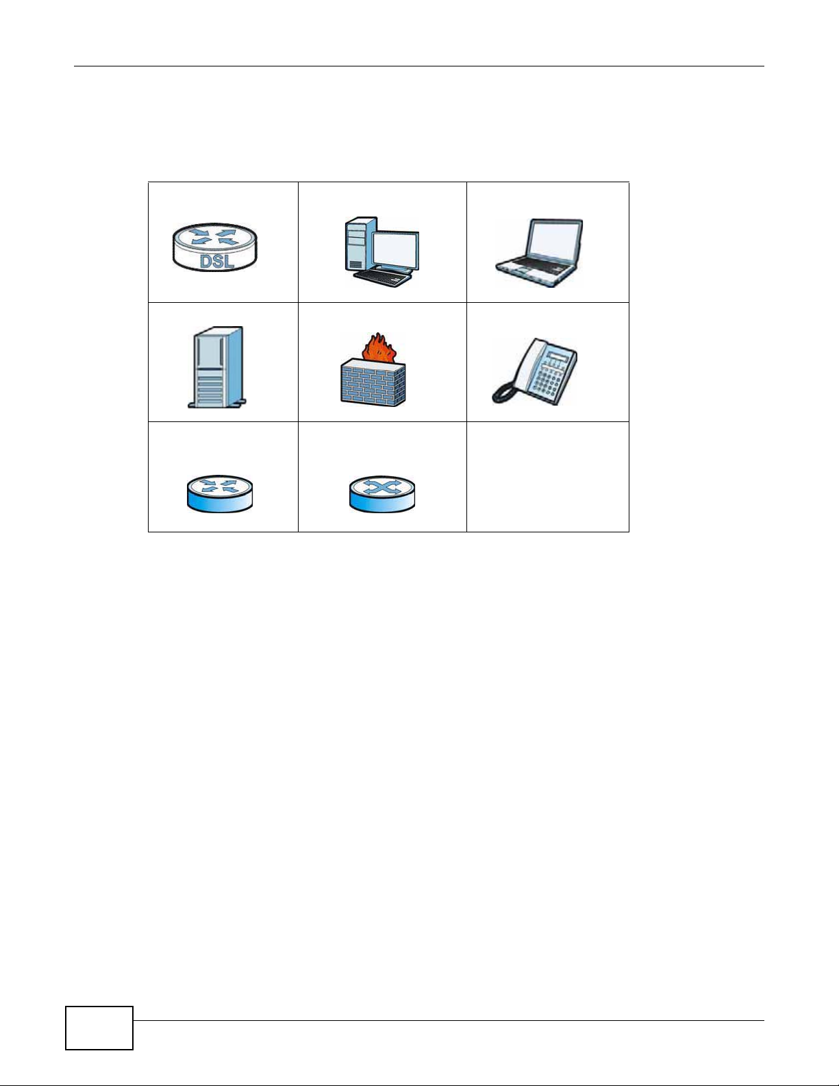
Icons Used in Figures
Figures in this User’s Guide may use the following generic icons. The ZyXEL Device icon is not an
exact representation of your device.
ZyXEL Device Computer Notebook computer
Server Firewall Teleph o n e
Router Switch
4
P-873HNUP-51B User’s Guide
Page 5

Safety Warnings
Safety Warnings
• Do NOT use this product near water, for example, in a wet basement or near a swimming pool.
• Do NOT expose your device to dampness, dust or corrosive liquids.
• Do NOT store things on the device.
• Do NOT install, use, or service this device during a thunderstorm. There is a remote risk of electric shock
from lightning.
• Connect ONLY suitable accessories to the device.
• Do NOT open the device or unit. Opening or removing covers can expose you to dangerous high voltage
points or other risks. ONLY qualified service personnel should service or disassemble this device. Please
contact your vendor for further information.
• Make sure to connect the cables to the correct ports.
• Place connecting cables carefully so that no one will step on them or stumble over them.
• Always disconnect all cables from this device before servicing or disassembling.
• Use ONLY an appropriate power adaptor or cord for your device.
• Connect the power adaptor or cord to the right supply voltage (for example, 110V AC in North America or
230V AC in Europe).
• Do NOT allow anything to rest on the power adaptor or cord and do NOT place the product where anyone can
walk on the power adaptor or cord.
• Do NOT use the device if the power adaptor or cord is damaged as it might cause electrocution.
• If the power adaptor or cord is damaged, remove it from the device and the power source.
• Do NOT attempt to repair the power adaptor or cord. Contact your local vendor to order a new one.
• Do not use the device outside, and make sure all the connections are indoors. There is a remote risk of
electric shock from lightning.
• Do NOT obstruct the device ventilation slots, as insufficient airflow may harm your device.
• Use only No. 26 AWG (American Wire Gauge) or larger telecommunication line cord.
• Antenna Warning! This device meets ETSI and FCC certification requirements when using the included
antenna(s). Only use the included antenna(s).
• This product is for indoor use only (utilisation intérieure exclusivement).
Your product is marked with this symbol, which is known as the WEEE mark. WEEE stands for Waste
Electronics and Electrical Equipment. It means that used electrical and electronic products should not be
mixed with general waste. Used electrical and electronic equipment should be treated separately.
P-873HNUP-51B User’s Guide
5
Page 6

Safety Warnings
6
P-873HNUP-51B User’s Guide
Page 7

Contents Overview
Contents Overview
User’s Guide ...........................................................................................................................19
Introducing the P-873HNUP-51B ...............................................................................................21
The Web Configurator ................................................................................................................29
Quick Start ..................................................................................................................................37
Tutorials ..................................................................................................................................... 39
Technical Reference .............................................................................................................. 63
Network Map and Status Screens .............................................................................................. 65
Broadband .................................................................................................................................. 71
Wireless .....................................................................................................................................87
Home Networking ..................................................................................................................... 115
Static Routing ........................................................................................................................... 135
Quality of Service (QoS) ..........................................................................................................139
Network Address Translation (NAT) ......................................................................................... 159
Dynamic DNS Setup ................................................................................................................175
IGMP ........................................................................................................................................179
Interface Group ........................................................................................................................189
Firewall ..................................................................................................................................... 195
MAC Filter ................................................................................................................................203
Parental Control .......................................................................................................................205
Scheduler Rules .......................................................................................................................209
Certificates ............................................................................................................................... 211
Service Control ......................................................................................................................... 223
ARP Table ................................................................................................................................225
Logs ........................................................................................................................................227
Traffic Status ...........................................................................................................................231
IGMP Status ............................................................................................................................ 235
.................................................................................................................................................236
xDSL Statistics .........................................................................................................................237
Users Configuration .................................................................................................................241
Remote Management ...............................................................................................................245
Time Settings ...........................................................................................................................251
Logs Setting ............................................................................................................................253
Firmware Upgrade ...................................................................................................................257
Configuration ............................................................................................................................ 259
Diagnostic ................................................................................................................................ 262
Troubleshooting .......................................................................................................................267
Product Specifications ..............................................................................................................273
P-873HNUP-51B User’s Guide
7
Page 8

Contents Overview
8
P-873HNUP-51B User’s Guide
Page 9

Table of Contents
Table of Contents
About This User's Guide .......................................................................................................... 3
Document Conventions ........................................................................................................... 3
Safety Warnings........................................................................................................................ 5
Contents Overview .................................................................................................................. 7
Table of Contents ..................................................................................................................... 9
Part I: User’s Guide ................................................................................ 19
Chapter 1
Introducing the P-873HNUP-51B ...........................................................................................21
1.1 Overview ..............................................................................................................................21
1.2 Ways to Manage the ZyXEL Device ....................................................................................21
1.3 Good Habits for Managing the ZyXEL Device .....................................................................22
1.4 Applications for the ZyXEL Device ......................................................................................22
1.4.1 Internet Access ...........................................................................................................22
1.4.2 HomePNA ...................................................................................................................23
1.5 LEDs (Lights) .......................................................................................................................25
1.6 The RESET Button ............................................................................................................... 26
1.7 Wireless Access ...................................................................................................................27
1.7.1 Using the WLAN/WPS Button ....................................................................................27
Chapter 2
The Web Configurator ............................................................................................................29
2.1 Overview ..............................................................................................................................29
2.1.1 Accessing the Web Configurator ................................................................................29
2.2 Web Configurator Layout .....................................................................................................32
2.2.1 Title Bar ...................................................................................................................... 32
2.2.2 Main Window ..............................................................................................................33
2.2.3 Navigation Panel ........................................................................................................33
Chapter 3
Quick Start............................................................................................................................... 37
3.1 Overview ..............................................................................................................................37
3.2 Quick Start Setup .................................................................................................................37
P-873HNUP-51B User’s Guide
9
Page 10

Table of Contents
Chapter 4
Tutorials ................................................................................................................................... 39
4.1 Overview ..............................................................................................................................39
4.2 Setting Up an ADSL PPPoE Connection .............................................................................39
4.3 HomePNA Example Setup ...................................................................................................42
4.4 Setting Up a Secure Wireless Network ................................................................................ 44
4.4.1 Configuring the Wireless Network Settings ................................................................44
4.4.2 Using WPS ................................................................................................................. 46
4.4.3 Without WPS ..............................................................................................................49
4.5 Setting Up Multiple Wireless Groups ................................................................................... 50
4.6 Setting Up NAT Port Forwarding ..........................................................................................53
4.7 Configuring Static Route for Routing to Another Network .................................................... 55
4.8 Configuring QoS Queue and Class Setup ...........................................................................57
4.9 Access the ZyXEL Device Using DDNS ..............................................................................60
4.9.1 Registering a DDNS Account on www.dyndns.org .....................................................61
4.9.2 Configuring DDNS on Your ZyXEL Device ................................................................. 61
4.9.3 Testing the DDNS Setting ........................................................................................... 61
Part II: Technical Reference...................................................................63
Chapter 5
Network Map and Status Screens .........................................................................................65
5.1 Overview ..............................................................................................................................65
5.2 The Network Map Screen ....................................................................................................65
5.3 The Status Screen ................................................................................................................67
Chapter 6
Broadband............................................................................................................................... 71
6.1 Overview ..............................................................................................................................71
6.1.1 What You Need to Know .............................................................................................71
6.1.2 Before You Begin ........................................................................................................72
6.2 The Broadband Screen ........................................................................................................73
6.2.1 Add/Edit Broadband ...................................................................................................74
6.3 The DSL Screen ................................................................................................................... 80
6.4 Technical Reference ............................................................................................................. 82
6.4.1 Encapsulation ............................................................................................................. 82
6.4.2 Multiplexing .................................................................................................................83
6.4.3 VPI and VCI ................................................................................................................ 83
6.4.4 IP Address Assignment ..............................................................................................83
6.4.5 NAT ............................................................................................................................. 84
6.4.6 Traffic Shaping ............................................................................................................84
10
P-873HNUP-51B User’s Guide
Page 11

Table of Contents
6.4.7 ATM Traffic Classes .................................................................................................... 84
6.4.8 Introduction to VLANs ................................................................................................85
Chapter 7
Wireless ................................................................................................................................... 87
7.1 Overview ..............................................................................................................................87
7.1.1 What You Can Do in this Chapter ...............................................................................87
7.1.2 What You Need to Know .............................................................................................88
7.2 The General Screen ............................................................................................................88
7.2.1 No Security ................................................................................................................. 90
7.2.2 Basic (WEP Encryption) ............................................................................................. 91
7.2.3 More Secure (WPA(2)-PSK) .......................................................................................93
7.2.4 WPA(2) Authentication ................................................................................................ 94
7.3 The More AP Screen ............................................................................................................95
7.3.1 Edit More AP .............................................................................................................96
7.4 MAC Authentication .............................................................................................................97
7.5 The WPS Screen ................................................................................................................. 98
7.6 The Others Screen .............................................................................................................100
7.7 Technical Reference ........................................................................................................... 101
7.7.1 Wireless Network Overview ...................................................................................... 101
7.7.2 Additional Wireless Terms ........................................................................................103
7.7.3 Wireless Security Overview ...................................................................................... 103
7.7.4 Signal Problems .......................................................................................................105
7.7.5 BSS ..........................................................................................................................106
7.7.6 MBSSID ....................................................................................................................106
7.7.7 Preamble Type ......................................................................................................... 107
7.7.8 WiFi Protected Setup (WPS) ....................................................................................107
Chapter 8
Home Networking .................................................................................................................115
8.1 Overview ............................................................................................................................ 115
8.1.1 What You Can Do in this Chapter ............................................................................. 115
8.1.2 What You Need To Know .......................................................................................... 116
8.1.3 Before You Begin ...................................................................................................... 117
8.2 The LAN Setup Screen ...................................................................................................... 117
8.3 The Static DHCP Screen .................................................................................................... 119
8.4 The UPnP Screen ..............................................................................................................121
8.5 Installing UPnP in Windows Example ................................................................................121
8.6 Using UPnP in Windows XP Example ...............................................................................124
8.7 The STB Vendor ID Screen ................................................................................................129
8.8 The HPNA Screen ..............................................................................................................130
8.9 The 5th Ethernet Port Screen ............................................................................................130
8.10 The LAN VLAN Screen ....................................................................................................131
P-873HNUP-51B User’s Guide
11
Page 12

Table of Contents
8.11 Technical Reference .........................................................................................................132
8.11.1 LANs, WANs and the ZyXEL Device ...................................................................... 132
8.11.2 DHCP Setup ........................................................................................................... 132
8.11.3 DNS Server Addresses ...........................................................................................133
8.11.4 LAN TCP/IP ............................................................................................................ 133
Chapter 9
Static Routing........................................................................................................................ 135
9.1 Overview ...........................................................................................................................135
9.2 The Routing Screen ...........................................................................................................136
9.2.1 Add/Edit Static Route ...............................................................................................137
Chapter 10
Quality of Service (QoS).......................................................................................................139
10.1 Overview .........................................................................................................................139
10.1.1 What You Can Do in this Chapter ...........................................................................139
10.2 What You Need to Know .................................................................................................. 140
10.3 The Quality of Service General Screen ...........................................................................141
10.4 The Queue Setup Screen ................................................................................................143
10.4.1 Adding a QoS Queue ............................................................................................ 144
10.5 The Class Setup Screen .................................................................................................145
10.5.1 Add/Edit QoS Class ............................................................................................... 147
10.6 The QoS Policer Setup Screen ........................................................................................150
10.6.1 Add/Edit a QoS Policer ..........................................................................................151
10.7 The QoS Monitor Screen ................................................................................................152
10.8 Technical Reference .........................................................................................................153
Chapter 11
Network Address Translation (NAT).................................................................................... 159
11.1 Overview ..........................................................................................................................159
11.1.1 What You Can Do in this Chapter ...........................................................................159
11.1.2 What You Need To Know ........................................................................................159
11.2 The Port Forwarding Screen ...........................................................................................160
11.2.1 Add/Edit Port Forwarding .......................................................................................162
11.3 The Applications Screen .................................................................................................. 163
11.3.1 Add New Application ...............................................................................................164
11.4 The Port Triggering Screen ..............................................................................................164
11.4.1 Add/Edit Port Triggering Rule ................................................................................166
11.5 The DMZ Screen ..............................................................................................................167
11.6 The ALG Screen ...............................................................................................................168
11.7 The Sessions Screen .......................................................................................................169
11.8 Technical Reference .........................................................................................................169
11.8.1 NAT Definitions ....................................................................................................... 169
12
P-873HNUP-51B User’s Guide
Page 13

Table of Contents
11.8.2 What NAT Does ...................................................................................................... 170
11.8.3 How NAT Works ......................................................................................................171
11.8.4 NAT Application ......................................................................................................172
Chapter 12
Dynamic DNS Setup .............................................................................................................175
12.1 Overview ..........................................................................................................................175
12.1.1 What You Can Do in this Chapter ...........................................................................176
12.1.2 What You Need To Know ........................................................................................ 176
12.2 The DNS Entry Screen .....................................................................................................176
12.2.1 Add/Edit DNS Entry ................................................................................................177
12.3 The Dynamic DNS Screen ............................................................................................... 178
Chapter 13
IGMP....................................................................................................................................... 179
13.1 Overview ..........................................................................................................................179
13.1.1 What You Can Do in this Chapter ...........................................................................179
13.1.2 What You Need to Know .........................................................................................179
13.2 The IGMP General Screen ...............................................................................................181
13.3 IGMP Filter Configuration .................................................................................................182
13.3.1 IGMP Host Limitation Edit ....................................................................................... 184
13.3.2 IGMP Service Add ..................................................................................................184
13.3.3 IGMP Host Limitation Add ......................................................................................185
13.4 IGMP ACL Configuration .................................................................................................. 186
13.4.1 IGMP ACL Add ....................................................................................................... 187
Chapter 14
Interface Group ..................................................................................................................... 189
14.1 Overview ..........................................................................................................................189
14.2 The Interface Group Screen ............................................................................................. 189
14.2.1 Interface Group Configuration ................................................................................190
14.2.2 Interface Grouping Criteria ....................................................................................192
Chapter 15
Firewall .................................................................................................................................. 195
15.1 Overview ..........................................................................................................................195
15.1.1 What You Can Do in this Chapter ...........................................................................195
15.1.2 What You Need to Know .........................................................................................195
15.2 The Firewall Screen .........................................................................................................197
15.3 The Protocol Screen ....................................................................................................... 197
15.3.1 Add a Protocol ......................................................................................................199
15.4 The Access Control Screen .............................................................................................200
15.4.1 Add/Edit an ACL Rule ...........................................................................................201
P-873HNUP-51B User’s Guide
13
Page 14

Table of Contents
Chapter 16
MAC Filter.............................................................................................................................. 203
16.1 Overview .........................................................................................................................203
16.2 The MAC Filter Screen .....................................................................................................203
Chapter 17
Parental Control.................................................................................................................... 205
17.1 Overview ..........................................................................................................................205
17.2 The Parental Control Screen ............................................................................................205
17.2.1 Add/Edit Parental Control Rule ...............................................................................206
Chapter 18
Scheduler Rules....................................................................................................................209
18.1 Overview ..........................................................................................................................209
18.2 The Scheduler Rules Screen ...........................................................................................209
18.2.1 Add/Edit a Schedule ............................................................................................... 210
Chapter 19
Certificates ............................................................................................................................ 211
19.1 Overview .......................................................................................................................... 211
19.1.1 What You Can Do in this Chapter ........................................................................... 211
19.2 What You Need to Know .................................................................................................. 211
19.3 The Local Certificates Screen .......................................................................................... 212
19.3.1 Create Certificate Request .................................................................................... 213
19.3.2 Load Signed Certificate .........................................................................................214
19.3.3 Import Certificate ...................................................................................................215
19.3.4 Certificate Details ..................................................................................................217
19.4 The Trusted CA Screen ...................................................................................................219
19.4.1 View Trusted CA Certificate ....................................................................................220
19.4.2 Import Trusted CA Certificate .................................................................................221
Chapter 20
Service Control ..................................................................................................................... 223
20.1 Overview ..........................................................................................................................223
20.2 The Service Control Screen ............................................................................................. 223
Chapter 21
ARP Table .............................................................................................................................. 225
21.1 Overview ..........................................................................................................................225
21.1.1 How ARP Works ..................................................................................................... 225
21.2 ARP Table Screen ............................................................................................................225
14
P-873HNUP-51B User’s Guide
Page 15

Table of Contents
Chapter 22
Logs ...................................................................................................................................... 227
22.1 Overview ..........................................................................................................................227
22.1.1 What You Can Do in this Chapter ...........................................................................227
22.1.2 What You Need To Know ........................................................................................ 227
22.2 The System Log Screen ................................................................................................... 228
22.3 The Security Log Screen ..................................................................................................229
Chapter 23
Traffic Status ........................................................................................................................ 231
23.1 Overview ..........................................................................................................................231
23.1.1 What You Can Do in this Chapter ...........................................................................231
23.2 The WAN Status Screen ..................................................................................................231
23.3 The LAN Status Screen ....................................................................................................233
23.4 The HPNA Status Screen ................................................................................................. 234
Chapter 24
IGMP Status .......................................................................................................................... 235
24.1 Overview ..........................................................................................................................235
24.1.1 What You Can Do in this Chapter ...........................................................................235
24.2 The IGMP Group Screen ................................................................................................. 235
24.3 IGMP Statistics Screen ....................................................................................................236
................................................................................................................................................ 236
Chapter 25
xDSL Statistics...................................................................................................................... 237
25.1 The xDSL Statistics Screen ..............................................................................................237
Chapter 26
Users Configuration .............................................................................................................241
26.1 Overview .........................................................................................................................241
26.2 The Users Configuration Screen ...................................................................................... 241
26.2.1 Add/Edit a Users Account ....................................................................................... 242
Chapter 27
Remote Management............................................................................................................ 245
27.1 Overview ..........................................................................................................................245
27.1.1 What You Can Do in this Chapter ...........................................................................245
27.2 The TR-069 Clients Screen .............................................................................................. 245
27.3 The TR-064 Screen ..........................................................................................................247
27.4 The SNMP Agent Screen ................................................................................................. 247
P-873HNUP-51B User’s Guide
15
Page 16

Table of Contents
Chapter 28
Time Settings ........................................................................................................................ 251
28.1 Overview ..........................................................................................................................251
28.2 The Time Setting Screen ................................................................................................251
Chapter 29
Logs Setting ......................................................................................................................... 253
29.1 Overview .........................................................................................................................253
29.2 The Logs Setting Screen ..................................................................................................253
29.2.1 Example E-mail Log ...............................................................................................255
Chapter 30
Firmware Upgrade ................................................................................................................257
30.1 Overview ..........................................................................................................................257
30.2 The Firmware Screen .......................................................................................................257
Chapter 31
Configuration ........................................................................................................................ 259
31.1 Overview ..........................................................................................................................259
31.2 The Configuration Screen ................................................................................................259
31.3 The Reboot Screen ..........................................................................................................261
Chapter 32
Diagnostic ............................................................................................................................. 262
32.1 Overview ..........................................................................................................................262
32.1.1 What You Can Do in this Chapter ...........................................................................262
32.2 What You Need to Know .................................................................................................. 262
32.3 Ping & TraceRoute & NsLookup ......................................................................................263
32.4 802.1ag ............................................................................................................................264
32.5 OAM Ping Test ................................................................................................................. 265
Chapter 33
Troubleshooting.................................................................................................................... 267
33.1 Power, Hardware Connections, and LEDs ....................................................................... 267
33.2 ZyXEL Device Access and Login ..................................................................................... 268
33.3 Internet Access ................................................................................................................269
33.4 Wireless Internet Access ..................................................................................................271
Chapter 34
Product Specifications.........................................................................................................273
34.1 Hardware Specifications ...................................................................................................273
34.2 Firmware Specifications ...................................................................................................274
16
P-873HNUP-51B User’s Guide
Page 17

Table of Contents
Appendix A Setting up Your Computer’s IP Address........................................................... 279
Appendix B IP Addresses and Subnetting........................................................................... 301
Appendix C Pop-up Windows, JavaScript and Java Permissions ....................................... 309
Appendix D Wireless LANs.................................................................................................. 319
Appendix E Services............................................................................................................ 333
Appendix F Open Software Announcements....................................................................... 337
Appendix G Legal Information .............................................................................................347
Index ...................................................................................................................................... 351
P-873HNUP-51B User’s Guide
17
Page 18

Table of Contents
18
P-873HNUP-51B User’s Guide
Page 19

PART I
User’s Guide
19
Page 20

20
Page 21

1.1 Overview
The P-873HNUP-51B is a wireless VDSL router and Gigabit Ethernet gateway with Home Phoneline
Networking Alliance (HPNA) capability. It has two DSL ports and a Gigabit Ethernet port for superfast Internet access over analog (POTS) telephone lines. If the DSLAM of the ISP supports bonding
function, the two DSL ports on the P-873HNUP-51B can be connected to two separate telephone
jacks to provide increased throughput at longer distances. The ZyXEL Device supports both Packet
Transfer Mode (PTM) and Asynchronous Transfer Mode (ATM). It is backward compatible with ADSL,
ADSL2 and ADSL2+ in case VDSL is not available. The P-873HNUP-51B also provides IEEE
802.11b/g/n wireless networking to extend the range of your existing wired network without
additional wiring.
Please refer to the following description of the product name format.
CHAPTER 1
Introducing the P-873HNUP-51B
• “H” denotes an integrated 4-port switch (hub).
• “N” denotes 802.11n draft 2.0. The “N” models support 802.11n wireless connection mode.
• “U” denotes a USB port. The ZyXEL Device supports a flash disk (FAT16/FAT32 format), which
FTP clients can access.
• “P” denotes a device that has Home Phoneline Networking Alliance (HPNA) capability.
• Model names ending in “1”, for example P-873HNUP-51, denote a device that works over the
analog telephone system, POTS (Plain Old Telephone Service). The DSL RJ-14 connects to your
ADSL-enabled telephone lines.
Only use firmware for your ZyXEL Device’s specific model. Refer to the
label on the bottom of your ZyXEL Device.
See Chapter 34 on page 273 for a full list of features.
1.2 Ways to Manage the ZyXEL Device
Use any of the following methods to manage the ZyXEL Device.
• Web Configurator. This is recommended for everyday management of the ZyXEL Device using a
(supported) web browser.
• TR-069. This is an auto-configuration server used to remotely configure your device.
P-873HNUP-51B User’s Guide 21
Page 22

Chapter 1 Introducing the P-873HNUP-51B
1.3 Good Habits for Managing the ZyXEL Device
Do the following things regularly to make the ZyXEL Device more secure and to manage the ZyXEL
Device more effectively.
• Change the password. Use a password that’s not easy to guess and that consists of different
types of characters, such as numbers and letters.
• Write down the password and put it in a safe place.
• Back up the configuration (and make sure you know how to restore it). Restoring an earlier
working configuration may be useful if the device becomes unstable or even crashes. If you
forget your password, you will have to reset the ZyXEL Device to its factory default settings. If
you backed up an earlier configuration file, you would not have to totally re-configure the ZyXEL
Device. You could simply restore your last configuration.
1.4 Applications for the ZyXEL Device
Here are some example uses for which the ZyXEL Device is well suited.
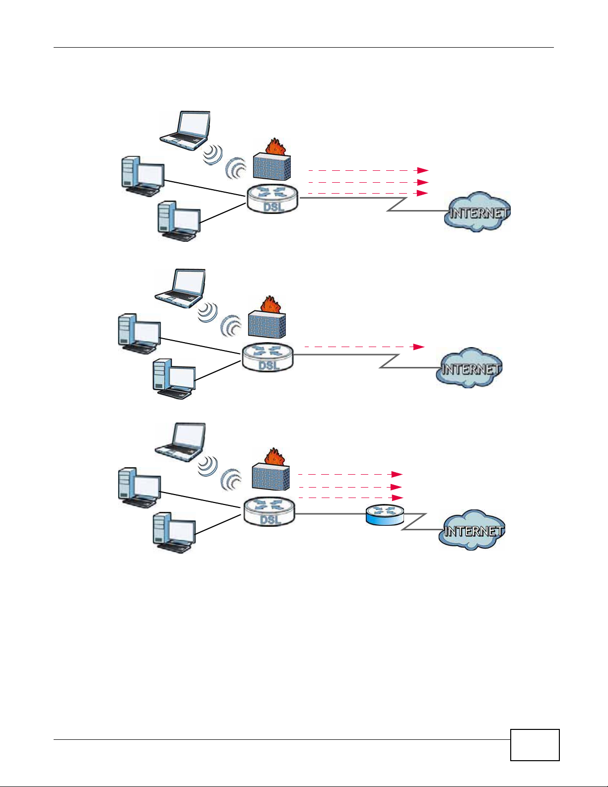
1.4.1 Internet Access
Your ZyXEL Device provides shared Internet access by connecting the DSL port to the DSL or
MODEM jack on a splitter or your telephone jack. You can have up to eight WAN services over one
ADSL, VDSL or Ethernet WAN line. The ZyXEL Device cannot work in ADSL, VDSL and Ethernet
WAN mode at the same time.
Note: The ADSL, VDSL and Ethernet WAN lines share the same eight WAN (layer-3)
interfaces that you configure in the ZyXEL Device. Refer to Section 6.2 on page 73
for the Network Settings> Broadband screen.
22
P-873HNUP-51B User’s Guide
Page 23
Chapter 1 Introducing the P-873HNUP-51B
WLAN
PPPoE
IPoE
Bridging
WAN
ADSL
IPoA / PPPoA
WAN
Ethernet
LAN
PPPoE
IPoE
WAN
LAN
Bridging
LAN
WLAN
WLAN
A
A
A
Computers can connect to the ZyXEL Device’s LAN ports (or wirelessly).
Figure 1 ZyXEL Device’s Internet Access Application
ADSL / VDSL
You can also configure IP filtering on the ZyXEL Device for secure Internet access. When the IP filter
is on, all incoming traffic from the Internet to your network is blocked by default unless it is
initiated from your network. This means that probes from the outside to your network are not
allowed, but you can safely browse the Internet and download files.
1.4.2 HomePNA
DSL
The ZyXEL Device complies with HomePNA (Home Phoneline Networking Alliance, also known as
HPNA) 3.1, a home networking technology for carrying data over existing coaxial cables and
telephone wiring.
P-873HNUP-51B User’s Guide
23
Page 24
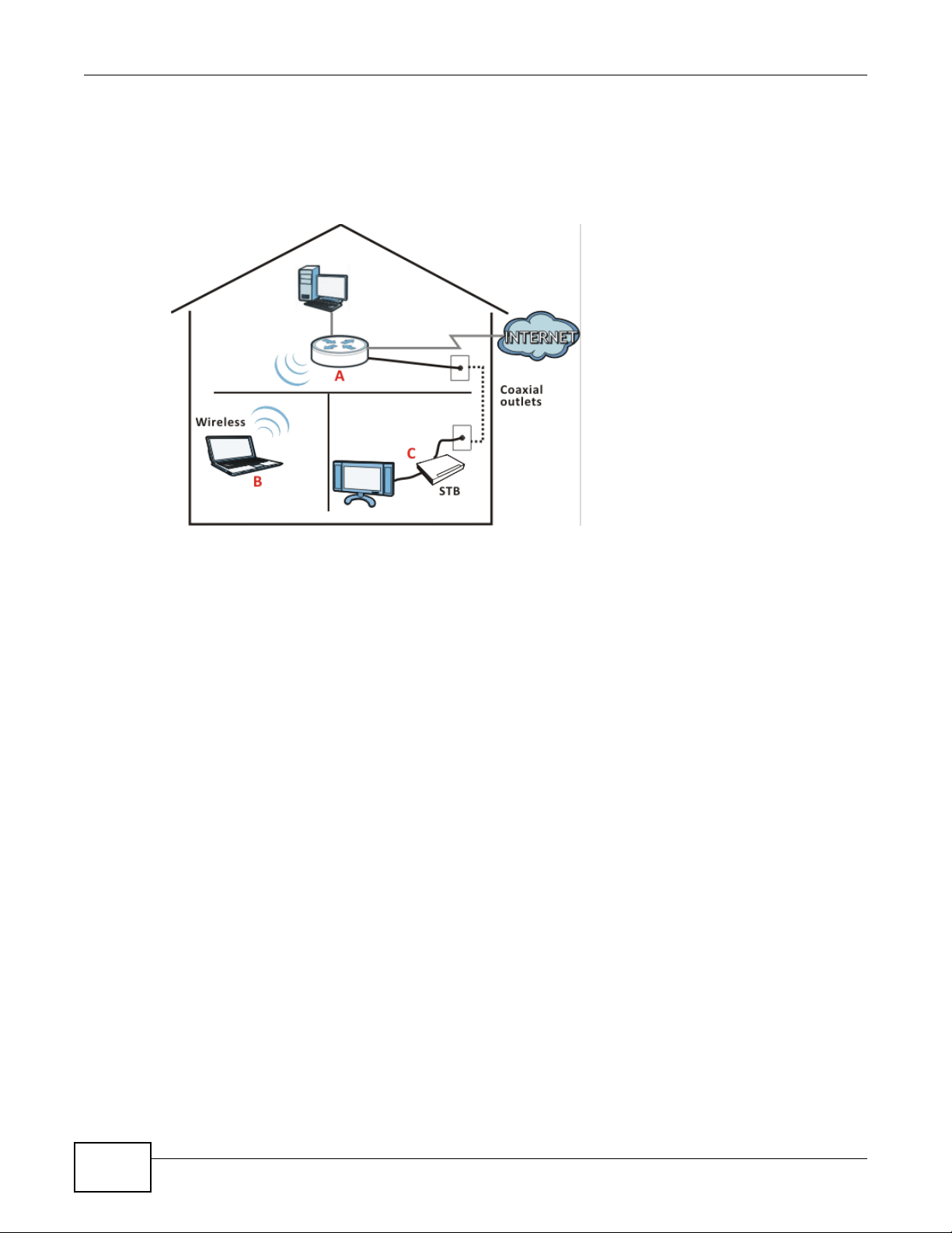
Chapter 1 Introducing the P-873HNUP-51B
The figure below shows your ZyXEL Device (A) connecting to a phone line outlet for DSL Internet
access and a coaxial outlet to relay Internet connectivity to other coaxial outlets in the building. The
laptop (B) connects wirelessly to the ZyXEL Device. The set-up box (C) connects into a coaxial
outlet in another part of the house for access to online videos.
Figure 2 HomePNA Application
24
P-873HNUP-51B User’s Guide
Page 25
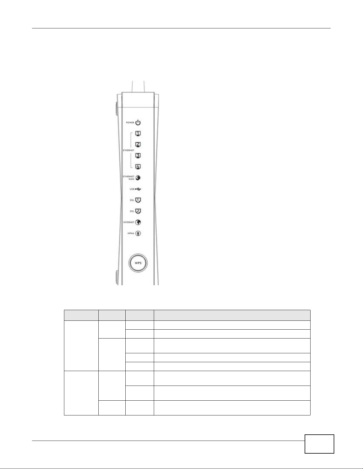
1.5 LEDs (Lights)
The following graphic displays the labels of the LEDs.
Figure 3 LEDs on the Device
Chapter 1 Introducing the P-873HNUP-51B
None of the LEDs are on if the ZyXEL Device is not receiving power.
Table 1 LED Descriptions
LED COLOR STATUS DESCRIPTION
POWER Green On The ZyXEL Device is receiving power and ready for use.
ETHERNET
1-4
P-873HNUP-51B User’s Guide
Blinking The ZyXEL Device is self-testing.
Red On The ZyXEL Device detected an error while self-testing, or there
is a device malfunction.
Off The ZyXEL Device is not receiving power.
Blinking Firmware upgrade is in progress.
Green On The ZyXEL Device has a successful 100 Mbps Ethernet
connection with a device on the Local Area Network (LAN).
Blinking The ZyXEL Device is sending or receiving data to/from the LAN
at 100 Mbps.
Off The ZyXEL Device does not have an Ethernet connection with
the LAN.
25
Page 26

Chapter 1 Introducing the P-873HNUP-51B
Table 1 LED Descriptions (continued)
LED COLOR STATUS DESCRIPTION
ETHERNET
WAN
USB Green On The ZyXEL Device recognizes a USB connection.
DSL1,2 Green On The ADSL line is up.
INTERNET Green On The ZyXEL Device has an IP connection but no traffic.
HPNA Green On The ZyXEL Device is connected to an HPNA-equipped device
WLAN/WPS Green On The wireless network is activated.
Green On The Gigabit Ethernet connection is working.
Blinking The ZyXEL Device is sending or receiving data to/from the
Off There is no Gigabit Ethernet link.
Blinking The ZyXEL Device is sending/receiving data to /from the USB
Off The ZyXEL Device does not detect a USB connection.
Blinking The ZyXEL Device is initializing the ADSL line.
Off The ADSL line is down.
Orange On The VDSL line is up.
Blinking The ZyXEL Device is initializing the VDSL line.
Off The VDSL line is down.
Blinking The ZyXEL Device is sending or receiving IP traffic.
Off There is no Internet connection or the gateway is in bridged
Blinking Data is transmitting over the HPNA cable.
Off No HPNA device is connected.
Blinking The ZyXEL Device is communicating with other wireless clients.
Green
and
Orange
Blinking The ZyXEL Device is setting up a WPS connection.
Off The wireless network is not activated.
Gigabit Ethernet link.
device connected to it.
Your device has a WAN IP address (either static or assigned by
a DHCP server), PPP negotiation was successfully completed (if
used) and the DSL connection is up.
mode.
through the coaxial cable.
1.6 The RESET Button
If you forget your password or cannot access the web configurator, you will need to use the RESET
button at the back of the device to reload the factory-default configuration file. This means that you
will lose all configurations that you had previously and the password will be reset to “1234”.
1 Make sure the POWER LED is on (not blinking).
2 To set the device back to the factory default settings, press the RESET button for ten seconds or
until the POWER LED begins to blink and then release it. When the POWER LED begins to blink,
the defaults have been restored and the device restarts.
26
P-873HNUP-51B User’s Guide
Page 27
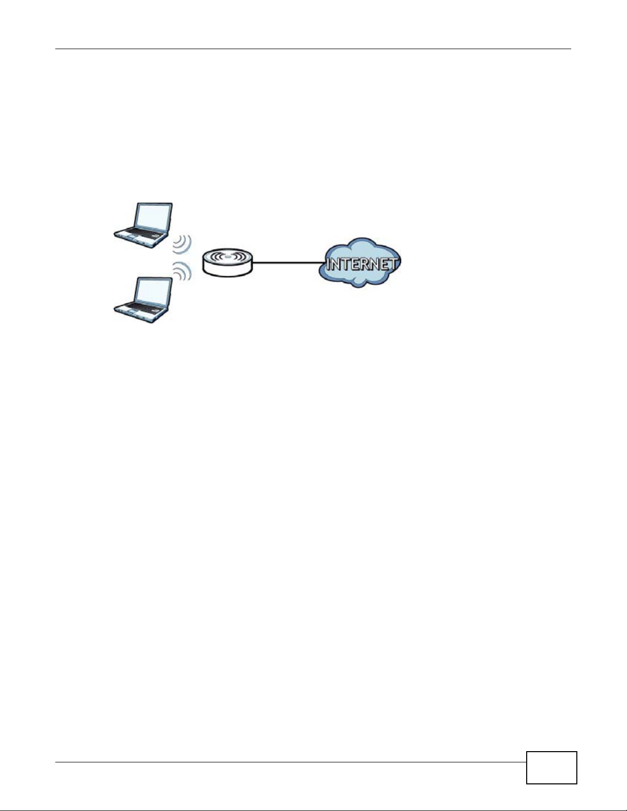
1.7 Wireless Access
The ZyXEL Device is a wireless Access Point (AP) for wireless clients, such as notebook computers
or PDAs and iPads. It allows them to connect to the Internet without having to rely on inconvenient
Ethernet cables.
You can configure your wireless network in either the built-in Web Configurator, or using the WPS
button.
Figure 4 Wireless Access Example
Chapter 1 Introducing the P-873HNUP-51B
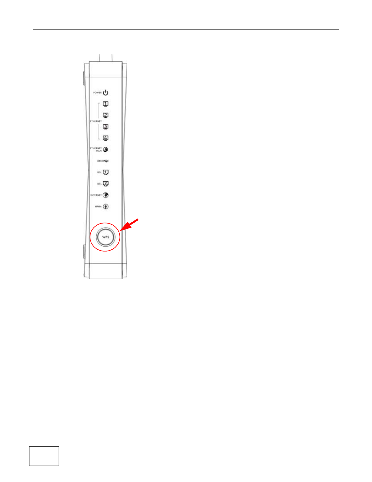
1.7.1 Using the WLAN/WPS Button
If the wireless network is turned off, press the WLAN/WPS button on the front of the ZyXEL
Device for two seconds. Once the WLAN/WPS LED turns green, the wireless network is active.
You can also use the WLAN/WPS button to quickly set up a secure wireless connection between
the ZyXEL Device and a WPS-compatible client by adding one device at a time.
To activate WPS:
1 Make sure the POWER LED is on and not blinking.
P-873HNUP-51B User’s Guide
27
Page 28
Chapter 1 Introducing the P-873HNUP-51B
2 Press the WLAN/WPS button for five seconds and release it.
3 Press the WPS button on another WPS-enabled device within range of the ZyXEL Device. The
WLAN/WPS LED flashes green and orange while the ZyXEL Device sets up a WPS connection with
the other wireless device.
4 Once the connection is successfully made, the WLAN/WPS LED shines green.
To turn off the wireless network, press the WLAN/WPS button on the front of the ZyXEL Device for
one to five seconds. The WLAN/WPS LED turns off when the wireless network is off.
28
P-873HNUP-51B User’s Guide
Page 29

2.1 Overview
The web configurator is an HTML-based management interface that allows easy device setup and
management via Internet browser. Use Internet Explorer 6.0 and later versions or Mozilla Firefox 3
and later versions or Safari 2.0 and later versions. The recommended screen resolution is 1024 by
768 pixels.
In order to use the web configurator you need to allow:
• Web browser pop-up windows from your device. Web pop-up blocking is enabled by default in
Windows XP SP (Service Pack) 2.
• JavaScript (enabled by default).
• Java permissions (enabled by default).
CHAPTER 2
The Web Configurator
See Appendix C on page 309 if you need to make sure these functions are allowed in Internet
Explorer.
2.1.1 Accessing the Web Configurator
1 Make sure your ZyXEL Device hardware is properly connected (refer to the Quick Start Guide).
2 Launch your web browser. If the ZyXEL Device does not automatically re-direct you to the login
screen, go to http://192.168.1.1.
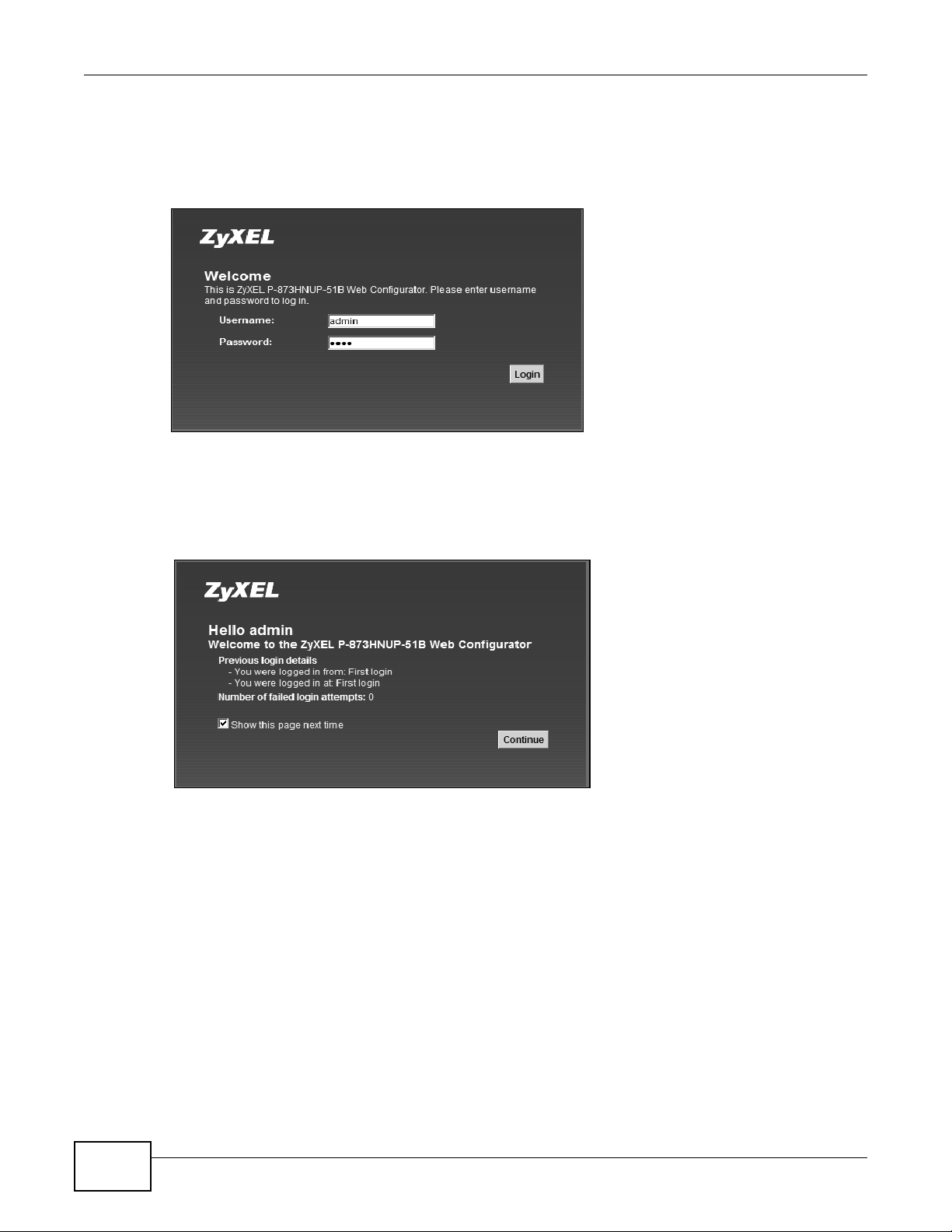
3 A password screen displays. To access the administrative web configurator and manage the ZyXEL
Device, type the default username admin and password 1234 in the password screen and click
Login. If advanced account security is enabled (see Section 26.2 on page 241) the number of dots
that appears when you type the password changes randomly to prevent anyone watching the
P-873HNUP-51B User’s Guide 29
Page 30
Chapter 2 The Web Configurator
password field from knowing the length of your password. If you have changed the password, enter
your password and click Login. For security reasons, you will be temporarily denied access to the
ZyXEL Device for a period of time (15 minutes by default) if you have entered the incorrect
username and password for a certain number of times (three times by default).
Figure 5 Password Screen
4 A welcome screen appears showing a summary of your last login, such as the time, number of
failed login attempts, and when the password expires. It also shows if you are logged on from an IP
address. Select Show this page next time to see the welcome screen on your next login.
Otherwise, deselect it. Click Continue.
Figure 6 Welcome Screen
30
P-873HNUP-51B User’s Guide
Page 31

5 The Network Map page appears.
Figure 7 Network Map
Chapter 2 The Web Configurator
Note: For security reasons, the ZyXEL Device automatically logs you out if you do not use
the web configurator for ten minutes (default). If this happens, log in again.
6 Click Status to display the Status screen, where you can view the ZyXEL Device’s interface and
system information.
Note: It is strongly recommended you change the default password. You can do so in the
Maintenance > Users Configuration screen. See Chapter 26 on page 241 for
more information.
P-873HNUP-51B User’s Guide
31
Page 32

Chapter 2 The Web Configurator
B
C
A
2.2 Web Configurator Layout
Figure 8 Screen Layout
As illustrated above, the main screen is divided into these parts:
• A - title bar
• B - main window
• C - navigation panel
2.2.1 Title Bar
The title bar provides some icons in the upper right corner.
32
P-873HNUP-51B User’s Guide
Page 33

The icons provide the following functions.
Table 2 Web Configurator Icons in the Title Bar
ICON DESCRIPTION
2.2.2 Main Window
The main window displays information and configuration fields. It is discussed in the rest of this
document.
After you click Status on the Network Map page, the Status screen is displayed. See Chapter 5
on page
If you click Virtual Device on the Status screen, a visual graphic appears, showing the connection
status of the ZyXEL Device’s ports. The connected ports are in color and disconnected ports are
gray.
for more information about the Status screen.
67
Chapter 2 The Web Configurator
Quick Start: Click this icon to open screens where you can configure the ZyXEL
Device’s time zone Internet access, and wireless settings.
Logout: Click this icon to log out of the web configurator.
If you click Network Map on the Status screen, the Network Map screen appears. See Chapter 5
on page 65 for more information about the Network Map screen.
2.2.3 Navigation Panel
Use the menu items on the navigation panel to open screens to configure ZyXEL Device features.
The following tables describe each menu item.
Table 3 Navigation Panel Summary
LINK TAB FUNCTION
Network Map This screen shows the network status of the ZyXEL Device and computers/
Network Settings
Broadband Broadband Use this screen to enable PTM over ADSL, view and configure ISP
DSL Use this screen to enable and configure the DSL bonding function.
Wireless General Use this screen to configure the wireless LAN settings and WLAN
More AP Use this screen to configure multiple BSSs on the ZyXEL Device.
MAC
Authentication
WPS Use this screen to configure and view your WPS (Wi-Fi Protected Setup)
Others Use this screen to configure advanced wireless settings.
devices connected to it.
parameters, WAN IP address assignment, and other advanced properties.
You can also add new WAN connections.
authentication/security settings.
Use this screen to block or allow wireless traffic from wireless devices of
certain SSIDs and MAC addresses to the ZyXEL Device.
settings.
P-873HNUP-51B User’s Guide
33
Page 34

Chapter 2 The Web Configurator
Table 3 Navigation Panel Summary (continued)
LINK TAB FUNCTION
Home
Networking
Routing Static Route Use this screen to view and set up static routes on the ZyXEL Device.
QoS General Use this screen to enable QoS and traffic prioritizing. You can also
NAT Port Forwarding Use this screen to make your local servers visible to the outside world.
DNS Setting DNS Entry Use this screen to view and configure DNS routes.
IGMP Setting General Use this screen to configure general IGMP proxy and IGMP packet
Interface
Group
Security Settings
Firewall General Use this screen to configure the security level of your firewall.
MAC Filter MAC Filter Use this screen to block or allow traffic from devices of certain MAC
LAN Setup Use this screen to configure LAN TCP/IP settings, and other advanced
properties.
Static DHCP Use this screen to assign specific IP addresses to individual MAC
addresses.
UPnP Use this screen to turn UPnP and UPnP NAT-T on or off.
STB Vendor ID Use this screen to have the ZyXEL Device automatically create static
HPNA Use this screen to enable or disable the HPNA port.
5th Ethernet
Port
LAN VLAN Use this screen to control the VLAN ID and IEEE 802.1p priority tags of
Policy
Forwarding
Queue Setup Use this screen to configure QoS queues.
Class Setup Use this screen to define a classifier.
Policer Setup Use these screens to configure QoS policers.
Monitor Use this screen to view QoS packets statistics.
Applications Use this screen to configure servers behind the ZyXEL Device.
Port Triggering Use this screen to change your ZyXEL Device’s port triggering settings.
DMZ Use this screen to configure a default server which receives packets from
ALG Use this screen to enable or disable SIP ALG.
Sessions Use this screen to limit the number of NAT sessions a single client can
Dynamic DNS Use this screen to allow a static hostname alias for a dynamic IP address.
IGMP Filter Use this screen to control IGMP access.
IGMP ACL Use this screen to block or allow access to specific multicast media
Interface Group Use this screen to map a port to a PVC or bridge group.
Protocol Use this screen to add or remove predefined Internet services and
Access Control Use this screen to enable specific traffic directions for network services.
DHCP entries for Set Top Box (STB) devices when they request IP
addresses.
Use this screen to configure the Ethernet WAN port as a LAN port.
traffic sent out through individual LAN ports.
Use this screen to configure policy routing on the ZyXEL Device.
configure the QoS rules and actions.
ports that are not specified in the Port Forwarding screen.
establish.
processing settings.
channels.
configure firewall rules.
addresses to the ZyXEL Device.
34
P-873HNUP-51B User’s Guide
Page 35

Chapter 2 The Web Configurator
Table 3 Navigation Panel Summary (continued)
LINK TAB FUNCTION
Parental
Control
Scheduler Rule Scheduler Rule Use this screen to configure the days and times when a configured
Certificates Local Certificates Use this screen to view a summary list of certificates and manage
Service Control Service Control Use this screen to control service access to the ZyXEL Device.
System Monitor
ARP Table ARP Table Use this screen to view the ARP table. It displays the IP and MAC address
Log System Log Use this screen to view the status of events that occurred to the ZyXEL
Traffic Status WAN Use this screen to view the status of all network traffic going through the
IGMP Group
Status
xDSL Statistics xDSL Statistics Use this screen to view the ZyXEL Device’s xDSL traffic statistics.
Maintenance
Users
Configuration
Remote MGMT TR-069 Client Use this screen to configure the ZyXEL Device to be managed by an Auto
Time Setting Time Setting Use this screen to change your ZyXEL Device’s time and date.
Log Setting Log Setting Use this screen to change your ZyXEL Device’s log settings.
Firmware
Upgrade
Configuration Configuration Use this screen to backup and restore your device’s configuration
Reboot Reboot Use this screen to reboot the ZyXEL Device without turning the power off.
Parental Control Use this screen to block web sites with the specific URL.
restriction (such as parental control) is enforced.
certificates and certification requests.
Trusted CA
Security Log Use this screen to view the login record of the ZyXEL Device. You can
LAN Use this screen to view the status of all network traffic going through the
HPNA Use this screen to view the status of all network traffic going through the
IGMP Group Use this screen to view the status of all IGMP settings on the ZyXEL
IGMP Statistics Use this screen to view the ZyXEL Device’s IGMP multicast group and
Users
Configuration
TR-064 Client Use this screen to enable management via TR-064 on the LAN.
SNMP Agent Use this screen to configure your ZyXEL Device’s settings for Simple
Firmware
Upgrade
Use this screen to view and manage the list of the trusted CAs.
of each DHCP connection.
Device. You can export or e-mail the logs.
export or e-mail the logs.
WAN port of the ZyXEL Device.
LAN ports of the ZyXEL Device.
HPNA port of the ZyXEL Device.
Device.
IGMP traffic statistics.
Use this screen to add and configure user accounts on the ZyXEL Device.
Configuration Server (ACS).
Network Management Protocol management.
Use this screen to upload firmware to your device.
(settings) or reset the factory default settings.
P-873HNUP-51B User’s Guide
35
Page 36

Chapter 2 The Web Configurator
Table 3 Navigation Panel Summary (continued)
LINK TAB FUNCTION
Diagnostic Ping &
Use this screen to identify problems with the DSL connection. You can use
Trac e R o u t e &
NsLookup
802.1ag Use this screen to configure CFM (Connectivity Fault Management) MD
OAM Ping These screen displays information to help you identify problems with the
Ping, TraceRoute, or Nslookup to help you identify problems.
(maintenance domain) and MA (maintenance association), perform
connectivity tests and view test reports.
DSL connection.
36
P-873HNUP-51B User’s Guide
Page 37

3.1 Overview
Use the Quick Start screens to configure the ZyXEL Device’s time zone and basic Internet access
and wireless settings.
Note: See the technical reference chapters (starting on page 63) for background
information on the features in this chapter.
3.2 Quick Start Setup
1 Click the Click Start icon in the top right corner of the web configurator to open the quick start
screens. Select the time zone of the ZyXEL Device’s location and click Next.
Figure 9 Time Zone
CHAPTER 3
Quick Start
P-873HNUP-51B User’s Guide 37
Page 38

Chapter 3 Quick Start
2 Enter your PPPoE account’s user name and password exactly as provided by your Internet Service
Provider (ISP). If your ISP also gave you static IP address settings to use, select Yes and enter
them in the fields that display. Click Next.
Figure 10 Internet Connection
3 Turn the wireless LAN on or off. If you keep it on, record the security settings so you can configure
your wireless clients to connect to the ZyXEL Device. Click Save.
Figure 11 Internet Connection
4 Your ZyXEL Device saves your settings and attempts to connect to the Internet.
38
P-873HNUP-51B User’s Guide
Page 39

4.1 Overview
This chapter shows you how to use the ZyXEL Device’s various features.
• Setting Up an ADSL PPPoE Connection, see page 39
• HomePNA Example Setup, see page 42
• Setting Up a Secure Wireless Network, see page 44
• Setting Up Multiple Wireless Groups, see page 50
• Setting Up NAT Port Forwarding, see page 53
• Configuring Static Route for Routing to Another Network, see page 55
• Configuring QoS Queue and Class Setup, see page 57
• Access the ZyXEL Device Using DDNS, see page 60
CHAPTER 4
Tutorials
4.2 Setting Up an ADSL PPPoE Connection
This tutorial shows you how to set up your Internet connection using the Web Configurator.
If you connect to the Internet through an ADSL connection, use the information from your Internet
Service Provider (ISP) to configure the ZyXEL Device. Be sure to contact your service provider for
any information you need to configure the Broadband screens.
1 Click Network Settings > Broadband to open the following screen. Click Add New WAN
Interface.
P-873HNUP-51B User’s Guide 39
Page 40

Chapter 4 Tutorials
2 In this example, the DSL connection has the following information.
General
ATM PVC Configuration
Account Information
Connection Name MyDSLConnection
Type ADSL over ATM
Connection Mode Routing
Encapsulation PPPoE
VPI/VCI 36/48
Encapsulation Mode LLC/SNAP-Bridging
Service Category UBR without PCR
PPP User Name 1234@DSL-Ex.com
PPP Password ABCDEF!
PPPoE Service Name MyDSL
Static IP Address 192.168.1.32
Others PPPoE Passthrough: Disabled
NAT: Enabled
IGMP Multicast Proxy: Enabled
Apply as Default Gateway: Enabled
3 Select the Active check box. Enter the General and ATM PVC Configuration settings as provided
above.
Set the Type to ADSL over ATM.
Choose the Encapsulation specified by your DSL service provider. For this example, the service
provider requires a username and password to establish Internet connection. Therefore, select
PPPoE as the WAN encapsulation type.
4 Enter the account information provided to you by your DSL service provider.
5 Configure this rule as your default Internet connection by selecting the Apply as Default Gateway
check box. Then select DNS as Static and enter the DNS server addresses provided to you, such as
192.168.5.2 (DNS server1)/192.168.5.1 (DNS server2).
40
P-873HNUP-51B User’s Guide
Page 41

6 Click Apply to save your settings.
Chapter 4 Tutorials
P-873HNUP-51B User’s Guide
41
Page 42

Chapter 4 Tutorials
7 You should see a summary of your new DSL connection setup in the Broadband screen as follows.
Try to connect to a website, such as zyxel.com to see if you have correctly set up your Internet
connection. Be sure to contact your service provider for any information you need to configure the
WAN screens.
4.3 HomePNA Example Setup
This tutorial shows you how you can use the ZyXEL Device’s HomePNA feature to connect a
television in another part of the house to the Internet through the coaxial port. You will need:
•a Set-Top Box (STB)
•HomePNA Ethernet Bridge
•a television; and
• an active Video On Demand (VOD)/Internet Protocol Television (IPTV) subscription
42
P-873HNUP-51B User’s Guide
Page 43

The figure below shows the hardware setup for this tutorial:
1
2
3
4
5
Chapter 4 Tutorials
1 Log into the ZyXEL Device’s Web Configurator. Go to the Network Settings > HPNA screen.
2 Select Enable in the State field to enable your HPNA port.
3 Connect your ZyXEL Device to the Internet source. This could be either DSL or Ethernet.
4 Connect the ZyXEL Device’s coaxial port a coaxial outlet in your house. This relays Internet
connectivity to other coaxial outlets in other parts of the house.
5 In the room where your television is located, connect the HomePNA bridge to a coaxial outlet.
6 Using an Ethernet cable, connect the HomePNA bridge device to the STB. This grants Internet
access to the STB.
7 Refer to the user’s guide of your STB for information on how to connect it to your television, as well
as configure your account settings on it.
You should now be able to watch online videos in your television using your VOD or IPTV
subscription.
P-873HNUP-51B User’s Guide
43
Page 44

Chapter 4 Tutorials
4.4 Setting Up a Secure Wireless Network
Thomas wants to set up a wireless network so that he can use his notebook to access the Internet.
In this wireless network, the ZyXEL Device serves as an access point (AP), and the notebook is the
wireless client. The wireless client can access the Internet through the AP.
Thomas has to configure the wireless network settings on the ZyXEL Device. Then he can set up a
wireless network using WPS (Section 4.4.2 on page 46) o
page 49).
4.4.1 Configuring the Wireless Network Settings
This example uses the following parameters to set up a wireless network.
r manual
configuration (Section 4.4.3 on
SSID Example
Security Mode WPA-PSK
Pre-Shared Key DoNotStealMyWirelessNetwork
802.11 Mode 802.11b/g/n Mixed
44
P-873HNUP-51B User’s Guide
Page 45

Chapter 4 Tutorials
1 Click Network Settings > Wireless to open the General screen. Select More Secure as the
security level and WPA-PSK as the security mode. Configure the screen using the provided
parameters (see page 44). Click Ap
ply.
2 Go to
the Wireless > Others screen and select 802.11b/g/n Mixed in the 802.11 Mode field.
Click Apply.
Thomas can now use the WPS feature to establish a wireless connection between his notebook and
the ZyXEL Device (see Section 4.4.2 on page 46). He can also use the notebook’s wireless client to
search for the ZyXEL Device (see Section 4.4.3 on page 49).
P-873HNUP-51B User’s Guide
45
Page 46

Chapter 4 Tutorials
4.4.2 Using WPS
This section shows you how to set up a wireless network using WPS. It uses the ZyXEL Device as
the AP and ZyXEL NWD210N as the wireless client which connects to the notebook.
Note: The wireless client must be a WPS-aware device (for example, a WPS USB adapter
or PCMCIA card).
There are two WPS methods to set up the wireless client settings:
• Push Button Configuration (PBC) - simply press a button. This is the easier of the two
methods.
• PIN Configuration - configure a Personal Identification Number (PIN) on the ZyXEL Device. A
wireless client must also use the same PIN in order to download the wireless network settings
from the ZyXEL Device.
Push Button Configuration (PBC)
1 Make sure that your ZyXEL Device is turned on and your notebook is within the cover range of the
wireless signal.
2 Make sure that you have installed the wireless client driver and utility in your notebook.
3 In the wireless client utility, go to the WPS setting page. Enable WPS and press the WPS button
(Start or WPS button).
4 Push and hold the WPS button located on the ZyXEL Device’s front panel for more than 5 seconds.
Alternatively, you may log into ZyXEL Device’s web configurator and go to the Network Settings
> Wireless > WPS screen. Enable the WPS function and click Apply. Then click the Connect
button.
46
P-873HNUP-51B User’s Guide
Page 47

Chapter 4 Tutorials
Wireless Client
ZyXEL Device
SECURITY INFO
COMMUNICATION
WITHIN 2 MINUTES
WPS
Note: Your ZyXEL Device has a WPS button located on its front panel as well as a WPS
button in its configuration utility. Both buttons have exactly the same function: you
can use one or the other.
Note: It doesn’t matter which button is pressed first. You must press the second button
within two minutes of pressing the first one.
The ZyXEL Device sends the proper configuration settings to the wireless client. This may take up to
two minutes. The wireless client is then able to communicate with the ZyXEL Device securely.
The following figure shows you an example of how to set up a wireless network and its security by
pressing a button on both ZyXEL Device and wireless client.
Example WPS Process: PBC Method
Press and hold for
5 seconds
P-873HNUP-51B User’s Guide
47
Page 48

Chapter 4 Tutorials
PIN Configuration
When you use the PIN configuration method, you need to use both the ZyXEL Device’s web
configurator and the wireless client’s utility.
1 Launch your wireless client’s configuration utility. Go to the WPS settings and select the PIN method
to get a PIN number.
2 Log into ZyXEL Device’s web configurator and go to the Network Settings > Wireless > WPS
screen. Enable the WPS function and click Apply.
3 Enter the PIN number of the wireless client and click the Register button. Activate WPS function on
the wireless client utility screen within two minutes.
The ZyXEL Device authenticates the wireless client and sends the proper configuration settings to
the wireless client. This may take up to two minutes. The wireless client is then able to
communicate with the ZyXEL Device securely.
48
P-873HNUP-51B User’s Guide
Page 49

Chapter 4 Tutorials
Authentication by PIN
SECURITY INFO
WITHIN 2 MINUTES
Wireless Client
ZyXEL Device
COMMUNICATION
The following figure shows you how to set up a wireless network and its security on a ZyXEL Device
and a wireless client by using PIN method.
Example WPS Process: PIN Method
4.4.3 Without WPS
Use the wireless adapter’s utility installed on the notebook to search for the “Example” SSID. Then
enter the “DoNotStealMyWirelessNetwork” pre-shared key to establish an wireless Internet
connection.
Note: The ZyXEL Device supports IEEE 802.11b and IEEE 802.11g wireless clients. Make
sure that your notebook or computer’s wireless adapter supports one of these
standards.
P-873HNUP-51B User’s Guide
49
Page 50

Chapter 4 Tutorials
Company
VIP
Guest
4.5 Setting Up Multiple Wireless Groups
Company A wants to create different wireless network groups for different types of users as shown
in the following figure. Each group has its own SSID and security mode.
• Employees in Company A will use a general Comapny wireless network group.
• Higher management level and important visitors will use the VIP group.
• Visiting guests will use the Guest group, which has a lower security mode.
Company A will use the following parameters to set up the wireless network groups.
COMPANY VIP GUEST
SSID Company VIP Guest
Security Level More Secure More Secure Basic
Security Mode WPA2-PSK WPA2-PSK Static WEP
Pre-Shared Key ForCompanyOnly ForVIPOnly Guest
50
P-873HNUP-51B User’s Guide
Page 51

Chapter 4 Tutorials
1 Click Network Settings > Wireless to open the General screen. Use this screen to set up the
company’s general wireless network group. Configure the screen using the provided parameters
and click Apply.
2 Click Network Settings > Wireless > More AP to open the following screen. Click the Edit icon
to configure the second wireless network group.
P-873HNUP-51B User’s Guide
51
Page 52

Chapter 4 Tutorials
3 Configure the screen using the provided parameters and click Apply.
4 In the More AP screen, click the Edit icon to configure the third wireless network group.
52
P-873HNUP-51B User’s Guide
Page 53

5 Configure the screen using the provided parameters and click Apply.
Chapter 4 Tutorials
6 Check the status of VIP and Guest in the More AP screen. The yellow bulbs signify that the SSIDs
are active and ready for wireless access.
4.6 Setting Up NAT Port Forwarding
Thomas manages the Doom server on a computer behind the ZyXEL Device. In order for players on
the Internet (like A in the figure below) to communicate with the Doom server, Thomas needs to
P-873HNUP-51B User’s Guide
53
Page 54

Chapter 4 Tutorials
configure the port settings and IP address on the ZyXEL Device. Traffic should be forwarded to the
port 666 of the Doom server computer which has an IP address of 192.168.1.34.
Tutorial: NAT Port Forwarding Setup
D=192.168.1.34
LAN
WAN
port 666
A
Thomas may set up the port settings by configuring the port settings for the Doom server computer
(see Section 11.2 on page 160 for m
1 Click Network Settings > NAT > Add new rule and configure the screen with the following
values:
Service Name Doom_Server
WAN Interface Select the WAN interface through which the Doom service is forwarded.
This example uses MyDSLConnection.
External Port/s Enter 666 as the Start and End port.
Server IP Address Enter the IP address of the Doom server. This is 192.168.1.34 for this
example.
Protocol Select TCP/UDP. This should be the protocol supported by the Doom
server.
ore information).
2 The screen should look as follows. Click Apply.
54
P-873HNUP-51B User’s Guide
Page 55

Chapter 4 Tutorials
N2
B
N1
A
R
3 The port forwarding settings you configured appear in the table. The ZyXEL Device forwards port
666 traffic to the computer with IP address 192.168.1.34.
Players on the Internet then can have access to Thomas’ Doom server.
4.7 Configuring Static Route for Routing to Another
Network
In order to extend your Intranet and control traffic flowing directions, you may connect a router to
the ZyXEL Device’s LAN. The router may be used to separate two department networks. This
tutorial shows how to configure a static routing rule for two network routings.
In the following figure, router R is connected to the ZyXEL Device’s LAN. R connects to two
networks, N1 (192.168.1.x/24) and N2 (192.168.10.x/24). If you want to send traffic from
computer A (in N1 network) to computer B (in N2 network), the traffic is sent to the ZyXEL
Device’s WAN default gateway by default. In this case, B will never receive the traffic.
P-873HNUP-51B User’s Guide
55
Page 56

Chapter 4 Tutorials
N2
B
N1
A
R
You need to specify a static routing rule on the ZyXEL Device to specify R as the router in charge of
forwarding traffic to N2. In this case, the ZyXEL Device routes traffic from A to R and then R routes
the traffic to B.
This tutorial uses the following example IP settings:
Table 4 IP Settings in this Tutorial
DEVICE / COMPUTER IP ADDRESS
The ZyXEL Device’s WAN 172.16.1.1
The ZyXEL Device’s LAN 192.168.1.1
A 192.168.1.34
R’s N1 192.168.1.253
R’s N2 192.168.10.2
B 192.168.10.33
To configure a static route to route traffic from N1 to N2:
1 Log into the ZyXEL Device’s Web Configurator in advanced mode.
2 Click Advanced > Routing.
3 Click Add New Static Route Entry in the Static Route screen.
4 Configure the Static Route Setup screen using the following settings:
4a Select the Active check box. Enter the Route Name as R.
4b Typ e 192.168.10.0 and subnet mask 255.255.255.0 for the destination, N2.
56
P-873HNUP-51B User’s Guide
Page 57

Chapter 4 Tutorials
4c Select the interface that is in use.
4d Select Enable in the Use Gateway IP Address field. Type 192.168.1.253 (R’s N1 address)
in the Gateway IP Address field.
4a Click Apply.
Now B should be able to receive traffic from A. You may need to additionally configure B’s firewall
settings to allow specific traffic to pass through.
4.8 Configuring QoS Queue and Class Setup
This section contains tutorials on how you can configure the QoS screen.
Let’s say you are a team leader of a small sales branch office. You want to prioritize e-mail traffic
because your task includes sending urgent updates to clients at least twice every hour. You also
upload data files (such as logs and e-mail archives) to the FTP server throughout the day. Your
colleagues use the Internet for research, as well as chat applications for communicating with other
branch offices.
In the following figure, your Internet connection has an upstream transmission bandwidth of
10,000 kbps. For this example, you want to configure QoS so that e-mail traffic gets the highest
priority with at least 5,000 kbps. You can do the following:
• Configure a queue to assign the highest priority queue (1) to e-mail traffic going to the WAN
interface, so that e-mail traffic would not get delayed when there is network congestion.
• Note the IP address (192.168.1.23 for example) and/or MAC address (AA:FF:AA:FF:AA:FF for
example) of your computer and map it to queue 7.
P-873HNUP-51B User’s Guide
57
Page 58

Chapter 4 Tutorials
10,000 kbps
DSL
Your computer
IP=192.168.1.23
A colleague’s computer
Other traffic: Automatic classifier
and/or
MAC=AA:FF:AA:FF:AA:FF
E-mail traffic: Highest priority
Note: QoS is applied to traffic flowing out of the ZyXEL Device.
Traffic that does not match this class is assigned a priority queue based on the internal QoS
mapping table on the ZyXEL Device.
QoS Example
1 Click Network Settings > QoS > General and select Active. Set your WAN Managed
Upstream Bandwidth to 10,000 kbps (or leave this blank to have the ZyXEL Device automatically
determine this figure). Click Apply.
Tutorial: Advanced > QoS
2 Click Queue Setup > Add new Queue to create a new queue. In the screen that opens, check
Active and enter or select the following values:
• Name: E-mail
• To Interface: WAN
• Priority: 1 (High)
• Weight: 8
58
P-873HNUP-51B User’s Guide
Page 59

Chapter 4 Tutorials
• Rate Limit: 5,000 (kbps)
Tutorial: Advanced > QoS > Queue Setup
3 Click Class Setup > Add new Classifier to create a new class. Check Active and follow the
settings as shown in the screen below.
Tutorial: Advanced > QoS > Class Setup
P-873HNUP-51B User’s Guide
59
Page 60

Chapter 4 Tutorials
Class Name Give a class name to this traffic, such as E-mail in this example.
From Interface This is the interface from which the traffic will be coming from. Select LAN1
Ether Type Select IP to identify the traffic source by its IP address or MAC address.
IP Address Type the IP address of your computer - 192.168.1.23. Type the IP Subnet
MAC Address Type the MAC address of your computer - AA:FF:AA:FF:AA:FF. Type the
To Queue Index Link this to an item in the Network Settings > QoS > Queue Setup
This maps e-mail traffic coming from port 25 to the highest priority, which you have created in the
previous screen (see the IP Protocol field). This also maps your computer’s IP address and MAC
address to the E-mail queue (see the Source fields).
4 Verify that the queue setup works by checking Network Settings > QoS > Monitor. This shows
the bandwidth allotted to e-mail traffic compared to other network traffic.
for this example.
Mask if you know it.
MAC Mask if you know it.
screen, which is the E-mail queue created in this example.
4.9 Access the ZyXEL Device Using DDNS
If you connect your ZyXEL Device to the Internet and it uses a dynamic WAN IP address, it is
inconvenient for you to manage the device from the Internet. The ZyXEL Device’s WAN IP address
changes dynamically. Dynamic DNS (DDNS) allows you to access the ZyXEL Device using a domain
name.
http://zyxelrouter.dyndns.org
w.x.y.z
To use this feature, you have to apply for DDNS service at www.dyndns.org.
This tutorial covers:
• Registering a DDNS Account on www.dyndns.org
• Configuring DDNS on Y
• Testing the DDNS Setting
our Z
yXEL Device
A
a.b.c.d
60
Note: If you have a private WAN IP address, then you cannot use DDNS.
P-873HNUP-51B User’s Guide
Page 61

4.9.1 Registering a DDNS Account on www.dyndns.org
1 Open a browser and type http://www.dyndns.org.
2 Apply for a user account. This tutorial uses UserName1 and 12345 as the username and
password.
3 Log into www.dyndns.org using your account.
4 Add a new DDNS host name. This tutorial uses the following settings as an example.
•Hostname: zyxelrouter.dyndns.org
•Service Type: Host with IP address
• IP Address: Enter the WAN IP address that your ZyXEL Device is currently using. You can find the
IP address on the ZyXEL Device’s Web Configurator Status page.
Then you will need to configure the same account and host name on the ZyXEL Device later.
4.9.2 Configuring DDNS on Your ZyXEL Device
Configure the following settings in the Advanced > DNS Setting > Dynamic DNS screen.
Chapter 4 Tutorials
•Select Enable Dynamic DNS.
•Select DynDNS.org as the service provider.
•Type zyxelrouter.dyndns.org in the Host Name field.
• Enter the user name (UserName1) and password (12345).
Click Apply.
4.9.3 Testing the DDNS Setting
Now you should be able to access the ZyXEL Device from the Internet. To test this:
1 Open a web browser on the computer (using the IP address a.b.c.d) that is connected to the
Internet.
2 Type http://zyxelrouter.dyndns.org and press [Enter].
3 The ZyXEL Device’s login page should appear. You can then log into the ZyXEL Device and manage
it.
P-873HNUP-51B User’s Guide
61
Page 62

Chapter 4 Tutorials
62
P-873HNUP-51B User’s Guide
Page 63

PART II
Technical Reference
63
Page 64

64
Page 65

Network Map and Status Screens
5.1 Overview
After you log into the Web Configurator, the Network Map screen appears. This shows the network
connection status of the ZyXEL Device and clients connected to it.
You can use the Status screen to look at the current status of the ZyXEL Device, system resources,
and interfaces (LAN, WAN, and WLAN).
5.2 The Network Map Screen
Use this screen to view the network connection status of the device and its clients. A warning
message appears if there is a connection problem.
CHAPTER 5
If you prefer to view the status in a list, click List View in the Viewing Mode selection box. You
can configure how often you want the ZyXEL Device to update this screen in Refresh Interval.
Figure 12 Network Map: Icon Mode
P-873HNUP-51B User’s Guide 65
Page 66

Chapter 5 Network Map and Status Screens
Figure 13 Network Map: List Mode
In Icon Mode, if you want to view information about a client, click the client’s name and Info.
Click the IP address if you want to change it. If you want to change the name or icon of the client,
click Change name/icon.
Figure 14 Icon Mode: Change name/icon
In List Mode, you can also view the client’s information and click on the IP address if you want to
change it.
66
P-873HNUP-51B User’s Guide
Page 67

5.3 The Status Screen
Use this screen to view the status of the ZyXEL Device. Click Status to open this screen.
Figure 15 Status Screen
Chapter 5 Network Map and Status Screens
Each field is described in the following table.
Table 5 Status Screen
LABEL DESCRIPTION
Refresh Interval Select how often you want the ZyXEL Device to update this screen.
Device Information
Host Name This field displays the ZyXEL Device system name. It is used for identification.
Model Number This shows the model number of your ZyXEL Device.
Firmware
Version
WAN Information (These fields display when you have a WAN connection.)
MAC Address This shows the WAN Ethernet adapter MAC (Media Access Control) Address of
IP Address This field displays the current IP address of the ZyXEL Device in the WAN.
IP Subnet Mask This field displays the current subnet mask in the WAN.
WAN Type This field displays the current WAN connection type.
LAN Information
MAC Address This shows the LAN Ethernet adapter MAC (Media Access Control) Address of
This is the current version of the firmware inside the device.
your device.
This field is available only when your WAN type is IPoE or PPPoE.
This field is available only when your WAN type is IPoE or IPoA.
your device.
P-873HNUP-51B User’s Guide
67
Page 68

Chapter 5 Network Map and Status Screens
Table 5 Status Screen (continued)
LABEL DESCRIPTION
IP Address This is the current IP address of the ZyXEL Device in the LAN.
IP Subnet
Mask
DHCP This field displays what DHCP services the ZyXEL Device is providing to the LAN.
WLAN Information
MAC Address This shows the wireless adapter MAC (Media Access Control) Address of your
Status This displays whether WLAN is activated.
Name (SSID) This is the descriptive name used to identify the ZyXEL Device in a wireless LAN.
Channel This is the channel number used by the ZyXEL Device now.
Security Mode This displays the type of security mode the ZyXEL Device is using in the wireless
802.11 Mode This displays the type of 802.11 mode the ZyXEL Device is using in the wireless
WPS This displays whether WPS is activated.
Interface Status
Interface This column displays each interface the ZyXEL Device has.
Status This field indicates whether or not the ZyXEL Device is using the interface.
Rate For the LAN interface, this displays the port speed and duplex setting.
System Status
System Up
Time
Current Date/
Time
System Resource
This is the current subnet mask in the LAN.
Choices are:
Server - The ZyXEL Device is a DHCP server in the LAN. It assigns IP addresses
to other computers in the LAN.
Relay - The ZyXEL Device acts as a surrogate DHCP server and relays DHCP
requests and responses between the remote server and the clients.
None - The ZyXEL Device is not providing any DHCP services to the LAN.
device.
LAN.
LAN.
For the LAN interfaces, the Ethernet WAN interface, or the HPNA interface, this
field displays Up when the ZyXEL Device is using the interface and NoLink when
the line is disconnected.
For the WLAN interface, it displays Active when WLAN is enabled or InActive
when WLAN is disabled.
For the DSL interface, this field displays NoLink (line is down), Up (line is up or
connected) if you're using Ethernet encapsulation and NoLink (line is down), Up
(line is up or connected), Idle (line (ppp) idle), Dial (starting to trigger a call)
and Drop (dropping a call) if you're using PPPoE encapsulation.
For the DSL interface, it displays the downstream and upstream transmission
rate.
For the WLAN interface, it displays the maximum transmission rate when WLAN
is enabled or N/A when WLAN is disabled.
This field displays how long the ZyXEL Device has been running since it last
started up. The ZyXEL Device starts up when you plug it in, when you restart it
(Maintenance > Reboot), or when you reset it.
This field displays the current date and time in the ZyXEL Device. You can
change this in Maintenance> Time Setting.
68
P-873HNUP-51B User’s Guide
Page 69

Chapter 5 Network Map and Status Screens
Table 5 Status Screen (continued)
LABEL DESCRIPTION
CPU Usage This field displays what percentage of the ZyXEL Device’s processing ability is
currently used. When this percentage is close to 100%, the ZyXEL Device is
running at full load, and the throughput is not going to improve anymore. If you
want some applications to have more throughput, you should turn off other
applications (for example, using QoS; see Chapter 10 on page 139).
Memory
ge
Usa
This field displa
used. Usually, this percentage should not increase much. If memory usage does
get close to 100%, the ZyXEL Device is probably becoming unstable, and you
should restart the device. See Section 31.2 on page 259, or turn off the device
(unplug the power) for a few seconds.
ys what percentage of the ZyXEL Device’s memory is currently
P-873HNUP-51B User’s Guide
69
Page 70

Chapter 5 Network Map and Status Screens
70
P-873HNUP-51B User’s Guide
Page 71

6.1 Overview
WAN
LAN
This chapter describes how to configure WAN settings from the Broadband screen. Use this screen
to configure your ZyXEL Device for Internet access.
If the DSLAM of your ISP supports DSL bonding, you can connect the two DSL ports on the ZyXEL
Device to two separate telephone jacks and enable the bonding feature in the DSL screen. The
bonding feature provides increased throughput at longer distances.
A WAN (Wide Area Network) connection is an outside connection to another network or the
Internet. It connects your private networks (such as a LAN (Local Area Network) and other
networks, so that a computer in one location can communicate with computers in other locations.
Figure 16 LAN and WAN
CHAPTER 6
Broadband
6.1.1 What You Need to Know
Encapsulation Method
Encapsulation is used to include data from an upper layer protocol into a lower layer protocol. To set
up a WAN connection to the Internet, you need to use the same encapsulation method used by your
ISP (Internet Service Provider). If your ISP offers a dial-up Internet connection using PPPoE (PPP
over Ethernet) or PPPoA, they should also provide a username and password (and service name)
for user authentication.
P-873HNUP-51B User’s Guide 71
Page 72

Chapter 6 Broadband
WAN IP Address
The WAN IP address is an IP address for the ZyXEL Device, which makes it accessible from an
outside network. It is used by the ZyXEL Device to communicate with other devices in other
networks. It can be static (fixed) or dynamically assigned by the ISP each time the ZyXEL Device
tries to access the Internet.
If your ISP assigns you a static WAN IP address, they should also assign you the subnet mask and
DNS server IP address(es) (and a gateway IP address if you use the Ethernet encapsulation
method).
ATM
Asynchronous Transfer Mode (ATM) is a LAN and WAN networking technology that provides highspeed data transfer. ATM uses fixed-size packets of information called cells. With ATM, a high QoS
(Quality of Service) can be guaranteed. ATM uses a connection-oriented model and establishes a
virtual circuit (VC) between two endpoints before the actual data exchange begins.
PTM
Packet Transfer Mode (PTM) is packet-oriented and supported by the VDSL2 standard. In PTM,
packets are encapsulated directly in the High-level Data Link Control (HDLC) frames. It is designed
to provide a low-overhead, transparent way of transporting packets over DSL links, as an
alternative to ATM.
Multicast
Traditionally, IP packets are transmitted in one of either two ways - Unicast (1 sender - 1 recipient)
or Broadcast (1 sender - everybody on the network). Multicast delivers IP packets to a group of
hosts on the network - not everybody and not just one.
IGMP
IGMP (Internet Group Multicast Protocol) is a network-layer protocol used to establish membership
in a Multicast group - it is not used to carry user data. There are three versions of IGMP. IGMP
version 2 and 3 are improvements over version 1, but IGMP version 1 is still in wide use.
Finding Out More
See Section 6.4 on page 82 for technical background information on WAN.
6.1.2 Before You Begin
You need to know your Internet access settings such as encapsulation and WAN IP address. Get this
information from your ISP.
72
P-873HNUP-51B User’s Guide
Page 73

6.2 The Broadband Screen
Use this screen to change your ZyXEL Device’s Internet access settings. Click Network Settings>
Broadband from the menu. The summary table shows you the configured WAN services
(connections) on the ZyXEL Device.
Figure 17 Network Settings > Broadband
Chapter 6 Broadband
The following table describes the labels in this screen.
Table 6 Network Settings > Broadband
LABEL DESCRIPTION
PTM over ADSL Select Enable to use PTM over ADSL. Since PTM has less overhead than ATM,
Add new WAN
interface
# This is the index number of the entry.
Status This is the status of the connection.
Name This is the service name of the connection.
Type This shows whether it is a VDSL, ADSL, or Ethernet connection.
Encapsulation This is the method of encapsulation used by this connection.
VLAN This is the Virtual LAN (VLAN) number configured for this WAN connection.
VPI/VCI This is the Virtual Path Identifier (VPI) and Virtual Channel Identifier (VCI)
ATM QoS This is the type of ATM QoS of the connection.
IGMP Proxy This shows whether the ZyXEL Device act as an IGMP proxy on this connection.
NAT This shows whether NAT is activated or not for this connection.
Default Gateway This shows whether the ZyXEL Device use the WAN interface of this connection
Modify Click the Edit icon to configure the WAN connection.
some ISPs use PTM over ADSL for better performance.
Click this button to create a new connection.
numbers configured for this WAN connection.
as the system default gateway.
Click the Delete icon to remove the WAN connection.
P-873HNUP-51B User’s Guide
73
Page 74

Chapter 6 Broadband
6.2.1 Add/Edit Broadband
Click Add new WAN interface in the Broadband screen or the Edit icon next to an existing WAN
interface to configure a WAN connection. The screen differs according to the mode and
encapsulation you choose.
This screen displays when you select Routing mode and PPPoE encapsulation.
Figure 18 Broadband: Add/Edit: PPPoE Encapsulation
74
P-873HNUP-51B User’s Guide
Page 75

Chapter 6 Broadband
The following table describes the labels in this screen.
Table 7 Broadband: Add/Edit: PPPoE Encapsulation
LABEL DESCRIPTION
General
Active Select this to activate the WAN configuration settings.
Name Specify a descriptive name for this connection. This field is view only if you are
Type Select whether it is ADSL/VDSL over PTM, ADSL over ATM, or Ethernet
Mode Select Routing (default) from the drop-down list box if your ISP give you one IP
Encapsulation Select the method of encapsulation used by your ISP from the drop-down list
ATM PVC Configuration (These fields appear when the Type is set to ADSL over ATM.)
VPI The valid range for the VPI is 0 to 255. Enter the VPI assigned to you.
VCI The valid range for the VCI is 32 to 65535 (0 to 31 is reserved for local
DSL Link Type This field is not editable. The selection depends on the setting in the
editing the WAN connection.
connection.
• ADSL/VDSL over PTM: The ZyXEL Device uses the VDSL technology for
data transmission over the DSL port.
• ADSL over ATM: The ZyXEL Device uses the ADSL technology for data
transmission over the DSL port.
• Ethernet: The ZyXEL Device transmits data over the Ethernet WAN port.
Select this if you have a DSL router or modem in your network already.
address only and you want multiple computers to share an Internet account.
box. This option is available only when you select Routing in the Mode field.
• PPP over Ethernet (PPPoE): PPPoE (Point to Point Protocol over Ethernet)
provides access control and billing functionality in a manner similar to dialup services using PPP. Select this if you have a username and password for
Internet access.
• IP over Ethernet (IPoE): In this type of Internet connection, IP packets
are routed between the Ethernet interface and the WAN interface and then
formatted so that they can be understood in a bridged environment.
• PPP over ATM (PPPoA): PPPoA allows just one PPPoA connection over a
PVC.
• IP over ATM (IPoA): IPoA allows just one RFC 1483 routing connection
over a PVC.
If your connection type is ADSL/VDSL over PTM or Ethernet, the choices are
PPPoE and IPoE.
If your connection type is ADSL over ATM, the choices are PPPoE, PPPoA,
IPoE and IPoA.
management of ATM traffic). Enter the VCI assigned to you.
Encapsulation field.
P-873HNUP-51B User’s Guide
EoA (Ethernet over ATM) uses an Ethernet header in the packet, so that you can
have multiple services/connections over one PVC. You can set each connection
to have its own MAC address or all connections share one MAC address but use
different VLAN IDs for different services. EoA supports ENET ENCAP (IPoE),
PPPoE and RFC1483/2684 bridging encapsulation methods.
PPPoA (PPP over ATM) allows just one PPPoA connection over a PVC.
IPoA (IP over ATM) allows just one RFC 1483 routing connection over a PVC.
75
Page 76

Chapter 6 Broadband
Table 7 Broadband: Add/Edit: PPPoE Encapsulation (continued)
LABEL DESCRIPTION
Encapsulation
Mode
Service Category Select UBR Without PCR or UBR With PCR for applications that are non-time
Select the method of multiplexing used by your ISP from the drop-down list box.
Choices are:
• LLC/SNAP-BRIDGING: In LCC encapsulation, bridged PDUs are
encapsulated by identifying the type of the bridged media in the SNAP
header. This is available only when you select IPoE or PPPoE in the Select
DSL Link Type field.
• VC/MUX: In VC multiplexing, each protocol is carried on a single ATM virtual
circuit (VC). To transport multiple protocols, the ZyXEL Device needs
separate VCs. There is a binding between a VC and the type of the network
protocol carried on the VC. This reduces payload overhead since there is no
need to carry protocol information in each Protocol Data Unit (PDU) payload.
• LLC/ENCAPSULATION: More than one protocol can be carried over the
same VC. This is available only when you select PPPoA in the
Encapsulation field.
• LLC/SNAP-ROUTING: In LCC encapsulation, an IEEE 802.2 Logical Link
Control (LLC) header is prefixed to each routed PDU to identify the PDUs.
The LCC header can be followed by an IEEE 802.1a SubNetwork Attachment
Point (SNAP) header. This is available only when you select IPoA in the
Encapsulation field.
sensitive, such as e-mail.
Select CBR (Continuous Bit Rate) to specify fixed (always-on) bandwidth for
voice or data traffic.
Select Non Realtime VBR (non real-time Variable Bit Rate) for connections
that do not require closely controlled delay and delay variation.
Select Realtime VBR (real-time Variable Bit Rate) for applications with bursty
connections that require closely controlled delay and delay variation.
Peak Cell Rate Divide the DSL line rate (bps) by 424 (the size of an ATM cell) to find the Peak
Sustain Cell Rate The Sustain Cell Rate (SCR) sets the average cell rate (long-term) that can be
Maximum Burst
Size
PPP Information This is available only when you select PPPoE or PPPoA in the Mode field.
PPP User Name Enter the user name exactly as your ISP assigned. If assigned a name in the
PPP Password Enter the password associated with the user name above.
PPP Auto Connect Select this option if you do not want the connection to time out.
Idle Timeout This value specifies the time in minutes that elapses before the router
PPPoE Service
Name
Cell Rate (PCR). This is the maximum rate at which the sender can send cells.
Type the PCR here. This field is not available when you select UBR Without
PCR.
transmitted. Type the SCR, which must be less than the PCR. Note that system
default is 0 cells/sec.
This field is available only when you select Non Realtime VBR or Realtime
VBR.
Maximum Burst Size (MBS) refers to the maximum number of cells that can be
sent at the peak rate. Type the MBS, which is less than 65535.
This field is available only when you select Non Realtime VBR or Realtime
VBR.
form user@domain where domain identifies a service name, then enter both
components exactly as given.
automatically disconnects from the PPPoE server.
This field is not configurable if you select PPP Auto Connect.
Enter the name of your PPPoE service here.
76
P-873HNUP-51B User’s Guide
Page 77

Chapter 6 Broadband
Table 7 Broadband: Add/Edit: PPPoE Encapsulation (continued)
LABEL DESCRIPTION
PPPoE
Passthrough
IP Address
Obtain an IP
Address
Automatically
Static IP Address Select this option If the ISP assigned a fixed IP address.
IP Address Enter the static IP address provided by your ISP.
IP Subnet
Mask
Gateway IP
Address
Routing Feature
NAT Enable Select this option to activate NAT on this connection.
IGMP Proxy
Enable
Apply as Default
Gateway
DNS Server This is available only when you select Apply as Default Gateway in the
DNS Select Dynamic if you want the ZyXEL Device use the DNS server addresses
DNS Server 1 Enter the first DNS server address assigned by the ISP.
DNS Server 2 Enter the second DNS server address assigned by the ISP.
VLAN (These fields appear when the Type is set to ADSL/VDSL over PTM or Ethernet.)
Active Select this option to add the VLAN tag (specified below) to the outgoing traffic
802.1p IEEE 802.1p defines up to 8 separate traffic types by inserting a tag into a MAC-
This field is available when you select PPPoE encapsulation.
In addition to the ZyXEL Device’s built-in PPPoE client, you can enable PPPoE
pass through to allow up to ten hosts on the LAN to use PPPoE client software on
their computers to connect to the ISP via the ZyXEL Device. Each host can have
a separate account and a public WAN IP address.
PPPoE pass through is an alternative to NAT for application where NAT is not
appropriate.
Disable PPPoE pass through if you do not need to allow hosts on the LAN to use
PPPoE client software on their computers to connect to the ISP.
A static IP address is a fixed IP that your ISP gives you. A dynamic IP address is
not fixed; the ISP assigns you a different one each time you connect to the
Internet. Select this if you have a dynamic IP address.
Enter the subnet mask provided by your ISP.
Enter the gateway IP address provided by your ISP.
Internet Group Multicast Protocol (IGMP) is a network-layer protocol used to
establish membership in a Multicast group - it is not used to carry user data.
Select this option to have the ZyXEL Device act as an IGMP proxy on this
connection. This allows the ZyXEL Device to get subscribing information and
maintain a joined member list for each multicast group. It can reduce multicast
traffic significantly.
Select this option to have the ZyXEL Device use the WAN interface of this
connection as the system default gateway.
Routing Feature field.
assigned by your ISP.
Select Static if you want the ZyXEL Device use the DNS server addresses you
configure manually.
through this connection.
layer frame that contains bits to define class of service.
802.1q Type the VLAN ID number for traffic through this connection.
QoS If you want to set a rate limit for the connection, enter it in the Rate Limit field.
P-873HNUP-51B User’s Guide
Select the IEEE 802.1p priority level to add to traffic through this connection.
The greater the number, the higher the priority level.
This is the maximum transmission rate allowed for traffic on this connection.
77
Page 78

Chapter 6 Broadband
Table 7 Broadband: Add/Edit: PPPoE Encapsulation (continued)
LABEL DESCRIPTION
Apply Click Apply to save your changes back to the ZyXEL Device.
Cancel Click Cancel to exit this screen without saving.
6.2.1.1 Bridge
This screen displays when you select the Bridge mode.
Figure 19 Broadband: Add/Edit: Bridge Mode
78
The following table describes the labels in this screen.
Table 8 Broadband: Add/Edit: Bridge Mode
LABEL DESCRIPTION
General
Active Select this to activate the WAN configuration settings.
Name Specify a descriptive name for this connection.
Type Select whether it is ADSL/VDSL over PTM, ADSL over ATM, or Ethernet
connection.
• ADSL/VDSL over PTM: The ZyXEL Device uses the VDSL technology for
data transmission over the DSL port.
• ADSL over ATM: The ZyXEL Device uses the ADSL technology for data
transmission over the DSL port.
• Ethernet: The ZyXEL Device transmits data over the Ethernet WAN port.
Select this if you have a DSL router or modem in your network already.
Mode Select Bridge when your ISP provides you more than one IP address and you
ATM PVC Configuration
VPI The valid range for the VPI is 0 to 255. Enter the VPI assigned to you.
want the connected computers to get individual IP address from ISP’s DHCP
server directly. If you select Bridge, you cannot use routing functions, such as
Firewall, DHCP server and NAT on traffic from the selected LAN port(s).
P-873HNUP-51B User’s Guide
Page 79

Chapter 6 Broadband
Table 8 Broadband: Add/Edit: Bridge Mode (continued)
LABEL DESCRIPTION
VCI The valid range for the VCI is 32 to 65535 (0 to 31 is reserved for local
management of ATM traffic). Enter the VCI assigned to you.
DSL Link Type This field is not editable. EoA (Ethernet over ATM) uses an Ethernet header in
the packet, so that you can have multiple services/connections over one PVC.
You can set each connection to have its own MAC address or all connections
share one MAC address but use different VLAN IDs for different services.
Encapsulation
Mode
Service Category Select UBR Without PCR or UBR With PCR for applications that are non-time
Select the method of multiplexing used by your ISP from the drop-down list box.
Choices are:
• LLC/SNAP-BRIDGING: In LCC encapsulation, bridged PDUs are
encapsulated by identifying the type of the bridged media in the SNAP
header.
• VC/MUX: In VC multiplexing, each protocol is carried on a single ATM virtual
circuit (VC). To transport multiple protocols, the ZyXEL Device needs
separate VCs. There is a binding between a VC and the type of the network
protocol carried on the VC. This reduces payload overhead since there is no
need to carry protocol information in each Protocol Data Unit (PDU) payload.
sensitive, such as e-mail.
Select CBR (Continuous Bit Rate) to specify fixed (always-on) bandwidth for
voice or data traffic.
Select Non Realtime VBR (non real-time Variable Bit Rate) for connections
that do not require closely controlled delay and delay variation.
Select Realtime VBR (real-time Variable Bit Rate) for applications with bursty
connections that require closely controlled delay and delay variation.
Peak Cell Rate Divide the DSL line rate (bps) by 424 (the size of an ATM cell) to find the Peak
Cell Rate (PCR). This is the maximum rate at which the sender can send cells.
Type the PCR here. This field is not available when you select UBR Without
PCR.
Sustain Cell Rate The Sustain Cell Rate (SCR) sets the average cell rate (long-term) that can be
transmitted. Type the SCR, which must be less than the PCR. Note that system
default is 0 cells/sec.
This field is available only when you select Non Realtime VBR or Realtime
VBR.
Maximum Burst
Size
VLAN (These fields appear when the Type is set to ADSL/VDSL over PTM or Ethernet)
Active Select this option to add the VLAN tag (specified below) to the outgoing traffic
802.1p IEEE 802.1p defines up to 8 separate traffic types by inserting a tag into a MAC-
802.1q Type the VLAN ID number (from 1 to 4094) for traffic through this connection.
QoS If you want to set a rate limit for the connection, enter it in the Rate Limit field.
Apply Click Apply to save your changes back to the ZyXEL Device.
Cancel Click Cancel to exit this screen without saving.
Maximum Burst Size (MBS) refers to the maximum number of cells that can be
sent at the peak rate. Type the MBS, which is less than 65535.
This field is available only when you select Non Realtime VBR or Realtime
VBR.
through this connection.
layer frame that contains bits to define class of service.
Select the IEEE 802.1p priority level (from 0 to 7) to add to traffic through this
connection. The greater the number, the higher the priority level.
This is the maximum transmission rate allowed for traffic on this connection.
P-873HNUP-51B User’s Guide
79
Page 80

Chapter 6 Broadband
6.3 The DSL Screen
If the DSLAM of your ISP supports DSL bonding, you can connect the two DSL ports on the ZyXEL
Device to two separate telephone jacks and enable the bonding feature in the DSL screen.
DSL signals have distance limitations. VDSL2 (profile 17a) supports greater speed but offer shorter
distances (within 3000 ft). The farther away the subscribers are from the DSLAM, the slower the
speed. VDSL (profile 12a) provides longer distance range (over 3000 ft) but at lower speeds. DSL
bonding allows subscribers to use data streams spread over two DSL lines in order to (almost)
double the speed at longer distances. You may choose to use DSL bonding if the DSLAM supports it
and there are two DSL lines to the DSLAM.
The total available bandwidth for the subscriber then becomes the sum of the bandwidth available
for each of the subscriber’s line connections. The data rate depends on the DSL type, its standard/
profile, and the standard/profile that the DSLAM supports. The table below shows the transmission
data rate for single DSL line and DSL bonding.
Table 9 Comparison Table for Single DSL line and DSL Bonding
ITEM VDSL2 VDSL BONDING ADSL2+
PROFILE/
STANDARD
MAX.
DOWNSTREAM/
UPSTREAM
DISTANCE
For a single VDSL line, the profile is 17a, which provides a maximum data rate of 100/60 Mbps
(downstream/upstream). If VDSL bonding is used, the supported profile is 12a, which provides a
maximum data rate of 50/25 Mbps for each VDSL line. The ideal total data rate for the bonded
connection is 100/50 Mbps.
For a single ADSL line, the standard with the highest data rate supported is ADSL2+, which
provides 25/1 Mbps data rate. When ADSL bonding is used, the data rate doubles to 50/2 Mbps.
In addition, DSL bonding supports ADSL bonding fallback. If a VDSL connection cannot be
established, the ZyXEL Device tries to use ADSL. If the VDSL connection is re-established, the
ZyXEL Device automatically switches back to VDSL. You must enable DSL bonding in order to use
ADSL fallback.
G993.2 Profile 17a G993.2 Profile 12a G.992.5 G.992.5
100/60 Mbps 50/25 x 2 = 100/50
within 3000 ft over 3000 ft over 5000 ft 5000 to 7000 ft
Mbps
25/1 Mbps 25/1 x 2 = 50/2
ADSL(2+)
BONDING
Mbps
80
P-873HNUP-51B User’s Guide
Page 81

Chapter 6 Broadband
Click Broadband > DSL to display the following screen.
Figure 20 Broadband > DSL
The following table describes the labels in this screen.
Table 10 Broadband > DSL
LABEL DESCRIPTION
DSL Bonding
State Select Enable to use the DSL bonding and ADSL fallback features. Make sure
Multi-PHY
Current This shows the current bonding mode the ZyXEL Device is using. You can
Mode Select whether you want to use Auto Switch, VDSL Bonding, or ADSL
Apply Click Apply to save your changes back to the ZyXEL Device.
Cancel Click Cancel to exit this screen without saving.
your ISP supports these functions.
change it in the Mode field.
Bonding. If you select Auto Switch, the ZyXEL Device automatically switches
to ADSL bonding when the VDSL bonding is not available. The bonding
switches back to VSDL when it is re-established.
P-873HNUP-51B User’s Guide
81
Page 82

Chapter 6 Broadband
6.4 Technical Reference
This section provides some technical background information about the topics covered in this
chapter.
6.4.1 Encapsulation
Be sure to use the encapsulation method required by your ISP. The ZyXEL Device supports the
following methods.
6.4.1.1 PPP over Ethernet
The ZyXEL Device supports PPPoE (Point-to-Point Protocol over Ethernet). PPPoE is an IETF Draft
standard (RFC 2516) specifying how a personal computer (PC) interacts with a broadband modem
(DSL, cable, wireless, etc.) connection. The PPPoE option is for a dial-up connection using PPPoE.
For the service provider, PPPoE offers an access and authentication method that works with existing
access control systems (for example RADIUS).
One of the benefits of PPPoE is the ability to let you access one of multiple network services, a
function known as dynamic service selection. This enables the service provider to easily create and
offer new IP services for individuals.
Operationally, PPPoE saves significant effort for both you and the ISP or carrier, as it requires no
specific configuration of the broadband modem at the customer site.
By implementing PPPoE directly on the ZyXEL Device (rather than individual computers), the
computers on the LAN do not need PPPoE software installed, since the ZyXEL Device does that part
of the task. Furthermore, with NAT, all of the LANs’ computers will have access.
6.4.1.2 PPPoA
PPPoA stands for Point to Point Protocol over ATM Adaptation Layer 5 (AAL5). A PPPoA connection
functions like a dial-up Internet connection. The ZyXEL Device encapsulates the PPP session based
on RFC1483 and sends it through an ATM PVC (Permanent Virtual Circuit) to the Internet Service
Provider’s (ISP) DSLAM (Digital Subscriber Line (DSL) Access Multiplexer). Please refer to RFC 2364
for more information on PPPoA. Refer to RFC 1661 for more information on PPP.
82
P-873HNUP-51B User’s Guide
Page 83

6.4.2 Multiplexing
There are two conventions to identify what protocols the virtual circuit (VC) is carrying. Be sure to
use the multiplexing method required by your ISP.
VC-based Multiplexing
In this case, by prior mutual agreement, each protocol is assigned to a specific virtual circuit; for
example, VC1 carries IP, etc. VC-based multiplexing may be dominant in environments where
dynamic creation of large numbers of ATM VCs is fast and economical.
LLC-based Multiplexing
In this case one VC carries multiple protocols with protocol identifying information being contained
in each packet header. Despite the extra bandwidth and processing overhead, this method may be
advantageous if it is not practical to have a separate VC for each carried protocol, for example, if
charging heavily depends on the number of simultaneous VCs.
6.4.3 VPI and VCI
Chapter 6 Broadband
Be sure to use the correct Virtual Path Identifier (VPI) and Virtual Channel Identifier (VCI) numbers
assigned to you. The valid range for the VPI is 0 to 255 and for the VCI is 32 to 65535 (0 to 31 is
reserved for local management of ATM traffic). Please see the appendix for more information.
6.4.4 IP Address Assignment
A static IP is a fixed IP that your ISP gives you. A dynamic IP is not fixed; the ISP assigns you a
different one each time. The Single User Account feature can be enabled or disabled if you have
either a dynamic or static IP.
IP Assignment with PPPoA or PPPoE Encapsulation
If you have a dynamic IP, then the IP Address and Gateway IP Address fields are not applicable
(N/A). If you have a static IP, then you only need to fill in the IP Address field and not the
Gateway IP Address field.
P-873HNUP-51B User’s Guide
83
Page 84

Chapter 6 Broadband
6.4.5 NAT
NAT (Network Address Translation - NAT, RFC 1631) is the translation of the IP address of a host in
a packet, for example, the source address of an outgoing packet, used within one network to a
different IP address known within another network.
6.4.6 Traffic Shaping
Traffic Shaping is an agreement between the carrier and the subscriber to regulate the average rate
and fluctuations of data transmission over an ATM network. This agreement helps eliminate
congestion, which is important for transmission of real time data such as audio and video
connections.
Peak Cell Rate (PCR) is the maximum rate at which the sender can send cells. This parameter may
be lower (but not higher) than the maximum line speed. 1 ATM cell is 53 bytes (424 bits), so a
maximum speed of 832Kbps gives a maximum PCR of 1962 cells/sec. This rate is not guaranteed
because it is dependent on the line speed.
Sustained Cell Rate (SCR) is the mean cell rate of each bursty traffic source. It specifies the
maximum average rate at which cells can be sent over the virtual connection. SCR may not be
greater than the PCR.
Maximum Burst Size (MBS) is the maximum number of cells that can be sent at the PCR. After MBS
is reached, cell rates fall below SCR until cell rate averages to the SCR again. At this time, more
cells (up to the MBS) can be sent at the PCR again.
If the PCR, SCR or MBS is set to the default of "0", the system will assign a maximum value that
correlates to your upstream line rate.
The following figure illustrates the relationship between PCR, SCR and MBS.
Figure 21 Example of Traffic Shaping
6.4.7 ATM Traffic Classes
84
These are the basic ATM traffic classes defined by the ATM Forum Traffic Management 4.0
Specification.
P-873HNUP-51B User’s Guide
Page 85

Chapter 6 Broadband
Constant Bit Rate (CBR)
Constant Bit Rate (CBR) provides fixed bandwidth that is always available even if no data is being
sent. CBR traffic is generally time-sensitive (doesn't tolerate delay). CBR is used for connections
that continuously require a specific amount of bandwidth. A PCR is specified and if traffic exceeds
this rate, cells may be dropped. Examples of connections that need CBR would be high-resolution
video and voice.
Variable Bit Rate (VBR)
The Variable Bit Rate (VBR) ATM traffic class is used with bursty connections. Connections that use
the Variable Bit Rate (VBR) traffic class can be grouped into real time (VBR-RT) or non-real time
(VBR-nRT) connections.
The VBR-RT (real-time Variable Bit Rate) type is used with bursty connections that require closely
controlled delay and delay variation. It also provides a fixed amount of bandwidth (a PCR is
specified) but is only available when data is being sent. An example of an VBR-RT connection would
be video conferencing. Video conferencing requires real-time data transfers and the bandwidth
requirement varies in proportion to the video image's changing dynamics.
The VBR-nRT (non real-time Variable Bit Rate) type is used with bursty connections that do not
require closely controlled delay and delay variation. It is commonly used for "bursty" traffic typical
on LANs. PCR and MBS define the burst levels, SCR defines the minimum level. An example of an
VBR-nRT connection would be non-time sensitive data file transfers.
Unspecified Bit Rate (UBR)
The Unspecified Bit Rate (UBR) ATM traffic class is for bursty data transfers. However, UBR doesn't
guarantee any bandwidth and only delivers traffic when the network has spare bandwidth. An
example application is background file transfer.
6.4.8 Introduction to VLANs
A Virtual Local Area Network (VLAN) allows a physical network to be partitioned into multiple logical
networks. Devices on a logical network belong to one group. A device can belong to more than one
group. With VLAN, a device cannot directly talk to or hear from devices that are not in the same
group(s); the traffic must first go through a router.
In Multi-Tenant Unit (MTU) applications, VLAN is vital in providing isolation and security among the
subscribers. When properly configured, VLAN prevents one subscriber from accessing the network
resources of another on the same LAN, thus a user will not see the printers and hard disks of
another user in the same building.
VLAN also increases network performance by limiting broadcasts to a smaller and more
manageable logical broadcast domain. In traditional switched environments, all broadcast packets
go to each and every individual port. With VLAN, all broadcasts are confined to a specific broadcast
domain.
Introduction to IEEE 802.1Q Tagged VLAN
A tagged VLAN uses an explicit tag (VLAN ID) in the MAC header to identify the VLAN membership
of a frame across bridges - they are not confined to the switch on which they were created. The
P-873HNUP-51B User’s Guide
85
Page 86

Chapter 6 Broadband
VLANs can be created statically by hand or dynamically through GVRP. The VLAN ID associates a
frame with a specific VLAN and provides the information that switches need to process the frame
across the network. A tagged frame is four bytes longer than an untagged frame and contains two
bytes of TPID (Tag Protocol Identifier), residing within the type/length field of the Ethernet frame)
and two bytes of TCI (Tag Control Information), starts after the source address field of the Ethernet
frame).
The CFI (Canonical Format Indicator) is a single-bit flag, always set to zero for Ethernet switches. If
a frame received at an Ethernet port has a CFI set to 1, then that frame should not be forwarded as
it is to an untagged port. The remaining twelve bits define the VLAN ID, giving a possible maximum
number of 4,096 VLANs. Note that user priority and VLAN ID are independent of each other. A
frame with VID (VLAN Identifier) of null (0) is called a priority frame, meaning that only the priority
level is significant and the default VID of the ingress port is given as the VID of the frame. Of the
4096 possible VIDs, a VID of 0 is used to identify priority frames and value 4095 (FFF) is reserved,
so the maximum possible VLAN configurations are 4,094.
TPID
2 Bytes
User Priority
3 Bits
CFI
1 Bit
VLAN ID
12 Bits
86
P-873HNUP-51B User’s Guide
Page 87

7.1 Overview
This chapter describes the ZyXEL Device’s Network Settings > Wireless screens. Use these
screens to set up your ZyXEL Device’s wireless connection.
7.1.1 What You Can Do in this Chapter
This section describes the ZyXEL Device’s Wireless screens. Use these screens to set up your
ZyXEL Device’s wireless connection.
•Use the General screen to enable the Wireless LAN, enter the SSID and select the wireless
security mode (Section 7.2 on page 88).
•Use the More AP screen to set up multiple wireless networks on your ZyXEL Device (Section 7.3
on page 95).
•Use the MAC Authentication screen to allow or deny wireless clients based on their MAC
addresses from connecting to the ZyXEL Device (Section 7.4 on page 97).
•Use the WPS screen to enable or disable WPS, view or generate a security PIN (Personal
Identification Number) (Section 7.5 on page 98).
•Use the Others screen to configure wireless advanced features, such as the RTS/CTS Threshold
(Section 7.6 on page 100).
CHAPTER 7
Wireless
P-873HNUP-51B User’s Guide 87
Page 88

Chapter 7 Wireless
7.1.2 What You Need to Know
Wireless Basics
“Wireless” is essentially radio communication. In the same way that walkie-talkie radios send and
receive information over the airwaves, wireless networking devices exchange information with one
another. A wireless networking device is just like a radio that lets your computer exchange
information with radios attached to other computers. Like walkie-talkies, most wireless networking
devices operate at radio frequency bands that are open to the public and do not require a license to
use. However, wireless networking is different from that of most traditional radio communications in
that there a number of wireless networking standards available with different methods of data
encryption.
Finding Out More
See Section 7.7 on page 101 for advanced technical information on wireless networks.
7.2 The General Screen
Use this screen to enable the Wireless LAN, enter the SSID and select the wireless security mode.
Note: If you are configuring the ZyXEL Device from a computer connected to the wireless
LAN and you change the ZyXEL Device’s SSID, channel or security settings, you will
lose your wireless connection when you press Apply to confirm. You must then
change the wireless settings of your computer to match the ZyXEL Device’s new
settings.
88
P-873HNUP-51B User’s Guide
Page 89

Click Network Settings > Wireless to open the General screen.
Figure 22 Network Settings > Wireless > General
Chapter 7 Wireless
The following table describes the general wireless LAN labels in this screen.
Tabl e 11 Network Settings > Wireless > General
LABEL DESCRIPTION
Wireless Network Setup
Wireless You can Enable or Disable the wireless LAN in this field.
Channel Set the channel depending on your particular region.
Select a channel or use Auto to have the ZyXEL Device automatically determine a
channel to use. If you are having problems with wireless interference, changing the
channel may help. Try to use a channel that is as many channels away from any
channels used by neighboring APs as possible. The channel number which the
ZyXEL Device is currently using then displays next to this field.
more.../less Click more... to show more information. Click less to hide them.
Bandwidth Select whether the ZyXEL Device uses a wireless channel width of 20MHz or
20MHz/40MHz.
A standard 20MHz channel offers transfer speeds of up to 150Mbps whereas a
40MHz channel uses two standard channels and offers speeds of up to 300 Mbps.
40MHz (channel bonding or dual channel) bonds two adjacent radio channels to
increase throughput. The wireless clients must also support 40 MHz. It is often
better to use the 20 MHz setting in a location where the environment hinders the
wireless signal.
Select 20MHz if you want to lessen radio interference with other wireless devices in
your neighborhood or the wireless clients do not support channel bonding.
Select 20MHz/40MHz to allow the ZyXEL Device to adjust the channel bandwidth
depending on network conditions.
P-873HNUP-51B User’s Guide
89
Page 90

Chapter 7 Wireless
Tabl e 11 Network Settings > Wireless > General (continued)
LABEL DESCRIPTION
Wireless Network Settings
Wireless
Network Name
(SSID)
Hide SSID Select this check box to hide the SSID in the outgoing beacon frame so a station
Client Isolation Select this to keep the wireless clients in this SSID from communicating with each
MBSSID/LAN
Isolation
Enhanced
Multicast
Forwarding
Security Level
Security Mode Select Basic (WEP) or More Secure (WPA(2)-PSK, WPA(2)) to add security on
The SSID (Service Set IDentity) identifies the service set with which a wireless
device is associated. Wireless devices associating to the access point (AP) must
have the same SSID.
Enter a descriptive name (up to 32 English keyboard characters) for the wireless
LAN.
cannot obtain the SSID through scanning using a site survey tool.
other through the ZyXEL Device.
Select this to keep the wireless clients in this SSID from communicating with clients
in other SSIDs or wired LAN devices through the ZyXEL Device.
Select both Client Isolation and MBSSID/LAN Isolation to allow this SSID’s
wireless clients to only connect to the Internet through the ZyXEL Device.
Select this check box to allow the ZyXEL Device to convert wireless multicast traffic
into wireless unicast traffic.
this wireless network. The wireless clients which want to associate to this network
must have same wireless security settings as the ZyXEL Device. When you select to
use a security, additional options appears in this screen.
Apply Click Apply to save your changes.
Cancel Click Cancel to restore your previously saved settings.
7.2.1 No Security
Select No Security to allow wireless stations to communicate with the access points without any
data encryption or authentication.
Note: If you do not enable any wireless security on your ZyXEL Device, your network is
accessible to any wireless networking device that is within range.
Figure 23 Wireless > General: No Security
Or you can select No Security to allow any client to associate this network without
any data encryption or authentication.
See the following sections for more details about this field.
90
P-873HNUP-51B User’s Guide
Page 91

The following table describes the labels in this screen.
Table 12 Wireless > General: No Security
LABEL DESCRIPTION
Security Level Choose No Security from the drop-down list box.
7.2.2 Basic (WEP Encryption)
WEP encryption scrambles the data transmitted between the wireless stations and the access points
(AP) to keep network communications private. Both the wireless stations and the access points
must use the same WEP key.
Note: WEP is extremely insecure. Its encryption can be broken by an attacker, using
widely-available software. It is strongly recommended that you use a more
effective security mechanism. Use the strongest security mechanism that all the
wireless devices in your network support. For example, use WPA-PSK or WPA2-PSK
if all your wireless devices support it, or use WPA or WPA2 if your wireless devices
support it and you have a RADIUS server. If your wireless devices support nothing
stronger than WEP, use the highest encryption level available.
Your ZyXEL Device allows you to configure up to four 64-bit or 128-bit WEP keys but only one key
can be enabled at any one time.
Chapter 7 Wireless
In order to configure and enable WEP encryption, click Network Settings > Wireless to display
the General screen, then select Basic as the security level.
Figure 24 Wireless > General: Basic (WEP)
P-873HNUP-51B User’s Guide
91
Page 92

Chapter 7 Wireless
The following table describes the labels in this screen.
Table 13 Wireless > General: Basic (WEP)
LABEL DESCRIPTION
Security Level Select Basic to enable WEP data encryption.
Generate
password
automatically
Password 1~4 The password (WEP keys) are used to encrypt data. Both the ZyXEL Device and the
more.../less Click more... to show more fields in this section. Click less to hide them.
WEP
Encryption
Select this option to have the ZyXEL Device automatically generate a password. The
password field will not be configurable when you select this option.
wireless stations must use the same password (WEP key) for data transmission.
If you chose 64-bit WEP, then enter any 5 ASCII characters or 10 hexadecimal
characters ("0-9", "A-F").
If you chose 128-bit WEP, then enter 13 ASCII characters or 26 hexadecimal
characters ("0-9", "A-F").
You must configure at least one password, only one password can be activated at
any one time.
Select 64-bits or 128-bits.
This dictates the length of the security key that the network is going to use.
92
P-873HNUP-51B User’s Guide
Page 93

7.2.3 More Secure (WPA(2)-PSK)
The WPA-PSK security mode provides both improved data encryption and user authentication over
WEP. Using a Pre-Shared Key (PSK), both the ZyXEL Device and the connecting client share a
common password in order to validate the connection. This type of encryption, while robust, is not
as strong as WPA, WPA2 or even WPA2-PSK. The WPA2-PSK security mode is a newer, more robust
version of the WPA encryption standard. It offers slightly better security, although the use of PSK
makes it less robust than it could be.
Click Network Settings > Wireless to display the General screen. Select More Secure as the
security level. Then select WPA-PSK or WPA2-PSK from the Security Mode list.
Figure 25 Wireless > General: More Secure: WPA(2)-PSK
Chapter 7 Wireless
The following table describes the labels in this screen.
Table 14 Wireless > General: More Secure: WPA(2)-PSK
LABEL DESCRIPTION
Security Level Select More Secure to enable WPA(2)-PSK data encryption.
Security Mode Select WPA-PSK or WPA2-PSK from the drop-down list box.
Generate
password
automatically
Password The encryption mechanisms used for WPA(2) and WPA(2)-PSK are the same.
more.../less Click more... to show more fields in this section. Click less to hide them.
WPA-PSK
Compatible
P-873HNUP-51B User’s Guide
Select this option to have the ZyXEL Device automatically generate a password.
The password field will not be configurable when you select this option.
The only difference between the two is that WPA(2)-PSK uses a simple common
password, instead of user-specific credentials.
Type a pre-shared key from 8 to 64 case-sensitive keyboard characters.
This field appears when you choose WPA-PSK2 as the Security Mode.
Check this field to allow wireless devices using WPA-PSK security mode to
connect to your ZyXEL Device. The ZyXEL Device supports WPA-PSK and WPA2PSK simultaneously.
93
Page 94

Chapter 7 Wireless
Table 14 Wireless > General: More Secure: WPA(2)-PSK (continued)
LABEL DESCRIPTION
Encryption Select the encryption type (AES or TKIP+AES) for data encryption.
Select AES if your wireless clients can all use AES.
Select TKIP+AES to allow the wireless clients to use either TKIP or AES.
Group Key
Update Timer
ReKey Method The ZyXEL Device can automatically disconnect a wireless station from the wired
The Group Key Update Timer is the rate at which the RADIUS server sends a
new group key out to all clients.
network after a period of inactivity or after a certain number of packets have
been processed. The wireless station needs to enter the username and password
again before access to the wired network is allowed.
• Select TIME to have the ZyXEL Device automatically disconnects a wireless
station from the wired network after a period of inactivity.
• Select NONE if you do not want the connection between the ZyXEL Device
and a wireless station to time out.
7.2.4 WPA(2) Authentication
The WPA2 security mode is currently the most robust form of encryption for wireless networks. It
requires a RADIUS server to authenticate user credentials and is a full implementation the security
protocol. Use this security option for maximum protection of your network. However, it is the least
backwards compatible with older devices.
The WPA security mode is a security subset of WPA2. It requires the presence of a RADIUS server
on your network in order to validate user credentials. This encryption standard is slightly older than
WPA2 and therefore is more compatible with older devices.
Click Network Settings > Wireless to display the General screen. Select More Secure as the
security level. Then select WPA or WPA2 from the Security Mode list.
Figure 26 Wireless > General: More Secure: WPA(2)
94
P-873HNUP-51B User’s Guide
Page 95

Chapter 7 Wireless
The following table describes the labels in this screen.
Table 15 Wireless > General: More Secure: WPA(2)
LABEL DESCRIPTION
Security Level Select More Secure to enable WPA(2)-PSK data encryption.
Security Mode Choose WPA or WPA2 from the drop-down list box.
Authentication Server
IP Address Enter the IP address of the external authentication server in dotted decimal
Port Number Enter the port number of the external authentication server.
Shared Secret Enter a password (up to 31 alphanumeric characters) as the key to be shared
more.../less Click more... to show more fields in this section. Click less to hide them.
WPA Compatible This field is only available for WPA2. Select this if you want the ZyXEL Device to
Encryption Select the encryption type (AES or TKIP+AES) for data encryption.
notation.
You need not change this value unless your network administrator instructs you
to do so with additional information.
between the external authentication server and the ZyXEL Device.
The key must be the same on the external authentication server and your
ZyXEL Device. The key is not sent over the network.
support WPA and WPA2 simultaneously.
Select AES if your wireless clients can all use AES.
Select TKIP+AES to allow the wireless clients to use either TKIP or AES.
Group Key Update
Timer
ReKey Method The ZyXEL Device can automatically disconnect a wireless station from the
The Group Key Update Timer is the rate at which the RADIUS server sends a
new group key out to all clients.
wired network after a period of inactivity or after a certain number of packets
have been processed. The wireless station needs to enter the username and
password again before access to the wired network is allowed.
• Select TIME to have the ZyXEL Device automatically disconnects a wireless
station from the wired network after a period of inactivity.
• Select NONE if you do not want the connection between the ZyXEL Device
and a wireless station to time out.
7.3 The More AP Screen
This screen allows you to enable and configure multiple Basic Service Sets (BSSs) on the ZyXEL
Device.
Click Network Settings > Wireless > More AP. The following screen displays.
Figure 27 Network Settings > Wireless > More AP
P-873HNUP-51B User’s Guide
95
Page 96

Chapter 7 Wireless
The following table describes the labels in this screen.
Table 16 Network Settings > Wireless > More AP
LABEL DESCRIPTION
# This is the index number of the entry.
Status This field indicates whether this SSID is active. A yellow bulb signifies that this
SSID An SSID profile is the set of parameters relating to one of the ZyXEL Device’s
Security This field indicates the security mode of the SSID profile.
Modify Click the Edit icon to configure the SSID profile.
7.3.1 Edit More AP
Use this screen to edit an SSID profile. Click the Edit icon next to an SSID in the More AP screen.
The following screen displays.
SSID is active. A gray bulb signifies that this SSID is not active.
BSSs. The SSID (Service Set IDentifier) identifies the Service Set with which a
wireless device is associated.
This field displays the name of the wireless profile on the network. When a
wireless client scans for an AP to associate with, this is the name that is broadcast
and seen in the wireless client utility.
Figure 28 More AP: Edit
The following table describes the fields in this screen.
Table 17 More AP: Edit
LABEL DESCRIPTION
Wireless Network Setup
Wireless You can Enable or Disable the wireless LAN in this field.
Wireless Network Settings
96
P-873HNUP-51B User’s Guide
Page 97

Chapter 7 Wireless
Table 17 More AP: Edit (continued)
LABEL DESCRIPTION
Wireless Network
Name (SSID)
Hide SSID Select this check box to hide the SSID in the outgoing beacon frame so a
Security Level
Security Mode Select Basic (WEP) or More Secure (WPA(2)-PSK, WPA(2)) to add
Apply Click Apply to save your changes.
Cancel Click Cancel to exit this screen without saving.
The SSID (Service Set IDentity) identifies the service set with which a
wireless device is associated. Wireless devices associating to the access
point (AP) must have the same SSID.
Enter a descriptive name (up to 32 English keyboard characters) for the
wireless LAN.
station cannot obtain the SSID through scanning using a site survey tool.
security on this wireless network. The wireless clients which want to
associate to this network must have same wireless security settings as the
ZyXEL Device. After you select to use a security, additional options appears
in this screen.
Or you can select No Security to allow any client to associate this network
without any data encryption or authentication.
See Section 7.2.1 on page 90
for more detai
ls about this field.
7.4 MAC Authentication
This screen allows you to configure the ZyXEL Device to give exclusive access to specific devices
(Allow) or exclude specific devices from accessing the ZyXEL Device (Deny). Every Ethernet
device has a unique MAC (Media Access Control) address. The MAC address is assigned at the
factory and consists of six pairs of hexadecimal characters, for example, 00:A0:C5:00:00:02. You
need to know the MAC addresses of the devices to configure this screen.
Use this screen to view your ZyXEL Device’s MAC filter settings and add new MAC filter rules. Click
Wireless > MAC Authentication. The screen appears as shown.
Figure 29 Wireless > MAC Authentication
P-873HNUP-51B User’s Guide
97
Page 98

Chapter 7 Wireless
The following table describes the labels in this screen.
Table 18 Wireless > MAC Authentication
LABEL DESCRIPTION
SSID Select the SSID for which you want to configure MAC filter settings.
MAC List Define the filter action for the list of MAC addresses in the MAC Address table.
Add new
MAC address
# This is the index number of the entry.
MAC Address This is the MAC addresses of the wireless devices that are allowed or denied access to
Modify Click the Delete icon to delete the entry.
Apply Click Apply to save your changes.
Cancel Click Cancel to exit this screen without saving.
Select Disable to turn off MAC filtering.
Select Allow to permit access to the ZyXEL Device. MAC addresses not listed will be
denied access to the ZyXEL Device.
Select Deny to block access to the ZyXEL Device. MAC addresses not listed will be
allowed to access the ZyXEL Device.
Click this if you want to add a new MAC address entry to the MAC filter list below.
Enter the MAC addresses of the wireless devices that are allowed or denied access to
the ZyXEL Device in these address fields. Enter the MAC addresses in a valid MAC
address format, that is, six hexadecimal character pairs, for example,
12:34:56:78:9a:bc.
the ZyXEL Device.
7.5 The WPS Screen
Use this screen to configure WiFi Protected Setup (WPS) on your ZyXEL Device.
WPS allows you to quickly set up a wireless network with strong security, without having to
configure security settings manually. Set up each WPS connection between two devices. Both
devices must support WPS. See Section 7.7.8.3 on page 109 for more in
Note: The ZyXEL Device applies the security settings of the SSID1 profile (see Section
7.2 on page 88). If you want to use the WPS feature, make sure you have set the
security mode of SSID1 to WPA-PSK, WPA2-PSK or No Security.
formation
about WPS.
98
P-873HNUP-51B User’s Guide
Page 99

Chapter 7 Wireless
Click Network Settings > Wireless > WPS. The following screen displays. Select Enable and
click Apply to activate the WPS function. Then you can configure the WPS settings in this screen.
Figure 30 Network Settings > Wireless > WPS
The following table describes the labels in this screen.
Table 19 Network Settings > Wireless > WPS
LABEL DESCRIPTION
Enable WPS Select Enable to activate WPS on the ZyXEL Device.
Method 1 Use this section to set up a WPS wireless network using Push Button
Configuration (PBC).
Connect Click this button to add another WPS-enabled wireless device (within wireless
range of the ZyXEL Device) to your wireless network. This button may either be
a physical button on the outside of device, or a menu button similar to the
Connect button on this screen.
Note: You must press the other wireless device’s WPS button within two minutes
of pressing this button.
Method 2 Use this section to set up a WPS wireless network by entering the PIN of the
Register Enter the PIN of the device that you are setting up a WPS connection with and
client into the ZyXEL Device.
click Register to authenticate and add the wireless device to your wireless
network.
You can find the PIN either on the outside of the device, or by checking the
device’s settings.
Note: You must also activate WPS on that device within two minutes to have it
present its PIN to the ZyXEL Device.
Method 3 Use this section to set up a WPS wireless network by entering the PIN of the
ZyXEL Device into the client.
P-873HNUP-51B User’s Guide
99
Page 100

Chapter 7 Wireless
Table 19 Network Settings > Wireless > WPS (continued)
LABEL DESCRIPTION
Release
Configuration
Generate New
PIN Number
Apply Click Apply to save your changes.
Cancel Click Cancel to restore your previously saved settings.
The default WPS status is configured.
Click this button to remove all configured wireless and wireless security settings
for WPS connections on the ZyXEL Device.
The PIN (Personal Identification Number) of the ZyXEL Device is shown here.
Enter this PIN in the configuration utility of the device you want to connect to
using WPS.
The PIN is not necessary when you use WPS push-button method.
Click the Generate New PIN Number button to have the ZyXEL Device create
a new PIN.
7.6 The Others Screen
Use this screen to configure advanced wireless settings. Click Network Settings > Wireless >
Others. The screen appears as shown.
See Section 7.7.2 on page 103 for detailed definitions of the terms
Figure 31 Network Settings > Wireless > Others
The following table describes the labels in this screen.
Table 20 Network Settings > Wireless > Others
LABEL DESCRIPTION
RTS/CTS
Threshold
Fragmentation
Threshold
Number of
Wireless
Stations Allowed
Data with its frame size larger than this value will perform the RTS (Request To
Send)/CTS (Clear To Send) handshake.
Enter a value between 0 and 2347.
This is the maximum data fragment size that can be sent. Enter a value between
256 and 2346.
Specify the maximum number of the wireless stations that may connect to the
ZyXEL Device.
listed in this screen.
100
P-873HNUP-51B User’s Guide
 Loading...