

Page 1

P-2304R-P1 Series
VoIP Station Gateway
User’s Guide
Version 3.60
10/2006
Edition 1
www.zyxel.com
Page 2

Page 3

About This User's Guide
About This User's Guide
Intended Audience
This manual is intended for people who want to configure the ZyXEL Device using the web
configurator. You should have at least a basic knowledge of TCP/IP networking concepts and
topology.
Related Documentation
• Quick Start Guide
The Quick Start Guide is designed to help you get up and running right away. It contains
information on setting up your network and configuring for Internet access.
• Web Configurator Online Help
Embedded web help for descriptions of individual screens and supplementary
information.
" It is recommended you use the web configurator to configure the ZyXEL
Device.
• Supporting Disk
Refer to the included CD for support documents.
• ZyXEL Web Site
Please refer to www.zyxel.com
certifications.
User Guide Feedback
Help us help you. Send all User Guide-related comments, questions or suggestions for
improvement to the following address, or use e-mail instead. Thank you!
The Technical Writing Team,
ZyXEL Communications Corp.,
6 Innovation Road II,
Science-Based Industrial Park,
Hsinchu, 300, Taiwan.
E-mail: techwriters@zyxel.com.tw
for additional support documentation and product
P-2304R-P1 Series User’s Guide
3
Page 4

Document Conventions
Document Conventions
Warnings and Notes
These are how warnings and notes are shown in this User’s Guide.
1 Warnings tell you about things that could harm you or your device.
" Notes tell you other important information (for example, other things you may
need to configure or helpful tips) or recommendations.
Syntax Conventions
• The P-2304R-P1 may be referred to as the “ZyXEL Device”, the “device” or the “system”
in this User’s Guide.
• Product labels, screen names, field labels and field choices are all in bold font.
• A key stroke is denoted by square brackets and uppercase text, for example, [ENTER]
means the “enter” or “return” key on your keyboard.
• “Enter” means for you to type one or more characters and then press the [ENTER] key.
“Select” or “choose” means for you to use one of the predefined choices.
• A right angle bracket ( > ) within a screen name denotes a mouse click. For example,
Maintenance > Log > Log Setting means you first click Maintenance in the navigation
panel, then the Log sub menu and finally the Log Setting tab to get to that screen.
• Units of measurement may denote the “metric” value or the “scientific” value. For
example, “k” for kilo may denote “1000” or “1024”, “M” for mega may denote “1000000”
or “1048576” and so on.
• “e.g.,” is a shorthand for “for instance”, and “i.e.,” means “that is” or “in other words”.
4
P-2304R-P1 Series User’s Guide
Page 5
Document Conventions
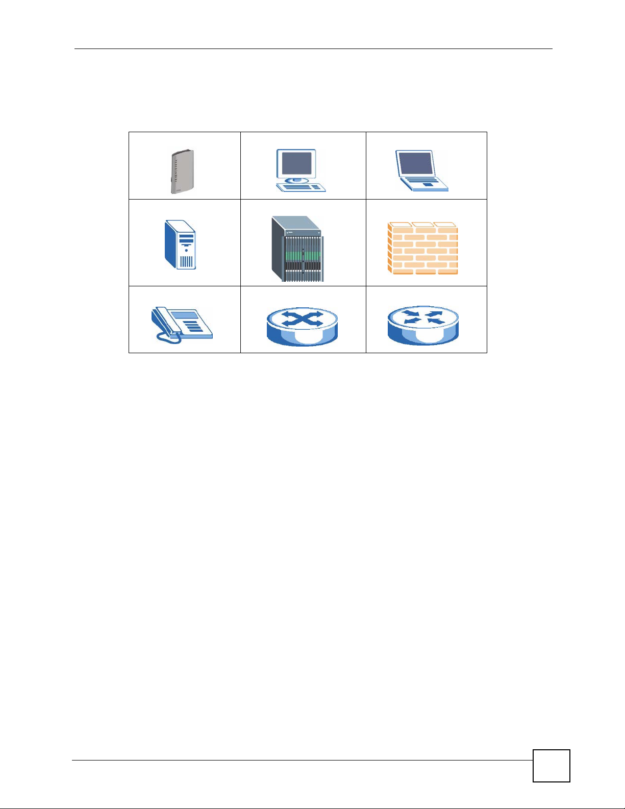
Icons Used in Figures
Figures in this User’s Guide may use the following generic icons. The ZyXEL Device icon is
not an exact representation of your device.
ZyXEL Device Computer Notebook computer
Server DSLAM Firewall
Telephone Switch Router
P-2304R-P1 Series User’s Guide
5
Page 6

Safety Warnings
Safety Warnings
1 For your safety, be sure to read and follow all warning notices and instructions.
• Do NOT use this product near water, for example, in a wet basement or near a swimming
pool.
• Do NOT expose your device to dampness, dust or corrosive liquids.
• Do NOT store things on the device.
• Do NOT install, use, or service this device during a thunderstorm. There is a remote risk
of electric shock from lightning.
• Connect ONLY suitable accessories to the device.
• Do NOT open the device or unit. Opening or removing covers can expose you to
dangerous high voltage points or other risks. ONLY qualified service personnel should
service or disassemble this device. Please contact your vendor for further information.
• Make sure to connect the cables to the correct ports.
• Place connecting cables carefully so that no one will step on them or stumble over them.
• Always disconnect all cables from this device before servicing or disassembling.
• Use ONLY an appropriate power adaptor or cord for your device.
• Connect the power adaptor or cord to the right supply voltage (for example, 110V AC in
North America or 230V AC in Europe).
• Do NOT allow anything to rest on the power adaptor or cord and do NOT place the
product where anyone can walk on the power adaptor or cord.
• Do NOT use the device if the power adaptor or cord is damaged as it might cause
electrocution.
• If the power adaptor or cord is damaged, remove it from the power outlet.
• Do NOT attempt to repair the power adaptor or cord. Contact your local vendor to order a
new one.
• Do not use the device outside, and make sure all the connections are indoors. There is a
remote risk of electric shock from lightning.
• Use only No. 26 AWG (American Wire Gauge) or larger telecommunication line cord.
6
This product is recyclable. Dispose of it properly.
P-2304R-P1 Series User’s Guide
Page 7

Contents Overview
Contents Overview
Introduction and Wizard ........................................................................................................25
Introducing the ZyXEL Device ...................................................................................................27
Introducing the Web Configurator .............................................................................................. 33
Status Screens .......................................................................................................................... 41
Wizard Setup ............................................................................................................................. 51
Bridge Mode .............................................................................................................................. 71
Network ................................................................................................................................... 73
WAN .......................................................................................................................................... 75
LAN ............................................................................................................................................ 85
NAT ............................................................................................................................................ 97
VoIP ....................................................................................................................................... 105
SIP ........................................................................................................................................... 107
Phone ...................................................................................................................................... 121
Phone Book ............................................................................................................................. 129
Security and Management .................................................................................................. 135
Firewall .................................................................................................................................... 137
Content Filter ........................................................................................................................... 145
Static Route ............................................................................................................................. 149
Bandwidth MGMT .................................................................................................................... 153
Remote MGMT ........................................................................................................................ 165
Maintenance and Troubleshooting ..................................................................................... 173
UPnP ....................................................................................................................................... 175
System ..................................................................................................................................... 187
Logs ......................................................................................................................................... 195
Tools ........................................................................................................................................ 209
Troubleshooting ....................................................................................................................... 215
Appendices and Index ......................................................................................................... 221
P-2304R-P1 Series User’s Guide
7
Page 8

Contents Overview
8
P-2304R-P1 Series User’s Guide
Page 9

Table of Contents
Table of Contents
About This User's Guide ..........................................................................................................3
Document Conventions............................................................................................................4
Safety Warnings........................................................................................................................6
Contents Overview ...................................................................................................................7
Table of Contents...................................................................................................................... 9
List of Figures ......................................................................................................................... 17
List of Tables...........................................................................................................................21
Part I: Introduction and Wizard............................................................. 25
Chapter 1
Introducing the ZyXEL Device...............................................................................................27
1.1 VoIP Station Gateway Overview .......................................................................................... 27
1.2 Ways to Manage the ZyXEL Device .................................................................................... 27
1.3 Good Habits for Managing the ZyXEL Device ..................................................................... 27
1.4 LEDs .................................................................................................................................... 28
1.5 Applications ......................................................................................................................... 29
1.5.1 Make Calls via VoIP Service Provider ........................................................................ 29
1.5.2 Make Calls via IP-PBX ............................................................................................... 30
1.5.3 Make Peer-to-peer Calls ............................................................................................ 31
Chapter 2
Introducing the Web Configurator ........................................................................................ 33
2.1 Web Configurator Overview ................................................................................................. 33
2.2 Accessing the Web Configurator ......................................................................................... 33
2.3 Resetting the ZyXEL Device ................................................................................................ 35
2.4 Web Configurator Main Screen ........................................................................................... 36
2.4.1 Title Bar ...................................................................................................................... 37
2.4.2 Navigation Panel ........................................................................................................ 37
2.4.3 Main Window ..............................................................................................................39
2.4.4 Status Bar ................................................................................................................... 39
Chapter 3
Status Screens........................................................................................................................ 41
P-2304R-P1 Series User’s Guide
9
Page 10

Table of Contents
3.1 Status Screen ...................................................................................................................... 41
3.2 Any IP Table ....................................................................................................................... 44
3.3 DHCP Table ........................................................................................................................ 45
3.4 VoIP Statistics ..................................................................................................................... 46
3.5 BW MGMT Monitor ............................................................................................................. 47
3.6 Packet Statistics .................................................................................................................. 49
Chapter 4
Wizard Setup ........................................................................................................................... 51
4.1 Main Wizard Screen ............................................................................................................ 51
4.2 Connection Wizard .............................................................................................................. 52
4.2.1 Welcome .................................................................................................................... 53
4.2.2 System Information .................................................................................................... 53
4.2.3 ISP Parameters .......................................................................................................... 54
4.2.4 Your IP Address ......................................................................................................... 57
4.2.5 WAN IP Address Assignment ..................................................................................... 57
4.2.6 MAC Address ............................................................................................................. 60
4.2.7 Finish .......................................................................................................................... 61
4.3 VoIP Setup Wizard .............................................................................................................. 62
4.3.1 SIP Settings ............................................................................................................... 62
4.3.2 Registration Complete ................................................................................................ 63
4.4 Bandwidth Management Wizard .......................................................................................... 65
4.4.1 Welcome .................................................................................................................... 66
4.4.2 General Information ................................................................................................... 67
4.4.3 Services Setup ...........................................................................................................68
4.4.4 Priority Setup .............................................................................................................. 69
4.4.5 Finish .......................................................................................................................... 70
Chapter 5
Bridge Mode ............................................................................................................................ 71
5.1 Bridge Mode Overview ........................................................................................................ 71
5.2 Bridge Mode Procedure ....................................................................................................... 72
Part II: Network....................................................................................... 73
Chapter 6
WAN..........................................................................................................................................75
6.1 WAN Overview .................................................................................................................... 75
6.1.1 PPPoE Encapsulation ................................................................................................ 75
6.1.2 WAN IP Address Assignment ..................................................................................... 75
6.1.3 MAC Address ............................................................................................................. 76
10
P-2304R-P1 Series User’s Guide
Page 11

Table of Contents
6.1.4 RIP Setup ................................................................................................................... 76
6.1.5 DNS Server Address Assignment .............................................................................. 76
6.2 WAN Internet Connection Screen ....................................................................................... 77
6.2.1 Ethernet ...................................................................................................................... 77
6.2.2 Roadrunner ................................................................................................................ 78
6.2.3 PPPoE ........................................................................................................................ 79
6.3 WAN Advanced Screen ....................................................................................................... 81
6.4 WAN Traffic Redirect Screen ............................................................................................... 83
Chapter 7
LAN........................................................................................................................................... 85
7.1 LAN Overview ...................................................................................................................... 85
7.1.1 IP Address and Subnet Mask ..................................................................................... 85
7.1.2 DHCP Setup ...............................................................................................................86
7.1.3 LAN TCP/IP ................................................................................................................ 86
7.1.4 DNS Server Address .................................................................................................. 86
7.1.5 RIP Setup ................................................................................................................... 87
7.1.6 Multicast ..................................................................................................................... 87
7.1.7 Any IP ......................................................................................................................... 88
7.2 LAN Screens ....................................................................................................................... 89
7.2.1 LAN IP Screen ........................................................................................................... 89
7.2.2 LAN DHCP Setup Screen .......................................................................................... 90
7.2.3 LAN Static DHCP Screen ........................................................................................... 91
7.2.4 LAN Client List Screen ............................................................................................... 92
7.2.5 LAN IP Alias Screen ................................................................................................... 93
7.2.6 LAN Advanced Screen ............................................................................................... 95
Chapter 8
NAT........................................................................................................................................... 97
8.1 NAT Overview ...................................................................................................................... 97
8.1.1 Port Forwarding: Services and Port Numbers ............................................................ 97
8.1.2 Trigger Port Forwarding ............................................................................................. 98
8.1.3 SIP ALG ..................................................................................................................... 99
8.2 NAT Screens ........................................................................................................................ 99
8.2.1 NAT General Screen .................................................................................................. 99
8.2.2 NAT Port Forwarding Screen ................................................................................... 100
8.2.3 NAT Port Forwarding Edit Screen ............................................................................ 102
8.2.4 NAT Trigger Port Screen .......................................................................................... 102
8.2.5 NAT ALG Screen ...................................................................................................... 104
Part III: VoIP .......................................................................................... 105
P-2304R-P1 Series User’s Guide
11
Page 12

Table of Contents
Chapter 9
SIP .......................................................................................................................................... 107
9.1 SIP Overview ..................................................................................................................... 107
9.1.1 Introduction to VoIP .................................................................................................. 107
9.1.2 Introduction to SIP .................................................................................................... 107
9.1.3 SIP Identities ............................................................................................................ 107
9.1.4 SIP Call Progression ................................................................................................ 108
9.1.5 SIP Client Server ...................................................................................................... 108
9.1.6 RTP ...........................................................................................................................110
9.1.7 NAT and SIP .............................................................................................................110
9.1.8 Voice Coding .............................................................................................................111
9.1.9 PSTN Call Setup Signaling .......................................................................................112
9.1.10 MWI (Message Waiting Indication) ..........................................................................112
9.1.11 Quality of Service (QoS) ..........................................................................................112
9.2 SIP Screens ........................................................................................................................113
9.2.1 SIP Settings Screen ..................................................................................................113
9.2.2 Advanced SIP Setup Screen .....................................................................................115
9.2.3 SIP QoS Screen ........................................................................................................119
Chapter 10
Phone..................................................................................................................................... 121
10.1 Phone Overview .............................................................................................................. 121
10.1.1 Voice Activity Detection/Silence Suppression/Comfort Noise ................................ 121
10.1.2 Echo Cancellation .................................................................................................. 121
10.1.3 Supplementary Phone Services Overview ............................................................. 121
10.2 Phone Screens ................................................................................................................ 124
10.2.1 Analog Phone Screen ............................................................................................ 124
10.2.2 Advanced Analog Phone Setup Screen ................................................................. 125
10.2.3 Common Phone Settings Screen ........................................................................... 126
10.2.4 Phone Region Screen ............................................................................................ 127
Chapter 11
Phone Book........................................................................................................................... 129
11.1 Phone Book Overview ..................................................................................................... 129
11.2 Phone Book Screens ....................................................................................................... 129
11.2.1 Incoming Call Policy Screen ................................................................................... 129
11.2.2 Speed Dial Screen .................................................................................................. 131
Part IV: Security and Management ..................................................... 135
Chapter 12
Firewall................................................................................................................................... 137
12
P-2304R-P1 Series User’s Guide
Page 13

Table of Contents
12.1 Firewall Overview ............................................................................................................ 137
12.1.1 Stateful Inspection Firewall. ................................................................................... 137
12.1.2 About the ZyXEL Device Firewall ........................................................................... 137
12.1.3 Guidelines For Enhancing Security With Your Firewall .......................................... 138
12.1.4 The Firewall, NAT and Remote Management ........................................................ 138
12.2 Triangle Route ................................................................................................................. 139
12.2.1 The “Triangle Route” Problem ................................................................................ 139
12.2.2 Solving the “Triangle Route” Problem .................................................................... 140
12.3 Firewall Screens .............................................................................................................. 141
12.3.1 General Firewall Screen ......................................................................................... 141
12.3.2 Firewall Services Screen ........................................................................................ 142
Chapter 13
Content Filter......................................................................................................................... 145
13.1 Content Filtering Overview .............................................................................................. 145
13.2 Content Filtering Screens ................................................................................................ 145
13.2.1 Content Filter Screen ............................................................................................. 145
13.2.2 Content Filter Schedule Screen ............................................................................. 147
Chapter 14
Static Route ........................................................................................................................... 149
14.1 Static Route Overview .....................................................................................................149
14.2 Static Route Screens ....................................................................................................... 149
14.2.1 IP Static Route Screen ........................................................................................... 149
14.2.2 IP Static Route Edit Screen .................................................................................... 150
Chapter 15
Bandwidth MGMT..................................................................................................................153
15.1 Bandwidth Management Overview .................................................................................. 153
15.1.1 Bandwidth Classes and Filters ............................................................................... 153
15.1.2 Proportional Bandwidth Allocation ......................................................................... 154
15.1.3 Application-based Bandwidth Management ........................................................... 154
15.1.4 Subnet-based Bandwidth Management ................................................................. 154
15.1.5 Application- and Subnet-based Bandwidth Management ...................................... 154
15.1.6 Scheduler ...............................................................................................................154
15.1.7 Maximize Bandwidth Usage ................................................................................... 155
15.1.8 Bandwidth Borrowing ............................................................................................. 157
15.1.9 Over Allotment of Bandwidth .................................................................................. 158
15.2 Bandwidth Management Screens .................................................................................... 158
15.2.1 Bandwidth Management Summary Screen ............................................................ 158
15.2.2 Bandwidth Class Setup Screen .............................................................................. 160
15.2.3 Bandwidth Class Edit Screen ................................................................................. 161
15.2.4 Bandwidth Monitor Screen ..................................................................................... 163
P-2304R-P1 Series User’s Guide
13
Page 14

Table of Contents
Chapter 16
Remote MGMT.......................................................................................................................165
16.1 Remote Management Overview ...................................................................................... 165
16.1.1 Remote Management Limitations .......................................................................... 165
16.1.2 Remote Management and NAT .............................................................................. 165
16.2 SNMP .............................................................................................................................. 166
16.2.1 Supported MIBs ..................................................................................................... 167
16.2.2 SNMP Traps ........................................................................................................... 167
16.2.3 System Timeout ..................................................................................................... 167
16.3 Remote Management Screens ........................................................................................ 168
16.3.1 WWW Screen ......................................................................................................... 168
16.3.2 Telnet Screen ......................................................................................................... 168
16.3.3 FTP Screen ............................................................................................................ 169
16.3.4 SNMP Screen ....................................................................................................... 170
16.3.5 DNS Screen ........................................................................................................... 171
16.3.6 Security Screen ...................................................................................................... 171
Part V: Maintenance and Troubleshooting ........................................ 173
Chapter 17
UPnP ......................................................................................................................................175
17.1 Introducing Universal Plug and Play ................................................................................ 175
17.1.1 How do I know if I'm using UPnP? ......................................................................... 175
17.1.2 NAT Traversal ........................................................................................................ 175
17.1.3 Cautions with UPnP ............................................................................................... 175
17.1.4 UPnP and ZyXEL ................................................................................................... 176
17.2 UPnP Examples .............................................................................................................. 176
17.2.1 Installing UPnP in Windows Example .................................................................... 176
17.2.2 Using UPnP in Windows XP Example ................................................................... 179
17.3 UPnP Screen ................................................................................................................... 185
Chapter 18
System ................................................................................................................................... 187
18.1 System Features Overview ............................................................................................. 187
18.1.1 System Name ......................................................................................................... 187
18.1.2 Domain Name ........................................................................................................ 187
18.1.3 DNS Server Address Assignment .......................................................................... 187
18.1.4 Dynamic DNS ......................................................................................................... 188
18.1.5 Pre-defined NTP Time Servers List ........................................................................ 188
18.1.6 Resetting the Time ................................................................................................. 189
18.2 System Screens .............................................................................................................. 189
14
P-2304R-P1 Series User’s Guide
Page 15

Table of Contents
18.2.1 General System Screen ......................................................................................... 189
18.2.2 Dynamic DNS Screen ............................................................................................ 190
18.2.3 Time Setting Screen ............................................................................................... 192
Chapter 19
Logs .......................................................................................................................................195
19.1 Logs Overview ................................................................................................................. 195
19.1.1 Alerts ...................................................................................................................... 195
19.1.2 Syslog Logs ............................................................................................................ 196
19.2 Logs Screens ................................................................................................................... 197
19.2.1 Log Viewer Screen ................................................................................................. 197
19.2.2 Log Settings Screen ............................................................................................... 198
19.3 Log Message Descriptions .............................................................................................. 200
Chapter 20
Tools.......................................................................................................................................209
20.1 Tools Overview ................................................................................................................ 209
20.1.1 ZyXEL Firmware .................................................................................................... 209
20.2 Tools Screens .................................................................................................................. 209
20.2.1 Firmware Screen .................................................................................................... 209
20.2.2 Firmware Upload Screens ...................................................................................... 210
20.2.3 Configuration Screen ..............................................................................................211
20.2.4 Restore Configuration Screens .............................................................................. 212
20.2.5 Restart Screen ....................................................................................................... 213
Chapter 21
Troubleshooting.................................................................................................................... 215
21.1 Power, Hardware Connections, and LEDs ...................................................................... 215
21.2 ZyXEL Device Access and Login .................................................................................... 216
21.3 Internet Access ................................................................................................................ 217
21.4 Phone Calls and VoIP ......................................................................................................219
Part VI: Appendices and Index ........................................................... 221
Appendix A Product Specifications.......................................................................................223
Appendix B Pop-up Windows, JavaScripts and Java Permissions ...................................... 229
Appendix C Setting up Your Computer’s IP Address ...........................................................235
Appendix D IP Addresses and Subnetting ........................................................................... 249
Appendix E SIP Passthrough ...............................................................................................257
P-2304R-P1 Series User’s Guide
15
Page 16

Table of Contents
Appendix F NAT ...................................................................................................................259
Appendix G Internal SPTGEN ..............................................................................................267
Appendix H Services ............................................................................................................283
Appendix I Legal Information................................................................................................ 287
Appendix J Customer Support .............................................................................................291
Index....................................................................................................................................... 295
16
P-2304R-P1 Series User’s Guide
Page 17

List of Figures
List of Figures
Figure 1 LEDs ......................................................................................................................................... 28
Figure 2 VoIP Service Provider Application ............................................................................................ 30
Figure 3 IP-PBX Application ................................................................................................................... 30
Figure 4 Peer-to-peer Calling ................................................................................................................. 31
Figure 5 Login Screen ............................................................................................................................ 34
Figure 6 Change Password Screen ........................................................................................................ 34
Figure 7 Select Mode Screen ................................................................................................................. 35
Figure 8 Main Screen ............................................................................................................................. 36
Figure 9 Status Screen ........................................................................................................................... 42
Figure 10 Any IP Table ........................................................................................................................... 45
Figure 11 DHCP Table ............................................................................................................................ 45
Figure 12 VoIP Statistics ......................................................................................................................... 46
Figure 13 BW MGMT Monitor ................................................................................................................. 48
Figure 14 Packet Statistics ..................................................................................................................... 49
Figure 15 Main Wizard Screen ............................................................................................................... 51
Figure 16 Connection Wizard > Welcome .............................................................................................. 53
Figure 17 Connection Wizard > System Information .............................................................................. 54
Figure 18 Connection Wizard > ISP Parameters (Ethernet) ................................................................... 55
Figure 19 Connection Wizard > ISP Parameters (PPPoE) ..................................................................... 56
Figure 20 Connection Wizard > IP Address ........................................................................................... 57
Figure 21 Connection Wizard > IP Address (Ethernet) .......................................................................... 58
Figure 22 Connection Wizard > IP Address (PPPoE) ............................................................................ 59
Figure 23 Connection Wizard > MAC Address ....................................................................................... 60
Figure 24 Connection Wizard > Finish ................................................................................................... 61
Figure 25 VoIP Setup Wizard > SIP Settings ......................................................................................... 62
Figure 26 VoIP Setup Wizard > Registration Test .................................................................................. 63
Figure 27 VoIP Setup Wizard > Registration Complete (Success) ......................................................... 64
Figure 28 VoIP Setup Wizard > Registration Complete (Fail) ................................................................ 65
Figure 29 Bandwidth Management Wizard > Welcome ......................................................................... 66
Figure 30 Bandwidth Management Wizard > General Information ......................................................... 67
Figure 31 Bandwidth Management Wizard > Services Setup ................................................................ 68
Figure 32 Bandwidth Management Wizard > Priority Setup ................................................................... 69
Figure 33 Bandwidth Management Wizard > Finish ............................................................................... 70
Figure 34 Prompt Before Change to Router Mode ................................................................................. 72
Figure 35 Network > WAN > Internet Connection (Ethernet) ................................................................. 77
Figure 36 Network > WAN > Internet Connection (Roadrunner) ............................................................ 78
Figure 37 Network > WAN > Internet Connection (PPPoE) ................................................................... 80
Figure 38 Network > WAN > Advanced .................................................................................................. 82
P-2304R-P1 Series User’s Guide
17
Page 18

List of Figures
Figure 39 Network > WAN > Traffic Redirect .......................................................................................... 83
Figure 40 Any IP Example ...................................................................................................................... 88
Figure 41 Network > LAN > IP ................................................................................................................ 89
Figure 42 Network > LAN > DHCP Setup .............................................................................................. 90
Figure 43 Network > LAN > Static DHCP ............................................................................................... 92
Figure 44 Network > LAN > Client List ................................................................................................... 93
Figure 45 Network > LAN > IP Alias ....................................................................................................... 94
Figure 46 Network > LAN > Advanced ................................................................................................... 95
Figure 47 Multiple Servers Behind NAT Example ..................................................................................98
Figure 48 Trigger Port Forwarding Process: Example ............................................................................ 98
Figure 49 Network > NAT > General ...................................................................................................... 99
Figure 50 Network > NAT > Port Forwarding ....................................................................................... 101
Figure 51 Network > NAT > Port Forwarding > Edit ............................................................................. 102
Figure 52 Network > NAT > Trigger Port .............................................................................................. 103
Figure 53 Network > NAT > ALG .......................................................................................................... 104
Figure 54 SIP User Agent ..................................................................................................................... 109
Figure 55 SIP Proxy Server .................................................................................................................. 109
Figure 56 SIP Redirect Server ...............................................................................................................110
Figure 57 STUN ..................................................................................................................................... 111
Figure 58 DiffServ: Differentiated Service Field .....................................................................................113
Figure 59 VoIP > SIP > SIP Settings .....................................................................................................114
Figure 60 VoIP > SIP > SIP Settings > Advanced .................................................................................116
Figure 61 VoIP > SIP > QoS ..................................................................................................................119
Figure 62 VoIP > Phone > Analog Phone ............................................................................................. 125
Figure 63 VoIP > Phone > Analog Phone > Advanced ........................................................................ 126
Figure 64 VoIP > Phone > Common ..................................................................................................... 127
Figure 65 VoIP > Phone > Region ........................................................................................................ 127
Figure 66 VoIP > Phone Book > Incoming Call Policy .......................................................................... 130
Figure 67 VoIP > Phone Book > Speed Dial ......................................................................................... 132
Figure 68 Firewall Rule Directions ........................................................................................................ 138
Figure 69 Ideal Firewall Setup .............................................................................................................. 139
Figure 70 “Triangle Route” Problem ..................................................................................................... 140
Figure 71 IP Alias ................................................................................................................................. 141
Figure 72 Security > Firewall > General ............................................................................................... 141
Figure 73 Security > Firewall > Services .............................................................................................. 142
Figure 74 Security > Content Filter > Filter ........................................................................................... 146
Figure 75 Security > Content Filter > Schedule .................................................................................... 147
Figure 76 Example of Static Routing Topology ..................................................................................... 149
Figure 77 Management > Static Route > IP Static Route ..................................................................... 150
Figure 78 Management > Static Route > IP Static Route > Edit ........................................................... 151
Figure 79 Subnet-based Bandwidth Management Example ................................................................ 154
Figure 80 Management > Bandwidth MGMT > Summary .................................................................... 159
Figure 81 Management > Bandwidth MGMT > Class Setup ................................................................ 160
18
P-2304R-P1 Series User’s Guide
Page 19

List of Figures
Figure 82 Management > Bandwidth MGMT > Class Setup > Edit ...................................................... 162
Figure 83 Management > Bandwidth MGMT > Monitor ....................................................................... 163
Figure 84 SNMP Management Model .................................................................................................. 166
Figure 85 Management > Remote MGMT > WWW ............................................................................. 168
Figure 86 Management > Remote MGMT > Telnet .............................................................................. 168
Figure 87 Management > Remote MGMT > FTP ................................................................................. 169
Figure 88 Management > Remote MGMT > SNMP ............................................................................. 170
Figure 89 Management > Remote MGMT > DNS ................................................................................ 171
Figure 90 Management > Remote MGMT > Security ........................................................................... 171
Figure 91 Add/Remove Programs: Windows Setup: Communication .................................................. 176
Figure 92 Add/Remove Programs: Windows Setup: Communication: Components ............................ 177
Figure 93 Network Connections ........................................................................................................... 177
Figure 94 Windows Optional Networking Components Wizard ............................................................ 178
Figure 95 Networking Services ............................................................................................................. 178
Figure 96 Network Connections ........................................................................................................... 179
Figure 97 Internet Connection Properties ............................................................................................ 180
Figure 98 Internet Connection Properties: Advanced Settings ............................................................. 181
Figure 99 Internet Connection Properties: Advanced Settings: Add .................................................... 181
Figure 100 System Tray Icon ................................................................................................................ 182
Figure 101 Internet Connection Status ................................................................................................. 182
Figure 102 Network Connections ......................................................................................................... 183
Figure 103 Network Connections: My Network Places ........................................................................ 184
Figure 104 Network Connections: My Network Places: Properties: Example ...................................... 184
Figure 105 Management > UPnP ......................................................................................................... 185
Figure 106 Maintenance > System > General ......................................................................................189
Figure 107 Maintenance > System > Dynamic DNS ............................................................................ 191
Figure 108 Maintenance > System > Time Setting ............................................................................... 192
Figure 109 Maintenance > Logs > View Log ........................................................................................ 197
Figure 110 Maintenance > Logs > Log Settings ...................................................................................198
Figure 111 Maintenance > Tools > Firmware ........................................................................................ 210
Figure 112 Firmware Upload In Process .............................................................................................. 210
Figure 113 Network Temporarily Disconnected .....................................................................................211
Figure 114 Firmware Upload Error ........................................................................................................211
Figure 115 Maintenance > Tools > Configuration ..................................................................................211
Figure 116 Configuration Upload Successful ....................................................................................... 212
Figure 117 Network Temporarily Disconnected ....................................................................................213
Figure 118 Configuration Upload Error ................................................................................................. 213
Figure 119 Maintenance > Tools > Restart ........................................................................................... 213
Figure 120 Maintenance > Tools > Restart > In Progress .................................................................... 214
Figure 121 Pop-up Blocker ................................................................................................................... 229
Figure 122 Internet Options ................................................................................................................. 230
Figure 123 Internet Options .................................................................................................................. 231
Figure 124 Pop-up Blocker Settings ..................................................................................................... 231
P-2304R-P1 Series User’s Guide
19
Page 20

List of Figures
Figure 125 Internet Options .................................................................................................................. 232
Figure 126 Security Settings - Java Scripting ....................................................................................... 233
Figure 127 Security Settings - Java ...................................................................................................... 233
Figure 128 Java (Sun) .......................................................................................................................... 234
Figure 129 WIndows 95/98/Me: Network: Configuration ...................................................................... 236
Figure 130 Windows 95/98/Me: TCP/IP Properties: IP Address .......................................................... 237
Figure 131 Windows 95/98/Me: TCP/IP Properties: DNS Configuration .............................................. 238
Figure 132 Windows XP: Start Menu .................................................................................................... 239
Figure 133 Windows XP: Control Panel ............................................................................................... 239
Figure 134 Windows XP: Control Panel: Network Connections: Properties ......................................... 240
Figure 135 Windows XP: Local Area Connection Properties ............................................................... 240
Figure 136 Windows XP: Internet Protocol (TCP/IP) Properties .......................................................... 241
Figure 137 Windows XP: Advanced TCP/IP Properties ....................................................................... 242
Figure 138 Windows XP: Internet Protocol (TCP/IP) Properties .......................................................... 243
Figure 139 Macintosh OS X: Apple Menu ............................................................................................ 244
Figure 140 Macintosh OS X: Network .................................................................................................. 244
Figure 141 Red Hat 9.0: KDE: Network Configuration: Devices ......................................................... 245
Figure 142 Red Hat 9.0: KDE: Ethernet Device: General ................................................................... 246
Figure 143 Red Hat 9.0: KDE: Network Configuration: DNS ............................................................... 246
Figure 144 Red Hat 9.0: KDE: Network Configuration: Activate ......................................................... 247
Figure 145 Red Hat 9.0: Dynamic IP Address Setting in ifconfig-eth0 ................................................ 247
Figure 146 Red Hat 9.0: Static IP Address Setting in ifconfig-eth0 ................................................... 247
Figure 147 Red Hat 9.0: DNS Settings in resolv.conf ........................................................................ 248
Figure 148 Red Hat 9.0: Restart Ethernet Card .................................................................................. 248
Figure 149 Red Hat 9.0: Checking TCP/IP Properties ........................................................................ 248
Figure 150 Network Number and Host ID ............................................................................................ 250
Figure 151 Subnetting Example: Before Subnetting ............................................................................ 252
Figure 152 Subnetting Example: After Subnetting ............................................................................... 253
Figure 153 How NAT Works ................................................................................................................. 260
Figure 154 NAT Application With IP Alias ............................................................................................ 261
Figure 155 Full Cone NAT Example ..................................................................................................... 263
Figure 156 Restricted Cone NAT Example ........................................................................................... 264
Figure 157 Port Restricted Cone NAT Example ................................................................................... 265
Figure 158 Symmetric NAT .................................................................................................................. 265
Figure 159 Configuration Text File Format: Column Descriptions ........................................................ 267
Figure 160 Invalid Parameter Entered: Command Line Example ........................................................ 268
Figure 161 Valid Parameter Entered: Command Line Example ........................................................... 268
Figure 162 Internal SPTGEN FTP Download Example ........................................................................ 269
Figure 163 Internal SPTGEN FTP Upload Example ............................................................................ 269
20
P-2304R-P1 Series User’s Guide
Page 21

List of Tables
List of Tables
Table 1 LED Descriptions ...................................................................................................................... 28
Table 2 Web Configurator Icons in the Title Bar .................................................................................... 37
Table 3 Navigation Panel Summary ...................................................................................................... 37
Table 4 Status Screen ............................................................................................................................ 42
Table 5 Any IP Table .............................................................................................................................. 45
Table 6 DHCP Table .............................................................................................................................. 45
Table 7 VoIP Statistics ........................................................................................................................... 46
Table 8 BW MGMT Monitor ................................................................................................................... 48
Table 9 Packet Statistics Window .......................................................................................................... 50
Table 10 Main Wizard Screen ................................................................................................................ 52
Table 11 Connection Wizard > Welcome ............................................................................................... 53
Table 12 Connection Wizard > System Information ...............................................................................54
Table 13 Connection Wizard > ISP Parameters (Ethernet) ................................................................... 55
Table 14 Connection Wizard > ISP Parameters (PPPoE) ..................................................................... 56
Table 15 Connection Wizard > IP Address ............................................................................................ 57
Table 16 Connection Wizard > IP Address (Ethernet) ........................................................................... 58
Table 17 Connection Wizard > IP Address (PPPoE) ............................................................................. 60
Table 18 Connection Wizard > MAC Address ....................................................................................... 61
Table 19 Connection Wizard > Finish .................................................................................................... 62
Table 20 VoIP Setup Wizard > SIP Settings .......................................................................................... 63
Table 21 VoIP Setup Wizard > Registration Complete (Success) ......................................................... 64
Table 22 VoIP Setup Wizard > Registration Complete (Fail) ................................................................. 65
Table 23 Bandwidth Management Wizard > Welcome .......................................................................... 66
Table 24 Bandwidth Management Wizard > General Information ......................................................... 67
Table 25 Bandwidth Management Wizard > Services Setup ................................................................. 68
Table 26 Bandwidth Management Wizard > Priority Setup ................................................................... 69
Table 27 Bandwidth Management Wizard > Finish ............................................................................... 70
Table 28 Bridge Mode: Features by Screen .......................................................................................... 71
Table 29 Private IP Address Ranges ..................................................................................................... 75
Table 30 Network > WAN > Internet Connection (Ethernet) .................................................................. 77
Table 31 Network > WAN > Internet Connection (Roadrunner) ............................................................. 79
Table 32 Network > WAN > Internet Connection (PPPoE) .................................................................... 80
Table 33 Network > WAN > Advanced .................................................................................................. 82
Table 34 Network > WAN > Traffic Redirect .......................................................................................... 84
Table 35 Network > LAN > IP ................................................................................................................ 90
Table 36 Network > LAN > DHCP Setup ............................................................................................... 90
Table 37 Network > LAN > Static DHCP ................................................................................................ 92
Table 38 Network > LAN > Client List .................................................................................................... 93
P-2304R-P1 Series User’s Guide
21
Page 22

List of Tables
Table 39 Network > LAN > IP Alias ....................................................................................................... 94
Table 40 Network > LAN > Advanced .................................................................................................... 95
Table 41 Network > NAT > General ..................................................................................................... 100
Table 42 Network > NAT > Port Forwarding ........................................................................................ 101
Table 43 Network > NAT > Port Forwarding > Edit .............................................................................. 102
Table 44 Network > NAT > Trigger Port ............................................................................................... 103
Table 45 Network > NAT > ALG .......................................................................................................... 104
Table 46 SIP Call Progression ............................................................................................................. 108
Table 47 VoIP > SIP > SIP Settings ......................................................................................................114
Table 48 VoIP > SIP > SIP Settings > Advanced .................................................................................117
Table 49 VoIP > SIP > QoS ................................................................................................................. 120
Table 50 European Type Flash Key Commands ................................................................................. 122
Table 51 USA Type Flash Key Commands ......................................................................................... 123
Table 52 VoIP > Phone > Analog Phone ............................................................................................. 125
Table 53 VoIP > Phone > Analog Phone > Advanced ......................................................................... 126
Table 54 VoIP > Phone > Common ..................................................................................................... 127
Table 55 VoIP > Phone > Region ........................................................................................................ 127
Table 56 VoIP > Phone Book > Incoming Call Policy .......................................................................... 130
Table 57 VoIP > Phone Book > Speed Dial ......................................................................................... 132
Table 58 Security > Firewall > General ................................................................................................ 141
Table 59 Security > Firewall > Services ............................................................................................... 142
Table 60 Security > Content Filter > Filter ........................................................................................... 146
Table 61 Security > Content Filter > Schedule .................................................................................... 147
Table 62 Management > Static Route > IP Static Route ...................................................................... 150
Table 63 Management > Static Route > IP Static Route > Edit ........................................................... 151
Table 64 Application and Subnet-based Bandwidth Management Example ....................................... 154
Table 65 Maximize Bandwidth Usage Example ................................................................................... 155
Table 66 Priority-based Allotment of Unused and Unbudgeted Bandwidth Example .......................... 156
Table 67 Fairness-based Allotment of Unused and Unbudgeted Bandwidth Example ....................... 156
Table 68 Bandwidth Borrowing Example ............................................................................................. 157
Table 69 Over Allotment of Bandwidth Example ................................................................................. 158
Table 70 Management > Bandwidth MGMT > Summary ..................................................................... 159
Table 71 Management > Bandwidth MGMT > Class Setup ................................................................. 161
Table 72 Management > Bandwidth MGMT > Class Setup > Edit ...................................................... 162
Table 73 Management > Bandwidth MGMT > Monitor ........................................................................ 164
Table 74 SNMP Traps .......................................................................................................................... 167
Table 75 Management > Remote MGMT > WWW .............................................................................. 168
Table 76 Management > Remote MGMT > Telnet ............................................................................... 169
Table 77 Management > Remote MGMT > FTP ................................................................................. 169
Table 78 Management > Remote MGMT > SNMP .............................................................................. 170
Table 79 Management > Remote MGMT > DNS ................................................................................. 171
Table 80 Management > Remote MGMT > Security ........................................................................... 172
Table 81 Management > UPnP ............................................................................................................ 185
22
P-2304R-P1 Series User’s Guide
Page 23

List of Tables
Table 82 Pre-defined NTP Time Servers ............................................................................................. 188
Table 83 Maintenance > System > General ........................................................................................ 190
Table 84 Maintenance > System > Dynamic DNS ............................................................................... 191
Table 85 Maintenance > System > Time Setting ................................................................................. 193
Table 86 Syslog Logs .......................................................................................................................... 196
Table 87 RFC-2408 ISAKMP Payload Types ...................................................................................... 196
Table 88 Maintenance > Logs > View Log ........................................................................................... 197
Table 89 Maintenance > Logs > Log Settings ..................................................................................... 198
Table 90 System Error Logs ................................................................................................................ 200
Table 91 System Maintenance Logs .................................................................................................... 200
Table 92 Access Control Logs ............................................................................................................. 201
Table 93 TCP Reset Logs .................................................................................................................... 201
Table 94 Packet Filter Logs ................................................................................................................. 202
Table 95 ICMP Logs ............................................................................................................................ 202
Table 96 CDR Logs ............................................................................................................................. 202
Table 97 PPP Logs .............................................................................................................................. 203
Table 98 UPnP Logs ............................................................................................................................ 203
Table 99 Content Filtering Logs ........................................................................................................... 203
Table 100 Attack Logs ......................................................................................................................... 204
Table 101 Remote Management Logs ................................................................................................. 205
Table 102 ICMP Notes ......................................................................................................................... 205
Table 103 SIP Logs ............................................................................................................................. 206
Table 104 RTP Logs ............................................................................................................................ 207
Table 105 FSM Logs: Caller Side ........................................................................................................ 207
Table 106 FSM Logs: Callee Side ....................................................................................................... 207
Table 107 Lifeline Logs ........................................................................................................................ 207
Table 108 Maintenance > Tools > Firmware ........................................................................................ 210
Table 109 Maintenance > Tools > Configuration .................................................................................212
Table 110 Device Specifications .......................................................................................................... 223
Table 111 Firmware Features .............................................................................................................. 223
Table 112 Feature Specifications ......................................................................................................... 226
Table 113 ZyXEL Device Power Adaptor Specifications ...................................................................... 227
Table 114 Subnet Mask Example ........................................................................................................ 250
Table 115 Subnet Masks ..................................................................................................................... 251
Table 116 Maximum Host Numbers ..................................................................................................... 251
Table 117 Alternative Subnet Mask Notation ....................................................................................... 251
Table 118 Subnet 1 .............................................................................................................................. 253
Table 119 Subnet 2 .............................................................................................................................. 254
Table 120 Subnet 3 .............................................................................................................................. 254
Table 121 Subnet 4 .............................................................................................................................. 254
Table 122 Eight Subnets ...................................................................................................................... 254
Table 123 24-bit Network Number Subnet Planning ............................................................................ 255
Table 124 16-bit Network Number Subnet Planning ............................................................................ 255
P-2304R-P1 Series User’s Guide
23
Page 24

List of Tables
Table 125 NAT Definitions ................................................................................................................... 259
Table 126 NAT Mapping Types ............................................................................................................ 262
Table 127 NAT Types .......................................................................................................................... 263
Table 128 Abbreviations Used in the Example Internal SPTGEN Screens Table ............................... 270
Table 129 Menu 1 General Setup ........................................................................................................ 270
Table 130 Menu 3 ................................................................................................................................ 270
Table 131 Menu 4 Internet Access Setup ............................................................................................ 273
Table 132 Menu 12 .............................................................................................................................. 275
Table 133 Menu 15 SUA Server Setup ................................................................................................ 275
Table 134 Menu 21.1 Filter Set #1 ....................................................................................................... 277
Table 135 Menu 21.1 Filer Set #2 ........................................................................................................ 278
Table 136 Menu 23 System Menus ..................................................................................................... 280
Table 137 Menu 24.11 Remote Management Control ......................................................................... 281
Table 138 Command Examples ........................................................................................................... 282
Table 139 Examples of Services ......................................................................................................... 283
24
P-2304R-P1 Series User’s Guide
Page 25

PART I
Introduction and
Wizard
Introducing the ZyXEL Device (27)
Introducing the Web Configurator (33)
Status Screens (41)
Wizard Setup (51)
Bridge Mode (71)
25
Page 26

26
Page 27

CHAPTER 1
Introducing the ZyXEL Device
This chapter introduces the main features and applications of the ZyXEL Device.
1.1 VoIP Station Gateway Overview
The P-2304R-P1 VoIP (Voice over IP) station gateway lets you use traditional analog
telephones to make telephone calls over the Internet. The ZyXEL Device uses SIP (Session
Initiation Protocol), an internationally recognized standard for implementing VoIP.
You can call any landline or mobile telephone as well as IP telephones. You don’t need to
know if the recipient’s connection type is an IP, cellular or landline based service. Calls
received from IP telephones work exactly as you would expect from the traditional telephone
service.
The NAT and DHCP server features allow you to use an Ethernet hub or switch to set up a
private network and allow multiple computers to share a single Internet connection. The
ZyXEL Device also provides content filtering and a firewall for security.
The ZyXEL Device's web configurator allows easy management and configuration.
See Appendix A on page 223 for a complete list of features.
1.2 Ways to Manage the ZyXEL Device
Use any of the following methods to manage the ZyXEL Device.
• Web Configurator. This is recommended for everyday management of the ZyXEL Device
using a (supported) web browser.
• Command Line Interface. Line commands are mostly used for troubleshooting by service
engineers.
• FTP for firmware upgrades and configuration backup/restore.
• SNMP. The device can be monitored by an SNMP manager. See the SNMP chapter in this
User’s Guide.
1.3 Good Habits for Managing the ZyXEL Device
Do the following things regularly to make the ZyXEL Device more secure and to manage the
ZyXEL Device more effectively.
P-2304R-P1 Series User’s Guide
27
Page 28
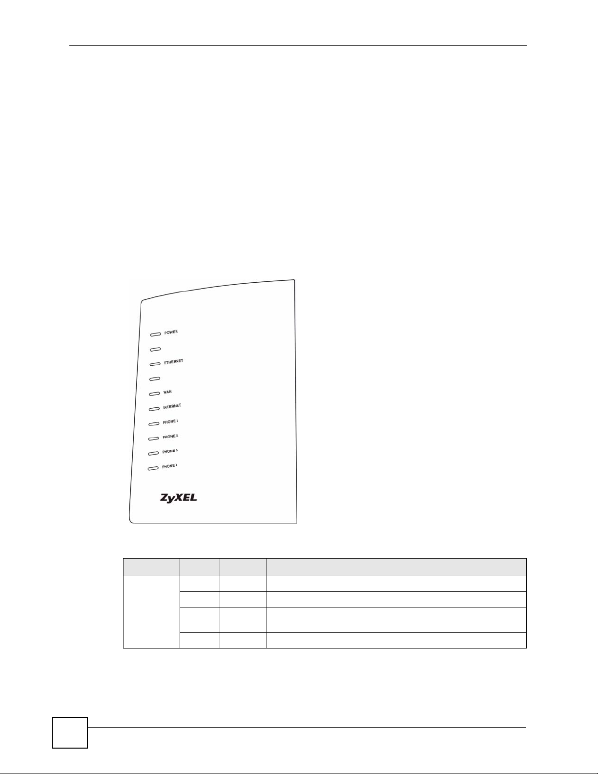
Chapter 1 Introducing the ZyXEL Device
• Change the password. Use a password that’s not easy to guess and that consists of
different types of characters, such as numbers and letters.
• Write down the password and put it in a safe place.
• Back up the configuration (and make sure you know how to restore it). Restoring an
earlier working configuration may be useful if the device becomes unstable or even
crashes. If you forget your password, you will have to reset the ZyXEL Device to its
factory default settings. If you backed up an earlier configuration file, you would not have
to totally re-configure the ZyXEL Device. You could simply restore your last
configuration.
1.4 LEDs
The following graphic displays the labels of the LEDs.
Figure 1 LEDs
28
None of the LEDs are on if the ZyXEL Device is not receiving power.
Table 1 LED Descriptions
LED COLOR STATUS DESCRIPTION
POWER Green On The ZyXEL Device is receiving power and ready for use.
Blinking The ZyXEL Device is self-testing.
Red On The ZyXEL Device detected an error while self-testing, or there is
a device malfunction.
Off The ZyXEL Device is not receiving power.
P-2304R-P1 Series User’s Guide
Page 29

Chapter 1 Introducing the ZyXEL Device
Table 1 LED Descriptions
LED COLOR STATUS DESCRIPTION
ETHERNET Green On The ZyXEL Device has an Ethernet connection with a computer.
Blinking The ZyXEL Device is sending/receiving data to /from the
Off The ZyXEL Device does not have an Ethernet connection with a
WAN Green On The ZyXEL Device has an Ethernet connection with the cable/
Blinking The ZyXEL Device is sending/receiving data to /from the cable/
Off The ZyXEL Device doesn’t have an Ethernet connection with the
INTERNET Green On The ZyXEL Device has a working IP address.
Red On The ZyXEL Device does not have a working IP address, but there
Off The ZyXEL Device does not detect any network connection.
PHONE 1-4 Green On A SIP account on this phone port is registered.
Blinking The phone is off the hook.
Off There are no SIP accounts registered on this phone port.
computer.
computer.
DSL modem.
DSL modem.
cable/DSL modem.
is a network connection.
1.5 Applications
Here are some examples of how you can use your ZyXEL Device.
1.5.1 Make Calls via VoIP Service Provider
In a home or small office environment, you can use the ZyXEL Device to make and receive
VoIP telephone calls through a VoIP service provider.
The following figure shows a basic example of how you would make a VoIP call through a
VoIP service provider. You use your analog phone (A in the figure) and the ZyXEL Device
(B) changes the call into VoIP. The ZyXEL Device then sends your call to the Internet and the
VoIP service provider’s SIP server (C). For PSTN phones (E), the VoIP call server forwards
calls through a trunking gateway (D). For IP phones (F), the VoIP call server forwards calls
through the Internet.
P-2304R-P1 Series User’s Guide
29
Page 30
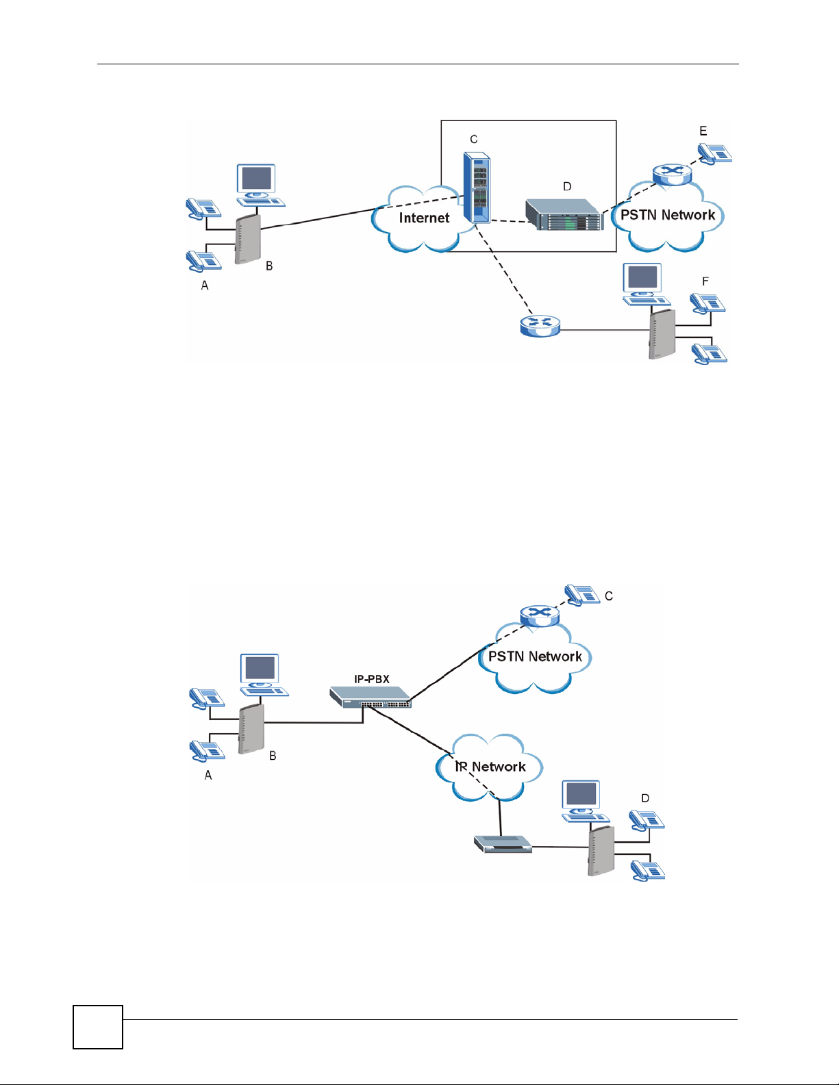
Chapter 1 Introducing the ZyXEL Device
Figure 2 VoIP Service Provider Application
1.5.2 Make Calls via IP-PBX
If your company has an IP-PBX (Internet Protocol Private Branch Exchange), you can use the
ZyXEL Device to make and receive VoIP telephone calls through it.
In this example, you use your analog phone (A in the figure) and the ZyXEL Device (B)
changes the call into VoIP and sends it to the IP-PBX. For PSTN phones (C), the IP-PBX
forwards calls through the PSTN network. For IP phones (D), the IP-PBX forwards calls
through an IP network (this could include the Internet).
Figure 3 IP-PBX Application
30
P-2304R-P1 Series User’s Guide
Page 31

1.5.3 Make Peer-to-peer Calls
Use the ZyXEL Device to make a call to the recipient’s IP address without using a SIP proxy
server. Peer-to-peer calls are also called “Point to Point” or “IP-to-IP” calls. You must know
the peer’s IP address in order to do this.
The following figure shows a basic example of how you would make a peer-to-peer VoIP call.
You use your analog phone (A in the figure) and the ZyXEL Device (B) changes the call into
VoIP. The ZyXEL Device then sends your call through the Internet to the peer VoIP device
(C).
Figure 4 Peer-to-peer Calling
Chapter 1 Introducing the ZyXEL Device
P-2304R-P1 Series User’s Guide
31
Page 32

Chapter 1 Introducing the ZyXEL Device
32
P-2304R-P1 Series User’s Guide
Page 33

CHAPTER 2
Introducing the Web
Configurator
This chapter describes how to access the ZyXEL Device web configurator and provides an
overview of its screens.
2.1 Web Configurator Overview
The web configurator is an HTML-based management interface that allows easy ZyXEL
Device setup and management via Internet browser. Use Internet Explorer 6.0 and later or
Netscape Navigator 7.0 and later versions. The recommended screen resolution is 1024 by 768
pixels.
In order to use the web configurator you need to allow:
• Web browser pop-up windows from your device. Web pop-up blocking is enabled by
default in Windows XP SP (Service Pack) 2.
• JavaScripts (enabled by default).
• Java permissions (enabled by default).
See the troubleshooting chapter if you want to make sure these functions are allowed in
Internet Explorer or Netscape Navigator.
2.2 Accessing the Web Configurator
1 Make sure your ZyXEL Device hardware is properly connected and prepare your
computer/computer network to connect to the ZyXEL Device (refer to the Quick Start
Guide).
2 Launch your web browser.
3 Type "192.168.1.1" (the ZyXEL Device’s default LAN IP address) as the URL. The
Login screen appears.
P-2304R-P1 Series User’s Guide
33
Page 34

Chapter 2 Introducing the Web Configurator
Figure 5 Login Screen
4 Type "1234" (default) as the password, and click Login. In some versions, the default
password appears automatically - if this is the case, click Login. The Change Password
screen appears.
Figure 6 Change Password Screen
34
5 It is highly recommended to change your password. To change your password, type a
new password, retype it to confirm it, and click Apply. Otherwise, click Ignore if you do
not want to change your password right now. The options screen should appear.
P-2304R-P1 Series User’s Guide
Page 35

Chapter 2 Introducing the Web Configurator
Figure 7 Select Mode Screen
6 In the options screen,
• Click Go to Wizard setup if you are logging in for the first time or if you want to make
basic changes. See Chapter 4 on page 51 for more information.
• Click Go to Advanced setup if you want to configure features that are not available in the
wizards. The main screen appears. See Section 2.4 on page 36 for more information.
• Click Exit if you want to log out.
" For security reasons, the ZyXEL Device automatically logs you out if you do not
use the web configurator for five minutes. If this happens, log in again.
2.3 Resetting the ZyXEL Device
Reset the ZyXEL Device in the following situations:
• You forgot your password.
• You cannot access the device using the web configurator. Check Troubleshooting in the
Quick Start Guide to make sure you cannot access the device anymore.
If you reset the ZyXEL Device, you lose all of the changes you have made. The ZyXEL
Device re-loads its default settings, and the password resets to “1234”. You have to make all
of your changes again.
" You will lose all of your changes when you push the RESET button.
To reset the ZyXEL Device,
P-2304R-P1 Series User’s Guide
35
Page 36

Chapter 2 Introducing the Web Configurator
1 Make sure the POWER LED is on and not blinking.
2
Press and hold the RESET button for five to ten seconds. Release the RESET button
when the POWER LED begins to blink. The default settings have been restored.
If the ZyXEL Device restarts automatically, wait for the ZyXEL Device to finish restarting,
and log in to the web configurator. The password is “1234”. You have finished.
If the ZyXEL Device does not restart automatically,
Device’s power. Then, follow the directions above again.
2.4 Web Configurator Main Screen
Figure 8 Main Screen
A
B
C
disconnect and reconnect the ZyXEL
36
D
As illustrated above, the main screen is divided into these parts:
• A - title bar
• B - navigation panel
• C - main window
• D - status bar
P-2304R-P1 Series User’s Guide
Page 37

Chapter 2 Introducing the Web Configurator
2.4.1 Title Bar
The title bar provides some icons in the upper right corner.
The icons provide the following functions.
Table 2 Web Configurator Icons in the Title Bar
ICON DESCRIPTION
Help: Click this icon to open the help page for the current screen.
Wizards: Click this icon to open one of the web configurator wizards. See Chapter 4
on page 51 for more information.
Logout: Click this icon to log out of the web configurator.
2.4.2 Navigation Panel
Use the menu items on the navigation panel to open screens to configure ZyXEL Device
features. The following tables describe each menu item.
Table 3 Navigation Panel Summary
LINK TAB FUNCTION
Status This screen contains administrative and system-related information.
Network
WAN Internet
Connection
Advanced Use this screen to set up DNS, RIP, multicasting, and Windows Networking
Traffic Redirect Use this screen to specify up a backup gateway in case the main one is not
LAN IP Use this screen to set up your LAN’s IP address and subnet mask.
DHCP Setup Use this screen to configure the ZyXEL Device’s DHCP server and DNS
Static DHCP Use this screen to assign static IP addresses to MAC addresses.
Client List Use this screen to look at which network clients are using the DHCP server.
IP Alias Use this screen to partition your LAN interface into subnets.
Advanced Use this screen to set up RIP, multicasting, Any IP, and Windows
NAT General Use this screen to enable and disable NAT features.
Port Forwarding Use this screen to forward traffic to specific IP addresses based on the
Trigger Port Use this screen to change your ZyXEL Device’s trigger port settings.
ALG Use this screen to enable and disable the ZyXEL Device’s ALG.
VoIP
SIP SIP Settings Use this screen to configure your ZyXEL Device’s Voice over IP settings.
QoS Use this screen to configure your ZyXEL Device’s Quality of Service
Use this screen to set up ISP parameters, IP addresses, and MAC
addresses.
for your WAN port.
available.
server settings.
Networking for your LAN port.
destination port.
settings.
P-2304R-P1 Series User’s Guide
37
Page 38

Chapter 2 Introducing the Web Configurator
Table 3 Navigation Panel Summary
LINK TAB FUNCTION
Phone Analog Phone Use this screen to set up which SIP accounts use which phone ports for
incoming and outgoing calls.
Common Use this screen to configure general phone port settings.
Region Use this screen to set up regional and call service settings.
Phone Book Incoming Call
Policy
Speed Dial Use this screen to configure speed dial numbers for SIP phone numbers.
Security
Firewall General Use this screen to activate/deactivate the firewall and log packets related to
Services Use this screen to enable service blocking (LAN to WAN firewall rules).
Content Filter Filter Use this screen to block sites containing certain keywords in the URL.
Schedule Use this screen to set the days and times for the ZyXEL Device to perform
Management
Static Route IP Static Route Use this screen to configure IP static routes.
Bandwidth
MGMT
Remote MGMT WWW Use this screen to configure through which interface(s) and from which IP
UPnP General Use this screen to enable UPnP on the ZyXEL Device.
Maintenance
System General Use this screen to configure general system settings.
Logs View Log Use this screen to view the logs for the categories that you selected.
To ol s Firmware Use this screen to upload firmware to your ZyXEL Device.
Summary Use this screen to enable bandwidth management on an interface and set
Class Setup Use this screen to define bandwidth classes.
Monitor Use this screen to view bandwidth class statistics.
Telnet Use this screen to configure through which interface(s) and from which IP
FTP Use this screen to configure through which interface(s) and from which IP
SNMP Use this screen to configure your ZyXEL Device’s settings for Simple
DNS Use this screen to configure through which interface(s) and from which IP
Security Use this screen to change your anti-probing settings.
Dynamic DNS Use this screen to set up dynamic DNS.
Time Setting Use this screen to change your ZyXEL Device’s time and date.
Log Settings Use this screen to change your ZyXEL Device’s log settings.
Configuration Use this screen to backup and restore the configuration or reset the factory
Restart Use this screen to reboot the ZyXEL Device without turning the power off.
Use this screen to set up call forwarding rules.
firewall rules.
content filtering
the maximum allowed bandwidth and scheduler for the interface.
address(es) users can use HTTP to manage the ZyXEL Device.
address(es) users can use Telnet to manage the ZyXEL Device.
address(es) users can use FTP to access the ZyXEL Device.
Network Management Protocol management.
address(es) users can send DNS queries to the ZyXEL Device.
defaults to your ZyXEL Device.
38
P-2304R-P1 Series User’s Guide
Page 39

2.4.3 Main Window
The main window shows the screen you select in the navigation panel. It is discussed in more
detail in the rest of this document.
Right after you log in, the Status screen is displayed. See Chapter 3 on page 41 for more
information about the Status screen.
2.4.4 Status Bar
Check the status bar when you click Apply or OK to verify that the configuration has been
updated.
Chapter 2 Introducing the Web Configurator
P-2304R-P1 Series User’s Guide
39
Page 40

Chapter 2 Introducing the Web Configurator
40
P-2304R-P1 Series User’s Guide
Page 41

CHAPTER 3
Status Screens
Use the Status screens to look at the current status of the device, system resources, interfaces
(LAN and WAN), and SIP accounts. You can also register and unregister SIP accounts. The
Status screen also provides detailed information from Any IP and DHCP and statistics from
VoIP, bandwidth management, and traffic.
3.1 Status Screen
Use this screen to look at the current status of the device, system resources, interfaces (LAN
and WAN), and SIP accounts. You can also register and unregister SIP accounts.
Click Status to open this screen.
P-2304R-P1 Series User’s Guide
41
Page 42

Chapter 3 Status Screens
Figure 9 Status Screen
Each field is described in the following table.
Table 4 Status Screen
LABEL DESCRIPTION
Refresh Interval Enter how often you want the ZyXEL Device to update this screen.
Refresh Now Click this to update this screen immediately.
Device
Information
System Name This field displays the ZyXEL Device system name. It is used for identification.
Firmware Version This field displays the current version of the firmware inside the ZyXEL Device. It
WAN Information
IP Address This field displays the current IP address of the ZyXEL Device in the WAN.
IP Subnet
Mask
You can change this in the Configuration Wizard or Maintenance > System >
General screen.
also shows the date the firmware version was created. You can change the
firmware version by uploading new firmware in Maintenance > Tools >
Firmware.
This field displays the current subnet mask in the WAN.
42
P-2304R-P1 Series User’s Guide
Page 43

Chapter 3 Status Screens
Table 4 Status Screen
LABEL DESCRIPTION
DHCP This field displays what DHCP services the ZyXEL Device is using in the WAN.
Choices are:
Client - The ZyXEL Device is a DHCP client in the WAN. Its IP address comes
from a DHCP server on the WAN.
None - The ZyXEL Device is not using any DHCP services in the WAN. It has a
static IP address.
If you are not using Roadrunner on Ethernet, you can change this in Network >
WAN. If you are using Roadrunner on Ethernet, this is controlled by Roadrunner.
LAN Information
IP Address This field displays the current IP address of the ZyXEL Device in the LAN.
IP Subnet
Mask
DHCP This field displays what DHCP services the ZyXEL Device is providing to the LAN.
System Status
System Up Time This field displays how long the ZyXEL Device has been running since it last
Current Date/
Time
System Resource
CPU Usage This field displays what percentage of the ZyXEL Device’s processing ability is
Memory
Usage
Interface Status
Interface This column displays each interface the ZyXEL Device has.
Status This field indicates whether or not the ZyXEL Device is using the interface.
This field displays the current subnet mask in the LAN.
Choices are:
Server - The ZyXEL Device is a DHCP server in the LAN. It assigns IP addresses
to other computers in the LAN.
None - The ZyXEL Device is not providing any DHCP services to the WAN.
You can change this in Network > LAN > DHCP Setup.
started up. The ZyXEL Device starts up when you plug it in, when you restart it
(Maintenance > Tools > Restart), or when you reset it (see Section 2.3 on page
35).
This field displays the current date and time in the ZyXEL Device. You can change
this in Maintenance > System > Time Setting.
currently used. When this percentage is close to 100%, the ZyXEL Device is
running at full load, and the throughput is not going to improve anymore. If you
want some applications to have more throughput, you should turn off other
applications (for example, using bandwidth management; see Chapter 15 on page
153.
This field displays what percentage of the ZyXEL Device’s memory is currently
used. Usually, this percentage should not increase much. If memory usage does
get close to 100%, the ZyXEL Device is probably becoming unstable, and you
should restart the device. See Section 20.2.5 on page 213, or turn off the device
(unplug the power) for a few seconds.
Up - The ZyXEL Device is using the interface.
Down - The ZyXEL Device is not using the interface.
P-2304R-P1 Series User’s Guide
43
Page 44

Chapter 3 Status Screens
Table 4 Status Screen
LABEL DESCRIPTION
Rate If the interface uses Ethernet encapsulation, this column displays the port speed
Summary
Any IP Table Click (Details ...) to open the Any IP Table window. See Section 3.2 on page 44.
DHCP Table Click (Details ...) to open the DHCP Table window. See Section 3.3 on page 45.
VoIP Statistics Click (Details ...) to open the VoIP Statistics window. See Section 3.4 on page
BW MGMT
Monitor
Packet Statistics Click (Details ...) to open the Packet Statistics window. See Section 3.6 on page
VoIP Status
Account This column displays each SIP account in the ZyXEL Device.
Registration This field displays the current registration status of the SIP account. You have to
URI This field displays the account number and service domain of the SIP account.
and the Ethernet duplex setting. Duplex settings are:
Full - The ZyXEL Device is using full-duplex Ethernet.
Half - The ZyXEL Device is using half-duplex Ethernet.
You cannot change the Ethernet duplex setting in the ZyXEL Device.
If this interface uses PPPoE encapsulation, this column displays the port speed
and the status of the call.
Down - The connection is not available.
Dial - The ZyXEL Device is making the call.
Idle - The call is connected.
Drop - The ZyXEL Device is ending the call.
The LAN interface always uses Ethernet encapsulation. You can change the
encapsulation of the WAN interface in Network > WAN > Internet Connection.
46.
Click (Details ...) to open the BW MGMT Monitor window. See Section 3.5 on
page 47.
49.
register SIP accounts with a SIP server to use VoIP.
If the SIP account is already registered with the SIP server,
• Click Unregister to delete the SIP account’s registration in the SIP server.
This does not cancel your SIP account, but it deletes the mapping between
your SIP identity and your IP address or domain name.
• The second field displays Registered.
If the SIP account is not registered with the SIP server,
• Click Register to have the ZyXEL Device attempt to register the SIP account
with the SIP server.
• The second field displays the reason the account is not registered.
Inactive - The SIP account is not active. You can activate it in VoIP > SIP > SIP
Settings.
Not Register - The SIP account is active, but you have not tried to register it yet.
Register Fail - The last time the ZyXEL Device tried to register the SIP account
with the SIP server, the attempt failed.
You can change these in VoIP > SIP > SIP Settings.
3.2 Any IP Table
To access this screen, open the Status screen (see Section 3.1 on page 41), and click (Details
...) next to Any IP Table.
44
P-2304R-P1 Series User’s Guide
Page 45

Chapter 3 Status Screens
Figure 10 Any IP Table
Each field is described in the following table.
Table 5 Any IP Table
LABEL DESCRIPTION
# This field is a sequential value. It is not associated with a specific entry.
IP Address This field displays the IP address of each computer that is using the ZyXEL Device
MAC Address
Refresh
but is in a different subnet than the ZyXEL Device.
This field displays the MAC address of the computer that is using the ZyXEL
Device but is in a different subnet than the ZyXEL Device.
Click this to update this screen.
3.3 DHCP Table
To access this screen, open the Status screen (see Section 3.1 on page 41), and click (Details
...) next to DHCP Table.
Figure 11 DHCP Table
Each field is described in the following table.
Table 6 DHCP Table
LABEL DESCRIPTION
# This field is a sequential value. It is not associated with a specific entry.
IP Address
Host Name
MAC Address
Refresh
This field displays the IP address the ZyXEL Device assigned to a computer in the
network.
This field displays the system name of the computer to which the ZyXEL Device
assigned the IP address.
This field displays the MAC address of the computer to which the ZyXEL Device
assigned the IP address.
Click this to update this screen.
P-2304R-P1 Series User’s Guide
45
Page 46

Chapter 3 Status Screens
3.4 VoIP Statistics
To access this screen, open the Status screen (see Section 3.1 on page 41), and click (Details
...) next to VoIP Statistics.
Figure 12 VoIP Statistics
Each field is described in the following table.
Table 7 VoIP Statistics
LABEL DESCRIPTION
SIP Status
Account This column displays each SIP account in the ZyXEL Device.
Registration This field displays the current registration status of the SIP account. You can
change this in the Status screen.
Registered - The SIP account is registered with a SIP server.
Register Fail - The last time the ZyXEL Device tried to register the SIP account
with the SIP server, the attempt failed. The ZyXEL Device automatically tries to
register the SIP account when you turn on the ZyXEL Device or when you activate
it.
Inactive - The SIP account is not active. You can activate it in VoIP > SIP > SIP
Settings.
Last Registration This field displays the last time you successfully registered the SIP account. It
URI This field displays the account number and service domain of the SIP account.
Protocol This field displays the transport protocol the SIP account is currently using.
Message Waiting This field indicates whether or not there are any messages waiting for the SIP
Last Incoming
Number
Last Outgoing
Number
displays N/A if you never successfully registered this account.
You can change these in VoIP > SIP > SIP Settings.
account.
This field displays the last number that called the SIP account. It displays N/A if no
number has ever dialed the SIP account.
This field displays the last number the SIP account called. It displays N/A if the
SIP account has never dialed a number.
46
P-2304R-P1 Series User’s Guide
Page 47

Chapter 3 Status Screens
Table 7 VoIP Statistics
LABEL DESCRIPTION
Call Statistics
Phone This field displays each phone port in the ZyXEL Device.
Hook This field indicates whether the phone is on the hook or off the hook.
On - The phone is hanging up or already hung up.
Off - The phone is dialing, calling, or connected.
Status This field displays the current status of each call.
DIAL - The ZyXEL Device is dialing the current call.
RING - The phone is ringing because there is an incoming call.
Process - The call is connected and in process.
DROP - The ZyXEL Device is hanging up (disconnecting) the current call.
DISC - The ZyXEL Device has hung up.
N/A - There is no phone connected to this phone port.
Codec This field displays the type of voice compression used in the current call.
Peer Number If the current call is a peer-to-peer call, this field displays the SIP number of the
Duration This field displays how long the current call has lasted.
Tx Pkts This field displays the number of packets the ZyXEL Device has transmitted in the
Rx Pkts This field displays the number of packets the ZyXEL Device has received in the
Tx B/s This field displays how quickly the ZyXEL Device has transmitted packets in the
Rx B/s This field displays how quickly the ZyXEL Device has received packets in the
Poll Interval Enter how often you want the ZyXEL Device to update this screen, and click Set
Set Interval Click this to make the ZyXEL Device update the screen based on the amount of
Stop Click this to make the ZyXEL Device stop updating the screen.
other party. Otherwise, it displays N/A.
current call.
current call.
current call. The rate is the number of kilobits transmitted one second before the
last time the screen updated (refreshed).
current call. The rate is the number of kilobits received one second before the last
time the screen updated (refreshed).
Interval.
time you specified in Poll Interval.
3.5 BW MGMT Monitor
To access this screen, open the Status screen (see Section 3.1 on page 41), and click (Details
...) next to BW MGMT Monitor.
P-2304R-P1 Series User’s Guide
47
Page 48

Chapter 3 Status Screens
Figure 13 BW MGMT Monitor
The types of traffic shown in this screen do not depend on your settings in the Bandwidth
Management Wizard or in Bandwidth MGMT. Each field is described in the following
table.
Table 8 BW MGMT Monitor
LABEL DESCRIPTION
LAN-VoIP (SIP) This field displays how much SIP traffic is going to the LAN each second. The rate
LAN-FTP This field displays how much FTP traffic is going to the LAN each second. The rate
LAN-E-Mail This field displays how much e-mail went to the LAN each second. The rate is the
LAN-WWW This field displays how much web traffic went to the LAN each second. The rate is
Default Class This field displays how much traffic that is not allocated to any sub-class went to
WAN-VoIP (SIP) This field displays how much SIP traffic went to the WAN each second. The rate is
is the number of kilobits that went to the LAN one second before the last time the
screen updated (refreshed).
is the number of kilobits that went to the LAN one second before the last time the
screen updated (refreshed).
number of kilobits that went to the LAN one second before the last time the screen
updated (refreshed).
the number of kilobits that went to the LAN one second before the last time the
screen updated (refreshed).
the LAN each second. The rate is the number of kilobits that went to the LAN one
second before the last time the screen updated (refreshed). This might include
SIP traffic, FTP traffic, e-mail, or web traffic, depending on what traffic is allocated
to sub-classes. You can change what traffic is allocated to sub-classes in
Management > Bandwidth MGMT > Class Setup.
the number of kilobits that went to the WAN one second before the last time the
screen updated (refreshed).
48
P-2304R-P1 Series User’s Guide
Page 49

Chapter 3 Status Screens
Table 8 BW MGMT Monitor
LABEL DESCRIPTION
WAN-FTP This field displays how much FTP traffic went to the WAN each second. The rate
is the number of kilobits that went to the WAN one second before the last time the
screen updated (refreshed).
WAN-E-Mail This field displays how much e-mail went to the WAN each second. The rate is the
number of kilobits that went to the WAN one second before the last time the
screen updated (refreshed).
Default Class This field displays how much traffic that is not allocated to any sub-class went to
the WAN each second. The rate is the number of kilobits that went to the WAN
one second before the last time the screen updated (refreshed). This might
include SIP traffic, FTP traffic, e-mail, or web traffic, depending on what traffic is
allocated to sub-classes. You can change what traffic is allocated to sub-classes
in Management > Bandwidth MGMT > Class Setup.
Poll Interval Enter how often you want the ZyXEL Device to update this screen, and click Set
Interval.
Set Interval Click this to make the ZyXEL Device update the screen based on the amount of
Stop Click this to make the ZyXEL Device stop updating the screen.
time you specified in Poll Interval.
3.6 Packet Statistics
To access this screen, open the Status screen (see Section 3.1 on page 41), and click (Details
...) next to Packet Statistics.
Figure 14 Packet Statistics
P-2304R-P1 Series User’s Guide
49
Page 50

Chapter 3 Status Screens
Each field is described in the following table.
Table 9 Packet Statistics Window
LABEL DESCRIPTION
Port This field displays each port in the ZyXEL Device.
Status
Tx Pkts
Rx Pkts
Collisions
Tx B/s This field displays how quickly the ZyXEL Device has transmitted packets from the
Rx B/s This field displays how quickly the ZyXEL Device has received packets from the
Up Time This is the total amount of time the port has been connected.
System Up Time
Poll Interval Enter how often you want the ZyXEL Device to update this screen, and click Set
Set Interval Click this to make the ZyXEL Device update the screen based on the amount of
Stop Click this to make the ZyXEL Device stop updating the screen.
If the port is not connected to anything, this field displays Down.
If the interface uses Ethernet encapsulation, this field displays the port speed and
the Ethernet duplex setting. Duplex settings are:
Full - The ZyXEL Device is using full-duplex Ethernet.
Half - The ZyXEL Device is using half-duplex Ethernet.
You cannot change the Ethernet duplex setting in the ZyXEL Device.
If this interface uses PPPoE encapsulation, this field displays the port speed and
the status of the call.
Down - The connection is not available.
Dial - The ZyXEL Device is making the call.
Idle - The call is connected.
Drop - The ZyXEL Device is ending the call.
The LAN interface always uses Ethernet encapsulation. You can change the
encapsulation of the WAN interface in Network > WAN > Internet Connection.
This field displays the number of packets the ZyXEL Device has transmitted from
the port.
This field displays the number of packets the ZyXEL Device has received from the
port.
This field displays the number of collisions detected by the port.
port. The rate is the number of bytes transmitted one second before the last time
the screen updated (refreshed).
port. The rate is the number of bytes received one second before the last time the
screen updated (refreshed).
This field displays how long the ZyXEL Device has been running since it last
started up. The ZyXEL Device starts up when you plug it in, when you restart it
(Maintenance > Tools > Restart), or when you reset it (see Section 2.3 on page
35).
Interval.
time you specified in Poll Interval.
50
P-2304R-P1 Series User’s Guide
Page 51

CHAPTER 4
Wizard Setup
This chapter provides information on the wizards in the web configurator.
4.1 Main Wizard Screen
Use this screen to open one of the wizards in the ZyXEL Device. To access this screen, click
Go to Wizard setup in the Login Options screen, or click the Wizard icon in the upper right
corner of the main screen.
Figure 15 Main Wizard Screen
P-2304R-P1 Series User’s Guide
51
Page 52

Chapter 4 Wizard Setup
The following table describes the labels in this screen.
Table 10 Main Wizard Screen
LABEL DESCRIPTION
CONNECTION
WIZARD
VOIP SETUP Click this to open the VoIP Setup Wizard. See Section 4.3 on page 62.
BANDWIDTH
MANAGEMENT
WIZARD
Exit Click this to close this screen and return to the main screen.
Click this to open the Connection Wizard. See Section 4.2 on page 52.
Click this to open the Bandwidth Management Wizard. See Section 4.4 on page
65.
4.2 Connection Wizard
Use this wizard to set up your Internet connection. See Chapter 6 on page 75 for more
information.
" You cannot use the Connection Wizard to set up your Internet connection in the
following situations:
- You subscribe to a Roadrunner service.
- You use PPPoE encapsulation and the remote server cannot be discovered
automatically.
In these cases, you must use the screens discussed in Chapter 6 on page 75.
" Some ISPs, such as Telstra, send UDP heartbeat packets to verify that the
customer is still online. In this case, you have to create a WAN to LAN firewall
rule for those packets. Contact your ISP to find the correct port number.
52
P-2304R-P1 Series User’s Guide
Page 53

4.2.1 Welcome
Figure 16 Connection Wizard > Welcome
Chapter 4 Wizard Setup
The following table describes the labels in this screen.
Tabl e 11 Connection Wizard > Welcome
LABEL DESCRIPTION
< Back Click this to go to the previous screen.
Next > Click this to go to the next screen.
Exit Click this to close this screen and return to the main screen.
4.2.2 System Information
" Usually, you should just click Next in this screen.
P-2304R-P1 Series User’s Guide
53
Page 54

Chapter 4 Wizard Setup
Figure 17 Connection Wizard > System Information
The following table describes the labels in this screen.
Table 12 Connection Wizard > System Information
LABEL DESCRIPTION
System Name Enter your computer's "Computer Name". See Section 18.1 on page 187 for more
Domain Name Enter the domain name entry that is propagated to DHCP clients on the LAN. If
< Back Click this to go to the previous screen.
Next > Click this to go to the next screen.
Exit Click this to close this screen and return to the main screen.
4.2.3 ISP Parameters
This screen depends on the Connection Type you select.
information. This is for identification purposes, but some ISPs also check this field.
This name can be up to 30 alphanumeric characters long. Spaces are not allowed,
but dashes “-” and underscores "_" are accepted.
you leave this blank, the domain name obtained from the ISP is used. Use up to
38 alphanumeric characters. Spaces are not allowed, but dashes “-” and periods
"." are accepted.
54
P-2304R-P1 Series User’s Guide
Page 55

Chapter 4 Wizard Setup
4.2.3.1 Ethernet
" You cannot use the Connection Wizard if you subscribe to a Roadrunner
service. You must use the screens discussed in Chapter 6 on page 75 instead.
Figure 18 Connection Wizard > ISP Parameters (Ethernet)
The following table describes the labels in this screen.
Table 13 Connection Wizard > ISP Parameters (Ethernet)
LABEL DESCRIPTION
Connection Type Select Ethernet.
< Back Click this to go to the previous screen.
Next > Click this to go to the next screen.
Exit Click this to close this screen and return to the main screen.
4.2.3.2 PPPoE
Point-to-Point Protocol over Ethernet (PPPoE) functions as a dial-up connection. PPPoE is an
IETF (Internet Engineering Task Force) standard specifying how a host personal computer
interacts with a broadband modem (for example DSL, cable, wireless, etc.) to achieve access
to high-speed data networks.
P-2304R-P1 Series User’s Guide
55
Page 56

Chapter 4 Wizard Setup
" You cannot use the Connection Wizard if the PPPoE remote server cannot be
discovered automatically. You must use the screens discussed in Chapter 6 on
page 75 instead.
Figure 19 Connection Wizard > ISP Parameters (PPPoE)
56
The following table describes the labels in this screen.
Table 14 Connection Wizard > ISP Parameters (PPPoE)
LABEL DESCRIPTION
Connection Type Select PPP over Ethernet.
Service Name Enter the PPP service name provided by your ISP. If your ISP did not provide a
service name, leave this field blank.
User Name Enter the user name provided by your ISP.
Password Enter the password provided by your ISP.
< Back Click this to go to the previous screen.
Next > Click this to go to the next screen.
Exit Click this to close this screen and return to the main screen.
P-2304R-P1 Series User’s Guide
Page 57

4.2.4 Your IP Address
Figure 20 Connection Wizard > IP Address
Chapter 4 Wizard Setup
The following table describes the labels in this screen.
Table 15 Connection Wizard > IP Address
LABEL DESCRIPTION
Get automatically
from your ISP
Use fixed IP
address provided
by your ISP
< Back Click this to go to the previous screen.
Next > Click this to go to the next screen.
Exit Click this to close this screen and return to the main screen.
Select this if your ISP did not assign you a static IP address.
Select this if your ISP assigned you a static IP address.
4.2.5 WAN IP Address Assignment
This screen appears if you select Use fixed IP address provided by your ISP in the previous
screen. Use this screen to set up your static IP address. The fields depend on the Connection
Type you select in the ISP Parameters screen.
P-2304R-P1 Series User’s Guide
57
Page 58

Chapter 4 Wizard Setup
4.2.5.1 Ethernet
Figure 21 Connection Wizard > IP Address (Ethernet)
The following table describes the labels in this screen.
Table 16 Connection Wizard > IP Address (Ethernet)
LABEL DESCRIPTION
My WAN IP
Address
My WAN IP
Subnet Mask
Gateway IP
Address
DNS Server Address Assignment (if applicable)
DNS (Domain Name System) is for mapping a domain name to its corresponding IP address and vice
versa. The DNS server is extremely important because without it, you must know the IP address of a
computer before you can access it. The ZyXEL Device uses a system DNS server (in the order you
specify here) to resolve domain names for VPN, DDNS and the time server.
First DNS Server
Second DNS
Server
Third DNS Server
Enter the IP address provided by your ISP.
Enter the subnet mask provided by your ISP.
Enter the gateway provided by your ISP. If your ISP did not provide one, leave it
blank.
Select From ISP if your ISP dynamically assigns DNS server information. (In this
case, the ISP assigns the WAN IP address too. See Network > WAN > Internet
Connection.) The field to the right is read-only, and it displays the IP address
provided by your ISP.
Select User-Defined if you have the IP address of a DNS server. You might get it
from your ISP or from your network. Enter the IP address in the field to the right.
Select None if you do not want to use this DNS server. If you select None for all of
the DNS servers, you must use IP addresses to configure the ZyXEL Device and
to access the Internet.
58
P-2304R-P1 Series User’s Guide
Page 59

Chapter 4 Wizard Setup
Table 16 Connection Wizard > IP Address (Ethernet)
LABEL DESCRIPTION
< Back Click this to go to the previous screen.
Next > Click this to go to the next screen.
Exit Click this to close this screen and return to the main screen.
4.2.5.2 PPPoE
" You cannot use the Connection Wizard if the PPPoE remote server cannot be
discovered automatically.
Figure 22 Connection Wizard > IP Address (PPPoE)
P-2304R-P1 Series User’s Guide
59
Page 60

Chapter 4 Wizard Setup
The following table describes the labels in this screen.
Table 17 Connection Wizard > IP Address (PPPoE)
LABEL DESCRIPTION
My WAN IP
Address
First DNS Server
Second DNS
Server
Third DNS Server
< Back Click this to go to the previous screen.
Next > Click this to go to the next screen.
Exit Click this to close this screen and return to the main screen.
4.2.6 MAC Address
Enter the IP address provided by your ISP.
Select From ISP if your ISP dynamically assigns DNS server information. (In this
case, the ISP assigns the WAN IP address too. See Network > WAN > Internet
Connection.) The field to the right is read-only, and it displays the IP address
provided by your ISP.
Select User-Defined if you have the IP address of a DNS server. You might get it
from your ISP or from your network. Enter the IP address in the field to the right.
Select None if you do not want to use this DNS server. If you select None for all of
the DNS servers, you must use IP addresses to configure the ZyXEL Device and
to access the Internet.
Figure 23 Connection Wizard > MAC Address
60
P-2304R-P1 Series User’s Guide
Page 61

The following table describes the labels in this screen.
Table 18 Connection Wizard > MAC Address
LABEL DESCRIPTION
Factory default Select this if you want to use the default MAC address for the ZyXEL Device.
Spoof this
computer’s MAC
Address
IP Address This field is enabled if you select Spoof this computer's MAC Address.
< Back Click this to go to the previous screen.
Apply > Click this to configure the ZyXEL Device and go to the next screen.
Exit Click this to close this screen and return to the main screen.
4.2.7 Finish
Figure 24 Connection Wizard > Finish
Chapter 4 Wizard Setup
Select this if you do not want to use the default MAC address for the ZyXEL
Device.
Enter the IP address of the computer whose MAC address you want the ZyXEL
Device to use instead of the default MAC address.
P-2304R-P1 Series User’s Guide
61
Page 62

Chapter 4 Wizard Setup
The following table describes the labels in this screen.
Table 19 Connection Wizard > Finish
LABEL DESCRIPTION
Go to Bandwidth
Management
Wizard (optional)
Finish Click this to close this screen and return to the main screen.
Click this to start the Bandwidth Management Wizard. See Section 4.4 on page
65.
4.3 VoIP Setup Wizard
Use this wizard to set up your VoIP account(s). Leave the default settings in fields if your
VoIP service provider (the company that lets you make phone calls over the Internet) did not
provide any information. See Chapter 9 on page 107 for more information.
" You must have a SIP account before you can use this wizard.
4.3.1 SIP Settings
Figure 25 VoIP Setup Wizard > SIP Settings
62
P-2304R-P1 Series User’s Guide
Page 63

Chapter 4 Wizard Setup
The following table describes the labels in this screen.
Table 20 VoIP Setup Wizard > SIP Settings
LABEL DESCRIPTION
SIP Settings
SIP Number Enter your SIP number. In the full SIP URI (like 1234@VoIP-provider.com), this
is the part before the @ symbol. You can use up to 127 printable ASCII
characters.
SIP Server
Address
SIP Service
Domain
Authentication
User Name Enter the user name for registering this SIP account, exactly as it was given to
Password Enter the user name for registering this SIP account, exactly as it was given to
Check here to set
up SIPx settings
< Back Click this to go to the previous screen.
Apply Click this to go to the next screen. If you select Check here to set up SIPx
Enter the IP address or domain name of the SIP server provided by your VoIP
service provider. You can use up to 95 printable ASCII characters. It does not
matter whether the SIP server is a proxy, redirect or register server.
Enter the SIP service domain name. In the full SIP URI (like 1234@VoIP-
provider.com), this is the part after the @ symbol. You can use up to 127 printable
ASCII Extended set characters.
you. You can use up to 95 printable ASCII characters.
you. You can use up to 95 printable ASCII Extended set characters.
This field is available in the SIP Settings screen.
Select this if you want to set up other SIP account(s), as well as the SIP1 account.
settings, the SIP Settings screen appears again for SIP2, SIP3 or SIP 4.
Otherwise, the ZyXEL Device tries to register your SIP account(s). The following
screen appears.
Figure 26 VoIP Setup Wizard > Registration Test
Wait until it finishes.
Exit Click this to close this screen and return to the main screen.
4.3.2 Registration Complete
This screen depends on whether or not the ZyXEL Device successfully registered your SIP
account(s).
P-2304R-P1 Series User’s Guide
63
Page 64

Chapter 4 Wizard Setup
Figure 27 VoIP Setup Wizard > Registration Complete (Success)
The following table describes the labels in this screen.
Table 21 VoIP Setup Wizard > Registration Complete (Success)
LABEL DESCRIPTION
Return to Wizard
Main Page
Go to Advanced
Setup page
Finish Click this to close this screen and return to the main screen.
Click this to open the main wizard screen. See Section 4.1 on page 51.
Click this to close this screen and return to the main screen.
If the ZyXEL Device cannot register your SIP account(s), see the Quick Start Guide for
troubleshooting suggestions.
64
P-2304R-P1 Series User’s Guide
Page 65

Figure 28 VoIP Setup Wizard > Registration Complete (Fail)
Chapter 4 Wizard Setup
The following table describes the labels in this screen.
Table 22 VoIP Setup Wizard > Registration Complete (Fail)
LABEL DESCRIPTION
< Back Click this to go to the previous screen.
Register Again Click this if you want the ZyXEL Device to try to register your SIP account(s)
again.
Exit Click this to close this screen and return to the main screen. The ZyXEL Device
saves the information you provided.
4.4 Bandwidth Management Wizard
Use this wizard to control how much traffic can pass through your ZyXEL Device and the
priority of each service (application) that can use it. Each service you select is guaranteed a
small amount of bandwidth. The remaining bandwidth is divided by priority. If one service has
higher priority than another, then the first service uses as much of the remaining bandwidth as
it needs. If there is no more bandwidth for the second service, then it waits. If you do not select
a service in this wizard (or if you do not find a particular service), the service can still use
bandwidth, but it does not have any guaranteed amount and it has the lowest priority. See
Chapter 15 on page 153 for more information.
P-2304R-P1 Series User’s Guide
65
Page 66

Chapter 4 Wizard Setup
4.4.1 Welcome
Figure 29 Bandwidth Management Wizard > Welcome
The following table describes the labels in this screen.
Table 23 Bandwidth Management Wizard > Welcome
LABEL DESCRIPTION
< Back Click this to go to the previous screen.
Next > Click this to go to the next screen.
Exit Click this to close this screen and return to the main screen.
66
P-2304R-P1 Series User’s Guide
Page 67

4.4.2 General Information
Figure 30 Bandwidth Management Wizard > General Information
Chapter 4 Wizard Setup
The following table describes the labels in this screen.
Table 24 Bandwidth Management Wizard > General Information
LABEL DESCRIPTION
Active Select this to enable bandwidth management. Bandwidth management applies to
Managed
Bandwidth (kbps)
< Back Click this to go to the previous screen.
Next > Click this to go to the next screen.
Exit Click this to close this screen and return to the main screen.
all traffic flowing through the router.
Enter the total amount of traffic the device can send to the WAN. It is
recommended to set this speed to what the device connected to the WAN can
handle. For example, set this field to 1000 kbps if a broadband device connected
to the WAN port has a maximum speed of 1000 kbps.
This does not affect the total amount of traffic the device can send to the LAN. See
Management > Bandwidth MGMT > Summary to do this.
P-2304R-P1 Series User’s Guide
67
Page 68

Chapter 4 Wizard Setup
4.4.3 Services Setup
Figure 31 Bandwidth Management Wizard > Services Setup
The following table describes the labels in this screen.
Table 25 Bandwidth Management Wizard > Services Setup
LABEL DESCRIPTION
Service Select the service(s) that should have higher priority when bandwidth is allocated.
If you do not select a service or if you do not see it in the list, the service can still
use bandwidth. However, it has the lowest priority.
Note: You must select at least one service in this screen.
Each service you select becomes a LAN sub-class and a WAN sub-class in
Management > Bandwidth MGMT > Class Setup.
< Back Click this to go to the previous screen.
Next > Click this to go to the next screen.
Exit Click this to close this screen and return to the main screen.
68
P-2304R-P1 Series User’s Guide
Page 69

4.4.4 Priority Setup
Figure 32 Bandwidth Management Wizard > Priority Setup
Chapter 4 Wizard Setup
The following table describes the labels in this screen.
Table 26 Bandwidth Management Wizard > Priority Setup
LABEL DESCRIPTION
Service This column displays each service you selected in the previous screen.
Priority Set the priority of each service. If a service has higher priority than other services,
< Back Click this to go to the previous screen.
Apply Click this to configure the ZyXEL Device and go to the next screen.
Exit Click this to close this screen and return to the main screen.
then it can use as much remaining bandwidth as it needs. If there is no more
bandwidth left, other services have to wait. Select Others only if you want to set
up the sub-class manually in the Bandwidth Class Edit Screen.
P-2304R-P1 Series User’s Guide
69
Page 70

Chapter 4 Wizard Setup
4.4.5 Finish
Figure 33 Bandwidth Management Wizard > Finish
The following table describes the labels in this screen.
Table 27 Bandwidth Management Wizard > Finish
LABEL DESCRIPTION
Finish Click this to close this screen and return to the main screen.
70
P-2304R-P1 Series User’s Guide
Page 71

CHAPTER 5
Bridge Mode
The ZyXEL Device supports two modes, Router and Bridge. Usually, you should use Router
mode because it supports all the features discussed in this User’s Guide. However, you might
use Bridge mode in the following situation:
• There is another router in the network; and
• You only want to use the ZyXEL Device for VoIP and Internet access. You do not want to
use other features, such as the firewall, even with their default settings.
5.1 Bridge Mode Overview
In Bridge mode, the ZyXEL Device acts like a bridge, instead of a router. A bridge is simpler
than a router. It may be more efficient in small networks, but it also offers fewer features. In
Bridge mode, your ZyXEL Device only supports the following features, by screen.
Table 28 Bridge Mode: Features by Screen
LINK TAB FUNCTION IN BRIDGE MODE
Status Same as in router mode
Network
WAN Internet
Connection
Other screens None
LAN All screens None
NAT All screens None
VoI P All screens Same as in router mode
Security All screens None
Management
Remote MGMT All screens Same as in router mode
Other screens None
Maintenance
System General Same as in router mode; you cannot re-configure the
Dynamic DNS None
Time Setting Same as in router mode
Logs All screens Same as in router mode
To ols All screens Same as in router mode
Same as in router mode; use the factory-default MAC
address.
Management IP Address.
P-2304R-P1 Series User’s Guide
71
Page 72

Chapter 5 Bridge Mode
5.2 Bridge Mode Procedure
Follow these steps to change the ZyXEL Device into Bridge mode.
1 Log in to the web configurator. (See Chapter 2 on page 33.)
2 Click Maintenance > System > General.
3 In the Mode field, select Bridge.
4 In the Management IP Address field, enter the IP address you want to use to access the
ZyXEL Device in Bridge mode. For example, enter 192.168.5.1.
5 Click Apply.
The ZyXEL Device automatically restarts. When the POWER LED stops blinking and stays
on, follow the directions in Chapter 2 on page 33 to log in to the web configurator again. Use
the Management IP Address you set up in step 4. If your computer’s IP address is in a
different subnet, follow the directions in Appendix C on page 235 to change your computer’s
IP address.
When you log in to the web configurator, you can still see every screen in Table 3 on page 37,
even if the feature is not available in Bridge mode (in Table 28 on page 71). However, if you
configure a feature that is not available in Bridge mode, your changes have no effect until you
change back to Router mode.
If you want to change back to Router mode, follow these steps.
1 Log in to the web configurator. (See Chapter 2 on page 33.)
2 Click Maintenance > System > General.
3 In the Mode field, select Router.
4 Click Apply.
5 The ZyXEL Device asks you if you want to enable the firewall and NAT. Select OK or
Cancel.
Figure 34 Prompt Before Change to Router Mode
The ZyXEL Device automatically restarts. Use the IP address in Network > LAN > IP to log
in to the web configurator again. You might have to change your computer’s IP address again.
72
P-2304R-P1 Series User’s Guide
Page 73

WA N ( 7 5 )
LAN (85)
NAT (97)
PART II
Network
73
Page 74

74
Page 75

CHAPTER 6
WAN
Use these screens to set up the ZyXEL Device on the WAN. You can configure the Internet
connection, DNS servers, and how the ZyXEL Device sends routing information using RIP. In
addition, you can set up a backup gateway in case the default gateway is not available.
6.1 WAN Overview
6.1.1 PPPoE Encapsulation
The ZyXEL Device supports PPPoE (Point-to-Point Protocol over Ethernet). PPPoE is an
IETF standard (RFC 2516) specifying how a personal computer (PC) interacts with a
broadband modem (DSL, cable, wireless, etc.) connection. The PPP over Ethernet option is
for a dial-up connection using PPPoE.
For the service provider, PPPoE offers an access and authentication method that works with
existing access control systems (for example Radius).
One of the benefits of PPPoE is the ability to let you access one of multiple network services,
a function known as dynamic service selection. This enables the service provider to easily
create and offer new IP services for individuals.
Operationally, PPPoE saves significant effort for both you and the ISP or carrier, as it requires
no specific configuration of the broadband modem at the customer site.
By implementing PPPoE directly on the ZyXEL Device (rather than individual computers),
the computers on the LAN do not need PPPoE software installed, since the ZyXEL Device
does that part of the task. Furthermore, with NAT, all of the LANs’ computers will have
access.
6.1.2 WAN IP Address Assignment
Every computer on the Internet must have a unique IP address. If your networks are isolated
from the Internet, for instance, only between your two branch offices, you can assign any IP
addresses to the hosts without problems. However, the Internet Assigned Numbers Authority
(IANA) has reserved the following three blocks of IP addresses specifically for private
networks.
Table 29 Private IP Address Ranges
10.0.0.0 - 10.255.255.255
172.16.0.0 - 172.31.255.255
192.168.0.0 - 192.168.255.255
P-2304R-P1 Series User’s Guide
75
Page 76

Chapter 6 WAN
You can obtain your IP address from the IANA, from an ISP or have it assigned by a private
network. If you belong to a small organization and your Internet access is through an ISP, the
ISP can provide you with the Internet addresses for your local networks. On the other hand, if
you are part of a much larger organization, you should consult your network administrator for
the appropriate IP addresses.
" Regardless of your particular situation, do not create an arbitrary IP address;
always follow the guidelines above. For more information on address
assignment, please refer to RFC 1597, Address Allocation for Private Internets
and RFC 1466, Guidelines for Management of IP Address Space.
6.1.3 MAC Address
Every Ethernet device has a unique MAC (Media Access Control) address. The MAC address
is assigned at the factory and consists of six pairs of hexadecimal characters, for example,
00:A0:C5:00:00:02.
The MAC address screen allows users to configure the WAN port's MAC address by either
using the factory default or cloning your computer’s MAC address. Choose Factory Default
to select the factory assigned default MAC Address.
Otherwise, click Spoof this computer's MAC address - IP Address and enter the IP address
of your computer. Once it is successfully configured, the address will be copied to the rom file
(ZyNOS configuration file). It will not change unless you change the setting or upload a
different ROM file.
the WA N Port.
It is recommended that you clone the MAC address prior to hooking up
6.1.4 RIP Setup
See Section 7.1.5 on page 87.
6.1.5 DNS Server Address Assignment
The Domain Name entry is what is propagated to the DHCP clients on the LAN. If you leave
this blank, the domain name obtained by DHCP from the ISP is used. While you must enter
the host name (System Name) on each individual computer, the domain name can be assigned
from the ZyXEL Device via DHCP.
Use DNS (Domain Name System) to map a domain name to its corresponding IP address and
vice versa, for instance, the IP address of www.zyxel.com is 204.217.0.2. The DNS server is
extremely important because without it, you must know the IP address of a computer before
you can access it.
76
The ZyXEL Device can get the DNS server addresses in the following ways.
1 The ISP tells you the DNS server addresses, usually in the form of an information sheet,
when you sign up. If your ISP gives you DNS server addresses, enter them in the DNS
Server fields in the WAN Advanced screen.
P-2304R-P1 Series User’s Guide
Page 77

2 If the ISP did not give you DNS server information, leave the DNS Server fields in the
WAN Advanced screen set to From ISP for the ISP to dynamically assign the DNS
server IP addresses.
6.2 WAN Internet Connection Screen
Use this screen to set up your Internet connection. This screen depends on the type of Internet
connection you have.
6.2.1 Ethernet
Use this screen to set up an Ethernet connection (no Roadrunner service) with the ISP. To
access this screen, click Network > WAN > Internet Connection.
Figure 35 Network > WAN > Internet Connection (Ethernet)
Chapter 6 WAN
" Some ISPs, such as Telstra, send UDP heartbeat packets to verify that the
customer is still online. In this case, create a WAN to LAN firewall rule for those
packets. Contact your ISP to find the correct port number.
Each field is described in the following table.
Table 30 Network > WAN > Internet Connection (Ethernet)
LABEL DESCRIPTION
ISP Parameters
for Internet
Access
Encapsulation Select Ethernet.
P-2304R-P1 Series User’s Guide
77
Page 78

Chapter 6 WAN
Table 30 Network > WAN > Internet Connection (Ethernet)
LABEL DESCRIPTION
Service Type Select Standard.
WAN IP Address
Assignment
Get automatically
from ISP
Use Fixed IP
Address
IP Address
IP Subnet Mask Enter the subnet mask provided by your ISP.
Gateway IP
Address
WAN MAC
Address
Spoof WAN MAC
Address
Clone the
computer’s MAC
address - IP
Address
Apply
Reset Click this to set every field in this screen to its last-saved value.
Select this if your ISP did not assign you a static IP address.
Select this if your ISP assigned you a static IP address.
Enter the IP address provided by your ISP.
Enter the gateway provided by your ISP. If your ISP did not provide one, leave it
blank.
Select this if you do not want to use the default MAC address for the ZyXEL
Device.
This field is enabled if you select Spoof WAN MAC Address.
Enter the IP address of the computer whose MAC address you want the ZyXEL
Device to use instead of the default MAC address.
Click this to save your changes and to apply them to the ZyXEL Device.
6.2.2 Roadrunner
Use this screen to set up an Ethernet connection using Roadrunner service with the ISP. To
access this screen, click Network > WAN > Internet Connection.
Figure 36 Network > WAN > Internet Connection (Roadrunner)
78
P-2304R-P1 Series User’s Guide
Page 79

Each field is described in the following table.
Table 31 Network > WAN > Internet Connection (Roadrunner)
LABEL DESCRIPTION
ISP Parameters
for Internet
Access
Encapsulation Select Ethernet.
Service Type Select the Roadrunner service provided by your ISP.
User Name
Password Enter the password provided by your ISP.
Retype to Confirm Retype your password to make sure you entered it correctly.
Login Server IP
Address
WAN MAC
Address
Spoof WAN MAC
Address
Clone the
computer’s MAC
address - IP
Address
Apply
Reset Click this to set every field in this screen to its last-saved value.
Enter the user name provided by your ISP.
Enter the IP address of the login server provided by your ISP.
Select this if you do not want to use the default MAC address for the ZyXEL
Device.
This field is enabled if you select Spoof WAN MAC Address.
Enter the IP address of the computer whose MAC address you want the ZyXEL
Device to use instead of the default MAC address.
Click this to save your changes and to apply them to the ZyXEL Device.
Chapter 6 WAN
6.2.3 PPPoE
Use this screen to set up a PPPoE connection with the ISP. To access this screen, click
Network > WAN > Internet Connection.
P-2304R-P1 Series User’s Guide
79
Page 80

Chapter 6 WAN
Figure 37 Network > WAN > Internet Connection (PPPoE)
Each field is described in the following table.
Table 32 Network > WAN > Internet Connection (PPPoE)
LABEL DESCRIPTION
ISP Parameters
for Internet
Access
Encapsulation Select PPP over Ethernet.
Service Name
User Name
Password
Retype to Confirm
Nailed-Up
Connection
Idle Timeout
WAN IP Address
Assignment
Enter the PPP service name provided by your ISP. If your ISP did not provide a
service name, leave this field blank.
Enter the user name provided by your ISP.
Enter the password provided by your ISP.
Retype your password to make sure you entered it correctly.
Select this if you do not want the ZyXEL Device to time out when the connection is
idle for too long.
This field is enabled if you do not select Nailed-Up Connection.
Enter the number of seconds that the connection should be idle before the ZyXEL
Device automatically disconnects. Enter zero if you do not want the ZyXEL Device
to automatically disconnect. (This is the same as selecting Nailed-Up
Connection.)
80
P-2304R-P1 Series User’s Guide
Page 81

Table 32 Network > WAN > Internet Connection (PPPoE)
LABEL DESCRIPTION
Get automatically
from ISP
Use Fixed IP
Address
My WAN IP
Address
Remote IP
Address
Remote IP Subnet
Mask
Metric
Private
WAN MAC
Address
Spoof WAN MAC
Address
Clone the
computer’s MAC
address - IP
Address
Apply
Reset
Select this if your ISP did not assign you a static IP address.
Select this if your ISP assigned you a static IP address.
Enter the IP address provided by your ISP.
Enter the IP address your ISP provided for the remote (peer) server.
Enter the subnet mask your ISP provided for the remote server.
Usually, you should keep the default value. This field is related to RIP. See
Chapter 7 on page 85 for more information.
The metric represents the "cost of transmission". A router determines the best
route for transmission by choosing a path with the lowest "cost". The smaller the
metric, the lower the "cost". RIP uses hop count as the measurement of cost,
where 1 is for a directly-connected network. The metric must be 1-15; if you use a
value higher than 15, the routers assume the link is down.
Usually, you should keep the default value. This field is related to RIP. See
Chapter 7 on page 85 for more information.
This field determines whether or not the ZyXEL Device includes the route to this
remote node in its RIP broadcasts. If you select Yes, this route is not included in
RIP broadcast. If you select No, the route to this remote node is propagated to
other hosts through RIP broadcasts.
Select this if you do not want to use the default MAC address for the ZyXEL
Device.
This field is enabled if you select Spoof WAN MAC Address.
Enter the IP address of the computer whose MAC address you want the ZyXEL
Device to use instead of the default MAC address.
Click this to save your changes and to apply them to the ZyXEL Device.
Click this to set every field in this screen to its last-saved value.
Chapter 6 WAN
6.3 WAN Advanced Screen
Use this screen to set up DNS servers, RIP, and Windows Networking policies for the WAN.
To access this screen, click Network > WAN > Advanced.
P-2304R-P1 Series User’s Guide
81
Page 82

Chapter 6 WAN
Figure 38 Network > WAN > Advanced
Each field is described in the following table.
Table 33 Network > WAN > Advanced
LABEL DESCRIPTION
DNS Servers DNS (Domain Name System) manages the relationships between domain names
First DNS Server
Second DNS
Server
Third DNS Server
RIP & Multicast
Setup
RIP Direction Use this field to control how much routing information the ZyXEL Device sends
RIP Version
and IP addresses. Without a DNS server, you must know the IP address of the
computer you want to access before you access it.
Select From ISP if your ISP dynamically assigns DNS server information. (In this
case, the ISP assigns the WAN IP address too. See Network > WAN > Internet
Connection.) The field to the right is read-only, and it displays the IP address
provided by your ISP.
Select User-Defined if you have the IP address of a DNS server. You might get it
from your ISP or from your network. Enter the IP address in the field to the right.
Select None if you do not want to use this DNS server. If you select None for all of
the DNS servers, you must use IP addresses to configure the ZyXEL Device and
to access the Internet.
and receives on the subnet.
None - The ZyXEL Device does not send or receive routing information on the
subnet.
Both - The ZyXEL Device sends and receives routing information on the subnet.
In Only - The ZyXEL Device only receives routing information on the subnet.
Out Only - The ZyXEL Device only sends routing information on the subnet.
Select which version of RIP the ZyXEL Device uses when it sends or receives
information on the subnet.
RIP-1 - The ZyXEL Device uses RIPv1 to exchange routing information.
RIP-2B - The ZyXEL Device broadcasts RIPv2 to exchange routing information.
RIP-2M - The ZyXEL Device multicasts RIPv2 to exchange routing information.
82
P-2304R-P1 Series User’s Guide
Page 83

Chapter 6 WAN
Table 33 Network > WAN > Advanced
LABEL DESCRIPTION
Multicast Select which version of IGMP the ZyXEL Device uses to support multicasting on
the WAN. Multicasting sends packets to some computers on the WAN and is an
alternative to unicasting (sending packets to one computer) and broadcasting
(sending packets to every computer).
None - The ZyXEL Device does not support multicasting.
IGMP-v1 - The ZyXEL Device supports IGMP version 1.
IGMP-v2 - The ZyXEL Device supports IGMP version 2.
Multicasting can improve overall network performance. However, it requires extra
processing and generates more network traffic. In addition, other computers on
the WAN have to support the same version of IGMP.
Windows
Networking
Allow between
LAN and WAN
Allow Trigger Dial
Apply Click this to save your changes and to apply them to the ZyXEL Device.
Reset Click this to set every field in this screen to its last-saved value.
NetBIOS over TCP/IP
Select this check box if you want the ZyXEL Device to send NetBIOS (Network
Basic Input/Output System) packets between the LAN and WAN. You should also
make sure that NetBIOS packets are not blocked in Security > Firewall >
Services.
NetBIOS packets are TCP or UDP packets that enable a computer to connect to
and communicate with computers on other networks. It may sometimes be
necessary to allow NetBIOS packets to pass through the ZyXEL Device in order to
allow computers on the LAN to find computers on the WAN and vice versa.
This is the same setting you can set in Network > LAN > Advanced.
Select this if you want to allow NetBIOS packets to initiate calls.
6.4 WAN Traffic Redirect Screen
Use this screen to specify a backup gateway in case the default gateway (your ISP) is not
available. To access this screen, click Network > WAN > Traffic Redirect.
Figure 39 Network > WAN > Traffic Redirect
P-2304R-P1 Series User’s Guide
83
Page 84

Chapter 6 WAN
Each field is described in the following table.
Table 34 Network > WAN > Traffic Redirect
LABEL DESCRIPTION
Active Select this to set up a backup gateway in case the default gateway is not
Backup Gateway
IP Address
Check WAN IP
Address
Fail Tolerance Enter the number of consecutive times the ZyXEL Device may attempt and fail to
Period (sec) Enter the number of seconds between attempts to find the reliable nearby
Timeout (sec) Enter the number of seconds the ZyXEL Device waits for a response from the
Apply Click this to save your changes and to apply them to the ZyXEL Device.
Reset
available. (For example, this might happen if the Internet connection goes down.)
Clear this if you do not have a backup gateway.
Enter the IP address of the backup gateway. The ZyXEL Device automatically
uses this gateway if the default gateway is not available anymore.
Enter the IP address of a reliable nearby computer the ZyXEL Device uses to test
whether or not the default gateway is available anymore. For example, use one of
your ISP’s DNS server addresses.
If you enter 0.0.0.0, the test fails each time.
find the reliable nearby computer at Check WAN IP Address before it starts using
the backup gateway. 2 - 5 are typical choices.
computer at Check WAN IP Address. 5 - 60 are typical choices.
reliable nearby computer at Check WAN IP Address before the attempt is a
failure. 3 - 50 are typical choices, but this number should be less than the Period.
Click this to set every field in this screen to its last-saved value.
84
P-2304R-P1 Series User’s Guide
Page 85

CHAPTER 7
LAN
Use these screens to set up the ZyXEL Device on the LAN. You can configure its IP address
and subnet mask, DHCP services, and other subnets. You can also control how the ZyXEL
Device sends routing information using RIP, and you can enable and disable Any IP.
7.1 LAN Overview
A Local Area Network (LAN) is a shared communication system to which many computers
are attached. A LAN is usually a computer network limited to the immediate area, such as the
same building or floor of a building.
7.1.1 IP Address and Subnet Mask
Similar to the way houses on a street share a common street name, so too do computers on a
LAN share one common network number.
Where you obtain your network number depends on your particular situation. If the ISP or
your network administrator assigns you a block of registered IP addresses, follow their
instructions in selecting the IP addresses and the subnet mask.
If the ISP did not explicitly give you an IP network number, then most likely you have a single
user account and the ISP will assign you a dynamic IP address when the connection is
established. If this is the case, it is recommended that you select a network number from
192.168.0.0 to 192.168.255.0 and you must enable the Network Address Translation (NAT)
feature of the ZyXEL Device. The Internet Assigned Number Authority (IANA) reserved this
block of addresses specifically for private use; please do not use any other number unless you
are told otherwise. Let's say you select 192.168.1.0 as the network number; which covers 254
individual addresses, from 192.168.1.1 to 192.168.1.254 (zero and 255 are reserved). In other
words, the first three numbers specify the network number while the last number identifies an
individual computer on that network.
Once you have decided on the network number, pick an IP address that is easy to remember,
for instance, 192.168.1.1, for your ZyXEL Device, but make sure that no other device on your
network is using that IP address.
The subnet mask specifies the network number portion of an IP address. Your ZyXEL Device
will compute the subnet mask automatically based on the IP address that you entered. You
don't need to change the subnet mask computed by the ZyXEL Device unless you are
instructed to do otherwise.
P-2304R-P1 Series User’s Guide
85
Page 86

Chapter 7 LAN
7.1.2 DHCP Setup
DHCP (Dynamic Host Configuration Protocol, RFC 2131 and RFC 2132) allows individual
clients to obtain TCP/IP configuration at start-up from a server. You can configure the ZyXEL
Device as a DHCP server or disable it. When configured as a server, the ZyXEL Device
provides the TCP/IP configuration for the clients. If DHCP service is disabled, you must have
another DHCP server on your LAN, or else each computer must be manually configured.
The ZyXEL Device is pre-configured with a pool of IP addresses for the DHCP clients (DHCP
Pool). See the product specifications in the appendices. Do not assign static IP addresses from
the DHCP pool to your LAN computers.
These parameters should work for the majority of installations. If your ISP gives you explicit
DNS server address(es), read the embedded web configurator help regarding what fields need
to be configured.
7.1.3 LAN TCP/IP
The ZyXEL Device has built-in DHCP server capability that assigns IP addresses and DNS
servers to systems that support DHCP client capability.
The LAN parameters of the ZyXEL Device are preset in the factory with the following values:
• IP address of 192.168.1.1 with subnet mask of 255.255.255.0 (24 bits)
• DHCP server enabled with 32 client IP addresses starting from 192.168.1.33.
These parameters should work for the majority of installations. If your ISP gives you explicit
DNS server address(es), read the embedded web configurator help regarding what fields need
to be configured.
7.1.4 DNS Server Address
DNS (Domain Name System) is for mapping a domain name to its corresponding IP address
and vice versa. The DNS server is extremely important because without it, you must know the
IP address of a machine before you can access it. The DNS server addresses that you enter in
the DHCP setup are passed to the client machines along with the assigned IP address and
subnet mask.
There are two ways that an ISP disseminates the DNS server addresses. The first is for an ISP
to tell a customer the DNS server addresses, usually in the form of an information sheet, when
s/he signs up. If your ISP gives you the DNS server addresses, enter them in the DNS Server
fields in DHCP Setup, otherwise, leave them blank.
Some ISPs choose to pass the DNS servers using the DNS server extensions of PPP IPCP (IP
Control Protocol) after the connection is up. If your ISP did not give you explicit DNS servers,
chances are the DNS servers are conveyed through IPCP negotiation. The ZyXEL Device
supports the IPCP DNS server extensions through the DNS proxy feature.
86
If the DNS Server fields in the DHCP Setup screen are not specified, the ZyXEL Device tells
the DHCP clients that it itself is the DNS server. When a computer sends a DNS query to the
ZyXEL Device, the ZyXEL Device forwards the query to the real DNS server learned through
IPCP and relays the response back to the computer.
P-2304R-P1 Series User’s Guide
Page 87

Please note that DNS proxy works only when the ISP uses the IPCP DNS server extensions. It
does not mean you can leave the DNS servers out of the DHCP setup under all circumstances.
If your ISP gives you explicit DNS servers, make sure that you enter their IP addresses in the
DHCP Setup screen. This way, the ZyXEL Device can pass the DNS servers to the computers
and the computers can query the DNS server directly without the ZyXEL Device’s
intervention.
7.1.5 RIP Setup
RIP (Routing Information Protocol) allows a router to exchange routing information with
other routers. The RIP Direction field controls the sending and receiving of RIP packets.
When set to:
• Both - the ZyXEL Device will broadcast its routing table periodically and incorporate the
RIP information that it receives.
• In Only - the ZyXEL Device will not send any RIP packets but will accept all RIP packets
received.
• Out Only - the ZyXEL Device will send out RIP packets but will not accept any RIP
packets received.
• None - the ZyXEL Device will not send any RIP packets and will ignore any RIP packets
received.
Chapter 7 LAN
The Version field controls the format and the broadcasting method of the RIP packets that the
ZyXEL Device sends (it recognizes both formats when receiving). RIP-1 is universally
supported; but RIP-2 carries more information. RIP-1 is probably adequate for most networks,
unless you have an unusual network topology.
Both RIP-2B and RIP-2M sends the routing data in RIP-2 format; the difference being that
RIP-2B uses subnet broadcasting while RIP-2M uses multicasting.
7.1.6 Multicast
Traditionally, IP packets are transmitted in one of either two ways - Unicast (1 sender - 1
recipient) or Broadcast (1 sender - everybody on the network). Multicast delivers IP packets to
a group of hosts on the network - not everybody and not just 1.
IGMP (Internet Group Multicast Protocol) is a network-layer protocol used to establish
membership in a Multicast group - it is not used to carry user data. IGMP version 2 (RFC
2236) is an improvement over version 1 (RFC 1112) but IGMP version 1 is still in wide use. If
you would like to read more detailed information about interoperability between IGMP
version 2 and version 1, please see sections 4 and 5 of RFC 2236. The class D IP address is
used to identify host groups and can be in the range 224.0.0.0 to 239.255.255.255. The address
224.0.0.0 is not assigned to any group and is used by IP multicast computers. The address
224.0.0.1 is used for query messages and is assigned to the permanent group of all IP hosts
(including gateways). All hosts must join the 224.0.0.1 group in order to participate in IGMP.
The address 224.0.0.2 is assigned to the multicast routers group.
P-2304R-P1 Series User’s Guide
87
Page 88

Chapter 7 LAN
The ZyXEL Device supports both IGMP version 1 (IGMP-v1) and IGMP version 2 (IGMPv2). At start up, the ZyXEL Device queries all directly connected networks to gather group
membership. After that, the ZyXEL Device periodically updates this information. IP
multicasting can be enabled/disabled on the ZyXEL Device LAN and/or WAN interfaces in
the web configurator (LAN; WAN). Select None to disable IP multicasting on these
interfaces.
7.1.7 Any IP
Traditionally, you must set the IP addresses and the subnet masks of a computer and the
ZyXEL Device to be in the same subnet to allow the computer to access the Internet (through
the ZyXEL Device). In cases where your computer is required to use a static IP address in
another network, you may need to manually configure the network settings of the computer
every time you want to access the Internet via the ZyXEL Device.
With the Any IP feature and NAT enabled, the ZyXEL Device allows a computer to access the
Internet without changing the network settings (such as IP address and subnet mask) of the
computer, when the IP addresses of the computer and the ZyXEL Device are not in the same
subnet. Whether a computer is set to use a dynamic or static (fixed) IP address, you can simply
connect the computer to the ZyXEL Device and access the Internet.
The following figure depicts a scenario where a computer is set to use a static private IP
address in the corporate environment. In a residential house where a ZyXEL Device is
installed, you can still use the computer to access the Internet without changing the network
settings, even when the IP addresses of the computer and the ZyXEL Device are not in the
same subnet.
Figure 40 Any IP Example
88
The Any IP feature does not apply to a computer using either a dynamic IP address or a static
IP address that is in the same subnet as the ZyXEL Device’s IP address.
P-2304R-P1 Series User’s Guide
Page 89

Chapter 7 LAN
" You must enable NAT to use the Any IP feature on the ZyXEL Device.
Address Resolution Protocol (ARP) is a protocol for mapping an Internet Protocol address (IP
address) to a physical machine address, also known as a Media Access Control or MAC
address, on the local area network. IP routing table is defined on IP Ethernet devices (the
ZyXEL Device) to decide which hop to use,
destination.
The following lists out the steps taken, when a computer tries to access the Internet for the first
time through the ZyXEL Device.
1 When a computer (which is in a different subnet) first attempts to access the Internet, it
sends packets to its default gateway (which is not the ZyXEL Device) by looking at the
MAC address in its ARP table.
2 When the computer cannot locate the default gateway, an ARP request is broadcast on
the LAN.
3 The ZyXEL Device receives the ARP request and replies to the computer with its own
MAC address.
4 The computer updates the MAC address for the default gateway to the ARP table. Once
the ARP table is updated, the computer is able to access the Internet through the ZyXEL
Device.
5 When the ZyXEL Device receives packets from the computer, it creates an entry in the
IP routing table so it can properly forward packets intended for the computer.
to help forward data along to its specified
After all the routing information is updated, the computer can access the ZyXEL Device and
the Internet as if it is in the same subnet as the ZyXEL Device.
7.2 LAN Screens
7.2.1 LAN IP Screen
Use this screen to set up the ZyXEL Device’s IP address and subnet mask. To access this
screen, click Network > LAN > IP.
Figure 41 Network > LAN > IP
P-2304R-P1 Series User’s Guide
89
Page 90

Chapter 7 LAN
Each field is described in the following table.
Table 35 Network > LAN > IP
LABEL DESCRIPTION
IP Address Enter the IP address of the ZyXEL Device on the LAN.
Note: This field is the IP address you use to access the ZyXEL
Device on the LAN. If the web configurator is running on
a computer on the LAN, you lose access to the web
configurator as soon as you change this field and click
Apply. You can access the web configurator again by
typing the new IP address in the browser.
IP Subnet Mask Enter the subnet mask of the LAN.
Apply
Reset Click this to set every field in this screen to its last-saved value.
Click this to save your changes and to apply them to the ZyXEL Device.
7.2.2 LAN DHCP Setup Screen
Use this screen to enable, disable, and configure the DHCP server in the ZyXEL Device. To
access this screen, click Network > LAN > DHCP Setup.
Figure 42 Network > LAN > DHCP Setup
Each field is described in the following table.
Table 36 Network > LAN > DHCP Setup
LABEL DESCRIPTION
DHCP Setup
Enable DHCP
Server
IP Pool Starting
Address
Select this if you want the ZyXEL Device to be the DHCP server on the LAN. As a
DHCP server, the ZyXEL Device assigns IP addresses to DHCP clients on the
LAN and provides the subnet mask and DNS server information.
Enter the IP address from which the ZyXEL Device begins allocating IP
addresses, if you have not specified an IP address for this computer in Network >
LAN > Static DHCP.
90
P-2304R-P1 Series User’s Guide
Page 91

Chapter 7 LAN
Table 36 Network > LAN > DHCP Setup
LABEL DESCRIPTION
Pool Size Enter the number of IP addresses to allocate. This number must be at least one
and is limited by a subnet mask of 255.255.255.0 (regardless of the subnet the
ZyXEL Device is in). For example, if the IP Pool Start Address is 10.10.10.10,
the ZyXEL Device can allocate up to 10.10.10.254, or 245 IP addresses.
DNS Server
First DNS Server
Second DNS
Server
Third DNS Server
Apply
Reset Click this to set every field in this screen to its last-saved value.
Specify the IP addresses of a maximum of three DNS servers that the network can
use. The ZyXEL Device provides these IP addresses to DHCP clients. You can
specify these IP addresses in the following ways.
Custom Defined - enter a static IP address
From ISP - provide the DNS servers provided by the ISP on the WAN port
DNS Relay - have the ZyXEL Device act as a DNS proxy. The ZyXEL Device's
LAN IP address displays in the field to the right (read-only). The ZyXEL Device
tells the DHCP clients on the LAN that the ZyXEL Device itself is the DNS server.
When a computer on the LAN sends a DNS query to the ZyXEL Device, the
ZyXEL Device forwards the query to the ZyXEL Device's system DNS server
(configured in the WAN > Advanced screen) and relays the response back to the
computer. You can only select DNS Relay for one of the three servers; if you
select DNS Relay for a second or third DNS server, that choice changes to None
after you click Apply.
None - do not use this DNS server. If you select None for all of the DNS servers,
you must use IP addresses to configure the ZyXEL Device and to access the
Internet.
Click this to save your changes and to apply them to the ZyXEL Device.
7.2.3 LAN Static DHCP Screen
" This screen has no effect if the DHCP server is not enabled. You can enable it in
Network > LAN > DHCP Setup.
Use this screen to make the ZyXEL Device assign a specific IP address to a specific computer
on the LAN. To access this screen, click Network > LAN > Static DHCP.
P-2304R-P1 Series User’s Guide
91
Page 92

Chapter 7 LAN
Figure 43 Network > LAN > Static DHCP
Each field is described in the following table.
Table 37 Network > LAN > Static DHCP
LABEL DESCRIPTION
# This field is a sequential value. It is not associated with a specific entry.
MAC Address
IP Address
Apply
Reset Click this to set every field in this screen to its last-saved value.
Enter the MAC address of the computer to which you want the ZyXEL Device to
assign the same IP address.
Enter the IP address you want the ZyXEL Device to assign to the computer.
Click this to save your changes and to apply them to the ZyXEL Device.
7.2.4 LAN Client List Screen
" This screen is empty if the DHCP server is not enabled. You can enable it in
Network > LAN > DHCP Setup.
Use this screen to look at the IP addresses the ZyXEL Device has assigned to DHCP clients on
the LAN. To access this screen, click Network > LAN > Client List.
92
P-2304R-P1 Series User’s Guide
Page 93

Figure 44 Network > LAN > Client List
Each field is described in the following table.
Table 38 Network > LAN > Client List
LABEL DESCRIPTION
#
IP Address
Host Name
MAC Address
Reserve
Apply
Reset Click this to set every field in this screen to its last-saved value.
This field is a sequential value. It is not associated with a specific entry.
This field displays the IP address the ZyXEL Device assigned to the computer.
This field displays the system name of the computer to which the ZyXEL Device
assigned the IP address.
This field displays the MAC address of the computer to which the ZyXEL Device
assigned the IP address.
Select this if you always want to assign this IP address to this MAC address. Then,
click Apply. The ZyXEL Device creates an entry in the LAN Static DHCP screen.
See Section 7.2.2 on page 90.
Click this to save your changes and to apply them to the ZyXEL Device.
Chapter 7 LAN
7.2.5 LAN IP Alias Screen
Use this screen to add subnets on the LAN port. You can also control what routing information
is sent and received by each subnet. To access this screen, click Network > LAN > IP Alias.
P-2304R-P1 Series User’s Guide
93
Page 94

Chapter 7 LAN
Figure 45 Network > LAN > IP Alias
Each field is described in the following table.
Table 39 Network > LAN > IP Alias
LABEL DESCRIPTION
IP Alias 1
IP Alias 1 Select this to add the specified subnet to the LAN port.
IP Address Enter the IP address of the ZyXEL Device on the subnet.
IP Subnet Mask Enter the subnet mask of the subnet.
RIP Direction
RIP Version
IP Alias 2
IP Alias 2 Select this to add the specified subnet to the LAN port.
IP Address
IP Subnet Mask Enter the subnet mask of the subnet.
RIP Direction
Use this field to control how much routing information the ZyXEL Device sends
and receives on the subnet.
None - The ZyXEL Device does not send or receive routing information on the
subnet.
Both - The ZyXEL Device sends and receives routing information on the subnet.
In Only - The ZyXEL Device only receives routing information on the subnet.
Out Only - The ZyXEL Device only sends routing information on the subnet.
Select which version of RIP the ZyXEL Device uses when it sends or receives
information on the subnet.
RIP-1 - The ZyXEL Device uses RIPv1 to exchange routing information.
RIP-2B - The ZyXEL Device broadcasts RIPv2 to exchange routing information.
RIP-2M - The ZyXEL Device multicasts RIPv2 to exchange routing information.
Enter the IP address of the ZyXEL Device on the subnet.
Use this field to control how much routing information the ZyXEL Device sends
and receives on the subnet.
None - The ZyXEL Device does not send or receive routing information on the
subnet.
Both - The ZyXEL Device sends and receives routing information on the subnet.
In Only - The ZyXEL Device only receives routing information on the subnet.
Out Only - The ZyXEL Device only sends routing information on the subnet.
94
P-2304R-P1 Series User’s Guide
Page 95

Table 39 Network > LAN > IP Alias
LABEL DESCRIPTION
RIP Version Select which version of RIP the ZyXEL Device uses when it sends or receives
information on the subnet.
RIP-1 - The ZyXEL Device uses RIPv1 to exchange routing information.
RIP-2B - The ZyXEL Device broadcasts RIPv2 to exchange routing information.
RIP-2M - The ZyXEL Device multicasts RIPv2 to exchange routing information.
Apply
Reset
Click this to save your changes and to apply them to the ZyXEL Device.
Click this to set every field in this screen to its last-saved value.
7.2.6 LAN Advanced Screen
Use this screen to add subnets on the LAN port. You can also control what routing information
is sent and received by each subnet. To access this screen, click Network > LAN >
Advanced.
Figure 46 Network > LAN > Advanced
Chapter 7 LAN
Each field is described in the following table.
Table 40 Network > LAN > Advanced
LABEL DESCRIPTION
RIP & Multicast
Setup
RIP Direction Use this field to control how much routing information the ZyXEL Device sends
RIP Version
P-2304R-P1 Series User’s Guide
and receives on the subnet.
None - The ZyXEL Device does not send or receive routing information on the
subnet.
Both - The ZyXEL Device sends and receives routing information on the subnet.
In Only - The ZyXEL Device only receives routing information on the subnet.
Out Only - The ZyXEL Device only sends routing information on the subnet.
Select which version of RIP the ZyXEL Device uses when it sends or receives
information on the subnet.
RIP-1 - The ZyXEL Device uses RIPv1 to exchange routing information.
RIP-2B - The ZyXEL Device broadcasts RIPv2 to exchange routing information.
RIP-2M - The ZyXEL Device multicasts RIPv2 to exchange routing information.
95
Page 96

Chapter 7 LAN
Table 40 Network > LAN > Advanced
LABEL DESCRIPTION
Multicast You do not have to enable multicasting to use RIP-2M. (See RIP Version.)
Any IP Setup
Active Select this if you want to let computers on different subnets use the ZyXEL
Windows
Networking
Allow between
LAN and WAN
Apply
Reset Click this to set every field in this screen to its last-saved value.
Select which version of IGMP the ZyXEL Device uses to support multicasting on
the LAN. Multicasting sends packets to some computers on the LAN and is an
alternative to unicasting (sending packets to one computer) and broadcasting
(sending packets to every computer).
None - The ZyXEL Device does not support multicasting.
IGMP-v1 - The ZyXEL Device supports IGMP version 1.
IGMP-v2 - The ZyXEL Device supports IGMP version 2.
Multicasting can improve overall network performance. However, it requires extra
processing and generates more network traffic. In addition, other computers on
the LAN have to support the same version of IGMP.
Device.
NetBIOS over TCP/IP
Select this check box if you want the ZyXEL Device to send NetBIOS (Network
Basic Input/Output System) packets between the LAN and WAN. You should also
make sure that NetBIOS packets are not blocked in Security > Firewall >
Services.
NetBIOS packets are TCP or UDP packets that enable a computer to connect to
and communicate with computers on other networks. It may sometimes be
necessary to allow NetBIOS packets to pass through the ZyXEL Device in order to
allow computers on the LAN to find computers on the WAN and vice versa.
This is the same setting you can set in Network > WAN > Advanced.
Click this to save your changes and to apply them to the ZyXEL Device.
96
P-2304R-P1 Series User’s Guide
Page 97

CHAPTER 8
NAT
Use these screens to configure port forwarding and trigger ports for the ZyXEL Device. You
can also enable and disable SIP, FTP, and H.323 ALG. See Appendix F on page 259 for more
background information about NAT.
8.1 NAT Overview
8.1.1 Port Forwarding: Services and Port Numbers
A NAT server set is a list of inside (behind NAT on the LAN) servers, for example, web or
FTP, that you can make accessible to the outside world even though NAT makes your whole
inside network appear as a single machine to the outside world.
Use the NAT Port Forwarding Screen to forward incoming service requests to the server(s) on
your local network. You may enter a single port number or a range of port numbers to be
forwarded, and the local IP address of the desired server. The port number identifies a service;
for example, web service is on port 80 and FTP on port 21. In some cases, such as for
unknown services or where one server can support more than one service (for example both
FTP and web service), it might be better to specify a range of port numbers.
In addition to the servers for specified services, NAT supports a default server. A service
request that does not have a server explicitly designated for it is forwarded to the default
server. If the default is not defined, the service request is simply discarded.
See Appendix H on page 283 for examples of services.
For example., let's say you want to assign ports 21-25 to one FTP, Telnet and SMTP server (A
in the example), port 80 to another (B in the example) and assign a default server IP address of
192.168.1.35 to a third (C in the example). You assign the LAN IP addresses and the ISP
assigns the WAN IP address. The NAT network appears as a single host on the Internet.
P-2304R-P1 Series User’s Guide
97
Page 98

Chapter 8 NAT
Figure 47 Multiple Servers Behind NAT Example
8.1.2 Trigger Port Forwarding
Some services use a dedicated range of ports on the client side and a dedicated range of ports
on the server side. With regular port forwarding you set a forwarding port in NAT to forward a
service (coming in from the server on the WAN) to the IP address of a computer on the client
side (LAN). The problem is that port forwarding only forwards a service to a single LAN IP
address. In order to use the same service on a different LAN computer, you have to manually
replace the LAN computer's IP address in the forwarding port with another LAN computer's IP
address,
Trigger port forwarding solves this problem by allowing computers on the LAN to
dynamically take turns using the service. The ZyXEL Device records the IP address of a LAN
computer that sends traffic to the WAN to request a service with a specific port number and
protocol (a "trigger" port). When the ZyXEL Device's WAN port receives a response with a
specific port number and protocol ("incoming" port), the ZyXEL Device forwards the traffic
to the LAN IP address of the computer that sent the request. After that computer’s connection
for that service closes, another computer on the LAN can use the service in the same manner.
This way you do not need to configure a new IP address each time you want a different LAN
computer to use the application.
8.1.2.1 Trigger Port Forwarding Example
The following is an example of trigger port forwarding.
Figure 48 Trigger Port Forwarding Process: Example
98
1 Jane requests a file from the Real Audio server (port 7070).
P-2304R-P1 Series User’s Guide
Page 99

2 Port 7070 is a “trigger” port and causes the ZyXEL Device to record Jane’s computer IP
address. The ZyXEL Device associates Jane's computer IP address with the "incoming"
port range of 6970-7170.
3 The Real Audio server responds using a port number ranging between 6970-7170.
4 The ZyXEL Device forwards the traffic to Jane’s computer IP address.
5 Only Jane can connect to the Real Audio server until the connection is closed or times
out. The ZyXEL Device times out in three minutes with UDP (User Datagram Protocol),
or two hours with TCP/IP (Transfer Control Protocol/Internet Protocol).
8.1.2.2 Two Points To Remember About Trigger Ports
1 Trigger events only happen on data that is going coming from inside the ZyXEL Device
and going to the outside.
2 If an application needs a continuous data stream, that port (range) will be tied up so that
another computer on the LAN can’t trigger it.
8.1.3 SIP ALG
Some NAT routers may include a SIP Application Layer Gateway (ALG). A SIP ALG allows
SIP calls to pass through NAT by examining and translating IP addresses embedded in the
data stream. When the ZyXEL Device registers with the SIP register server, the SIP ALG
translates the ZyXEL Device’s private IP address inside the SIP data stream to a public IP
address. You do not need to use STUN or an outbound proxy (see Chapter 9 on page 107) if
your ZyXEL Device is behind a SIP ALG.
Chapter 8 NAT
8.2 NAT Screens
8.2.1 NAT General Screen
Use this screen to enable and disable NAT and to allocate memory for NAT and firewall rules.
To access this screen, click Network > NAT > General.
Figure 49 Network > NAT > General
P-2304R-P1 Series User’s Guide
99
Page 100

Chapter 8 NAT
Each field is described in the following table.
Table 41 Network > NAT > General
LABEL DESCRIPTION
NAT Setup
Enable Network
Address
Translation
Max NAT/Firewall
Session Per User
Apply
Reset Click this to set every field in this screen to its last-saved value.
Select this if you want to use port forwarding, trigger ports, or any of the ALG. The
more features you enable, the more memory you should allocate in Max NAT/
Firewall Session Per User.
Select the maximum number of NAT rules and firewall rules the ZyXEL Device
enforces at one time. The ZyXEL Device automatically allocates memory for the
maximum number of rules, regardless of whether or not there is a rule to enforce.
This is the same number you enter in Security > Firewall > General.
When computers use peer to peer applications, such as file sharing applications,
they may use a large number of NAT sessions. If you do not limit the number of
NAT sessions a single client can establish, this can result in all of the available
NAT sessions being used. In this case, no additional NAT sessions can be
established, and users may not be able to access the Internet.
Each NAT session establishes a corresponding firewall session. Use this field to
limit the number of NAT/firewall sessions each client computer can establish
through the ZyXEL Device.
If your network has a small number of clients using peer to peer applications, you
can raise this number to ensure that their performance is not degraded by the
number of NAT sessions they can establish. If your network has a large number of
users using peer to peer applications, you can lower this number to ensure no
single client is using all of the available NAT sessions.
Click this to save your changes and to apply them to the ZyXEL Device.
8.2.2 NAT Port Forwarding Screen
Use this screen to look at the current port-forwarding rules in the ZyXEL Device, and to
enable, disable, activate, and deactivate each one. You can also set up a default server to
handle ports not covered by rules. To access this screen, click Network > NAT > Port
Forwarding.
100
P-2304R-P1 Series User’s Guide
 Loading...