

Page 1

P-202H Plus v2 Support Notes
P-202H Plus v2
ISDN Internet Access Router
Support Notes
Version3.40
June. 2006
All contents copyright © 2006 ZyXEL Communications Corporation.
1
Page 2

P-202H Plus v2 Support Notes
FAQ.................................................................................................................................... 6
ZyNOS FAQ.................................................................................................................. 6
1. What is ZyNOS?................................................................................................. 6
2. How do I access the P-202H Plus v2 SMT menu?.................................... 6
3. What data compression protocol does the P-202H Plus v2 support? 6
4. What is the default console port baud rate? Moreover, how do I
change it?................................................................................................................. 6
5. How do I upload the ZyNOS firmware code via console?...................... 6
6. How do I upgrade/backup the ZyNOS firmware by using TFTP client
program via LAN?.................................................................................................. 7
7. How do I upload ROMFILE via console port?............................................ 7
8. How do I backup/restore SMT configurations by using TFTP client
program via LAN?.................................................................................................. 7
9. What should I do if I forget the system password? ................................. 8
10. What is SUA? When should I use SUA?................................................... 8
11. What is the difference between NAT and SUA?..................................... 8
12. How many network users can the SUA support?................................... 9
13. How do I capture the PPP log in my P-202H Plus v2?........................... 9
14. Why do we need the input filter in menu 3.1 and call filter in menu
11.1?.......................................................................................................................... 9
15. How can I protect against IP spoofing attacks?..................................... 9
16. What is DNS proxy?...................................................................................... 10
17. What is a Nailed-up Connection and when do I need to use it?....... 11
18. What are Device filters and Protocol filters?......................................... 11
19. Why can't I configure device filters or protocol filters?.................... 11
20. The P-202H Plus v2 supports to upload the firmware and
configuration files using FTP, but how do I prevent the outside user
from 'FTP' my P-202H Plus v2?........................................................................ 11
Product FAQ.............................................................................................................. 12
1. How do I collect EPA trace? Moreover, how do I read it?.................... 12
2. Can I prevent the dial-in user from occupying two channels?........... 12
3. How does 'Dial Prefix to Access Outside Line' in Menu 2 (European
firmware) work?.................................................................................................... 12
4. What supplemental phone service does P-202H Plus v2 support..... 12
5. How do I do call waiting/call hold/call retrieve?...................................... 13
6. Why doesn't call waiting work as expected?........................................... 13
7. How do I do three way calling?.................................................................... 13
8. How do I remove a party from the three-way calling?........................... 13
9. How do I do call transfer?............................................................................. 14
10. How do I blind call transfer?...................................................................... 14
11. What is call forwarding and how do I do it?........................................... 14
12. How do I suspend/resume a phone call (terminal portability)?........ 15
13. What is reminder ring?................................................................................ 15
14. Why doesn't my answering machine on POTS port stop recording?
................................................................................................................................... 15
All contents copyright © 2006 ZyXEL Communications Corporation.
2
Page 3

P-202H Plus v2 Support Notes
15. What are CLIP and CLIR in Advanced Setup of Menu 2 (European
firmware)?.............................................................................................................. 15
16. Does P-202H Plus v2 support MP callback to dial-in users?............ 16
17. Does ZyNOS support IRC, Real Player, CU-SeeMe and NetMeeting?
................................................................................................................................... 16
18. What are the differences between P-202H, P-202H Plus and P-202H
Plus v2?.................................................................................................................. 16
Firewall FAQ.............................................................................................................. 17
General.................................................................................................................... 17
1. What is a network firewall?........................................................................... 17
2. What makes P-202H Plus v2 secure? ........................................................ 17
3. What are the basic types of firewalls?....................................................... 17
4. What kind of firewall is the P-202H Plus v2? ........................................... 18
5. Why do you need a firewall when your router has packet filtering and
NAT built-in? ......................................................................................................... 18
6. What is Denials of Service (DoS)attack?................................................... 18
7. What is Ping of Death attack?...................................................................... 19
8. What is Teardrop attack? .............................................................................. 19
9. What is SYN Flood attack? ........................................................................... 19
10. What is LAND attack?.................................................................................. 19
11 What is Brute-force attack?......................................................................... 19
12. What is IP Spoofing attack?....................................................................... 20
13. What are the default ACL firewall rules in P-202H Plus v2?.............. 20
14. Why static/policy route be blocked by P-202H Plus v2?.................... 20
Configuration........................................................................................................ 22
1. How do I configure the firewall?.................................................................. 22
2. How do I prevent others from configuring my firewall?....................... 23
3. Can I use a browser to configure my P-202H Plus v2?......................... 23
4. Why can't I configure my router using Telnet over WAN?................... 23
5. Why can't I upload the firmware and configuration file using FTP
over WAN?............................................................................................................. 23
6. Why can't I configure my router using Telnet over LAN?.................... 24
7. Why can't I upload the firmware and configuration file using FTP
over LAN?.............................................................................................................. 24
Log and alert ......................................................................................................... 24
1. When does the P-202H Plus v2 generate the firewall log? .................. 24
2. What does the log show to us?................................................................... 24
3. How do I view the firewall log?.................................................................... 25
4. When does the P-202H Plus v2 generate the firewall alert?................ 25
5. What does the alert show to us?................................................................. 25
6. What is the difference between the log and alert?................................. 26
IPSec Related FAQ ...................................................................................................... 27
IPSec FAQ.................................................................................................................. 27
VPN Overview ....................................................................................................... 27
1. What is VPN?.................................................................................................... 27
All contents copyright © 2006 ZyXEL Communications Corporation.
3
Page 4

P-202H Plus v2 Support Notes
2. Why do I need VPN?....................................................................................... 27
3. What are most common VPN protocols?.................................................. 28
4. What is PPTP?.................................................................................................. 28
5. What is L2TP?................................................................................................... 28
6. What is IPSec? ................................................................................................. 28
8. What are the differences between 'Transport mode' and 'Tunnel
mode? ..................................................................................................................... 28
9. What is SA?....................................................................................................... 29
10. What is IKE? ................................................................................................... 29
11. What is Pre-Shared Key? ............................................................................ 29
12. What are the differences between IKE and manual key VPN?.......... 29
1. How do I configure P-202H Plus v2 VPN?................................................. 30
2. How many VPN connections does P-202H Plus v2 support?............. 30
3. What VPN protocols are supported by P-202H Plus v2 VPN? ............ 30
4. What types of encryption does P-202H Plus v2 VPN support?.......... 30
5. What types of authentication does P-202H Plus v2 VPN support? ... 30
6. I am planning my P-202H Plus v2-to-P-202H Plus v2 VPN
configuration. What do I need to know?........................................................ 30
7. Does P-202H Plus v2 support dynamic secure gateway IP?............... 31
8. What VPN gateway that has been tested with P-202H Plus v2
successfully?........................................................................................................ 31
9. What VPN software that has been tested with P-202H Plus v2
successfully?........................................................................................................ 32
10.Will ZyXEL support Secure Remote Management?.............................. 32
11. Does P-202H Plus v2 VPN support NetBIOS broadcast?................... 32
12. What are the difference between the 'My IP Address' and 'Secure
Gateway IP Address' in Menu 27.1.1?............................................................ 32
13. Is the host behind NAT allowed to use IPSec?..................................... 32
14. Why does VPN throughput decrease when staying in SMT menu
24.1?........................................................................................................................ 33
15. How do I configure P-202H Plus v2 with NAT for internal servers? 33
SSH Sentinel FAQ.................................................................................................... 33
1. What is SSH Sentinel VPN client? .............................................................. 34
2. Why do I need to use Sentinel?................................................................... 34
3. Does SSH Sentinel work with the PPP over Ethernet (PPPoE)
protocol, which is used by the ADSL Network Adapter cards?.............. 34
4. How to configure Pre-IPSec filter? ............................................................. 34
5. What is "Acquire virtual IP address" for? Should I check this box? 34
6. What is "Extended Authentication"? Should I check this box?......... 34
7. Does Sentinel support IP range?................................................................ 35
8. Does Sentinel support 2 VPN connections at the same time? ........... 35
9. What is this option, “Attach the selected values to proposal only” for?
................................................................................................................................... 35
10. How to initiate a VPN tunnel from Sentinel?
.......................................... 35
11. Can P-202H Plus v2 be the initiator of VPN tunnel to Sentinel? ...... 35
All contents copyright © 2006 ZyXEL Communications Corporation.
4
Page 5

P-202H Plus v2 Support Notes
12. How can I verify if the VPN connection is up in Sentinel?................. 35
13. I am using EnterNet 300, a PPPoE dial up software. Any concern? 35
Application Notes......................................................................................................... 35
General Application Notes .................................................................................... 36
1. Internet Access................................................................................................ 36
2. SUA Applications............................................................................................. 38
4. Dial-in User Setup............................................................................................ 53
5. Filter.................................................................................................................... 57
6. UNIX syslog Setup........................................................................................... 88
7. ISDN Leased Line Setup................................................................................ 92
8. Supplemental Service .................................................................................... 95
9. Using NetCAPI.................................................................................................. 98
10. Using RADIUS.............................................................................................. 103
11. Using CLID Callback................................................................................... 105
13. Using Multi-NAT........................................................................................... 116
IPSec VPN................................................................................................................ 139
1. Using IPSec VPN............................................................................................ 139
2. P-202H Plus v2 vs 3rd Party VPN Gateway ............................................ 159
3. P-202H Plus v2 vs 3rd Party VPN Software............................................ 208
4. Configure NAT for Internal Servers.......................................................... 346
5. VPN Routing between Branch Offices..................................................... 347
Support Tool............................................................................................................ 362
1. Using ZyXEL ISDN D Channel Analyzer, EPA........................................ 362
2. Using ZyXEL PPP Analyzer ........................................................................ 366
3. LAN/WAN Packet Trace ............................................................................... 370
4. Using TFTP to upload/download ZyNOS via LAN ................................ 381
5. Using FTP to Upload Firmware and Configuration Files.................... 385
CI Command List.................................................................................................... 388
Troubleshooting..................................................................................................... 389
1. Internet Connection...................................................................................... 389
2. Remote Node/Dial-in User Connection.................................................... 394
3. IP Routing........................................................................................................ 401
4. Reset to default configuration file............................................................. 404
Reference................................................................................................................. 406
1. ISDN Disconnection Cause......................................................................... 406
2. PPP Numbers.................................................................................................. 408
3. Port Numbers.................................................................................................. 421
4. Protocol Numbers ......................................................................................... 424
5. System Error Code........................................................................................ 427
All contents copyright © 2006 ZyXEL Communications Corporation.
5
Page 6

P-202H Plus v2 Support Notes
FAQ
ZyNOS FAQ
1. What is ZyNOS?
ZyNOS is ZyXEL's proprietary Network Operating System. It is the platform on all
P-202H Plus v2 routers that delivers network services and applications. It is
designed in a modular fashion so it is easy for developers to add new features.
New ZyNOS software upgrades can be easily downloaded from our FTP sites as
they become available.
2. How do I access the P-202H Plus v2 SMT menu?
The SMT interface is a menu driven interface, which can be accessed via a
RS232 console or a Telnet connection. To access the P-202H Plus v2 via SMT
console port, a computer equipped with communication software such as
HyperTerminal must be configured to the following parameters.
• VT100 terminal emulation
• 9600bps baud rate
• N81 data format (No Parity, 8 data bits, 1 stop bit)
The default console port baud rate is 9600bps. You can change it to 115200bps
in Menu 24.2.2 to speed up access of the SMT.
3. What data compression protocol does the P-202H Plus v2 support?
The P-202H Plus v2 supports STAC compression. Please note that STAC is not
enabled in the P-202H Plus v2 by default. You can enable it in Remote Node
setup (SMT menu 11.2, Edit PPP Option).
4. What is the default console port baud rate? Moreover, how do I change it?
The default console port baud rate is 9600bps. When configuring the SMT,
please make sure that terminal baud rate is also 9600bps. You can change the
console baud rate from 9600bps to 57600 to speed up SMT access, by using
SMT menu 24.2.2.
5. How do I upload the ZyNOS firmware code via console?
All contents copyright © 2006 ZyXEL Communications Corporation.
6
Page 7

P-202H Plus v2 Support Notes
The procedure for uploading via console is as follows.
a. Enter debug mode when powering on the P-202H Plus v2 using a terminal
emulator
b. Enter 'ATUR' to start the uploading
c. Use X-modem protocol to transfer the ZyNOS code
d. Enter 'ATGO' to restart the P-202H Plus v2
6. How do I upgrade/backup the ZyNOS firmware by using TFTP client
program via LAN?
The P-202H Plus v2 allows you to transfer the firmware from/to P-202H Plus v2
by using TFTP program via LAN. The procedure for uploading via TFTP is as
follows.
a. Use the TELNET client program in your PC to login to your P-202H Plus
v2, and use Menu 24.8 to enter CI command 'sys stdio 0' to disable
console idle timeout.
b. To upgrade firmware, use TFTP client program to put firmware in file 'ras'
in the P-202H Plus v2.
c. When the data transfer is finished, the P-202H Plus v2 will program the
upgraded firmware into FLASH ROM and reboot itself.
d. To backup your firmware, use the TFTP client program to get file 'ras'
from the P-202H Plus v2.
7. How do I upload ROMFILE via console port?
In some situations, such as losing the system password or the need of resetting
SMT to factory default you may need to upload the ROMFILE.
The procedure for uploading via the console port is as follows.
a. Enter debug mode when powering on the P-202H Plus v2 using a terminal
emulator
b. Enter 'ATUR3' to start the uploading
c. Use X-modem protocol to transfer ROMFILE
d. Enter 'ATGO' to restart the P-202H Plus v2
8. How do I backup/restore SMT configurations by using TFTP client
program via LAN?
a. Use the TELNET client program in your PC to login to your P-202H Plus
v2, and use Menu 24.8 to enter CI command 'sys stdio 0' to disable
console idle timeout
All contents copyright © 2006 ZyXEL Communications Corporation.
7
Page 8

P-202H Plus v2 Support Notes
b. To backup the SMT configurations, use TFTP client program to get file
'rom-0' from the P-202H Plus v2.
c. To restore the SMT configurations, use the TFTP client program to save
your configuration in file 'rom-0' in the P-202H Plus v2.
9. What should I do if I forget the system password?
In case you forget the system password, you can upload ROMFILE to reset the
SMT to factory default. After uploading ROMFILE, the default system password
is '1234'.
10. What is SUA? When should I use SUA?
SUA (Single User Account) is a unique feature supported by P-202H Plus v2
router which allows multiple people to access Internet concurrently for the cost of
a single user account.
When P-202H Plus v2 acting as SUA receives a packet from a local client
destined for the outside Internet, it replaces the source address in the IP packet
header with its own address and the source port in the TCP or UDP header with
another value chosen out of a local pool. It then recomputes the appropriate
header checksums and forwards the packet to the Internet as if it is originated
from P-202H Plus v2 using the IP address assigned by ISP. When reply packets
from the external Internet are received by P-202H Plus v2, the original IP source
address and TCP/UDP source port numbers are written into the destination fields
of the packet (since it is now moving in the opposite direction), the checksums
are recomputed, and the packet is delivered to its true destination. This is
because SUA keeps a table of the IP addresses and port numbers of the local
systems currently using it.
11. What is the difference between NAT and SUA?
NAT is a generic name defined in RFC 1631 'The IP Network Address Translator
(NAT)'.
SUA (Internet Single User Account) is ZyXEL's implementation and trade name
for functioning PAT (Port Address Translation) which is a specific type of NAT.
SUA( or PAT for NAT) translates address into port mapping.
The primary motivation for RFC 1631 is that there is not enough IP address to go
around. In addition, great many corporations simply did not bother to obtain legal
(globally unique) IP addresses for their networks and now finding themselves
unable to connect to the Internet.
Basically, NAT is a process of translating one address to another. A NAT
implementation can be as simple as substituting an IP address with another. This
All contents copyright © 2006 ZyXEL Communications Corporation.
8
Page 9

P-202H Plus v2 Support Notes
allows a network to rectify the illegal address problem mentioned above without
going through each and every host.
The aim of ZyXEL's SUA is to minimize the Internet access cost in a small office
environment by using a single IP address to represent the multiple hosts inside. It
does more than IP address translation, it also enables hosts on the LAN can
access the Internet at the same time.
12. How many network users can the SUA support?
The fixed-size translation table limits the number of simultaneous. A reasonable
number will be less than 20 users. Beyond that, the limited modem bandwidth
would probably become the bottleneck and any increase in the translation table
size will not help.
13. How do I capture the PPP log in my P-202H Plus v2?
The procedure to capture the PPP log in P-202H Plus v2 is as following.
To enable the capture of PPP log before a connection is established:
a. Enter SMT Menu 24.8, the CI command mode
b. Enter 'sys trcl cl' command
c. Enter 'sys trcl sw on' command
d. Enter 'sys trcp sw on' command
To display the PPP log after a connection is disconnected:
a. Enter 'sys trcl sw off' command
b. Enter 'sys trcp sw off' command
c. Enter 'sys trcl disp' command
14. Why do we need the input filter in menu 3.1 and call filter in menu 11.1?
Two factory default filter sets have been optimized for Internet connection. They
are configured in menu 21 and applied to menu 3.1 and menu 11.5 to prevent
NETBIOS triggering the call. You can remove it if you do not need it.
15. How can I protect against IP spoofing attacks?
The P-202H Plus v2's filter sets provide a means to protect against IP spoofing
attacks. The basic scheme is as follows:
For the incoming data filter:
All contents copyright © 2006 ZyXEL Communications Corporation.
9
Page 10

P-202H Plus v2 Support Notes
• Deny packets from the outside that claim to be from the inside
• Allow everything that is not spoofing us
Filter rule setup:
• Filter type =TCP/IP Filter Rule
• Active =Yes
• Source IP Addr =a.b.c.d
• Source IP Mask =w.x.y.z
• Action Matched =Drop
• Action Not Matched =Forward
Where a.b.c.d is an IP address on your local network and w.x.y.z is your netmask:
For the outgoing data filters:
• Deny bounceback packet
• Allow packets that originate from us
Filter rule setup:
• Filter Type =TCP/IP Filter Rule
• Active =Yes
• Destination IP Addr =a.b.c.d
• Destination IP Mask =w.x.y.z
• Action Matched =Drop
• Action No Matched =Forward
Where a.b.c.d is an IP address on your local network and w.x.y.z is your netmask.
16. What is DNS proxy?
If enabled, DNS Proxy allows the P-202H Plus v2 to act as the DNS server for
the local network. The P-202H Plus v2 gets the IP address of the actual DNS
server from the remote site via IPCP negotiation. Note this feature only works if
the remote site supports RFC 1877.
How do I turn on DNS Proxy?
DNS Proxy is enabled only if the selection of the DHCP field under DHCP Setup
in Menu 3.2 is Server and the Primary DNS Server is set to 0.0.0.0. (this is the
factory default). If the DNS Proxy is enabled, the P-202H Plus v2 will assign its IP
address as the Primary DNS in the responses to DHCP requests on the local
network.
All contents copyright © 2006 ZyXEL Communications Corporation.
10
Page 11

P-202H Plus v2 Support Notes
How do I set DNS other than P-202H Plus v2 IP address?
The P-202H Plus v2 assigns the values entered in Primary DNS server and
Secondary DNS server fields in Menu 3.2 to the responses to the DHCP
requests on the local network if the DHCP Server function is enabled.
17. What is a Nailed-up Connection and when do I need to use it?
A Nailed-up Connection, when enabled, emulates a leased line connection even
though the physical line is a dial-up connection. The P-202H Plus v2 dials and
holds up a connection, without any traffic requesting it.
When you want the link to be always up, you need to use it.
18. What are Device filters and Protocol filters?
In ZyNOS, the filters have been separated into two groups. One group is called
'device filter group', and the other is called 'protocol filter group'. Generic filters
belong to the 'device filter group', TCP/IP and IPX filters belong to the 'protocol
filter group'.
19. Why can't I configure device filters or protocol filters?
In ZyNOS, you can not mix different filter groups in the same filter set.
20. The P-202H Plus v2 supports to upload the firmware and configuration
files using FTP, but how do I prevent the outside user from 'FTP' my P-202H
Plus v2?
The P-202H Plus v2 supports to upload the firmware and configuration files using
FTP connections via LAN and WAN. So, this becomes unsecure that anyone can
make a FTP connection over the Internet to your P-202H Plus v2. To prevent
from outside users connecting to your P-202H Plus v2 via FTP, you can
configure a filter to block the FTP connection from WAN.
All contents copyright © 2006 ZyXEL Communications Corporation.
11
Page 12

P-202H Plus v2 Support Notes
Product FAQ
1. How do I collect EPA trace? Moreover, how do I read it?
• Enable the trace in Menu 24.8 by the following CI command:
isdn fw ana on
• Make a call to remote node or ISP by:
dev dial N (N is the remote node number)
• Drop the call by:
dev channel drop bri0|bri1 (bri0 for B1 channel, bri1 for B2 channel)
• Display the trace by:
isdn fw ana off
isdn fw ana disp
2. Can I prevent the dial-in user from occupying two channels?
Yes. You can use a CI command to prevent the dial-in user from occupying two
channels.
Please enter to menu 24.8 and type the CI command:
ppp lcp mpin off (or on to allow two channels)
3. How does 'Dial Prefix to Access Outside Line' in Menu 2 (European
firmware) work?
This prefix will be placed in front of the outgoing call phone numbers when you
make an outgoing call.
4. What supplemental phone service does P-202H Plus v2 support
The P-202H Plus v2 supports the following supplementary phone features on
both of its POTS ports.
Call Waiting
Three Way Calling
All contents copyright © 2006 ZyXEL Communications Corporation.
12
Page 13

P-202H Plus v2 Support Notes
Call Transfer
Call Forwarding
Reminder Ring
Terminal Portability(Suspend/Resume)
Most supplementary services are not free, please check with your telephone
company for the services they offer.
5. How do I do call waiting/call hold/call retrieve?
• Put your current call on hold and answer the incoming call - after hearing
the call waiting tone, press and immediately release the Flash button on
your telephone.
• Put your current call on hold and switch to another call - press and
immediately release the Flash button on your telephone.
• Hang up your current call before answering the incoming call - hang up
the phone and wait for answering the incoming call.
• Hang up the current active call and switch back to the other call - hang up
and wait for the phone to ring. Then pick up the phone to return to the
other call.
6. Why doesn't call waiting work as expected?
An incoming caller will receive a busy signal if:
• You have two calls active (one active and one on hold; or both active by
using Three-Way Calling).
• You are dialing a number on the B channel the incoming caller is
attempting to reach, but have not yet established a connection.
If no action is taken to answer the call (call waiting indicator tone is ignored), the
call waiting tones will disappear after about 20 seconds.
7. How do I do three way calling?
• Press the Flash key to put the existing call on hold and receive a dial tone.
• Dial the third party's phone number.
• When you are ready to conference the call together, press the Flash key
again to establish a three way conference call.
8. How do I remove a party from the three-way calling?
Simply press the Flash key. The last call that was added to the conference is
dropped.
All contents copyright © 2006 ZyXEL Communications Corporation.
13
Page 14

P-202H Plus v2 Support Notes
If you hang up your telephone during a three-way call and the two other callers
remain on the line, the ISDN network will do an implicit transfer to directly
connect the two remaining callers together.
9. How do I do call transfer?
Call Transfer allows you to transfer an active call to a third party. This service
must be subscribed from your telephone company.
Transferring an active call to a third party:
• Once you have an active call (Caller A), press Flash key to put Caller A
on hold and receive a dial tone.
• Dial the third party's phone number (Caller B).
• When you are ready to conference the two calls together, press Flash key
to a Three-Way Conference call.
• Hang up the phone. The ISDN network does an implicit transfer to directly
connect Caller A with Caller B.
10. How do I blind call transfer?
• Once you have an active call (Caller A), press Flash key to put the
existing call on hold and receive a dial tone.
• Dial the third party's phone number (Caller B).
• Before Caller B picks up the call, you can transfer the call by pressing the
Flash key. The call is automatically transferred.
11. What is call forwarding and how do I do it?
The call forwarding means the switch will ring another number at a place where
you will be when sometime dials your directory number. There are two methods
to active call forwarding, either method should work fine and you can use
whichever one you are most comfortable.
The first is exactly the same as on an analog line, i.e., you pick up the
handset and dial the access code assign by your telephone company and
the number that you want the calls forwarded. Check with your telephone
company for this access code.
The second is with the 'phone flash' commands where you pick up the
handset and press the flash key before dialing the following:
Command Meaning
*20*forward-number# Active CFB (Call Forwarding Busy)
*21*forward-number# Active CFU (Call Forwarding
All contents copyright © 2006 ZyXEL Communications Corporation.
14
Page 15

P-202H Plus v2 Support Notes
Unconditional)
*22*forward-number# Active CFNR (Call Forwarding No Reply
#20# Deactive CFB
#21# Deactive CFU
#22# Deactive CFNR
12. How do I suspend/resume a phone call (terminal portability)?
The Terminal Portability service allows you to suspend a phone call temporarily.
You can then resume this call later, at another location if you so wish.
To suspend an active phone call:
• Press the flash key twice.
• Dial *3n*#, where n is any number from 1 to 9.
To resume your phone call:
• Reconnect at a (n) (ISDN) telephone that is linked to the same S/T
interface (Network Terminator-1, NT1) where you suspended the call.
• Pick up the handset and press the Flash key
• Dial #3n#, where n is any number from 1 to 9, but should be identical to
that used above.
13. What is reminder ring?
The P-202H Plus v2 sends a single short ring to your telephone every time a call
has been forwarded(US switches only).
14. Why doesn't my answering machine on POTS port stop recording?
Most answering machines stop recording when a busy tone is detected. But
some may not. Some answering machine only recongnize that a calling party has
hung up after a period of silence. In this case, if such an answering machine is
attched to the POTS port of P-202H Plus v2 you need to configure the 'Hangup
Silence Time(sec)=' in SMT menu 2.1 to determine the silence time period. By
doing so, once P-202H Plus v2 receives busy tones from the switch it sends the
silence tone to the answering machine on POTS meanwhile.
15. What are CLIP and CLIR in Advanced Setup of Menu 2 (European
firmware)?
CLIP or CLIR refers to CLID Presented or Restricted. The P-202H Plus v2 can
set the CLIP/CLIR bit at SETUP message to request the Switch, to include the
All contents copyright © 2006 ZyXEL Communications Corporation.
15
Page 16

P-202H Plus v2 Support Notes
calling party number or not when the switch sends the SETUP message to the
called party. You need subscribe to it first (see supplemental services)
16. Does P-202H Plus v2 support MP callback to dial-in users?
No, P-202H Plus v2 only supports single link PPP to dial-in users.
17. Does ZyNOS support IRC, Real Player, CU-SeeMe and NetMeeting?
Yes. For the detail of the settings please refer to the Tested SUA Applications
page.
18. What are the differences between P-202H, P-202H Plus and P-202H Plus
v2?
The differences between P-202H, P-202H Plus and P-202H Plus v2 are listed in
the following table.
Feature / Model P-202H P-202H Plus P-202H Plus v2
Ethernet Port 1 10/100M 4 10/100M 4 10/100M
a/b adapter 2 - Remote Access
Server (Dial-in user
suppport)
RADIUS Y Y Y
LAN-to-LAN
Connection
SNMP Y(ZyNOS 2.50) Y Y
FTP firmware
upload
IP Policy Routing Y(ZyNOS 2.50) Y Y
Mega Bundle Y(ZyNOS 2.50) Y Y
IP Alias Y(ZyNOS 2.50) Y Y
Firewall - Y Y
VPN - Y Y
Y(ZyNOS V2.41) Y Y
Y Y Y
Y Y Y
All contents copyright © 2006 ZyXEL Communications Corporation.
16
Page 17

P-202H Plus v2 Support Notes
Firewall FAQ
General
1. What is a network firewall?
A firewall is a system or group of systems that enforces an access-control policy
between two networks. It may also be defined as a mechanism used to protect a
trusted network from an untrusted network. The firewall can be thought of two
mechanisms. One to block the traffic, and the other to permit traffic.
2. What makes P-202H Plus v2 secure?
The P-202H Plus v2 is pre-configured to automatically detect and thwart Denial
of Service (DoS) attacks such as Ping of Death, SYN Flood, LAND attack, IP
Spoofing, etc. It also uses stateful packet inspection to determine if an inbound
connection is allowed through the firewall to the private LAN. The P-202H Plus
v2supports Network Address Translation (NAT), which translates the private local
addresses to one or multiple public addresses. This adds a level of security since
the clients on the private LAN are invisible to the Internet.
3. What are the basic types of firewalls?
Conceptually, there are three types of firewalls:
1. Packet Filtering Firewall
2. Application-level Firewall
3. Stateful Inspection Firewall
Packet Filtering Firewalls generally make their decisions based on the header
information in individual packets. These header information include the source,
destination addresses and ports of the packets.
Application-level Firewalls generally are hosts running proxy servers, which
permit no traffic directly between networks, and which perform logging and
auditing of traffic passing through them. A proxy server is an application gateway
or circuit-level gateway that runs on top of general operating system such as
UNIX or Windows NT. It hides valuable data by requiring users to communicate
with secure systems by mean of a proxy. A key drawback of this device is
performance.
Stateful Inspection Firewalls restrict access by screening data packets against
defined access rules. They make access control decisions based on IP address
and protocol. They also 'inspect' the session data to assure the integrity of the
connection and to adapt to dynamic protocols. The flexible nature of Stateful
All contents copyright © 2006 ZyXEL Communications Corporation.
17
Page 18

P-202H Plus v2 Support Notes
Inspection firewalls generally provides the best speed and transparency,
however, they may lack the granular application level access control or caching
that some proxies support.
4. What kind of firewall is the P-202H Plus v2?
1. The P-202H Plus v2's firewall inspects packets contents and IP headers. It
is applicable to all protocols, that understands data in the packet is
intended for other layers, from network layer up to the application layer.
2. The P-202H Plus v2's firewall performs stateful inspection. It takes into
account the state of connections it handles so that, for example, a
legitimate incoming packet can be matched with the outbound request for
that packet and allowed in. Conversely, an incoming packet masquerading
as a response to a nonexistent outbound request can be blocked.
3. The P-202H Plus v2's firewall uses session filtering, i.e., smart rules, that
enhance the filtering process and control the network session rather than
control individual packets in a session.
4. The P-202H Plus v2's firewall is fast. It uses a hashing function to search
the matched session cache instead of going through every individual rule
for a packet.
5. The P-202H Plus v2's firewall provides email service to notify you for
routine reports and when alerts occur.
5. Why do you need a firewall when your router has packet filtering and
NAT built-in?
With the spectacular growth of the Internet and online access, companies that do
business on the Internet face greater security threats. Although packet filter and
NAT restrict access to particular computers and networks, however, for the other
companies this security may be insufficient, because packets filters typically
cannot maintain session state. Thus, for greater security, a firewall is considered.
6. What is Denials of Service (DoS)attack?
Denial of Service (DoS) attacks are aimed at devices and networks with a
connection to the Internet. Their goal is not to steal information, but to disable a
device or network so users no longer have access to network resources.
There are four types of DoS attacks:
1. Those that exploits bugs in a TCP/IP implementation such as Ping of
Death and Teardrop.
2. Those that exploits weaknesses in the TCP/IP specification such as SYN
Flood and LAND Attacks.
All contents copyright © 2006 ZyXEL Communications Corporation.
18
Page 19

P-202H Plus v2 Support Notes
3. Brute-force attacks that flood a network with useless data such as Smurf
attack.
4. IP Spoofing
7. What is Ping of Death attack?
Ping of Death uses a 'PING' utility to create an IP packet that exceeds the
maximum 65535 bytes of data allowed by the IP specification. The oversize
packet is then sent to an unsuspecting system. Systems may crash, hang, or
reboot.
8. What is Teardrop attack?
Teardrop attack exploits weakness in the reassemble of the IP packet fragments.
As data is transmitted through a network, IP packets are often broken up into
smaller chunks. Each fragment looks like the original packet except that it
contains an offset field. The Teardrop program creates a series of IP fragments
with overlapping offset fields. When these fragments are reassembled at the
destination, some systems will crash, hang, or reboot.
9. What is SYN Flood attack?
SYN attack floods a targeted system with a series of SYN packets. Each packet
causes the targeted system to issue a SYN-ACK response, While the targeted
system waits for the ACK that follows the SYN-ACK, it queues up all outstanding
SYN-ACK responses on what is known as a backlog queue. SYN-ACKs are
moved off the queue only when an ACK comes back or when an internal timer
(which is set a relatively long intervals) terminates the TCP three-way handshake.
Once the queue is full , the system will ignore all incoming SYN requests, making
the system unavailable for legitimate users.
10. What is LAND attack?
In a LAN attack, hackers flood SYN packets to the network with a spoofed source
IP address of the targeted system. This makes it appear as if the host computer
sent the packets to itself, making the system unavailable while the target system
tries to respond to itself.
11 What is Brute-force attack?
A Brute-force attack, such as 'Smurf' attack, targets a feature in the IP
specification known as directed or subnet broadcasting, to quickly flood the target
network with useless data. A Smurf hacker flood a destination IP address of each
packet is the broadcast address of the network, the router will broadcast the
ICMP echo request packet to all hosts on the network. If there are numerous
All contents copyright © 2006 ZyXEL Communications Corporation.
19
Page 20
P-202H Plus v2 Support Notes
hosts, this will create a large amount of ICMP echo request packet, the resulting
ICMP traffic will not only clog up the 'intermediary' network, but will also congest
the network of the spoofed source IP address, known as the 'victim' network.
This flood of broadcast traffic consumes all available bandwidth, making
communications impossible.
12. What is IP Spoofing attack?
Many DoS attacks also use IP Spoofing as part of their attack. IP Spoofing may
be used to break into systems, to hide the hacker's identity, or to magnify the
effect of the DoS attack. IP Spoofing is a technique used to gain unauthorized
access to computers by tricking a router or firewall into thinking that the
communications are coming from within the trusted network. To engage in IP
Spoofing, a hacker must modify the packet headers so that it appears that the
packets originate from a trusted host and should be allowed through the router or
firewall.
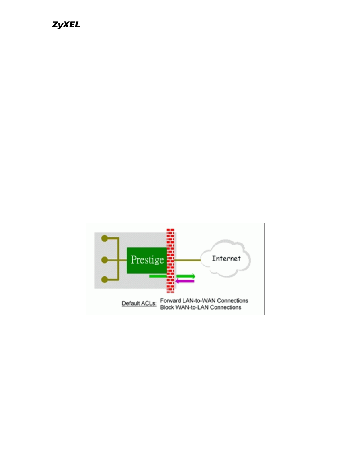
13. What are the default ACL firewall rules in P-202H Plus v2?
There are two default ACLs pre-configured in the P-202H Plus v2, one allows all
connections from LAN to WAN and the other blocks all connections from WAN to
LAN except of the DHCP packets.
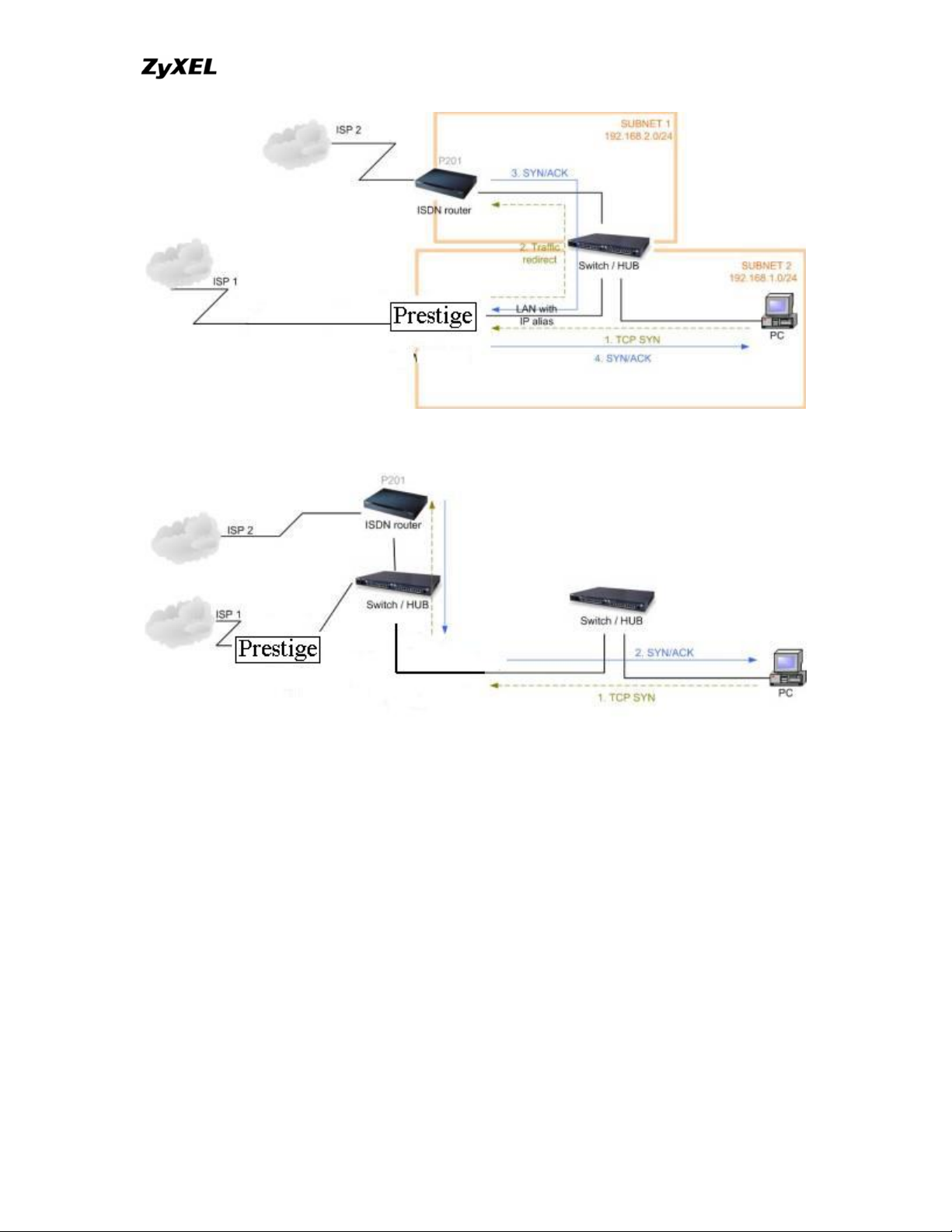
14. Why static/policy route be blocked by P-202H Plus v2?
P-202H Plus v2 is an ideal secure gateway for all data passing between the
Internet and the LAN/DMZ. For some reasons (load balance or backup line),
users may want traffic to be re-routed to another Internet access devices while
still be protected by P-202H Plus v2. In such case, the network topology is the
most important issue. Here is a common example that people mis-deploy the
static route.
All contents copyright © 2006 ZyXEL Communications Corporation.
20
Page 21

P-202H Plus v2 Support Notes
The above figure indicates the "triangle route" topology. It works fine if you turn
off firewall function on P-202H Plus v2 box. However, if you turn on firewall, your
connection will be blocked by firewall because of the following reason.
Step 1. Being the default gateway of PC, P-202H Plus v2 will receive all
"outgoing" traffic from PC.
Step 2. And because of Static route/Policy Routing, P-202H Plus v2
forwards the traffic to another gateway (ISDN/Router) which is in the
same segment as P-202H Plus v2's LAN.
Step 3. However the return traffic won't go back to P-202H Plus v2, in stead,
the "another gateway (ISDN/Router)" will send back the traffic to PC
directly. Because the gateway (say, P201) and the PC are in the same
segment.
When firewall is turned on, P-202H Plus v2 will check the outgoing traffic by ACL
and create dynamic sessions to allow return traffic to go back. To achieve AntiDoS, P-202H Plus v2 will send RST packets to the PC and the peer since it
never receives the TCP SYN/ACK packet. Thus the connection will always be
reset by P-202H Plus v2.
Solutions.
(A) Deploying your second gateway in IP alias segment is a better solution. In
this way, your connection can be always under control of firewall. And thus there
won't be Triangle Route problem.
All contents copyright © 2006 ZyXEL Communications Corporation.
21
Page 22
P-202H Plus v2 Support Notes
(B) Deploying your second gateway on WAN side.
(C) To resolve this conflict, we add an option for users to allow/disallow such
Triangle Route topology in both CI command and Web configurator . You can
issue this command, "sys firewall ignore triangle all on" , to allow firewall
bypass triangle route checking. In Web GUI, you can find this option in firewall
setup page.
But we would like to notify that if you allow Triangle Route, any traffic will
be easily injected into the protected network through the unprotected
gateway. In fact, it's a security hole in protected your network.
Configuration
1. How do I configure the firewall?
P-202H Plus v2 supports a embedded web server so that you can use the web
brower to configure it from any OS platform.
All contents copyright © 2006 ZyXEL Communications Corporation.
22
Page 23

P-202H Plus v2 Support Notes
2. How do I prevent others from configuring my firewall?
There are several ways to protect others from touching the settings of your
firewall.
1. Change the default password since it is required when setting up the
firewall using Telnet, Console or Web browser.
2. Limit who can Telnet to your router. You can enter the IP address of the
secured LAN host in SMT Menu 24.11 to allow Telnet to your P-202H Plus
v2. The default value in this field is 0.0.0.0, which means you do not care
which host is trying to Telnet your P-202H Plus v2.
3. Can I use a browser to configure my P-202H Plus v2?
Yes, you can use a web browser to configure the P-202H Plus v2.
4. Why can't I configure my router using Telnet over WAN?
There are three reasons that Telnet from WAN is blocked.
1. When the firewall is turned on, all connections from WAN to LAN are
blocked by the default ACL rule. To enable Telnet from WAN, you must
turn the firewall off (Menu 21.2) or create a firewall rule to allow Telnet
connection from WAN. The WAN-to-LAN ACL summary will look like as
shown below.
Source IP= Telnet host
Destination IP= router' WAN IP
Service= TCP/23
Action=Forward
2. You have disabled Telnet service in Menu 24.11.
3. Telnet service is enabled but your host IP is not the secured host entered
in Menu 24.11. In this case, the error message 'Client IP is not allowed!'
is appeared on the Telnet screen.
4. The default filter rule 3 (Telnet_FTP_WAN) is applied in the Input Protocol
field in menu 11.5.
5. The console port is in use.
5. Why can't I upload the firmware and configuration file using FTP over
WAN?
1. When the firewall is turned on, all connections from WAN to LAN are
blocked by the default ACL rule. To enable FTP from WAN, you must turn the
All contents copyright © 2006 ZyXEL Communications Corporation.
23
Page 24

P-202H Plus v2 Support Notes
firewall off (Menu 21.2) or create a firewall rule to allow FTP connection from
WAN. The WAN-to-LAN ACL summary will look like as shown below.
Source IP= FTP host
Destination IP= P-202H Plus v2's WAN IP
Service= FTP TCP/21, TCP/20
Action=Forward
2. You have disabled FTP service in Menu 24.11.
3. The default filter rule 3 (Telnet_FTP_WAN) is applied in the Input Protocol
field in menu 11.5.
6. Why can't I configure my router using Telnet over LAN?
1. You have disabled Telnet service in Menu 24.11.
2. Telnet service is enabled but your host IP is not the secured host entered
in Menu 24.11. In this case, the error message 'Client IP is not allowed!'
is appeared on the Telnet screen.
3. The default filter rule 3 (Telnet_FTP_LAN) is applied in the Input Protocol
field in menu 3.1.
4. The console port is in use.
7. Why can't I upload the firmware and configuration file using FTP over
LAN?
1. 1. You have disabled FTP service in Menu 24.11.
2. The default filter rule 3 (Telnet_FTP_LAN) is applied in the Input Protocol
field in menu 3.1.
Log and alert
1. When does the P-202H Plus v2 generate the firewall log?
The P-202H Plus v2 generates the log immediately when the packet match,
doesn't match (or both) a firewall rule. The log for Default Permit (LAN to WAN,
WAN to LAN) is generated automatically. To generate the log for custom rules,
the Log option in Web Configurator must be set to Not Match, Match, or Both.
The Reason column for the default permit shown in the log will be 'default
permit, <1, 00> or <2, 00>'. Here <1, 00> means the LAN-to-WAN default ACL
set, <2, 00> means the WAN-to-LAN default ACL set.
2. What does the log show to us?
All contents copyright © 2006 ZyXEL Communications Corporation.
24
Page 25

P-202H Plus v2 Support Notes
The log supports up to 128 entries. There are 2 rows and 5 columns for each
entry. Please see the example shown below.
# Time Packet Information Reason Action
127|Mar 15 0 |From:192.168.1.34 To:202.132.155.93 |default permit |forward
| 03:03:54|ICMP type:00008 code:00000 |<1,00> |
Where <X,Y> stands for <Set number, Rule number>. X=1,2 ; Y=00~10. There
are two policy sets, set 1 for rules checking connections from LAN to WAN and
set 2 for rules checking connections from WAN to LAN. So, X=1 means set 1 and
X=2 means set 2.
Y means the rule in the set. Because we can configure up to 10 rules in a set, so
Y can be from 1 to 10. If the rule number shows 00, it means the Default Rule.
3. How do I view the firewall log?
The log keeps 128 entries, the new entries will overwrite the old entries when the
log has over 128 entries.
There are three ways to view the firewall log:
1. View the log from SMT Menu 21.3-View Firewall Log
2. View the log using CI command-sys firewall display
3. View the log from Web Configurator
4. When does the P-202H Plus v2 generate the firewall alert?
The P-202H Plus v2 generates the alert when an attack is detected by the
firewall and sends it via Email. So, to send the alert you must configure the mail
server and Email address using Web Configurator. You can also specify how
frequently you want to receive the alert via Web Configurator.
5. What does the alert show to us?
The alert shown in the Email is actually the evens of the attack. So, the Reason
column shows Attack and the attack type. Please see the example shown
below.
# Time Packet Information Reason Action
127|Mar 15 0 |From:192.168.1.1 To:192.168.1.1 |attack |block
| 03:04:54|ICMP type:00008 code:00000 |land |
All contents copyright © 2006 ZyXEL Communications Corporation.
25
Page 26

P-202H Plus v2 Support Notes
6. What is the difference between the log and alert?
A log entry is just added to the log inside the P-202H Plus v2 and e-mailed
together with all other log entries at the scheduled time as configured. An alert is
e-mailed immediately after an attacked is detected.
All contents copyright © 2006 ZyXEL Communications Corporation.
26
Page 27

P-202H Plus v2 Support Notes
IPSec Related FAQ
IPSec FAQ
VPN Overview
1. What is VPN?
A VPN gives users a secure link to access corporate network over the Internet or
other public or private networks without the expense of lease lines. A secure
VPN is a combination of tunneling, encryption, authentication, access control and
auditing technologies/services used to transport traffic over the Internet or any
insecure network that uses the TCP/IP protocol suite for communication.
2. Why do I need VPN?
There are some reasons to use a VPN. The most common reasons are because
of security and cost.
Security
1). Authentication
With authentication, VPN receiver can verify the source of packets and
guarantee the data integrity.
2). Encryption
With encryption, VPN guarantees the confidentiality of the original user data.
Cost
1). Cut long distance phone charges
Because users typically dial the their local ISP for VPN, thus, long distance
phone charge is reduced than making a long direct connection to the remote
office.
2).Reducing number of access lines
Many companies pay monthly charges for two types access lines: (1) high-speed
links for their Internet access and (2) frame relay, ISDN Primary Rate Interface or
T1 lines to carry data. A VPN may allow a company to carry the data traffic over
its Internet access lines, thus reducing the need for some installed lines.
All contents copyright © 2006 ZyXEL Communications Corporation.
27
Page 28

P-202H Plus v2 Support Notes
3. What are most common VPN protocols?
There are currently three major tunneling protocols for VPNs. They are Point-toPoint Tunneling Protocol (PPTP), Layer 2 Tunneling Protocol (L2TP) and Internet
Protocol Security (IPSec).
4. What is PPTP?
PPTP is a tunneling protocol defined by the PPTP forum that allows PPP packets
to be encapsulated within Internet Protocol (IP) packets and forwarded over any
IP network, including the Internet itself. The PPTP is supported in Windows NT
and Windows 98 already. For Windows 95, it needs to be upgraded by the DialUp Networking 1.2 upgrade.
5. What is L2TP?
Layer Two Tunneling Protocol (L2TP) is an extension of the Point-to-Point
Tunneling Protocol (PPTP) used by an Internet service provider (ISP) to enable
the operation of a virtual private network (VPN) over the Internet.
6. What is IPSec?
IPSec is a set of IP extensions developed by IETF (Internet Engineering Task
Force) to provide security services compatible with the existing IP standard
(IPv.4) and also the upcoming one (IPv.6). In addition, IPSec can protect any
protocol that runs on top of IP, for instance TCP, UDP, and ICMP. The IPSec
provides cryptographic security services. These services allow for authentication,
integrity, access control, and confidentiality. IPSec allows for the information
exchanged between remote sites to be encrypted and verified. You can create
encrypted tunnels (VPNs), or just do encryption between computers. Since you
have so many options, IPSec is truly the most extensible and complete network
security solution.
7. What secure protocols does IPSec support?
There are two protocols provided by IPSec, they are AH (Authentication Header,
protocol number 51) and ESP (Encapsulated Security Payload, protocol number
50).
8. What are the differences between 'Transport mode' and 'Tunnel mode?
The IPSec protocols (AH and ESP) can be used to protect either an entire IP
payload or only the upper-layer protocols of an IP payload. Transport mode is
mainly for an IP host to protect the data generated locally, while tunnel mode is
All contents copyright © 2006 ZyXEL Communications Corporation.
28
Page 29

P-202H Plus v2 Support Notes
for security gateway to provide IPSec service for other machines lacking of IPSec
capability.
In this case, Transport mode only protects the upper-layer protocols of IP
payload (user data). Tunneling mode protects the entire IP payload including
user data.
There is no restriction that the IPSec hosts and the security gateway must be
separate machines. Both IPSec protocols, AH and ESP, can operate in either
transport mode and tunnel mode.
9. What is SA?
A Security Association (SA) is a contract between two parties indicating what
security parameters, such as keys and algorithms they will use.
10. What is IKE?
IKE is short for Internet Key Exchange. Key Management allows you to
determine whether to use IKE (ISAKMP) or manual key configuration to set up a
VPN.
There are two phases in every IKE negotiation- phase 1 (Authentication) and
phase 2 (Key Exchange). Phase 1 establishes an IKE SA and phase 2 uses that
SA to negotiate SAs for IPSec.
11. What is Pre-Shared Key?
A pre-shared key identifies a communicating party during a phase 1 IKE
negotiation. It is called 'Pre-shared' because you have to share it with another
party before you can communicate with them over a secure connection.
12. What are the differences between IKE and manual key VPN?
The only difference between IKE and manual key is how the encryption keys and
SPIs are determined.
• For IKE VPN, the key and SPIs are negotiated from one VPN gateway to
the other. Afterward, two VPN gateways use this negotiated keys and
SPIs to send packets between two networks.
• For manual key VPN, the encryption key, authentication key (if needed),
and SPIs are predetermined by the administrator when configuring the
security association.
All contents copyright © 2006 ZyXEL Communications Corporation.
29
Page 30

P-202H Plus v2 Support Notes
IKE is more secure than manual key, because IKE negotiation can generate new
keys and SPIs randomly for the VPN connection.
P-202H Plus v2 VPN
1. How do I configure P-202H Plus v2 VPN?
You can configure P-202H Plus v2 for VPN using SMT or Web configurator. P202H Plus v2 1 supports Web only.
2. How many VPN connections does P-202H Plus v2 support?
One P-202H Plus v2 202H Plus supports 2 VPN connections.
3. What VPN protocols are supported by P-202H Plus v2 VPN?
All P-202H Plus v2 series support ESP (protocol number 50) and AH (protocol
number 51).
4. What types of encryption does P-202H Plus v2 VPN support?
P-202H Plus v2 supports 56-bit DES and 168-bit 3DES.
5. What types of authentication does P-202H Plus v2 VPN support?
VPN vendors support a number of different authentication methods. P-202H Plus
v2 VPN supports both SHA1 and MD5.
AH provides authentication, integrity, and replay protection (but not
confidentiality). Its main difference with ESP is that AH also secures parts of the
IP header of the packet (like the source/destination addresses), but ESP does
not.
ESP can provide authentication, integrity, replay protection, and confidentiality of
the data (it secures everything in the packet that follows the header). Replay
protection requires authentication and integrity (these two go always together).
Confidentiality
(encryption) can be used with or without authentication/integrity. Similarly, one
could use authentication/integrity with or without confidentiality.
6. I am planning my P-202H Plus v2-to-P-202H Plus v2 VPN configuration.
What do I need to know?
All contents copyright © 2006 ZyXEL Communications Corporation.
30
Page 31

P-202H Plus v2 Support Notes
First of all, both P-202H Plus v2 must have VPN capabilities. Please check the
firmware version, V3.50 or later has the VPN capability.
If your P-202H Plus v2 is capable of VPN, you can find the VPN options in
Advanced>VPN tab.
For configuring a "box-to-box VPN", there are some tips:
1. If there is a NAT router running in the front of P-202H Plus v2, please
make sure the NAT router supports to pass through IPSec.
2. In NAT case (either run on the frond end router, or in P-202H Plus v2 VPN
box), only IPSec ESP tunneling mode is supported since NAT againsts AH
mode.
3. Source IP/Destination IP-- Please do not number the LANs (local and
remote) using the same exact range of private IP addresses. This will
make VPN destination addresses and the local LAN addresses are
indistinguishable, and VPN will not work.
4. Secure Gateway IP Address -- This must be a public, routable IP
address, private IP is not allowed. That means it can not be in the 10.x.x.x
subnet, the 192.168.x.x subnet, nor in the range 172.16.0.0 -
172.31.255.255 (these address ranges are reserved by internet standard
for private LAN numberings behind NAT devices). It is usually a static IP
so that we can pre-configure it in P-202H Plus v2 for making VPN
connections. If it is a dynamic IP given by ISP, you still can configure this
IP address after the remote P-202H Plus v2 is on-line and its WAN IP is
available from ISP.
7. Does P-202H Plus v2 support dynamic secure gateway IP?
If the remote VPN gateways uses dynamic IP, we enter 0.0.0.0 as the Secure
Gateway IP Address in P-202H Plus v2. In this case, the VPN connection can
only be initiated from dynamic side to fixed side in order to update its dynamic IP
to the fixed side. However, if both gateways use dynamic IP addresses, it is no
way to establish VPN connection at all.
8. What VPN gateway that has been tested with P-202H Plus v2
successfully?
We have tested P-202H Plus v2 successfully with the following third party VPN
gateways.
• Cisco 1720 Router, IOS 12.2(2)XH, IP/ADSL /FW/IDS PLUS IPSEC 3DES
• NetScreen 5, ScreenOS 2.6.0r6
• SonicWALL SOHO 2
• WatchGuard Firebox II
All contents copyright © 2006 ZyXEL Communications Corporation.
31
Page 32

P-202H Plus v2 Support Notes
• ZyXEL P-202H Plus v2
• Avaya VPN
• Netopia VPN
• III VPN
9. What VPN software that has been tested with P-202H Plus v2
successfully?
We have tested P-202H Plus v2 successfully with the following third party VPN
software.
• SafeNet Soft-PK, 3DES edition
• Checkpoint Software
• SSH Sentinel, 1.4
• SecGo IPSec for Windows
• F-Secure IPSec for Windows
• KAME IPSec for UNIX
• Nortel IPSec for UNIX
• Intel VPN, v. 6.90
• FreeS/WAN for Linux
• SSH Remote ISAKMP Testing Page, (http://isakmp-test.ssh.fi/cgi-bin/nph-
isakmp-test)
• Windows 2000, IPSec
10.Will ZyXEL support Secure Remote Management?
Yes, we will support it and we are working on it currently.
11. Does P-202H Plus v2 VPN support NetBIOS broadcast?
The current 3.40 firmware release does not support it. But it is in our wish list.
12. What are the difference between the 'My IP Address' and 'Secure
Gateway IP Address' in Menu 27.1.1?
'My IP Adderss' is the Internet IP address of the local P-202H Plus v2. The
'Secure Gateway IP Address' is the Internet IP address of the remote IPSec
gateway.
13. Is the host behind NAT allowed to use IPSec?
NAT Condition Supported IPSec Protocol
VPN Gateway embedded
NAT
AH tunnel mode, ESP tunnel
mode
VPN client/gateway behind ESP tunnel mode
All contents copyright © 2006 ZyXEL Communications Corporation.
32
Page 33

P-202H Plus v2 Support Notes
*
NAT
NAT in Transport mode None
* The NAT router must support IPSec pass through. For example, for P-202H
Plus v2 SUA/NAT routers, IPSec pass through is supported since ZyNOS 3.21.
The default port and the client IP have to be specified in menu 15-SUA Server
Setup.
14. Why does VPN throughput decrease when staying in SMT menu 24.1?
If P-202H Plus v2 stays in menu 24.1, 24.8 and 27.3 a certain of memory is
allocated to generate the required statistics. So, we do not suggest to stay in
menu 24.1, 27.3 and 24.8 when VPN is in use.
15. How do I configure P-202H Plus v2 with NAT for internal servers?
Generally, without IPSec, to configure an internal server for outside access, we
need to configure the server private IP and its service port in SUA/NAT Server
Table.
However, if both NAT and IPSec is enabled in P-202H Plus v2, the edit of the
table is necessary only if the connection is a non-secure connections. For secure
connections, none SUA server settings are required since private IP is reachable
in the VPN case.
For example:
host-----------P-202H Plus v2(NAT)-----------------Internet----Secure host
\
\
Non-secure host
SSH Sentinel FAQ
All contents copyright © 2006 ZyXEL Communications Corporation.
33
Page 34

P-202H Plus v2 Support Notes
1. What is SSH Sentinel VPN client?
Developed by SSH (http://www.ssh.com) Sentinel VPN client is a bundled
software with P-202H Plus v2 VPN solution. It supports IPSec/VPN.
2. Why do I need to use Sentinel?
SSH Sentinel(TM) is an easy-to-use software for remote working based on the
latest VPN technology. The software provides smooth integration with P-202H
Plus v2 VPN which may be installed in HQ gateway.
3. Does SSH Sentinel work with the PPP over Ethernet (PPPoE) protocol,
which is used by the ADSL Network Adapter cards?
Yes, the latest release SSH Sentinel 1.3, also supports PPPoE, but due to the
wide range of PPPoE implementations and the fact, that we have a very limited
access to PPPoE adapters in general, we are not able to fully test this
functionality.
As a consequence, it is hard to say with exactly which PPPoE drivers SSH
Sentinel 1.3 is fully compatible.
4. How to configure Pre-IPSec filter?
In pre-ipsec configuration, never, remove the pre-IPSec filter rule that bypasses
IKE traffic. If you do, all your attempts to establish any IPSec connection are
bound to fail, because the negotiations never take place. Only when you would
like to have some TCP/UDP packets bypass IPSec, must you specify the traffic
as bypass in pre-ipsec filter. Otherwise, just not setup any bypass/discard/reject
on the traffic you would like to be protected by IPSec.
5. What is "Acquire virtual IP address" for? Should I check this box?
With this feature, Sentinel can obtain a virtual IP address assigned from VPN
gateway. However, if connecting with P-202H Plus v2, please not check this box.
P-202H Plus v2 doesn’t support this feature in current firmware.
6. What is "Extended Authentication"? Should I check this box?
With this feature, VPN connection from Sentinel can be authenticated to
authentication server, such as, RADIUS, TACAS, …etc. behind remote VPN
gateway. However, if connecting with P-202H Plus v2, please not check this box.
P-202H Plus v2 doesn’t support this feature in current firmware. It will support in
the near future.
All contents copyright © 2006 ZyXEL Communications Corporation.
34
Page 35

P-202H Plus v2 Support Notes
7. Does Sentinel support IP range?
No, only subnet/single is supported. So when connecting with P-202H Plus v2,
please not use range as address type.
8. Does Sentinel support 2 VPN connections at the same time?
No, Sentinel doesn’t support it. Only one VPN connection can be activated at the
same time.
9. What is this option, “Attach the selected values to proposal only” for?
To increase compatibility, Sentinel sends many kinds of possible proposal for it’s
peer side, say P-202H Plus v2 to choose. If you uncheck this option, Sentinel will
only send out the proposal you configured. To decrease negotiation time, you
can uncheck this option, and verify phase1/phase2 parameters are consistent on
both sides.
10. How to initiate a VPN tunnel from Sentinel?
Right click SSH icon in system tray, click the VPN connection you have setup in
Select VPN. Packets triggering doesn't work in this case.
11. Can P-202H Plus v2 be the initiator of VPN tunnel to Sentinel?
No. Sentinel is supposed to be a VPN solution for remote access. Please always
initiate your VPN tunnel from Sentinel but not from P-202H Plus v2.
12. How can I verify if the VPN connection is up in Sentinel?
You can check if your VPN connection is up by double clicking SSH icon in
system tray. If the connection is up, you should see your VPN network in the
popped out window.
13. I am using EnterNet 300, a PPPoE dial up software. Any concern?
If using EnterNet PPP over Ethernet client, the network access type must be set
from the client’s advanced connection settings to protocol driver. Open Enternet
300 Profiles window -> Connections -> Settings -> Advanced -> In Network
Access section choose Protocol Driver.
Application Notes
All contents copyright © 2006 ZyXEL Communications Corporation.
35
Page 36

P-202H Plus v2 Support Notes
General Application Notes
1. Internet Access
A typical Internet access application of the P-202H Plus v2 is shown below. For a
small office, there are some components you need to check before accessing the
Internet.
• Before you begin
The P-202H Plus v2 is shipped with the following factory default:
1. IP address = 192.168.1.1, subnet mask = 255.255.255.0 (24 bits)
2. DHCP server enabled with IP pool starting from 192.168.1.33
3. Default SMT menu password = 1234
• Setting up the Win95/98 Workstation
1. Ethernet connection
All PCs must have an Ethernet adapter card installed.
• If you only have one PC, connect the PC's Ethernet adapter to the P-202H
Plus v2's LAN port with a crossover (red one) Ethernet cable.
• If you have more than one PC, both the PC's Ethernet adapters and the P-
202H Plus v2's LAN port must be connected to an external hub with
straight Ethernet cable.
2. TCP/IP Installation
You must first install TCP/IP software on each PC before you can use it for
Internet access. If you have already installed TCP/IP, go to the next section to
configure it; otherwise, follow these steps to install:
• In the Control Panel/Network window, click Add button.
• In the Select Network Component Type windows, select Protocol and
click Add.
• In the Select Network Protocol windows, select Microsoft from the
manufacturers, then select TCP/IP from the Network Protocols and click
OK.
3. TCP/IP Configuration
Follow these steps to configure Windows TCP/IP:
All contents copyright © 2006 ZyXEL Communications Corporation.
36
Page 37

P-202H Plus v2 Support Notes
• In the Control Panel/Network window, click the TCP/IP entry to select it
and click Properties button.
• In the TCP/IP Properties window, select Obtain an IP address
automatically.
Note: Do not assign arbitrary IP address and subnet mask to your PCs,
otherwise, you will not be able to access the Internet.
• Click the WINS configuration tab and select Disable WINS Resolution.
• Click the Gateway tab. Highlight any installed gateways and click the
Remove button until there are none listed.
• Click the DNS Configuration tab and select Disable DNS.
• Click OK to save and close the TCP/IP properties window
• Click OK to close the Network window. You will be prompted to insert your
Windows CD or disk. When the drivers are updated, you will be asked if
you want to restart the PC. Make sure your P-202H Plus v2 is powered on
before answering Yes to the prompt. Repeat the above steps for each
Windows PC on your network.
• Setting up the P-202H Plus v2 router
The following procedure is for the most typical usage of the P-202H Plus v2
where you have a single-user account (SUA). The PNC (P-202H Plus v2
Network Commander) is a Windows-based tool that helps you to easily configure
your P-202H Plus v2 for Internet access. It is included in the P-202H Plus v2
package. Please install the PNC first before configuring your P-202H Plus v2.
All contents copyright © 2006 ZyXEL Communications Corporation.
37
Page 38

Example:
P-202H Plus v2 Support Notes
Key Settings:
• Pri Phone#= is the phone number your P-202H Plus v2 has to dial in order
to access your ISP.
• My Login and My Password are the login information provided by ISP.
• Since you have a single user Internet account, Single User Account
should be set to 'Yes'.
• For the Local IP Address field, since the IP address will be dynamically
assigned, you can either enter '0.0.0.0' or you can leave this field blank
After saving this menu, you will be asked if you want to perform an Internet
connection test. Select 'Yes' to perform the test. If the test fails, please check
again the above settings or refer to the User's Manual Troubleshooting section
for correction action.
When you have configured and saved Menu 4, you should see that you have
created a remote node in Menu 11. You can perform more advanced
configuration options to this remote node in this menu.
2. SUA Applications
All contents copyright © 2006 ZyXEL Communications Corporation.
38
Page 39

P-202H Plus v2 Support Notes
Configure a PPTP server behind SUA
• Introduction
PPTP is a tunneling protocol defined by the PPTP forum that allows PPP packets
to be encapsulated within Internet Protocol (IP) packets and forwarded over any
IP network, including the Internet itself.
In order to run the Windows9x PPTP client, you must be able to establish an IP
connection with a tunnel server such as the Windows NT Server 4.0 Remote
Access Server.
Windows Dial-Up Networking uses the Internet standard Point-to-Point (PPP) to
provide a secure,optimized multiple-protocol network connection over dial-up
telephone lines. All data sent over this connection can be encrypted and
compressed, and multiple network level protocols (TCP/IP, NetBEUI and IPX)
can be run correctly. Windows NT Domain Login level security is preserved even
across the Internet.
Window95 PPTP Client / Internet / NT RAS Server Protocol Stack
PPTP appears as new modem type (Virtual Private Networking Adapter) that
can be selected when setting up a connection in the Dial-Up Networking folder.
The VPN Adapter type does not appear elsewhere in the system. Since PPTP
encapsulates its data stream in the PPP protocol, the VPN requires a second
dial-up adapter. This second dial-up adapter for VPN is added during the
installation phase of the Upgrade in addition to the first dial-up adapter that
provides PPP support for the analog or ISDN modem.
All contents copyright © 2006 ZyXEL Communications Corporation.
39
Page 40

P-202H Plus v2 Support Notes
The PPTP is supported in Windows NT and Windows 98 already. For Windows
95, it needs to be upgraded by the Dial-Up Networking 1.2 upgrade.
• Configuration
This application note explains how to establish a PPTP connection with a remote
private network in the P-202H Plus v2 SUA case. In ZyNOS, all PPTP packets
can be forwarded to the internal PPTP Server (WinNT server) behind SUA. The
port number of the PPTP has to be entered in the SMT Menu 15 for P-202H Plus
v2 to forward to the appropriate private IP address of Windows NT server.
• Example
The following example shows how to dial to an ISP via the P-202H Plus v2 and
then establish a tunnel to a private network. There will be three items that you
need to set up for PPTP application, these are PPTP server (WinNT), PPTP
client (Win9x) and the P-202H Plus v2.
o PPTP server setup (WinNT)
Add the VPN service from Control Panel>Network
Add an user account for PPTP logged on user
Enable RAS port
Select the network protocols from RAS such as IPX, TCP/IP
NetBEUI
Set the Internet gateway to P-202H Plus v2
o PPTP client setup (Win9x)
Add one VPN connection from Dial-Up Networking by
entering the correct username & password and the IP
address of the P-202H Plus v2's Internet IP address for
logging to NT RAS server.
All contents copyright © 2006 ZyXEL Communications Corporation.
40
Page 41

P-202H Plus v2 Support Notes
Set the Internet gateway to the router that is connecting to
ISP
o P-202H Plus v2 router setup
• Before making a VPN connection from Win9x to WinNT server, you need
to connect P-202H Plus v2 router to your ISP first.
• Enter the IP address of the PPTP server (WinNT server) and the port
number for PPTP as shown below.
When you have finished the above settings, you can ping to the remote
Win9x client from WinNT. This ping command is used to demonstrate that
remote the Win9x can be reached across the Internet. If the Internet
connection between two LANs is achive, you can place a VPN call from
the remote Win9x client.
For example:
C:\ping 203.66.113.2
When a dial-up connection to ISP is established, a default gateway is
assigned to the router traffic through that connection. Therefore, the
output below shows the default gateway of the Win95 client after the dialup connection has been established.
Before making a VPN connection from the Win9x client to the NT server,
you need to know the exact Internet IP address that the ISP assigns to P-
All contents copyright © 2006 ZyXEL Communications Corporation.
41
Page 42

P-202H Plus v2 Support Notes
202H Plus v2 router in SUA mode and enter this IP address in the VPN
dial-up dialog box. You can check this Internet IP address from PNC
Monitor or SMT Menu 24.1. If the Internet IP address is a fixed IP address
provided by ISP in SUA mode, then you can always use this IP address
for reaching the VPN server.
In the following example, the IP address '140.113.1.225' is dynamically
assigned by ISP. You must enter this IP address in the 'VPN Server'
dialog box for reaching the PPTP server. After the VPN link is established,
you can start the network protocol application such as IP, IPX and
NetBEUI.
Configure an Internal Server Behind SUA
• Introduction
All contents copyright © 2006 ZyXEL Communications Corporation.
42
Page 43

P-202H Plus v2 Support Notes
If you wish, you can make internal servers (e.g., Web, ftp or mail server)
accessible for outside users, even though SUA makes your LAN appear as a
single machine to the outside world. A service is identified by the port number.
Also, since you need to specify the IP address of a server in the P-202H Plus v2,
a server must have a fixed IP address and not be a DHCP client whose IP
address potentially changes each time it is powered on.
In addition to the servers for specific services, SUA supports a default server. A
service request that does not have a server explicitly designated for it is
forwarded to the default server. If the default server is not defined, the service
request is simply discarded.
• Configuration
To make a server visible to the outside world, specify the port number of the
service and the inside address of the server in 'Menu 15', Multiple Server
Configuration. The outside users can access the local server using the P-202H
Plus v2's WAN IP address which can be obtained from menu 24.1.
• For example (Configuring an internal Web server for outside access) :
• Port numbers for some services
Service Port Number
FTP 21
All contents copyright © 2006 ZyXEL Communications Corporation.
43
Page 44

P-202H Plus v2 Support Notes
Telnet 23
SMTP 25
DNS (Domain Name Server) 53
www-http (Web) 80
Tested SUA Applications (e.g., Cu-SeeMe, ICQ, NetMeeting)
• Introduction
Generally, SUA makes your LAN appear as a single machine to the outside
world. LAN users are invisible to outside users. However, some applications such
as Cu-SeeMe, and ICQ will need to connect to the local user behind the P-202H
Plus v2. In such case, a SUA server must be entered in menu 15 to forward the
incoming packets to the true destination behind SUA. Generally, we do not need
extra settings of menu 15 for an outgoing connection. But for some applications
we need to configure the menu 15 to make the outgoing connection work. After
the required menu 15 settings are completed the internal server or client
applications can be accessed by using the P-202H Plus v2's WAN IP address.
• SUA Supporting Table
The following are the required menu 15 settings for the various applications
running SUA mode.
ZyXEL SUA Supporting Table
1
All contents copyright © 2006 ZyXEL Communications Corporation.
44
Page 45

P-202H Plus v2 Support Notes
Required Settings in Menu 15
Application
Outgoing Connection
Port/IP
Incoming
Connection
HTTP None 80/client IP
FTP None 21/client IP
TELNET None 23/client IP
(and remove Telnet
filter in WAN port)
POP3 None 110/clinet IP
SMTP None 25/client IP
None for Chat.
mIRC
For DCC, please set
.
Default/Client IP
Windows PPTP None 1723/client IP
ICQ 99a None for Chat.
Default/client IP
For DCC, please set:
ICQ -> preference ->
connections -> firewall and
set the firewall time out to
80 seconds in firewall
setting.
Cornell 1.1 Cu-SeeMe None 7648/client IP
White Pine 3.1.2 Cu-SeeMe 7648/client IP &
Default/client IP
24032/client IP
White Pine 4.0 Cu-SeeMe 7648/client IP &
Default/client IP
24032/client IP
Microsoft NetMeeting 2.1 &
2.11
None 1720/client IP
1503/client IP
Cisco IP/TV 2.0.0 None .
RealPlayer G2 None .
VDOLive None .
Quake1.06
QuakeII2.30
4
5
None Default/client IP
None Default/client IP
QuakeIII1.05 beta None .
StartCraft. 6112/client IP .
Quick Time 4.0 None .
All contents copyright © 2006 ZyXEL Communications Corporation.
45
Page 46

P-202H Plus v2 Support Notes
5631/client IP
pcAnywhere 8.0 None
5632/client IP
22/client IP
1
Since SUA enables your LAN to appear as a single computer to the Internet, it
is not possible to configure similar servers on the same LAN behind SUA.
2
Because White Pine Cu-SeeMe uses dedicate ports (port 7648 & port 24032) to
transmit and receive data, therefore only one local Cu-SeeMe is allowed within
the same LAN.
3
With SUA enabled, NetMeeting users within the same LAN will not be able to
connect to the remote NetMeeting user, and as remote users are not able to
distinguish between local users with the same internet IP and SUA allows one
local NetMeeting user to connect to multiple Internet users at the same time.
4
Certain Quake servers do not allow multiple users to login using the same
unique IP, so only one Quake user will be allowed in this case. Moreover, when a
Quake server is configured behind SUA, P-202H Plus v2 will not be able to
provide information of that server on the internet.
5
Quake II has the same limitations as that of Quake I.
Notes
1. If a SMTP (port 25) server is configured in menu 15 the POP3 ( port 110)
packets will also be forwarded to the same SMTP server by the P-202H
Plus v2 automatically. There is no need to configure additional POP3
server in menu 15. Two ports (25 & 110) must be configured in menu 15
to support both SMTP and POP3 services.
2. NetMeeting, RealPlayer, IP/TV and Quick Time are supported.
Configurations
For example, if the workstation operating Cu-SeeMe has an IP of 192.168.1.34,
then the default SUA server must be set to 192.168.1.34. The peer Cu-SeeMe
user can reach this workstation by using P-202H Plus v2's WAN IP address
which can be obtained from menu 24.1.
All contents copyright © 2006 ZyXEL Communications Corporation.
46
Page 47

P-202H Plus v2 Support Notes
3. LAN to LAN
IP Connection
• Introduction
This configuration note explains how to set up two P-202H Plus v2 routers for a
LAN-to-LAN connection. Once the connection is established, the workstations on
both LANs will be able to perform any TCP/IP applications (e.g., FTP, Telnet,
etc.). There will be three items that you need to set up. These are workstation
and the two P-202H Plus v2 routers.
• Configuration
• Setting up the workstation on both LANs
To set up the workstations, you will need to set the following parameters:
All contents copyright © 2006 ZyXEL Communications Corporation.
47
Page 48

P-202H Plus v2 Support Notes
o IP Address-the IP address assigned to the workstation itself
o Subnet Mask-the subnet mask used for your network. Class C
networks generally use a 24-bit netmask DNS (Domain Name
Server) Address-enter the IP address of the DNS server
o Default Gateway-the IP address of the P-202H Plus v2, the default
gateway for LAN1 is P-202H Plus v2 1 and for LAN2 is P-202H
Plus v2 2.
The procedure for configuring these parameters for the workstations may differ
depending on the type of TCP/IP networking software you are using on your
workstations. If you are unfamiliar with how to set these parameters, you can
refer to the technical notes corresponding to your software.
For Windows 9x, please go to 'Win9x>Control Panel>Network>TCP/IP-Network
Adapter' for finishing the above settings.
• Setting up the P-202H Plus v2 1 & P-202H Plus v2 2
Before configuring the two remote nodes for this application, you need to
complete the following settings first in each P-202H Plus v2.
o General Setup in SMT Menu 1-enter the system information.
o ISDN Setup in SMT Menu 2- configure the ISDN parameters.
o Ethernet Setup in SMT Menu 3-enter the IP address of the P-202H
Plus v2 and enable the DHCP server if it is required.
o Remote Node Setup in SMT Menu 11
• P-202H Plus v2 1 Setup
1. Ethernet Setup in SMT Menu 3
Menu 3.2 - TCP/IP and DHCP Ethernet Setup
DHCP Setup:
DHCP= None
Client IP Pool Starting Address= N/A
Size of Client IP Pool= N/A
Primary DNS Server= N/A
Secondary DNS Server= N/A
TCP/IP Setup:
IP Address= 202.113.5.1
IP Subnet Mask= 255.255.255.0
RIP Direction= Both
All contents copyright © 2006 ZyXEL Communications Corporation.
48
Page 49

P-202H Plus v2 Support Notes
Version= RIP-2B
Edit IP Alias= No
2. Remote Node Setup in SMT Menu 11
Menu 11.1 - Remote Node Profile
Rem Node Name= LAN2 Edit PPP Options= No
Active= Yes Rem IP Addr= 203.66.113.1
Call Direction= Outgoing Edit IP= No
Incoming: Telco Option:
Rem Login= Transfer Type= 64K
Rem Password= Allocated Budget(min)=
Rem CLID= N/A Period(hr)=
Call Back= N/A Schedules=
Outgoing: Carrier Access Code=
My Login= test Nailed-Up Connection= No
My Password= ******** Toll Period(sec)= 0
Authen= CHAP/PAP Session Options:
Pri Phone #= 5007025 Edit Filter Sets= No
Sec Phone #= Idle Timeout(sec)= 100
Press ENTER to Confirm or ESC to Cancel:
Key Settings:
o Select the 'Active' field to 'Yes'
o Select the 'Call Direction' to 'Outgoing'
o Enter the correct node account in 'My Login' and 'My Password'
fields
o Enter the phone number of the remote router in the 'Pri Phone #'
field
o Enter the IP address of the remote router in 'Rem IP Addr' field
o Enter the idle timer in the 'Idle Timeout' field for dropping the call if
there is no data traffic between the two remote nodes
• P-202H Plus v2 2 Setup
1. Ethernet Setup in SMT Menu 3
All contents copyright © 2006 ZyXEL Communications Corporation.
49
Page 50

P-202H Plus v2 Support Notes
Menu 3.2 - TCP/IP and DHCP Ethernet Setup
DHCP Setup:
DHCP= None
Client IP Pool Starting Address= N/A
Size of Client IP Pool= N/A
Primary DNS Server= N/A
Secondary DNS Server= N/A
TCP/IP Setup:
IP Address= 203.66.113.1
IP Subnet Mask= 255.255.255.0
RIP Direction= Both
Version= RIP-2B
Edit IP Alias= No
2. Remote Node Setup in SMT Menu 11
Menu 11.1 - Remote Node Profile
Rem Node Name= LAN2 Edit PPP Options= No
Active= Yes Rem IP Addr=202.113.5.1
Call Direction= Outgoing Edit IP= No
Incoming: Telco Option:
Rem Login= Transfer Type= 64K
Rem Password= Allocated Budget(min)=
Rem CLID= N/A Period(hr)=
Call Back= N/A Schedules=
Outgoing: Carrier Access Code=
My Login= test Nailed-Up Connection= No
My Password= ******** Toll Period(sec)= 0
Authen= CHAP/PAP Session Options:
Pri Phone #= 5007025 Edit Filter Sets= No
Sec Phone #= Idle Timeout(sec)= 100
Press ENTER to Confirm or ESC to Cancel:
All contents copyright © 2006 ZyXEL Communications Corporation.
50
Page 51

P-202H Plus v2 Support Notes
Key Settings:
o Select the 'Active' field to 'Yes'
o Select the 'Call Direction' to 'Incoming'
o Enter the correct node account for the dial-in router in 'Rem Login'
and 'Rem Password' fields
o Enter the IP address of the remote router in 'Rem IP Addr' field.
After you have finished the above settings, you are ready to make a test for this
connection from Menu 24.4.5- 'Manual Call' by entering the node number.
Menu 24.4 - System Maintenance - Diagnostic
ISDN System
1. Hang Up B1 Call 21. Reboot System
2. Hang Up B2 Call 22. Command Mode
3. Reset ISDN
4. ISDN Connection Test
5. Manual Call
TCP/IP
11. Internet Setup Test
12. Ping Host
Enter Menu Selection Number:
Manual Call Remote Node= N/A
Host IP Address= N/A
Configuring for Cisco Mutual Authentication
• Introduction
This configuration note explains what other settings you need to pay attention to
when configuring the P-202H Plus v2 talk to a Cisco router. Due to Cisco's
authentication scheme, you need to configure some additional fields in P-202H
Plus v2 when talking to a Cisco device. There are two things you must pay
attention to. The first is Cisco's mutual authentication scheme, and the second is
their interpretation of CHAP.
All contents copyright © 2006 ZyXEL Communications Corporation.
51
Page 52

P-202H Plus v2 Support Notes
• Configuration
• If the Cisco router requests PAP, you have to configure more settings in
Menu 13 as follows.
Menu 13 - Default Dial-in Setup
Telco Options: IP Address Supplied By:
CLID Authen= None Dial-in User= Yes
IP Pool= No
PPP Options: IP Start Addr= N/A
Recv Authen= CHAP/PAP IP Count(1,4)= N/A
Compression= Yes
Mutual Authen= Yes Session Options:
O/G Username= test Edit Filter Sets= No
O/G Password= ********
Multiple Link Options:
Max Trans Rate(Kbps)= 128
Callback Budget Management:
Allocated Budget(min)= 0
Period(hr)= 0
Press ENTER to Confirm or ESC to Cancel:
Key Settings:
o Set 'Mutual Authen' to 'Yes'
o Set 'PAP Login' to the appropriate login name
o Set 'PAP Password' to the appropriate login password
• If the Cisco route requests CHAP, you have to configure more settings in
Menu 11 as follows.
All contents copyright © 2006 ZyXEL Communications Corporation.
52
Page 53

P-202H Plus v2 Support Notes
Menu 11.1 - Remote Node Profile
Rem Node Name= LAN2 Edit PPP Options= No
Active= Yes Rem IP Addr=140.113.1.1
Call Direction= Both Edit IP= No
Incoming: Telco Option:
Rem Login= [cisco_hostname] Transfer Type= 64K
Rem Password= **** Allocated Budget(min)=
Rem CLID= N/A Period(hr)=
Call Back= N/A Schedules=
Outgoing: Carrier Access Code=
My Login= [P-202H Plus v2_systemname] Nailed-Up Connection= No
My Password= ******** Toll Period(sec)= 0
Authen= CHAP/PAP Session Options:
Pri Phone #= 10000 Edit Filter Sets= No
Sec Phone #= Idle Timeout(sec)= 100
Press ENTER to Confirm or ESC to Cancel:
Key Settings:
o Set 'Incoming: Rem Login' to the 'Cisco device hostname'
o Set 'Incmoing: Rem Password' to be the same as 'Outgoing: My
Password'
o Set 'Outgoing: My Login' to the 'System Name' value in SMT Menu
1
[Note]! The Cisco device must be configured as a remote node but
NOT as a remote user in this case
4. Dial-in User Setup
Using an ISDN TA and Win9x Dial-Up Networking you can dial into P-202H Plus
v2 router with callback and without callback
• Introduction
This configuration note explains how to set up a workstation using an ISDN TA to
connect to the P-202H Plus v2 router. In this configuration, the workstation must
have TCP/IP dial-up program installed such as Windows Dial-up Networking to
make the call. Once the connection is established, the workstation will be able to
All contents copyright © 2006 ZyXEL Communications Corporation.
53
Page 54

P-202H Plus v2 Support Notes
perform any TCP/IP applications (e.g., FTP, Telnet, etc.). There will be two items
that you need to set up for this connection. They are the workstation and the P202H Plus v2 router.
• Configuration
• Setting up the Win9x Dial-Up Networking(DUN)
To set up the DUN for this connection, you will need to set the following
parameters:
o Phone number- the phone number of the P-202H Plus v2 router
o Internet account-Username and Password
o IP Address-the IP address in this case will be dynamically assigned
by the P-202H Plus v2. Generally, you should simply enter 0.0.0.0
into the IP address field.
o DNS (Domain Name Server) Address- the IP address of the DNS
server on the remote LAN.
o Default Gateway-the IP address of the P-202H Plus v2.
Please find the last three settings in Win9x>Dial-Up
Networking>Properties>Server Types>TCP/IP Settings.
• Setting up the P-202H Plus v2
Before configuring the P-202H Plus v2 for this application, you need to first
complete the following settings.
o General Setup in SMT menu 1-enter the system information.
o ISDN Setup in SMT menu 2-Configure the ISDN number
o Ethernet Setup in SMT menu 3-enter the IP address of the P-202H
Plus v2 and enable the DHCP server if it is required.
To setup the P-202H Plus v2 for this application, make sure you have the
following menus configured correctly.
All contents copyright © 2006 ZyXEL Communications Corporation.
54
Page 55

P-202H Plus v2 Support Notes
o Default Dial-in Setup in SMT menu 13
o Edit Dial-in User in SMT menu 14
1. Ethernet Setup in SMT Menu 3
Menu 3.2 - TCP/IP and DHCP Ethernet Setup
DHCP Setup:
DHCP= None
Client IP Pool Starting Address= N/A
Size of Client IP Pool= N/A
Primary DNS Server= N/A
Secondary DNS Server= N/A
TCP/IP Setup:
IP Address= 192.68.135.1
IP Subnet Mask= 255.255.255.0
RIP Direction= Both
Version= RIP-2B
Edit IP Alias= No
2. Default Dial-in Setup in SMT Menu 13
Menu 13 - Default Dial-in Setup
Telco Options: IP Address Supplied By:
CLID Authen= None Dial-in User= No
IP Pool= Yes
PPP Options: IP Start Addr= 192.68.135.10
Recv Authen= CHAP/PAP IP Count(1,4)= 4
Compression= Yes
Mutual Authen= NO Session Options:
O/G Username= N/A Edit Filter Sets= No
O/G Password= N/A
Multiple Link Options:
Max Trans Rate(Kbps)= 128
Callback Budget Management:
All contents copyright © 2006 ZyXEL Communications Corporation.
55
Page 56

P-202H Plus v2 Support Notes
Allocated Budget(min)= 0
Period(hr)= 0
Press ENTER to Confirm or ESC to Cancel:
• The Recv Authen field should be set to the type of authentication protocol
you want to use.
• Since the workstation needs to have its IP address assigned, set the IP
Address Supplied By: Dial-in User field to 'No'.
• Make sure that IP Pool is set to 'Yes'.
• In IP Start Addr, enter the IP address that you want to assign to the
workstation when it dials in. In our example, this would be '192.68.135.10'.
• All the common properties in Menu 13 will be applied to all dial-in users.
Note: If the remote user uses the Win9x to dial in, the Recv Authen must
be set to PAP because Windows 9x will not respond to any periodic CHAP
challenge sent by the P-202H Plus v2 and will cause the P-202H Plus v2
to drop the call.
3. Edit Dial-in User Setup in SMT menu 14.1
• Dial-in user without callback
Menu 14.1 - Edit Dial-in User
User Name= abc
Active= Yes
Passwd= *********
Callback= No
Phone # Supplied by Caller= N/A
Callback Phone #= N/A
Rem CLID=
Idle Timeout= 100
All contents copyright © 2006 ZyXEL Communications Corporation.
56
Page 57

P-202H Plus v2 Support Notes
• The User Name and Password fields should be set to the login username
and password that the workstation will provide when dialing in to the P202H Plus v2. Set the Active field to 'Yes'.
• Dial-in user with callback
Menu 14.1 - Edit Dial-in User
User Name= abc
Active= Yes
Passwd= *********
Callback= Mandatory
Phone # Supplied by Caller= Yes
Callback Phone #= N/A
Rem CLID=
Idle Timeout= 100
• There are two options for the callback, Mandatory and Optional. If the
Mandatory is configured, the P-202H Plus v2 router has to callback
anyway. If the Optional is configured, the dial-in user will have the chance
to cancel the callback.
• The number for calling back to the dial-in user can be specified by the
user during the connection or pre-configured in the Callback Phone #
field of the P-202H Plus v2.
5. Filter
How does ZyXEL filter work?
Conceptually, there are two categories of filter rules: device and protocol. The
Generic filter rules belong to the device category; they act on the raw data
from/to LAN and WAN. The IP and IPX filter rules belong to the protocol category;
they act on the IP and IPX packets.
In order to allow users to specify the local network IP address and port number in
the filter rules with SUA connections, the TCP/IP filter function has to be
executed before SUA for WAN outgoing packets and after the SUA for WAN
incoming IP packets. But at the same time, the Generic filter rules must be
applied at the point when the P-202H Plus v2 is receiving and sending the
packets; i.e. the ISDN interface. So, the execution sequence has to be changed.
The logic flow of the filter is shown in Figure 1 and the sequence of the logic flow
for the packet from LAN to WAN is:
All contents copyright © 2006 ZyXEL Communications Corporation.
57
Page 58

P-202H Plus v2 Support Notes
1. LAN device and protocol input filter sets.
2. WAN protocol call and output filter sets.
3. If SUA is enabled, SUA converts the source IP address from 192.168.1.33
to 203.205.115.6 and port number from 1023 to 4034.
4. WAN device output and call filter sets.
The sequence of the logic flow for the packet from WAN to LAN is:
5. WAN device input filter sets.
6. If SUA is enabled, SUA converts the destination IP address from
203.205.115.6 to 92.168.1.33 and port number from 4034 to 1023.
7. WAN protocol input filter sets.
8. LAN device and protocol output filter sets.
Generic and TCP/IP (and IPX) filter rules are in different filter sets. The SMT will
detect and prevent the mixing of different category rules within any filter set in
Menu 21. In the following example, you will receive an error message 'Protocol
and device filter rules cannot be active together' if you try to activate a
TCP/IP (or IPX) filter rule in a filter set that has already had one or more active
Generic filter rules. You will receive the same error if you try to activate a Generic
filter rule in a filter set that has already had one or more active TCP/IP (or IPX)
filter rules.
Menu 21.1.1:
Menu 21.1.1 - Generic Filter Rule
All contents copyright © 2006 ZyXEL Communications Corporation.
58
Page 59

P-202H Plus v2 Support Notes
Filter #: 1,1
Filter Type= Generic Filter Rule
Active= Yes
Offset= 0
Length= 0
Mask= N/A
Value= N/A
More= No Log= None
Action Matched= Check Next Rule
Action Not Matched= Check Next Rule
Menu 21.1.2:
Menu 21.1.2 - TCP/IP Filter Rule
Filter #: 1,2
Filter Type= TCP/IP Filter Rule
Active= Yes
IP Protocol= 0 IP Source Route= No
Destination: IP Addr= 0.0.0.0
IP Mask= 0.0.0.0
Port #= 0
Port # Comp= None
Source: IP Addr= 0.0.0.0
IP Mask= 0.0.0.0
Port #= 0
Port # Comp= None
TCP Estab= N/A
More= No Log= None
Action Matched= Check Next Rule
Action Not Matched= Check Next Rule
Press ENTER to Confirm or ESC to Cancel:
Saving to ROM. Please wait...
Protocol and device rule cannot be active together
To separate the device and protocol filter categories; two new menus, Menu 11.5
and Menu 13.1, have been added, as well as some changes made to the Menu
3.1, Menu 11.1, and Menu 13. The new fields are shown below.
All contents copyright © 2006 ZyXEL Communications Corporation.
59
Page 60

P-202H Plus v2 Support Notes
Menu 3.1:
Menu 3.1 - General Ethernet Setup
Input Filter Sets:
protocol filters=
device filters=
Output Filter Sets:
protocol filters=
device filters=
Menu 11.1:
Menu 11.1 - Remote Node Profile
Rem Node Name= abc Edit PPP Options= No
Active= Yes Rem IP Addr= 0.0.0.0
Call Direction= Outgoing Edit IP= No
Incoming: Telco Option:
Rem Login= N/A Transfer Type= 64K
Rem Password= N/A Allocated Budget(min)=
Rem CLID= N/A Period(hr)=
Call Back= N/A Schedules=
Outgoing: Carrier Access Code=
My Login= wxyz Nailed-Up Connection= No
My Password= ******** Toll Period(sec)= 0
Authen= CHAP/PAP Session Options:
Pri Phone #= 140812345678 Edit Filter Sets= Yes
Sec Phone #= 140822345678 Idle Timeout(sec)= 100
Press ENTER to Confirm or ESC to Cancel:
Menu 11.5:
All contents copyright © 2006 ZyXEL Communications Corporation.
60
Page 61

P-202H Plus v2 Support Notes
Menu 11.5 - Remote Node Filter
Input Filter Sets:
protocol filters=
device filters=
Output Filter Sets:
protocol filters=
device filters=
Call Filter Sets:
protocol filters=
device filters=
Menu 13:
Menu 13 - Default Dial-in Setup
Telco Options: IP Address Supplied By:
CLID Authen= None Dial-in User= Yes
IP Pool= Yes
PPP Options: IP Start Addr= 123.234.111.163
Recv Authen= CHAP/PAP IP Count(1,4)= 4
Compression= Yes
Mutual Authen= No Session Options:
O/G Username= N/A Edit Filter Sets= Yes
O/G Password= N/A
Multiple Link Options:
Max Trans Rate(Kbps)= 128
Callback Budget Management:
Allocated Budget(min)= 0
Period(hr)= 0
Press ENTER to Confirm or ESC to Cancel:
Menu 13.1:
All contents copyright © 2006 ZyXEL Communications Corporation.
61
Page 62

P-202H Plus v2 Support Notes
Menu 13.1 - Default Dial-in Filter
Input Filter Sets:
protocol filters=
device filters=
Output Filter Sets:
protocol filters=
device filters=
SMT will also prevent you from entering a protocol filter set configured in Menu
21 to the device filters field in Menu 3.1, 11.5, or 13.1, or entering a device filter
set to the protocol filters field. Even though SMT will prevent the inconsistency
from being entered in ZyNOS, it is unable to resolve the intermixing problems
existing in the filter sets that were configured before. Instead, when ZyNOS
translates the old configuration into the new format, it will verify the filter rules
and log the inconsistencies. Please check the system log (Menu 24.3.1) before
putting your device into use.
Running the P-202H Plus v2 with wrong filter rules may cause it to keep the
ISDN line perpetually active, and/or allow undesired traffic to pass to the outside
world, and receive unwanted outside traffic. The first case may incur an
enormous ISDN bill; the second may lead to a data security hazard.
In order to avoid operational problems later, the P-202H Plus v2 will disable
its routing/bridging functions if there is an inconsistency among its filter
rules.
How do I know what packet is triggering the call?
If the user already knows the protocol type, the source port and the IP address of
the packet that is triggering the call, he can design the filter rule based on these
information. Otherwise, he can take a look at the SMT Menu 24.1 to see what is
the exact packet that triggers the outgoing call. The 'LAN Packet Which
Triggered Last Call' status in Menu 24.1 will show you the packet which triggers
the call. A display of the header of the packets is shown next.
LAN Packet which Triggered Last Call: (Type: IP)
45 00 00 2E CA 0E 40 00 1F 06 D7 09 CC F7 CB B4 CC D9 00 02 04 1C 00 15
00 33 2D 5E 55 80 B5 C0 50 18 1F 9B E7 D4 00 00 50 41 53 56 0D 0A
All contents copyright © 2006 ZyXEL Communications Corporation.
62
Page 63

P-202H Plus v2 Support Notes
We list the header of the IP, UDP and TCP in order to make you know more
about the format of the IP packet and IPX packet in Menu 24.1 for easy
configuration of a filter rule.
IP Header
0 15
16 31
4-bit
version
4-bit
length
8-bit type of service
(TOS)
16-bit identification 3-bit
16-bit total length (in bytes)
13-bit fragment offset
flag
8-bit time to live(TTL) 8-bit protocol 16-bit header checksum
32-bit source IP address
32-bit destination IP address
Option (if any)
Data
UDP Header
0 15
16 31
16-bit source port number 16-bit destination port number
16-bit UDP length 16-bit UDP checksum
Data (if any)
TCP Header
0 15
16 31
16-bit source port number 16-bit destination port number
32-bit sequence number
32-bit acknowledgment number
4-bit
header
length
Reserved
(6 bits)
U
R
G
A
C
K
P
S
H
R
S
T
S
Y
N
F
I
N
16-bit TCP checksum 16-bit urgent pointer
Option (if any)
All contents copyright © 2006 ZyXEL Communications Corporation.
16-bit window size
63
Page 64

P-202H Plus v2 Support Notes
Data (if any)
Based on the above headers, we can then interpret the LAN Packet Which
Triggered Last Call as following:
LAN Packet which Triggered Last Call : (Type: IP)
45 00 00 2E CA 0E 40 00 1F 06 D7 09 CC F7 CB B4 CC D9 00 02 04 1C 00 15
06 = TCP Protocol
CC F7 CB B4= 204.247.203.180 = Source IP
CC D9 00 02= 204.217.0.2 = Destination IP
04 1C=1052(dec)= Source port number
00 15= 21(dec)=Destination port number = FTP port
IPX header in Menu 24.1:
LAN Packet Which Triggered Last Call: (Type: IPX)
00 28 01 01 00 00 00 00 FF FF FF FF FF FF 04 53 00 00 00 00 00 00 00 00 00
0004 53 00 01 FF FF FF FF FF 00 00 00 00
01 IPX packet type
00 00 00 00 Destination network number
FF FF FF FF FF FF Destination node number
04 53 Destination socket number
00 00 00 00 Source network number
00 00 00 00 00 00 Source node number
04 53 Source socket number
IPX packet type:
01=RIP
02=echo
03=error
04=SAP
05=SPX
11=NCP
14=NetBIOS
Socket number:
0451=NCP
0451=SAP
0453=RIP
0455=NetBIOS
All contents copyright © 2006 ZyXEL Communications Corporation.
64
Page 65

P-202H Plus v2 Support Notes
Filter Examples
Filter example
A filter for blocking the FTP connections from WAN
• Introduction
The P-202H Plus v2 supports the firmware and configuration files upload using
FTP connections via LAN and WAN. So, it is possible that anyone can make a
FTP connection over the Internet to your P-202H Plus v2. To prevent outside
users from connecting to your P-202H Plus v2 via FTP, you can configure a filter
to block FTP connections from WAN.
• Before you begin
Before configuring a filter, you need to know the following information:
1. The inbound packet type (protocol & port number): In this case, it is
TCP(06) protocol with port 20 or 21.
2. The source IP address: In this case, we block all connections from
outside so the source IP is 0.0.0.0.
3. The destination IP address: It is the P-202H Plus v2's IP address, but it
is not available in SUA case since most WAN IP address is dynamically
assigned by the ISP. So, we can only enter 0.0.0.0 as the destination IP in
the filter rule. Once 0.0.0.0 is set as the destination IP, no FTP
connections are allowed to reach the P-202H Plus v2 nor the FTP server
on the LAN. For the LAN-to-LAN connection, you enter the P-202H Plus
v2's LAN IP as the destination IP in the filter rule. After the FTP filter is
applied to the remote node, it only blocks the FTP connection to the P202H Plus v2 but still permits the FTP connection to the local FTP server.
• Configuration
o Create a filter set in Menu 21, e.g., set 3
o Create two filter rules in Menu 21.3.1 and Menu 21.3.2
Rule 1- block the inbound FTP packet, TCP (06) protocol
with port number 20
Rule 2- block the inbound FTP packet, TCP (06) protocol
with port number 21
o Apply the filter set in remote node, Menu 11
• Create a filter set in Menu 21
All contents copyright © 2006 ZyXEL Communications Corporation.
65
Page 66

P-202H Plus v2 Support Notes
Menu 21 - Filter Set Configuration
Filter Filter
Set # Comments Set # Comments
------ ----------------- ------ -----------------
1 NetBIOS_WAN 7 _______________
2 NetBIOS_LAN 8 _______________
3 FTP_WAN 9 _______________
4 _______________ 10 _______________
5 _______________ 11 _______________
6 _______________ 12 _______________
Enter Filter Set Number to Configure= 3
Edit Comments= FTP_WAN
Press ENTER to Confirm or ESC to Cancel:
• Rule 1- block the inbound FTP packet, TCP (06) protocol with port
number 20
Menu 21.3.1 - TCP/IP Filter Rule
Filter #: 3,1
Filter Type= TCP/IP Filter Rule
Active= Yes
IP Protocol= 6 IP Source Route= No
Destination: IP Addr= 0.0.0.0
IP Mask= 0.0.0.0
Port #= 20
Port # Comp= Equal
Source: IP Addr= 0.0.0.0
IP Mask= 0.0.0.0
Port #=
Port # Comp= None
TCP Estab= No
More= No Log= None
Action Matched= Drop
All contents copyright © 2006 ZyXEL Communications Corporation.
66
Page 67

P-202H Plus v2 Support Notes
Action Not Matched= Check Next Rule
Press ENTER to Confirm or ESC to Cancel:
• Rule 2- block the inbound FTP packet, TCP (06) protocol with port number
21
Menu 21.3.2 - TCP/IP Filter Rule
Filter #: 1,2
Filter Type= TCP/IP Filter Rule
Active= Yes
IP Protocol= 6 IP Source Route= No
Destination: IP Addr= 0.0.0.0
IP Mask= 0.0.0.0
Port #= 21
Port # Comp= Equal
Source: IP Addr= 0.0.0.0
IP Mask= 0.0.0.0
Port #=
Port # Comp= None
TCP Estab= No
More= No Log= None
Action Matched= Drop
Action Not Matched= Forward
Press ENTER to Confirm or ESC to Cancel:
• When two rules are completed, you can see the rule summary in Menu
21.1
Menu 21.3 - Filter Rules Summary
# A Type Filter Rules M m n
- - ---- ------------------------------------------- - - -
1 Y IP Pr=6, SA=0.0.0.0, DA=0.0.0.0, DP=20 N D N
2 Y IP Pr=6, SA=0.0.0.0, DA=0.0.0.0, DP=21 N D F
3 N
4 N
5 N
6 N
All contents copyright © 2006 ZyXEL Communications Corporation.
67
Page 68

P-202H Plus v2 Support Notes
• Choose the remote node number where you want to block the inbound
FTP connections and apply the filter set in menu 11.5 by selecting the
'Edit Filter Sets' to 'Yes'.
Menu 11.1 - Remote Node Profile
Rem Node Name= hinet Edit PPP Options= No
Active= Yes Rem IP Addr= 0.0.0.0
Call Direction= Outgoing Edit IP= No
Incoming: Telco Option:
Rem Login= N/A Transfer Type= 64K
Rem Password= N/A Allocated Budget(min)=
Rem CLID= N/A Period(hr)=
Call Back= N/A Carrier Access Code=
Outgoing: Nailed-Up Connection= No
My Login= masterbc Toll Period(sec)= 0
My Password= ********
Authen= CHAP/PAP Session Options:
Pri Phone #= 4125678 Edit Filter Sets= Yes
Sec Phone #= Idle Timeout(sec)= 300
Press ENTER to Confirm or ESC to Cancel:
• Put the filter set number '3' to the 'Input Protocol Filter Set' in menu
11.5 for activating the FTP_WAN filter.
Menu 11.5 - Remote Node Filter
Input Filter Sets:
protocol filters= 3
device filters=
Output Filter Sets:
protocol filters=
device filters=
Call Filter Sets:
protocol filters=
device filters=
All contents copyright © 2006 ZyXEL Communications Corporation.
68
Page 69

P-202H Plus v2 Support Notes
A filter for blocking the web connections from LAN
• Introduction
If you want to avoid the outbound Web request to trigger a call to the remote web
server, you can configure a call filter set in P-202H Plus v2 to block this packet.
After the call filter is applied, the Web packet will not triggered the call to your ISP
or remote node. However, when the call is trigger by the other packets and the
Internet connection is established, the workstations then are able to access the
Web page.
• Configuration
Before configuring a filter, you need to know the following information:
1. The outbound packet type (protocol & port number)
2. The source IP address
Generally, the outbound packets for Web service could be as following:
a. HTTP packet, TCP (06) protocol with port number 80
b. DNS packet, TCP (06) protocol with port number 53 or
c. DNS packet, UDP (17) protocol with port number 53
For all workstation on the LAN, the source IP address will be 0.0.0.0. Otherwise,
you have to enter an IP Address for the workstation you want to block. See the
procedure for configuring this filter below.
o Create a filter set in Menu 21, e.g., set 1
o Create three filter rules in Menu 21.1.1, Menu 21.1.2, Menu 21.1.3
Rule 1- block the HTTP packet, TCP (06) protocol with port
number 80
Rule 2- block the DNS packet, TCP (06) protocol with port
number 53
Rule 3- block the DNS packet, UDP (17) protocol with port
number 53
o Apply the filter set in remote node, Menu 11
• Create a filter set in Menu 21
Menu 21 - Filter Set Configuration
Filter Filter
Set # Comments Set # Comments
All contents copyright © 2006 ZyXEL Communications Corporation.
69
Page 70

P-202H Plus v2 Support Notes
------ ----------------- ------ -----------------
1 Web Request 7 _______________
2 8 _______________
3 9 _______________
4 10 _______________
5 11 _______________
6 _______________ 12 _______________
Enter Filter Set Number to Configure= 1
Edit Comments=
Press ENTER to Confirm or ESC to Cancel:
• Rule one for (a). http packet, TCP(06)/Port number 80
Menu 21.1.1 - TCP/IP Filter Rule
Filter #: 1,1
Filter Type= TCP/IP Filter Rule
Active= Yes
IP Protocol= 6 IP Source Route= No
Destination: IP Addr= 0.0.0.0
IP Mask= 0.0.0.0
Port #= 80
Port # Comp= Equal
Source: IP Addr= 0.0.0.0
IP Mask= 0.0.0.0
Port #=
Port # Comp= None
TCP Estab= No
More= No Log= None
Action Matched= Drop
Action Not Matched= Check Next Rule
Press ENTER to Confirm or ESC to Cancel:
All contents copyright © 2006 ZyXEL Communications Corporation.
70
Page 71

P-202H Plus v2 Support Notes
• Rule 2 for (b).DNS request, TCP(06)/Port number 53
Menu 21.1.2 - TCP/IP Filter Rule
Filter #: 1,2
Filter Type= TCP/IP Filter Rule
Active= Yes
IP Protocol= 6 IP Source Route= No
Destination: IP Addr= 0.0.0.0
IP Mask= 0.0.0.0
Port #= 53
Port # Comp= Equal
Source: IP Addr= 0.0.0.0
IP Mask= 0.0.0.0
Port #=
Port # Comp= None
TCP Estab= No
More= No Log= None
Action Matched= Drop
Action Not Matched= Check Next Rule
Press ENTER to Confirm or ESC to Cancel:
• Rule 3 for (c). DNS packet UDP(17)/Port number 53
Menu 21.1.2 - TCP/IP Filter Rule
Filter #: 1,2
Filter Type= TCP/IP Filter Rule
Active= Yes
IP Protocol= 17 IP Source Route= No
Destination: IP Addr= 0.0.0.0
IP Mask= 0.0.0.0
Port #= 53
Port # Comp= Equal
Source: IP Addr= 0.0.0.0
IP Mask= 0.0.0.0
All contents copyright © 2006 ZyXEL Communications Corporation.
71
Page 72

P-202H Plus v2 Support Notes
Port #=
Port # Comp= None
TCP Estab= No
More= No Log= None
Action Matched= Drop
Action Not Matched= Forward
Press ENTER to Confirm or ESC to Cancel:
• After the three rules are completed, you will see the rule summary in Menu
21.
Menu 21.1 - Filter Rules Summary
# A Type Filter Rules M m n
- - ---- ------------------------------------- - - -
1 Y IP Pr=6, SA=0.0.0.0, DA=0.0.0.0, N D N
2 Y IP Pr=6, SA=0.0.0.0, DA=0.0.0.0, N D N
3 Y IP Pr=17, SA=0.0.0.0, DA=0.0.0.0, N D F
• Then put the filter set number '1' in the 'Call Filter Set' field of SMT menu
11.5 for taking active.
Menu 11.1 - Remote Node Profile
Rem Node Name= Hinet Route= IP
Active= Yes Bridge= No
Call Direction= Outgoing Edit PPP Options= No
Incoming: Rem IP Addr= 0.0.0.0
Rem Login= N/A Edit IP/IPX/Bridge= No
Rem Password= N/A Telco Option:
Rem CLID= N/A Allocated Budget(min)= 5
Call Back= N/A Period(hr)= 1
Outgoing: Transfer Type= 64K
My Login= qwer Nailed-Up Connection= No
All contents copyright © 2006 ZyXEL Communications Corporation.
72
Page 73

P-202H Plus v2 Support Notes
My Password= ******** Session Options:
Authen= CHAP/PAP Edit Filter Sets= Yes
Pri Phone #= 4125678 Idle Timeout(sec)= 300
Sec Phone #=
Press ENTER to Confirm or ESC to Cancel:
•
Menu 11.5 - Remote Node Filter
Input Filter Sets:
protocol filters=
device filters=
Output Filter Sets:
protocol filters=
device filters=
Call Filter Sets:
protocol filters= 1
device filters=
A filter for blocking a specific client
• Introduction
If you want to forbid a specific local client from triggering a call to ISP, you can
configure a call filter set in P-202H Plus v2 to block the packets from this client.
After the call filter is applied, the packet that is sent from this client would not
trigger the call to your ISP or remote node. As long as the call is triggered by the
other clients and the Internet connection is established, this workstation will be
able to access the Internet or remote node.
• Configuration
1. Create a filter set in Menu 21, e.g., set 1
Menu 21 - Filter Set Configuration
Filter Filter
Set # Comments Set # Comments
------ ----------------- ------ -----------------
1 Block a client 7 _______________
All contents copyright © 2006 ZyXEL Communications Corporation.
73
Page 74

P-202H Plus v2 Support Notes
2 8 _______________
3 9 _______________
4 _______________ 10 _______________
5 _______________ 11 _______________
6 _______________ 12 _______________
Enter Filter Set Number to Configure= 0
Edit Comments=
Press ENTER to Confirm or ESC to Cancel:
2. One rule one for blocking all packets from this client
Menu 21.1.1 - TCP/IP Filter Rule
Filter #: 1,1
Filter Type= TCP/IP Filter Rule
Active= Yes
IP Protocol= 0 IP Source Route= No
Destination: IP Addr= 0.0.0.0
IP Mask= 0.0.0.0
Port #=
Port # Comp= None
Source: IP Addr= 192.168.1.5
IP Mask= 255.255.255.255
Port #=
Port # Comp= None
TCP Estab= N/A
More= No Log= None
Action Matched= Drop
Action Not Matched= Forward
Press ENTER to Confirm or ESC to Cancel:
Key Settings:
• Source IP addr................Enter the client IP in this field
All contents copyright © 2006 ZyXEL Communications Corporation.
74
Page 75

P-202H Plus v2 Support Notes
• IP Mask..........................here the IP mask is used to mask the bits of the
IP address given in the 'Source IP Addr=' field, for one workstation it is
255.255.255.255.
• Action Matched................Set to 'Drop' to drop all the packets from this
client
• Action Not Matched.........Set to 'Forward' to allow the packets from other
clients
3. Apply the filter set number '1' in the 'Call Filter Set' field of SMT menu 11.5 for
taking active.
Menu 11.1 - Remote Node Profile
Rem Node Name= Hinet Route= IP
Active= Yes Bridge= No
Call Direction= Outgoing Edit PPP Options= No
Incoming: Rem IP Addr= 0.0.0.0
Rem Login= N/A Edit IP/IPX/Bridge= No
Rem Password= N/A Telco Option:
Rem CLID= N/A Allocated Budget(min)= 5
Call Back= N/A Period(hr)= 1
Outgoing: Transfer Type= 64K
My Login= qwer Nailed-Up Connection= No
My Password= ******** Session Options:
Authen= CHAP/PAP Edit Filter Sets= Yes
Pri Phone #= 4125678 Idle Timeout(sec)= 300
Sec Phone #=
Press ENTER to Confirm or ESC to Cancel:
Menu 11.5 - Remote Node Filter
Input Filter Sets:
protocol filters=
device filters=
Output Filter Sets:
protocol filters=
All contents copyright © 2006 ZyXEL Communications Corporation.
75
Page 76

P-202H Plus v2 Support Notes
device filters=
Call Filter Sets:
protocol filters= 1
device filters=
4. If you want to prevent this client accessing the Internet or remote node, you
can apply this filter set to SMT Menu 3.1, the 'protocol filter' in the Input Filter
Sets
Menu 3.1 - General Ethernet Setup
Input Filter Sets:
protocol filters= 1
device filters=
Output Filter Sets:
protocol filters=
device filters=
After this filter set is applied to this field, the client (192.168.1.5) will not be
allowed to access
the Internet or remote node any more.
A filter for blocking a specific MAC address
This configuration example will show you how to use a Generic Filter to block a
specific MAC address on the LAN.
Before you Begin
Before you configure the filter you need to know the MAC address of the client.
The MAC address can be provided by the NICs. If there is the LAN packet
passing through the P-202H Plus v2 you can identify the MAC address from the
P-202H Plus v2's LAN packet trace. Please look at the following example to
know the trace of the LAN packets.
ras> sys trcp channel enet0 bothway
ras> sys trcp sw on
All contents copyright © 2006 ZyXEL Communications Corporation.
76
Page 77

P-202H Plus v2 Support Notes
Now a client on the LAN is trying to ping P-202H Plus v2………
ras> sys trcp sw off
ras> sys trcp disp
TIME: 37c060 enet0-RECV len:74 call=0
0000: [00 a0 c5 01 23 45] [00 80 c8 4c ea 63] 08 00 45 00
0010: 00 3c eb 0c 00 00 20 01 e3 ea ca 84 9b 5d ca 84
0020: 9b 63 08 00 45 5c 03 00 05 00 61 62 63 64 65 66
0030: 67 68 69 6a 6b 6c 6d 6e 6f 70 71 72 73 74 75 76
0040: 77 61 62 63 64 65 66 67 68 69
TIME: 37c060 enet0-XMIT len:74 call=0
0000: [00 80 c8 4c ea 63] [00 a0 c5 01 23 45] 08 00 45 00
0010: 00 3c 00 07 00 00 fe 01 f0 ef ca 84 9b 63 ca 84
0020: 9b 5d 00 00 4d 5c 03 00 05 00 61 62 63 64 65 66
0030: 67 68 69 6a 6b 6c 6d 6e 6f 70 71 72 73 74 75 76
0040: 77 61 62 63 64 65 66 67 68 69
The detailed format of the Ethernet Version II:
+ Ethernet Version II
- Address: 00-80-C8-4C-EA-63 (Source MAC) ----> 00-A0-C5-23-45
(Destination MAC)
- Ethernet II Protocol Type: IP
+ Internet Protocol
- Version (MSB 4 bits): 4
- Header length (LSB 4 bits): 5
- Service type: Precd=Routine, Delay=Normal, Thrput=Normal, Reli=Normal
- Total length: 60 (Octets)
- Fragment ID: 60172
- Flags: May be fragmented, Last fragment, Offset=0 (0x00)
- Time to live: 32 seconds/hops
- IP protocol type: ICMP (0x01)
- Checksum: 0xE3EA
- IP address 202.132.155.93 (Source IP address) ---->
202.132.155.99(Destination IP address)
- No option
+ Internet Control Message Protocol
- Type: 8 - Echo Request
- Code: 0
All contents copyright © 2006 ZyXEL Communications Corporation.
77
Page 78

P-202H Plus v2 Support Notes
- Checksum: 0x455C
- Identifier: 768
- Sequence Number: 1280
- Optional Data: (32 bytes)
• Configurations
From the above first trace, we know that a client is trying to ping the P-202H Plus
v2 router. And from the second trace, we know that the P-202H Plus v2 router
will send a reply to the client accordingly. The following sample filter will utilize
the 'Generic Filter Rule' to block the MAC address [00 80 c8 4c ea 63].
1. First, from the incoming LAN packet we know that the unwanted source MAC
address starts at the 7th Octet
TIME: 37c060 enet0-RECV len:74 call=0
0000: [00 a0 c5 01 23 45] [00 80 c8 4c ea 63] 08 00 45 00
0010: 00 3c eb 0c 00 00 20 01 e3 ea ca 84 9b 5d ca 84
0020: 9b 63 08 00 45 5c 03 00 05 00 61 62 63 64 65 66
0030: 67 68 69 6a 6b 6c 6d 6e 6f 70 71 72 73 74 75 76
0040: 77 61 62 63 64 65 66 67 68 69
2. We are now ready to configure the 'Generic Filter Rule' as below.
Menu 21.1.1 - Generic Filter Rule
Filter #: 1,1
Filter Type= Generic Filter Rule
Active= Yes
Offset= 6
Length= 6
Mask= ffffffffffff
Value= 0080c84cea63
More= No Log= None
Action Matched= Drop
Action Not Matched= Forward
Key Settings:
• Filter Type: Set the 'Filter Type' to 'Generic Filter Rule'.
• Active: Turn 'Active' to 'Yes'
• Offset (in bytes): Set to '6' since the source MAC address starts at 7th
octets we need to skip the first octets of the destination MAC address.
• Length (in bytes): Set to '6' since MAC address has 6 octets.
All contents copyright © 2006 ZyXEL Communications Corporation.
78
Page 79

P-202H Plus v2 Support Notes
• Mask (in hexadecimal): Specify the value that the P-202H Plus v2 will
logically qualify (logical AND) the data in the packet. Since the Length is
set to 6 octets the Mask for it should be 12 hexadecimal numbers. In this
case, we intent to set to 'ffffffffffff' to mask the incoming source MAC
address, [00 80 c8 4c ea 63].
• Value (in hexadecimal): Specify the MAC address [00 80 c8 4c ea 63]
that the P-202H Plus v2 should use to compare with the masked packet. If
the result from the masked packet matches the 'Value', then the packet is
considered matched.
• Action Matched= : Enter the action you want if the masked packet
matches the 'Value'. In this case, we will drop it.
• Action Not Matched= : Enter the action you want if the masked packet
does not match the 'Value'. In this case, we will forward it. If you want to
configure more rules please select 'Check Next Rule' to start configuring
the next new rule. However, please note that the 'Filter Type' must be also
'Generic Filter Rule' but not others. Because the Generic and TCP/IP (IPX)
filter rules must be in different filter sets.
Menu 21.1.2 - Generic Filter Rule
Filter #: 1,2
Filter Type= Generic Filter Rule
Active= Yes
Offset= 6
Length= 6
Mask= ffffffffffff
Value= 0080c810234a
More= No Log= None
Action Matched= Drop
Action Not Matched= Forward
You can now apply it to the 'General Ethernet Setup' in Menu 3.1. Please note
that the 'Generic Filter' can only be applied to the 'Device Filter' but not the
'Protocol Filter' that is used for configuring the TCPIP and IPX filters.
Menu 3.1 - General Ethernet Setup
Input Filter Sets:
protocol filters=
device filters= 1
Output Filter Sets:
All contents copyright © 2006 ZyXEL Communications Corporation.
79
Page 80

P-202H Plus v2 Support Notes
protocol filters=
device filters=
A filter for blocking the NetBIOS packets
• Introduction
The NETBIOS packets contain port numbers and need to be blocked in this case.
They are port number 137, 138 and 139 with UDP or TCP protocol. In addition,
the NETBIOS packet used to look for a remote DNS server can also trigger the
call. Therefore, the filter rules should cover the above packets.
• Configuration
The packets which need to be blocked are as following. Please configure two
filter sets with 4 and 2 rules respectively based on the following packets in SMT
menu 21.
Filter Set 1:
o Rule 1-Destination port number 137 with protocol number 6 (TCP)
o Rule 2-Destination port number 137 with protocol number 17 (UDP)
o Rule 3-Destination port number 138 with protocol number 6 (TCP)
o Rule 4-Destination port number 138 with protocol number 17 (UDP)
o Rule 5-Destination port number 139 with protocol number 6 (TCP)
o Rule 6-Destination port number 139 with protocol number 17 (UDP)
Filter Set 2:
o Rule 1-Source port number 137, Destination port number 53 with
protocol number 6 (TCP)
o Rule 2-Source port number 137, Destination port number 53 with
protocol number 17 (UDP)
Before starting to set the filter rules, please enter a name for each filter set in the
'Comments' field first.
Menu 21 - Filter Set Configuration
Filter Filter
Set # Comments Set # Comments
------ ----------------- ------ -----------------
All contents copyright © 2006 ZyXEL Communications Corporation.
80
Page 81

P-202H Plus v2 Support Notes
1 NetBIOS_WAN 7 _______________
2 NetBIOS_LAN 8 _______________
3 _______________ 9 _______________
4 _______________ 10 _______________
5 _______________ 11 _______________
6 _______________ 12 _______________
Enter Filter Set Number to Configure= 1
Edit Comments=
Press ENTER to Confirm or ESC to Cancel:
• Configure the first filter set 'NetBIOS_WAN' by selecting the Filter Set
number 1.
Rule 1-Destination port number 137 with protocol number 6 (TCP)
Menu 21.1.1 - TCP/IP Filter Rule
Filter #: 1,1
Filter Type= TCP/IP Filter Rule
Active= Yes
IP Protocol= 6 IP Source Route= No
Destination: IP Addr= 0.0.0.0
IP Mask= 0.0.0.0
Port #= 137
Port # Comp= Equal
Source: IP Addr= 0.0.0.0
IP Mask= 0.0.0.0
Port #= 0
Port # Comp= None
TCP Estab= No
More= No Log= None
Action Matched= Drop
Action Not Matched= Check Next Rule
Press ENTER to Confirm or ESC to Cancel:
Rule 2-Destination port number 137 with protocol number 17 (UDP)
All contents copyright © 2006 ZyXEL Communications Corporation.
81
Page 82

P-202H Plus v2 Support Notes
Menu 21.1.2 - TCP/IP Filter Rule
Filter #: 1,2
Filter Type= TCP/IP Filter Rule
Active= Yes
IP Protocol= 17 IP Source Route= No
Destination: IP Addr= 0.0.0.0
IP Mask= 0.0.0.0
Port #= 137
Port # Comp= Equal
Source: IP Addr= 0.0.0.0
IP Mask= 0.0.0.0
Port #= 0
Port # Comp= None
TCP Estab= N/A
More= No Log= None
Action Matched= Drop
Action Not Matched= Check Next Rule
Press ENTER to Confirm or ESC to Cancel:
Rule 3-Destination port number 138 with protocol number 6 (TCP)
Menu 21.1.3 - TCP/IP Filter Rule
Filter #: 1,3
Filter Type= TCP/IP Filter Rule
Active= Yes
IP Protocol= 6 IP Source Route= No
Destination: IP Addr= 0.0.0.0
IP Mask= 0.0.0.0
Port #= 138
Port # Comp= Equal
Source: IP Addr= 0.0.0.0
IP Mask= 0.0.0.0
Port #= 0
Port # Comp= None
TCP Estab= No
More= No Log= None
Action Matched= Drop
All contents copyright © 2006 ZyXEL Communications Corporation.
82
Page 83

P-202H Plus v2 Support Notes
Action Not Matched= Check Next Rule
Press ENTER to Confirm or ESC to Cancel:
Rule 4-Destination port number 138 with protocol number 17 (UDP)
Menu 21.1.4 - TCP/IP Filter Rule
Filter #: 1,4
Filter Type= TCP/IP Filter Rule
Active= Yes
IP Protocol= 17 IP Source Route= No
Destination: IP Addr= 0.0.0.0
IP Mask= 0.0.0.0
Port #= 138
Port # Comp= Equal
Source: IP Addr= 0.0.0.0
IP Mask= 0.0.0.0
Port #= 0
Port # Comp= None
TCP Estab= N/A
More= No Log= None
Action Matched= Drop
Action Not Matched= Check Next Rule
Press ENTER to Confirm or ESC to Cancel:
Rule 5-Destination port number 139 with protocol number 6 (TCP)
Menu 21.1.5 - TCP/IP Filter Rule
Filter #: 1,5
Filter Type= TCP/IP Filter Rule
Active= Yes
IP Protocol= 6 IP Source Route= No
Destination: IP Addr= 0.0.0.0
IP Mask= 0.0.0.0
Port #= 139
Port # Comp= Equal
All contents copyright © 2006 ZyXEL Communications Corporation.
83
Page 84

P-202H Plus v2 Support Notes
Source: IP Addr= 0.0.0.0
IP Mask= 0.0.0.0
Port #= 0
Port # Comp= None
TCP Estab= No
More= No Log= None
Action Matched= Drop
Action Not Matched= Check Next Rule
Press ENTER to Confirm or ESC to Cancel:
Rule 6-Destination port number 139 with protocol number 17 (UDP)
Menu 21.1.6 - TCP/IP Filter Rule
Filter #: 1,6
Filter Type= TCP/IP Filter Rule
Active= Yes
IP Protocol= 17 IP Source Route= No
Destination: IP Addr= 0.0.0.0
IP Mask= 0.0.0.0
Port #= 139
Port # Comp= Equal
Source: IP Addr= 0.0.0.0
IP Mask= 0.0.0.0
Port #= 0
Port # Comp= None
TCP Estab= N/A
More= No Log= None
Action Matched= Drop
Action Not Matched= Forward
Press ENTER to Confirm or ESC to Cancel:
After the first filter set is finished, you will see the complete rules summary as
below.
All contents copyright © 2006 ZyXEL Communications Corporation.
84
Page 85

P-202H Plus v2 Support Notes
Menu 21.2 - Filter Rules Summary
# A Type Filter Rules M m n
- - ---- --------------------------------------------- - - -
1 Y IP Pr=6, SA=0.0.0.0, DA=0.0.0.0, DP=137 N D N
2 Y IP Pr=17, SA=0.0.0.0, DA=0.0.0.0, DP=137 N D N
3 Y IP Pr=6, SA=0.0.0.0, DA=0.0.0.0, DP=138 N D N
4 Y IP Pr=17, SA=0.0.0.0, DA=0.0.0.0, DP=138 N D N
5 Y IP Pr=6, SA=0.0.0.0, DA=0.0.0.0, DP=139 N D N
6 Y IP Pr=17, SA=0.0.0.0, DA=0.0.0.0, DP=139 N D F
Apply the filter set 'NetBIOS_WAN' to the 'Protocol Filter' of the 'Call Filter Sets='
in the remote node setup 11.5 for taking active. You can enter to the menu 11.5
by selecting the 'Edit Filter Sets=' in menu 11.1 to 'Yes'.
Menu 11.1 - Remote Node Profile
Rem Node Name= hinet Route= IP
Active= Yes Bridge= No
Call Direction= Outgoing Edit PPP Options= No
Incoming: Rem IP Addr= 0.0.0.0
Rem Login= N/A Edit IP/IPX/Bridge= No
Rem Password= N/A Telco Option:
Rem CLID= N/A Allocated Budget(min)= 0
Call Back= N/A Period(hr)= 0
Outgoing: Transfer Type= 64K
My Login= masterbc Nailed-Up Connection= No
My Password= ******** Session Options:
Authen= CHAP/PAP Edit Filter Sets= Yes
Pri Phone #= 4125678 Idle Timeout(sec)= 300
Sec Phone #=
Menu 11.5 - Remote Node Filter
Input Filter Sets:
All contents copyright © 2006 ZyXEL Communications Corporation.
85
Page 86

P-202H Plus v2 Support Notes
protocol filters=
device filters=
Output Filter Sets:
protocol filters=
device filters=
Call Filter Sets:
protocol filters= 1
device filters=
• Configure the second filter set 'NetBIOS_LAN' by selecting the Filter Set
number 2.
Rule 1-Source port number 137, Destination port number 53 with protocol
number 6 (TCP)
Menu 21.2.1 - TCP/IP Filter Rule
Filter #: 2,1
Filter Type= TCP/IP Filter Rule
Active= Yes
IP Protocol= 6 IP Source Route= No
Destination: IP Addr= 0.0.0.0
IP Mask= 0.0.0.0
Port #= 53
Port # Comp= Equal
Source: IP Addr= 0.0.0.0
IP Mask= 0.0.0.0
Port #= 137
Port # Comp= Equal
TCP Estab= No
More= No Log= None
Action Matched= Drop
Action Not Matched= Check Next Rule
Press ENTER to Confirm or ESC to Cancel:
Rule 2-Source port number 137, Destination port number 53 with protocol
number 17 (UDP)
All contents copyright © 2006 ZyXEL Communications Corporation.
86
Page 87

P-202H Plus v2 Support Notes
Menu 21.2.2 - TCP/IP Filter Rule
Filter #: 2,2
Filter Type= TCP/IP Filter Rule
Active= Yes
IP Protocol= 17 IP Source Route= No
Destination: IP Addr= 0.0.0.0
IP Mask= 0.0.0.0
Port #= 53
Port # Comp= Equal
Source: IP Addr= 0.0.0.0
IP Mask= 0.0.0.0
Port #= 137
Port # Comp= Equal
TCP Estab= N/A
More= No Log= None
Action Matched= Drop
Action Not Matched= Forward
Press ENTER to Confirm or ESC to Cancel:
After the first filter set is finished, you will see the complete rules summary as
below.
Menu 21.2 - Filter Rules Summary
# A Type Filter Rules M m n
- - ---- --------------------------------------------- - - -
1 Y IP Pr=6, SA=0.0.0.0, SP=137, DA=0.0.0.0, DP=53 N D N
2 Y IP Pr=17, SA=0.0.0.0, SP=137, DA=0.0.0.0, DP=53 N D F
Please apply this second filter set 'NetBIOS_LAN' in the 'protocol filters=' of the
'Input Filter Sets:' in the Menu 3 for blocking the packets from LAN.
Menu 3.1 - General Ethernet Setup
Input Filter Sets:
All contents copyright © 2006 ZyXEL Communications Corporation.
87
Page 88

P-202H Plus v2 Support Notes
protocol filters= 2
device filters=
Output Filter Sets:
protocol filters=
device filters=
6. UNIX syslog Setup
• P-202H Plus v2 Setup
Menu 24.3.2 - System Maintenance - UNIX Syslog and Accounting
UNIX Syslog:
Active= Yes
Syslog IP Address= 192.168.1.33
Log Facility= Local 1
Types:
CDR= No
Packet triggered= No
Filter log= No
PPP log= No
POTS log= No
Firewall log= No
Configuration:
1. Active, use the space bar to turn on the syslog option.
2. Syslog IP Address, enter the IP address of the UNIX server that you wish to
send the syslog.
3. Log Facility, use the space bar to toggle between the 7 different local options.
4. Types, use the space bar to toggle the logs we are going to record.
• UNIX Setup
1. Make sure that your syslogd starts with -r argument.
-r, this option will enable the facility to receive message from the network using
an Internet domain socket with the syslog services. The default setting is not
enabled.
All contents copyright © 2006 ZyXEL Communications Corporation.
88
Page 89

P-202H Plus v2 Support Notes
2. Edit the file /etc/syslog.conf by adding the following line at the end of the
/etc/syslog.conf file.
local1.* /var/log/zyxel.log
Where /var/log/zyxel.log is the full path of the log file.
3. Restart syslogd.
• ZyXEL Syslog Message Format
P-202H Plus v2 sends 5 types of syslog messages to syslogd, they are:
1. CDR log
2. Packet Triggered log
3. Filter log
4. PPP log
5. POTS log
CDR
Packet
triggered
Call Detail Record (CDR) logs all data phone line activity if set to
Yes.
The first 48 bytes or octets and protocol type of the triggering
packet is sent to the UNIX syslog server when this field is set to
Yes.
No filters are logged when this field is set to No. Filters with the
Filter log
individual filter Log field set to Yes are logged when this field is
set to Yes.
PPP log PPP events are logged when this field is set to Yes.
POTS log Voice calls are logged when this field is set to Yes.
1. CDR log(call messages)
Format:
sdcmdSyslogSend( SYSLOG_CDR, SYSLOG_INFO, String );
String = board xx line xx channel xx, call xx, str
board = the hardware board ID
line = the WAN ID in a board
channel = channel ID within the WAN
call = the call reference number which starts from 1 and increments by 1 for each
new call
str = C01 Outgoing Call dev xx ch xx (dev:device No. ch:channel No.)
C01 Incoming Call xxxxBps xxxxx (L2TP,xxxxx means Remote Call ID)
All contents copyright © 2006 ZyXEL Communications Corporation.
89
Page 90

P-202H Plus v2 Support Notes
6
d
C01 Incoming Call xxxx (means connected speed) xxxxx (means Remote Call
ID)
L02 Tunnel Connected(L2TP)
C02 OutCall Connected xxxx (means connected speed) xxxxx (means Remote
Call ID)
C02 CLID call refused
L02 Call Terminated
C02 Call Terminated
Example:
Feb 14 16:57:17 192.168.1.1 ZyXEL Communications Corp.: board 0 line 0
channel 0, call 18, C01 Incoming Call 64000 4125678
Feb 14 17:07:18 192.168.1.1 ZyXEL Communications Corp.: board 0 line 0
channel 0, call 18, C02 Call Terminated
2. Packet triggered log
Format:
sdcmdSyslogSend( SYSLOG_PKTTRI, SYSLOG_NOTICE, String );
String = Packet trigger: Protocol=xx Data=xxxxxxxxxx
Protocol: (1:IP 2:IPX 3:IPXHC 4:BPDU 5:ATALK 6:IPNG)
Data: We will send forty-eight Hex characters to the server
Example:
Jul 19 11:28:39 192.168.102.2 ZyXEL Communications Corp.: Packet Trigger: Protocol=1,
Data=4500003c100100001f010004c0a86614ca849a7b08004a5c02000100616263646566676869
Jul 19 11:28:56 192.168.102.2 ZyXEL Communications Corp.: Packet Trigger: Protocol=1,
Data=4500002c1b0140001f06b50ec0a86614ca849a7b0427001700195b3e00000000600220008c
3. Filter log
This message is available when the 'Log' is enabled in the filter rule setting. The
message consists of the packet header and the log of the filter rules.
Format:
sdcmdSyslogSend(SYSLOG_FILLOG, SYSLOG_NOTICE, String );
String = IP[Src=xx.xx.xx.xx Dst=xx.xx.xx.xx prot spo=xxxx
dpo=xxxx]S04>R01mD
IP[...] is the packet header and S04>R01mD means filter set 4 (S) and rule 1 (R),
All contents copyright © 2006 ZyXEL Communications Corporation.
90
Page 91

P-202H Plus v2 Support Notes
match (m) drop (D).
Src: Source Address
Dst: Destination Address
prot: Protocol (TCP,UDP,ICMP)
spo: Source port
dpo: Destination port
Example:
Jul 19 14:44:09 192.168.1.1 ZyXEL Communications Corp.:
IP[Src=202.132.154.1 Dst=192.168.1.33 UDP
spo=0035 dpo=05d4]}S03>R01mF
Jul 19 14:44:13 192.168.1.1 ZyXEL Communications Corp.: IP[Src=192.168.1.33
Dst=202.132.154.1 ICMP]}S03>R01mF
4. PPP Log
Format:
sdcmdSyslogSend( SYSLOG_PPPLOG, SYSLOG_NOTICE, String );
String = ppp:Proto Starting / ppp:Proto Opening / ppp:Proto Closing / ppp:Proto
Shutdown
Proto = LCP / ATCP / BACP / BCP / CBCP / CCP / CHAP/ PAP / IPCP /IPXCP
Example:
Jul 19 11:43:25 192.168.1.1 ZyXEL Communications Corp.: ppp:LCP Starting
Jul 19 11:43:29 192.168.1.1 ZyXEL Communications Corp.: ppp:IPCP Starting
Jul 19 11:43:34 192.168.1.1 ZyXEL Communications Corp.: ppp:CCP Starting
Jul 19 11:43:38 192.168.1.1 ZyXEL Communications Corp.: ppp:BACP Starting
Jul 19 11:43:43 192.168.1.1 ZyXEL Communications Corp.: ppp:IPCP Opening
Jul 19 11:43:51 192.168.1.1 ZyXEL Communications Corp.: ppp:CCP Opening
Jul 19 11:43:55 192.168.1.1 ZyXEL Communications Corp.: ppp:BACP Opening
Jul 19 11:44:00 192.168.1.1 ZyXEL Communications Corp.: ppp:LCP Closing
Jul 19 11:44:05 192.168.1.1 ZyXEL Communications Corp.: ppp:IPCP Closing
Jul 19 11:44:09 192.168.1.1 ZyXEL Communications Corp.: ppp:CCP Closing
Jul 19 11:44:14 192.168.1.1 ZyXEL Communications Corp.: ppp:BACP Closing
5. POTS Log
Format:
All contents copyright © 2006 ZyXEL Communications Corporation.
91
Page 92

P-202H Plus v2 Support Notes
sdcmdSyslogSend( SYSLOG_POTSLOG, SYSLOG_NOTICE, String );
String = Call Connect / Disconnect: Dir = xx Remote Call= xxxxx Local Call=
xxxxx
Dir = Call Direction 1: Incoming call 2: Outgoing call
Remote Call = a string type which represents as the remote call number
Local Call = a string type which represents as the my(local) call number
Example:
Jul 19 12:08:25 192.168.1.1 ZyXEL Communications Corp.: Call Connect: Dir=2
Remote Call=5783942 Local Call=1
Jul 19 12:08:29 192.168.1.1 ZyXEL Communications Corp.: Call DisConnect:
Dir=2 Remote Call=2453140 Local Call=1
7. ISDN Leased Line Setup
Internet Access via ISDN Leased Line
This configuration illustrates an Internet Access over an ISDN leased line that is
installed by the telco.
Key Settings in P-202H Plus v2
o Menu 2 - ISDN Setup
o Menu 4 - Internet Access Setup
Menu 2 - ISDN Setup
Switch Type: DSS-1
B Channel Usage= Leased/Unused
Incoming Phone Numbers:
ISDN Data =
All contents copyright © 2006 ZyXEL Communications Corporation.
92
Page 93

P-202H Plus v2 Support Notes
Advance Setup = No
B Channel Usage:
o Set to Leased/Unused if you are using one 64K-leased line
o Set to Leased/Leased if you are using one 128K-leased lines
o Set to Leased/Switch if you are using one 64K-leased line and one
switch line
The P-202H Plus v2 does not allow two leased lines to connect two different
remote nodes. Therefore, if the Leased/Leased is configured in Menu 2, it allows
a 128K-leased connection to a remote node or allows MP bundling to a remote
node.
Menu 4 - Internet Access Setup
ISP's Name= hinet
Pri Phone #= N/A
Sec Phone #= N/A
My Login= test
My Password= ********
My WAN IP Addr= 0.0.0.0
NAT= SUA Only
Address Mapping Set= N/A
Telco Option:
Transfer Type= Leased
Multilink= Off
Idle Timeout= 100
Key Settings:
o My Login and My Password are the login information provided by
ISP.
o Turn on SUA if you only have a single user Internet account.
All contents copyright © 2006 ZyXEL Communications Corporation.
93
Page 94

P-202H Plus v2 Support Notes
o Enter the IP address assigned from ISP for P-202H Plus v2, enter
'0.0.0.0' if the IP is dynamically assigned during the PPP
connection
o Set the 'Transfer Type' to 'Leased' for the ISDN leased-line
connection
After saving this menu, you will be asked if you want to perform an Internet
connection test. Select 'Yes' to perform the test. If the test fails, please check
again the above settings again.
When you have configured and saved Menu 4, you should see that you have
created a remote node in Menu 11. You can perform more advanced
configuration options to this remote node in this menu.
LAN-to-LAN Connection via ISDN Leased Line
This configuration illustrates a LAN-to-LAN connection over an ISDN leased line
that is subscribed from the telco.
• Key Settings in P-202H Plus v2
o Menu 2 - ISDN Setup
o Menu 11 - Remote Node Setup
Menu 2 - ISDN Setup
Switch Type: DSS-1
B Channel Usage= Leased/Unused
Incoming Phone Numbers:
ISDN Data =
Advance Setup = No
All contents copyright © 2006 ZyXEL Communications Corporation.
94
Page 95

P-202H Plus v2 Support Notes
B Channel Usage:
o Set to Leased/Unused if you are using one 64K-leased line
o Set to Leased/Leased if you are using one 128K-leased lines
o Set to Leased/Switch if you are using one 64K-leased line and one
switch line
The P-202H Plus v2 does not allow two leased lines to connect two different
remote nodes. Therefore,
if the Leased/Leased is configured in Menu 2, it allows a 128K-leased connection
to a remote node or allows MP bundling to a remote node.
Menu 11.1 - Remote Node Profile
Rem Node Name= LAN1 Edit PPP Options= No
Active= Yes Rem IP Addr= 140.113.1.1
Call Direction= ******** Edit IP= No
Incoming: Telco Option:
Rem Login= Transfer Type= Leased
Rem Password= Allocated Budget(min)=
Rem CLID= N/A Period(hr)=
Call Back= N/A Schedules=
Outgoing: Carrier Access Code=
My Login= test Nailed-Up Connection= No
My Password= ******** Toll Period(sec)= 0
Authen= CHAP/PAP Session Options:
Pri Phone #= N/A Edit Filter Sets= No
Sec Phone #= N/A Idle Timeout(sec)= 100
Press ENTER to Confirm or ESC to Cancel:
• Set the 'Transfer Type' to 'Leased' for the ISDN leased-line connection
8. Supplemental Service
The P-202H Plus v2 supports the following supplementary phone features on
both of its POTS ports.
1. Call Waiting
2. Three Way Calling
All contents copyright © 2006 ZyXEL Communications Corporation.
95
Page 96

P-202H Plus v2 Support Notes
3. Call Transfer
4. Call Forwarding
5. Reminder Ring
6. Terminal Portability(Suspend/Resume)
7. MSN/subaddress
Most supplementary services are not free, please check with your telephone
company for the services they offer.
How do I do call waiting/call hold/call retrieve?
• Put your current call on hold and answer the incoming call - after hearing
the call waiting tone, press and immediately release the Flash button on
your telephone.
• Put your current call on hold and switch to another call - press and
immediately release the Flash button on your telephone.
• Hang up your current call before answering the incoming call - hang up
the phone and wait for answering the incoming call.
• Hang up the current active call and switch back to the other call - hang up
and wait for the phone to ring. Then pick up the phone to return to the
other call.
Why doesn't call waiting work as expected?
An incoming caller will receive a busy signal if:
• You have two calls active (one active and one on hold; or both active by
using Three-Way Calling).
• You are dialing a number on the B channel the incoming caller is
attempting to reach, but have not yet established a connection.
If no action is taken to answer the call (call waiting indicator tone is ignored), the
call waiting tones will disappear after about 20 seconds.
How do I do three way calling?
• Press the Flash key to put the existing call on hold and receive a dial tone.
• Dial the third party's phone number.
• When you are ready to conference the call together, press the Flash key
again to establish a three way conference call.
How do I remove a party from the three-way calling?
Simply press the Flash key. The last call that was added to the conference is
dropped.
All contents copyright © 2006 ZyXEL Communications Corporation.
96
Page 97

P-202H Plus v2 Support Notes
If you hang up your telephone during a three-way call and the two other callers
remain on the line, the ISDN network will do an implicit transfer to directly
connect the two remaining callers together.
How do I do call transfer?
Call Transfer allows you to transfer an active call to a third party. This service
must be subscribed from your telephone company.
Transferring an active call to a third party:
• Once you have an active call (Caller A), press Flash key to put Caller A
on hold and receive a dial tone.
• Dial the third party's phone number (Caller B).
• When you are ready to conference the two calls together, press Flash key
to a Three-Way Conference call.
• Hang up the phone. The ISDN network does an implicit transfer to directly
connect Caller A with Caller B.
How do I blind call transfer?
• Once you have an active call (Caller A), press Flash key to put the
existing call on hold and receive a dial tone.
• Dial the third party's phone number (Caller B).
• Before Caller B picks up the call, you can transfer the call by pressing the
Flash key. The call is automatically transferred.
What is call forwarding and how do I do it?
The call forwarding means the switch will ring another number at a place where
you will be when sometime dials your directory number. There are two methods
to active call forwarding, either method should work fine and you can use
whichever one you are most comfortable.
The first is exactly the same as on an analog line, i.e., you pick up the
handset and dial the access code assign by your telephone company and
the number that you want the calls forwarded. Check with your telephone
company for this access code.
The second is with the 'phone flash' commands where you pick up the
handset and press the flash key before dialing the following:
Command Meaning
*20*forward-number# Active CFB (Call Forwarding Busy)
*21*forward-number# Active CFU (Call Forwarding
All contents copyright © 2006 ZyXEL Communications Corporation.
97
Page 98

P-202H Plus v2 Support Notes
Unconditional)
*22*forward-number# Active CFNR (Call Forwarding No Reply
#20# Deactive CFB
#21# Deactive CFU
#22# Deactive CFNR
How do I suspend/resume a phone call (terminal portability)?
The Terminal Portability service allows you to suspend a phone call temporarily.
You can then resume this call later, at another location if you so wish.
To suspend an active phone call:
• Press the flash key twice.
• Dial *3n*#, where n is any number from 1 to 9.
To resume your phone call:
• Reconnect at a (n) (ISDN) telephone that is linked to the same S/T
interface (Network Terminator-1, NT1) where you suspended the call.
• Pick up the handset and press the Flash key
• Dial #3n#, where n is any number from 1 to 9, but should be identical to
that used above.
What is reminder ring?
The P-202H Plus v2 sends a single short ring to your telephone every time a call
has been forwarded(US switches only).
What is MSN/subaddress and how do I do it?
Depending on your location, you may have Multiple Subscriber Number (MSN)
where the telephone company gives you more than one number for your ISDN
line. You can assign each number to a different port, e.g., the first number to data
calls, the second to A/B adapter 1 and so on.
Or (DSS1) the telephone company may give you only one number, but allow you
to assign your own subaddresses to different ports, e.g., subaddress 1 to data
calls and 2 to A/B adapter 1.
9. Using NetCAPI
• What is NetCAPI ?
All contents copyright © 2006 ZyXEL Communications Corporation.
98
Page 99

P-202H Plus v2 Support Notes
The P-202H Plus v2 202H Plus supports the ISDN Device Control Protocol
(ISDN-DCP) from RVS-COM. The ISDN-DCP allows a workstation on the LAN to
run some CAPI applications. These applications include FAX, Voice, File transfer.
Using ISDN-DCP, the P-202H Plus v2 202H Plus behaves as a DCP server
which listens for DCP messages on TCP port number 2578 on its LAN port and
we call this feature as NetCAPI.
When the P-202H Plus v2 receives a DCP message from a DCP client (running
RVS-COM software), the P-202H Plus v2 sends the confirmation message to the
client and sends ISDN packets through the BRI port.
When the P-202H Plus v2 receives packets on its BRI port destined for one of
the DCP clients, the router formats the packet as a DCP message and sends it to
the corresponding client.
• Supported applications
1. G3/G4 FAX transmission
2. Euro File Transfer (EFT)
3. File transfer
4. Autoanswer host mode
5. Telephony
• Supported D-Channel Protocol
NetCAPI is available only for the European ISDN switch type DSS1.
• RVS-COM Setup
To use the NetCAPI function of the P-202H Plus v2 202H Plus for FAX
transmission, file transfer and voice, you must install RVS-COM Lite 1.63 or
above first.
• P-202H Plus v2 Setup
All NetCAPI related settings are configured in menu 2.1 as shown below.
1. Edit the NetCAPI settings by setting the 'Edit NetCAPI Setup' to 'Yes'.
Menu 2 - ISDN Setup
Switch Type: DSS-1
B Channel Usage= Switch/Switch
All contents copyright © 2006 ZyXEL Communications Corporation.
99
Page 100

P-202H Plus v2 Support Notes
Incoming Phone Numbers:
ISDN Data = 10000 Subaddress=
A/B Adapter 1 = Subaddress=
A/B Adapter 2 = Subaddress=
Incoming Phone Number Matching= Multiple Subscriber Number (MSN)
Analog Call Routing= N/A
Global Analog Call= N/A
Edit Advanced Setup = No
Edit NetCAPI Setup = Yes
Press ENTER to Confirm or ESC to Cancel:
2. Edit NetCAPI related settings in menu 2.1
Menu 2.2 - NetCAPI Setup
Active= Yes
Max Number of Registered Users= 5
Incoming Data Call Number Matching= NetCAPI
Access List:
Start IP End IP Operation
192.168.1.33 192.168.1.36 Both
0.0.0.0 0.0.0.0 None
0.0.0.0 0.0.0.0 None
0.0.0.0 0.0.0.0 None
0.0.0.0 0.0.0.0 None
0.0.0.0 0.0.0.0 None
0.0.0.0 0.0.0.0 None
0.0.0.0 0.0.0.0 None
default None
Press ENTER to Confirm or ESC to Cancel:
Key Settings:
1. Active: Set to 'Yes' to enable the NetCAPI.
2. Max. Number of Registered Users: Enter the number of RVS-COM
clients for registering in the P-202H Plus v2. The maximum number is 5.
All contents copyright © 2006 ZyXEL Communications Corporation.
100
 Loading...