

Page 1

Prestige 1100
WAN Access Router
User's Guide
Version 2.50
Nov 1999
ZyXEL
TOTAL INTERNET ACCESS SOLUTION
Page 2

Prestige 1100 Internet Access Router
Prestige 1100
WAN Access Router
Copyright
Copyright © 1999 by ZyXEL Communications Corporation.
The contents of this publication may not be reproduced in any part or as a whole, transcribed, stored in a retrieval
system, translated into any language, or transmitted in any form or by any means, electronic, mechanical, magnetic,
optical, chemical, photocopying, manual, or otherwise, without the prior written permission of ZyXEL Communications
Corporation.
Published by ZyXEL Communications Corporation. All rights reserved.
Disclaimer
ZyXEL does not assume any liability arising out of the application or use of any products, or software described herein.
Neither does it convey any license under its patent rights nor the patents rights of others. ZyXEL further reserves the
right to make changes in any products described herein without notice. This publication is subject to change without
notice.
Trademarks
Trademarks mentioned in this publication are used for identification purposes only and may be properties of their
respective owners.
ii
Page 3

Prestige 1100 Internet Access Router
ZyXEL Limited Warranty
ZyXEL warrants to the original end user (purchaser) that this product is free from any defects in materials or
workmanship for a period of up to two (2) years from the date of purchase. During the warranty period, and upon
proof of purchase, should the product have indications of failure due to faulty workmanship and/or materials,
ZyXEL will, at its discretion, repair or replace the defective products or components without charge for either
parts or labor, and to whatever extent it shall deem necessary to restore the product or components to proper
operating condition. Any replacement will consist of a new or re-manufactured functionally equivalent product of
equal value, and will be solely at the discretion of ZyXEL. This warranty shall not apply if the product is
modified, misused, tampered with, damaged by an act of God, or subjected to abnormal working conditions.
Note
Repair or replacement, as provided under this warranty, is the exclusive remedy of the purchaser. This warranty is
in lieu of all other warranties, express or implied, including any implied warranty of merchantability or fitness for
a particular use or purpose. ZyXEL shall in no event be held liable for indirect or consequential damages of any
kind of character to the purchaser.
To obtain the services of this warranty, contact ZyXEL's Service Center; refer to the separate Warranty Card for
your Return Material Authorization number (RMA). Products must be returned Postage Prepaid. It is
recommended that the unit be insured when shipped. Any returned products without proof of purchase or those
with an out-dated warranty will be repaired or replaced (at the discretion of ZyXEL) and the customer will be
billed for parts and labor. All repaired or replaced products will be shipped by ZyXEL to the corresponding return
address, Postage Paid (USA and territories only). If the customer desires some other return destination beyond the
U.S. borders, the customer shall bear the cost of the return shipment. This warranty gives you specific legal rights,
and you may also have other rights which vary from state to state.
ZyXEL Limited Warranty iii
Page 4
Prestige 1100 Internet Access Router
iv Customer Support
+49-2405-6909-99
Customer Support
If you have questions about your ZyXEL product or desire assistance, contact ZyXEL Communications
Corporation offices worldwide, in one of the following ways:
Method
Region
Worldwide
North
America
Scandinavia
Austria
Germany
EMAIL – Support Telephone Web Site
EMAIL – Sales Fax FTP Site
support@zyxel.com.tw
support@europe.zyxel.com
+886-3-578-3942 www.zyxel.com
www.europe.zyxel.com
sales@zyxel.com.tw +886-3-578-2439 ftp.europe.zyxel.com
support@zyxel.com +1-714-632-0882
www.zyxel.com
800-255-4101
sales@zyxel.com +1-714-632-0858 ftp.zyxel.com
support@zyxel.dk +45-3955-0700 www.zyxel.dk
sales@zyxel.dk +45-3955-0707 ftp.zyxel.dk
support@zyxel.at +43-1-4948677-0
www.zyxel.at
0810-1-ZyXEL
(= 0810-1-99935)
sales@zyxel.at +43-1-4948678 ftp.zyxel.at
Note: for Austrian users with *.at
support@zyxel.de +49-2405-6909-0
0180-5213247
Tech Support hotline
0180-5099935
RMA/Repair hotline
sales@zyxel.de
domain only!
www.zyxel.de
ftp.europe.zyxel.com
Regular Mail
ZyXEL Communications
Corp., 6 Innovation Road II,
Science-Based Industrial
Park, HsinChu, Taiwan.
ZyXEL Communications Inc.,
1650 Miraloma Avenue,
Placentia, CA 92870, U.S.A.
ZyXEL Communications A/S,
Columbusvej 5, 2860
Soeborg, Denmark.
ZyXEL Communications
Services GmbH.,
Thaliastrasse 125a/2/2/4,
A-1160 Vienna, Austria
ZyXEL Deutschland GmbH.,
Adenauerstr. 20/A4, D-52146
Wuerselen, Germany.
Page 5

Prestige 1100 Internet Access Router
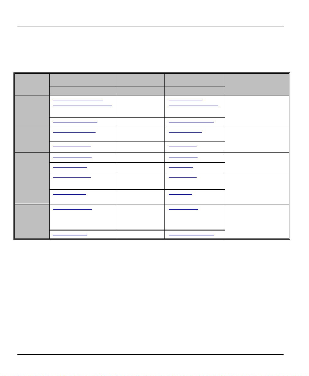
Table of Contents
Customer Support.......................................................................................................iv
Table of Contents .........................................................................................................v
List of Figures.............................................................................................................xi
List of Tables.............................................................................................................xiii
Preface .......................................................................................................................xiv
Chapter 1: Getting to Know Your Bridge/Router................................................1-1
1.1 Quick Feature Overview of the Prestige 1100...................................................................................1-1
1.2 Detailed Features of the Prestige 1100...............................................................................................1-1
1.3 Front Panel LEDs and Back Panel Ports............................................................................................1-3
1.3.1 Front Panel LEDs .........................................................................................................................1-3
1.3.2 Prestige 1100 Back Panel............................................................................................................1-4
1.4 Applications for Prestige 1100.............................................................................................................1-4
1.4.1 Internet Access.............................................................................................................................1-4
Chapter 2: Hardware Installation & Initial Setup...............................................2-1
2.1 Unpacking your Bridge/Router............................................................................................................2-1
2.2 Additional Installation Requirements.................................................................................................2-1
2.3 Connect your WAN Bridge/Router......................................................................................................2-2
2.3.1 Prestige 1100 Connections.........................................................................................................2-2
2.4 Power On Your Prestige 1100 ..............................................................................................................2-3
2.5 Navigating the SMT Interface..............................................................................................................2-5
2.6 Changing the System Password...........................................................................................................2-7
2.7 General Setup..........................................................................................................................................2-9
2.7.1 Note on Bridging........................................................................................................................2-10
2.8 WAN Setup...........................................................................................................................................2-11
2.8.1 Prestige 110 0 WAN Port Setup................................................................................................2-11
2.9 Ethernet Setup.......................................................................................................................................2-12
2.10 General Ethernet Setup..................................................................................................................2-13
2.11 Protocol Dependent Ethernet Setup.............................................................................................2-13
Table of Contents v
Page 6

Prestige 1100 Internet Access Router
Chapter 3: Internet Access......................................................................................3-1
3.1 Route IP Setup.......................................................................................................................................3-1
3.2 TCP/IP Parameters ................................................................................................................................3-2
3.2.1 IP Address and Subnet Mask.....................................................................................................3-2
3.2.2 RIP Setup......................................................................................................................................3-2
3.2.3 DHCP Configuration ...................................................................................................................3-3
3.3 TCP/IP and DHCP Ethernet Setup ..................................................................................................... 3-3
3.4 IP Multicast............................................................................................................................................3-5
3.5 Internet Access Configuration.............................................................................................................3-6
3.6 Single User Account ............................................................................................................................. 3-8
3.6.1 Advantages of SUA.....................................................................................................................3-9
3.6.2 Single User Account Configuration..........................................................................................3-9
3.6.3 Ethernet SUA..............................................................................................................................3-10
3.7 LANs & WANs....................................................................................................................................3-11
3.7.1 LANs, WANs and the Prestige................................................................................................3-11
Chapter 4: Remote Node Configuration for LAN to LAN...................................4-1
4.1 Leased Line Remote Node Profile......................................................................................................4-1
4.2 Outgoing Authentication Protocol ......................................................................................................4-3
4.3 Editing PPP Options.............................................................................................................................4-3
Chapter 5: Remote Node TCP/IP Configuration..................................................5-1
5.1 LAN-to-LAN Application....................................................................................................................5-1
5.2 Remote Node Setup...............................................................................................................................5-2
5.3 Static Route Setup ................................................................................................................................. 5-6
Chapter 6: IPX Configuration.................................................................................6-1
6.1 IPX Network Environment..................................................................................................................6-1
6.1.1 Network and Node Number.......................................................................................................6-1
6.1.2 Frame Types .................................................................................................................................6-1
6.1.3 External Network Number ..........................................................................................................6-2
6.1.4 Internal Network Number...........................................................................................................6-2
6.2 Prestige 1100 in an IPX Environment................................................................................................6-2
6.2.1 Prestige 1100 on LAN with Server ........................................................................................... 6-3
6.2.2 Prestige 1100 on LAN without Server ..................................................................................... 6-3
6.3 IPX Ethernet Setup................................................................................................................................6-4
vi Table of Contents
Page 7

Prestige 1100 Internet Access Router
6.4 LAN-to-LAN Application with Novell IPX......................................................................................6-5
6.4.1 IPX Remote Node Setup.............................................................................................................6-6
6.4.2 IPX Static Route Setup................................................................................................................6-8
Chapter 7: Bridging Setup......................................................................................7-1
7.1 Bridging in General................................................................................................................................7-1
7.2 Bridge Ethernet Setup...........................................................................................................................7-1
7.2.1 Remote Node Bridging Setup.....................................................................................................7-2
7.2.2 Bridge Static Route Setup...........................................................................................................7-4
Chapter 8: Filter Configuration.............................................................................8-1
8.1 About Filtering........................................................................................................................................8-1
8.2 The Filter Structure of the Prestige.....................................................................................................8-1
8.3 Configuring a Filter Set.........................................................................................................................8-3
8.3.1 Filter Rules Summary Menu ......................................................................................................8-4
8.4 Configuring a Filter Rule ......................................................................................................................8-6
8.4.1 Filter Types and SUA...................................................................................................................8-6
8.4.2 TCP/IP Filter Rule........................................................................................................................8-7
8.4.3 Novell IPX Filter Rule...............................................................................................................8-11
8.4.4 Device Filter Rule .......................................................................................................................8-13
8.5 Applying a Filter ...................................................................................................................................8-15
8.5.1 Ethernet traffic.............................................................................................................................8-15
8.5.2 Remote Node Filters ..................................................................................................................8-16
Chapter 9: SNMP Configuration...........................................................................9-1
9.1 About SNMP...........................................................................................................................................9-1
9.2 SNMP Configuration .............................................................................................................................9-1
Chapter 10: System Security.................................................................................10-1
10.1 Changing the System Password....................................................................................................10-1
Chapter 11: Telnet Configuration and Capabilities............................................11-1
11.1 About Telnet Configuration...........................................................................................................11-1
11.2 Telnet Under SUA...........................................................................................................................11-2
11.3 Telnet Capabilities...........................................................................................................................11-2
11.3.1 Single Administrator.............................................................................................................11-2
11.3.2 System Timeout.....................................................................................................................11-2
Table of Contents vii
Page 8

Prestige 1100 Internet Access Router
Chapter 12: System Maintenance.........................................................................12-1
12.1 System Status..................................................................................................................................12-2
12.2 System Information........................................................................................................................12-4
12.2.1 Console Port Speed...............................................................................................................12-5
12.3 Log and Trace..................................................................................................................................12-5
12.3.1 Viewing Error Log ................................................................................................................12-5
12.3.2 Syslog And Accounting.......................................................................................................12-6
12.4 Diagnostic........................................................................................................................................12-7
12.5 Filename conventions....................................................................................................................12-8
12.6 Back up Configuration...................................................................................................................12-9
12.6.1 Backup using the Console Port...........................................................................................12-9
12.6.2 Back up using FTP..............................................................................................................12-10
12.6.3 Back up using TFTP...........................................................................................................12-10
12.7 Restore Configuration..................................................................................................................12-11
12.7.1 Restore using the Console Port.........................................................................................12-11
12.7.2 Restore using FTP...............................................................................................................12-11
12.7.3 Restore using TFTP............................................................................................................12-12
12.8 Upload Firmware..........................................................................................................................12-12
12.8.1 Dual Firmware Block Structure ........................................................................................12-13
12.8.2 Upload Router Firmware via the Console Port..............................................................12-13
12.8.3 Upload Router Firmwa re using FTP................................................................................12-14
12.8.4 Upload Router Firmware using TFTP.............................................................................12-15
12.9 Upload Router Configuration File .............................................................................................12-15
12.9.1 Upload Router Configuration File using the Console Port..........................................12-15
12.9.2 Upload Router Configuration File using FTP................................................................12-16
12.9.3 Upload Router Configuration File using TFTP.............................................................12-17
12.9.4 Boot Module Commands...................................................................................................12-18
12.10 Command Interpreter Mode.......................................................................................................12-19
Chapter 13: IP Policy Routing ...............................................................................13-1
13.1 Introduction ..................................................................................................................................... 13-1
13.1.1 Benefits...................................................................................................................................13-1
13.1.2 Routing Policy.......................................................................................................................13-1
13.1.3 IP Policy Routing Setup......................................................................................................13-2
13.2 Applying an IP Policy....................................................................................................................13-6
13.2.1 Ethernet IP Policies ..............................................................................................................13-6
13.2.2 Remote Node IP Routing Policies .....................................................................................13-6
viii Table of Contents
Page 9

Prestige 1100 Internet Access Router
Chapter 14: Troubleshooting................................................................................14-1
14.1 Problems Starting Up the Prestige 1100......................................................................................14-1
14.2 Problems With the WAN Port .......................................................................................................14-2
14.3 Problems with the LAN Interface.................................................................................................14-2
14.4 Problems Connecting to a Remote Node or ISP........................................................................14-2
Acronyms and Abbreviations ....................................................................................A
Index.............................................................................................................................C
Table of Contents ix
Page 10

Page 11

Prestige 1100 Internet Access Router
List of Figures
Figure 1-1 Remote Configuration.....................................................................................................................1-2
Figure 1-2 Prestige 1100 Front Panel..............................................................................................................1-3
Figure 1-3 Back Panel........................................................................................................................................1-4
Figure 1-4 Internet Access Application ...........................................................................................................1-5
Figure 1-5 LAN-to-LAN Application................................................................................................................1-6
Figure 2-1 P1100 Connections..........................................................................................................................2-2
Figure 2-2 Power-On Display...........................................................................................................................2-3
Figure 2-3 Login Screen.....................................................................................................................................2-4
Figure 2-4 SMT Main Menu..............................................................................................................................2-6
Figure 2-5 Menu 23 - System Security.............................................................................................................2-7
Figure 2-6 Menu 23.1 - System Security - Change Password......................................................................2-8
Figure 2-7 Menu 1 - General Setup..................................................................................................................2-9
Figure 2-8 Menu 2 - WAN Port Setup............................................................................................................2-11
Figure 2-9 Menu 3 - Ethernet Setup - Select LAN........................................................................................2-12
Figure 2-10 Menu 3 – Ethernet Setup............................................................................................................2-12
Figure 2-11 Menu 3.1 - General Ethernet Setup..........................................................................................2-13
Figure 3-1 Menu 1 - General Setup..................................................................................................................3-1
Figure 3-2 Menu 3.2 - TCP/IP and DHCP Ethernet Setup..........................................................................3-4
Figure 3-3 Menu 4 - Internet Access Setup.....................................................................................................3-6
Figure 3-4 Single User Account Topology......................................................................................................3-8
Figure 3-5 Menu 4 - Internet Access Setup for Single User Account ......................................................... 3-9
Figure 3-6 Ethernet SUA Example.................................................................................................................3-10
Figure 3-7 LAN & WAN IPs.............................................................................................................................3-11
Figure 3-8 Ethernet as WAN port....................................................................................................................3-11
Figure 4-1 Menu 11.1 - Remote Node Profile for Leased Lines...................................................................4-1
Figure 4-2 Menu 11.2 - Remote Node PPP Options......................................................................................4-4
Figure 5-1 LAN-to-LAN Application with TCP/IP.........................................................................................5-1
Figure 5-2 Menu 11.3- Remote Node TCP/IP Options ..................................................................................5-2
Figure 5-3 Sample IP Addresses for a TCP/IP LAN-to-LAN Connection .................................................5-3
Figure 5-4 Example of Static Routing Topology............................................................................................5-6
Figure 5-5 Menu 12 - Static Route Setup........................................................................................................5-7
Figure 5-6 Menu 12.1 - IP Static Route Setup................................................................................................5-7
Figure 5-7 Edit IP Static Route.........................................................................................................................5-7
Figure 6-1 NetWare Network Numbers............................................................................................................6-2
Figure 6-2 Prestige in an IPX Environment....................................................................................................6-3
Figure 6-3 Menu 3.3 - Novell IPX Ethernet Setup.........................................................................................6-4
Figure 6-4 LAN-to-LAN Application with Novell IPX...................................................................................6-5
Figure 6-5 Menu 11.3 - Remote Node Novell IPX Options..........................................................................6-6
Figure 6-6 Menu 12.2.1 - Edit IPX Static Route ............................................................................................6-8
Figure 7-1 Menu 3.5 - Bridge Ethernet Setup................................................................................................7-2
List of Figures xi
Page 12

Prestige 1100 Internet Access Router
Figure 7-2 Menu 11.3 - Remote Node Bridging Options ...............................................................................7-3
Figure 7-3 Menu 12.3.1 - Edit Bridge Static Route........................................................................................7-4
Figure 8-1 Filter Rule Process...........................................................................................................................8-2
Figure 8-2 Menu 21 - Filter Set Configuration...............................................................................................8-3
Figure 8-3 Menu 21.1 - Filter Rules Summary................................................................................................8-4
Figure 8-4 Protocol and Device Filter Sets.....................................................................................................8-7
Figure 8-5 Menu 21.1.1 - TCP/IP Filter Rule.................................................................................................8-8
Figure 8-6 Executing an IP Filter..................................................................................................................8-10
Figure 8-7 Menu 21.1.1 - IPX Filter Rule......................................................................................................8-11
Figure 8-8 Menu 21.1.2 - Device Filter Rule...............................................................................................8-14
Figure 8-9 Filtering Ethernet Traffic.............................................................................................................8-15
Figure 8-10 Filtering Remote Node traffic...................................................................................................8-16
Figure 9-1 Menu 22 - SNMP Configuration....................................................................................................9-1
Figure 10-1 Menu 23 - System Security........................................................................................................10-1
Figure 10-2 Menu 23.1 - System Security - Change Password.................................................................10-2
Figure 11-1 Telnet Configuration on a TCP/IP Network ............................................................................11-1
Figure 12-1 Menu 24 - System Maintenance................................................................................................12-1
Figure 12-2 Menu 24.1 - System Maintenance – Status.............................................................................12-2
Figure 12-3 System Maintenance – Information.........................................................................................12-4
Figure 12-4 Menu 24.2.2 – System Maintenance – Change Console Port Speed................................12-5
Figure 12-5 Examples of Error and Information Messages.......................................................................12-6
Figure 12-6 Menu 24.3.2 - System Maintenance - Syslog and Accounting.............................................12-6
Figure 12-7 Menu 24.4 - System Maintenance - Diagnostic.....................................................................12-7
Figure 12-8 Menu 24.5 –Backup Configuration using the Console Port.............................................12-10
Figure 12-9 Backup Configuration using FTP...........................................................................................12-10
Figure 12-10 Menu 24.6 –Restore Configuration using the Console Port..........................................12-11
Figure 12-11 Restore Configuration using FTP.........................................................................................12-12
Figure 12-12 Menu 24.7 -- System Maintenance - Upload Firmware ...................................................12-13
Figure 12-13 Menu 24.7.1 –Upload ZyNOS Code using the Console Port..........................................12-14
Figure 12-14 Menu 24.7.1. – Upload Router Firmware using FTP.......................................................12-14
Figure 12-15 Menu 24.7.2 –Upload Router Configuration File.............................................................12-16
Figure 12-16 Menu 24.7.2 – Upload Router Configuration File using FTP........................................12-16
Figure 12-17 Boot module commands.........................................................................................................12-18
Figure 12-18 Command mode.......................................................................................................................12-19
Figure 13-1 IP Routing Policy Setup.............................................................................................................13-2
Figure 13-2 Menu 25 - IP Routing Policy Summary...................................................................................13-3
Figure 13-3 IP Routing Policy........................................................................................................................13-4
Figure 13-4 Menu 3.1.1 - General Ethernet Setup......................................................................................13-6
Figure 13-5 Menu 11.3 - Remote Node Network Layer Options ...............................................................13-7
xii List of Figures
Page 13

Prestige 1100 Internet Access Router
List of Tables
Table 1-1 LED Functions ................................................................................................................................... 1-3
Table 2-1 Main Menu Commands.....................................................................................................................2-5
Table 2-2 Main Menu Summary........................................................................................................................2-6
Table 2-3 General Setup Menu Fields ............................................................................................................2-10
Table 2-4 WAN Setup Menu Fields.................................................................................................................2-11
Table 3-1 DHCP Ethernet Setup Menu Fields ................................................................................................3-4
Table 3-2 TCP/IP Ethernet Setup Menu Fields..............................................................................................3-5
Table 3-3 Internet Account Information...........................................................................................................3-6
Table 3-4 Internet Access Setup Menu Fields.................................................................................................3-7
Table 3-5 Single User Account Menu Fields .................................................................................................3-10
Table 4-1 Remote Node Profile Menu Fields for Leased Lines....................................................................4-2
Table 4-2 Remote Node PPP Options Menu Fields.......................................................................................4-4
Table 5-1 TCP/IP related fields in Remote Node Profile..............................................................................5-3
Table 5-2 Remote Node TCP/IP Configuration..............................................................................................5-4
Table 5-3 Edit IP Static Route Menu Fields ....................................................................................................5-8
Table 6-1 Novell IPX Ethernet Setup Fields...................................................................................................6-4
Table 6-2 Remote Node Novell IPX Options...................................................................................................6-7
Table 6-3 Edit IPX Static Route Menu Fields.................................................................................................6-9
Table 7-1 Remote Node Bridge Options..........................................................................................................7-3
Table 7-2 Bridge Static Route Menu Fields....................................................................................................7-4
Table 8-1 Abbreviations Used in the Filter Rules Summary Menu.............................................................8-4
Table 8-2 Abbreviations Used If Filter Type Is IP..........................................................................................8-5
Table 8-3 Abbreviations Used If Filter Type Is IPX.......................................................................................8-6
Table 8-4 Abbreviations Used If Filter Type Is Dev ....................................................................................... 8-6
Table 8-5 TCP/IP Filter Rule Menu Fields.....................................................................................................8-8
Table 8-6 IPX Filter Rule Menu Fields ..........................................................................................................8-12
Table 8-7 Device Filter Rule Menu Fields....................................................................................................8-14
Table 9-1 SNMP Configuration Menu Fields.................................................................................................9-2
Table 12-1 System Maintenance - Status Menu Fields ................................................................................12-3
Table 12-2 Fields in System Maintenance.....................................................................................................12-4
Table 12-3 System Maintenance Menu Syslog Parameters........................................................................12-7
Table 12-4 System Maintenance Menu Diagnostic......................................................................................12-8
Table 12-5 Filename Conventions..................................................................................................................12-9
Table 13-1 IP Routing Policy Summary.........................................................................................................13-4
Table 13-2 IP Routing Policy...........................................................................................................................13-5
Table 14-1 Troubleshooting the Start-Up of your Prestige 1100...............................................................14-1
Table 14-2 Troubleshooting a WAN Port Connection .................................................................................14-2
Table 14-3 Troubleshooting the LAN Interface.............................................................................................14-2
Table 14-4 Troubleshooting a Connection to a Remote Node or ISP.......................................................14-2
List of Tables xiii
Page 14

Prestige 1100 Internet Access Router
Preface
About Your Bridge/Router
The Prestige 1100 is a high-performance bridge/router that offers a complete solution for your WAN
applications such as Internet access and multi-protocol LAN-to-LAN connections for SMB (Small &
Medium Size Businesses). It integrates the routing and bridging functions in a single package and is
easy to install and to configure since you do not need to set any switches.
In addition, the Prestige 1100 supports synchronous mode on its WAN port, allowing it to connect to
T1/E1 or FT1/FE1 (Fractional T1/E1) leased lines via CSU/DSUs (Channel Service Unit/Data Service
Units).
About This User's Guide
This user's guide covers all operations of the Prestige 1100 and shows you how to get the best out of
the multiple advanced features of your Prestige router. It is designed to help you configure the Prestige
correctly for various applications.
Related Documentation
Ø Supporting Disk
More detailed information about the Prestige and examples of its use can be found in our Supporting
Disk. This disk contains a Prestige Bulletin (a release note highlighting new features), a FAQ, a
Configuration Guide, Support Tools for extra configuration, CI Commands Reference, Cable Pin
assignments and Reference Documentation (Training Material and Support Accessories).
Ø Packing List Card
You should have a Packing List Card that lists all items that should have come with your Prestige.
Syntax Conventions
• “Enter” means for you to type one or more characters and press the carriage return. “Select” or
“Choose” means for you to select one from the predefined choices.
• The SMT menu titles and labels are in Bold Times font. The choices of a menu item are enclosed
in square brackets [xxx]. A single keystroke is in Arial font and enclosed in square brackets, for
instance, [ENTER] means the Enter, or carriage return, key; [ESC] means the Escape key.
• For brevity’s sake, we will use “e.g.” as a shorthand for “for instance”, and “i.e.” as a shorthand
for “that is” or “in other words” throughout this manual.
xiv Preface
Page 15

Prestige 1100 Internet Access Router
Chapter 1:
Getting to Know Your Bridge/Router
The Prestige 1100 is a high-performance bridge/router that offers a complete solution for your WAN
applications such as Internet access and multi-protocol LAN-to-LAN connections for SMB (Small &
Medium Size Businesses). It integrates the routing and bridging functions in a single package and is
easy to install and to configure since you do not need to set any switches.
In addition, the Prestige 1100 supports synchronous mode on its WAN port, allowing it to connect to
T1/E1 or FT1/FE1 (Fractional T1/E1) leased lines via CSU/DSUs (Channel Service Unit/Data Service
Units).
1.1 Quick Feature Overview of the Prestige 1100
§ One WAN port with various interface support: RS-449/V.35/X.21/EIA 530/RS-232
§ Two auto-sensing 10/100M Ethernet interfaces
§ PPP for WAN connection
§ IP/IPX and transparent bridging
§ IP Multicast
§ IP Policy Routing to support traffic management
§ Network Address Translation for private IP address support
§ Remote Management
§ SNMP manageable
§ IP packet filtering, including network level and device level filtering
§ 100V~240V internal power supply and rack size for MIS environment
1.2 Detailed Features of the Prestige 1100
The following are the key features of the P1100.
One WAN port for various WAN Solutions
Your Prestige 1100 provides one WAN port with a 68-pin D type connector. It supports several
interfaces (RS-449/V.35/X.21/EIA 530/RS-232) to connect to various WAN devices for up to E1 speed
(2.048Mbps).
Getting to know your Prestige 1-1
Page 16
Prestige 1100 Internet Access Router
Two 10/100 Ethernet LANs
One 10/100M Ethernet interface is designed for high performance LAN environment. The other
10/100M Ethernet interface can be reserved for connecting to a Web/FTP server for public Internet
access.
Most Complete NAT Support
ZyXEL NAT technology supports not only private IP for Internet access sharing and security
protection, but also popular Internet multimedia applications such as Microsoft NetMeeting and
CuSeeMe.
Multiple Protocol Support
§ TCP/IP (Transmission Control Protocol/Internet Protocol) network layer protocol.
§ Novell IPX (Internetwork Packet eXchange) protocol.
§ Transparently bridging for network layer protocols that the Prestige 1100 does not route.
§ PPP (Point-to-Point Protocol) link layer protocol.
§ SUA™ (Single User Account) for NAT (Network Address Translation).
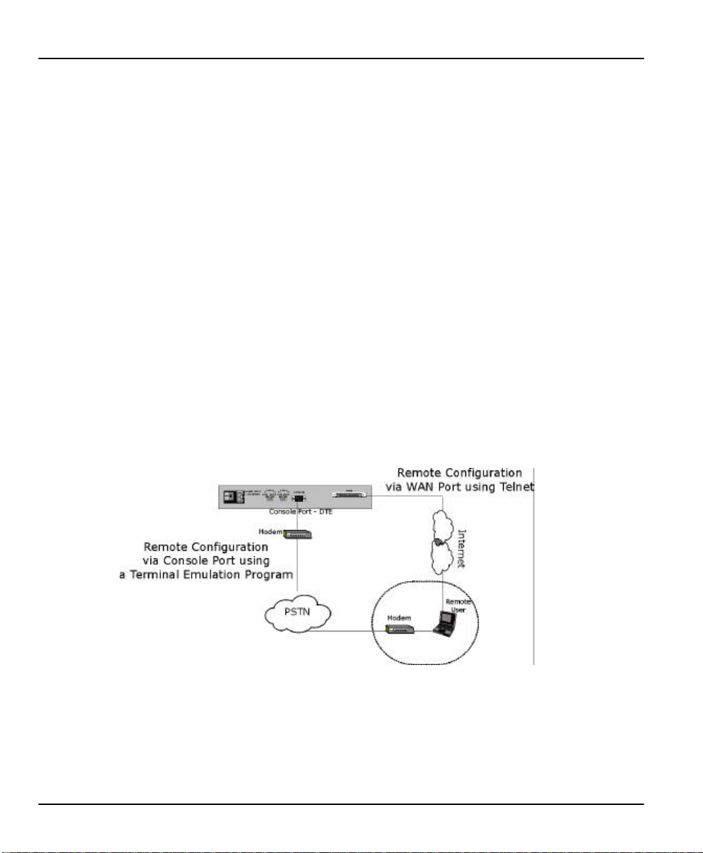
Remote Configuration
The P1100 may be remotely configured via the console port as well as the WAN port. A modem can be
attached directly to the console port (DTE) for easy, alternative, remote configuration. See Page 2-2
for more information on P1100 connections.
Figure 1-1 Remote Configuration
Full Network Management
Your Prestige 1100 supports SNMP (Simple Network Management Protocol) in addition to menudriven network management via the console port or a telnet connection. With remote management,
built-in diagnostic tools and syslog support, users can manage the P1100 with no extra effort.
1-2 Getting to know your Prestige
Page 17
Prestige 1100 Internet Access Router
DHCP Support
DHCP (Dynamic Host Configuration Protocol) allows you to dynamically and automatically assign IP
address to hosts on your network.
Data Compression
Your Prestige incorporates Stac data compression to speed up data transfer. Stac is the de facto
standard of data compression over PPP links.
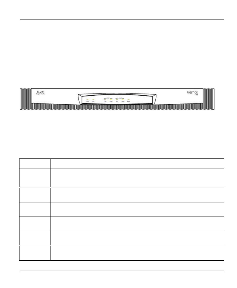
1.3 Front Panel LEDs and Back Panel Ports
Figure 1-2 Prestige 1100 Front Panel
1.3.1 Front Panel LEDs
The LED lights on the front panel indicate the operational status of your Prestige. Table 1-1 (next)
describes the LED functions:
Table 1-1 LED Functions
PWR The PWR (power) LED is on when power is applied to the Prestige.
SYS A steady on SYS (system) LED indicates the Prestige is on and functioning properly while an off SYS
LAN-1_10M A steady green light indicates a 10Mbps Ethernet connection. The LED blinks when data is being sent
LAN-1_100M A steady orange light indicates a 100Mbps Ethernet Connection. The LED blinks when data is being
LAN-2_10M A steady green light indicates a 10Mbps Ethernet connection. The LED blinks when data is being sent
LAN-2_100M A steady orange light indicates a 100Mbps Ethernet Connection. The LED blinks when data is being
WAN The WAN LED is on when the Prestige is connected successfully to a WAN device. The LED blinks
LED indicates the system is not ready or a malfunction. The system is rebooting when the SYS LED is
blinking.
or received.
sent or received.
or received.
sent or received.
when data is sent or received. The LED is off when the link is down.
Getting to know your Prestige 1-3
Page 18
Prestige 1100 Internet Access Router
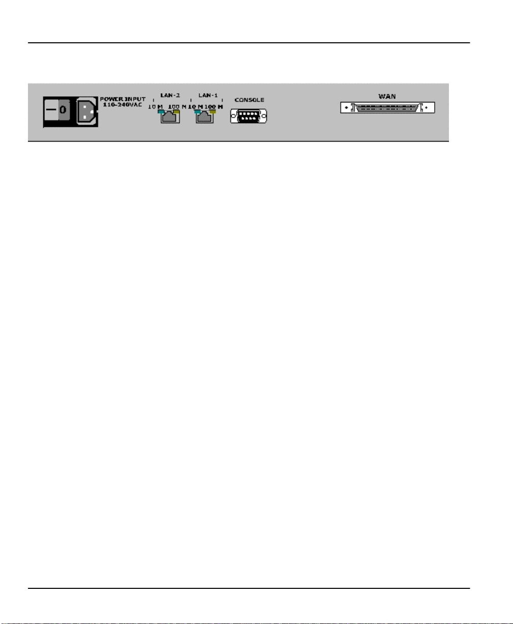
1.3.2 Prestige 1100 Back Panel
Figure 1-3 Back Panel
The diagram above shows the rear panel of your Prestige 1100. Refer to this diagram when making
connections.
•: POWER INPUT = Power cord receptacle and switch
‚: LAN1 = RJ-45 10/100 Mbps Ethernet port
ƒ: LAN2 = RJ-45 10/100 Mbps Ethernet port
„: CONSOLE = DB-9 Console port
…: WAN = 68-pin D-type connector
1.4 Applications for Prestige 1100
The following sections show you the possible applications that you can use your Prestige for.
1.4.1 Internet Access
The Prestige 1100 is the ideal high-speed Internet access solution. Your Prestige 1100 supports the
TCP/IP protocol that the Internet uses exclusively. A typical Internet access application is shown
below:
1-4 Getting to know your Prestige
Page 19
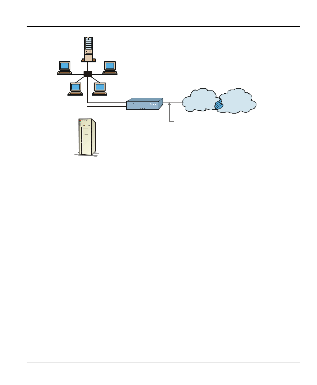
Corporate LAN
Server
Prestige 1100 Internet Access Router
Prestige
1100
Leased Line
WEB/FTP
Figure 1-4 Internet Access Application
Internet Single User Account
For a business environment, your Prestige offers the Single User Account (SUA) feature that allows
multiple users on the LAN (Local Area Network) to access the Internet concurrently for the cost of a
single user. The SUA address mapping can also be used for other LAN to LAN connections.
INTERNET
Getting to know your Prestige 1-5
Page 20
Prestige 1100 Internet Access Router
Server
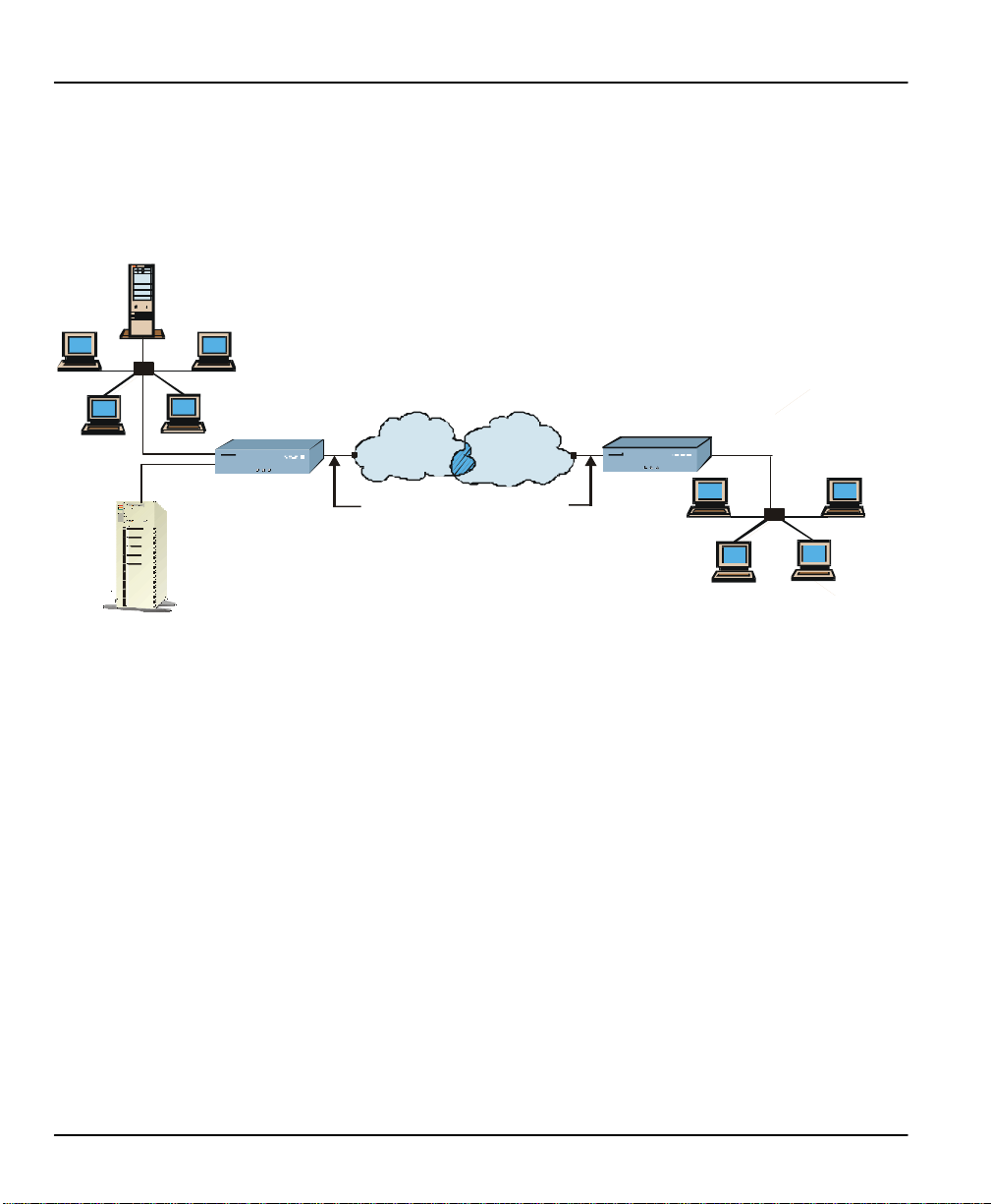
Multi-protocol/Multilink LAN-to-LAN Connection
You can use the Prestige to connect two geographically dispersed networks over the WAN connection.
The Prestige supports TCP/IP and Novell IPX routing, as well as transparent bridging for other
network layer protocols. A typical LAN-to-LAN application for your Prestige is shown below:
Corporate LAN
WEB/FTP
Prestige
1100
Figure 1-5 LAN-to-LAN Application
INTERNET
Leased Lines (T1/E1)
Prestige
1100
Branch Office
LAN
1-6 Getting to know your Prestige
Page 21

Prestige 1100 Internet Access Router
Chapter 2:
Hardware Installation & Initial Setup
2.1 Unpacking your Bridge/Router
This chapter explains how to connect to the hardware and to perform the initial setup. Before installing
be sure that all components listed with the enclosed packing slip are included.
2.2 Additional Installation Requirements
In addition to the contents of your package, there are other hardware and software requirements you
need before you can install and use your Prestige. These requirements include:
l A computer with Ethernet 10Base-T or 100Base-TX NIC (Network Interface Card ).
l A computer equipped with communications software configured to the following parameters:
Ø VT100 terminal emulation.
Ø 9600 Baud.
Ø No parity, 8 Data bits, 1 Stop bit.
Ø Flow Control set to None.
After the Prestige is properly set up, you can make future changes to the configuration through telnet
connections.
Hardware Installation & Initial Setup 2-1
Page 22
Prestige 1100 Internet Access Router
2.3 Connect your WAN Bridge/Router
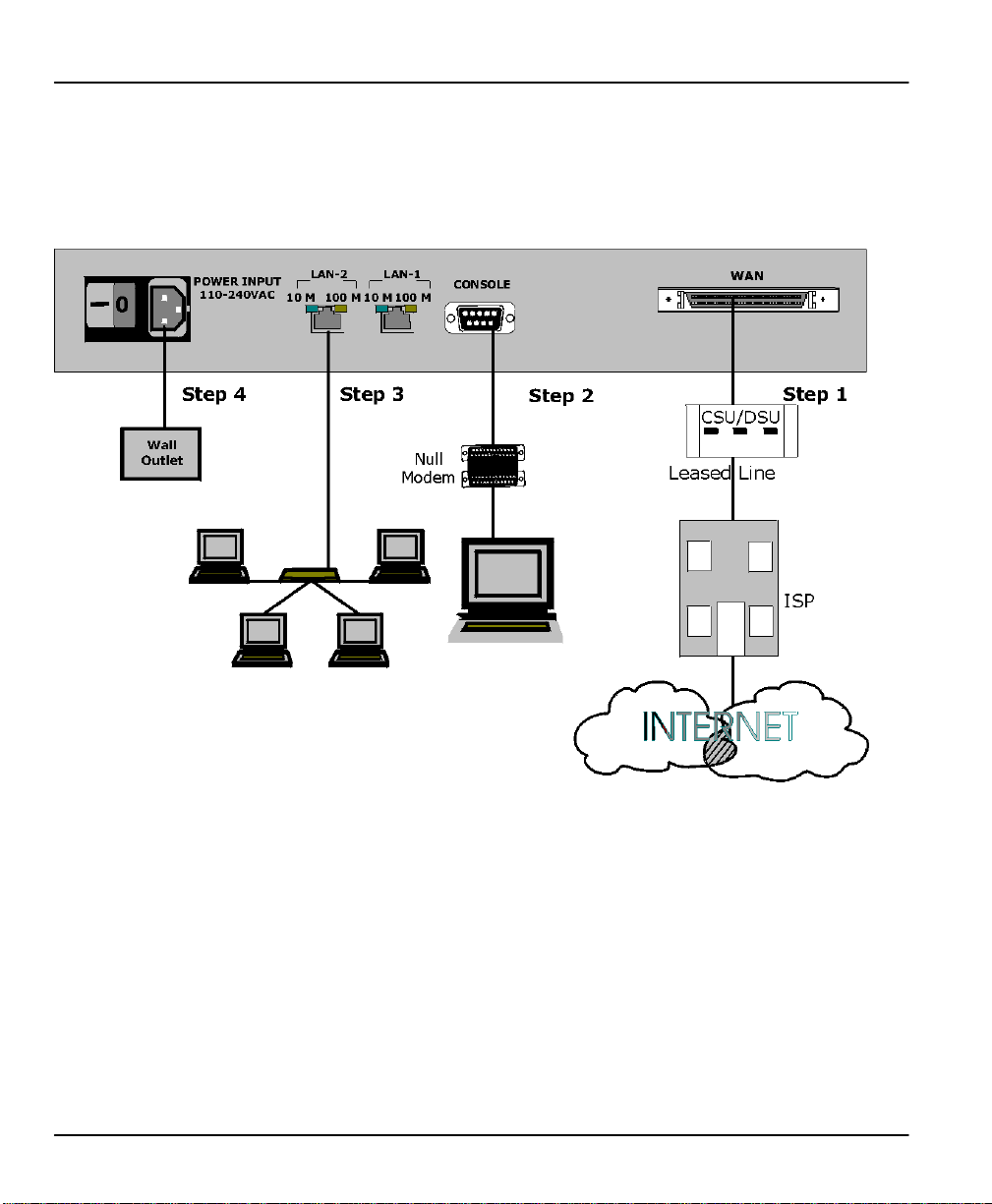
2.3.1 Prestige 1100 Connections
This section outlines how to make the connections to your Prestige 1100. Please refer to the following
figure when making connections to the P1100.
Figure 2-1 P1100 Connections
Step 1. Connect WAN Devices to your Prestige 1100
Connect the port of a WAN device to the WAN port on the Prestige 1100 using an appropriate cable.
Please consult the documentation of your WAN device for detailed information when making the
connections.
Step 2. Connecting the Console Port
For the initial configuration of your Prestige, you need to use terminal emulator software on a
workstation and connect it to the Prestige through the console port. A modem can be connected
directly to the Prestige console port for remote configuration (see Figure 1-1). The PC - Prestige
console port direct connection must be made via a null modem (supplied). The Prestige console port is
2-2 Hardware Installation & Initial Setup
Page 23

Prestige 1100 Internet Access Router
Copyright (c) 1999 ZyXEL Communications Corp.
a DTE (Data Terminal Equipment) device, not a DCE (Data Circuit-terminating Equipment) device, so
the null modem is needed to allow connection to the workstation console port, which is of course a
DTE device also. Connect the 9-pin (smaller) end of the console cable to the console port of the
Prestige and the 25-pin (bigger) end to the null modem. Then connect the null modem to a serial port
(COM1, COM2 or other COM port) of your workstation. You can use an extension RS-232 cable if
the enclosed one is too short. After the initial setup, you can modify the configuration remotely
through telnet connections or via a modem connection. See the Telnet Configuration and
Capabilities chapter for more information on using telnet to configure your Prestige.
Step 3. Connect your Prestige 1100 to Ethernet
Connect one end of a STP (Shielded Twisted Pair) cable to the Ethernet port of the Prestige 1100 and
the other to a hub using a straight-through cable with RJ-45 connectors. If you connect the Prestige
1100 to a workstation directly without a hub, you must use a crossover cable.
Step 4. Connect the Power Cord to your Prestige 1100
Connect the power cord to the port labeled POWER INPUT on the rear panel of your Prestige 1100.
2.4 Power On Your Prestige 1100
At this point, you should have connected the console cable, the WAN device, the Ethernet cable(s), and
the power cord. You can now power on your Prestige 1100 by flipping the power switch to on. (Note:
“I” =ON, “O” = OFF)
Initial Screen
When you power on your Prestige 1100, the router performs several internal tests and initializes the
WAN devices. After the initialization, the Prestige asks you to press [ENTER] to continue, as shown
below:
ethernet address: 00:a0:c5:00:50:01
ethernet address: 00:a0:c5:00:50:02
Press ENTER to continue...
Step 1. Enter Password
After you press [ENTER], the Login screen appears prompting you to enter the password, as shown in
the next figure.
Hardware Installation & Initial Setup 2-3
Figure 2-2 Power-On Display
Page 24

Prestige 1100 Internet Access Router
For your first login, enter the default password [1234]. As you enter the password, the screen
displays an (X) for each character you type.
Enter Password : XXXX
Figure 2-3 Login Screen
Please note that if there is no activity for longer than 5 minutes after you log in, your Prestige will
automatically log you out and will display a blank screen. If you see a blank screen, press [ENTER] to
bring up the password screen again.
2-4 Hardware Installation & Initial Setup
Page 25

Prestige 1100 Internet Access Router
2.5 Navigating the SMT Interface
The SMT (System Management Terminal) is the interface that you use to configure your Prestige.
Several operations that you should be familiar with before you attempt to modify the configuration are
listed in Table 2-1.
Table 2-1 Main Menu Commands
Operation Press/<read> Description
Move forward to
another menu
Move backward to
a previous menu
Move to a “hidden”
menu
Move the cursor [ENTER] or
Enter information Fill in, or
Required fields
N/A fields <N/A> Some of the fields in the SMT will show a <N/A>. This symbol refers
Save your
configuration
Exit the SMT Type 99, then
[ENTER] To move forward to a sub-menu, type in the number of the desired
sub-menu and press [ENTER].
[ESC] Press the [ENTER] key to move back to the previous menu.
Press the
[Space bar] to
change [No] to
[Yes] then
press
[ENTER].
[Up]/[Down]
arrow keys
Press the
[Space bar] to
toggle
<?>
[ENTER] Save your configuration by pressing [ENTER] at the message:
press
[ENTER].
Fields beginning with “Edit” lead to hidden menus and have a default
setting of [No]. Press the [Space bar] to change [No] to [Yes], then
press [ENTER] to go to a “hidden” menu.
Within a menu, press [ENTER] to move to the next field. You can
also use the [Up]/[Down] arrow keys to move to the previous and the
next field, respectively.
There are two types of fields that you will need to fill in. The first
requires you to type in the appropriate information. The second gives
you choices to choose from. In the second case, press the [Space
bar] to cycle through the available choices.
All fields with the symbol <?> must be filled in order be able to save
the new configuration.
to an option that is not available.
[Press ENTER to confirm or ESC to cancel]. Saving the data on the
screen will take you, in most cases to the previous menu.
Type 99 at the Main Menu prompt and press [ENTER] to exit the
SMT interface.
Hardware Installation & Initial Setup 2-5
Page 26

Prestige 1100 Internet Access Router
Copyright (c) 1999 ZyXEL Communications Corp.
The SMT displays the Main Menu, as shown below:
P1100 Main Menu
Getting Started
1. General Setup
2. WAN Setup
3. Ethernet Setup
4. Internet Access Setup
Advanced Applications
11. Remote Node Setup
12. Static Routing Setup
Advanced Management
21. Filter Set Configuration
22. SNMP Configuration
23. System Security
24. System Maintenance
25. IP Routing Policy Setup
15. SUA Server Setup
Enter Menu Selection Number:
99. Exit
Figure 2-4 SMT Main Menu
The following table shows the Main Menu Summary,
Table 2-2 Main Menu Summary
# Menu Title Description
1 General Setup Use this menu to setup general information and enable routing or bridging
2 WAN Setup Use this menu to setup the WAN port configuration.
3 Ethernet Setup Use this menu to setup the Ethernet configuration.
4 Internet Access Setup A quick and easy way to setup Internet connection.
11 Remote Node Setup Use this menu to setup the remote node for LAN-to-LAN connection,
12 Static Routing Setup Use this menu to setup static route for different protocols. There are eight
15 SUA Server Setup Use this menu to specify inside servers when SUA is selected.
21 Filter Set Configuration Setup filters to be used in Menu 3 and Menu 11 to provide security, call
22 SNMP Configuration Use this menu to setup SNMP related parameters
23 System Security Use this menu to setup security related parameters.
24 System Maintenance Provides system status, diagnostics, firmware upload, etc.
25 IP Routing Policy Setup Setup configuration for Routing Policies.
99 Exit To exit from SMT and return to the blank screen.
of specific protocols.
including Internet connection.
static routes for each protocol.
control, etc.
2-6 Hardware Installation & Initial Setup
Page 27

Prestige 1100 Internet Access Router
Menu 23 - System Security
2.6 Changing the System Password
The first thing you should do before anything else is to change the default system password by
following the steps below:
Step 1. Select option 23. System Security in the Main Menu. This will open Menu 23 - System
Security as below:
1. Change Password
Enter Menu Selection Number
Figure 2-5 Menu 23 - System Security
Step 2. From the System Security Menu, select option 1. Change Password to bring up Menu 23.1
- System Security - Change Password.
Hardware Installation & Initial Setup 2-7
Page 28

Prestige 1100 Internet Access Router
Menu 23.1 - System Security - Change Password
Step 3. When submenu 23.1- System Security-Change Password appears, as shown below, enter
the existing system password, i.e., [1234], then press [ENTER].
Old Password= XXXX
New Password= XXXX
Retype to confirm= XXXX
Press ENTER to Confirm or ESC to Cancel:
Figure 2-6 Menu 23.1 - System Security - Change Password
Step 4. Enter your new system password and press [ENTER].
Step 5. Re-type your new system password for confirmation and press [ENTER].
2-8 Hardware Installation & Initial Setup
Page 29

Prestige 1100 Internet Access Router
Menu 1 - General Setup
2.7 General Setup
The Menu 1 - General Setup contains administrative and system-related information.
Step 1. Select option 1. General Setup in the Main Menu by typing 1 at the menu selection
number prompt.
Step 2. The Menu 1 - General Setup screen appears, as shown. Fill in the required fields marked [?]
and turn on the individual protocols for your particular application, as explained in the
following table.
System Name= p1100
Location= location
Contact Person's Name= name
Route IP= Yes
Route IPX= No
Bridge= No
Press ENTER to Confirm or ESC to Cancel:
Figure 2-7 Menu 1 - General Setup
Hardware Installation & Initial Setup 2-9
Page 30

Prestige 1100 Internet Access Router
Table 2-3 General Setup Menu Fields
Field Description Example
System Name Choose a descriptive name for identification purposes.
This name can be up to 8 alphanumeric characters long.
Spaces are not allowed, but dashes “-” and underscores
"_" are accepted. This name can be retrieved remotely
via SNMP and will be displayed at the prompt in the
Command Mode.
Location (optional) Enter the geographic location (up to 31 characters) of
your Prestige 1100.
Contact Person's
Name (optional)
Protocols: Turn on or off the individual protocols for your particular
Route IP
Route IPX
Bridge
Enter the name (up to 8 characters) of the person in
charge of this Prestige 1100.
application.
Selecting [Yes] to enable IP routing. You must enable IP
routing for Internet access.
Selecting [Yes] to enable IPX routing.
Selecting [Yes] to enable bridging. Packets that the
Prestige 1100 does not route are transparently bridged.
2.7.1 Note on Bridging
P1100
location
name
Press space-
bar to toggle
[Yes/No]
[Yes/No]
[Yes/No]
When bridging is enabled, your Prestige forwards any packet that it does not route. Without bridging,
the packets that the Prestige does not route are simply discarded. Compared to routing, bridging
generates far more traffic for the same network layer protocol, and uses more CPU cycles and memory.
2-10 Hardware Installation & Initial Setup
Page 31

Prestige 1100 Internet Access Router
Menu 2 - WAN Port Setup
2.8 WAN Setup
This section describes how to configure the WAN port and a WAN device using Menu 2- WAN Setup.
When you finish the setup, the Prestige uses this information to initialize the WAN port and the
attached WAN device.
2.8.1 Prestige 1100 WAN Port Setup
Select option 2. WAN Setup in the Main Menu by typing 2 at the menu selection number prompt.
Clock Source = External
Port Speed = N/A
Press Enter to Confirm or ESC to Cancel:
Press Spacebar to Toggle
Figure 2-8 Menu 2 - WAN Port Setup
Table 2-4 WAN Setup Menu Fields
Field Description Example
Clock Source An external device controls timing. The P1100
currently only supports an external clock source.
Port Speed Set by External Device N/A
External
Hardware Installation & Initial Setup 2-11
Page 32

Prestige 1100 Internet Access Router
Menu 3 - Ethernet Setup (LAN 1)
Menu 3 – Ethernet Setup
2.9 Ethernet Setup
This section describes how to configure the Ethernet using Menu 3 – Ethernet Setup. There are
actually three Menu 3s:
1st. Menu 3 – Ethernet Setup – allows you to select the LAN (1 or 2) you wish to configure.
2nd. Menu 3 - Ethernet Setup (LAN 1) – allows you to configure the LAN 1 Ethernet interfaces.
Choose 1 from the first Menu 3 to get to this menu.
3rd. Menu 3 - Ethernet Setup (LAN 2) – allows you to configure the LAN 2 Ethernet interfaces.
Choose 2 from the first Menu 3 to get to this menu.
From the Main Menu, enter 3 to bring up (the first) Menu 3 – Ethernet Setup. Select the LAN that
you wish to configure.
1. LAN1
2. LAN2
Figure 2-9 Menu 3 - Ethernet Setup - Select LAN
Select 1 to bring you to Menu 3 - Ethernet Setup (LAN 1) that you will use to configure the Ethernet
interfaces. These submenus are also identical for Menu 3 - Ethernet Setup (LAN 2).
1. General Setup
2. TCP/IP and DHCP Setup
3. Novell IPX Setup
4. Bridge Setup
Enter Menu Selection Number:
Figure 2-10 Menu 3 – Ethernet Setup
2-12 Hardware Installation & Initial Setup
Page 33

Prestige 1100 Internet Access Router
Menu 3.1 - General Ethernet Setup
2.10 General Ethernet Setup
This menu allows you to specify the filter sets that you wish to apply to the Ethernet traffic. You
seldom need to filter Ethernet traffic, however, the filter sets may be useful to block certain packets,
reducing traffic and preventing security breaches.
From Menu 3 - Ethernet Setup, enter 1 to go to Menu 3.1 -General Ethernet Setup.
Input Filter Sets:
protocol filters=
device filters=
Output Filter Sets:
protocol filters=
Figure 2-11 Menu 3.1 - General Ethernet Setup
If you need to define filters, please read the Filter Set Configuration Chapter , then return to this
menu to define the filter sets.
device filters=
Press ENTER to Confirm or ESC to Cancel:
2.11 Protocol Dependent Ethernet Setup
For the protocol-dependent setup, go to the appropriate section for details:
l For TCP/IP Ethernet Setup refer to - Internet Access Application.
l For Novell IPX Ethernet Setup refer to - IPX Ethernet Setup in - Novell IPX Configuration for
LAN-to-LAN.
l For Bridge Ethernet Setup refer to - Bridge Configuration for LAN-to-LAN.
Hardware Installation & Initial Setup 2-13
Page 34

Page 35

Prestige 1100 Internet Access Router
Menu 1 - General Setup
Chapter 3:
Internet Access
This chapter shows you how to configure the LAN as well as the WAN of your Prestige for Internet access.
3.1 Route IP Setup
The first step is to enable the IP routing in Menu 1 - General Setup.
To edit Menu 1, enter 1 in the Main Menu to select 1. General Setup and press [ENTER]. Set the [Route
IP] field to [Yes] by pressing the space bar as shown in Figure 3-1.
System Name= p1100
Location= location
Contact Person's Name= name
Route IP= Yes
Route IPX= No
Bridge= No
Press ENTER to Confirm or ESC to Cancel:
Figure 3-1 Menu 1 - General Setup
Internet Access 3-1
Page 36

Prestige 1100 Internet Access Router
3.2 TCP/IP Parameters
3.2.1 IP Address and Subnet Mask
Similar to the houses on a street that share a common street name, the machines on a LAN share one
common network number, also.
Where you obtain your network number depends on your particular situation. If the ISP (Internet Service
Provider) or your network administrator assigns you a block of registered IP addresses, follow their
instructions in selecting the IP addresses and the subnet mask.
If the ISP did not explicitly give you an IP network number, then most likely you have a single user account
and the ISP will assign you a dynamic IP address when the connection is established. If this is the case, it is
recommended that you select a network number from 192.168.0.0 to 192.168.255.0 (ignoring the trailing
zero) and you must enable the Single User Account feature of the Prestige 1100. The Internet Assigned
Number Authority (IANA) reserved this block of addresses specifically for private use; please do not use
any other number unless you are told otherwise. Let’s say you select 192.168.1.0 as the network number;
which covers 254 individual addresses, from 192.168.1.1 to 192.168.1.254 (zero and 255 are reserved). In
other words, the first 3 numbers specify the network number while the last number identifies an individual
workstation on that network.
Once you have decided on the network number, pick an IP address that is easy to remember, e.g.,
192.168.1.1, for your Prestige 1100.
The subnet mask specifies the network number portion of an IP address. Your Prestige 1100 will compute
the subnet mask automatically based on the IP address that you entered. You don’t need to change the
subnet mask computed by the Prestige 1100 unless you are instructed to do otherwise.
3.2.2 RIP Setup
RIP (Routing Information Protocol) allows a router to exchange routing information with other routers.
The [RIP Direction] field controls the sending and receiving of RIP packets. When set to both, the Prestige
1100 will broadcast its routing table periodically and incorporate the RIP information that it receives; when
set to none, it will not send any RIP packets and will ignore any RIP packets received.
The [Version] field controls the format and the broadcasting method of the RIP packets that the Prestige
1100 sends (it recognizes both formats when receiving). RIP-1 is universally supported; but RIP-2 carries
more information. RIP-1 is probably adequate for most networks, unless you have a unusual network
topology.
Both RIP-2B and RIP-2M sends the routing data in RIP-2 format; the difference being that RIP-2B uses
subnet broadcasting while RIP-2M uses multicasting. Multicasting can reduce the load on non-router
machines since they generally do not listen to the RIP multicast address and so will not receive the RIP
packets. However, if one router uses multicasting, then all routers on your network must use multicasting,
also. By default, RIP direction is set to [Both] and the version set to [RIP-1].
3-2 Internet Access
Page 37

Prestige 1100 Internet Access Router
3.2.3 DHCP Configuration
DHCP (Dynamic Host Configuration Protocol ) allows the individual clients (workstations) to obtain the
TCP/IP configuration at start-up from a centralized DHCP server. The Prestige 1100 has the DHCP server
capability built-in. The DHCP server is disabled when [DHCP=] is [None.] When [DHCP=] is [Client, ]the
Prestige requests an IP address from a DHCP server on the Ethernet on which the [DHCP] field is set to
[Client].
IP Pool Setup
The Prestige 1100 is pre-configured with a pool of 6 IP addresses.
DNS Server Address(es)
DNS (Domain Name System) is for mapping a domain name to its corresponding IP address and vice versa,
e.g., the IP address of www.zyxel.com is 204.217.0.2. The DNS server(s) is extremely important because
without it, you must know the IP address of a machine before you can access it. The DNS server
address(es) that you enter in the DHCP setup is passed to the client machines along with the assigned IP
address and subnet mask. Make sure that you obtain the IP address of the DNS server(s) from your ISP.
Your workstations will need this information even if you don’t use the Prestige 1100’s DHCP server.
If the [Primary ]and[ Secondary DNS Server ]fields in [DHCP Setup] are not specified, i.e., left as 0.0.0.0,
the Prestige tells the DHCP clients that it itself is the DNS server. When a workstation sends a DNS query
to the Prestige, the Prestige forwards the query to the real DNS server learned through IPCP and relays the
response back to the workstation.
Please note that DNS proxy works only when the ISP uses the IPCP DNS server extensions. It does not
mean you can leave the DNS servers out of the DHCP setup under all circumstances. If your ISP gives you
explicit DNS servers, make sure that you enter their IP addresses in the [DHCP Setup] menu. This way, the
Prestige can pass the DNS servers to the workstations and the workstations can query the DNS server
directly without the Prestige’s intervention.
3.3 TCP/IP and DHCP Ethernet Setup
You will now use Menu 3.2 to configure the Ethernet of your Prestige 1100 for TCP/IP.
To edit Menu 3.2, select Menu 3. Ethernet Setup in the Main Menu and then the appropriate LAN. Then
select the submenu option 2, and press [ENTER]. The screen now displays Menu 3.2 - TCP/IP and DHCP
Ethernet Setup, shown next.
Internet Access 3-3
Page 38

Prestige 1100 Internet Access Router
Address
Menu 3.2 - TCP/IP and DHCP Ethernet Setup
DHCP Setup:
DHCP= None
Client IP Pool Starting Address= N/A
Size of Client IP Pool= N/A
Primary DNS Server= N/A
Secondary DNS Server= N/A
TCP/IP Setup:
IP Address= 192.168.1.1
IP Subnet Mask= 255.255.255.0
RIP Direction= Both
Version= RIP-2B
Multicast = IGMP-v2
IP Policies=
SUA= No
Press Space Bar to Toggle.
Enter here to Confirm or ESC to Cancel:
Figure 3-2 Menu 3.2 - TCP/IP and DHCP Ethernet Setup
Table 3-1 DHCP Ethernet Setup Menu Fields
Field Description Example
DHCP Setup
DHCP= This field enables/disables the DHCP server or client. If it is set
to [Server], your Prestige will act as a DHCP server. If set to
[None], the DHCP server will be disabled. If set to [Client], the
Prestige will request an IP address from the Ethernet that has
[None](default)
[Server]
[Client]
this field set to [Client. ]The Ethernet that has this field set to
[Client ]also has multicast support ([Multicast= None]) disabled.
When DHCP [Server] is used, the following items need to be
set:
Client IP Pool Starting
This field specifies the first of the contiguous addresses in the
192.168.1.33
IP address pool.
Size of Client IP Pool This field specifies the size, or count, of the IP address pool. 6
Primary DNS Server
Secondary DNS
Server
Enter the IP addresses of the DNS servers. The DNS servers
are passed to the DHCP clients along with the IP address and
the subnet mask.
3-4 Internet Access
Page 39

Prestige 1100 Internet Access Router
Follow Table 3-2 to configure TCP/IP parameters for the Ethernet port.
Table 3-2 TCP/IP Ethernet Setup Menu Fields
Field Description Example
TCP/IP Setup
IP Address Enter the IP address of your Prestige 1100 in dotted decimal notation. 192.168.1.1
IP Subnet Mask Your Prestige 1100 will automatically calculate the subnet mask based
on the IP address that you assign. Unless you are implementing
subnetting, use the value computed by the Prestige 1100.
RIP Direction Press the space bar to select the RIP direction among [Both]/[In
Only]/[Out Only]/[None]
Version Press the space bar to select the RIP version among [RIP-1]/[RIP-
2B]/[RIP-2M].
Multicast Turn on/off IGMP support and select the version from [IGMP-
v2]/[IGMP-v1]/[None]. This field is disabled if [DHCP= ]is set to [Client].
IP Policies You can apply up to four IP Policy sets (from twelve) by entering their
numbers separated by commas, e.g., 3, 4, 6, 11
SUA Press the space bar to select [Yes]to enable SUA on the Ethernet. [No] (default)
When you have completed this menu, press [ENTER] at the prompt [Press ENTER to Confirm…] to save
your configuration, or press [ESC] at any time to cancel.
255.255.255.0
[Both]
(default)
[RIP-1]
(default)
[IGMP-v2]
3.4 IP Multicast
Traditionally, IP packets are transmitted in two ways - unicast or broadcast. Multicast is a third way to
deliver IP packets to a group of hosts. Host groups are identified by class D IP addresses, i.e., those with
“1110” as their higher-order bits. In dotted decimal notation, host group addresses range from 224.0.0.0 to
239.255.255.255. Among them, 224.0.0.1 is assigned to the permanent IP hosts group, and 224.0.0.2 is
assigned to the multicast routers group.
IGMP (Internet Group Management Protocol) is the protocol used to support multicast groups. The latest
version is version 2 (see RFC2236). IP hosts use IGMP to report their multicast group membership to any
immediate-neighbor multicast routers so the multicast routers can decide if a multicast packet needs to be
forwarded. At start up, the Prestige queries all directly connected networks to gather group membership.
After that, the Prestige updates the information by periodic queries. The Prestige implementation of IGMP
Internet Access 3-5
Page 40

Prestige 1100 Internet Access Router
Menu 4 - Internet Access Setup
is also compatible with version 1. The multicast setting can be turned on or off on Ethernet and remote
nodes.
For IP routing policy information, please refer to Chapter 13: IP Routing Policy.
3.5 Internet Access Configuration
Menu 4 allows you to enter the Internet access parameters in one screen. Menu 4 is actually a simplified
setup for one of the remote nodes that you can access through menu 11. Before you configure your Prestige
1100 for Internet access, you need to collect your Internet account information from your ISP. Use Table
3-3 to record your Internet Account Information.
Table 3-3 Internet Account Information
Internet Account Information Write your account information here
IP Address of the ISP's Gateway (Optional)
Login Name
Password
DNS server address(es) for your workstations
From the Main Menu, enter option 4 to go to Menu 4 - Internet Access Setup, as displayed in the next
figure.
ISP's Name= ?
My Login=
My Password= ********
Single User Account= No
My IP Addr= N/A
Press ENTER to Confirm or ESC to Cancel:
Figure 3-3 Menu 4 - Internet Access Setup
−
−
−
−
3-6 Internet Access
Page 41

Prestige 1100 Internet Access Router
Table 3-4 contains instructions on how to configure your Prestige 1100 for Internet access.
Table 3-4 Internet Access Setup Menu Fields
Field Description Observation
ISP's Name Enter the name of your Internet Service Provider. (This information
is for identification purposes only.)
My Login Name Enter the login name assigned to you by your ISP. (required)
My Password Enter the password associated with the login name above. Note
that this login name/password pair is only for your Prestige 1100 to
connect to the ISP's gateway. For TCP/IP applications, e.g., FTP,
you will need a separate login name and password for each
server.
Single User Account See Section 3.5 for a detailed discussion on the Single User
Account feature.
Press [ENTER] at the message [Press ENTER to Confirm ...] to confirm your configuration, or press [ESC]
at any time to cancel.
myISP
(required)
[Yes/No]
Internet Access 3-7
Page 42

Prestige 1100 Internet Access Router
Private Network IP Addresses
3.6 Single User Account
Typically, if there are multiple users on the LAN wanting to concurrently access the Internet, you will have
to lease a block of legal, or globally unique, IP addresses from the ISP.
The Single User Account (SUA) feature allows you to have the same benefits as having multiple legal
addresses, but only pay for one IP address, thus saving significantly on the subscription fees. (Check with
your ISP before you enable this feature).
Assigned by User
192.168.1.1
192.168.1.33
192.168.1.34
INTERNET
192.168.1.35
192.168.1.36
The SUA network appears as
a single host on the Internet
Figure 3-4 Single User Account Topology
The Single User Account feature may also be used on connections to remote networks other than the ISP.
For example, this feature can be used to simplify the allocation of IP addresses when connecting branch
offices to the corporate network.
The IP address for the SUA can be either fixed or dynamically assigned. In addition, you can designate
servers, e.g., a web server, on your local network and make them accessible to outside world.
Leased Line (T1/E1)
IP ADDRESS ASSIGNED
BY ISP
3-8 Internet Access
Page 43

Prestige 1100 Internet Access Router
Menu 4 - Internet Access Setup
If you do not define any server, SUA offers the additional benefit of firewall protection. If no server is
defined, all incoming inquiries will be filtered out by your Prestige and thus preventing intruders from
probing your network.
Your Prestige accomplishes this address sharing by translating the internal LAN IP addresses to a single
address that is globally unique on the Internet. For more information on IP address translation, refer to
RFC 1631, The IP Network Address Translator (NAT).
3.6.1 Advantages of SUA
In summary:
l SUA is a cost-effective solution for small offices with less than 20 hosts to access the Internet or other
remote TCP/IP networks.
l SUA supports servers to be accessible to the outside world.
l SUA can provide firewall protection if you do not specify any server. All incoming inquiries will be
filtered out by your Prestige 1100.
l UDP and TCP datagrams can be routed. In addition, partial ICMP, including echo (ping) and trace
route, is supported.
3.6.2 Single User Account Configuration
The steps for configuring your Prestige for Single User Account are identical to the conventional Internet
access (See configuration instructions in Table 3-4) with the exception that you need to fill in two extra
fields in Menu 4 - Internet Access Setup, as shown in the following figure. SUA here is applied solely to
the output interface and is valid only for LAN -- WAN connections and not for connections between LANs.
ISP's Name= ?
My Login=
My Password= ********
SUA
Single User Account= Yes
My IP Addr=
Press Enter to Confirm or ESC to Cancel
Figure 3-5 Menu 4 - Internet Access Setup for Single User Account
Internet Access 3-9
Page 44

Prestige 1100 Internet Access Router
To enable the SUA feature in Menu 4, move the cursor to the Single User Account field and select [Yes] (or
[No] to disable SUA). Then follow the instructions on how to configure the SUA fields in the following
table.
Table 3-5 Single User Account Menu Fields
Field Description
Single User Account Select [Yes] to enable SUA.
My IP Addr. If your ISP did not assigns you a static IP address, enter [0.0.0.0];
otherwise, enter that IP address here.
Press [ENTER] at the message [Press ENTER to Confirm ...] to save your configuration, or press
[ESC] at any time to cancel.
3.6.3 Ethernet SUA
The Single User Account (SUA) feature can also apply to Ethernet ports. This feature is useful if you
connect a broadband device such as a xDSL modem or cable modem via the Ethernet port. As there can be
only one interface to the Internet at any one time you should not enable both the WAN SUA (Menu 4) and
Ethernet SUA (Menu 3.2) at the same time. In the example in Figure 3-6 Ethernet SUA , the ADSL modem
is configured as a bridge, so the DHCP server – Ethernet connection is equivalent to a LAN-to-LAN
connection. When [DHCP=] [Client] on the Ethernet in Menu 3.2, then the Prestige will request an IP
address from the DHCP server as shown. Address translation takes place when [SUA= ] [Yes] (in Menu
3.2). The Single User Account (SUA) feature in Menu 3.2 applies solely to the Ethernet interface.
Ethernet
DSL/
ATM
ADSL Modem
Prestige
1100
Figure 3-6 Ethernet SUA Example
3-10 Internet Access
DHCP
Server
Page 45

Prestige 1100 Internet Access Router
LAN is Ethernet.
3.7 LANs & WANs
A LAN (Local Area Network) is a computer network limited to the immediate area, usually the same
building or floor of a building. A WAN (Wide Area Network), on the other hand is an outside connection to
another network or the Internet.
3.7.1 LANs, WANs and the Prestige
The actual physical connection determines whether the Prestige ports are LAN or WAN ports. There are
two separate IP networks, one inside, the LAN network; the other outside, the WAN network as shown
next.
LAN
The interface to the
Internet or a remote
node can be any hardware port
LAN IP WAN IP
Prestige
1100
The interface to the
including an Ethernet port.
Figure 3-7 LAN & WAN IPs
The following diagram illustrates the Ethernet port as a WAN port.
LAN
LAN 2 LAN 1
Ethernet
Prestige
1100
INTERNET
INTERNET
Internet Access 3-11
Figure 3-8 Ethernet as WAN port
Page 46

Page 47

Prestige 1100 Internet Access Router
Menu 11.1 - Remote Node Profile
Chapter 4:
Remote Node Configuration for LAN to LAN
A remote node is required for placing calls to a remote gateway. A remote node represents both the
gateway and the network behind it across a WAN connection. Note that when you use Menu 4 to set up
Internet access, you are actually configuring the remote node.
In this chapter, we will discuss the parameters that are protocol independent. The protocol-dependent
configuration will be covered in subsequent chapters.
This section describes the protocol-independent parameters for a remote node.
4.1 Leased Line Remote Node Profile
To configure a remote node, enter 11 to select Menu 11.1 - Remote Node Setup.
Rem Node Name= ?
Active= Yes
Incoming:
Rem Login= ?
Rem Password= ********
Outgoing:
My Login= ?
My Password= ********
Authen= CHAP/PAP
Press Space Bar to Toggle.
Press ENTER to CONFIRM or ESC to CANCEL:
Route= IP
Bridge= No
Edit PPP Options= No
Rem IP Addr= ?
Edit IP/IPX/Bridge= No
Input Filter Sets:
Protocol filters =
Device filters =
Output Filter Sets=
Protocol filters =
Device filters =
Figure 4-1 Menu 11.1 - Remote Node Profile for Leased Lines
The following table contains the instructions on how to configure the Remote Node Menu for leased lines.
Remote Node Configuration 4-1
Page 48

Prestige 1100 Internet Access Router
Table 4-1 Remote Node Profile Menu Fields for Leased Lines
Field Description Options
Rem Node Name This is a required field [?]. Enter a descriptive name for
Active Press the space bar to toggle between [Yes] and [No]. Press space bar
Incoming: Rem Node
Login Name
Incoming: Rem Node
Password
Outgoing: My Login
Name
Outgoing: My
Password
Outgoing: Authen
the remote node, e.g., Corp. This field can be up to eight
characters. This name must be unique from any other
remote node name or remote dial-in user name.
Enter the login name that this remote node will use when
it calls your Prestige 1100. The login name in this field
combined with the Rem Node Password will be used to
authenticate this node.
Enter the password used when this remote node calls
your Prestige 1100.
Enter the login name for your Prestige 1100 when it calls
this remote node.
Enter the password for your Prestige 1100 when it calls
this remote node.
This field sets the authentication protocol used for
outgoing calls.
Options for this field are:
l CHAP/PAP - Your Prestige 1100 will accept either
CHAP or PAP when requested by this remote node.
to toggle
[Yes/No]
[CHAP/PAP]
(default)
l CHAP - accept CHAP only. [CHAP]
l PAP – accept PAP only. [PAP]
Route This field determines the protocols that your Prestige
1100 will route.
Bridge Bridging is used for protocols that the Prestige 1100 does
not route, e.g., SNA, or not turned on in the previous
Route field. When bridging is enabled, your Prestige 1100
will forward any packet that it does not route to this
remote node; otherwise, the packets are discarded. .
[IP]/[IPX]/[IP
+IPX]/[None]
Press space bar
to toggle
[Yes/No]
4-2 Remote Node Configuration
Page 49

Prestige 1100 Internet Access Router
Field Description Options
Edit PPP Options To edit the PPP options for this remote node, move the
cursor to this field, use the space bar to select [Yes] and
press [Enter]. This will bring you to Menu 11.2 - Remote
Node PPP Options. For more information on configuring
PPP options, see the section Editing PPP Options.
Rem IP Addr This is a required field [?] if IP routing is enabled. Enter
the IP address of the remote gateway.
Edit IP/IPX/Bridge Options To edit the parameters, select [Yes] and press [ENTER].
This will bring you to Menu 11.3 – Remote Node Network
Layer Options. For more information on this screen, refer
to the chapter pertaining to your specific protocol.
Press space bar
to toggle [Yes]
then press
[Enter]
Press space bar
to select [Yes]
then press
[ENTER]
Session Options:
Input Filter Sets,
Output Filter Sets
Once you have completed filling in Menu 11.1.1 - Remote Node Profile, press [ENTER] at the message
[Press ENTER to Confirm…] to save your configuration, or press [ESC] at any time to cancel.
In these fields, enter the filter set(s) you wish to apply to
the incoming and outgoing traffic between this remote
node and your Prestige 1100. You can choose from 12
different filter sets. In addition, you can link up to 4 filter
sets together for further customization, e.g., 1, 5, 9, 12.
Note that spaces are accepted in this field. For more
information on customizing your filter sets, see Chapter 8.
The default is blank, i.e., no filters defined.
Default= Blank
4.2 Outgoing Authentication Protocol
Generally speaking, you should employ the strongest authentication protocol possible, for obvious reasons.
However, some vendor’s implementation includes specific authentication protocol in the user profile. It
will disconnect if the negotiated protocol is different from that in the user profile, even when the negotiated
protocol is stronger than specified. If you encounter the case where the peer disconnects right after a
successful authentication, please make sure that you specify the correct authentication protocol when
connecting to such an implementation.
4.3 Editing PPP Options
To edit the remote node options, move the cursor to the Edit PPP Options field in Menu 11.1 - Remote
Node Profile, and use the space bar to select [Yes]. Press [ENTER] to open Menu 11.2, as shown.
Remote Node Configuration 4-3
Page 50

Prestige 1100 Internet Access Router
Menu 11.2 - Remote Node PPP Options
Encapsulation= Standard PPP
Compression= No
Press Space Bar to Toggle.
Press ENTER to Confirm or ESC to Cancel:
Figure 4-2 Menu 11.2 - Remote Node PPP Options
Table 4-2 Remote Node PPP Options Menu Fields describes the Remote Node PPP Options Menu, and
contains instructions on how to configure the PPP options fields.
Table 4-2 Remote Node PPP Options Menu Fields
Field Description Option
Encapsulation
Compression Turn on/off Stac data compression. The default for
Select the vendor-specific encapsulation for the link.
The default is Standard PPP. Select Cisco PPP only
when the remote gateway is a Cisco machine.
l Standard PPP - Standard PPP encapsulation
will be used.
l CISCO PPP - Cisco PPP encapsulation will be
used.
this field is Off.
[Standard PPP]
[CISCO PPP]
[On/Off]
(Default = Off)
Once you have completed filling in Menu 11.2 - Remote Node PPP Options, press [ENTER] at the
message [Press ENTER to Confirm…] to save your configuration, or press [ESC] at any time to cancel.
4-4 Remote Node Configuration
Page 51

Prestige 1100 Internet Access Router
Chapter 5:
Remote Node TCP/IP Configuration
This chapter shows you how to configure the TCP/IP parameters of a remote node.
5.1 LAN-to-LAN Application
A typical LAN-to-LAN application is to use your Prestige to connect a branch office to the headquarters, as
depicted in the following Figure 5-1.
Branch Office LAN
Leased Line
Figure 5-1 LAN-to-LAN Application with TCP/IP
For the branch office, you need to configure static routes if some services reside beyond the immediate
remote LAN.
Corporate LAN
Remote Node TCP/IP Configuration 5-1
Page 52

Prestige 1100 Internet Access Router
Menu 11.3 - Remote Node Network Layer Options
5.2 Remote Node Setup
Follow the procedure in the Remote Node Configuration Chapter to configure the protocol-independent
parameters in Menu 11 - Remote Node Profile. For the TCP/IP parameters, follow the instructions below.
Follow the steps below to edit Menu 11.3 - Remote Node Network Layer Options shown in Figure 5-2:
Step 1. In Menu 11.1, make sure [IP] is among the protocols in the Route field. (The Route field should
display Route = IP or Route = IP + IPX.)
Step 2. Move the cursor to the [Edit IP/IPX/Bridge] field, then press the space bar to toggle and set the
value to [Yes], and press [ENTER] to edit Menu 11.3 - Network Layer Options.
IP Options:
Rem IP Addr: 0.0.0.0
Rem Subnet Mask= 0.0.0.0
My WAN Addr= 0.0.0.0
Single User Account= No
Metric= 2
Private= No
RIP Direction= Both
Version= RIP-2B
Multicast = IGMP-v2
IP Policies=
Enter here to CONFIRM or ESC to CANCEL:
Figure 5-2 Menu 11.3- Remote Node TCP/IP Options
IPX Options:
Rem LAN Net #= N/A
My WAN Net #= N/A
Hop Count= N/A
Tick Count= N/A
W/D Spoofing(min)= N/A
SAP/RIP Timeout(min)= N/A
Bridge Options:
Ethernet Addr Timeout(min)= N/A
5-2 Remote Node TCP/IP Configuration
Page 53

Prestige 1100 Internet Access Router
Remote Network
Local Network
The following diagram in Figure 5-3 explains the Sample IP Addresses to help you to understand the field
of My Wan Address in Menu 11.3.
192.168.1.0
172.16.0.2
172.16.0.1
10.0.0.0
192.168.1.1 10.0.0.1
Figure 5-3 Sample IP Addresses for a TCP/IP LAN-to-LAN Connection
To configure the TCP/IP parameters of a remote node, first configure the three fields in Menu 11 – Remote
Node Profile, as shown. For more details on the IP Option fields, refer to the Internet Access Application
Chapter.
Table 5-1 TCP/IP related fields in Remote Node Profile
Field Description Option
Route Make sure [IP] is among the protocols in the Route field in the
Remote Node Profile.
Rem IP Address
Edit IP/IPX/Bridge
Enter the IP address of the remote gateway in Menu 11.1 Remote Node Profile. You must fill in either the remote
Prestige WAN IP address or the remote Prestige LAN IP
address. This depends on the remote router’s WAN IP (for the
Prestige, the [My WAN Addr] in Menu 11.3 – Remote Node
Network Layer Options). For example, if the remote WAN IP is
172.16.0.2 (the remote router’s WAN IP), then you should
enter 172.16.0.2 in the [Rem IP Address] field. If the remote
WAN IP is 0.0.0.0, then enter 192.168.1.1(the remote router’s
LAN IP) in the [Rem IP Address] field.
Press the space bar to select [Yes] and press [ENTER] to go to
Menu 11.3 - Remote Node Network Layer Options Menu.
[IP]
[Yes]
([Yes/No])
Remote Node TCP/IP Configuration 5-3
Page 54

Prestige 1100 Internet Access Router
The following table shows the TCP/IP related fields in Menu 11.3 - Remote Node Network Layer
Options.
Table 5-2 Remote Node TCP/IP Configuration
Field Description Option
Rem IP Address This shows the IP address you entered for this remote node in
the previous menu, Remote Node Profile.
Rem IP Subnet
Mask
My WAN Addr Some implementations, especially the UNIX derivatives,
Single User
Account
Metric The metric represents the “cost” of transmission for routing
Private This parameter determines if the Prestige 1100 will include the
Enter the subnet mask for the remote network.
require the WAN link to have a separate IP network number
from the LAN and each end must have a unique address within
the WAN network number. If this is the case, enter the IP
address assigned to the WAN port of your Prestige 1100.
Note that this is the address assigned to your local Prestige
1100, not the remote router.
(See Figure 5-3 for an explanation of [My WAN Addr] with
Sample IP Addresses)
Set this field to [Yes] to enable the Single User Account feature
for your Prestige 1100. Use the space bar to toggle between
[Yes] and [No].
purposes. IP routing uses hop count as the measurement of
cost, with a minimum of [1] for directly connected networks.
Enter a number that approximates the cost for this link. The
number need not be precise, but it must be between [1] and
[16]. In practice, [2] or [3] is usually a good number.
route to this remote node in its RIP broadcasts. If set to [Yes],
this route is kept private and not included in RIP broadcast. If
[No], the route to this remote node will be propagated to other
hosts through RIP broadcasts.
[Yes/No]
[1] to [15]
[Yes/No]
5-4 Remote Node TCP/IP Configuration
Page 55

Prestige 1100 Internet Access Router
Field Description Option
RIP Direction= Press the space bar to select the RIP direction from [Both]/[In
Only]/[Out Only]/[None].
Version= Press the space bar to select the RIP version from [RIP-
1]/[RIP-2B]/[RIP-2M].
Multicast Sets IGMP to version 1, version 2 or disables IGMP. [IGMP-v2]
IP Policies You can apply up to four IP Policy sets (from twelve) by
entering their numbers separated by commas.
Once you have completed filling in the Network Layer Options Menu, press [ENTER] to return to Menu
11. Press [ENTER] at the message [Press ENTER to Confirm...] to save your configuration, or press
[ESC] at any time to cancel.
[Both]/[In
Only]/[Out
Only]/[None]
[RIP-1]/ [RIP2B]/ [RIP-2M]
[IGMP-
v1][None]
e.g., 3, 4, 5, 6
Remote Node TCP/IP Configuration 5-5
Page 56

Prestige 1100 Internet Access Router
Menu 12 - Static Route Setup
5.3 Static Route Setup
Static routes tell the Prestige routing information that it cannot learn automatically through other means.
This can arise in cases where RIP is disabled on the LAN or a remote network is beyond the one that is
directly connected to a remote node.
Each remote node specifies only the network to which the gateway is directly connected, and the Prestige
has no knowledge of the networks beyond. For instance, the Prestige knows about network N2 in the
following diagram through remote node R1. However, the Prestige is unable to route a packet to network
N3 because it doesn’t know that there is a route through the same remote node R1 (via gateway R2). The
static routes are for you to tell the Prestige about the networks beyond the remote nodes.
Figure 5-4 Example of Static Routing Topology
To configure an IP static route, use Menu 12, Static Route Setup, as displayed below.
1. IP Static Route
2. IPX Static Route
3. Bridge Static Route
Please enter selection:
5-6 Remote Node TCP/IP Configuration
Page 57

Prestige 1100 Internet Access Router
Menu 12.1 - IP Static Route Setup
Menu 12.1.1 - Edit IP Static Route
Figure 5-5 Menu 12 - Static Route Setup
From Menu 12, select one of the available IP static routes to open Menu 12.1 - IP Static Route Setup, as
shown below.
1. ________
2. ________
3. ________
4. ________
5. ________
6. ________
7. ________
8. ________
Enter selection number:
Figure 5-6 Menu 12.1 - IP Static Route Setup
Choosing a static route to edit produces the following screen.
Route #: 1
Route Name= ?
Active= No
Destination IP Address= ?
IP Subnet Mask= ?
Gateway IP Address= ?
Metric= 2
Private= No
Press ENTER to Confirm or ESC to Cancel:
Figure 5-7 Edit IP Static Route
Remote Node TCP/IP Configuration 5-7
Page 58

Prestige 1100 Internet Access Router
The following table describes the fields for Menu 12.1.1 – Edit IP Static Route Setup.
Table 5-3 Edit IP Static Route Menu Fields
Field Description Options
Route # This is the index number of the route as listed in
Menu 12.1 – IP Static Route Setup.
Route Name Enter a descriptive name for this route. This is for
identification purpose only.
Active This field allows you to activate/deactivate this static
route.
Destination IP Address This parameter specifies the IP network address of
the final destination. Routing is always based on
network number. If you need to specify a route to a
single host, use a subnet mask of 255.255.255.255
in the subnet mask field to force the network number
to be identical to the host ID.
IP Subnet Mask Enter the subnet mask for this destination. Follow
the discussion on IP subnet mask in this chapter.
Gateway IP Address Enter the IP address of the gateway. The gateway is
an immediate neighbor of your Prestige that will
forward the packet to the destination. On the LAN,
the gateway must be a router on the same segment
as your Prestige; over WAN, the gateway must be
the IP address of one of the remote nodes.
Metric Same meaning as those in the Remote Node Setup. [1] to [15]
Private Same meaning as those in the Remote Node Setup. [Yes]/[No]
[Yes]/[No]
5-8 Remote Node TCP/IP Configuration
Page 59

Prestige 1100 Internet Access Router
Chapter 6:
IPX Configuration
This chapter shows you how to configure the IPX parameters of the Prestige 1100.
6.1 IPX Network Environment
Novell bundles the protocol stack, the server software and routing functionality in their NetWare server
products. So a NetWare server is not only a file or print server, it is also a router.
6.1.1 Network and Node Number
Every IPX machine has a network number and a node number , together they form the complete address
of the machine. The IPX network number is a 32-bit quantity and is usually expressed in 8
hexadecimal digits, e.g., 0893A8CF. The host number is a 48-bit quantity and usually is taken from the
MAC (Media Access Control ) address of the Ethernet hardware, so you don’t have to explicitly
configure the node number.
An IPX client obtains its network number from a server that has the network numbers statically
configured. If there are multiple servers on a network, only one server need to have the network
numbers configured, and all other stations (clients and servers) can obtain the network numbers from it.
The server with configured network numbers is called a seed router.
If you have a NetWare server on the same LAN as the Prestige 1100, we recommend that you set up a
NetWare server as a seed router. Even though the Prestige 1100 is capable as a seed router, a NetWare
server offers a much more extensive facility for network management.
6.1.2 Frame Types
IPX can run on top of four different frame types on the Ethernet. These frame types are 802.2 , 802.3,
Ethernet II (DIX), and SNAP (Sub-Network Access Protocol). Each frame type is a separate logical
network, even though they exist on one physical network.
Even though there are four frame types available on the Ethernet, you should configure as few frame
types as possible on your NetWare server and use automatic frame detection on the clients, to simplify
management and to reduce network overhead.
IPX Configuration 6-1
Page 60

Prestige 1100 Internet Access Router
Figure 6-1 NetWare Network Numbers
6.1.3 External Network Number
Each of the four logical networks (based on frame type) has its own external network number.
6.1.4 Internal Network Number
In addition to the external network numbers, each NetWare server has its own internal network number
that is a virtual network to which the server is attached. It is important to remember that every network
number must be unique for that entire internetwork, either internal or external.
6.2 Prestige 1100 in an IPX Environment
There are two different scenarios in which your Prestige 1100 is deployed:
6-2 IPX Configuration
Page 61

l LAN with a server (server side)
l LAN without a server (client side)
Prestige 1100 Internet Access Router
Seed Router (Client Side)
Network NumberAssigns
Prestige
1100
Netware Clients
Figure 6-2 Prestige in an IPX Environment
Not Seed Router (Server Side)
Network NumberLearns
Prestige
1100
Netware Server
6.2.1 Prestige 1100 on LAN with Server
If your Prestige is on a LAN with a seed router, you do not need to configure the LAN network
numbers. Your Prestige will learn the network number from the seed router and add the routes to its
routing table.
6.2.2 Prestige 1100 on LAN without Server
Each IPX network must have a seed router. If you only have NetWare clients on your network, then
you must configure the Prestige as a seed router and set up unique network numbers for each frame
type enabled using the Ethernet Setup Menu.
IPX Configuration 6-3
Page 62

Prestige 1100 Internet Access Router
Menu 3.3 - Novell IPX Ethernet Setup
6.3 IPX Ethernet Setup
From Menu 3 - Ethernet. Setup, select option 3. Novell IPX Setup from the appropriate LAN to go to
Menu 3.3 - Novell IPX Ethernet Setup as shown in Figure 6-3.
Seed Router= No
Frame Type 802.2= Yes
IPX Network #= N/A
Frame Type 802.3= No
IPX Network #= N/A
Frame Type Ethernet II= No
IPX Network #= N/A
Frame Type SNAP= No
IPX Network #= N/A
Press Space Bar to Toggle.
Enter here to CONFIRM or ESC to CANCEL:
Figure 6-3 Menu 3.3 - Novell IPX Ethernet Setup
The following Table 6-1 describes the Novell IPX Ethernet Setup Menu.
Table 6-1 Novell IPX Ethernet Setup Fields
Field Description Options
Seed Router Determine if your Prestige 1100 is to act as a seed router. [Yes/No]
Frame Type Enable/Disable the individual frame type. Remember to enable only
the ones that are actually used on your network.
IPX Network#If your Prestige 1100 is a seed router, enter a unique network number
for each frame type enabled.
Press [ENTER] at the message [Press ENTER to Confirm] to save your configuration, or press [ESC] at
any time to cancel.
[802.2]
[802.3]
[Ethernet II]
[SNAP]
6-4 IPX Configuration
Page 63

Prestige 1100 Internet Access Router
6.4 LAN-to-LAN Application with Novell IPX.
A typical LAN-to-LAN application is to use your Prestige to call from a branch office to the corporate
headquarters to enable the stations in the branch office to access the NetWare servers at the
headquarters, as depicted in Figure 6-4
Branch Office LAN
External Network
Number = 333
Prestige
1100
Netware Clients
Figure 6-4 LAN-to-LAN Application with Novell IPX
Corporate LAN
External Network
Number = 222
Prestige
1100
Netware Server
Internal Network
Number = 111
IPX Configuration 6-5
Page 64

Prestige 1100 Internet Access Router
Menu 11.3 - Remote Node Network Layer Options
6.4.1 IPX Remote Node Setup
Follow the procedure in Chapter 5 to configure the protocol-independent parameters in Menu 11.1 -
Remote Node Profile. For the IPX-related parameters in Menu 11.3 - Remote Node Network Layer
Options, follow the instructions below.
To edit Menu 11.3 - Remote Node Network Layer Options shown in Figure 6-5, follow these steps:
In Menu 11.1, make sure [IPX] is among the protocols in the Route field. (The Route field should
display Route = IPX or Route = IP + IPX.)
Move the cursor to the [Edit IP/IPX/Bridge] field, then press the space bar to toggle and set the value to
[Yes], and press [ENTER] to edit Menu 11.3 - Network Layer Options .
IP Options:
Rem IP Addr:
Rem Subnet Mask= N/A
My WAN Addr= N/A
Single User Account= N/A
Server IP Addr= N/A
Metric= N/A
Private= N/A
RIP Direction= N/A
Version= N/A
Multicast= IGMP-v2
IP Policies=
Enter here to CONFIRM or ESC to CANCEL:
Figure 6-5 Menu 11.3 - Remote Node Novell IPX Options
IPX Options:
Rem LAN Net #= 00000000
My WAN Net #= 00000000
Hop Count= 1
Tick Count= 2
W/D Spoofing(min)= 3
SAP/RIP Timeout(min)= 3
Bridge Options:
Ethernet Addr Timeout(min)= N/A
6-6 IPX Configuration
Page 65

Prestige 1100 Internet Access Router
Table 6-2 describes the IPX protocol-dependent parameters of the remote node Setup.
Table 6-2 Remote Node Novell IPX Options
Field Description Option
Rem LAN Net # In this field, enter the internal network number of the NetWare server
My WAN Net # In this field, enter the network number of the WAN link. If you leave
Hop Count This field indicates the number of intermediate networks that must be
Tick Count This field indicates the time-ticks required to reach the remote node. [2] (default)
W/D Spoofing
(min)
SAP/RIP Timeout
(min)
Once you have completed filling in the Network Layer Options Menu, press [ENTER] to return to Menu
11.1. Then press [ENTER] at the message [Press ENTER to Confirm] to save your configuration, press
[ESC] to cancel.
on the remote LAN.
this field as [00000000], your Prestige 1100 will determine
automatically the network number through negotiation with the PPP
peer.
passed through to reach the remote node.
This field is for the Prestige 1100 on the server side. Your Prestige
1100 can spoof a response to a server’s WatchDog request after the
connection is dropped. In this field, type in the time (number of
minutes) that you want your Prestige 1100 to spoof the WatchDog
response.
This field indicates the amount of time that you want your Prestige
1100 to maintain the SAP and RIP entries learned from this remote
node in its internal tables after the connection has been dropped. If
this information is retained, then your Prestige 1100 will not have to
get the SAP information when the line is brought back up. Enter the
time (number of minutes) in this field.
[00000000]
(default)
[1]
(default)
IPX Configuration 6-7
Page 66

Prestige 1100 Internet Access Router
Menu 12.2.1 - Edit IPX Static Route
6.4.2 IPX Static Route Setup
Similar to IP, IPX static routes tell the Prestige how to reach servers beyond a remote node before a
connection to that remote node is established.
From Menu 12, select two, then select one of the IPX Static Routes to open Menu 12.2.1 - Edit IPX
Static Route, as shown below.
Route #= 11
Server Name= ?
Active= Yes
Network #= ?
Node #= 000000000001
Socket #= 0451
Type #= 0004
Hop Count= 2
Tick Count= 3
Press ENTER to CONFIRM or ESC to CANCEL:
Figure 6-6 Menu 12.2.1 - Edit IPX Static Route
The following table contains the instructions on how to configure the Edit IP Static Route Menu.
6-8 IPX Configuration
Page 67

Prestige 1100 Internet Access Router
Table 6-3 Edit IPX Static Route Menu Fields
Field Description
Route # This is the index number of the route as listed in Menu 12.2 – IPX Static Route
Setup.
Server Name In this field, enter the name of the server. This must be the exact name
configured in the NetWare server.
Active This field allows you to activate/deactivate this static route.
Network # This field contains the internal network number of the remote server that you
wish to access. [00000000] or [FFFFFFFF] are reserved.
Node # This field contains the address of the node on which the server resides. If you
are using a Novell IPX implementation, this value is [000000000001].
Socket # This field contains the socket number on which the server will receive service
requests. The default for this field is hex [0451].
Type # This field identifies the type of service the server provides. The default for this
field is hex [0004].
Hop Count and
Tick Count
Once you have completed filling in the menu, press [ENTER] at the message [Press ENTER to
Confirm…] to save your configuration, or press [ESC] to cancel.
These two fields have the same meaning as those in the Ethernet setup.
IPX Configuration 6-9
Page 68

Page 69

Prestige 1100 Internet Access Router
Chapter 7:
Bridging Setup
This chapter shows you how to configure the bridging parameters of your Prestige 1100.
7.1 Bridging in General
Bridging bases the forwarding decision on the MAC (Media Access Control ), or hardware address,
while routing does on the network layer (IP or IPX) address. Bridging allows the Prestige 1100 to
transport packets of network layer protocols that the Prestige 1100 does not route, e.g., SNA, from one
network to another. The caveat is that, compared to routing, bridging generates more traffic for the
same network layer protocol, and it also demands more CPU cycles and memory.
For efficiency reason, do not turn on bridging unless you need to support protocols other than IP and
IPX on your network. For IP and IPX, enable the respective routing if you need it; do not bridge what
the Prestige 1100 can route.
7.2 Bridge Ethernet Setup
Basically, all non-local packets are bridged to the WAN, however, your Prestige 1100 applies special
handling for certain IPX packets to reduce the number of calls, depending on the setting.
Bridge Setup 7-1
Page 70

Prestige 1100 Internet Access Router
Menu 3.4 - Bridge Ethernet Setup
From Menu 3 - Ethernet Setup, enter option 4. Bridge Setup for the appropriate LAN and Menu 3.4 -
Bridge Ethernet Setup displays as shown in Figure 7-1.
Bridge = No
Press Space Bar to Toggle.
Press ENTER to CONFIRM or ESC to CANCEL:
Figure 7-1 Menu 3.5 - Bridge Ethernet Setup
7.2.1 Remote Node Bridging Setup
Follow the procedure in Chapter 5 to configure the protocol-independent parameters in Menu 11.1 -
Remote Node Profile. For bridging-related parameters, you need to configure Menu 11.3 - Remote
Node Network Layer Options.
To setup Menu 11.3 - Remote Node Network Layer Options shown in Figure 7-2 Menu 11.3 -
Remote Node Bridging Options, follow these steps:
Step 1. In Menu 11.1, make sure the [Bridge] field is set to [Yes].
Step 2. Move the cursor to the [Edit IP/IPX/Bridge] field, then press the space bar to toggle and set
the value to [Yes], and press [ENTER] to edit Menu 11.3 - Network Layer Options.
7-2 Bridge Setup
Page 71

Prestige 1100 Internet Access Router
Menu 11.3 - Remote Node Network Layer Options
IP Options:
Rem IP Addr:
Rem Subnet Mask= N/A
My WAN Addr= N/A
Single User Account= N/A
Server IP Addr= N/A
Metric= N/A
Private= N/A
RIP Direction= N/A
Version= N/A
Multicast= IGMP-v2
IP Policies=
Enter here to CONFIRM or ESC to CANCEL:
IPX Options:
Rem LAN Net #= 00000000
My WAN Net #= 00000000
Hop Count= 1
Tick Count= 2
W/D Spoofing(min)= 3
SAP/RIP Timeout(min)= 3
Bridge Options:
Ethernet Addr Timeout(min)= 0
Figure 7-2 Menu 11.3 - Remote Node Bridging Options
Table 7-1 describes the bridging-dependent parameters in the Remote Node Profile and Network Layers
menus.
Table 7-1 Remote Node Bridge Options
Field Description
Bridge (Menu 11) Make sure this field is set to [Yes].
Edit IP/IPX/Bridge (Menu 11) Press the space bar to change it to [Yes] and press [ENTER] to go to the
Network Layer Options Menu.
Ethernet Addr Timeout (min)
(Menu 11.3 above)
In this field, enter the time (number of minutes) that you wish your Prestige
1100 to retain the Ethernet Addr information in its internal tables while the
line is down. If this information is retained, your Prestige 1100 will not have
to recompile the tables when the line is brought back up.
Once you have completed filling in the Network Layer Options Menu, press [ENTER] to return to Menu
11.1. Then press [ENTER] at the message [Press ENTER to Confirm…] to save your configuration, or
press [ESC] to cancel.
Bridge Setup 7-3
Page 72

Prestige 1100 Internet Access Router
Menu 12.3.1 - Edit Bridge Static Route
7.2.2 Bridge Static Route Setup
Similar to network layer static routes, a bridging static route tells the Prestige 1100 about the route to a
node before a connection is established. You configure bridge static routes in Menu 12.3.1(go to Menu
12, choose option 3, then choose a static route to edit) as shown in Figure 7-3.
Route #: 21
Route Name=
Active= Yes
Ether Address= ?
IP Address=
Press ENTER to CONFIRM or ESC to CANCEL:
Figure 7-3 Menu 12.3.1 - Edit Bridge Static Route
The following Table 7-2 describes the Bridge Static Route Menu.
Table 7-2 Bridge Static Route Menu Fields
Field Description
Route # This is the index number of the route as listed in Menu 12.3 – IPX Static Route
Setup.
Route Name Enter a name for the bridge static route for identification purposes.
Active Indicates whether the static route is active or not.
Ether Address Enter the MAC address of the destination machine that you wish to bridge the
packets to
IP Address If available, enter the IP address of the destination machine that you wish to
bridge the packets to.
Once you have completed filling in this menu, press [ENTER] at the message [Press ENTER to
Confirm…] to save your configuration, or press [ESC] to cancel.
7-4 Bridge Setup
Page 73

Prestige 1100 Internet Access Router
Chapter 8:
Filter Configuration
8.1 About Filtering
Your Prestige uses filters to decide whether or not to allow passage of a packet. Data filtering is divided into
incoming and outgoing filters, depending on the direction of the packet relative to a port.
The following sections describe how to configure filter sets. Please see our application notes for more
information and examples on creating and configuring filters.
8.2 The Filter Structure of the Prestige
A filter set consists of one or more filter rules. Usually, you would group related rules, e.g., all the rules for
NetBIOS, into a single set and give it a descriptive name. The Prestige allows you to configure up to
twelve filter sets with six rules in each set, for a total of 72 filter rules in the system.
You can apply up to four filter sets to a particular port to block multiple types of packets. With each filter
set having up to six rules, you can have a maximum of 24 rules active for a single port.
The following diagram illustrates the logic flow when executing a filter rule.
Filter Configuration 8-1
Page 74

Prestige 1100 Internet Access Router
Fetch Next
Filter Set
Start
Packet
into Filter
Fetch First
Filter Set
Filter Set
Fetch First
Filter Rule
Yes
Next Filter Set
Available?
No
Yes
No
Figure 8-1 Filter Rule Process
Next Filter Rule
Available?
Fetch Next
Filter Rule
Check Next Rule
Drop
Execute Filter
Rule
Forward
Accept PacketDrop Packet
8-2 Filter Configuration
Page 75

Prestige 1100 Internet Access Router
Menu 21 - Filter Set Configuration
8.3 Configuring a Filter Set
To configure a filter sets, follow the procedure below:
Step 1. Enter 21 from the Main Menu to open Menu 21 - Filter Set Configuration.
Filter
Set #
-----1
2
3
4
5
6
Comments
-----------------______________
______________
______________
______________
______________
______________
Enter Filter Set Number to Configure=
Edit Comments=
Press ENTER to Confirm or ESC to Cancel:
Filter
Set #
-----7
8
9
10
11
12
Comments
-----------------______________
______________
______________
______________
______________
______________
Figure 8-2 Menu 21 - Filter Set Configuration
Step 2. Enter the index of the filter set you wish to configure (no. 1-12) and press [ENTER].
Step 3. Enter a descriptive name or comment in the Edit Comments field and press [ENTER].
Step 4. Press [ENTER] at the message: [Press ENTER to confirm] to open Menu 21.1 - Filter Rules
Summary.
Filter Configuration 8-3
Page 76

Prestige 1100 Internet Access Router
Menu 21.1 - Filter Rules Summary
# A Type Filter Rules M m n
- - ---- -------------------------------------------- --------- - - -
1 Y IP Pr=6, SA=0.0.0.0, DA=0.0.0.0, DP=137 N D N
2 Y IP Pr=6, SA=0.0.0.0, DA=0.0.0.0, DP=138 N D N
3 Y IP Pr=6, SA=0.0.0.0, DA=0.0.0.0, DP=139 N D N
4 Y IP Pr=17, SA=0.0.0.0, DA=0.0.0.0, DP=137 N D N
5 Y IP Pr=17, SA=0.0.0.0, DA=0.0.0.0, DP=138 N D N
6 Y IP Pr=17, SA=0.0.0.0, DA=0.0.0.0, DP=139 N D F
Enter Filter Rule Number (1-6) to Configure: 1
Edit Comments= NetBIOS_WAN
Press ENTER to Confirm or ESC to Cancel:
Enter Filter Rule Number (1-6) to Configure:
Figure 8-3 Menu 21.1 - Filter Rules Summary
8.3.1 Filter Rules Summary Menu
These screens show a summary of the existing rules in an example filter set. The following tables contain a
brief description of the abbreviations used in Menu 21.1 and 21.2.
Table 8-1 Abbreviations Used in the Filter Rules Summary Menu
Abbreviations Description Display
# Refers to the filter rule number (1-6).
A Refers to Active. [Y] means the filter rule is active.
[N] means the filter rule is inactive.
Type Refers to the type of filter rule.
This shows IP for TCP/IP, IPX and
Device
Filter Rules
The filter rule parameters are displayed
[IP] for TCP/IP
[IPX] for Novell’s IPX protocol
[Dev] for Device
here (see below).
8-4 Filter Configuration
Page 77

Prestige 1100 Internet Access Router
Abbreviations Description Display
M Refers to More.
[Y] means an action can not yet be taken
as there are more rules to check, which
are concatenated with the present rule
to form a rule chain. When the rule chain
is complete an action can be taken.
[N] means you can now specify an action
to be taken i.e., forward the packet, drop
the packet or check the next rule. For the
latter, the next rule is independent of the
rule just checked.
If More is [Yes], then [Action Matched]
and [Action Not Matched] will be [N/A].
m Refers to Action Matched.
[F] means to forward the packet
immediately and skip checking the
remaining rules if any.
n Refers to Action Not Matched
[F] means to forward the packet
immediately and skip checking the
remaining rules if any.
[Y] means there are more rules to check.
[N] means there are no more rules to check.
[F] means to forward the packet.
[D] means to drop the packet.
[N] means check the next rule.
[F] means to forward the packet.
[D] means to drop the packet.
[N] means check the next rule.
The protocol dependent filter rules abbreviation are listed as follows:
l If the filter type is IP, the following abbreviations listed in the following table will be used.
Table 8-2 Abbreviations Used If Filter Type Is IP
Abbreviation Description
Pr Protocol
SA Source Address
SP Source Port number
DA Destination Address
DP Destination Port number
• Abbreviations Used If Filter Type Is IPX
Filter Configuration 8-5
Page 78

Prestige 1100 Internet Access Router
Table 8-3 Abbreviations Used If Filter Type Is IPX
Abbreviation Description
PT IPX Packet Type
SS Source Socket
DS Destination Socket
l If the filter type is Dev (device), the following abbreviations listed in the following table will be used.
Table 8-4 Abbreviations Used If Filter Type Is Dev
Abbreviation Description
Off Offset
Len Length
Refer to the next section for information on configuring the filter rules.
8.4 Configuring a Filter Rule
To configure a filter rule, enter its number in Menu 21.1 - Filter Rules Summary and press [ENTER] to
open Menu 21.1.1 for the rule.
8.4.1 Filter Types and SUA
There are two types of filter rules, Device Filter rules and Protocol Filter (TCP/IP and IPX) rules. Device
Filter rules act on the raw data from/to LAN and WAN. Protocol Filter rules act on the IP and IPX packets.
Device and TCP/IP filter rules are discussed in more detail in the next section.
When NAT/SUA (Network Address Translation/Single User Account) is enabled, the inside IP address and
port number are replaced on a connection-by-connection basis, which makes it impossible to know the
exact address and port on the wire. Therefore, the Prestige applies the protocol filters to the “native” IP
address and port number before NAT/SUA for outgoing packets and after NAT/SUA for incoming packets.
On the other hand, the device filters are applied to the raw packets that appear on the wire. They are applied
at the point where the Prestige is receiving and sending the packets; i.e. the interface. The interface can be
an Ethernet, or any other hardware port. The following diagram illustrates this.
8-6 Filter Configuration
Page 79

Prestige 1100 Internet Access Router
Figure 8-4 Protocol and Device Filter Sets
To speed up filtering, all rules in a filter set must be of the same type, i.e., Protocol filters or Device filters.
The class of a filter set is determined by the first rule that you create. When applying the filter sets to a
port, separate menu fields are provided for protocol and device filter sets. If you include a protocol filter set
in a device filters field or vice versa, the Prestige will warn you and will not allow you to save.
8.4.2 TCP/IP Filter Rule
This section shows you how to configure a TCP/IP filter rule. TCP/IP rules allow you to base the rule on
the fields in the IP and the upper layer protocol, e.g., UDP and TCP, headers.
To configure a TCP/IP rules, select TCP/IP Filter Rule from the Filter Type field and press Enter to open
Menu 21.1.1 - TCP/IP Filter Rule, as shown below.
Filter Configuration 8-7
Page 80

Prestige 1100 Internet Access Router
Menu 21.1.1 - TCP/IP Filter Rule
Press Space Bar to Toggle.
Filter #: 1,1
Filter Type= TCP/IP Filter Rule
Active= Yes
IP Protocol= 6 IP Source Route= No
Destination: IP Addr= 0.0.0.0
Source: IP Addr= 0.0.0.0
TCP Estab= No
More= No Log= None
Action Matched= Check Next Rule
Action Not Matched= Check Next Rule
Press ENTER to Confirm or ESC to Cancel:
IP Mask= 0.0.0.0
Port #= 137
Port # Comp= Equal
IP Mask= 0.0.0.0
Port #= 0
Port # Comp= None
Figure 8-5 Menu 21.1.1 - TCP/IP Filter Rule
The following table describes how to configure your TCP/IP filter rule.
Table 8-5 TCP/IP Filter Rule Menu Fields
Field Description Option
Filter # This is the filter set, filter rule co-ordinates, i.e., 2,3 refers to
the second filter set and the third filter rule of that set.
Filter Type
Use the space bar to toggle between types of rules.
Parameters displayed below each type will be different.
[Device Filter Rule] /
[TCP/IP Filter Rule] /
[IPX Filter Rule]
Active This field activates/deactivates the filter rule. [Yes]/[No]
IP Protocol
Protocol refers to the upper layer protocol, e.g., TCP is 6,
UDP is 17 and ICMP is 1. This value must be between 0 and
255. Enter 0 if IP protocol is don’t care.
IP Source
Route
If Yes, the rule applies to packet with IP source route option;
else the packet must not have source route option. The
majority of IP packets do not have source route.
Destination: IP
Addr
Destination: IP
Mask
Enter the destination IP Address of the packet you wish to
filter. This field is a don’t-care if it is 0.0.0.0.
Enter the IP subnet mask to apply to the Destination: IP Addr.
To filter a single host, enter 255.255.255.255 as the mask.
8-8 Filter Configuration
0-255
[Yes]/[No]
IP address
Subnet mask
Page 81

Prestige 1100 Internet Access Router
Field Description Option
Destination:
Port #
Destination:
Port # Comp
Source: IP
Addr
Source: IP
Mask
Source: Port # Enter the source port of the packets that you wish to filter. The
Source: Port #
Comp
TCP Estab This field is applicable only when IP Protocol field is 6, TCP. If
More If yes, a matching packet is passed to the next filter rule
Log Select the logging option from the following:
Action
Matched
Action Not
Matched
Once you have completed filling in Menu 21.1.1 - TCP/IP Filter Rule, press [ENTER] at the message
[Press Enter to Confirm] to save your configuration, or press [ESC] to cancel. This data will now be
displayed on Menu 21.1 - Filter Rules Summary.
Enter the destination port of the packets that you wish to filter.
The range of this field is 0 to 65535. This field is a don’t-care
if it is 0.
Select the comparison to apply to the destination port in the
packet against the value given in Destination: Port #.
Enter the source IP Address of the packet you wish to filter.
This field is a don’t-care if it is 0.0.0.0.
Enter the IP subnet mask to apply to the Source: IP Addr. IP Mask
range of this field is 0 to 65535. This field is a don’t-care if it
is 0.
Select the comparison to apply to the source port in the
packet against the value given in Source: Port #.
yes, the rule matches only established TCP connections; else
the rule matches all TCP packets.
before an action is taken; else the packet is disposed of
according to the action fields.
If More is [Yes], then Action Matched and Action Not Matched
will be [N/A].
l [None] – No packets will be logged.
l [Action Matched] - Only packets that match the rule
parameters will be logged.
l [Action Not Matched] - Only packets that do not match
the rule parameters will be logged.
l [Both] – All packets will be logged.
Select the action for a matching packet. [Check Next Rule]
Select the action for a packet not matching the rule. [Check Next Rule]
[None]/[Less]/[Greater]/
[None]/[Less]/[Greater]/
0-65535
[Equal]/[Not Equal]
IP Address
0-65535
[Equal]/[Not Equal]
[Yes]/[No]
[Yes]/[ N/A]
[None]
[Action Matched]
[Action Not Matched]
[Both]
[Forward]
[Drop]
[Forward]
[Drop]
Filter Configuration 8-9
Page 82

Prestige 1100 Internet Access Router
The following diagram illustrates the logic flow of an IP filter.
Packet
into IP Filter
Filter Active?
Yes
Apply SrcAddrMask
to Src Addr
Check Src
IP Addr
Matched
Apply DestAddrMask
to Dest Addr
Check Dest
IP Addr
Matched
Check
IP Protocol
Matched
Check Src &
Dest Port
Matched
More?
No
Not Matched
Not Matched
Not Matched
Not Matched
Yes
No
Action Matched
Drop
Drop Packet Accept Packet
Check Next Rule
Forward
Check Next Rule
Check Next Rule
Action Not Matched
Drop Forward
Figure 8-6 Executing an IP Filter
8-10 Filter Configuration
Page 83

Prestige 1100 Internet Access Router
Menu 21.1.1 - IPX Filter Rule
8.4.3 Novell IPX Filter Rule
This section shows you how to configure an IPX filter rule. IPX filters allow you to base the rules on the
fields in the IPX headers.
To configure an IPX rules, select [IPX Filter Rule] from the [Filter Type] field and press Enter to open
Menu 21.1.1 IPX Filter Rule, as shown in the figure below.
Filter #: 1,1
Filter Type= IPX Filter Rule
Active= No
IPX Packet Type=
Destination: Network #=
Source: Network #=
Operation= N/A
More= No Log= None
Action Matched= Check Next Rule
Action Not Matched= Check Next Rule
Press Space Bar to Toggle.
Press ENTER to Confirm or ESC to Cancel:
Node #=
Socket #=
Socket # Comp= None
Node #=
Socket #=
Socket # Comp= None
Figure 8-7 Menu 21.1.1 - IPX Filter Rule
Filter Configuration 8-11
Page 84

Prestige 1100 Internet Access Router
333333333333
The table below describes the IPX Filter Rule.
Table 8-6 IPX Filter Rule Menu Fields
Field Description Option
Filter # This is the filter set, filter rule co-ordinates, i.e., 2,3 refers
to the second filter set and the third filter rule of that set.
Filter Type Use the space bar to toggle between types of rules.
Parameters displayed below each type will be different.
Active Select [Yes] to turn on the filter rule. [Yes]/[No]
IPX Packet Type Enter the IPX packet type (1-byte in hexadecimal) you
wish to filter.
The popular types are (in hexadecimal):
01 - RIP
04 - SAP
05 - SPX (Sequenced Packet eXchange)
11 - NCP (NetWare Core Protocol)
14 - Novell NetBIOS
Destination Network # Enter the destination network numbers (4-byte in
hexadecimal) of the packet that you wish to filter.
Destination Node # Enter in the destination node number (6-byte in
hexadecimal) of the packet you wish to filter.
Destination Socket # Enter the destination socket number (2-byte in
hexadecimal) of the packets that you wish to filter.
Destination Socket # Comp Select the comparison you wish to apply to the
destination socket in the packet against that specified
above.
e.g., 2,3
[Device Filter
Rule] / [TCP/IP
Filter Rule] /
[IPX Filter
Rule]
e.g., 14
e.g., 22222222
e.g.,
e.g.,4444
[None]/[Equal]/
[Not
Equal]/[Less]/[
Greater]
Source Network # Enter the source network numbers (4-byte in
hexadecimal) of the packet that you wish to filter.
Source Node # Enter in the source node number (6-byte in hexadecimal)
of the packet you wish to filter.
8-12 Filter Configuration
e.g., 55555555
e.g.,
666666666666
Page 85

Prestige 1100 Internet Access Router
Field Description Option
Source Socket # Enter the source socket number (2-byte in hexadecimal)
of the packets that you wish to filter.
Source Socket # Comp Select the comparison you wish to apply to the source
socket in the packet against that specified above.
Operation This field is applicable only if one of the Socket # fields is
0452 or 0453 indicating SAP and RIP packets. There are
seven options for this field that specify the type of the
packet.
Once you have completed filling in Menu 21.1.1 - IPX Filter Rule, press [Enter] at the message [Press
Enter to Confirm] to save your configuration, or press [Esc] to cancel. This data will now be displayed on
Menu 21.1 - Filter Rules Summary .
e.g.,7777
[None]/[Equal]/
[Not
Equal]/[Less]/[
Greater]
[None]
[RIP Request]
[RIP
Response]
[SAP Request]
[SAP
Response]
[SAP Get
Nearest Server
Request]
[SAP Get
Nearest Server
Response]
8.4.4 Device Filter Rule
This section shows you how to configure a device filter rule. The purpose of device rules is to allow you to
filter non-IP/IPX packets. For IP and IPX, it is generally easier to use the protocol rules directly.
For Device rules, the Prestige treats a packet as a byte stream as opposed to an IP or IPX packet. You
specify the portion of the packet to check with the Offset (from 0) and the Length fields, both in bytes. The
Prestige applies the Mask (bit-wise ANDing) to the data portion before comparing the result against the
Value to determine a match. The Mask and Value are specified in hexadecimal numbers. Note that it takes
two hexadecimal digits to represent a byte, so if the length is 4, the value in either field will take 8 digits,
e.g., FFFFFFFF.
To configure a device rule, select Device Filter Rule in the Filter Type field and press [ENTER] to open
Menu 21.1.1 - Device Filter Rule, as shown below.
Filter Configuration 8-13
Page 86

Prestige 1100 Internet Access Router
Menu 21.1.1 - Device Filter Rule
Filter #: 1,1
Filter Type= Device Filter Rule
Active= No
Offset= 0
Length= 0
Mask= N/A
Value= N/A
More= No Log= None
Action Matched= Check Next Rule
Action Not Matched= Check Next Rule
Press ENTER to Confirm or ESC to Cancel:
Figure 8-8 Menu 21.1.2 - Device Filter Rule
The following table describes the fields in the Device Filter Rule Menu.
Table 8-7 Device Filter Rule Menu Fields
Field Description Option
Filter # This is the filter set, filter rule co-ordinates, i.e., 2,3 refers to the second
Filter Type Use the space bar to toggle between types of rules. Parameters displayed
Active Select [Yes] to turn on the filter rule. [Yes]/[No]
Offset Enter the starting byte of the data portion in the packet that you wish to
Length Enter the byte count of the data portion in the packet that you wish to
Mask Enter the mask (in Hexadecimal) to apply to the data portion before
Value Enter the value (in Hexadecimal) to compare with the data portion.
More If yes, a matching packet is passed to the next filter rule before an action is
filter set and the third filter rule of that set.
below each type will be different.
compare. The range for this field is from 0 to 255.
compare. The range for this field is 0 to 8.
comparison.
taken; else the packet is disposed of according to the action fields.
If More is [Yes], then [Action Matched] and [Action Not Matched] will be
[N/A].
[Device Filter
Rule] /
[TCP/IP Filter
Rule] / [IPX
Filter Rule]
Default = 0
Default = 0
[Yes] / [ N/A]
8-14 Filter Configuration
Page 87

Prestige 1100 Internet Access Router
Menu 3.1 - General Ethernet Setup
Input Filter Sets:
protocol filters=
device filters=
Output Filter Sets:
protocol filters=
device filters=
Field Description Option
Log Select the logging option from the following:
l [None] – No packets will be logged.
l [Action Matched] - Only packets that match the rule parameters will
be logged.
l [Action Not Matched] - Only packets that do not match the rule
parameters will be logged.
l [Both] – All packets will be logged.
Action
Select the action for a matching packet.
Matched
Action Not
Select the action for a packet not matching the rule.
Matched
Once you have completed filling in Menu 21.1.1 - Device Filter Rule, press [ENTER] at the message
[Press Enter to Confirm] to save your configuration, or press [ESC] to cancel. This data will now be
displayed on Menu 21.1 - Filter Rules Summary.
[None]
[Action
Matched]
[Action Not
Matched]
[Both]
[Check Next
Rule]
[Forward]
[Drop]
[Check Next
Rule]
[Forward]
[Drop]
8.5 Applying a Filter
This section shows you where to apply the filter(s) after you design it (them).
8.5.1 Ethernet traffic
You seldom need to filter Ethernet traffic; however, the filter sets may be useful to block certain packets,
reducing traffic and preventing security breaches. Go to Menu 3.1 (shown below) and enter the number(s)
of the filter set(s) that you want to apply as appropriate. You can choose up to four filter sets (from twelve)
by entering their numbers separated by commas, e.g., 3, 4, 6, 11.
Press ENTER to Confirm or ESC to Cancel:
Figure 8-9 Filtering Ethernet Traffic
Filter Configuration 8-15
Page 88

Prestige 1100 Internet Access Router
Menu 11.1 - Remote Node Profile
8.5.2 Remote Node Filters
Go to Menu 11.1 (shown next) and enter the number(s) of the filter set(s) as appropriate. You can specify up
to four filter sets by entering their numbers separated by commas.
Rem Node Name= ?
Active= Yes
Incoming:
Rem Login= ?
Rem Password= ********
Outgoing:
My Login= ?
My Password= ********
Authen= CHAP/PAP
Press Space Bar to Toggle.
Press ENTER to CONFIRM or ESC to CANCEL:
Figure 8-10 Filtering Remote Node traffic
Route= IP
Bridge= No
Edit PPP Options= No
Rem IP Addr= ?
Edit IP/IPX/Bridge= No
Input Filter Sets:
Protocol filters =
Device filters =
Output Filter Sets=
Protocol filters =
Device filters =
Enter Filter
sets here
8-16 Filter Configuration
Page 89

Prestige 1100 Internet Access Router
Menu 22 - SNMP Configuration
Chapter 9:
SNMP Configuration
9.1 About SNMP
SNMP (Simple Network Management Protocol) is a protocol for network management and monitoring.
Your Prestige 1100 supports SNMP agent functionality, which allows a manager station to manage and
monitor the Prestige 1100 through the network. Keep in mind that SNMP is only available if TCP/IP is
configured on your Prestige 1100.
9.2 SNMP Configuration
To configure SNMP, select option 22. SNMP Configuration from the Main Menu to open Menu 22 -
SNMP Configuration, as shown in Figure 9-1. The “community” for Get, Set and Trap fields is simply
SNMP’s terminology for password.
SNMP:
Get Community= public
Set Community= public
Trusted Host= 0.0.0.0
Trap:
Community= public
Destination= 0.0.0.0
Press ENTER to Confirm or ESC to Cancel:
Figure 9-1 Menu 22 - SNMP Configuration
SNMP Configuration 9-1
Page 90

Prestige 1100 Internet Access Router
The following table describes the SNMP configuration parameters.
Table 9-1 SNMP Configuration Menu Fields
Field Description Default
Get Community Enter the Get Community, which is the password for the incoming Get-
Set Community Enter the set community, which is the password for incoming Set-
Trusted Host
Trap:
Community
Trap:
Destination
Once you have completed filling in Menu 22 - SNMP Configuration, press [ENTER] at the message [Press
ENTER to Confirm...] to save your configuration, or press [ESC] to cancel.
and GetNext- requests from the management station.
requests from the management station.
If you enter a trusted host, your Prestige 1100 will only respond to SNMP
messages from this address. If you leave the field blank (default), your
Prestige 1100 will respond to all SNMP messages it receives, regardless
of source.
Enter the trap community, which is the password sent with each trap to
the SNMP manager.
Enter the IP address of the station to send your SNMP traps to. Blank
Public
Public
Blank
Public
9-2 SNMP Configuration
Page 91

Prestige 1100 Internet Access Router
Menu 23 - System Security
Chapter 10:
System Security
This chapter covers Menu 23, which is for you to change the system password and to configure an external
authentication server.
10.1 Changing the System Password
To change the system password, following steps below:
Step 1. Select option 23. System Security in the Main Menu to open Menu 23 - System Security as
shown in Figure 10-1.
1. Change Password
Enter Menu Selection Number:
Figure 10-1 Menu 23 - System Security
System Security 10-1
Page 92

Prestige 1100 Internet Access Router
Menu 23.1 - System Security - Change Password
Retype to confirm= ********
Step 2. From the System Security Menu, select option 1. Change Password to open Menu 23.1 -
System Security - Change Password.
Step 3. Enter your existing system password and press [ENTER].
Old Password= ********
New Password= ********
Enter here to CONFIRM or ESC to CANCEL:
Figure 10-2 Menu 23.1 - System Security - Change Password
Step 4. Enter your new system password and press [ENTER].
Step 5. Re-type your new system password for confirmation and press [ENTER].
As you enter the password, the screen displays an (*) for each character you type.
10-2 System Security
Page 93

Prestige 1100 Internet Access Router
Corporate LAN
Server
Chapter 11:
Telnet Configuration and Capabilities
11.1 About Telnet Configuration
Before the Prestige 1100 is properly setup for TCP/IP, the only option for configuring it is through the
console port. Once your Prestige 1100 is configured, you can use telnet to configure it remotely.
INTERNET
Prestige 1100 with Network IP Address
WEB/FTP
Figure 11-1 Telnet Configuration on a TCP/IP Network
If your Prestige 1100 is configured for IPX but not IP routing in Menu 1, telnet is still available provided
you assign the Prestige 1100 a correct IP address and subnet mask. When IP routing is disabled, the
Prestige 1100 can still function as a host.
Telnet Configuration 11-1
Page 94

Prestige 1100 Internet Access Router
11.2 Telnet Under SUA
When Single User Account (SUA) is enabled and an inside server is specified, telnet connections from the
outside will be forwarded to the inside server. So to configure the Prestige via telnet from the outside, you
must first telnet to the inside server, and then telnet from the server to the Prestige using its inside LAN IP
address. If no insider server is specified, telnet to the SUA’s IP address will connect to the Prestige directly.
11.3 Telnet Capabilities
11.3.1 Single Administrator
To prevent confusion and discrepancy on the configuration, your Prestige only allows one administrator to
log in at any time. Your Prestige also gives priority to the console port over telnet. If you have already
connected to your Prestige via telnet, you will be logged out if another user logs in to the Prestige via the
console port.
11.3.2 System Timeout
There is a system timeout of 5 minutes (300 seconds) for either the console port or telnet. Your Prestige
1100 will automatically log you out if you do nothing in this timeout period, except when it is continuously
updating the status in Menu 24.1.
11-2 Telnet Configuration
Page 95

Prestige 1100 Internet Access Router
Menu 24 - System Maintenance
Chapter 12:
System Maintenance
This chapter covers the diagnostic tools that help you to maintain your Prestige. These tools include
updates on system status, port status, log and trace capabilities and upgrades for the system software. This
chapter describes how to use these tools in detail.
Select menu 24 in the main menu to open Menu 24 - System Maintenance, as shown below.
1. System Status
2. System Information and Console Port Speed
3. Log and Trace
4. Diagnostic
5. Backup Configuration
6. Restore Configuration
7. Upload Firmware
8. Command Interpreter Mode
Enter Menu Selection Number:
Figure 12-1 Menu 24 - System Maintenance
System Maintenance 12-1
Page 96

Prestige 1100 Internet Access Router
Menu 24.1 -- System Maintenance – Status
TXPkts
0
RXPkts0Errors
0
Tx(Byte/s)
0
Rx(Byte/s)0Up Time
0:00:00
12.1 System Status
The first selection, System Status gives you the status and statistics of the ports, as shown below. System
Status is a tool that can be used to monitor your Prestige. Specifically, it gives you information on WAN
port status, number of packets sent and number of packets received.
To get to the System Status, select number 24 to go to Menu 24 - System Maintenance. From this menu,
select number 1, System Status.
The following figure shows the fields present in Menu 24.1 - System Maintenance - Status. It should be
noted that these fields are READ-ONLY and are meant to be used for diagnostic purposes.
Status
Down
WAN IP Addr:
Ethernet 1:
Status: 100M/Half Duplex
TX Pkts: 52
RX Pkts: 537
Collisions: 0
Ethernet 2:
Status: 100M/Half Duplex
TX Pkts: 52
RX Pkts: 537
Collisions: 0
COMMANDS: 1- Drop Port 9- Reset Counters ESC-Exit
Press Command:
Figure 12-2 Menu 24.1 - System Maintenance – Status
The following table describes the fields present in Menu 24.1 - System Maintenance - Status.
12-2 System Maintenance
Page 97

Prestige 1100 Internet Access Router
Table 12-1 System Maintenance - Status Menu Fields
Field Description
Status The status of the WAN port.
TXPkts The number of transmitted packets on this channel.
RXPkts The number of received packets on this channel.
Errors The number of error packets on this channel.
Tx (Byte / s) The transmission speed in bytes per second.
Rx (Byte / s) The reception speed in bytes per second.
Up Time Time this channel has been connected to the current remote node.
WAN IP Addr Shows the IP address of the WAN port.
Ethernet 1 & 2
Status Shows the current transmission speed and mode of the LAN.
TX Pkts The number of transmitted packets to LAN.
RX Pkts The number of received packets from LAN.
Collisions Number of collisions.
COMMANDS
1 Press “1” to drop a port.
Press “9” to reset all counters.
9
Press [ESC] to exit this menu.
ESC
System Maintenance 12-3
Page 98

Prestige 1100 Internet Access Router
Menu 24.2.1 - System Maintenance - Information
12.2 System Information
Step 1. Select option 24 from the Main Menu to open Menu 24 - System Maintenance.
Step 2. From Menu 24, select option 2 then select the first option from Menu 24.2 to display Menu
24.2.1 - System Maintenance – Information.
Name: P1100
Routing: IP/IPX
ZyNOS S/W Version: V2.50a05
LAN 1:
Ethernet Address: 00:a0:c5:30:00:b0
IP Address: 202.132.154.170
IP Mask: 255.255.255.0
DHCP: None
LAN 2:
Ethernet Address: 00:a0:c5:30:00:b1
IP Address: 202.132.50.25
IP Mask: 255.255.255.248
DHCP: Server
Press ESC or RETURN to Exit:
Figure 12-3 System Maintenance – Information
Table 12-2 Fields in System Maintenance
Field Description
Name Displays the system name of your Prestige. This information can be
modified in Menu 1 - General Setup.
Routing Refers to the routing protocol enabled.
ZyNOS S/W
Refers to the ZyXEL Network operating System software version.
Version
LAN 1 & 2
Ethernet Address Refers to the Ethernet MAC (Media Access Control) of your
Prestige.
IP Address This is the IP address of the Prestige in dotted decimal notation.
IP Mask This shows the subnet mask of the Prestige.
DHCP This field shows the DHCP setting ([None] or [Server]) of the
Prestige.
12-4 System Maintenance
Page 99

Prestige 1100 Internet Access Router
Menu 24.2.2 – System Maintenance – Change Console Port Speed
12.2.1 Console Port Speed
Step 1. Select option 24 from the Main Menu to open Menu 24 - System Maintenance.
Step 2. From Menu 24, select option 2 then select the second option from Menu 24.2 to display Menu
24.2.2 – System Maintenance – Change Console Port Speed.
You can change the console port speeds through Menu 24.2.2 – Console Port Speed. Your Prestige
supports 9600 (default), 19200, 38400, 57600, and 115200bps for the console port. Use the space bar to
select the desired speed in Menu 24.2.2, as shown below.
Console Port Speed: 115200
Press ENTER to Confirm or ESC to Cancel:
Press Space Bar to Toggle.
Figure 12-4 Menu 24.2.2 – System Maintenance – Change Console Port Speed
12.3 Log and Trace
There are two logging facilities in the Prestige. The first is the error logs and trace records that are stored
locally. The second is the UNIX syslog facility for message logging.
12.3.1 Viewing Error Log
The first place you should look for clues when something goes wrong is the error/trace log. Follow the
procedure below to view the local error/trace log:
Step 1. Select option 24 from the Main Menu to open Menu 24 - System Maintenance.
Step 2. From Menu 24, select option 3 to open Menu 24.3 - System Maintenance - Log and Trace.
Step 3. Select the first option from Menu 24.3 - System Maintenance - Log and Trace to display the
error log in the system.
After the Prestige finishes displaying, you will have the option to clear the error log.
System Maintenance 12-5
Page 100

Prestige 1100 Internet Access Router
Menu 24.3.2 -- System Maintenance - Syslog and Accounting
Examples of typical error and information messages are presented in the figure below.
60 4 PP07 INFO LAN promiscuous mode <0>
61 4 PINI ERROR System Ert completed
63 e PINI INFO Session Begin
Clear Error Log (y/n):
Figure 12-5 Examples of Error and Information Messages
12.3.2 Syslog And Accounting
The Prestige uses the UNIX syslog facility to log system messages to a syslog server. Syslog and
accounting can be configured in Menu 24.3.2 - System Maintenance - Syslog and Accounting, as shown
next.
Syslog:
Active= No
Syslog IP Address= ?
Log Facility= Local 1
Press Space Bar to Toggle.
Figure 12-6 Menu 24.3.2 - System Maintenance - Syslog and Accounting
Press ENTER to Confirm or ESC to Cancel:
You need to configure the following 3 parameters described in the table below to activate syslog.
12-6 System Maintenance
 Loading...