

Page 1
OX253P
WiMAX MIMO Outdoor Simple CPE
Default Login Details
IP Address: http://192.168.1.1
Administrator’s
User Name and
Password:
General User’s
User Name and
Password:
Firmware Version 3.70
Edition 1, 11/2010
admin/admin
user/user
Page 2

About This User's Guide
About This User's Guide
Intended Audience
This manual is intended for people who want to configure the OX253P using the
web configurator. You should have at least a basic knowledge of TCP/IP
networking concepts and topology.
Related Documentation
• Quick Start Guide
The Quick Start Guide is designed to help you get up and running right away. It
contains information on setting up your network and configuring for Internet
access.
• Web Configurator Online Help
Embedded web help for descriptions of individual screens and supplementary
information.
• Command Reference Guide
The Command Reference Guide explains how to use the Command-Line
Interface (CLI) and CLI commands to configure the OX253P.
Note: It is recommended you use the web configurator to configure the OX253P.
• Support Disc
Disclaimer
Graphics in this book may differ slightly from the product due to differences in
operating systems, operating system versions, or if you installed updated
firmware/software for your device. Every effort has been made to ensure that the
information in this manual is accurate.
OX253P User’s Guide
3
Page 3

Document Conventions
Warnings and Notes
These are how warnings and notes are shown in this User’s Guide.
Warnings tell you about things that could harm you or your
OX253P.
Note: Notes tell you other important information (for example, other things you may
need to configure or helpful tips) or recommendations.
Syntax Conventions
• The product(s) described in this book may be referred to as the “OX253P”, the
“device”, the “system” or the “product” in this User’s Guide.
• Product labels, screen names, field labels and field choices are all in bold font.
• A key stroke is denoted by square brackets and uppercase text, for example,
[ENTER] means the “enter” or “return” key on your keyboard.
•“Enter” means for you to type one or more characters and then press the
[ENTER] key. “Select” or “choose” means for you to use one of the predefined
choices.
• A right angle bracket ( > ) within a screen name denotes a mouse click. For
example, TOOLS > Logs > Log Settings means you first click Tools in the
navigation panel, then the Logs sub menu and finally the Log Settings tab to
get to that screen.
• Units of measurement may denote the “metric” value or the “scientific” value.
For example, “k” for kilo may denote “1000” or “1024”, “M” for mega may
denote “1000000” or “1048576” and so on.
•“e.g.,” is a shorthand for “for instance”, and “i.e.,” means “that is” or “in other
words”.
Document Conventions
4
OX253P User’s Guide
Page 4
Document Conventions
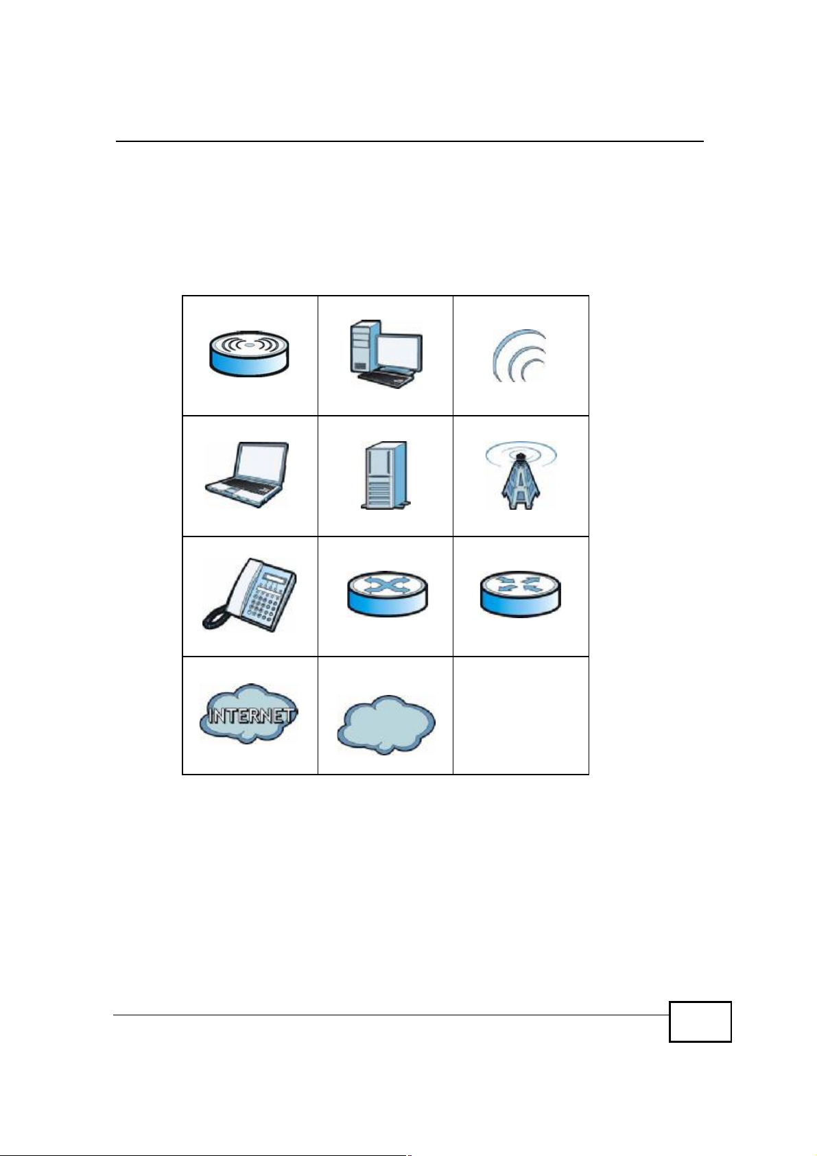
Icons Used in Figures
Figures in this User’s Guide may use the following generic icons. The OX253P icon
is not an exact representation of your OX253P.
Table 1 Common Icons
WiMAX Access PointComputerWireless Signal
NotebookServerWiMAX Base Station
TelephoneSwitchRouter
Internet CloudInternet/WiMAX
Cloud
OX253P User’s Guide
5
Page 5

Safety Warnings
• Do NOT use this product near water, for example, in a wet basement or near a
swimming pool.
• Do NOT expose your device to dampness, dust or corrosive liquids.
• Do NOT store things on the device.
• Do NOT install, use, or service this device during a thunderstorm. There is a
remote risk of electric shock from lightning.
• Connect ONLY suitable accessories to the device.
• Do NOT open the device or unit. Opening or removing covers can expose you to
dangerous high voltage points or other risks. ONLY qualified service personnel
should service or disassemble this device. Please contact your vendor for further
information.
• Make sure to connect the cables to the correct ports.
• Place connecting cables carefully so that no one will step on them or stumble
over them.
• Always disconnect all cables from this device before servicing or disassembling.
• Use ONLY an appropriate power adaptor or cord for your device. Connect it to
the right supply voltage (for example, 110V AC in North America or 230V AC in
Europe).
• Do NOT remove the plug and connect it to a power outlet by itself; always
attach the plug to the power adaptor first before connecting it to a power outlet.
• Do NOT allow anything to rest on the power adaptor or cord and do NOT place
the product where anyone can walk on the power adaptor or cord.
• Do NOT use the device if the power adaptor or cord is damaged as it might
cause electrocution.
• If the power adaptor or cord is damaged, remove it from the device and the
power source.
• Do NOT attempt to repair the power adaptor or cord. Contact your local vendor
to order a new one.Do not use the device outside, and make sure all the
connections are indoors. There is a remote risk of electric shock from lightning.
• Do NOT obstruct the device ventilation slots, as insufficient airflow may harm
your device.Use only No. 26 AWG (American Wire Gauge) or larger
telecommunication line cord.
• Antenna Warning! This device meets ETSI and FCC certification requirements
when using the included antenna(s). Only use the included antenna(s).
• If you wall mount your device, make sure that no electrical lines, gas or water
pipes will be damaged.
Safety Warnings
For your safety, be sure to read and follow all warning notices and
instructions.
6
OX253P User’s Guide
Page 6

Safety Warnings
• Make sure that the cable system is grounded so as to provide some protection
against voltage surges.
Your product is marked with this symbol, which is known as the WEEE mark. WEEE
stands for Waste Electronics and Electrical Equipment. It means that used electrical
and electronic products should not be mixed with general waste. Used electrical and
electronic equipment should be treated separately.
OX253P User’s Guide
7
Page 7

Safety Warnings
Federal
Communication
Commission
Interference
Statement
lass
B
t
o
esidential
requency
ause
hat
ause
y
he
arty
his
he
nd
hat
n
ith
This equipment has been tested and found to comply with the limits for a C
digital device, pursuant to Part 15 of the FCC Rules. These limits are designed
provide reasonable protection against harmful interference in a r
installation. This equipment generates, uses and can radiate radio f
energy and, if not installed and used in accordance with the instructions, may c
harmful interference to radio communications. However, there is no guarantee t
interference will not occur in a particular installation. If this equipment does c
harmful interference to radio or television reception, which can be determined b
turning the equipment off and on, the user is encouraged to try to correct t
interference by one of the following measures:
- Reorient or relocate the receiving antenna.
- Increase the separation between the equipment and receiver.
- Connect the equipment into an outlet on a circuit different from that
to which the receiver is connected.
- Consult the dealer or an experienced radio/TV technician for help.
FCC Caution: Any changes or modifications not expressly approved by the p
responsible for compliance could void the user's authority to operate t
equipment.
This device complies with Part 15 of the FCC Rules. Operation is subject to t
following two conditions: (1) This device may not cause harmful interference, a
(2) this device must accept any interference received, including interference t
may cause undesired operation.
IMPORTANT NOTE:
FCC Radiation Exposure Statement:
This equipment complies with FCC radiation exposure limits set forth for a
uncontrolled environment. This equipment should be installed and operated w
minimum distance 20cm between the radiator & your body.
This transmitter must not be co-located or operating in conjunction with any other
antenna or transmitter.
8
OX253P User s Guide
Page 8

Contents Overview
Contents Overview
User’s Guide ...........................................................................................................................17
Getting Started ...........................................................................................................................19
Introducing the Web Configurator ..............................................................................................23
Internet Connection Wizard....................................................................................................... 29
Tutorials .....................................................................................................................................35
Technical Reference ..............................................................................................................45
The Setup Screens ....................................................................................................................47
The LAN Configuration Screens ................................................................................................53
The WAN Configuration Screens ...............................................................................................65
The NAT Configuration Screens ................................................................................................77
The System Configuration Screens ...........................................................................................87
The Certificates Screens ...........................................................................................................97
The Firewall Screens ................................................................................................................119
Content Filter ...........................................................................................................................129
The Remote Management Screens .........................................................................................133
QoS .........................................................................................................................................145
The Logs Screens ...................................................................................................................149
The Status Screen ...................................................................................................................163
Troubleshooting .......................................................................................................................173
Product Specifications .............................................................................................................181
OX253P User’s Guide
9
Page 9

Contents Overview
10
OX253P User’s Guide
Page 10

Table of Contents
Table of Contents
About This User's Guide..........................................................................................................3
Document Conventions............................................................................................................4
Safety Warnings........................................................................................................................6
Contents Overview...................................................................................................................9
Table of Contents....................................................................................................................11
Part I: User’s Guide................................................................................17
Chapter 1
Getting Started........................................................................................................................19
1.1 About Your OX253P ............................................................................................................19
1.1.1 WiMAX Internet Access .............................................................................................19
1.2 OX253P Hardware ..............................................................................................................20
1.2.1 LEDs ..........................................................................................................................20
1.3 Good Habits for Managing the Device .................................................................................21
Chapter 2
Introducing the Web Configurator........................................................................................23
2.1 Overview ..............................................................................................................................23
2.1.1 Accessing the Web Configurator ................................................................................23
2.2 The Main Screen .................................................................................................................25
Chapter 3
Internet Connection Wizard...................................................................................................29
3.1 Overview ..............................................................................................................................29
3.1.1 Welcome to the Setup Wizard ....................................................................................29
3.1.2 System Information ....................................................................................................30
3.1.3 Authentication Settings ..............................................................................................31
3.1.4 IP Address ..................................................................................................................33
3.1.5 Setup Complete .........................................................................................................34
Chapter 4
Tutorials...................................................................................................................................35
4.1 Overview ..............................................................................................................................35
OX253P User’s Guide
11
Page 11

Table of Contents
4.2 Setting Up a Small Network .................................................................................................35
4.2.1 Connecting Your Small Network to the Internet .........................................................37
4.2.2 Changing Service Providers .......................................................................................37
4.2.3 Blocking Web Access During Specific Hours .............................................................39
4.2.4 Blocking Web Sites by Keyword ................................................................................42
4.3 Remotely Managing Your OX253P ......................................................................................44
Part II: Technical Reference..................................................................45
Chapter 5
The Setup Screens..................................................................................................................47
5.1 Overview ..............................................................................................................................47
5.1.1 What You Can Do in This Chapter .............................................................................47
5.1.2 What You Need to Know ............................................................................................47
5.1.3 Before You Begin .......................................................................................................48
5.2 Set IP Address .....................................................................................................................48
5.3 DHCP Client ........................................................................................................................49
5.4 Time Setting .........................................................................................................................50
5.4.1 Pre-Defined NTP Time Servers List ...........................................................................51
5.4.2 Resetting the Time .....................................................................................................52
Chapter 6
The LAN Configuration Screens............................................................................................53
6.1 Overview ..............................................................................................................................53
6.1.1 What You Can Do in This Chapter .............................................................................53
6.1.2 What You Need to Know ............................................................................................53
6.2 DHCP Setup ........................................................................................................................54
6.3 Static DHCP .........................................................................................................................56
6.4 IP Static Route .....................................................................................................................57
6.4.1 IP Static Route Setup .................................................................................................58
6.5 Other Settings ......................................................................................................................59
6.6 Technical Reference ............................................................................................................60
6.6.1 IP Address and Subnet Mask .....................................................................................61
6.6.2 DHCP Setup ...............................................................................................................61
6.6.3 LAN TCP/IP ................................................................................................................62
6.6.4 DNS Server Address ..................................................................................................62
6.6.5 RIP Setup ...................................................................................................................63
6.6.6 Multicast .....................................................................................................................63
Chapter 7
The WAN Configuration Screens...........................................................................................65
12
OX253P User’s Guide
Page 12

Table of Contents
7.1 Overview ..............................................................................................................................65
7.1.1 What You Can Do in This Chapter .............................................................................65
7.1.2 What You Need to Know ............................................................................................65
7.2 Internet Connection .............................................................................................................68
7.3 WiMAX Configuration ..........................................................................................................70
7.3.1 Frequency Ranges .....................................................................................................72
7.3.2 Configuring Frequency Settings .................................................................................73
7.3.3 Using the WiMAX Frequency Screen .........................................................................73
7.4 Buzzer .................................................................................................................................74
7.5 Advanced .............................................................................................................................75
Chapter 8
The NAT Configuration Screens............................................................................................77
8.1 Overview ..............................................................................................................................77
8.1.1 What You Can Do in This Chapter .............................................................................77
8.2 General ................................................................................................................................77
8.3 Port Forwarding ..................................................................................................................78
8.3.1 Port Forwarding Options ............................................................................................79
8.3.2 Port Forwarding Rule Setup .......................................................................................81
8.4 Trigger Port ..........................................................................................................................82
8.4.1 Trigger Port Forwarding Example ..............................................................................84
8.5 ALG .....................................................................................................................................85
Chapter 9
The System Configuration Screens......................................................................................87
9.1 Overview ..............................................................................................................................87
9.1.1 What You Can Do in This Chapter .............................................................................87
9.1.2 What You Need to Know ............................................................................................87
9.2 General ...............................................................................................................................89
9.3 Dynamic DNS ......................................................................................................................90
9.4 Firmware ..............................................................................................................................92
9.4.1 The Firmware Upload Process ...................................................................................93
9.5 Configuration .......................................................................................................................93
9.5.1 The Restore Configuration Process ...........................................................................94
9.6 Restart .................................................................................................................................95
9.6.1 The Restart Process ..................................................................................................95
9.7 Bridge ..................................................................................................................................95
Chapter 10
The Certificates Screens........................................................................................................97
10.1 Overview ............................................................................................................................97
10.1.1 What You Can Do in This Chapter ...........................................................................97
10.1.2 What You Need to Know ..........................................................................................97
OX253P User’s Guide
13
Page 13

Table of Contents
10.2 My Certificates ...................................................................................................................98
10.2.1 My Certificates Create ............................................................................................100
10.2.2 My Certificate Edit ..................................................................................................104
10.2.3 My Certificate Import ............................................................................................107
10.3 Trusted CAs .....................................................................................................................108
10.3.1 Trusted CA Edit ......................................................................................................110
10.3.2 Trusted CA Import ..................................................................................................113
10.4 Technical Reference .........................................................................................................113
10.4.1 Certificate Authorities ..............................................................................................114
10.4.2 Verifying a Certificate ..............................................................................................116
Chapter 11
The Firewall Screens............................................................................................................119
11.1 Overview ...........................................................................................................................119
11.1.1 What You Can Do in This Chapter ..........................................................................119
11.1.2 What You Need to Know .........................................................................................119
11.2 Firewall Setting ................................................................................................................120
11.2.1 Firewall Rule Directions ..........................................................................................120
11.2.2 Triangle Route ........................................................................................................121
11.2.3 Firewall Setting Options .........................................................................................122
11.3 Services ...........................................................................................................................123
11.4 Technical Reference ........................................................................................................124
11.4.1 Stateful Inspection Firewall. ....................................................................................124
11.4.2 Guidelines For Enhancing Security With Your Firewall ..........................................125
11.4.3 The “Triangle Route” Problem ................................................................................125
Chapter 12
Content Filter.........................................................................................................................129
12.1 Overview ..........................................................................................................................129
12.1.1 What You Can Do in This Chapter .........................................................................129
12.2 Filter .................................................................................................................................130
12.3 Schedule ..........................................................................................................................132
Chapter 13
The Remote Management Screens.....................................................................................133
13.1 Overview ..........................................................................................................................133
13.1.1 What You Can Do in This Chapter .........................................................................133
13.1.2 What You Need to Know ........................................................................................134
13.2 WWW ..............................................................................................................................135
13.3 Telnet ...............................................................................................................................136
13.4 FTP ..................................................................................................................................136
13.5 SNMP ..............................................................................................................................137
13.5.1 SNMP Traps ...........................................................................................................138
14
OX253P User’s Guide
Page 14

Table of Contents
13.5.2 SNMP Options .......................................................................................................139
13.6 DNS .................................................................................................................................140
13.7 Security ............................................................................................................................141
13.8 CWMP-TR069 .................................................................................................................142
Chapter 14
QoS.........................................................................................................................................145
14.1 Overview ..........................................................................................................................145
14.2 General ............................................................................................................................145
14.3 Class Setup .....................................................................................................................146
14.3.1 Class Configuration ................................................................................................147
Chapter 15
The Logs Screens.................................................................................................................149
15.1 Overview ..........................................................................................................................149
15.1.1 What You Can Do in This Chapter .........................................................................149
15.1.2 What You Need to Know ........................................................................................149
15.2 View Logs ........................................................................................................................151
15.3 Log Settings .....................................................................................................................153
15.4 Log Message Descriptions ..............................................................................................155
Chapter 16
The Status Screen.................................................................................................................163
16.1 Overview ..........................................................................................................................163
16.2 Status Screen ..................................................................................................................163
16.2.1 Packet Statistics .....................................................................................................167
16.2.2 WiMAX Site Information .........................................................................................168
16.2.3 DHCP Table ...........................................................................................................169
16.2.4 WiMAX Profile ........................................................................................................170
16.3 Technical Reference ........................................................................................................171
Chapter 17
Troubleshooting....................................................................................................................173
17.1 Power, Hardware Connections, and LEDs ......................................................................173
17.2 OX253P Access and Login ..............................................................................................174
17.3 Internet Access ................................................................................................................176
17.4 Export a Certificate File ...................................................................................................178
17.5 Reset the OX253P to Its Factory Defaults .......................................................................179
17.5.1 Pop-up Windows, JavaScripts and Java Permissions ...........................................179
Chapter 18
Product Specifications.........................................................................................................181
Appendix A WiMAX Security................................................................................................185
OX253P User’s Guide
15
Page 15

Table of Contents
Appendix B Setting Up Your Computer’s IP Address...........................................................189
Appendix C Pop-up Windows, JavaScripts and Java Permissions......................................217
Appendix D IP Addresses and Subnetting...........................................................................229
Appendix E Importing Certificates........................................................................................241
Appendix F Common Services.............................................................................................271
Index.......................................................................................................................................275
16
OX253P User’s Guide
Page 16

PART I
User’s Guide
17
Page 17

18
Page 18
CHAPTER 1
Getting Started
1.1 About Your OX253P
The OX253P has a built-in switch and allows you to access the Internet by
connecting to a WiMAX wireless network.
You can configure firewall and content filtering as well as a host of other features.
The web browser-based Graphical User Interface (GUI), also known as the web
configurator, provides easy management.
See Chapter 18 on page 181 for a complete list of features for your model.
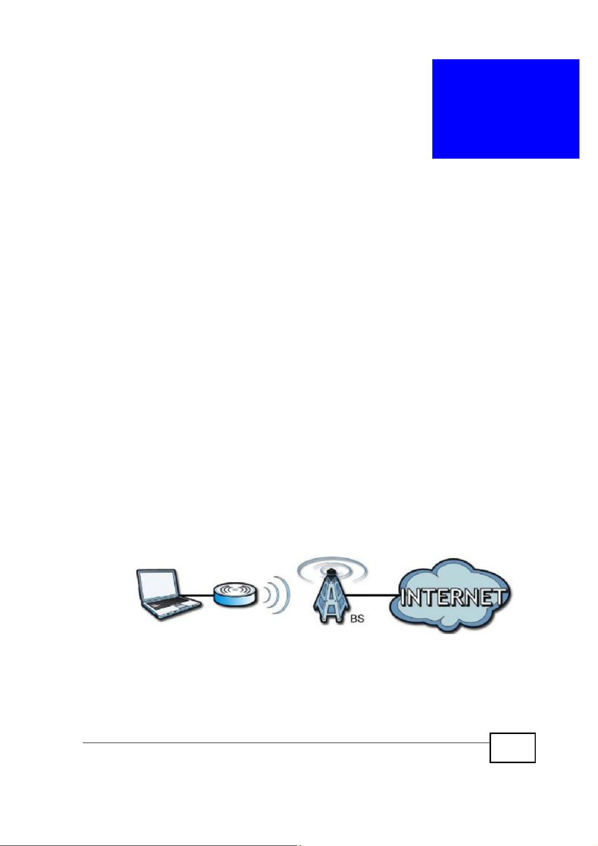
1.1.1 WiMAX Internet Access
Connect your computer or network to the OX253P for WiMAX Internet access. See
the Quick Start Guide for instructions on hardware connection.
In a wireless metropolitan area network (MAN), the OX253P connects to a WiMAX
base station (BS) for Internet access.
The following diagram shows a notebook computer equipped with the OX253P
connecting to the Internet through a WiMAX base station (marked BS).
Figure 1 Mobile Station and Base Station
When the firewall is on, all incoming traffic from the Internet to your network is
blocked unless it is initiated from your network.
Use content filtering to block access to web sites with URLs containing keywords
that you specify. You can define time periods and days during which content
OX253P User’s Guide
19
Page 19
Chapter 1Getting Started
filtering is enabled and include or exclude particular computers on your network
from content filtering. For example, you could block access to certain web sites for
the kids.
1.2 OX253P Hardware
Follow the instructions in the Quick Start Guideto make hardware connections.
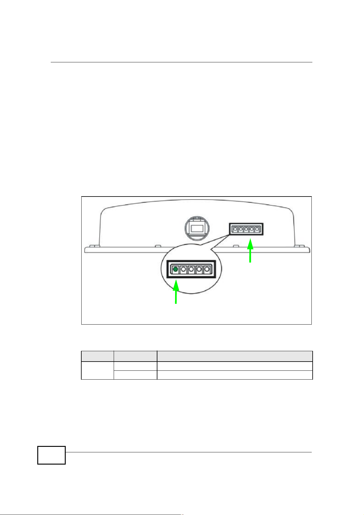
1.2.1 LEDs
The following figure shows the LEDs (lights) on the OX253P.
Figure 2 The OX253P’s LEDs
STRENGTH
INDICATORS
ACTIVITY
INDICATOR
The following table describes your OX253P’s LEDs (from right to left).
Table 2 The OX253P
LED STATE DESCRIPTION
Power
(IDU only)
OffThe OX253P is not receiving power.
GreenThe OX253P is receiving power and functioning correctly.
20
OX253P User’s Guide
Page 20

Chapter 1Getting Started
Table 2 The OX253P
LED STATE DESCRIPTION
Strength
Indicator
Activity
Indicator
The Strength Indicator LEDs display the Received Signal Strength Indication
(RSSI) of the wireless (WiMAX) connection.
5 Signal LEDsThe signal strength is greater than or equal to -59 dBm.
4 Signal LEDsThe signal strength is between -69 and -60 dBm.
3 Signal LEDsThe signal strength is between -79 and -70 dBm.
2 Signal LEDsThe signal strength is between -89 and -90 dBm.
1 Signal LEDThe signal strength is between -90 and -95 dBm.
0 Signal LEDsThere is no WiMAX connection.
OffThe OX253P is not ready.
GreenThe OX253P is connected to the network.
BlinkingThe OX253P system is booting up or the OX253P is seeking
a viable signal.
1.3 Good Habits for Managing the Device
Do the following things regularly to make the OX253P more secure and to manage
the OX253P more effectively.
• Change the password. Use a password that’s not easy to guess and that consists
of different types of characters, such as numbers and letters.
• Write down the password and put it in a safe place.
• Back up the configuration (and make sure you know how to restore it).
Restoring an earlier working configuration may be useful if the OX253P becomes
unstable or even crashes. If you forget your password, you will have to reset the
OX253P to its factory default settings. If you backed up an earlier configuration
file, you would not have to totally re-configure the OX253P. You could simply
restore your last configuration.
OX253P User’s Guide
21
Page 21

Chapter 1Getting Started
22
OX253P User’s Guide
Page 22

CHAPTER 2
Introducing the Web
Configurator
2.1 Overview
The web configurator is an HTML-based management interface that allows easy
device set up and management via any web browser that supports: HTML 4.0,
CSS 2.0, and JavaScript 1.5, and higher. The recommended screen resolution for
using the web configurator is 1024 by 768 pixels and 16-bit color, or higher.
In order to use the web configurator you need to allow:
• Web browser pop-up windows from your device. Web pop-up blocking is enabled
by default in many operating systems and web browsers.
• JavaScript (enabled by default in most web browsers).
• Java permissions (enabled by default in most web browsers).
See the Appendix C on page 217 for more information on configuring your web
browser.
2.1.1 Accessing the Web Configurator
1 Make sure your OX253P hardware is properly connected (refer to the Quick Start
Guide for more information).
2 Launch your web browser.
3 Enter "192.168.1.1" as the URL.
4 Select your preferable language from the language drop-down list.
OX253P User’s Guide
23
Page 23
Chapter 2Introducing the Web Configurator
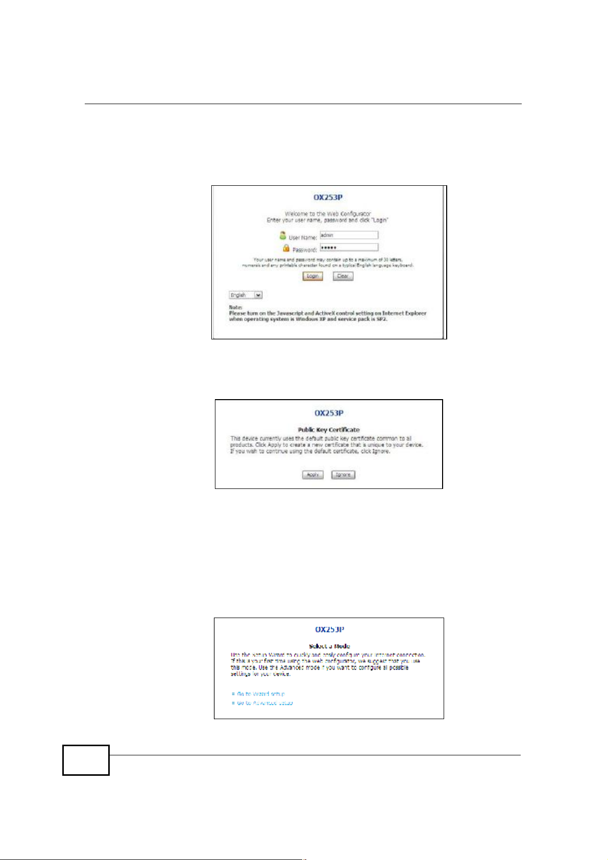
5 A password screen displays. Enter the default username (admin) and password
(admin) and then click Login. Click Cancel to revert to the default password in
the password field. If you have changed the password, enter your password and
click Login.
6 The following screen displays. Click Apply to have the OX253P generate a new
certificate. You can also click Ignore to have the OX253P use the default
certificate.
24
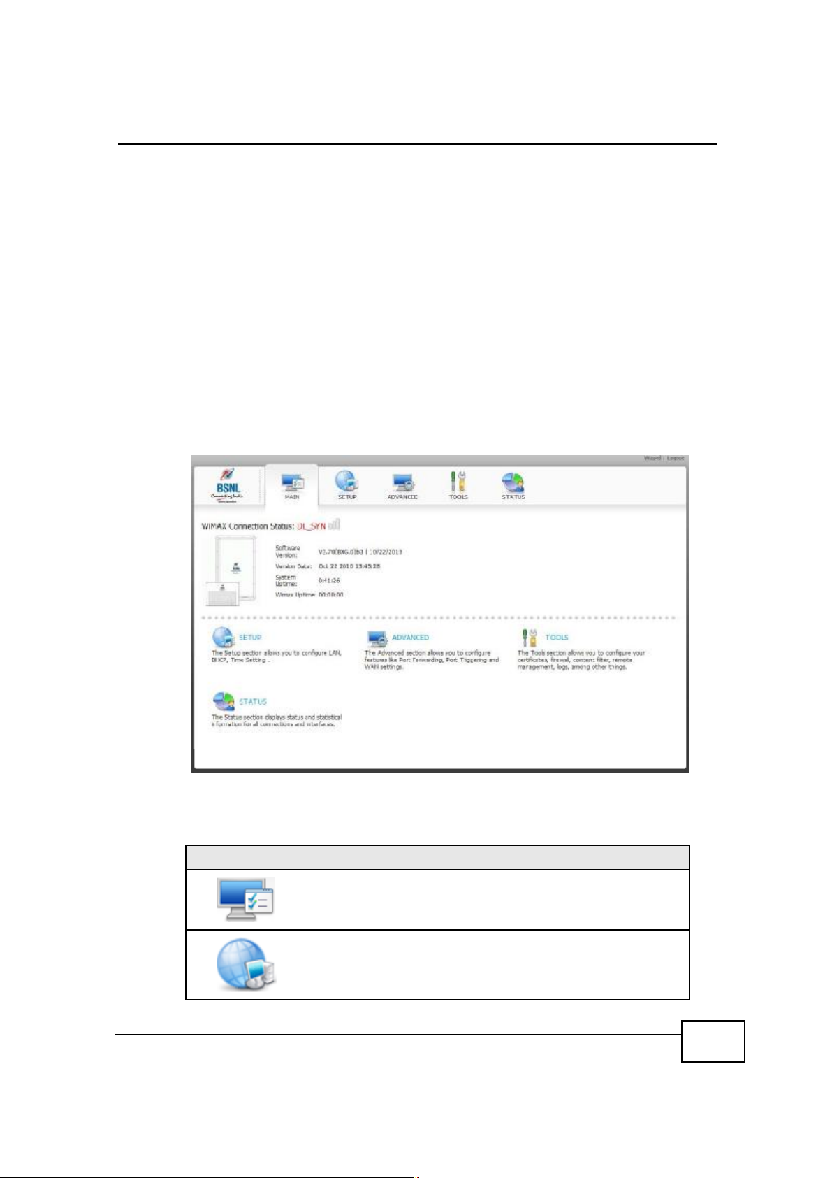
7 A screen displays to let you choose to go to the Wizard or the Advanced screens.
• Click Go to Wizard setup if you are logging in for the first time or if you
want to make basic changes. The wizard selection screen appears. See
Chapter 3 on page 29 for more information.
• Click Go to Advanced setup if you want to configure features that are not
available in the wizards. The main screen appears. See Section 16.2 on
page 163 for more information.
• Click Exit if you want to log out.
OX253P User’s Guide
Page 24
Note: For security reasons, the OX253P automatically logs you out if you do not use
the Web Configurator for five minutes. If this happens, log in again.
2.2 The Main Screen
When you first log into the web configurator and by-pass the wizard, the Main
screen appears. Here you can view a summary of your OX253P connection status.
This is also the default “home” page for the web configurator and it contains
conveniently-placed shortcuts to all of the other screens.
Note: Some features in the web configurator may not be available depending on your
firmware version and/or configuration.
Figure 3 Main Screen
Chapter 2Introducing the Web Configurator
The following table describes the icons in this screen.
Table 3 Main > Icons
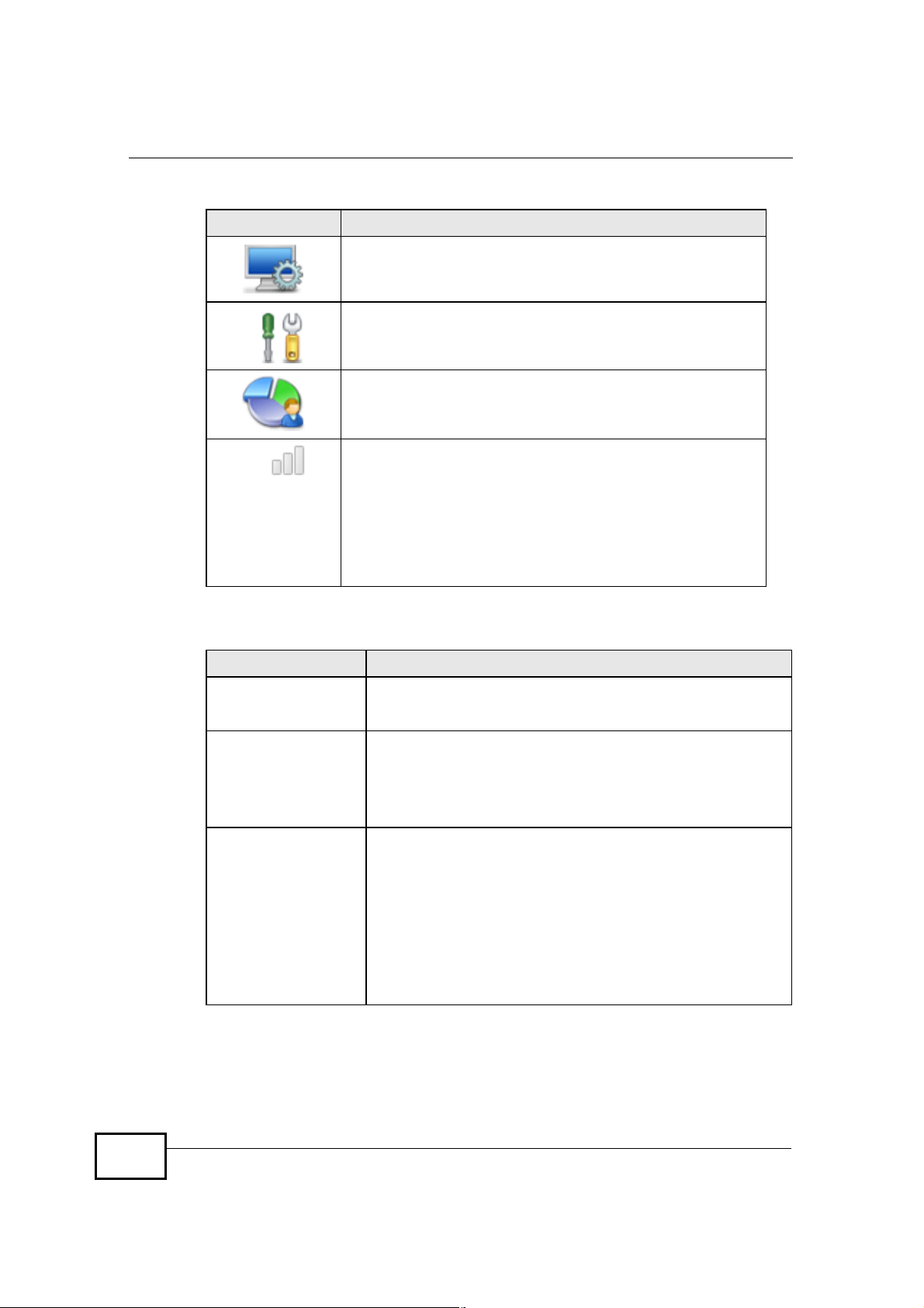
ICON DESCRIPTION
OX253P User’s Guide
MAIN
Click to return to the Main screen.
SETUP
Click to go the Setup screen, where you can configure LAN,
DHCP and WAN settings.
25
Page 25
Chapter 2Introducing the Web Configurator
Table 3 Main > Icons (continued)
ICON DESCRIPTION
ADVANCED
Click to go to the Advanced screen, where you can configure
features like Port Forwarding and Triggering, SNTP and so on.
TOOLS
Click to go the Tools screen, where you can configure your
firewall, QoS, and content filter, among other things.
STATUS
Click to go to the Status screen, where you can view status and
statistical information for all connections and interfaces.
Strength Indicator
Displays a visual representation of the quality of your WiMAX
connection.
• Disconnected - Zero bars
• Poor reception - One bar
• Good reception - Two bars
• Excellent reception - Three bars
The following table describes the labels in this screen.
Table 4 Main
LABEL DESCRIPTION
WizardClick to run the Internet Connection Setup Wizard. All of the
settings that you can configure in this wizard are also available
in these web configurator screens.
LogoutClick to log out of the web configurator.
Note: This does not log you off the WiMAX network, it simply
logs you out of the OX253P’s browser-based
configuration interface.
WiMAX Connection
Status
This field indicates the current status of your WiMAX connection.
Status messages are as follows:
• Connected - Indicates that the OX253P is connected to the
WiMAX network. Use the Strength Indicator icon to
determine the quality of your network connection.
• Disconnected - Indicates that the OX253P is not connected
to the WiMAX network.
• DL_SYN - Indicates a download synchronization is in
progress. This means the firmware is checking with the
server for any updates or settings alterations.
26
OX253P User’s Guide
Page 26

Chapter 2Introducing the Web Configurator
Table 4 Main (continued)
LABEL DESCRIPTION
Software VersionThis field indicates the version number of the OX253P’s
firmware. The version number takes the form of:
Version(Build),release status (candidate) | Version Release
Date.
For example: V3.70(TPG.0)c4 | 07/08/2010 indicates that the
firmware is 3.70, build TPG.0, candidate 4, released on July 08,
2010.
Version DateThis field indicates the exact date and time the current firmware
was compiled.
System UptimeThis field indicates how long the OX253P has been on. This
resets every time you shut the device down or restart it.
WiMAX UptimeThis field indicates how long the OX253P has been connected to
the WiMAX network. This resets every time you disconnect from
the WiMAX network, shut the device down, or restart it.
OX253P User’s Guide
27
Page 27

Chapter 2Introducing the Web Configurator
28
OX253P User’s Guide
Page 28
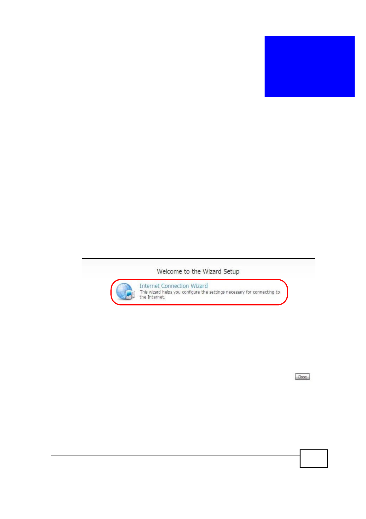
CHAPTER 3
Internet Connection Wizard
3.1 Overview
This chapter provides information on the Setup Wizard screens. The wizard guides
you through several steps where you can configure your Internet settings.
3.1.1 Welcome to the Setup Wizard
This is the welcome screen for the Setup Wizard.
The Internet Connection Wizard screens are described in detail in the following
sections.
Figure 4 Select a Mode
OX253P User’s Guide
29
Page 29
Chapter 3Internet Connection Wizard
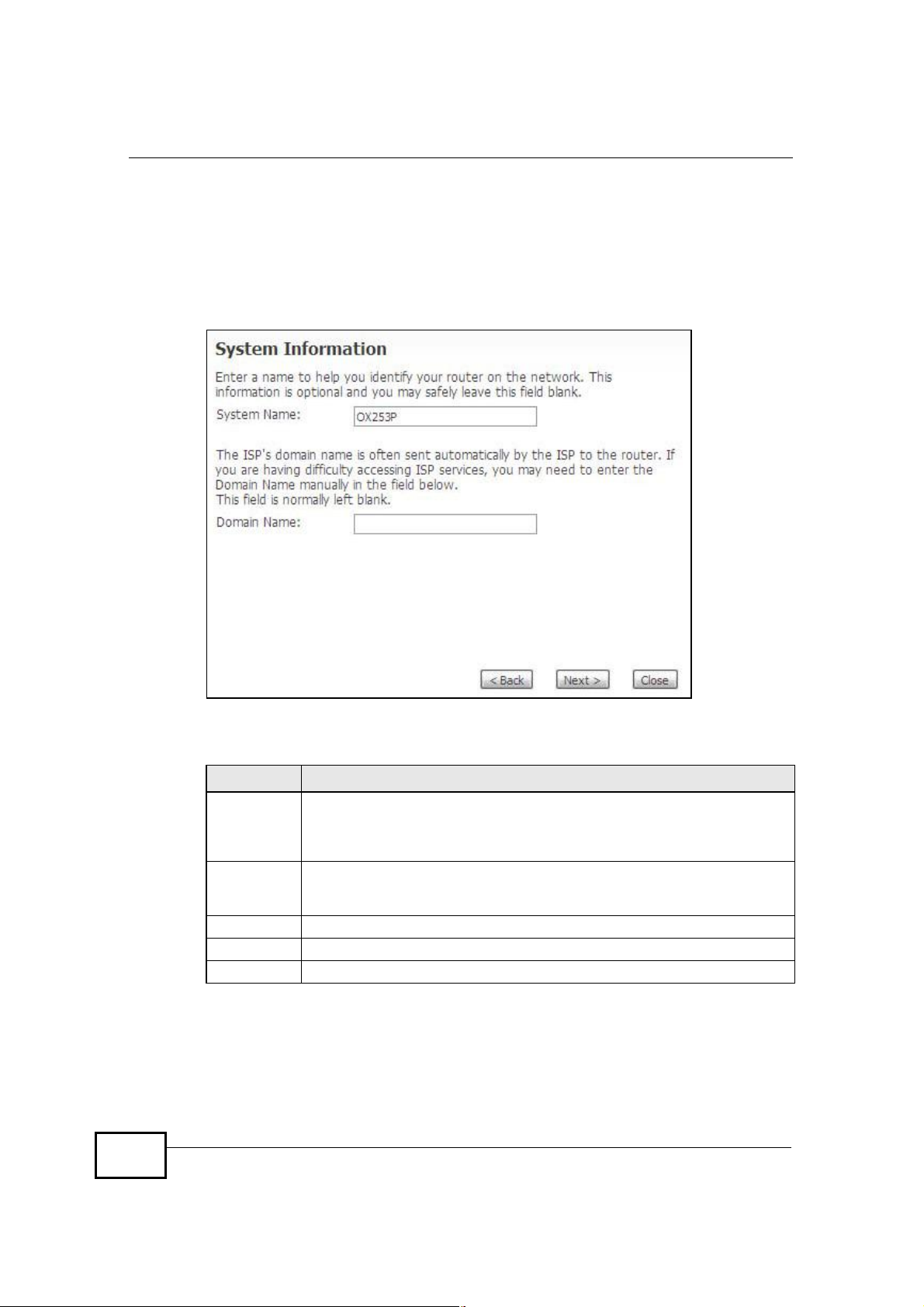
3.1.2 System Information
This Internet Connection Wizard screen allows you to configure your OX253P’s
system information. The settings here correspond to the ADVANCED > System
Configuration > General screen (see Section 9.2 on page 89 for more).
Figure 5 Internet Connection Wizard > System Information
30
The following table describes the labels in this screen.
Table 5 Internet Connection Wizard > System Information
LABEL DESCRIPTION
System
Name
Domain
Name
Back Click to display the previous screen.
Next Click to proceed to the next screen.
Close Click to close the wizard without saving.
System Name is a unique name to identify the OX253P in an Ethernet
network. Enter a descriptive name. This name can be up to 30
alphanumeric characters long. Spaces are not allowed, but dashes "-" and
underscores "_" are accepted.
Type the domain name (if you know it) here. If you leave this field blank,
the ISP may assign a domain name via DHCP. The domain name entered
by you is given priority over the ISP assigned domain name.
OX253P User’s Guide
Page 30

3.1.3 Authentication Settings
This Internet Connection Wizard screen allows you to configure your Internet
access settings. The settings here correspond to the ADVANCED > WAN
Configuration > Internet Connection screen (see Section 7.2 on page 68 for
more information).
Figure 6 Internet Connection Wizard > Authentication Settings Screen
Chapter 3Internet Connection Wizard
The following table describes the labels in this screen.
Table 6 Internet Connection Wizard > Authentication Settings Screen
LABEL DESCRIPTION
User NameUse this field to enter the username associated with your Internet
PasswordUse this field to enter the password associated with your Internet access
Anonymous
Identity
PKMThis field displays the Privacy Key Management version number. PKM
OX253P User’s Guide
access account. You can enter up to 61 printable ASCII characters.
account. You can enter up to 47 printable ASCII characters.
Enter the anonymous identity provided by your Internet Service
Provider. Anonymous identity (also known as outer identity) is used with
EAP-TTLS encryption. The anonymous identity is used to route your
authentication request to the correct authentication server, and does not
reveal your real user name. Your real user name and password are
encrypted in the TLS tunnel, and only the anonymous identity can be
seen.
Leave this field blank if your ISP did not give you an anonymous identity
to use.
provides security between the OX253P and the base station. At the time
of writing, the OX253P supports PKMv2 only. See the WiMAX security
appendix for more information.
31
Page 31

Chapter 3Internet Connection Wizard
Table 6 Internet Connection Wizard > Authentication Settings Screen (continued)
LABEL DESCRIPTION
AuthenticationThis field displays the user authentication method. Authentication is the
process of confirming the identity of a mobile station (by means of a
username and password, for example).
Check with your service provider if you are unsure of the correct setting
for your account.
Choose from the following user authentication methods:
• TTLS (Tunnelled Transport Layer Security)
• TLS (Transport Layer Security)
Note: Not all OX253Ps support TLS authentication. Check with your
TTLS Inner EAPThis field displays the type of secondary authentication method. Once a
secure EAP-TTLS connection is established, the inner EAP is the protocol
used to exchange security information between the mobile station, the
base station and the AAA server to authenticate the mobile station. See
the WiMAX security appendix for more details. The OX253P supports the
following inner authentication types:
• CHAP (Challenge Handshake Authentication Protocol)
• MSCHAP (Microsoft CHAP)
• MSCHAPV2 (Microsoft CHAP version 2)
• PAP (Password Authentication Protocol)
CertificateThis is the security certificate the OX253P uses to authenticate the AAA
server. Use the TOOLS > Certificates > Trusted CA screen to import
certificates to the OX253P.
Back Click to display the previous screen.
Next Click to proceed to the next screen.
Close Click to close the wizard without saving.
service provider for details.
32
OX253P User’s Guide
Page 32

3.1.4 IP Address
This Internet Connection Wizard screen allows you to configure your IP address.
The settings here correspond to the SETUP > Set IP Address screen (see
Section 5.2 on page 48).
A fixed IP address is a static IP that your ISP gives you. An automatic (dynamic)
IP address is not fixed; the ISP assigns you a different one each time you connect
to the Internet.
Figure 7 Internet Connection Wizard > IP Address
Chapter 3Internet Connection Wizard
The following table describes the labels in this screen.
Table 7 Internet Connection Wizard > IP Address
LABEL DESCRIPTION
IP Address
My computer or device
gets its IP address
automatically from the
network
Use fixed IP AddressA static IP address is a fixed IP that your ISP gives you.
BackClick to display the previous screen.
Next Click to proceed to the next screen.
Close Click to close the wizard screen without saving.
OX253P User’s Guide
Select this if you have a dynamic IP address. A dynamic IP
address is not fixed; the ISP assigns you a different one each
time you connect to the Internet.
33
Page 33

Chapter 3Internet Connection Wizard
3.1.5 Setup Complete
Click Close to complete and save the Internet Connection Wizard settings.
Figure 8 Internet Connection Wizard > Complete
Launch your web browser and navigate to a website of your choice . If everything
was configured properly, the web page should display. You can now surf the
Internet!
Refer to the rest of this guide for more detailed information on the complete range
of OX253P features available in the more advanced web configurator.
Note: If you cannot access the Internet, open the web configurator again to confirm
that the Internet settings you configured in the wizard setup are correct.
34
OX253P User’s Guide
Page 34

CHAPTER 4
Tutorials
4.1 Overview
This chapter shows you how to configure some of the OX253P’s features.
Note: Be sure to read Introducing the Web Configurator on page 23 before working
through the tutorials presented here. For field descriptions of individual screens,
see the related technical reference in this User's Guide.
4.2 Setting Up a Small Network
This tutorial shows you how to set up a small network in your office or home.
Goal: Connect three computers to your OX253P to form a small network.
OX253P User’s Guide
35
Page 35

Chapter 4Tutorials
Required: The following table provides a summary of the information you will
need to complete the tasks in this tutorial.
INFORMATION VALUE SEE ALSO
LAN IP Address192.168.100.1 Chapter 5 on page 47
Starting IP Address192.168.100.33 Chapter 6 on page 53
Pool Size32
DNS ServersFrom ISP
1 In the Web Configurator, open the SETUP > Set IP Address screen and set the
IP Address to 192.168.100.1. Use the default IP Subnet Mask of 255.255.255.0.
2 Open the ADVANCED > LAN Configuration > DHCP Setup screen.
36
3 Select Enable DHCP Server, then enter 192.168.100.34 as your IP Pool
Starting Address and 32 for your Pool Size.
4 In the DNS Server section, set the First, Second and Third DNS Server fields
to From ISP in order to use the DNS servers linked to your ISP.
5 Click Apply to save your DHCP settings.
OX253P User’s Guide
Page 36

Chapter 4Tutorials
6 Next, go to the ADVANCED > NAT Configuration > General screen and select
the Enable Network Address Translation option.
7 Click Apply to save your settings.
8 Connect your computers to the OX253P’s Ethernet ports and you’re all set!
Note: You may need to configure the computers on your LAN to automatically obtain
IP addresses. For information on how to do this, see Appendix B on page 189.
4.2.1 Connecting Your Small Network to the Internet
Once your network is configured and hooked up, you will want to connect it to the
Internet next. To do this, just run the Internet Connection Wizard (Chapter 3
on page 29), which walks you through the process.
4.2.2 Changing Service Providers
This tutorial shows you how to import a new security certificate, which allows your
device to communicate with the company’s network servers. This is necessary if
you ever change Internet Service Providers and your OX253P is still compatible
with the new network. (In some cases it may not be.)
Goal: Import a new security certificate into the OX253P.
See Also: Chapter 10 on page 97.
OX253P User’s Guide
37
Page 37

Chapter 4Tutorials
1 In the Web Configurator, open the TOOLS > Certificates > My Certificates
screen and click the Import button.
2 In the Import Certificate screen, click Browse andlocate the security certificate
that was provided by your new ISP.
38
OX253P User’s Guide
Page 38

Chapter 4Tutorials
3 Next, go to the ADVANCED > WAN Configuration screen and configure your
new Internet access settings based on the information provided by your ISP.
Note: You can also use the Internet Connection Wizard to configure these settings.
4 From the Certificates menu, select the security certificate that you just imported.
5 Click Apply to save your settings. You should now be able to connect to the
Internet through your new service provider!
4.2.3 Blocking Web Access During Specific Hours
If your OX253P is in a home or office environment you may decide that you want
to block web access and video chat during a specific block of hours, such as during
your daughter’s designated study hours.
Goal: Configure the OX253P’s firewall to block web and video chat access on
weekdays between the hours of 3:30 PM and 8:30 PM.’
See Also: Chapter 11 on page 119.
OX253P User’s Guide
39
Page 39

Chapter 4Tutorials
1 Open the TOOLS > Firewall > Services to screen.
2 Select Enable Services Blocking.
40
OX253P User’s Guide
Page 40

Chapter 4Tutorials
3 Under Available Services, select HTTP(TCP:80) then click the Add button.
Repeat this for CU-SEEME(TCP/UDP:7648,24032).
This blocks all web and video chat traffic, while leaving other ports open for other
types of traffic, such as ports 25 and 587 for e-mail and port 21 for FTP.
The Blocked Services window updates accordingly.
4 Next, configure the Schedule to Block area with the days and hours for blocking
web access to your employees.
In this example, the five weekly work days are selected as well as the standard
work hours of 3:30 PM to 8:30 PM (or 20:30 in 24-hour format).
5 Finally, click Apply to save your settings.
OX253P User’s Guide
41
Page 41

Chapter 4Tutorials
4.2.4 Blocking Web Sites by Keyword
You can further refine web access by specifying keywords that appear in a URL
and blocking them. This allows you to control the content you do allow to pass
through the OX253P. For example, once your daughter’s designated study hours
end, you allow web access and video chat but want to restrict certain sites.
Goal: Restrict websites with the words “poker”, “sex”, and “beer” in their URLs.
See Also: Chapter 12 on page 129.
1 Open the TOOLS > Content Filter > Filter screen.
42
2 Select Enable URL Keyword Blocking.
OX253P User’s Guide
Page 42

Chapter 4Tutorials
3 Enter the first Keyword then click Add. Repeat for additional keywords.
As you enter them, the keywords appear in the Keyword List.
4 (Optional) If you want to allow websites with these keywords for a specific
computer in your household, such as the computer in the master bedroom, then
add that computer’s IP address to the Trusted IP Address field.
5 Click Apply to save these settings.
6 Next, open the TOOLS > Content Filter > Schedule screen.
7 To keep things simple, set the Days to Block to Everyday and the Time of Day
to Block to All Day.
8 Click Apply to save these settings.
OX253P User’s Guide
43
Page 43

Chapter 4Tutorials
4.3 Remotely Managing Your OX253P
The remote management feature allows you to log into the device over the
Internet and configure its settings from a second trusted location.
Goal: Set up the OX253P to allow management requests from the
(demonstration) IP address 2.2.2.2.
See Also: Chapter 13 on page 133.
1 Open the TOOLS > Remote Management > WWW screen.
2 Leave the Server Port setting as ‘80’, in order to allow computers back at the
OX253P’s location to continue to access the Internet.
3 From the Server Access menu, select WAN. This allows remote management
connections only from the Internet.
4 Finally, in the Secured Client IP Address field enter 2.2.2.2 as the IP address
from which you will be connecting to the OX253P. Any other attempts by
computer on the Internet to connect will be rejected because their IP addresses
won’t match the one specified here.
5 Click Apply to save your changes.
44
OX253P User’s Guide
Page 44

PART II
Technical Reference
45
Page 45

46
Page 46

CHAPTER 5
The Setup Screens
5.1 Overview
Use these screens to configure or view LAN, DHCP Client and WAN settings.
5.1.1 What You Can Do in This Chapter
• The Set IP Address screen (Section 5.2 on page 48) lets you configure the
OX253P’s IP address and subnet mask.
• The DHCP Client screen (Section 5.3 on page 49) to view connection
information for clients configured by the OX253P’s internal DHCP server.
• The Time Setting screen (Section 5.4 on page 50) lets you configure your
OX253P’s time and date keeping settings.
5.1.2 What You Need to Know
The following terms and concepts may help as you read through this chapter.
LAN
A Local Area Network, or a shared communication system to which many
computers are attached. A LAN, as its name implies, is limited to a local area such
as a home or office environment. LANs have different topologies, the most
common being the linear bus and the star configuration.
IP Address
IP addresses identify individual devices on a network. Every networking device
(including computers, servers, routers, printers, etc.) needs an IP address to
communicate across the network. These networking devices are also known as
hosts.
Subnet Mask
The subnet mask specifies the network number portion of an IP address. Your
device will compute the subnet mask automatically based on the IP Address that
OX253P User’s Guide
47
Page 47

Chapter 5The Setup Screens
you entered. You do not need to change the computer subnet mask unless you are
instructed to do so.
Daytime
A network protocol used by devices for debugging and time measurement. A
computer can use this protocol to set its internal clock but only if it knows in which
order the year, month, and day are returned by the server. Not all servers use the
same format.
Time
A network protocol for retrieving the current time from a server. The computer
issuing the command compares the time on its clock to the information returned
by the server, adjusts itself automatically for time zone differences, then
calculates the difference and corrects itself if there has been any temporal drift.
NTP
NTP stands for Network Time Protocol. It is employed by devices connected to the
Internet in order to obtain a precise time setting from an official time server.
These time servers are accurate to within 200 microseconds.
5.1.3 Before You Begin
• Make sure that you have made all the appropriate hardware connections to the
OX253P, as described in the Quick Start Guide.
• Make sure that you have logged in to the web configurator at least one time and
changed your password from the default, as described in the Quick Start Guide.
5.2 Set IP Address
Click the SETUP icon in the navigation bar to set up the OX253P’s IP address and
subnet mask. This screen displays this screen by default. If you are in any other
sub-screen you can simply choose Set IP Address from the navigation menu on
the left to open it again.
Figure 9 SETUP > Set IP Address
48
OX253P User’s Guide
Page 48

The following table describes the labels in this screen.
Table 8 SETUP > Set IP Address
LABEL DESCRIPTION
IP Address Enter the IP address of the OX253P on the LAN.
IP Subnet Mask Enter the subnet mask of the LAN.
Apply Click to save your changes.
Reset Click to restore your previously saved settings.
5.3 DHCP Client
Chapter 5The Setup Screens
Note: This field is the IP address you use to access the
OX253P on the LAN. If the web configurator is running
on a computer on the LAN, you lose access to it as
soon as you change this field and click Apply. You can
access the web configurator again by typing the new
IP address in the browser.
Click the SETUP > DHCP Client to view connection information for all clients that
have been configured by the OX253P’s internal DHCP server.
Figure 10 SETUP > Set IP Address
The following table describes the labels in this screen.
Table 9 SETUP > Set IP Address
LABEL DESCRIPTION
#This indicates the number of the item in this list.
IP Address This indicates the IP address of a connected client device.
Host Name This indicates the host name of a connected client device. If the
device is computer, then the host name is the computer name.
MAC Address This indicates the MAC address of a connected client device.
OX253P User’s Guide
49
Page 49

Chapter 5The Setup Screens
Table 9 SETUP > Set IP Address (continued)
LABEL DESCRIPTION
Reserve This indicates whether the IP address for the connected client
Apply Click to save your changes.
Refresh Click to refresh the information in the screen.
5.4 Time Setting
Click SETUP >Time Setting to set the date, time, and time zone for the
OX253P.
Figure 11 SETUP > Time Setting
device is reserved. When the DHCP server issues IP addresses,
reserved IPs are assigned to specific client devices.
If the IP address is reserved, the client device identified by its
MAC address will always receive this IP address from the DHCP
server.
50
The following table describes the labels in this screen.
Table 10 SETUP > Time Setting
LABEL DESCRIPTION
Current Time and Date
Current TimeDisplays the current time according to the OX253P.
OX253P User’s Guide
Page 50

Chapter 5The Setup Screens
Table 10 SETUP > Time Setting (continued)
LABEL DESCRIPTION
Current DateDisplays the current time according to the OX253P.
Time and Date Setup
Manual Select this if you want to specify the current date and time in the
New Time Enter the new time in this field, and click Apply.
New Date Enter the new date in this field, and click Apply.
Get from Time Server Select this if you want to use a time server to update the current
Time ProtocolSelect the time service protocol that your time server
Time Server
Address
Time Zone Setup
Time ZoneSelect the time zone at your location.
Daylight SavingsSelect this if your location uses daylight savings time. Daylight
Start DateEnter which hour on which day of which week of which month
End DateEnter which hour on the which day of which week of which
Apply Click to save your changes.
Reset Click to restore your previously saved settings.
fields below.
date and time in the OX253P.
uses.Check with your ISP or network administrator, or use trialand-error to find a protocol that works.
Daytime (RFC-867) - This format is day/month/year/time
zone.
Time (RFC-868) - This format displays a 4-byte integer giving
the total number of seconds since 1970/1/1 at 0:0:0.
NTP (RFC-1305) - This format is similar to Time (RFC 868).
Enter the IP address or URL of your time server. Check with your
ISP or network administrator if you are unsure of this
information.
savings is a period from late spring to early fall when many
places set their clocks ahead of normal local time by one hour to
give more daytime light in the evening.
daylight-savings time starts.
month daylight-savings time ends.
5.4.1 Pre-Defined NTP Time Servers List
The OX253P uses a pre-defined list of NTP time servers if you do not specify a
time server or it cannot synchronize with the time server you specified. It can use
this list regardless of the time protocol you select.
When the OX253P uses the list, it randomly selects one server and tries to
synchronize with it. If the synchronization fails, then it goes through the rest of
OX253P User’s Guide
51
Page 51

Chapter 5The Setup Screens
the list in order until either it is successful or all the pre-defined NTP time servers
have been tried.
Table 11 Pre-defined NTP Time Servers
ntp1.cs.wisc.edu
ntp1.gbg.netnod.se
ntp2.cs.wisc.edu
tock.usno.navy.mil
ntp3.cs.wisc.edu
ntp.cs.strath.ac.uk
ntp1.sp.se
time1.stupi.se
tick.stdtime.gov.tw
tock.stdtime.gov.tw
time.stdtime.gov.tw
5.4.2 Resetting the Time
The OX253P automatically resets the time in the following circumstances:
• When the device starts up, such as when you press the Power button.
• When you click Apply in the SETUP > Time Setting screen.
• Once every 24-hours after starting up.
52
OX253P User’s Guide
Page 52

CHAPTER 6
The LAN Configuration Screens
6.1 Overview
Use the ADVANCED > LAN Configuration screens to set up the OX253P on the
LAN. You can configure its IP address and subnet mask, DHCP services, and other
subnets. You can also control how the OX253P sends routing information using
RIP.
A Local Area Network (LAN) is a shared communication system to which many
computers are attached. A LAN is usually a computer network limited to the
immediate area, such as the same building or floor of a building.
6.1.1 What You Can Do in This Chapter
• The DHCP Setup screen (Section 6.2 on page 54) lets you enable, disable, and
configure the DHCP server in the OX253P.
• The Static DHCP screen (Section 6.3 on page 56) lets you assign specific IP
addresses to specific computers on the LAN.
• The IP Static Route screen (Section 6.4 on page 57) lets you examine the
static routes configured in the OX253P.
• The Other Settings screen (Section 6.5 on page 59) lets you control the
routing information that is sent and received by each subnet assign specific IP
addresses to specific computers on the LAN.
6.1.2 What You Need to Know
The following terms and concepts may help as you read through this chapter.
IP Address
IP addresses identify individual devices on a network. Every networking device
(including computers, servers, routers, printers, etc.) needs an IP address to
communicate across the network. These networking devices are also known as
hosts.
OX253P User’s Guide
53
Page 53

Chapter 6The LAN Configuration Screens
Subnet Masks
Subnet masks determine the maximum number of possible hosts on a network.
You can also use subnet masks to divide one network into multiple sub-networks.
DNS
DNS (Domain Name System) is for mapping a domain name to its corresponding
IP address and vice versa. The DNS server is extremely important because
without it, you must know the IP address of a networking device before you can
access it.
DHCP
A DHCP (Dynamic Host Configuration Protocol) server can assign your OX253P an
IP address, subnet mask, DNS and other routing information when it’s turned on.
6.2 DHCP Setup
Click ADVANCED > LAN Configuration > DHCP Setup to enable, disable, and
configure the DHCP server in the OX253P.
Figure 12 ADVANCED > LAN Configuration > DHCP Setup
The following table describes the labels in this screen.
Table 12 ADVANCED > LAN Configuration > DHCP Setup
LABEL DESCRIPTION
DHCP Setup
Enable DHCP
Server
Select this if you want the OX253P to be the DHCP server on the LAN.
As a DHCP server, the OX253P assigns IP addresses to DHCP clients on
the LAN and provides the subnet mask and DNS server information.
54
OX253P User’s Guide
Page 54

Chapter 6The LAN Configuration Screens
Table 12 ADVANCED > LAN Configuration > DHCP Setup (continued)
LABEL DESCRIPTION
IP Pool Starting
Address
Pool Size Enter the number of IP addresses to allocate. This number must be at
DNS Server
First, Second
and Third DNS
Server
Apply Click to save your changes.
Reset Click to restore your previously saved settings.
Enter the IP address from which the OX253P begins allocating IP
addresses, if you have not specified an IP address for this computer in
ADVANCED > LAN Configuration > Static DHCP.
least one and is limited by a subnet mask of 255.255.255.0 (regardless
of the subnet the OX253P is in). For example, if the IP Pool Start
Address is 10.10.10.10, the OX253P can allocate up to 10.10.10.254,
or 245 IP addresses.
Specify the IP addresses of a maximum of three DNS servers that the
network can use. The OX253P provides these IP addresses to DHCP
clients. You can specify these IP addresses two ways.
From ISP - provide the DNS servers provided by the ISP on the WAN
port.
User Defined - enter a static IP address.
DNS Relay - this setting will relay DNS information from the DNS
server obtained by the OX253P.
None - no DNS service will be provided by the OX253P.
OX253P User’s Guide
55
Page 55

Chapter 6The LAN Configuration Screens
6.3 Static DHCP
Click ADVANCED > LAN Configuration > Static DHCP to assign specific IP
addresses to specific computers on the LAN.
Note: This screen has no effect if the DHCP server is not enabled. You can enable it
in ADVANCED > LAN Configuration > DHCP Setup.
Figure 13 ADVANCED > LAN Configuration > Static DHCP
56
The following table describes the labels in this screen.
Table 13 ADVANCED > LAN Configuration > Static DHCP
LABEL DESCRIPTION
#The number of the item in this list.
MAC Address Enter the MAC address of the computer to which you want the OX253P
to assign the same IP address.
IP Address Enter the IP address you want the OX253P to assign to the computer.
Apply Click to save your changes.
Reset Click to restore your previously saved settings.
OX253P User’s Guide
Page 56

6.4 IP Static Route
Click ADVANCED > LAN Configuration > IP Static Route to look at the static
routes configured in the OX253P.
Note: The first static route is the default route and cannot be modified or deleted.
Figure 14 Advanced> LAN Configuration > IP Static Route
Chapter 6The LAN Configuration Screens
The following table describes the icons in this screen.
Table 14 Advanced> LAN Configuration > IP Static Route
ICON DESCRIPTION
The following table describes the labels in this screen.
Table 15 Advanced> LAN Configuration > IP Static Route
LABEL DESCRIPTION
# The number of the item in this list.
Name This field displays the name that describes the static route.
OX253P User’s Guide
Edit
Click to edit this item.
Delete
Click to delete this item.
57
Page 57

Chapter 6The LAN Configuration Screens
Table 15 Advanced> LAN Configuration > IP Static Route (continued)
LABEL DESCRIPTION
Active This field shows whether this static route is active (Yes) or not (No).
Destination This field displays the destination IP address(es) that this static route
Gateway This field displays the IP address of the gateway to which the OX253P
Action Click the Edit icon to modify this item.
affects.
should send packets for the specified Destination. The gateway is a
router or a switch on the same network segment as the device's LAN or
WAN port. The gateway helps forward packets to their destinations.
Click the Delete icon to remove this item.
6.4.1 IP Static Route Setup
Click an Edit icon in ADVANCED > LAN Configuration > IP Static Route to
edit a static route in the OX253P.
Figure 15 Advanced> LAN Configuration > IP Static Route Setup > Edit
58
The following table describes the labels in this screen.
Table 16 Advanced> LAN Configuration > IP Static Route Setup > Edit
LABEL DESCRIPTION
Route Name Enter the name of the static route.
Active Select this if you want the static route to be used. Clear this if you do
not want the static route to be used.
Private Select this if you do not want the OX253P to tell other routers about this
static route. For example, you might select this if the static route is in
your LAN. Clear this if you want the OX253P to tell other routers about
this static route.
Destination IP
Address
Enter one of the destination IP addresses that this static route affects.
OX253P User’s Guide
Page 58

Chapter 6The LAN Configuration Screens
Table 16 Advanced> LAN Configuration > IP Static Route Setup > Edit (continued)
LABEL DESCRIPTION
IP Subnet Mask Enter the subnet mask that defines the range of destination IP
addresses that this static route affects. If this static route affects only
one IP address, enter 255.255.255.255.
Gateway IP
Address
Metric Usually, you should keep the default value. This field is related to RIP.
Apply Click to save your changes.
Cancel Click to return to the previous screen without saving your changes.
Enter the IP address of the gateway to which the OX253P should send
packets for the specified Destination. The gateway is a router or a
switch on the same network segment as the device's LAN or WAN port.
The gateway helps forward packets to their destinations.
The metric represents the "cost of transmission". A router determines
the best route for transmission by choosing a path with the lowest
"cost". The smaller the metric, the lower the "cost". RIP uses hop count
as the measurement of cost, where 1 is for a directly-connected
network. The metric must be 1-15; if you use a value higher than 15,
the routers assume the link is down.
6.5 Other Settings
Click ADVANCED > LAN Configuration > Other Settings to set the RIP and
Multicast options.
Figure 16 ADVANCED > LAN Configuration > Other Settings
OX253P User’s Guide
59
Page 59

Chapter 6The LAN Configuration Screens
The following table describes the labels in this screen.
Table 17 ADVANCED > LAN Configuration > Other Settings
LABEL DESCRIPTION
RIP & Multicast Setup
RIP Direction Use this field to control how much routing information the OX253P
sends and receives on the subnet.
• None - The OX253P does not send or receive routing information on
the subnet.
• Both - The OX253P sends and receives routing information on the
subnet.
• In Only - The OX253P only receives routing information on the
subnet.
• Out Only - The OX253P only sends routing information on the
subnet.
RIP Version Select which version of RIP the OX253P uses when it sends or receives
information on the subnet.
• RIP-1 - The OX253P uses RIPv1 to exchange routing information.
• RIP-2B - The OX253P broadcasts RIPv2 to exchange routing
information.
• RIP-2M - The OX253P multicasts RIPv2 to exchange routing
information.
Multicast You do not have to enable multicasting to use RIP-2M. (See RIP
Version.)
Select which version of IGMP the OX253P uses to support multicasting
on the LAN. Multicasting sends packets to some computers on the LAN
and is an alternative to unicasting (sending packets to one computer)
and broadcasting (sending packets to every computer).
• None - The OX253P does not support multicasting.
• IGMP-v1 - The OX253P supports IGMP version 1.
• IGMP-v2 - The OX253P supports IGMP version 2.
Multicasting can improve overall network performance. However, it
requires extra processing and generates more network traffic. In
addition, other computers on the LAN have to support the same version
of IGMP.
Apply Click to save your changes.
Reset Click to restore your previously saved settings.
6.6 Technical Reference
The following section contains additional technical information about the OX253P
features described in this chapter.
60
OX253P User’s Guide
Page 60

6.6.1 IP Address and Subnet Mask
Similar to the way houses on a street share a common street name, computers on
a LAN share one common network number.
Where you obtain your network number depends on your particular situation. If
the ISP or your network administrator assigns you a block of registered IP
addresses, follow their instructions in selecting the IP addresses and the subnet
mask.
If the ISP did not explicitly give you an IP network number, then most likely you
have a single user account and the ISP will assign you a dynamic IP address when
the connection is established. If this is the case, it is recommended that you select
a network number from 192.168.0.0 to 192.168.255.0 and you must enable the
Network Address Translation (NAT) feature of the OX253P. The Internet Assigned
Number Authority (IANA) reserved this block of addresses specifically for private
use; please do not use any other number unless you are told otherwise. Let's say
you select 192.168.1.0 as the network number; which covers 254 individual
addresses, from 192.168.1.1 to 192.168.1.254 (zero and 255 are reserved). In
other words, the first three numbers specify the network number while the last
number identifies an individual computer on that network.
Chapter 6The LAN Configuration Screens
Once you have decided on the network number, pick an IP address that is easy to
remember, for instance, 192.168.1.1, for your OX253P, but make sure that no
other device on your network is using that IP address.
The subnet mask specifies the network number portion of an IP address. Your
OX253P will compute the subnet mask automatically based on the IP address that
you entered. You don't need to change the subnet mask computed by the OX253P
unless you are instructed to do otherwise.
6.6.2 DHCP Setup
DHCP (Dynamic Host Configuration Protocol, RFC 2131 and RFC 2132) allows
individual clients to obtain TCP/IP configuration at start-up from a server. You can
configure the OX253P as a DHCP server or disable it. When configured as a server,
the OX253P provides the TCP/IP configuration for the clients. If DHCP service is
disabled, you must have another DHCP server on your LAN, or else each computer
must be manually configured.
The OX253P is pre-configured with a pool of IP addresses for the DHCP clients
(DHCP Pool). See the product specifications in the appendices. Do not assign static
IP addresses from the DHCP pool to your LAN computers.
These parameters should work for the majority of installations. If your ISP gives
you explicit DNS server address(es), see Section 6.3 on page 56.
OX253P User’s Guide
61
Page 61

Chapter 6The LAN Configuration Screens
6.6.3 LAN TCP/IP
The OX253P has built-in DHCP server capability that assigns IP addresses and
DNS servers to systems that support DHCP client capability.
The LAN parameters of the OX253P are preset in the factory with the following
values:
• IP address of 192.168.1.1 with subnet mask of 255.255.255.0 (24 bits)
• DHCP server enabled with 32 client IP addresses starting from 192.168.1.33.
These parameters should work for the majority of installations. If your ISP gives
you explicit DNS server address(es), see Section 6.3 on page 56.
6.6.4 DNS Server Address
DNS (Domain Name System) is for mapping a domain name to its corresponding
IP address and vice versa. The DNS server is extremely important because
without it, you must know the IP address of a machine before you can access it.
The DNS server addresses that you enter in the DHCP setup are passed to the
client machines along with the assigned IP address and subnet mask.
There are two ways that an ISP disseminates the DNS server addresses. The first
is for an ISP to tell a customer the DNS server addresses, usually in the form of an
information sheet, when s/he signs up. If your ISP gives you the DNS server
addresses, enter them in the DNS Server fields in DHCP Setup, otherwise, leave
them blank.
Some ISPs choose to pass the DNS servers using the DNS server extensions of
PPP IPCP (IP Control Protocol) after the connection is up. If your ISP did not give
you explicit DNS servers, chances are the DNS servers are conveyed through IPCP
negotiation. The OX253P supports the IPCP DNS server extensions through the
DNS proxy feature.
If the Primary and Secondary DNS Server fields in the LAN Setup screen are
notspecified, for instance, left as 0.0.0.0, the OX253P tells the DHCP clients that
it itself is the DNS server. When a computer sends a DNS query to the OX253P,
the OX253P forwards the query to the real DNS server learned through IPCP and
relays the response back to the computer.
Please note that DNS proxy works only when the ISP uses the IPCP DNS server
extensions. It does not mean you can leave the DNS servers out of the DHCP
setup under all circumstances. If your ISP gives you explicit DNS servers, make
sure that you enter their IP addresses in the LAN Setup screen. This way, the
OX253P can pass the DNS servers to the computers and the computers can query
the DNS server directly without the OX253P’s intervention.
62
OX253P User’s Guide
Page 62

6.6.5 RIP Setup
RIP (Routing Information Protocol) allows a router to exchange routing
information with other routers. The RIP Direction field controls the sending and
receiving of RIP packets. When set to:
• Both - the OX253P will broadcast its routing table periodically and incorporate
the RIP information that it receives.
• In Only - the OX253P will not send any RIP packets but will accept all RIP
packets received.
• Out Only - the OX253P will send out RIP packets but will not accept any RIP
packets received.
• None - the OX253P will not send any RIP packets and will ignore any RIP
packets received.
The Version field controls the format and the broadcasting method of the RIP
packets that the OX253P sends (it recognizes both formats when receiving). RIP-1
is universally supported; but RIP-2 carries more information. RIP-1 is probably
adequate for most networks, unless you have an unusual network topology.
Both RIP-2B and RIP-2M sends the routing data in RIP-2 format; the difference
being that RIP-2B uses subnet broadcasting while RIP-2M uses multicasting.
Chapter 6The LAN Configuration Screens
6.6.6 Multicast
Traditionally, IP packets are transmitted in one of either two ways - Unicast (1
sender - 1 recipient) or Broadcast (1 sender - everybody on the network).
Multicast delivers IP packets to a group of hosts on the network - not everybody
and not just 1.
IGMP (Internet Group Multicast Protocol) is a network-layer protocol used to
establish membership in a Multicast group - it is not used to carry user data. IGMP
version 2 (RFC 2236) is an improvement over version 1 (RFC 1112) but IGMP
version 1 is still in wide use. If you would like to read more detailed information
about interoperability between IGMP version 2 and version 1, please see sections
4 and 5 of RFC 2236. The class D IP address is used to identify host groups and
can be in the range 224.0.0.0 to 239.255.255.255. The address 224.0.0.0 is not
assigned to any group and is used by IP multicast computers. The address
224.0.0.1 is used for query messages and is assigned to the permanent group of
all IP hosts (including gateways). All hosts must join the 224.0.0.1 group in order
to participate in IGMP. The address 224.0.0.2 is assigned to the multicast routers
group.
The OX253P supports both IGMP version 1 (IGMP-v1) and IGMP version 2
(IGMP-v2). At start up, the OX253P queries all directly connected networks to
gather group membership. After that, the OX253P periodically updates this
OX253P User’s Guide
63
Page 63

Chapter 6The LAN Configuration Screens
information. IP multicasting can be enabled/disabled on the OX253P LAN and/or
WAN interfaces in the web configurator (LAN; WAN). Select None to disable IP
multicasting on these interfaces.
64
OX253P User’s Guide
Page 64

CHAPTER 7
The WAN Configuration Screens
7.1 Overview
Use the ADVANCED > WAN Configuration screens to set up your OX253P’s
Wide Area Network (WAN) or Internet features.
A Wide Area Network (or WAN) links geographically dispersed locations to other
networks or the Internet. A WAN configuration can include switched and
permanent telephone circuits, terrestrial radio systems and satellite systems.
7.1.1 What You Can Do in This Chapter
• The Internet Connection screen (Section 7.2 on page 68) lets you set up your
OX253P’s Internet settings.
• The WiMAX Configuration screen (Section 7.3 on page 70) lets set up the
frequencies used by your OX253P.
• The Advanced screen (Section 7.5 on page 75) lets configure your DNS server,
RIP, Multicast and Windows Networking settings.
7.1.2 What You Need to Know
The following terms and concepts may help as you read through this chapter.
WiMAX
WiMAX (Worldwide Interoperability for Microwave Access) is the IEEE 802.16
wireless networking standard, which provides high-bandwidth, wide-range
wireless service across wireless Metropolitan Area Networks (MANs).
In a wireless MAN, a wireless-equipped computer is known either as a mobile
station (MS) or a subscriber station (SS). Mobile stations use the IEEE 802.16e
standard and are able to maintain connectivity while switching their connection
from one base station to another base station (handover) while subscriber stations
use other standards that do not have this capability (IEEE 802.16-2004, for
OX253P User’s Guide
65
Page 65

Chapter 7The WAN Configuration Screens
example). The following figure shows an MS-equipped notebook computer MS1
moving from base station BS1’s coverage area and connecting to BS2.
Figure 17 WiMax: Mobile Station
WiMAX technology uses radio signals (around 2 to 10 GHz) to connect subscriber
stations and mobile stations to local base stations. Numerous subscriber stations
and mobile stations connect to the network through a single base station (BS), as
in the following figure.
Figure 18 WiMAX: Multiple Mobile Stations
66
A base station's coverage area can extend over many hundreds of meters, even
under poor conditions. A base station provides network access to subscriber
stations and mobile stations, and communicates with other base stations.
The radio frequency and bandwidth of the link between the OX253P and the base
station are controlled by the base station. The OX253P follows the base station’s
configuration.
OX253P User’s Guide
Page 66

Chapter 7The WAN Configuration Screens
Authentication
When authenticating a user, the base station uses a third-party RADIUS or
Diameter server known as an AAA (Authentication, Authorization and Accounting)
server to authenticate the mobile or subscriber stations.
The following figure shows a base station using an AAA server to authenticate
mobile station MS, allowing it to access the Internet.
Figure 19 Using an AAA Server
In this figure, the dashed arrow shows the PKM (Privacy Key Management)
secured connection between the mobile station and the base station, and the solid
arrow shows the EAP secured connection between the mobile station, the base
station and the AAA server. See the WiMAX security appendix for more details.
OX253P User’s Guide
67
Page 67

Chapter 7The WAN Configuration Screens
7.2 Internet Connection
Click ADVANCED > WAN Configuration to set up your OX253P’s Internet
settings.
Note: Not all OX253P models have all the fields shown here.
Figure 20 ADVANCED > WAN Configuration > Internet Connection
68
The following table describes the labels in this screen.
Table 18 ADVANCED > WAN Configuration > Internet Connection > ISP
Parameters for Internet Access
LABEL DESCRIPTION
ISP Parameters for Internet Access
User NameUse this field to enter the username associated with your Internet
access account. You can enter up to 61 printable ASCII characters.
PasswordUse this field to enter the password associated with your Internet
access account. You can enter up to 47 printable ASCII characters.
OX253P User’s Guide
Page 68

Chapter 7The WAN Configuration Screens
Table 18 ADVANCED > WAN Configuration > Internet Connection > ISP
Parameters for Internet Access (continued)
LABEL DESCRIPTION
Anonymous
Identity
PKMThis field displays the Privacy Key Management version number.
AuthenticationThis field displays the user authentication method. Authentication is
Enter the anonymous identity provided by your Internet Service
Provider. Anonymous identity (also known as outer identity) is used
with EAP-TTLS encryption. The anonymous identity is used to route
your authentication request to the correct authentication server, and
does not reveal your real user name. Your real user name and
password are encrypted in the TLS tunnel, and only the anonymous
identity can be seen.
Leave this field blank if your ISP did not give you an anonymous
identity to use.
PKM provides security between the OX253P and the base station. At
the time of writing, the OX253P supports PKMv2 only. See the
WiMAX security appendix for more information.
the process of confirming the identity of a mobile station (by means
of a username and password, for example).
Check with your service provider if you are unsure of the correct
setting for your account.
Choose from the following user authentication methods:
• TTLS (Tunnelled Transport Layer Security)
• TLS (Transport Layer Security)
Note: Not all OX253Ps support TLS authentication. Check with
your service provider for details.
TTLS Inner EAPThis field displays the type of secondary authentication method.
Once a secure EAP-TTLS connection is established, the inner EAP is
the protocol used to exchange security information between the
mobile station, the base station and the AAA server to authenticate
the mobile station. See the WiMAX security appendix for more
details.
This field is available only when TTLS is selected in the
Authentication field.
The OX253P supports the following inner authentication types:
• CHAP (Challenge Handshake Authentication Protocol)
• MSCHAP (Microsoft CHAP)
• MSCHAPV2 (Microsoft CHAP version 2)
• PAP (Password Authentication Protocol)
Auth ModeSelect the authentication mode from the drop-down list box.
This field is not available in all OX253Ps. Check with your service
provider for details.
The OX253P supports the following authentication modes:
• User Only
• Device Only with Cert
• Certs and User Authentication
OX253P User’s Guide
69
Page 69

Chapter 7The WAN Configuration Screens
Table 18 ADVANCED > WAN Configuration > Internet Connection > ISP
Parameters for Internet Access (continued)
LABEL DESCRIPTION
CertificateThis is the security certificate the OX253P uses to authenticate the
AAA server. Use the TOOLS > > Trusted CAs screen to import
certificates to the OX253P.
WAN IP Address Assignment
Get
automatically
from ISP
(Default)
Use Fixed IP
Address
IP Subnet MaskEnter a subnet mask in dotted decimal notation.
Gateway IP
Address
ApplyClick to save your changes.
ResetClick to restore your previously saved settings.
Select this if you have a dynamic IP address. A dynamic IP address
is not fixed; the ISP assigns you a different one each time you
connect to the Internet.
A static IP address is a fixed IP that your ISP gives you. Type your
ISP assigned IP address in the IP Address field below.
Refer to the appendicesto calculate a subnet mask If you are
implementing subnetting.
Specify a gateway IP address (supplied by your ISP).
7.3 WiMAX Configuration
Click ADVANCED > WAN Configuration > WiMAX Configuration to set up the
frequencies used by your OX253P.
In a WiMAX network, a mobile or subscriber station must use a radio frequency
supported by the base station to communicate. When the OX253P looks for a
connection to a base station, it can search a range of frequencies.
70
OX253P User’s Guide
Page 70

Chapter 7The WAN Configuration Screens
Radio frequency is measured in Hertz (Hz).
Table 19 Radio Frequency Conversion
1 kHz = 1000 Hz
1 MHz = 1000 kHz (1000000 Hz)
1 GHz = 1000 MHz (1000000 kHz)
Figure 21 ADVANCED > WAN Configuration >WiMAX Configuration
The following table describes the labels in this screen.
Table 20 ADVANCED > WAN Configuration >WiMAX Configuration
LABEL DESCRIPTION
DL Frequency /
Bandwidth
OX253P User’s Guide
These fields show the downlink frequency settings in kilohertz (kHz).
Enter values in these fields to have the OX253P scan these
frequencies for available channels in ascending numerical order.
Note: The Bandwidth field is not user-configurable; when the
OX253P finds a WiMAX connection, its frequency is
displayed in this field.
Contact your service provider for details of supported frequencies.
71
Page 71

Chapter 7The WAN Configuration Screens
Table 20 ADVANCED > WAN Configuration >WiMAX Configuration (continued)
LABEL DESCRIPTION
ApplyClick to save your changes.
ResetClick to restore your previously saved settings.
7.3.1 Frequency Ranges
The following figure shows the OX253P searching a range of frequencies to find a
connection to a base station.
Figure 22 Frequency Ranges
In this figure, A is the WiMAX frequency range. “WiMAX frequency range” refers to
the entire range of frequencies the OX253P is capable of using to transmit and
receive (see the Product Specifications appendix for details).
In the figure, B shows the operator frequency range. This is the range of
frequencies within the WiMAX frequency range supported by your operator
(service provider).
The operator range is subdivided into bandwidth steps. In the figure, each C is a
bandwidth step.
The arrow D shows the OX253P searching for a connection.
Have the OX253P search only certain frequencies by configuring the downlink
frequencies. Your operator can give you information on the supported frequencies.
The downlink frequencies are points of the frequency range your OX253P searches
for an available connection. Use the Site Survey screen to set these bands. You
can set the downlink frequencies anywhere within the WiMAX frequency range. In
this example, the downlink frequencies have been set to search all of the operator
range for a connection.
72
OX253P User’s Guide
Page 72

Chapter 7The WAN Configuration Screens
7.3.2 Configuring Frequency Settings
You need to set the OX253P to scan one or more specific radio frequencies to find
an available connection to a WiMAX base station.
Use the WiMAX Frequency screen to define the radio frequencies to be searched
for available wireless connections. See Section 7.3.3 on page 73 for an example of
using the WiMAX Frequency screen.
Note: It may take several minutes for the OX253P to find a connection.
• The OX253P searches the DL Frequency settings in ascending numerical order,
from [1] to [9].
Note: The Bandwidth field is not user-configurable; when the OX253P finds a
WiMAX connection, its frequency is displayed in this field.
• If you enter a 0 in a DL Frequency field, the OX253P immediately moves on to
the next DL Frequency field.
• When the OX253P connects to a base station, the values in this screen are
automatically set to the base station’s frequency. The next time the OX253P
searches for a connection, it searches only this frequency. If you want the
OX253P to search other frequencies, enter them in the DL Frequency fields.
The following table describes some examples of DL Frequency settings.
Table 21 DL Frequency Example Settings
EXAMPLE 1 EXAMPLE 2
DL Frequency [1] 25000002500000
DL Frequency [2] 25500002550000
DL Frequency [3] 02600000
DL Frequency [4] 00
DL Frequency [5] 00
The OX253P searches at
2500000 kHz, and then
searches at 2550000 kHz
if it has not found a
connection.
The OX253P searches at 2500000 kHz
and then at 2550000 kHz if it has not
found an available connection. If it still
does not find an available connection, it
searches at 2600000 kHz.
7.3.3 Using the WiMAX Frequency Screen
In this example, your Internet service provider has given you a list of supported
frequencies: 2.51, 2.525, 2.6, and 2.625.
1 In the DL Frequency [1] field, enter 2510000 (2510000 kilohertz (kHz) is equal
to 2.51 gigahertz).
OX253P User’s Guide
73
Page 73

Chapter 7The WAN Configuration Screens
2 In the DL Frequency [2] field, enter 2525000.
3 In the DL Frequency [3] field, enter 2600000.
4 In the DL Frequency [4] field, enter 2625000.
Leave the rest of the DL Frequency fields at zero. The screen appears as follows.
Figure 23 Completing the WiMAX Frequency Screen
5 Click Apply. The OX253P stores your settings.
When the OX253P searches for available frequencies, it scans all frequencies from
DL Frequency [1] to DL Frequency [4]. When it finds an available connection,
the fields in this screen will be automatically set to use that frequency.
7.4 Buzzer
Click ADVANCED > WAN Configuration > Buzzer to enable or disable buzzer in
the ODU. The buzzer sounds beeps when the OX253P receives signal from the
connected base station.
Figure 24 ADVANCED > WAN Configuration > Buzzer
74
OX253P User’s Guide
Page 74

Chapter 7The WAN Configuration Screens
The following table describes the labels in this screen.
Table 22 ADVANCED > WAN Configuration > Buzzer
LABEL DESCRIPTION
Enable BuzzerSelect this to turn on the buzzer in the outdoor unit (ODU). You may
need to turn on the buzzer when you set up the ODU. The buzzer sounds
the number of beeps based on the signal strength (the RSSI value)
received from the base station.
• RSSI > -50: The five LEDs on the ODU light on and the buzzer sounds
five beeps regularly.
• -50 > RSSI > -60: Four of the five LEDs on the ODU light on and the
buzzer sounds four beeps regularly.
• -60 > RSSI > -70: Three of the five LEDs on the ODU light on and the
buzzer sounds three beeps regularly.
• -70 > RSSI > -80: Two of the five LEDs on the ODU light on and the
buzzer sounds two beeps regularly.
• -80 > RSSI > -90: One of the five LEDs on the ODU lights on and the
buzzer sounds one beep regularly.
• -90 > RSSI - The buzzer does not sound.
Disable BuzzerSelect this to turn the buzzer off.
ApplyClick to save your changes.
ResetClick to restore your previously saved settings.
7.5 Advanced
Click ADVANCED > WAN Configuration > Advanced to configure your DNS
server, RIP, Multicast and Windows Networking settings.
Figure 25 ADVANCED > WAN Configuration > Advanced
OX253P User’s Guide
75
Page 75

Chapter 7The WAN Configuration Screens
The following table describes the labels in this screen.
Table 23 ADVANCED > WAN Configuration > Advanced
LABEL DESCRIPTION
DNS Servers
First, Second and
Third DNS Server
Multicast Setup
MulticastIGMP (Internet Group Multicast Protocol) is a network-layer
Windows Networking (NetBIOS over TCP/IP)
Allow between LAN
and WAN
Select Obtainedfrom ISP if your ISP dynamically assigns DNS
server information (and the OX253P's WAN IP address). Use the
drop-down list box to select a DNS server IP address that the ISP
assigns in the field to the right.
Select UserDefined if you have the IP address of a DNS server.
Enter the DNS server's IP address in the field to the right. If you
chose UserDefined, but leave the IP address set to 0.0.0.0,
UserDefined changes to None after you click Apply. If you set a
second choice to UserDefined, and enter the same IP address, the
second UserDefined changes to None after you click Apply.
Select None if you do not want to configure DNS servers. You must
have another DHCP server on your LAN, or else the computers
must have their DNS server addresses manually configured. If you
do not configure a DNS server, you must know the IP address of a
computer in order to access it.
protocol used to establish membership in a multicast group. The
OX253P supports both IGMP version 1 (IGMP-v1) and IGMP-v2.
Select None to disable it.
Select this check box to forward NetBIOS packets from the LAN to
the WAN and from the WAN to the LAN. If your firewall is enabled
with the default policy set to block WAN to LAN traffic, you also
need to enable the default WAN to LAN firewall rule that forwards
NetBIOS traffic.
76
Clear this check box to block all NetBIOS packets going from the
LAN to the WAN and from the WAN to the LAN.
ApplyClick to save your changes.
ResetClick to restore your previously saved settings.
OX253P User’s Guide
Page 76

CHAPTER 8
The NAT Configuration Screens
8.1 Overview
Use these screens to configure port forwarding and trigger ports for the OX253P.
You can also enable and disable SIP, FTP, and H.323 ALG.
Network Address Translation (NAT) maps a host’s IP address within one network
to a different IP address in another network. For example, you can use a NAT
router to map one IP address from your ISP to multiple private IP addresses for
the devices in your home network.
8.1.1 What You Can Do in This Chapter
• The General screen (Section 8.2 on page 77) lets you enable or disable NAT
and to allocate memory for NAT and firewall rules.
• The Port Forwarding screen (Section 8.3 on page 78) lets you look at the
current port-forwarding rules in the OX253P, and to enable, disable, activate,
and deactivate each one.
• The Trigger Port screen (Section 8.4 on page 82) lets you maintain trigger port
forwarding rules for the OX253P.
• The ALG screen (Section 8.5 on page 85) lets you enable and disable SIP
(VoIP), FTP (file transfer), and H.323 (audio-visual) ALG in the OX253P.
8.2 General
Click ADVANCED > NAT Configuration > General to enable or disable NAT and
to allocate memory for NAT and firewall rules.
Figure 26 ADVANCED > NAT Configuration > General
OX253P User’s Guide
77
Page 77

Chapter 8The NAT Configuration Screens
The following table describes the labels in this screen.
Table 24 ADVANCED > NAT Configuration > General
LABEL DESCRIPTION
Enable Network
Address Translation
Max NAT/Firewall
Session Per User
Apply Click to save your changes.
ResetClick to return to the previous screen without saving your
Select this if you want to use port forwarding, trigger ports, or any
of the ALG.
When computers use peer to peer applications, such as file
sharing applications, they may use a large number of NAT
sessions. If you do not limit the number of NAT sessions a single
client can establish, this can result in all of the available NAT
sessions being used. In this case, no additional NAT sessions can
be established, and users may not be able to access the Internet.
Each NAT session establishes a corresponding firewall session. Use
this field to limit the number of NAT/firewall sessions each client
computer can establish through the OX253P.
If your network has a small number of clients using peer to peer
applications, you can raise this number to ensure that their
performance is not degraded by the number of NAT sessions they
can establish. If your network has a large number of users using
peer to peer applications, you can lower this number to ensure no
single client is using all of the available NAT sessions.
changes.
8.3 Port Forwarding
A NAT server set is a list of inside (behind NAT on the LAN) servers, for example,
web or FTP, that you can make accessible to the outside world even though NAT
makes your whole inside network appear as a single machine to the outside world.
Use the ADVANCED > NAT Configuration > Port Forwarding screen to
forward incoming service requests to the server(s) on your local network. You may
enter a single port number or a range of port numbers to be forwarded, and the
local IP address of the desired server. The port number identifies a service; for
example, web service is on port 80 and FTP on port 21. In some cases, such as for
unknown services or where one server can support more than one service (for
example both FTP and web service), it might be better to specify a range of port
numbers.
In addition to the servers for specified services, NAT supports a default server. A
service request that does not have a server explicitly designated for it is forwarded
to the default server. If the default is not defined, the service request is simply
discarded.
78
OX253P User’s Guide
Page 78

For example, let's say you want to assign ports 21-25 to one FTP, Telnet and SMTP
server (A in the example), port 80 to another (B in the example) and assign a
default server IP address of 192.168.1.35 to a third (C in the example). You
assign the LAN IP addresses and the ISP assigns the WAN IP address. The NAT
network appears as a single host on the Internet.
Figure 27 Multiple Servers Behind NAT Example
8.3.1 Port Forwarding Options
Click ADVANCED > NAT Configuration > Port Forwarding to look at the
current port-forwarding rules in the OX253P, and to enable, disable, activate, and
deactivate each one. You can also set up a default server to handle ports not
covered by rules.
Chapter 8The NAT Configuration Screens
Figure 28 ADVANCED > NAT Configuration > Port Forwarding
OX253P User’s Guide
79
Page 79

Chapter 8The NAT Configuration Screens
The following table describes the icons in this screen.
Table 25 Advanced> VPN Transport > Customer Interface
ICON DESCRIPTION
Edit
Click to edit this item.
Delete
Click to delete this item.
The following table describes the labels in this screen.
Table 26 ADVANCED > NAT Configuration > Port Forwarding
LABEL DESCRIPTION
Default Server Setup
Default Server Enter the IP address of the server to which the OX253P should forward
packets for ports that are not specified in the Port Forwarding section
below or in the TOOLS > Remote MGMT screens. Enter 0.0.0.0 if you
want the OX253P to discard these packets instead.
Port Forwarding
# The number of the item in this list.
Active Select this to enable this rule. Clear this to disable this rule.
Name This field displays the name of the rule. It does not have to be unique.
Start Port This field displays the beginning of the range of port numbers forwarded
by this rule.
End Port This field displays the end of the range of port numbers forwarded by
this rule. If it is the same as the Start Port, only one port number is
forwarded.
Server IP
Address
ActionClick the Edit icon to set up a port forwarding rule or alter the
This field displays the IP address of the server to which packet for the
selected port(s) are forwarded.
configuration of an existing port forwarding rule.
80
Click the Delete icon to remove an existing port forwarding rule.
Apply Click to save your changes.
Reset Click to restore your previously saved settings.
OX253P User’s Guide
Page 80

8.3.2 Port Forwarding Rule Setup
Click a port forwarding rule’s Edit icon in the ADVANCED >NAT Configuration
> Port Forwarding screen to activate, deactivate, or edit it.
Figure 29 ADVANCED > NAT Configuration > Port Forwarding > Rule Setup
The following table describes the labels in this screen.
Table 27 ADVANCED > NAT Configuration > Port Forwarding > Rule Setup
LABEL DESCRIPTION
Active Select this to enable this rule. Clear this to disable this rule.
Service Name Enter a name to identify this rule. You can use 1 - 31 printable ASCII
characters, or you can leave this field blank. It does not have to be a
unique name.
Start Port
End Port
Enter the port number or range of port numbers you want to forward to
the specified server.
To forward one port number, enter the port number in the Start Port
and End Port fields.
Chapter 8The NAT Configuration Screens
Server IP
Address
Apply Click to save your changes.
CancelClick to return to the previous screen without saving your changes.
OX253P User’s Guide
To forward a range of ports,
• enter the port number at the beginning of the range in the Start
Port field
• enter the port number at the end of the range in the End Port field.
Enter the IP address of the server to which to forward packets for the
selected port number(s). This server is usually on the LAN.
81
Page 81

Chapter 8The NAT Configuration Screens
8.4 Trigger Port
Some services use a dedicated range of ports on the client side and a dedicated
range of ports on the server side. With regular port forwarding you set a
forwarding port in NAT to forward a service (coming in from the server on the
WAN) to the IP address of a computer on the client side (LAN). The problem is
that port forwarding only forwards a service to a single LAN IP address. In order to
use the same service on a different LAN computer, you have to manually replace
the LAN computer's IP address in the forwarding port with another LAN
computer's IP address,
Trigger port forwarding solves this problem by allowing computers on the LAN to
dynamically take turns using the service. The OX253P records the IP address of a
LAN computer that sends traffic to the WAN to request a service with a specific
port number and protocol (a "trigger" port). When the OX253P's WAN port
receives a response with a specific port number and protocol ("incoming" port),
the OX253P forwards the traffic to the LAN IP address of the computer that sent
the request. After that computer’s connection for that service closes, another
computer on the LAN can use the service in the same manner. This way you do not
need to configure a new IP address each time you want a different LAN computer
to use the application.
Click ADVANCED > NAT Configuration > Trigger Port to maintain trigger port
forwarding rules for the OX253P.
Figure 30 ADVANCED > NAT Configuration > Trigger Port
82
OX253P User’s Guide
Page 82

Chapter 8The NAT Configuration Screens
The following table describes the labels in this screen.
Table 28 ADVANCED > NAT Configuration > Trigger Port
LABEL DESCRIPTION
# The number of the item in this list.
Name Enter a name to identify this rule. You can use 1 - 15 printable ASCII
characters, or you can leave this field blank. It does not have to be a
unique name.
Incoming
Start Port
End Port
Trigger
Start Port
End Port
Enter the incoming port number or range of port numbers you want to
forward to the IP address the OX253P records.
To forward one port number, enter the port number in the Start Port
and End Port fields.
To forward a range of ports,
• enter the port number at the beginning of the range in the Start
Port field
• enter the port number at the end of the range in the End Port field.
If you want to delete this rule, enter zero in the Start Port and End
Port fields.
Enter the outgoing port number or range of port numbers that makes
the OX253P record the source IP address and assign it to the selected
incoming port number(s).
To select one port number, enter the port number in the Start Port and
End Port fields.
To select a range of ports,
• enter the port number at the beginning of the range in the Start
Port field
• enter the port number at the end of the range in the End Port field.
If you want to delete this rule, enter zero in the Start Port and End
Port fields.
Apply Click to save your changes.
ResetClick to return to the previous screen without saving your changes.
OX253P User’s Guide
83
Page 83

Chapter 8The NAT Configuration Screens
8.4.1 Trigger Port Forwarding Example
The following is an example of trigger port forwarding. In this example, J is Jane’s
computer and S is the Real Audio server.
Figure 31 Trigger Port Forwarding Example
1 Jane requests a file from the Real Audio server (port 7070).
2 Port 7070 is a “trigger” port and causes the OX253P to record Jane’s computer IP
address. The OX253P associates Jane's computer IP address with the "incoming"
port range of 6970-7170.
3 The Real Audio server responds using a port number ranging between 6970-7170.
4 The OX253P forwards the traffic to Jane’s computer IP address.
5 Only Jane can connect to the Real Audio server until the connection is closed or
times out. The OX253P times out in three minutes with UDP (User Datagram
Protocol), or two hours with TCP/IP (Transfer Control Protocol/Internet Protocol).
Two points to remember about trigger ports:
1 Trigger events only happen on data that is coming from inside the OX253P and
going to the outside.
2 If an application needs a continuous data stream, that port (range) will be tied up
so that another computer on the LAN can’t trigger it.
84
OX253P User’s Guide
Page 84

8.5 ALG
Some applications, such as SIP, cannot operate through NAT (are NAT un-friendly)
because they embed IP addresses and port numbers in their packets’ data
payload.
Some NAT routers may include a SIP Application Layer Gateway (ALG). An
Application Layer Gateway (ALG) manages a specific protocol (such as SIP, H.323
or FTP) at the application layer.
A SIP ALG allows SIP calls to pass through NAT by examining and translating IP
addresses embedded in the data stream.
Click ADVANCED > NAT Configuration > ALG to enable and disable SIP (VoIP),
FTP (file transfer), and H.323 (audio-visual) ALG in the OX253P.
Figure 32 ADVANCED > NAT Configuration > ALG
Chapter 8The NAT Configuration Screens
The following table describes the labels in this screen.
Table 29 ADVANCED > NAT Configuration > ALG
LABEL DESCRIPTION
Enable SIP ALG Select this to make sure SIP (VoIP) works correctly with port-
Enable FTP ALG Select this to make sure FTP (file transfer) works correctly with port-
Enable H.323
ALG
Apply Click to save your changes.
CancelClick to return to the previous screen without saving your changes.
forwarding and port-triggering rules.
forwarding and port-triggering rules.
Select this to make sure H.323 (audio-visual programs, such as
NetMeeting) works correctly with port-forwarding and port-triggering
rules.
OX253P User’s Guide
85
Page 85

Chapter 8The NAT Configuration Screens
86
OX253P User’s Guide
Page 86

CHAPTER 9
The System Configuration
Screens
9.1 Overview
Click ADVANCED > System Configuration to set up general system settings,
change the system mode, change the password, configure the DDNS server
settings, and set the current date and time.
9.1.1 What You Can Do in This Chapter
• The General screen (Section 9.2 on page 89) lets you change the OX253P’s
mode, set up its system name, domain name, idle timeout, and administrator
password.
• The Dynamic DNS screen (Section 9.3 on page 90) lets you set up the OX253P
as a dynamic DNS client.
• The Firmware screen (Section 9.4 on page 92) lets you upload new firmware to
the OX253P.
• The Configuration screen (Section 9.5 on page 93) lets you back up or restore
the configuration of the OX253P.
• The Restart screen (Section 9.6 on page 95) lets you restart your OX253P from
within the web configurator.
9.1.2 What You Need to Know
The following terms and concepts may help as you read through this chapter.
System Name
The System Name is often used for identification purposes. Because some ISPs
check this name you should enter your computer's "Computer Name".
• In Windows 2000: Click Start > Settings > Control Panel and then double-
click the System icon. Select the Network Identification tab and then click
the Properties button. Note the entry for the Computer Name field and enter
it as the System Name.
OX253P User’s Guide
87
Page 87

Chapter 9The System Configuration Screens
• In Windows XP: Click Start > My Computer > View system information and
then click the Computer Name tab. Note the entry in the Full computer
name field and enter it as the OX253P System Name.
Domain Name
The Domain Name entry is what is propagated to the DHCP clients on the LAN. If
you leave this blank, the domain name obtained by DHCP from the ISP is used.
While you must enter the host name (System Name) on each individual computer,
the domain name can be assigned from the OX253P via DHCP.
DNS Server Address Assignment
Use DNS (Domain Name System) to map a domain name to its corresponding IP
address and vice versa. The DNS server is extremely important because without
it, you must know the IP address of a computer before you can access it.
The OX253P can get the DNS server addresses in the following ways:
1 The ISP tells you the DNS server addresses, usually in the form of an information
sheet, when you sign up. If your ISP gives you DNS server addresses, enter them
in the DNS Server fields in the SYSTEM General screen.
2 If the ISP did not give you DNS server information, leave the DNS Server fields in
the SYSTEM General screen set to 0.0.0.0 for the ISP to dynamically assign the
DNS server IP addresses.
88
OX253P User’s Guide
Page 88

9.2 General
Click ADVANCED > System Configuration > General to change the OX253P’s
mode, set up its system name, domain name, idle timeout, and administrator
password.
Figure 33 ADVANCED > System Configuration > General
Chapter 9The System Configuration Screens
The following table describes the labels in this screen.
Table 30 ADVANCED > System Configuration > General
LABEL DESCRIPTION
System Setup
System NameEnter your computer's "Computer Name". This is for identification
purposes, but some ISPs also check this field. This name can be up to
30 alphanumeric characters long. Spaces are not allowed, but dashes “” and underscores "_" are accepted.
Domain NameEnter the domain name entry that is propagated to DHCP clients on the
LAN. If you leave this blank, the domain name obtained from the ISP is
used. Use up to 38 alphanumeric characters. Spaces are not allowed,
but dashes “-” and periods "." are accepted.
Administrator
Inactivity Timer
Password Setup
Old PasswordEnter the current password you use to access the OX253P.
New PasswordEnter the new password for the OX253P. You can use up to 30
Enter the number of minutes a management session can be left idle
before the session times out. After it times out, you have to log in
again. A value of "0" means a management session never times out, no
matter how long it has been left idle. This is not recommended. Long
idle timeouts may have security risks. The default is five minutes.
characters. As you type the password, the screen displays an asterisk
(*) for each character you type.
OX253P User’s Guide
89
Page 89

Chapter 9The System Configuration Screens
Table 30 ADVANCED > System Configuration > General (continued)
LABEL DESCRIPTION
Retype to
Confirm
ApplyClick to save your changes.
ResetClick to restore your previously saved settings.
Enter the new password again.
9.3 Dynamic DNS
Dynamic DNS allows you to update your current dynamic IP address with one or
many dynamic DNS services so that anyone can contact you (in NetMeeting, CUSeeMe, etc.). You can also access your FTP server or Web site on your own
computer using a domain name (for instance myhost.dhs.org, where myhost is a
name of your choice) that will never change instead of using an IP address that
changes each time you reconnect. Your friends or relatives will always be able to
call you even if they don't know your IP address.
First of all, you need to have registered a dynamic DNS account with
www.dyndns.org. This is for people with a dynamic IP from their ISP or DHCP
server that would still like to have a domain name. The Dynamic DNS service
provider will give you a password or key.
Enabling the wildcard feature for your host causes *.yourhost.dyndns.org to be
aliased to the same IP address as yourhost.dyndns.org. This feature is useful if
you want to be able to use, for example, www.yourhost.dyndns.org and still reach
your hostname.
Note: If you have a private WAN IP address, then you cannot use Dynamic DNS.
90
OX253P User’s Guide
Page 90

Chapter 9The System Configuration Screens
Click ADVANCED > System Configuration > Dynamic DNS to set up the
OX253P as a dynamic DNS client.
Figure 34 ADVANCED > System Configuration > Dynamic DNS
The following table describes the labels in this screen.
Table 31 ADVANCED > System Configuration > Dynamic DNS
LABEL DESCRIPTION
Dynamic DNS Setup
Enable Dynamic
DNS
Service
Provider
Dynamic DNS
Type
Host Name Enter the host name. You can specify up to two host names, separated
User Name Enter your user name.
Password Enter the password assigned to you.
Enable Wildcard
Option
Enable offline
option
Select this to use dynamic DNS.
Select the name of your Dynamic DNS service provider.
Select the type of service that you are registered for from your Dynamic
DNS service provider.
by a comma (",").
Select this to enable the DynDNS Wildcard feature.
This field is available when CustomDNS is selected in the DDNS Type
field. Select this if your Dynamic DNS service provider redirects traffic
to a URL that you can specify while you are off line. Check with your
Dynamic DNS service provider.
OX253P User’s Guide
91
Page 91

Chapter 9The System Configuration Screens
Table 31 ADVANCED > System Configuration > Dynamic DNS (continued)
LABEL DESCRIPTION
IP Address Update Policy
Use WAN IP
Address
Dynamic DNS
server auto
detect IP
address
Select this if you want the OX253P to update the domain name with the
WAN port's IP address.
Select this if you want the DDNS server to update the IP address of the
host name(s) automatically. Select this optionwhen there are one or
more NAT routers between the OX253P and the DDNS server.
Note: The DDNS server may not be able to detect the proper IP
address if there is an HTTP proxy server between the
OX253P and the DDNS server.
Use specified IP
address
ApplyClick to save your changes.
ResetClick to restore your previously saved settings.
Select this if you want to use the specified IP address with the host
name(s). Then, specify the IP address. Use this option if you have a
static IP address.
9.4 Firmware
Click ADVANCED > System Configuration > Firmware to upload new
firmware to the OX253P. Firmware files usually use the system model name with a
"*.bin" extension, such as "OX253P.bin". The upload process uses HTTP
(Hypertext Transfer Protocol) and may take up to two minutes. After a successful
upload, the system will reboot.
Contact your service provider for information on available firmware upgrades.
Note: Only use firmware for your OX253P’s specific model.
Figure 35 ADVANCED > System Configuration > Firmware
The following table describes the labels in this screen.
Table 32 ADVANCED > System Configuration > Firmware
LABEL DESCRIPTION
File Path Enter the location of the *.bin file you want to upload, or click
Browse... to find it. You must decompress compressed (.zip) files
before you can upload them.
92
OX253P User’s Guide
Page 92

Chapter 9The System Configuration Screens
Table 32 ADVANCED > System Configuration > Firmware (continued)
LABEL DESCRIPTION
Browse... Click this to find the *.bin file you want to upload.
Upload Click this to begin uploading the selected file. This may take up to two
minutes.
Note: Do not turn off the device while firmware upload is in
progress!
9.4.1 The Firmware Upload Process
When the OX253P uploads new firmware, the process usually takes about two
minutes. The device also automatically restarts in this time. This causes a
temporary network disconnect.
Note: Do not turn off the device while firmware upload is in progress!
After two minutes, log in again, and check your new firmware version in the
Status screen. You might have to open a new browser window to log in.
If the upload is not successful, you will be notified by error message.
Click Return to go back to the Firmware screen.
9.5 Configuration
Click ADVANCED > System Configuration > Configuration to back up or
restore the configuration of the OX253P. You can also use this screen to reset the
OX253P to the factory default settings.
Figure 36 ADVANCED > System Configuration > Configuration
OX253P User’s Guide
93
Page 93

Chapter 9The System Configuration Screens
The following table describes the labels in this screen.
Table 33 ADVANCED > System Configuration > Configuration
LABEL DESCRIPTION
Backup Configuration
Backup Click this to save the OX253P’s current configuration to a file on your
computer. Once your device is configured and functioning properly, it is
highly recommended that you back up your configuration file before
making configuration changes. The backup configuration file is useful if
you need to return to your previous settings.
Restore Configuration
File PathEnter the location of the file you want to upload, or click Browse... to
find it.
BrowseClick this to find the file you want to upload.
UploadClick this to restore the selected configuration file.
Note: Do not turn off the device while configuration file upload is in
progress.
Back to Factory Defaults
Reset Click this to clear all user-entered configuration information and return
the OX253P to its factory defaults. There is no warning screen.
9.5.1 The Restore Configuration Process
When the OX253P restores a configuration file, the device automatically restarts.
This causes a temporary network disconnect.
Note: Do not turn off the device while configuration file upload is in progress.
If the OX253P’s IP address is different in the configuration file you selected, you
may need to change the IP address of your computer to be in the same subnet as
that of the default management IP address (192.168.5.1). See the Quick Start
Guide or the appendices for details on how to set up your computer’s IP address.
You might have to open a new browser to log in again.
If the upload was not successful, you are notified by Configuration Upload Error
message:
Click Return to go back to the Configuration screen.
94
OX253P User’s Guide
Page 94

9.6 Restart
Click ADVANCED > System Configuration > Restart to reboot the OX253P
without turning the power off.
Note: Restarting the OX253P does not affect its configuration.
Figure 37 ADVANCED > System Configuration > Restart
The following table describes the labels in this screen.
Table 34 ADVANCED > System Configuration > Firmware
LABEL DESCRIPTION
Restart Click this button to have the device perform a software restart. The
Chapter 9The System Configuration Screens
Power LED blinks as it restarts and the shines steadily if the restart is
successful.
Note: Wait one minute before logging back into the OX253P after a
restart.
9.6.1 The Restart Process
When you click Restart, the the process usually takes about two minutes. Once
the restart is complete you can log in again.
9.7 Bridge
Click ADVANCED > System Configuration > Bridge to switch the OX253P
between the bridge or router mode. You may need the bridge mode when you
need to use VLAN applications in your network.
Figure 38 ADVANCED > System Configuration > Bridge
OX253P User’s Guide
95
Page 95

Chapter 9The System Configuration Screens
The following table describes the labels in this screen.
Table 35 ADVANCED > System Configuration > Bridge
LABEL DESCRIPTION
Bridge ModeSelect this to switch to the bridge mode for the OX253P.
Router ModeSelect this to switch to the router mode for the OX253P.
ApplyClick to save your change.
96
OX253P User’s Guide
Page 96

CHAPTER 10
The Certificates Screens
10.1 Overview
Use the TOOLS > Certificates screens to manage public key certificates on the
OX253P.
The OX253P can use public key certificates (also sometimes called “digital IDs”) to
authenticate users. Certificates are based on public-private key pairs. A certificate
contains the certificate owner’s identity and public key. Certificates provide a way
to exchange public keys for use in authentication.
Public key certificates are used by web browsers to ensure that a secure web site
is legitimate. When a certificate authority such as VeriSign, Comodo, or Network
Solutions (to name a few) receives a certificate request from a website operator,
they confirm that the web domain and contact information in the request match
those on public record with a domain name registrar. If they match, then the
certificate is issued to the website operator, who then places it on his site to be
issued to all visiting web browsers to let them know that the site is legitimate.
10.1.1 What You Can Do in This Chapter
• The My Certificates screen (Section 10.2 on page 98) lets you generate and
export self-signed certificates or certification requests and import the OX253P’s
CA-signed certificates.
• The Trusted CAs screen (Section 10.3 on page 108) lets you display a
summary list of certificates of the certification authorities that you have set the
OX253P to accept as trusted.
10.1.2 What You Need to Know
The following terms and concepts may help as you read through this chapter.
Certificate Authorities
A Certification Authority (CA) issues certificates and guarantees the identity of
each certificate owner. There are commercial certification authorities like
CyberTrust or VeriSign and government certification authorities. You can use the
OX253P User’s Guide
97
Page 97

Chapter 10The Certificates Screens
OX253P to generate certification requests that contain identifying information and
public keys and then send the certification requests to a certification authority.
10.2 My Certificates
Click TOOLS > Certificates > My Certificates to access this screen. Use this
screen to generate and export self-signed certificates or certification requests and
import the OX253P’s CA-signed certificates.
Figure 39 TOOLS > Certificates > My Certificates
The following table describes the icons in this screen.
Table 36 TOOLS > Certificates > My Certificates
ICON DESCRIPTION
Edit
Click to edit this item.
Export
Click to export an item.
Delete
Click to delete this item.
The following table describes the labels in this screen.
Table 37 TOOLS > Certificates > My Certificates
LABEL DESCRIPTION
PKI Storage
Space in Use
#The number of the item in this list.
NameThis field displays the name used to identify this certificate. It is
This bar displays the percentage of the OX253P’s PKI storage space that
is currently in use. When the storage space is almost full, you should
consider deleting expired or unnecessary certificates before adding
more certificates.
recommended that you give each certificate a unique name.
98
OX253P User’s Guide
Page 98

Chapter 10The Certificates Screens
Table 37 TOOLS > Certificates > My Certificates (continued)
LABEL DESCRIPTION
TypeThis field displays what kind of certificate this is.
REQ represents a certification request and is not yet a valid certificate.
Send a certification request to a certification authority, which then
issues a certificate. Use the My Certificate Import screen to import
the certificate and replace the request.
SELF represents a self-signed certificate.
*SELF represents the default self-signed certificate which signs the
imported remote host certificates.
CERT represents a certificate issued by a certification authority.
SubjectThis field displays identifying information about the certificate’s owner,
such as CN (Common Name), OU (Organizational Unit or department),
O (Organization or company) and C (Country). It is recommended that
each certificate have unique subject information.
IssuerThis field displays identifying information about the certificate’s issuing
certification authority, such as a common name, organizational unit or
department, organization or company and country. With self-signed
certificates, this is the same information as in the Subject field.
Valid FromThis field displays the date that the certificate becomes applicable.
Valid ToThis field displays the date that the certificate expires. The text displays
in red and includes an Expired! message if the certificate has expired.
ActionClick the Edit icon to open a screen with an in-depth list of information
about the certificate.
Click the Export icon to save a copy of the certificate without its private
key. Browse to the location you want to use and click Save.
Click the Delete icon to remove a certificate. A window displays asking
you to confirm that you want to delete the certificate. Subsequent
certificates move up by one when you take this action.
The OX253P keeps all of your certificates unless you specifically delete
them. Uploading new firmware or default configuration file does not
delete your certificates.
You cannot delete certificates that any of the OX253P’s features are
configured to use.
ImportClick to a certificate into the OX253P.
CreateClick to go to the screen where you can have the OX253P generate a
certificate or a certification request.
RefreshClick to display the current validity status of the certificates.
OX253P User’s Guide
99
Page 99

Chapter 10The Certificates Screens
10.2.1 My Certificates Create
Click TOOLS > Certificates > My Certificates and then the Create icon to open
the My Certificates Create screen. Use this screen to have the OX253P create a
self-signed certificate, enroll a certificate with a certification authority or generate
a certification request.
Figure 40 TOOLS > Certificates > My Certificates > Create
100
OX253P User’s Guide
Page 100

Chapter 10The Certificates Screens
The following table describes the labels in this screen.
Table 38 TOOLS > Certificates > My Certificates > Create
LABEL DESCRIPTION
Certificate NameType a name to identify this certificate. You can use up to 31
alphanumeric and ;‘~!@#$%^&()_+[]{}’,.=- characters.
Subject
Information
Common Name Select a radio button to identify the certificate’s owner by IP
Organizational UnitIdentify the organizational unit or department to which the
OrganizationIdentify the company or group to which the certificate owner
CountryIdentify the state in which the certificate owner is located. You can
Key LengthSelect a number from the drop-down list box to determine how
Enrollment OptionsThese radio buttons deal with how and when the certificate is to be
Create a selfsigned certificate
Create a
certification
request and save it
locally for later
manual enrollment
Use these fields to record information that identifies the owner of
the certificate. You do not have to fill in every field, although the
Common Name is mandatory. The certification authority may add
fields (such as a serial number) to the subject information when it
issues a certificate. It is recommended that each certificate have
unique subject information.
address, domain name or e-mail address. Type the IP address (in
dotted decimal notation), domain name or e-mail address in the
field provided. The domain name or e-mail address is for
identification purposes only and can be any string.
A domain name can be up to 255 characters. You can use
alphanumeric characters, the hyphen and periods.
An e-mail address can be up to 63 characters. You can use
alphanumeric characters, the hyphen, the @ symbol, periods and
the underscore.
certificate owner belongs. You can use up to 63 characters. You can
use alphanumeric characters, the hyphen and the underscore.
belongs. You can use up to 63 characters. You can use alphanumeric
characters, the hyphen and the underscore.
use up to 31 characters. You can use alphanumeric characters, the
hyphen and the underscore.
many bits the key should use (512 to 2048). The longer the key, the
more secure it is. A longer key also uses more PKI storage space.
generated.
Select Create a self-signed certificate to have the OX253P
generate the certificate and act as the Certification Authority (CA)
itself. This way you do not need to apply to a certification authority
for certificates.
Select Create a certification request and save it locally for
later manual enrollment to have the OX253P generate and store
a request for a certificate. Use the My Certificate Details screen to
view the certification request and copy it to send to the certification
authority.
OX253P User’s Guide
Copy the certification request from the My Certificate Details
screen and then send it to the certification authority.
101
 Loading...