

Page 1

Omni.Net Lite
ISDN Terminal Adapter
User’s Guide
Ver s i on 1 . 2
5/2005
Page 2

Page 3

Omni.Net Lite User’s Guide
Copyright
Copyright © 2005 by ZyXEL Communications Corporation.
The contents of this publication may not be reproduced in any part or as a whole, transcribed,
stored in a retrieval system, translated into any language, or transmitted in any form or by any
means, electronic, mechanical, magnetic, optical, chemical, photocopying, manual, or
otherwise, without the prior written permission of ZyXEL Communications Corporation.
Published by ZyXEL Communications Corporation. All rights reserved.
Disclaimer
ZyXEL does not assume any liability arising out of the application or use of any products, or
software described herein. Neither does it convey any license under its patent rights nor the
patent rights of others. ZyXEL further reserves the right to make changes in any products
described herein without notice. This publication is subject to change without notice.
Trademarks
ZyNOS (ZyXEL Network Operating System) is a registered trademark of ZyXEL
Communications, Inc. Other trademarks mentioned in this publication are used for
identification purposes only and may be properties of their respective owners.
Copyright 2
Page 4

Omni.Net Lite User’s Guide
Federal Communications
Commission (FCC) Interference
Statement
This device complies with Part 15 of FCC rules. Operation is subject to the following two
conditions:
• This device may not cause harmful interference.
• This device must accept any interference received, including interference that may cause
undesired operations.
This equipment has been tested and found to comply with the limits for a Class B digital
device pursuant to Part 15 of the FCC Rules. These limits are designed to provide reasonable
protection against harmful interference in a commercial environment. This equipment
generates, uses, and can radiate radio frequency energy, and if not installed and used in
accordance with the instructions, may cause harmful interference to radio communications.
If this equipment does cause harmful interference to radio/television reception, which can be
determined by turning the equipment off and on, the user is encouraged to try to correct the
interference by one or more of the following measures:
• Reorient or relocate the receiving antenna.
• Increase the separation between the equipment and the receiver.
• Connect the equipment into an outlet on a circuit different from that to which the receiver
is connected.
• Consult the dealer or an experienced radio/TV technician for help.
Notice 1
Changes or modifications not expressly approved by the party responsible for compliance
could void the user's authority to operate the equipment.
This Class B digital apparatus complies with Canadian ICES-003.
Cet appareil numérique de la classe B est conforme à la norme NMB-003 du Canada.
Certifications
1 Go to www.zyxel.com.
2 Select your product from the drop-down list box on the ZyXEL home page to go to that
product's page.
3 Select the certification you wish to view from this page.
3 Federal Communications Commission (FCC) Interference Statement
Page 5

Omni.Net Lite User’s Guide
Safety Warnings
For your safety, be sure to read and follow all warning notices and instructions.
• To reduce the risk of fire, use only No. 26 AWG (American Wire Gauge) or larger
telecommunication line cord.
• Do NOT open the device or unit. Opening or removing covers can expose you to
dangerous high voltage points or other risks. ONLY qualified service personnel can
service the device. Please contact your vendor for further information.
• Use ONLY the dedicated power supply for your device. Connect the power cord or
power adaptor to the right supply voltage (110V AC in North America or 230V AC in
Europe).
• Do NOT use the device if the power supply is damaged as it might cause electrocution.
• If the power supply is damaged, remove it from the power outlet.
• Do NOT attempt to repair the power supply. Contact your local vendor to order a new
power supply.
• Place connecting cables carefully so that no one will step on them or stumble over them.
Do NOT allow anything to rest on the power cord and do NOT locate the product where
anyone can walk on the power cord.
• If you wall mount your device, make sure that no electrical, gas or water pipes will be
damaged.
• Do NOT install nor use your device during a thunderstorm. There may be a remote risk of
electric shock from lightning.
• Do NOT expose your device to dampness, dust or corrosive liquids.
• Do NOT use this product near water, for example, in a wet basement or near a swimming
pool.
• Make sure to connect the cables to the correct ports.
• Do NOT obstruct the device ventilation slots, as insufficient airflow may harm your
device.
• Do NOT store things on the device.
• Connect ONLY suitable accessories to the device.
Safety Warnings 4
Page 6

Omni.Net Lite User’s Guide
ZyXEL warrants to the original end user (purchaser) that this product is free from any defects
in materials or workmanship for a period of up to two (2) years from the date of purchase.
During the warranty period, and upon proof of purchase, should the product have indications
of failure due to faulty workmanship and/or materials, ZyXEL will, at its discretion, repair or
replace the defective products or components without charge for either parts or labor, and to
whatever extent it shall deem necessary to restore the product or components to proper
operating condition. Any replacement will consist of a new or re-manufactured functionally
equivalent product of equal value, and will be solely at the discretion of ZyXEL. This
warranty shall not apply if the product is modified, misused, tampered with, damaged by an
act of God, or subjected to abnormal working conditions.
Note
Repair or replacement, as provided under this warranty, is the exclusive remedy of the
purchaser. This warranty is in lieu of all other warranties, express or implied, including any
implied warranty of merchantability or fitness for a particular use or purpose. ZyXEL shall in
no event be held liable for indirect or consequential damages of any kind of character to the
purchaser.
ZyXEL Limited Warranty
To obtain the services of this warranty, contact ZyXEL's Service Center for your Return
Material Authorization number (RMA). Products must be returned Postage Prepaid. It is
recommended that the unit be insured when shipped. Any returned products without proof of
purchase or those with an out-dated warranty will be repaired or replaced (at the discretion of
ZyXEL) and the customer will be billed for parts and labor. All repaired or replaced products
will be shipped by ZyXEL to the corresponding return address, Postage Paid. This warranty
gives you specific legal rights, and you may also have other rights that vary from country to
country.
Online Registration
Register online at www.zyxel.com for free future product updates and information.
5 ZyXEL Limited Warranty
Page 7

Omni.Net Lite User’s Guide
Customer Support
Please have the following information ready when you contact customer support.
• Product model and serial number.
• Warranty Information.
• Date that you received your device.
• Brief description of the problem and the steps you took to solve it.
METHOD
LOCATION
CORPORATE
HEADQUARTERS
(WORLDWIDE)
CZECH REPUBLIC
DENMARK
FINLAND
FRANCE
GERMANY
NORTH AMERICA
NORWAY
SPAIN
SWEDEN
SUPPORT E-MAIL TELEPHONE
SALES E-MAIL FAX FTP SITE
support@zyxel.com.tw +886-3-578-3942 www.zyxel.com
sales@zyxel.com.tw +886-3-578-2439 ftp.zyxel.com
info@cz.zyxel.com +420 241 091 350 www.zyxel.cz ZyXEL Communications
info@cz.zyxel.com +420 241 091 359
support@zyxel.dk +45 39 55 07 00 www.zyxel.dk ZyXEL Communications A/S
sales@zyxel.dk +45 39 55 07 07
support@zyxel.fi +358-9-4780-8411 www.zyxel.fi ZyXEL Communications Oy
sales@zyxel.fi +358-9-4780 8448
i nf o @z y xe l .f r + 33 (0 ) 4 7 2 5 2 9 7 9 7 w ww .z y xe l . fr Z yX E L Fr a nc e
+33 (0)4 72 52 19 20
support@zyxel.de +49-2405-6909-0 www.zyxel.de ZyXEL Deutschland GmbH.
sales@zyxel.de +49-2405-6909-99
support@zyxel.com +1-800-255-4101
+1-714-632-0882
sales@zyxel.com +1-714-632-0858 ftp.us.zyxel.com
support@zyxel.no +47 22 80 61 80 www.zyxel.no ZyXEL Communications A/S
sales@zyxel.no +47 22 80 61 81
support@zyxel.es +34 902 195 420 www.zyxel.es ZyXEL Communications
sales@zyxel.es +34 913 005 345
support@zyxel.se +46 31 744 7700 www.zyxel.se ZyXEL Communications A/S
sales@zyxel.se +46 31 744 7701
A
WEB SITE
www.europe.zyxel.com
ftp.europe.zyxel.com
www.us.zyxel.com ZyXEL Communications Inc.
REGULAR MAIL
ZyXEL Communications Corp.
6 Innovation Road II
Sc ien ce P ar k
Hsinchu 300
Ta iw a n
Czech s.r.o.
Modranská 621
143 01 Praha 4 - Modrany
Ceská Republika
Col um bu sv ej 5
2860 Soeborg
Denmark
Mal mi nk aa ri 10
00700 Helsinki
Finland
1 ru e d e s V er ge r s
Ba t. 1 / C
69760 Limonest
France
Adenauerstr. 20/A2 D-52146
Wuerselen
Germany
1130 N. Miller St.
Anaheim
CA 92806-2001
U.S.A.
Ni ls H ansen s ve i 13
0667 Oslo
Norway
Alejandro Villegas 33
1º, 28043 Madrid
Spain
Sjöporten 4, 41764 Göteborg
Sweden
Customer Support 6
Page 8

Omni.Net Lite User’s Guide
METHOD
LOCATION
UNITED KINGDOM
SUPPORT E-MAIL TELEPHONE
SALES E-MAIL FAX FTP SITE
support@zyxel.co.uk +44 (0) 8702 909090 www.zyxel.co.uk ZyXEL Communications UK
sales@zyxel.co.uk +44 (0) 8702 909091
0906 7370001(UK
only)
A
WEB SITE
ftp.zyxel.co.uk
a. “+” is the (prefix) number you enter to make an international telephone call.
REGULAR MAIL
Ltd.,11, The Courtyard,
Eastern Road, Bracknell,
Berkshire, RG12 2XB,
United Kingdom (UK)
7 Customer Support
Page 9

Omni.Net Lite User’s Guide
Table of Contents
Copyright .................................................................................................................. 2
Federal Communications Commission (FCC) Interference Statement ............... 3
Safety Warnings ....................................................................................................... 4
ZyXEL Limited Warranty.......................................................................................... 5
Customer Support.................................................................................................... 6
Table of Contents ..................................................................................................... 8
List of Figures ........................................................................................................ 12
List of Tables .......................................................................................................... 14
Preface .................................................................................................................... 16
Chapter 1
Introduction ............................................................................................................ 18
1.1 About your TA ....................................................................................................18
1.1.1 TA Features ..............................................................................................18
1.1.1.1 ISDN Basic Rate Interface (BRI) Support .......................................18
1.1.1.2 Extensive Analog Phone Support ...................................................18
1.1.1.3 Outgoing Data Call Bumping Support .............................................18
1.1.1.4 PPP Multilink ...................................................................................18
1.1.1.5 Bandwidth-On-Demand ...................................................................19
1.1.1.6 PAP and CHAP Security .................................................................19
1.1.1.7 Upgrade Firmware ..........................................................................19
1.1.1.8 Supplementary Voice Features .......................................................19
1.1.1.9 Switch Type .....................................................................................19
1.1.2 TA and ISDN Interfaces ............................................................................19
1.2 TA Hardware and Driver Installation ...................................................................20
1.3 Top Panel LEDs .................................................................................................20
1.4 Configuration Methods .......................................................................................21
Chapter 2
Using the Utility...................................................................................................... 24
2.1 Accessing the TA with the Utility ........................................................................24
2.2 Navigating the Utility ..........................................................................................26
2.3 System ...............................................................................................................27
Table of Contents 8
Page 10

Omni.Net Lite User’s Guide
2.4 RS-232 Port: Local DN (Directory Number) and Call Type ................................28
2.4.1 Introduction to PPP ...................................................................................28
2.4.2 Multilink PPP (MP or MLP) .......................................................................29
2.4.3 BACP and BAP .........................................................................................29
2.4.4 ISDN Protocols .........................................................................................30
2.4.5 Configuring Local DN and Call Type .........................................................30
2.5 RS-232 Port: PPP/MP Parameters ....................................................................32
2.5.1 Link Authentication ...................................................................................32
2.5.2 Call Bumping (Bandwidth Release) for Voice Calls ..................................34
2.5.3 Bandwidth On Demand (BOD) .................................................................34
2.5.4 Configuring PPP/MP Parameters .............................................................35
2.6 RS-232 Port: V.24 Signal ...................................................................................36
2.6.1 RS-232 Flow Control ................................................................................36
2.6.2 Configuring V.24 Signal ............................................................................37
2.7 Incoming Call Screening ....................................................................................38
2.8 Outgoing Call Screening ....................................................................................39
2.9 Pre-stored Numbers ...........................................................................................40
2.10 RS-232 Port: Advance Setting .........................................................................41
2.11 Analog Port: Local DN and Options .................................................................43
2.11.1 MSN (Multiple Subscriber Number) and Subaddress .............................43
2.11.2 Caller ID ..................................................................................................44
2.11.3 Dialing Method ........................................................................................45
2.11.4 Configuring Local DN and Options .........................................................45
2.12 Voice Calls .......................................................................................................46
2.12.1 Placing a Voice Call ................................................................................46
2.12.2 Answering a Voice Call ...........................................................................47
2.12.3 Intercom ..................................................................................................47
2.12.4 Supplementary Services .........................................................................47
2.5.1.1 Windows Authentication ..................................................................32
2.11.1.1 Phone Number Assignment Example ............................................43
2.11.2.1 Type 1: On-hook Caller ID Transmission .......................................44
2.11.2.2 Type 2: Off-hook Caller ID Transmission .......................................44
2.12.4.1 The Flash Key ...............................................................................48
2.12.4.2 Call Hold ........................................................................................48
2.12.4.3 Call Waiting ...................................................................................49
2.12.4.4 Call Transfer ..................................................................................50
2.12.4.5 Three-Way Conference .................................................................51
Chapter 3
Using AT Commands ............................................................................................. 52
3.1 AT Commands Overview ...................................................................................52
3.2 Accessing the TA Example ................................................................................52
3.3 AT Commands ...................................................................................................55
9 Table of Contents
Page 11

Omni.Net Lite User’s Guide
3.3.1 Data Command Sets ................................................................................55
3.3.2 Command Sets for Analog Ports ..............................................................59
3.3.3 Debug Command Sets .............................................................................61
3.4 Configuring Examples with AT Commands ........................................................61
3.4.1 Phone Number Assignment ......................................................................62
3.4.2 Storing Phone Number .............................................................................62
3.4.3 Setting Ports Priority .................................................................................63
3.4.4 Disabling Call Waiting ...............................................................................63
3.4.5 Link Authentication ...................................................................................63
3.4.6 Call Bumping (Bandwidth Release) for Voice Calls ..................................64
3.4.7 Bandwidth On Demand (BOD) .................................................................64
3.4.8 Incoming Call Screening ...........................................................................64
3.4.8.1 Data Call .........................................................................................64
3.4.8.2 Voice Call ........................................................................................65
3.4.9 Outgoing Call Screening ...........................................................................65
3.4.9.1 Data Call .........................................................................................65
3.4.9.2 Voice Call ........................................................................................65
3.4.10 Caller ID ..................................................................................................65
3.5 Result Codes ......................................................................................................66
Chapter 4
Using Tone Commands ......................................................................................... 68
4.1 How to Use Tone Commands with a Telephone Keypad ...................................68
4.1.1 Tone and Ring Patterns ............................................................................68
4.2 Tone Commands ................................................................................................69
4.3 Configuring Example with Tone Commands ......................................................70
4.3.1 Phone Number Assignment ......................................................................70
4.3.2 Storing Phone Number .............................................................................71
4.3.3 Setting Ports Priority .................................................................................71
4.3.4 Disabling Call Waiting ...............................................................................71
4.3.5 Incoming Call Screening ...........................................................................71
4.3.5.1 Voice Call ........................................................................................71
4.3.6 Outgoing Call Screening ...........................................................................71
4.3.6.1 Voice Call ........................................................................................71
4.3.7 Caller ID ....................................................................................................71
Chapter 5
Firmware Upgrade.................................................................................................. 72
5.1 Upgrading Using the Utility .................................................................................72
5.2 Upgrading Using HyperTerminal Example .........................................................73
Table of Contents 10
Page 12

Omni.Net Lite User’s Guide
Chapter 6
Troubleshooting ..................................................................................................... 78
Index........................................................................................................................ 80
11 Table of Contents
Page 13

Omni.Net Lite User’s Guide
List of Figures
Figure 1 TA and ISDN Interfaces ........................................................................... 20
Figure 2 Top Panel ................................................................................................. 20
Figure 3 ZyXEL Utility Main Screen ....................................................................... 26
Figure 4 System ..................................................................................................... 28
Figure 5 Point-to-Point Link Pathway ..................................................................... 29
Figure 6 RS-232 Port: Local DN and Call Type ..................................................... 31
Figure 7 Windows XP: Dial-up Connection: Property ............................................ 33
Figure 8 Windows XP: Dial-up Connection Property: Security .............................. 33
Figure 9 Windows 98: Dial-up Connection Property: Server Types ....................... 34
Figure 10 RS-232 Port: PPP/MP Parameters ........................................................ 35
Figure 11 CTS/RTS Handshake ............................................................................. 36
Figure 12 RS-232 Port: V.24 Signal ....................................................................... 37
Figure 13 RS-232 Port: Incoming Call Screen ....................................................... 39
Figure 14 Analog Port: Outgoing Call Screen ........................................................ 40
Figure 15 Analog Port: Pre-stored Numbers .......................................................... 41
Figure 16 RS-232 Port: Advance Setting ............................................................... 42
Figure 17 Analog Port: Local DN and Options ....................................................... 45
Figure 18 Analog Port: Supplementary Service ..................................................... 50
Figure 19 AT Command Example 1 ....................................................................... 62
Figure 20 AT Command Example 2 ....................................................................... 63
Figure 21 AT Command Example 3 ....................................................................... 65
Figure 22 Utility: Navigation Panel ......................................................................... 72
Figure 23 Utility Firmware Upgrade: Open a File ................................................... 72
Figure 24 Utility Firmware Upgrade: Confirm ......................................................... 73
Figure 25 Utility Firmware Upgrade: In Progress ................................................... 73
Figure 26 Utility Firmware Upgrade: Restart .......................................................... 73
List of Figures 12
Page 14

Omni.Net Lite User’s Guide
13 List of Figures
Page 15

Omni.Net Lite User’s Guide
List of Tables
Table 1 Top Panel LED Description ....................................................................... 20
Table 2 Navigation Panel ...................................................................................... 25
Table 3 Screens Summary .................................................................................... 26
Table 4 ISDN B-channel Protocols ........................................................................ 30
Table 5 RS-232 Port: Local DN and Call Type ...................................................... 31
Table 6 RS-232 Port: PPP/MP Parameters ........................................................... 35
Table 7 RS-232 Port: V.24 Signal .......................................................................... 38
Table 8 RS-232 Port: Advance Setting .................................................................. 42
Table 9 Caller ID signaling type ............................................................................. 44
Table 10 Analog Port: Local DN and Options ........................................................ 46
Table 11 Incoming Voice Call Scenarios ............................................................... 47
Table 12 Flash Key commands ............................................................................. 48
Table 13 Examples of AT Command ..................................................................... 52
Table 14 AT Data Command Sets Requiring an "AT" Prefix .................................. 55
Table 15 AT Command Sets for the Analog Port ................................................... 59
Table 16 Debug Command Sets ........................................................................... 61
Table 17 PPP AT commands ................................................................................ 63
Table 18 Call Bumping AT commands .................................................................. 64
Table 19 BOD AT commands ................................................................................ 64
Table 20 Result Codes .......................................................................................... 66
Table 21 Tone and Ring Patterns .......................................................................... 68
Table 22 Tone Commands .................................................................................... 69
Table 23 Troubleshooting ...................................................................................... 78
List of Tables 14
Page 16

Omni.Net Lite User’s Guide
15 List of Tables
Page 17

Omni.Net Lite User’s Guide
Preface
Congratulations on your purchase of the Omni.Net Lite ISDN Terminal Adapter.
Note: Register your product online to receive e-mail notices of firmware upgrades and
information at www.zyxel.com for global products, or at www.us.zyxel.com for
North American products.
Your TA is easy to install and configure.
About This User's Guide
This manual is designed to guide you through the configuration of your TA for its various
applications.
Related Documentation
• Supporting Disk
Refer to the included CD for support documents.
• Quick Start Guide
The Quick Start Guide is designed to help you get up and running right away. They
contain hardware installation/connection information.
• ZyXEL Glossary and Web Site
Please refer to www.zyxel.com for an online glossary of networking terms and additional
support documentation.
User Guide Feedback
Help us help you. E-mail all User Guide-related comments, questions or suggestions for
improvement to techwriters@zyxel.com.tw or send regular mail to The Technical Writing
Team, ZyXEL Communications Corp., 6 Innovation Road II, Science-Based Industrial Park,
Hsinchu, 300, Taiwan. Thank you.
Syntax Conventions
• “Enter” means for you to type one or more characters. “Select” or “Choose” means for
you to use one predefined choices.
• The SMT menu titles and labels are in Bold Times New Roman font. Predefined field
choices are in Bold Arial font. Command and arrow keys are enclosed in square
brackets. [ENTER] means the Enter, or carriage return key; [ESC] means the Escape key
and [SPACE BAR] means the Space Bar.
• Mouse action sequences are denoted using a comma. For example, "click Start, Settings
and then Control Panel" means first click Start, then point your mouse pointer to
Settings and then click Control Panel.
• Use “e.g.,” as a shorthand for “for instance”, and “i.e.,” for “that is” or “in other words”.
Preface 16
Page 18

Omni.Net Lite User’s Guide
• The Omni.Net Lite ISDN Terminal Adapter may be referred to as the TA in this user’s
guide.
17 Preface
Page 19

This chapter introduces the key features of the TA.
1.1 About your TA
The Omni.Net Lite is an ISDN Terminal Adapter (TA) with S/T interface, equipped with two
phone ports for connecting to analog phones and/or fax devices. It also supports
supplementary services such as call hold, call transfer, call waiting and 3-way conference
calling. It can transmit data at the rate of up to 230 Kbps through the RS-232 cable to your
computer or terminal.
1.1.1 TA Features
Omni.Net Lite User’s Guide
CHAPTER 1
Introduction
The following sections describe features of the TA.
1.1.1.1 ISDN Basic Rate Interface (BRI) Support
The TA supports a single BRI. A BRI offers two 64 Kbps channels, which can be used
independently for two destinations or be bundled to speed up data transfer.
1.1.1.2 Extensive Analog Phone Support
The TA is equipped with two standard phone jacks for you to connect analog devices such as
telephones and FAX machines. It also supports supplementary services such as call waiting
and 3-way calling.
1.1.1.3 Outgoing Data Call Bumping Support
Call bumping is a feature that allows the TA to manage an MP bundle dynamically, dropping
or reconnecting a B-channel in a bundle when necessary.
1.1.1.4 PPP Multilink
The TA can bundle multiple links in a single connection using PPP Multilink Protocol (MP/
MLP/MLPPP). The number of links can be either statically configured or dynamically
managed based on traffic demand.
Chapter 1 Introduction 18
Page 20

Omni.Net Lite User’s Guide
1.1.1.5 Bandwidth-On-Demand
The TA dynamically allocates bandwidth by dialing and dropping connections according to
traffic demand.
1.1.1.6 PAP and CHAP Security
The TA supports PAP (Password Authentication Protocol) and CHAP (Challenge Handshake
Authentication Protocol). CHAP is more secure than PAP; however, PAP is readily available
on more platforms.
1.1.1.7 Upgrade Firmware
Upgrade firmware using Terminal Emulation software such as Hyperterminal.
1.1.1.8 Supplementary Voice Features
To take full advantage of the supplementary voice services available through the TA's phone
ports, you will need to subscribe to your phone company for them. The TA supports the
following supplementary voice features on both of its analog, or POTS (Plain Old Telephone
Service), phone ports:
• Call Waiting
• Three Way Calling
• Call Transfer
• Call Forwarding
1.1.1.9 Switch Type
The TA supports the DSS-1 switch type.
1.1.2 TA and ISDN Interfaces
The TA comes with an S/T interface that connects to an NT-1 (Network Termination 1) device
(supplied by the phone company in Europe).
In the following figure:
• All devices that are designed for ISDN are designated Terminal Equipment 1 (TE1).
• All other communication devices that are not ISDN capable, but have a POTS telephone
interface (also called the R interface), including ordinary analog telephones, FAX
machines, and modems, are designated Terminal Equipment 2 (TE2).
• The Terminal Adapter (TA) connects a TE2 device to an ISDN S/T bus.
19 Chapter 1 Introduction
Page 21
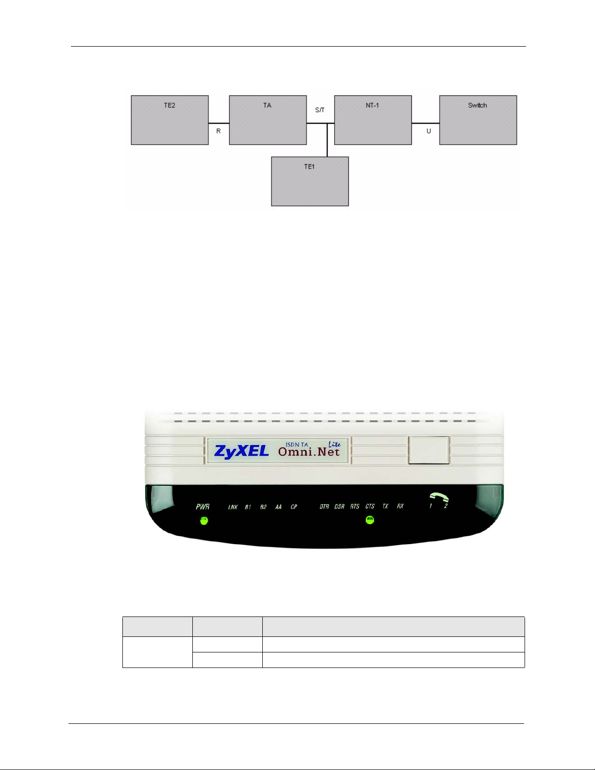
Figure 1 TA and ISDN Interfaces
Note: Do not connect this TA to a U interface.
1.2 TA Hardware and Driver Installation
Follow the instructions in the Quick Start Guide to install the driver and make hardware
connections.
Omni.Net Lite User’s Guide
1.3 Top Panel LEDs
Figure 2 Top Panel
The following table describes the LEDs on the top panel.
Table 1 Top Panel LED Description
LED STATUS DESCRIPTION
POWER On The TA is receiving power.
Off The TA is not receiving power.
Chapter 1 Introduction 20
Page 22

Omni.Net Lite User’s Guide
Table 1 Top Panel LED Description
LED STATUS DESCRIPTION
LNK On The TA has a successful connection to a local ISDN switch.
B1 On The ISDN B1 channel is in use.
B2 On The ISDN B2 channel is in use.
AA On The TA is in automatic answer mode.
CP On Data compression is not supported at the time of writing.
DTR (Data
Terminal
Ready)
DSR (Data Set
Ready)
RTS (Request
To Send)
CTS (Clear To
Send)
TX On The DTE is sending data to the TA.
RX On The DTE is receiving data from the TA.
PHONE 1
PHONE 2
Blinking The TA is attempting to make a local connection.
Off The TA is not connected to the local ISDN switch or the local
connection failed.
Off The ISDN B1 channel is idle or not established.
Off The ISDN B2 channel is idle or not established.
Blinking The TA is ringing.
Off The TA is not in automatic answer mode.
Data compression is being used over the B-channel(s).
Compression types are Hi/fn LZS (formerly Stac) for PPP
connections, and V.42bis for V.120 or X.75 connections.
Off Data compression is not activated.
On The DTE (Data Terminal Equipment) is your computer or terminal
that is connected to the TA TO DTE port. DTR indicates a DTE is
ready for communication by RS-232 signal.
Off The DTE is not ready for communication with the TA via a RS-232
link.
On The TA is ready for communication with the DTE.
Off The TA is not ready for communication with the DTE.
On The DTE is ready to receive data. The RTS signal is used in
hardware handshaking.
Off The DTE is not ready to receive data.
On The TA is ready to receive data.
Off The TA is not ready to receive data.
Off The DTE is not sending data to the TA.
Off The DTE is not receiving data from the TA.
On The telephone connected to this port is in use.
Off The telephone connected to this port is idle.
1.4 Configuration Methods
To configure your TA, choose one of the following methods:
• Utility
21 Chapter 1 Introduction
Page 23

Omni.Net Lite User’s Guide
• AT commands with a terminal emulation program such as Hyperterminal in Windows
• Tone commands using the telephone keypad (for analog ports)
Chapter 1 Introduction 22
Page 24

Omni.Net Lite User’s Guide
23 Chapter 1 Introduction
Page 25
CHAPTER 2
Using the Utility
This chapter shows you how to access and configure the TA using the utility.
2.1 Accessing the TA with the Utility
1 Make sure your TA hardware is properly connected (refer to the Quick Start Guide).
2 Insert the included CD into your CD-ROM driver.
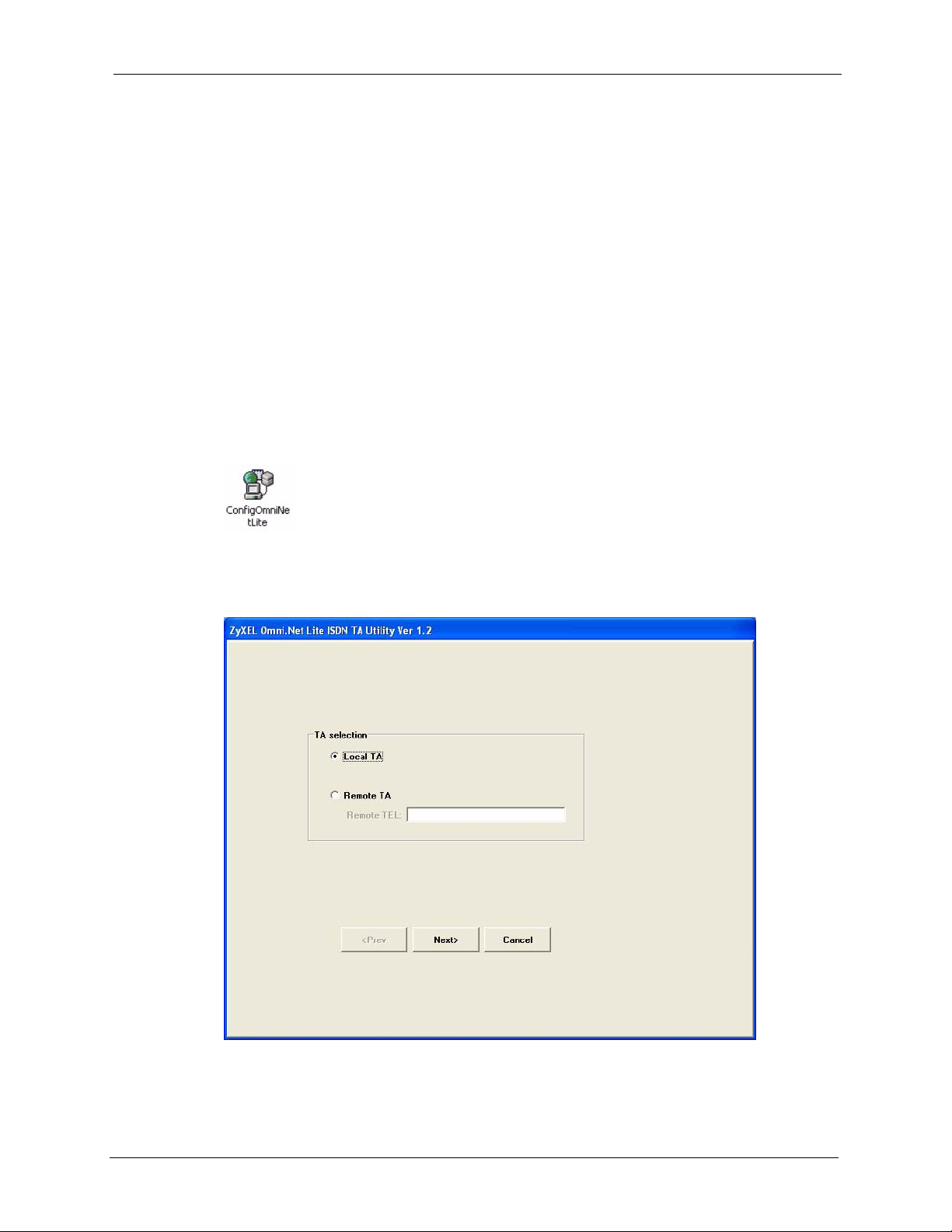
3 Double-click the ConfigOmniNetLite.exe icon, as shown below, in the Utility folder of
your CD.
Omni.Net Lite User’s Guide
4 You will see the screen as shown below. Select Local TA and click Next to access the
TA through the data port. Otherwise, select Remote TA, enter the phone number and
click Next to access the remote TA via an ISDN network.
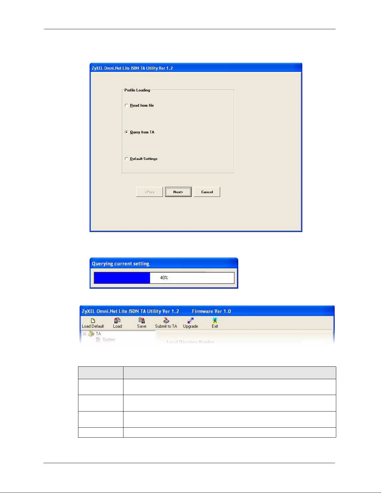
5 Select Query from TA and click Next to display the current settings on the TA. Select
Read from file and click Next to open a previously saved configuration file (.CFG) on
Chapter 2 Using the Utility 24
Page 26
Omni.Net Lite User’s Guide
your computer. Otherwise, select Default Settings and click Next to view the default
settings of the TA.
6 After you select Query from TA and click Next, the following screen appears while the
query is processing.
7 The utility main screen displays, you can see five icons on the navigation panel as shown.
Table 2 Navigation Panel
LABEL DESCRIPTION
Load Default Click this icon to clears all user-entered configuration information and returns the TA
to its factory defaults.
Load Click this icon to upload a new or previously saved configuration (.CFG) file from your
computer to your TA.
Save Click this icon to to back up (save) the TA’s current configuration to a file on your
computer.
Submit to TA Click this icon to save your changes back to the TA.
25 Chapter 2 Using the Utility
Page 27

Table 2 Navigation Panel
LABEL DESCRIPTION
Upgrade Click this icon to upload firmware to your TA.
Exit Click this icon at any time to leave the utility without saving.
2.2 Navigating the Utility
This section summarizes how to navigate the utility.
Figure 3 ZyXEL Utility Main Screen
Omni.Net Lite User’s Guide
The following table describes the menus listed on the left.
Table 3 Screens Summary
MENU SUB-MENU FUNCTION
System Use this screen to choose your country code.
RS232 Port Use these screens under this menu to configure the data
port.
Local DN and Call Type Use this screen to assign a phone number to data calls
and select call type.
Chapter 2 Using the Utility 26
Page 28

Omni.Net Lite User’s Guide
Table 3 Screens Summary
MENU SUB-MENU FUNCTION
Analog Port Use these screens under this menu to configure the
PPP/MP Parameters Use this screen to configure PPP/MP settings.
V.24 Signal Use this screen to define how to treat data control signal.
Incoming Call Screen Use this screen to set restrictions on incoming data calls.
Outgoing Call Screen Use this screen to set restrictions on outgoing data calls
Pre-stored Numbers Use this screen to store up to five phone numbers for
data calls on the TA.
Advance Setting Use this screen to configure the advanced settings,
including charge information.
analog ports.
Local DN and Options Use this screen to assign phone number(s) to voice calls,
set port priority, caller ID service types and dialing
method.
Incoming Call Screen Use this screen to set restrictions on incoming voice calls.
Outgoing Call Screen Use this screen to set restrictions on outgoing voice calls.
Pre-stored Numbers Use this screen to store up to five phone numbers for
voice calls on the TA.
Supplementary Service Use this screen to enable or disable the call waiting
feature.
2.3 System
Click System to display the screen as shown next. Select your country from the Country
Selection Code drop-down list. The default is Other.
27 Chapter 2 Using the Utility
Page 29

Figure 4 System
Omni.Net Lite User’s Guide
2.4 RS-232 Port: Local DN (Directory Number) and Call Type
This section shows you how to configure the data call number and type.
2.4.1 Introduction to PPP
Point-To-Point Protocol (PPP) is designed for simple one-to-one links. These links provide
full-duplex, simultaneous, bi-directional operation, and are assumed to deliver packets in
order. PPP is intended to provide a common solution for easy connection for a wide variety of
hosts, bridges and routers.
In the process of configuring, maintaining and terminating the point-to-point link, PPP goes
through several distinct phases, as specified in the following simplified state diagram:
Chapter 2 Using the Utility 28
Page 30

Omni.Net Lite User’s Guide
Figure 5 Point-to-Point Link Pathway
2.4.2 Multilink PPP (MP or MLP)
There are two B channels in basic rate ISDN. This offers the possibility of opening multiple
simultaneous channels between systems giving users additional bandwidth on demand.
Multilink PPP is a method for bundling both B-channels into one PPP link for higher
throughput.
Multilink PPP must be negotiated in the establish-link phase by both peers. If the negotiation
is successful, the second link will be dialed after the first link reaches network phase. In some
countries the directory number is not the same for both channels. For dialing the second Bchannel with a different directory number, both numbers must be obtained before dialing out
unless the peer supports BACP and BAP, which will be described later in this chapter.
Multilink PPP is described in RFC-1990.
2.4.3 BACP and BAP
Bandwidth Allocation Control Protocol (BACP) and Bandwidth Allocation Protocol (BAP) is
used for call request and link drop under Multilink PPP.
BACP is negotiated during the network phase. Without BACP/BAP, the directory numbers of
both B-channels must be specified before dialing out. In some cases, it is not possible for the
ISP to support more than one chassis that is capable of bundling both channels at the same
time. With BACP/BAP, the second B-channel directory number can be obtained while
requesting a call. The second directory number is not necessary any more.
29 Chapter 2 Using the Utility
Page 31

2.4.4 ISDN Protocols
HDLC (High-Level Data Link Control) is one of the most common data link (layer 2)
protocols. It supports both half duplex and full duplex communication lines, point to point
(peer to peer) and multi-point networks, and switched or non-switched channels. It permits
synchronous, code-transparent data transmission.
The TA supports the following protocols.
Table 4 ISDN B-channel Protocols
Omni.Net Lite User’s Guide
ISDN
PROTOCOLS
V.110 V.110 is most popular in Japan or Europe.
V.120 V.120 is most commonly used in North America.
X.75 X.75 was originally designed for packet-switched signaling systems in public
PPP and MLP PPP allows B-channels bundling and bandwidth release and is the most widely
DESCRIPTION
networks to provide data transmission services. However, it is now also used as
the link layer for telematic services (as defined in T.90) in ISDN. These services
include both ISDN circuit-switched mode (DTE-DTE communication) and ISDN
packet-switched mode (DTE-DCE communication). DCE (Data Communication
Equipment) is a device, such as a modem, that converts data between different
interfaces (digital and analog for example) and exchanges data with the DTE.
used protocol for Internet access.
2.4.5 Configuring Local DN and Call Type
Click Local DN and Call Type under RS-232 Port to open the screen as shown next.
Chapter 2 Using the Utility 30
Page 32

Omni.Net Lite User’s Guide
Figure 6 RS-232 Port: Local DN and Call Type
The following table describes the labels in this screen.
Table 5 RS-232 Port: Local DN and Call Type
LABEL DESCRIPTION
Local Directory Number
Address Enter the phone number of the data port.
SubAddress Enter the sub-address of the data port.
CLIP and CLIR
Selection
CLIP (Calling Line Identity Presentation) displays the phone number of the
caller on the callee’s telephone. CLIR (Calling Line Identity Restriction) allows
you to hide your phone number when you make a call.
Select CLIP (pass self DN to destination site) to allow the ISDN switch to
pass your phone number to the destination site.
Select CLIR (don’t pass self DN to destination site) to disable the CLIP
service.
31 Chapter 2 Using the Utility
Page 33

Omni.Net Lite User’s Guide
Table 5 RS-232 Port: Local DN and Call Type
LABEL DESCRIPTION
Call Type Sets the calling protocol for the your TA. The protocol selected should match
the protocol in use by the device or network your ISDN TA is calling.
Select HDLC transparent to apply HDLC on B-channels and allow peer to
peer communication similar to what a modem does.
Select X.75 or V.120 to do CRC (Cyclic Redundancy Check) error detecting
on B-channel. X.75 performs error correction using LAPB (Link Access
Procedure Balanced) and V.120 uses LAPD (Link Access Procedure on the D
Channel).
Select PPP or MLP for modem-like dial-up connection to the Internet and/or
combining two B-channels into one.
Select V.11 0 to allow rate adaption between sync 64 kbps B-channel and
async 9.6 - 115.2 kbps DTE.
X.75 Setup
Transmitting Frame
Size (bytes)
Select a value between 128 and 2048 to change the sending frame size.
The default sending frame size is 254 bytes.
2.5 RS-232 Port: PPP/MP Parameters
This section shows you how to configure PPP or MP parameters.
2.5.1 Link Authentication
After a link is established, it is necessary to authenticate the peer for security reasons. There
are two popular authentication methods. One is Password Authentication Protocol (PAP) and
the other is Challenge Handshake Authentication Protocol (CHAP). PAP is less secure
because it transmits the username/password in plain text form. Unlike PAP, CHAP transmits
the username/password in encrypted form. Some ISPs may support CHAP as the only method
for authentication.
2.5.1.1 Windows Authentication
For those applications that do not support CHAP, the TA converts CHAP into PAP. It is
recommended that you select Allow unsecured password in the Dial-up Connection
Property Security screen on Windows 2000/XP or do not select the Required encrypted
password checkbox in the Dial-up Connection Property Server Types screen on
Windows 95/98 by right-clicking on the dial-up connection icon (see the figures below), since
Microsoft uses MS-CHAP for username and password encryption but MS-CHAP is not
supported by most ISPs.
Chapter 2 Using the Utility 32
Page 34

Omni.Net Lite User’s Guide
Figure 7 Windows XP: Dial-up Connection: Property
Figure 8 Windows XP: Dial-up Connection Property: Security
33 Chapter 2 Using the Utility
Page 35

Figure 9 Windows 98: Dial-up Connection Property: Server Types
Omni.Net Lite User’s Guide
If you choose MLP 128K (dynamic or fixed) in the utility (see Figure 10 on page 35) or using
the ATC0=8CI=1 command, the TA needs the username and password in plain text form to
establish the connection. Do not select Enable CHAP in the PPP/MP Parameters screen.
CHAP is described in RFC-1994 and PAP is described in RFC-1334.
2.5.2 Call Bumping (Bandwidth Release) for Voice Calls
While dynamic Multilink PPP is active and you place or answer a voice call from a device that
is attached to one of the PHONE ports, the TA automatically drops one of the channels and
assigns it to voice calls. If you subscribe to the call waiting service from your local telephone
company, the TA will also drop one of the channels and answer the incoming call. Once a
voice call ends, the TA automatically re-establishes the channel depending on the BOD rule.
2.5.3 Bandwidth On Demand (BOD)
In multilink PPP mode, use BOD to bring up or drop a B-channel depending on current data
traffic. If there is light traffic on the link, one of the channels will be dropped automatically.
On the other hand, if only one B-channel is used and data traffic is high enough, BOD will
bring up the second B-channel to increase the bandwidth of the data link.
The BOD function is only effective on your TA.
For BOD, there are three parameters to set high/low threshold and persist time. Traffic
utilization is measured in the ISDN link. Highly compressible data may not generate enough
traffic to start the second B-channel. Both add-persist time and subtract-persist time must be
set to activate BOD.
Chapter 2 Using the Utility 34
Page 36

Omni.Net Lite User’s Guide
Note: The high threshold must be greater than the low threshold, otherwise, both of
them will be reset to the default.
2.5.4 Configuring PPP/MP Parameters
Click PPP/MP Parameters under RS-232 Port to display the screen as shown next.
Figure 10 RS-232 Port: PPP/MP Parameters
The following table describes the labels in this screen.
Table 6 RS-232 Port: PPP/MP Parameters
LABEL DESCRIPTION
Enable Fixed MP
(fixed 128K)
Enable CHAP Select this option to have your TA use CHAP for link authentication with the
Enable Call Bumping Select this option to allow bandwidth release for voice calls.
Maximum throughput
(1 or 2 B-channel)
35 Chapter 2 Using the Utility
Select this option to combine both B-channels into one PPP link for data calls
and always has the higher transmission rate.
username and/or password.
This field is not available if you select Enable Fixed MP.
Select 64 kbps (1 B-channel) to activate only one B-channel and transmit
data at 64 kbps.
Select 128 kbps (2 B-channel) if if you want to bundle two B-channels to
increase the data transfer rate. This is called multilink.
Page 37

Table 6 RS-232 Port: PPP/MP Parameters
LABEL DESCRIPTION
Omni.Net Lite User’s Guide
Threshold of data
loading to ADD/DROP
one channel
Persist time for
monitoring threshold to
add or drop one
channel
This field is not available if you select Enable Fixed MP.
Set the maximum threshold in the ADD field and the minimum threshold in the
DROP field. The TA adds the second B-channel when traffic is above the
threshold and drops the second B-channel when traffic is below the threshold.
This field is not available if you select Enable Fixed MP.
Set the time interval between calculating traffic load. The unit of a value is 5
seconds.
2.6 RS-232 Port: V.24 Signal
The V.24 signal screen describes ways to treat data control signal for data transmitted via the
RS-232 serial interface of the TA. You can also use this screen to configure how to control
data flow between the computer and the TA.
2.6.1 RS-232 Flow Control
RS-232 Flow control is used to control data flow between devices, such as two modems or a
computer and a modem, using a serial connection. Standard flow control protocols include
hardware (RTS/CTS) flow control and software (XON/XOFF) flow control.
The RTS (Request To Send) and CTS (Clear to Send) lines of a RS-232 serial cable signal
flow control handshaking. In the following example, A is a TA and B is a computer. For
upstream traffic from B to A, when device A’s receive buffer is nearly full, it lowers the CTS
line (the CTS LED is off) to signal device B to stop sending data. When A is ready for new
incoming data, it raises the CTS signal (the CTS LED is on) to resume transmissiom. For
downstream traffic from A to B, B sets the RTS line to have A stop or restart sending data.
Figure 11 CTS/RTS Handshake
Flow control can also be done using the XON character (by pressing Ctrl-Q on the keyboard)
and XOFF characters (by pressing Ctrl-S) in a data stream. When a device receives an XOFF
signal from another device, it suspends or stops data transmitting to that device until receiving
an XON (Ctrl-Q) signal from the same device. An XOFF character is sent when the receive
buffer is nearly full. An XON signal is sent when the buffer is no longer full. Binary files may
contain these signal characters and cannot be sent with XON/XOFF flow control protocol.
Chapter 2 Using the Utility 36
Page 38

Omni.Net Lite User’s Guide
Note: The TA and the computer should use the same flow control protocol.
2.6.2 Configuring V.24 Signal
Click V.24 Signal under RS-232 Port to display the screen as shown next.
Figure 12 RS-232 Port: V.24 Signal
37 Chapter 2 Using the Utility
Page 39

The following table describes the labels in this screen.
Table 7 RS-232 Port: V.24 Signal
LABEL DESCRIPTION
Omni.Net Lite User’s Guide
Data Carrier Detect
Control
Data Terminal Ready
Action
Flow Control Setting Select the flow control method from the drop-down list. Options are Disable
Data Set Ready DSR indicates whether or not the TA is ready for data transmission.
Data Carrier Detect (DCD) is a serial communication signal. It indicates
whether or not the TA is connected to a remote modem.
Select Follow DTR signal to raise the DCD signal and have the LED turn on
when the DTR signal is raised and the DTR LED is on and vice versa.
Select On only if in communication to raise the DCD signal and have the
LED turn on only when a data call is established.
DTR indicates whether or not the computer or terminal is ready for data
transmission.
Select ON to OFF, disconnect the call (108/2) to have the computer or
terminal disconnect the current data call if the DTR signal is lowered and the
LED is off.
Select Ignore DTR status so that the TA will not follow the behavior of the
DTR signal to drop a call; you then need to use the ATH command to
disconnect it.
Select OFF to ON, make a call, On to OFF, clear the call (108/1) to have the
TA dial out a call using the pre-stored phone number when the DTR LED turns
on and disconnect the call when it is off.
flow control, CTS/RTS flow control and XON/XOFF flow control.
Select Follow DTR signal to have the DSR LED turn on when the DTR LED is
on and vice versa.
Select Follow DCD signal to to have the DSR LED turn on when the DCD
LED is on and vice versa.
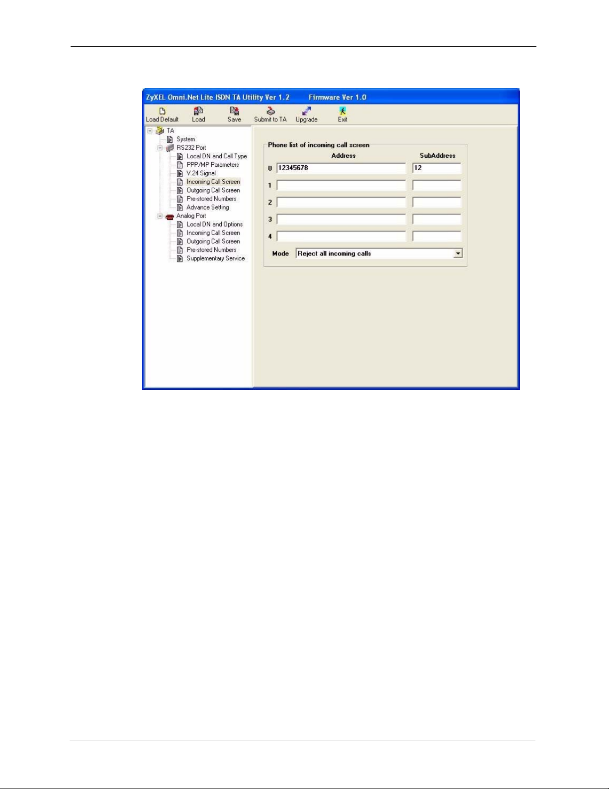
2.7 Incoming Call Screening
Use this function to set restrictions on incoming data or voice calls.
In Incoming Call Screen under RS-232 Port or Analog Port, create a list of incoming call
phone numbers (with sub-addresses) and configure the Mode field to reject or accept the calls
with the phone number in the list.
Chapter 2 Using the Utility 38
Page 40
Omni.Net Lite User’s Guide
Figure 13 RS-232 Port: Incoming Call Screen
2.8 Outgoing Call Screening
Use this function to set restrictions on outgoing data or voice calls, such as allowing or
prohibiting a long-distance or international call.
In Outgoing Call Screen under RS-232 Port or Analog Port, create a list of prefix digits for
outgoing call and configure the Mode field to prohibit or allow the calls with the prefix digits
in the list.
39 Chapter 2 Using the Utility
Page 41

Figure 14 Analog Port: Outgoing Call Screen
Omni.Net Lite User’s Guide
2.9 Pre-stored Numbers
To store a phone number for data calls or voice calls in the TA, click Pre-stored Numbers
under RS-232 Port or Analog Port and enter the phone numbers (and sub-addresses) in the
screen shown as below.
Chapter 2 Using the Utility 40
Page 42

Omni.Net Lite User’s Guide
Figure 15 Analog Port: Pre-stored Numbers
2.10 RS-232 Port: Advance Setting
Use this screen to configure data port settings and charge information.
Click Advance Setting under RS-232 Port to display the screen as shown next.
41 Chapter 2 Using the Utility
Page 43

Figure 16 RS-232 Port: Advance Setting
Omni.Net Lite User’s Guide
The following table describes the labels in this screen.
Table 8 RS-232 Port: Advance Setting
LABEL DESCRIPTION
Advance Options
Auto Answer Set how many ringing messages the TA receives before it answers a data call
automatically.
Enter 0 to stop the TA answering a data call automatically. When there is an
incoming data call, you can press the push button on the top panel (see the
Quick Start Guide) or use the
Wait for Conn Enter the number of seconds for the TA to wait for an answer to the data call
before dropping it.
Power on baud rate Configure the initial baud rate after power-on.
Power on attribute Configure the initial attribute of the data port after power-on.
Extended result code Select extended result code to show the extended command response or the
connect message to the DTE (see Table 20 on page 66). Otherwise, select
basic result code (default).
Ring result code Select the information you want to display for the incoming calls. Options are
no extended information (default), display calling phone number, display
user data, display calling phone number and user data and RVS-COM
format.
Charge Information
ATA command to answer it manually.
Chapter 2 Using the Utility 42
Page 44

Omni.Net Lite User’s Guide
Table 8 RS-232 Port: Advance Setting
LABEL DESCRIPTION
Last call charge info. This field displays the cost for the last call. This feature is not supported by all
ISDN switches.
Clear last call charge
info.
Accumulate Charge
Info.
Clear accumulate
charge info.
Power On Auto-Dialing Select 1 to have the TA automatically dial up a connection after power-on.
Maximum Retry Count
to Redial
Select this checkbox to clear the information in the field above.
This field displays total cost for all calls. This feature is not supported by all
ISDN switches.
Select this checkbox to clear the information in the field above.
Select 0 to disable this feature.
Enter how many times (from 1 to 10) for the TA to try to dial out a data call if a
call can not be established successfully.
Enter 0 to disable this feature.
2.11 Analog Port: Local DN and Options
This section shows you how to assign the phone number(s) to voice calls and set port priority.
2.11.1 MSN (Multiple Subscriber Number) and Subaddress
Multiple Subscriber Number (MSN) is where the telephone company gives you more than one
number for your ISDN line. You can assign each number to a different port, e.g., the first
number to data calls, the second to A/B adapter 1 and so on. Or (DSS1) the telephone
company may give you only one number, but allow you to assign your own subaddresses to
different ports, e.g., subaddress 1 to data calls and 2 to A/B adapter 1.
2.11.1.1 Phone Number Assignment Example
Different telephone companies deploy different types of switches for ISDN service.
Depending on the switch for your particular installation, you will have a different number of
telephone numbers.
When your telephone company provides you with more than one phone number (say 5009001
and 5009002), you can connect two analog phones and/or G3 fax devices to the PHONE 1 and
PHONE 2 ports and assign each number to a port. If you attach one analog phone and one fax
machine to the analog ports but don’t assign any phone number to either port, both telephone
and fax ring when there is an incoming call. That will be difficult to tell whether it is a fax call
or voice call.
Follow the steps for the configuration method of your choice to assign the phone numbers.
After configuration, the TA will route a call to the port that matches the dialed number.
1 Refer to Section 2.1 on page 24 to open the utility.
43 Chapter 2 Using the Utility
Page 45

2 Enter the first number in the Address field beside Port 1 and the second number in the
Address field beside Port 2.
3 Click Submit to TA to save the changes back to the TA.
2.11.2 Caller ID
The caller ID (Caller Identification) information will display on the analog ports. Two caller
ID service types are supported by your TA.
2.11.2.1 Type 1: On-hook Caller ID Transmission
If the caller ID protocol uses DTMF (Dual Tone Multi-Frequency) signal, the caller ID
information includes the phone number and is sent prior to ringing.
If the caller ID protocol uses FSK (Frequency Shift Keying) signal, the phone number will be
sent during ringing.
The caller ID signaling type varies depending on the country.
Omni.Net Lite User’s Guide
Table 9 Caller ID signaling type
COUNTRY COUNTRY CODE CALLER ID SIGNALING TYPE RINGING PATTERN
Denmark 252 DTMF 1 Sec On, 2 Sec OFF
France 219 FSK 1 Sec On, 2 Sec OFF
German 237 FSK 1 Sec On, 2 Sec OFF
India 214 DTMF 1 Sec On, 2 Sec OFF
Ireland 235 FSK 0.4 Sec On, 0.2 Sec OFF,
0.4 Sec On, 2 Sec OFF
Italy 236 DTMF 1 Sec On, 2 Sec OFF
Netherland 253 DTMF 1 Sec On, 2 Sec OFF
Norway 245 FSK 1 Sec On, 2 Sec OFF
Portugal 220 DTMF 1 Sec On, 2 Sec OFF
Spain 213 DTMF 1 Sec On, 2 Sec OFF
Sweden 250 DTMF 1 Sec On, 2 Sec OFF
Switzerland 251 DTMF 1 Sec On, 2 Sec OFF
UK 249 FSK 0.4 Sec On, 0.2 Sec OFF,
0.4 Sec On, 2 Sec OFF
Other (default) 216 DTMF 1 Sec On, 2 Sec OFF
2.11.2.2 Type 2: Off-hook Caller ID Transmission
The Type 2 service uses only FSK and shows call waiting caller ID. If the service is supported
and activated on your TA, the call waiting phone number is displayed when you are on the
phone.
Chapter 2 Using the Utility 44
Page 46

Omni.Net Lite User’s Guide
2.11.3 Dialing Method
There are two ways to send a message containing the phone number: EN-BLOC sending and
OVERLAP sending.
In En-Bloc mode, the complete phone number is sent in the first signaling message. Users
enter all digits of the phone number before a timeout period expires (the call times out if there
is inactivity for more than four seconds) or press “#” to indicate the complete phone number
has been entered.
OVERLAP sending is similar to what the traditional PSTN (Public-Switched Telephone
Network) telephone system uses. OVERLAP sending means sending some phone digits in
the first signaling message and the rest in subsequent signaling message. Users enter the phone
number after a dial tone. The ISDN network is aware of the completion of the phone number
automatically. You can not enter the sub-address when using overlap sending.
OVERLAP sending is usually used as the default for voice calls. For data calls, only ENBLOC sending is used.
2.11.4 Configuring Local DN and Options
Click Local DN and Options under Analog Port to display the screen as shown next.
Figure 17 Analog Port: Local DN and Options
45 Chapter 2 Using the Utility
Page 47

Omni.Net Lite User’s Guide
The following table describes the labels in this screen.
Table 10 Analog Port: Local DN and Options
LABEL DESCRIPTION
Local Directory Number
Port 1
Port 2
CLIP and CLIR
Selection
Device type on analog
port
Port Priority To set the same priority for both two ports, select Port priority to Both ports
Dialing method Configure how to send the signaling message with the phone number. Options
Enter the ISDN phone number for voice calls in the Address field and the subaddress in the SubAddress field.
CLIP (Calling Line Identity Presentation) displays the phone number of the
caller on the callee’s telephone. CLIR (Calling Line Identity Restriction) allows
the phone number to be hid.
Select CLIP (pass self DN to destination site) to allow the ISDN switch to
pass your phone number to the destination site.
Select CLIR (don’t pass self DN to destination site) and the CLIP service
will not be available.
To enable the Type 2 service on either analog port, select Telephone with
Call Waiting caller ID device.
Otherwise, select Telephone, G3 Fax or Modem.
are same priority.
To set the PHONE 1 port to have the first priority, select Port priority to
Analog Port 1 is high priority.
To set the PHONE 2 port to have the first priority, select Port priority to
Analog Port 2 is high priority.
are OVERLAP sending and EN-BLOC sending.
2.12 Voice Calls
This section covers how to initiate and receive calls over an ISDN through the analog ports on
your ISDN TA and introduces supplementary services including call hold, call waiting, call
transfer and three-way conference.
Note: You can only use the utility, AT command or Tone command to activate or
deactivate call waiting. Use the flash key and the digit keys on the telephone to
invoke supplementary services (see Section 2.12.4 on page 47).
2.12.1 Placing a Voice Call
You can use your analog phone connected to the PHONE 1 and PHONE 2 ports to dial out a
call directly. With the Quick Dial feature, you can place an ISDN voice call by dialing “nn#”
(where nn=00-04, pre-stored phone number index). You must store up to five phone numbers
first by using the utility, AT commands or tone commands. Refer to Section 2.9 on page 40 on
how to store a phone number with the utility.
Chapter 2 Using the Utility 46
Page 48

Omni.Net Lite User’s Guide
2.12.2 Answering a Voice Call
To answer an incoming call, just pick the receiver when that telephone is ringing.
Voice calls are routed to one or both of the analog ports (PHONE 1 or/and PHONE 2) based
on the phone number assignment when they are received. When the same number is assigned
to both ports, you can choose the port you want to receive calls by setting the priority of the
ports. If two ports have same priority, both ports receive ring signals. See Section 2.11.4 on
page 45 on how to configure port priority.
When answering an incoming call, the TA will first be identified if the calling number matches
the MSN settings. The Multiple Subscriber Number (MSN) supplementary service enables
multiple ISDN numbers to be assigned to a single ISDN BRI line. It allows the caller to select,
via the public network, one or more distinct terminals from a variety of terminal choices. Since
the TA supports many different communication protocols and two analog adapters, each of
these ports can individually be assigned to a different ISDN number (see Section 2.11.1 on
page 43 for more information).
The following table shows incoming voice call scenarios.
Table 11 Incoming Voice Call Scenarios
PHONE 1 MSN PHONE 2 MSN PORT PRIORITY PHONE 1 PHONE 2
Unassigned or
Matched
Unassigned or
Matched
Unassigned or
Matched
Matched Not matched None Ring -
Not matched Matched None - Ring
Not matched Not matched None - -
2.12.3 Intercom
Your TA can work as an “Intercom” by connecting two phones to PHONE 1 and PHONE 2
at the rear panel of your TA.
Please follow the instructions below to operate the Intercom:
1 Pick up the telephone handset.
Unassigned or
Matched
Unassigned or
Matched
Unassigned or
Matched
0 Ring Ring
1Ring-
2 - Ring
2 Dial “1#” and the other local phone will start to ring.
2.12.4 Supplementary Services
Supplementary services such as call hold, call waiting, call transfer, … are generally available
from your telecommunications provider. The TA supports all of the following services:
47 Chapter 2 Using the Utility
Page 49

• Call Hold
• Call Waiting
• Call transfer
• Three-Way Conference
Note: To take full advantage of the supplementary voice services available though
the TA's phone ports, you will need to subscribe to the services from your local
telephone company.
2.12.4.1 The Flash Key
Flashing means to press the hook for a short period of time (a few hundred milliseconds)
before releasing it. On newer telephones, there should be a "flash" key (button) that generates
the signal electronically. If the flash key is not available, you can tap (press and immediately
release) the hook by hand to achieve the same effect. However, using the flash key is
preferred since the timing is much more precise. With manually tapping, if the duration is too
long, it may be interpreted as hanging up by the TA.
You can invoke all the supplementary services by using the flash key. Commands for
supplementary services are listed in the table below
Omni.Net Lite User’s Guide
After pressing the flash key, if you do not issue the sub-command before the default subcommand timeout (2 seconds) expires or issue an invalid sub-command, the current operation
will be aborted.
Table 12 Flash Key commands
COMMAND SUB-COMMAND DESCRIPTION
Flash Put a current call on hold to place a second call.
Flash 0 Drop the call presently on hold or reject an incoming call which is
Flash 1 Disconnect the current phone connection and answer the incoming
Flash 2 1. Switch back and forth between the two calls.
Flash 3 Create three-way conference connection.
Flash 4 Transfer the call to another phone.
2.12.4.2 Call Hold
Call hold allows you to put a call (A) on hold by pressing the flash key.
waiting for answer.
call or resume with caller presently on hold.
2. Put a current call on hold to answer an incoming call.
3. Separate the current three-way conference call into two
individual calls (one is on-line, the other is on hold).
If you have another call, press the flash key and then “2” to switch back and forth between
caller A and B by putting either one on hold.
Chapter 2 Using the Utility 48
Page 50

Omni.Net Lite User’s Guide
Press the flash key and then “0” to disconnect the call presently on hold and keep the current
call on line.
Press the flash key and then “1” to disconnect the current call and resume the hold call.
If you hang up the phone but a caller is still on hold, there will be a remind ring (see Section
4.1.1 on page 68 for more information).
2.12.4.3 Call Waiting
This allows you to place a call on hold while you answer another incoming call on the same
telephone (directory) number. By default call waiting is enabled on both telephone ports, but
can be disabled on either port.
If there is a second call to a telephone number, you will hear a call waiting tone. Take one of
the following actions.
• Reject the second call.
Press the flash key, wait for the sub command tone, press “0”.
• Disconnect the first call and answer the second call.
Either press the flash key, wait for the sub command tone and press “1”, or just hang up
the phone and then answer the phone after it rings.
• Put the first call on hold and answer the second call.
Press the flash key, wait for the sub command tone, press “2”.
2.12.4.3.1 Disabling Call Waiting
The call waiting tone will interfere with the data communication. It is highly recommended
that you disable the call waiting feature on the port to which a fax or modem is connected.
To disable call waiting on either port, select the Disable PORT 1/2 call waiting check box
in the Analog Port Supplementary Services screen of the utility.
49 Chapter 2 Using the Utility
Page 51

Figure 18 Analog Port: Supplementary Service
Omni.Net Lite User’s Guide
2.12.4.4 Call Transfer
You can transfer a call to a local phone (connected to the TA) or a remote phone (not
connected to the TA) through an ISDN line.
2.12.4.4.1 Call Transfer between Two Analog Ports
To transfer incoming calls (after you answer this call) to a local phone, follow these steps:
1 Press the flash key to put the caller on hold.
2 When you hear the dial tone, dial “1#” to operate the Intercom.
3 After you hear the ring signal or the second party answer it, press the flash key, then “4”.
4 Hang up the phone.
2.12.4.4.2 Call Transfer to a Remote Phone
To transfer incoming calls (after you answer this call) to a remote phone, follow these steps:
1 Press the flash key to put the caller on hold.
2 When you hear the dial tone, simply dial the number you want, to transfer the first call.
3 After you hear the ring signal or the second party answer it, press the flash key, then “4”.
Chapter 2 Using the Utility 50
Page 52

Omni.Net Lite User’s Guide
4 Hang up the phone.
2.12.4.5 Three-Way Conference
1 When you are on the phone talking to someone, place the flash key to put the caller on
hold and get a dial tone.
2 Dial a phone number directly to make another call.
3 When the second call is answered, press the flash key, wait for the sub-command tone
and press “3” to create a three-way conversation.
4 Hang up the phone to drop the connection.
5 If you want to separate the activated three-way conference into two individual
connections (one is on-line, the other is on hold), press the flash key, wait for the subcommand tone and press “2”.
51 Chapter 2 Using the Utility
Page 53

Using AT Commands
3.1 AT Commands Overview
An AT Command is a command in asynchronous data format issued by the computer to the
ISDN TA through the asynchronous computer-modem interface. AT commands are used to
configure and control the TA by typing commands at a computer or terminal keyboard. To
send an AT Command from a computer to the TA, you must run a communication software
program and the TA must be in command state.
Commands must be written in a specific form in order for the TA to recognize them. A
command begins with the letters “AT” or “at”, followed by one or more printable characters
and then ended by pressing [ENTER], as shown in the following example.
Omni.Net Lite User’s Guide
CHAPTER 3
Table 13 Examples of AT Command
COMMAND OPERATION RESPONSE
AT<Enter> To verify that the TA is online with your terminal or computer. OK
AT I3 To display the version of the current firmware.
Note: AT commands can only be issued when the computer or terminal is connected
to the TA with an RS-232 cable.
3.2 Accessing the TA Example
To configure the TA by terminal emulation program, you need a terminal emulation program
first, such as Hyperterminal in Windows.
1 Make sure your TA hardware is properly connected (refer to the Quick Start Guide).
2 Open the HyperTerminal program in Windows. For example, in Windows XP click
Start, Programs, Accessories, Communications, HyperTerminal.
Chapter 3 Using AT Commands 52
Page 54

Omni.Net Lite User’s Guide
3 Enter a descriptive name and select an icon in the Connection Description screen. Click
OK to display the Connect To screen.
4 Select the COM port to which the TA is connected. Click OK to continue.
5 In the COM Properties screen, click OK after configuring the following parameters:
• VT100 terminal emulation
• Baud rate between 9600 and 230400 bps, the default is 115200 bps.
53 Chapter 3 Using AT Commands
Page 55

Omni.Net Lite User’s Guide
• No parity, 8 data bits, 1 stop bit, flow control set to hardware
6 The DTR LED is on. If it is off, check the HyperTerminal settings and your cable
connections.
7 Type in AT and press
[ENTER]. The terminal will response OK as shown below. You can
now use the commands with an “AT” or “at” prefix to configure the TA. Refer to Chapter
5 on page 72 for detailed information on AT command sets.
Chapter 3 Using AT Commands 54
Page 56

Omni.Net Lite User’s Guide
3.3 AT Commands
The following tables summarize the AT command sets.
3.3.1 Data Command Sets
The AT data command sets are shown in the following table.
Table 14 AT Data Command Sets Requiring an "AT" Prefix
COMMAND OPTION DESCRIPTION
A Answer an incoming call.
C0=n Select the call type.
C1=n This feature is only available when you select PPP or MLP call
D <phone number>
[/<sub-address>]
[:<user data>]
n=1:HDLC transparent
n=3: V.110
n=4: V.120
n=5: X.75
n=8: PPP or MLP (default).
type (C0=8).
Configure maximum throughput by using one B channel or two B
channels.
n=0: 64 Kbps (one B channel)
n=1: 128 Kbps (two B channels)
Dial an outgoing call.
<phone number>: Enter up to 32 characters, including digits
from 0 to 9, *, #, hyphen ( -), comma (,) and (‘,’). [‘,’] will be
ignored.
<sub-address>: Enter up to 20 ASCII characters ranging from
“0-9”,” a-z” and “A-Z”.
<user data>: Enter up to 128 printable characters.
Note: ATDT, ATDP and ATDW are all same as ATD.
DS=n[:<user data>] Dial an outgoing call using a pre-stored phone number.
n: pre-stored phone number index
<user data>: Enter up to 128 printable characters.
DL Dial the last-dialed number, including the user data.
E Enable or disable the command echo function.
E0 Disable the command echo function.
E1 Enable the command echo function (default).
H Hang up a call.
I Display product information.
I2 Display the model name.
I3 Display the firmware version.
I4 Display the hardware version.
I11 Display the bootcode version.
55 Chapter 3 Using AT Commands
Page 57

Omni.Net Lite User’s Guide
Table 14 AT Data Command Sets Requiring an "AT" Prefix
COMMAND OPTION DESCRIPTION
O Change from escape mode to data mode.
+++ is the escape sequence code that is entered in data state to
return the ISDN TA to command state. The TA will accept AT
commands only while it is in command state.
Q Enable or disable result code.
Q0 Enable result code (default).
Q1 Disable result code.
S0=n n=0: DIsable the auto answer feature.
n=1-255: Enable the auto answer feature to answer a call after it
rings for n times.
S1 Display read-only last ringing counting for the current incoming
call.
S2=n Set the monitored 3 continuous characters (ESC-Sequence) to
enter command mode.
n=0~127, the default is 43, that is "+++".
S3=n Set the character value as CR.
n=0~127, the default is 13.
S4=n Set the character value as LF.
n=0~127, the default is 10.
S5=n Set the character value as BS (Backspace).
n=0~127, the default is 8.
S7=n The time (in seconds) you wait before connection.
n=1-255, the default is 60.
S12=n Set the "Guard time" for "ESC-Sequence" ( in company with
S25=n The DTR transition time. The unit is 0.05 second.
S50=n Forwarding character in data mode.
S51=n Set how much time the TA is left idle in data mode. The unit is
S80 Display the read-only cause value of disconnection in the last
V Select result code format.
V0 Display result code in numeric form.
V1 Display result code in verbose form (default).
W Display extended information of "RING" result code.
W0 No extended information.
W1 Display phone number of calling site.
"+++" ). The unit is 0.1 second.
n=0: ignore "Guard time".
n=1-255, the default is 10.
n=1-255, the default is 1.
n=0: no forwarding character (default)
n=2: select CR as forwarding character
0.01 second.
n=1-255, the default is 2.
call.
Chapter 3 Using AT Commands 56
Page 58

Omni.Net Lite User’s Guide
Table 14 AT Data Command Sets Requiring an "AT" Prefix
COMMAND OPTION DESCRIPTION
X Enable/Disable extended result code.
Z Reload user-defined profile.
&C DCD signal control.
&D DTR (Data Terminal Ready) signal control.
&F Restore the factory default.
&K Set flow control mode.
&S DSR (Data Set Ready) signal control.
&V Display all data parameters settings.
&W Save current parameters setting, include &-leading and non-
%D0=n Select DTE baud rate when system is powered on.
%D1=n Select DTE attribute when system is powered on.
%D2=n Dial an outgoing data call automatically if there is pre-stored
W2 Display user data.
W3 Display phone number of calling site and user data.
X0 Basic result code (default).
X1 Extended result code.
&C0 Follow DTR signal.
&C1 ON only if in communication (default).
&D0 Ignore DTR signal, assume DTR is always ON.
&D1 DTR OFF-ON transition causes dial of an outgoing call using the
first pre-stored phone number.
&D2 DTR OFF causes the modem to hang up (default).
&K0 Disable flow control.
&K3 Enable CTS/RTS flow control (default).
&K4 Enable XON/XOFF flow control.
&S0 Follow DTR signal (default).
&S1 Follow DCD signal.
leading parameters, as user defined profile.
n=8: 9600 bps
n=11: 19200 bps
n=13: 38400 bps
n=16: 57600 bps
n=17: 115200 bps (default)
n=21: 230400 bps
n=0: 8 data bits, non parity (default)
n=1: 7 data bits, even parity
n=2: 7 data bits, odd parity
dialing number after system is powered on.
n=0: do nothing (default)
n=1: auto-dial after power on
57 Chapter 3 Using AT Commands
Page 59

Omni.Net Lite User’s Guide
Table 14 AT Data Command Sets Requiring an "AT" Prefix
COMMAND OPTION DESCRIPTION
%D3=n The number of retrying to re-dial the outgoing data call once TA
failed to establish the data call.
n=0: don't re-dial.
n=1~10: re-dial for n times until the call is established.
%Id=<phone
number> [/<subaddress>]
%M1=n Enable/Disable PAP to CHAP conversion.
%M2=n Enable/Disable "Dynamic Bandwidth Allocation for Voice Call".
%M3=n Set threshold of data loading to add one channel, the unit is
%M4=n Set a threshold of data loading to drop one channel, the unit is
%M5=n Persist time for monitoring threshold to add or drop one channel,
%Od=<prefix digits> Create a list of the outgoing call prefix digits for the data port.
%P0=n Set incoming call screen mode for the data port.
%P1=n Set outgoing call screen mode for the data port.
Create a list of the incoming call phone number via the data port.
d=0-4.
<phone number>: Enter up to 32 characters, including digits
from 0 to 9, *, #, hyphen ( -), comma (,) and (‘,’). [‘,’] will be
ignored.
<sub-address>: Enter up to 20 ASCII characters ranging from
“0-9”,” a-z” and “A-Z”.
n=0: Disable CHAP (default).
n=1: Enable CHAP.
n=0: Disable.
n=1: Enable (default).
kbps.
n=0-64, the default is 35.
kbps.
n=0-64, the default is 25.
the unit is 5 seconds.
n=1-255, the default is 24.
d=0-2.
n=0: Accept all incoming calls (default).
n=1: Reject all incoming calls.
n=2: Only accept the calls from the phone number in the list (see
%Id=<phone number> [/<sub-address>]).
n=3: Only reject the calls from the phone number in the list (see
%Id=<phone number> [/<sub-address>]).
n=0: No restriction (default).
n=1: Prohibit all outgoing calls.
n=2: Only accept the calls with the prefix in the pre-defined list
(see %Od=<prefix digits>).
n=3: Only reject the calls with the prefix in the pre-defined list
(see %Od=<prefix digits>).
Chapter 3 Using AT Commands 58
Page 60

Omni.Net Lite User’s Guide
Table 14 AT Data Command Sets Requiring an "AT" Prefix
COMMAND OPTION DESCRIPTION
%P2=n Select CLIP (Calling Line Identification Presentation) or CLIR
%S0=<phone
number> [/<subaddress>]
-P0=n Select transmitting frame size for X.75
-Zd=<phone
number> [/<subaddress>]
(Calling Line Identification Restriction).
n=0 indicates you select CLIR and the ISDN switch will not pass
your phone number to the destination site.
n=1 indicates you select CLIP and the ISDN switch will pass
your phone number to the destination site.
Assign a phone number to the data port.
<phone number>: Enter up to 32 characters, including digits
from 0 to 9, *, #, hyphen ( -), comma (,) and (‘,’). [‘,’] will be
ignored.
<sub-address>: Enter up to 20 ASCII characters ranging from
“0-9”,” a-z” and “A-Z”.
n=128-2048 bytes, the default is 254.
Set a pre-stored phone number for the data port.
d: 0-4
<phone number>: Enter up to 32 characters, including digits
from 0 to 9, *, #, hyphen ( -), comma (,) and (‘,’). [‘,’] will be
ignored.
<sub-address>: Enter up to 20 ASCII characters ranging from
“0-9”,” a-z” and “A-Z”.
3.3.2 Command Sets for Analog Ports
The AT command sets for the analog port are shown in the following table.
Table 15 AT Command Sets for the Analog Port
COMMAND DESCRIPTION
\P0=n Select CODEC type. Do not change the type until you use the TA in another
country.
n=0: A-law
µ
n=1: -law
\P1=n Select the dialing method for the analog port.
n=0 indicates overlap sending, and same system as the traditional telephone
(default).
n=1 indicates en-block sending, and you must press “#” after the phone number.
\P2=n Configure the analog port priority.
n=0: Both of the analog ports have same priority.
n=1: The PHONE 1 port has higher priority.
n=2: The PHONE 2 port has higher priority.
\V Display the settings for all parameters.
59 Chapter 3 Using AT Commands
Page 61

Table 15 AT Command Sets for the Analog Port
COMMAND DESCRIPTION
Omni.Net Lite User’s Guide
\Zd=<phone
number> [/<subaddress>]
!pA0=n Set the device type of the analog equipment connected to the analog port.
!pA1=n p: enter 1 or 2 to specify the analog port.
!pId=<phone
number> [/<subaddress>]
!pOd=<prefix digits> Create a list of the prefix digits for outgoing call screening on the analog port.
!pP0=n Set incoming call screen mode for the analog port.
!pP1=n Set outgoing call screen mode for the analog port.
!pP2=n Select CLIP (Calling Line Identification Presentation) or CLIR (Calling Line
Set a pre-stored phone number for the analog port.
d: 0-4
<phone number>: Enter up to 32 characters, including digits from 0 to 9, *, #,
hyphen ( -), comma (,) and (‘,’). [‘,’] will be ignored.
<sub-address>: Enter up to 20 ASCII characters ranging from “0-9”,” a-z” and
“A-Z”.
p: enter 1 or 2 to specify the analog port.
n=0: indicates a telephone, telephone with caller ID (type 1), G3 fax or modem
(default).
n=2: indicates a telephone with call waiting caller ID (type 2).
n=0: Disable call waiting.
n=1: Enable call waiting (default).
Create a list of the phone numbers for incoming call screening on the analog
port.
p: enter 1 or 2 to specify the analog port.
d=0-4.
<phone number>: Enter up to 32 characters, including digits from 0 to 9, *, #,
hyphen ( -), comma (,) and (‘,’). [‘,’] will be ignored.
<sub-address>: Enter up to 20 ASCII characters ranging from “0-9”,” a-z” and
“A-Z”.
p: enter 1 or 2 to specify the analog port.
d=0-2
p: enter 1 or 2 to specify the analog port.
n=0: Accept all incoming calls (default).
n=1: Reject all incoming calls.
n=2: Only accept the calls from the phone number in the list (see !pId=<phone
number> [/<sub-address>]).
n=3: Only reject the calls from the phone number in the list (see !pId=<phone
number> [/<sub-address>]).
p: enter 1 or 2 to specify the analog port.
n=0: No restriction (default).
n=1: Prohibit all outgoing calls.
n=2: Only accept the calls with the prefix in the pre-defined list (see
!pOd=<prefix digits>).
n=3: Only reject the calls with the prefix in the pre-defined list (see
!pOd=<prefix digits>).
Identification Restriction) for the analog port.
p: enter 1 or 2 to specify the analog port.
n=0 indicates you select CLIR and the ISDN switch will not pass your phone
number to the destination site.
n=1 indicates you select CLIP and the ISDN switch will pass your phone number
to the destination site.
Chapter 3 Using AT Commands 60
Page 62

Omni.Net Lite User’s Guide
Table 15 AT Command Sets for the Analog Port
COMMAND DESCRIPTION
!pS=<phone
number> [/<subaddress>]
$D99 Upgrade firmware.
$C0? Display the charge information of the last call.
$C1? Display the accumulative charge information of the calls.
$F99 Reset all parameters to the factory defaults.
$P5=<country
selection code>
Assign you phone number to the analog port.
p: enter 1 or 2 to specify the analog port.
<phone number>: Enter up to 32 characters, including digits from 0 to 9, *, #,
hyphen ( -), comma (,) and (‘,’). [‘,’] will be ignored.
<sub-address>: Enter up to 20 ASCII characters ranging from “0-9”,” a-z” and
“A-Z”.
Use $C0=0 to clear the information.
Use $C0=1 to clear the information.
Set three-digit country code for caller ID signaling (FSK or DTMF).
The default is 216.
3.3.3 Debug Command Sets
The AT command sets for debugging are shown in the following table.
Table 16 Debug Command Sets
COMMAND DESCRIPTION
#C0 Clear frame logs.
#Dn Display frame logs or internal task status.
n=80: display frame logs.
n=82: display C/I code (layer 1 signal) logs.
L6=n Set the level of frame logs to Q.921.
n=0: disable frame logging.
n=1: enable signal frame logging.
n=2: enable full frame logging.
L8=n Set the level of frame logs to V.120, X.75.
n=0: disable frame logging.
n=1: enable signal frame logging.
n=2: enable full frame logging.
L13=n Set the level of frame logs to PPP.
n=0: disable frame logging.
n=1: enable signal frame logging.
n=2: enable full frame logging.
3.4 Configuring Examples with AT Commands
This section shows you some examples of configuring the TA using AT commands.
61 Chapter 3 Using AT Commands
Page 63

3.4.1 Phone Number Assignment
Enter AT!pS=<phone number> and press [ENTER] to assign the first phone number to
the PHONE 1 port.
Enter AT!pS=<phone number> and press [ENTER] to assign the second phone number to
the PHONE 2 port.
Figure 19 AT Command Example 1
Omni.Net Lite User’s Guide
3.4.2 Storing Phone Number
To store a phone number (1234567 for example) on the TA, use the AT-Zd=<phone
number> [/<sub-address>] command for data calls and the AT\Zd=<phone
number> [/<sub-address>] command for voice calls.
Chapter 3 Using AT Commands 62
Page 64

Omni.Net Lite User’s Guide
Figure 20 AT Command Example 2
3.4.3 Setting Ports Priority
To set the same priority for both ports, enter AT\P2=0 and press [ENTER].
To set the PHONE 1 port to have the first priority, enter AT\P2=1 and press [ENTER].
To set the PHONE 2 port to have the first priority, enter AT\P2=2 and press [ENTER].
3.4.4 Disabling Call Waiting
A call waiting tone will interfere with data communication. It is highly recommended that you
disable the call waiting feature on the port to which a fax or modem is connected.
To disable call waiting on either port, enter AT!1A1=0 or AT!2A1=0 and press [ENTER].
3.4.5 Link Authentication
Refer to Section 2.5.1 on page 32 for more information.
Table 17 PPP AT commands
AT COMMANDS DESCRIPTION
AT%M1=0 Disable PAP to CHAP conversion (default).
AT%M1=1 Enable PAP to CHAP conversion.
63 Chapter 3 Using AT Commands
Page 65

Omni.Net Lite User’s Guide
3.4.6 Call Bumping (Bandwidth Release) for Voice Calls
Refer to Section 2.5.2 on page 34 for more information.
Table 18 Call Bumping AT commands
AT COMMANDS DESCRIPTION
AT%M2=0 Disable bandwidth release for voice calls.
AT%M2=1 Enable bandwidth release for voice calls (default).
3.4.7 Bandwidth On Demand (BOD)
Refer to Section 2.5.3 on page 34 for more information.
Table 19 BOD AT commands
AT COMMANDS DESCRIPTION
AT%M3=n n= 0-64 (Kbps), the default is 35.
Set the maximum threshold. The TA adds the second B-channel when traffic is
above the threshold.
AT%M4=n n= 0-64 (Kbps), the default is 25.
Set the minimum threshold. The TA drops the second B-channel when traffic is
below the threshold.
AT%M5=n n= 1-255. The unit is 5-second. The default is 24, that is, 2 minutes.
Set the time interval between calculating traffic load.
Note: The high threshold must be greater than the low threshold, otherwise, both of
them will be reset to the defaults as shown in the table.
If you set %M2=1, %M3=0, %M4=0 and %M5=1, the BOD function will be disabled and the TA
establishes fixed multilink PPP data call with both two B-channels and release bandwidth for
voice calls.
3.4.8 Incoming Call Screening
Use this function to set restrictions on incoming calls. Refer to Section 3.4.8 on page 64 for
more information.
3.4.8.1 Data Call
Use AT%Id=<phone number> [/<sub-address>] to configure a list of incoming
call phone numbers (with sub-addresses), then use AT%P0=n to reject or accept the calls with
the phone number in the list.
Chapter 3 Using AT Commands 64
Page 66

Omni.Net Lite User’s Guide
3.4.8.2 Voice Call
Use AT!pId=<phone number> [/<sub-address>] to configure a list of incoming
call phone numbers (with sub-addresses), then use AT!pP0=n to reject or accept the calls
with the phone number in the list.
3.4.9 Outgoing Call Screening
Use this function to set restrictions on outgoing calls, such as allowing or prohibiting a longdistance or international call.
3.4.9.1 Data Call
Use AT%Od=<prefix digits> to configure a list of prefix digits for outgoing calls, then
use AT%P1=n to prohibit or allow the calls with the prefix digits in the list.
3.4.9.2 Voice Call
Use AT!pOd=<prefix digits> to configure a list of prefix digits for outgoing calls,
then use AT!pP0=n to prohibit or allow the calls with the prefix digits in the list.
Refer to Section 3.4.9 on page 65 for more information.
Figure 21 AT Command Example 3
3.4.10 Caller ID
Use AT!pA0=n to select the device type to enable call waiting caller ID when you have a call
(see Section 3.4.10 on page 65 for more information).
65 Chapter 3 Using AT Commands
Page 67

3.5 Result Codes
A result code is the command response or the connect message to the computer connected to
the TA. The format of the result code is dependent on Xn and Vn commands. The result codes
are shown in the following table.
Table 20 Result Codes
NUMERIC FORM VERBOSE FORM BASIC (X0) EXTENDED (X1)
0OK VV
1 CONNECT V
2RING VV
3 NO CARRIER V V
4ERROR VV
18 CONNECT 9.6K V
21 CONNECT 19.2K V
23 CONNECT 38.4K V
26 CONNECT 57.6K V
27 CONNECT 115.2K V
31 CONNECT 230.4K V
33 CONNECT 64K V
34 CONNECT 128K V
Omni.Net Lite User’s Guide
Chapter 3 Using AT Commands 66
Page 68

Omni.Net Lite User’s Guide
67 Chapter 3 Using AT Commands
Page 69

Omni.Net Lite User’s Guide
CHAPTER 4
Using Tone Commands
You can also use a telephone keypad to configure the TA using tone commands.
4.1 How to Use Tone Commands with a Telephone Keypad
1 Make sure your TA hardware is properly connected (refer to the Quick Start Guide).
2 Pick up the receiver of the telephone which is connected to the PHONE 1/2 port.
3 Issue the *** tone command by dialing the asterisk (*)key three times. You will then
hear a configuration tone (refer to Table 21 on page 68 for more information).
4 You can now use the tone command(s) to configure the TA. If the command is valid, you
will hear a configuration confirmation tone. If the command is not valid, the TA rejects it
and generates a busy tone. Hang up the phone and repeat steps 2 and 3 to issue the
command(s) again.
4.1.1 Tone and Ring Patterns
The following table describes the tones and ring patterns.
Table 21 Tone and Ring Patterns
TONE RING PATTERN
Dial Tone Depend on your ISDN provider.
Local Dial Tone Listing on.
Busy Tone 0.5 Sec On, 0.5 Sec Off, Repeat.
Call Waiting Tone 0.125 Sec On, 0.125 Sec Off, 0.125 Sec On, 0.625 Sec Off, Repeat.
Configuration Tone 0.125 Sec On, 0.125 Sec Off, Repeat
Configuration Confirm Tone 1.5 Sec On, 0.5 Sec Off, Repeat
Sub Command Tone 0.125 Sec On, 0.125 Sec Off, Repeat
Normal Ring Patter 1 Sec On, 2 Sec Off, Repeat
This ring pattern varies depending on the country code you select (see
Table 9 on page 44).
Remind Ring 0.5 Sec On, 0.5 Sec Off, Repeat
Chapter 4 Using Tone Commands 68
Page 70

Omni.Net Lite User’s Guide
4.2 Tone Commands
The tone command sets are shown in the following table. Refer to the corresponding AT
commands in Chapter 5 on page 72 for more information.
Table 22 Tone Commands
TONE COMMAND AT C OMM AND DESCRIPTION
991*99# $F99 Reset all parameters to the factory defaults.
015*<country code># $P5 Set three-digit country code for caller ID signaling (FSK or
120*n# \P0 Select CODEC type. Do not change the type until you use
121*n# \P1 Select the dialing method for the analog port.
122*n# \P2 Configure the analog port priority.
13d*<phone number>
[*<sub-address>]#
210*n# !pA0 n=0: Disable the Type 2 caller ID service on the current
211*n# !pA1 n=0: Disable call waiting.
220*n# !pP0 Set incoming call screen mode for the analog port.
DTMF). The default is 216.
the TA in another country.
n=0: A-law
µ
n=1: -law
n=0 indicates overlap sending, and same system as the
traditional telephone (default).
n=1 indicates en-block sending, and you must press “#”
after the phone number.
n=0: Both of the analog ports have same priority.
n=1: The PHONE 1 port has higher priority.
n=2: The PHONE 2 port has higher priority.
\Zd Set a pre-stored phone number for the analog port.
d=0-4: phone number index.
<phone number>: Enter up to 32 characters, including digits
from 0 to 9, *, #, hyphen ( -), comma (,) and (‘,’). [‘,’] will be
ignored.
<sub-address>: Enter up to 20 ASCII characters ranging
from “0-9”,” a-z” and “A-Z”.
analog port.
n=2: Enable the Type 2 caller ID service on the current
analog port.
n=1: Enable call waiting (default).
n=0: Accept all incoming calls (default).
n=1: Reject all incoming calls.
n=2: Only accept the calls from the phone number in the list
(see 32d*<phone number> [*<sub-address>]#).
n=3: Only reject the calls from the phone number in the list
(see 32d*<phone number> [*<sub-address>]#).
69 Chapter 4 Using Tone Commands
Page 71

Omni.Net Lite User’s Guide
Table 22 Tone Commands
TONE COMMAND AT C OMM AND DESCRIPTION
221*n# !pP1 Set outgoing call screen mode for the analog port.
n=0: No restriction (default).
n=1: Prohibit all outgoing calls.
n=2: Only accept the calls with the prefix in the pre-defined
list (see 35d*<prefix digits>#).
n=3: Only reject the calls with the prefix in the pre-defined
list (see 35d*<prefix digits>#).
222*n# !pP2 Select CLIP (Calling Line Identification Presentation) or
CLIR (Calling Line Identification Restriction) for the analog
port.
n=0 indicates you select CLIR and the ISDN switch will not
pass your phone number to the destination site.
n=1 indicates you select CLIP and the ISDN switch will pass
your phone number to the destination site.
310*<phone number>
[*<sub-address>]#
32d*<phone number>
[*<sub-address>]#
35d*<prefix digits> # !pOd Create a list of the outgoing call prefix digits via the analog
!pS Assign your phone number to the analog port.
<phone number>: Enter up to 32 characters, including digits
from 0 to 9, *, #, hyphen ( -), comma (,) and (‘,’). [‘,’] will be
ignored.
<sub-address>: Enter up to 20 ASCII characters ranging
from “0-9”,” a-z” and “A-Z”.
!pId Create a list of the incoming call phone number via the
analog port.
d=0-4: phone number index.
<phone number>: Enter up to 32 characters, including digits
from 0 to 9, *, #, hyphen ( -), comma (,) and (‘,’). [‘,’] will be
ignored.
<sub-address>: Enter up to 20 ASCII characters ranging
from “0-9”,” a-z” and “A-Z”.
port.
d=0-2
4.3 Configuring Example with Tone Commands
This section shows you some examples of configuring the TA using Tone commands. Refer to
Chapter 2 on page 24 for more information about these TA features.
4.3.1 Phone Number Assignment
Use the ***310*<phone number>[*<sub-address>]# tone command to assign a phone
number to the PHONE port to which the telephone is attached. For example, dial
***130*5009001# to assign 5009001 to the analog port.
Chapter 4 Using Tone Commands 70
Page 72

Omni.Net Lite User’s Guide
4.3.2 Storing Phone Number
To store a phone number on the TA, use the 13d*<phone number> [*<subaddress>]# command for voice calls. For example, dial
1234567 on the TA.The phone number index is 0. See Section 2.12.1 on page 46 on how to
place a voice call.
4.3.3 Setting Ports Priority
To set the same priority for both two ports, use the ***122*0# command.
To set the PHONE 1 port to have the first priority, use the ***122*1# command.
To set the PHONE 2 port to have the first priority, use the ***122*2# command.
4.3.4 Disabling Call Waiting
To disable call waiting on either port, use the ***211*0# command.
***130*1234567# to store
4.3.5 Incoming Call Screening
Use this function to set restrictions on incoming calls.
4.3.5.1 Voice Call
Use 32d*<phone number> [*<sub-address>]# to configure a list of incoming call
phone numbers (with sub-addresses), ***320*1234567# for example, then use 220*n# to
reject or accept the calls with the phone number in the list.
4.3.6 Outgoing Call Screening
Use this function to set restrictions on outgoing calls, such as allowing or prohibiting a longdistance or international call.
4.3.6.1 Voice Call
Use 35d*<prefix digits># to configure a list of prefix digits for outgoing call,
***350*080# for example, then use 221*n# to prohibit or allow the calls with the prefix
digits in the list.
4.3.7 Caller ID
Use 210*n# to select the device type to enable call waiting caller ID when you have a call
(see Section 3.4.10 on page 65 for more information).
71 Chapter 4 Using Tone Commands
Page 73

Firmware Upgrade
You can upgrade TA firmware using the utility or by terminal emulation program such as
HyperTerminal in Windows. To obtain the latest firmware version, please go to ZyXEL's
website at http://www.zyxel.com. Only use firmware for your TA’s specific model.
5.1 Upgrading Using the Utility
1 Follow the steps in Section 2.1 on page 24 to open the utility.
2 Click the Upgrade icon on the navigation panel.
Figure 22 Utility: Navigation Panel
Omni.Net Lite User’s Guide
CHAPTER 5
3 When the Open screen displays, browse to find the file you want to upload and click
Open.
Figure 23 Utility Firmware Upgrade: Open a File
4 A window display asking you to confirm that you want to upload firmware. Click OK.
Chapter 5 Firmware Upgrade 72
Page 74

Omni.Net Lite User’s Guide
Figure 24 Utility Firmware Upgrade: Confirm
5 The following screen displays while firmware upload is in progress.
Note: Do not interrupt the file transfer process as this may PERMANENTLY
DAMAGE your TA.
Figure 25 Utility Firmware Upgrade: In Progress
6 After a successful upload, the system will reboot.
Figure 26 Utility Firmware Upgrade: Restart
5.2 Upgrading Using HyperTerminal Example
1 Follow the steps in Section 3.1 on page 52 to start HyperTerminal in Windows.
73 Chapter 5 Firmware Upgrade
Page 75

Omni.Net Lite User’s Guide
2 Type AT$D99 and press [ENTER]. A message “Remote Firmware Upgrade
Start...” shows in the next screen.
3 Be sure you have the new firmware file on hand. You must decompress compressed (.zip)
files before you can upload them.
4 Click Transfer, then Send File to display the Send File screen.
Chapter 5 Firmware Upgrade 74
Page 76

Omni.Net Lite User’s Guide
5 Choose the 1K Xmodem protocol. Type the firmware file's location, or click Browse to
search for it. Then click Send.
6 Firmware upload is in progress; do not turn off the TA or disconnect the RS-232 cable.
75 Chapter 5 Firmware Upgrade
Page 77

Omni.Net Lite User’s Guide
7 After the firmware upload process has completed, the TA automatically restarts. You can
check your new firmware version by using the ATI3 command.
Chapter 5 Firmware Upgrade 76
Page 78

Omni.Net Lite User’s Guide
77 Chapter 5 Firmware Upgrade
Page 79

Omni.Net Lite User’s Guide
CHAPTER 6
Troubleshooting
This chapter covers potential problems and possible remedies. After each problem description,
some instructions are provided to help you to diagnose and to solve the problem. Please see
our included disk for further information.
Table 23 Troubleshooting
PROBLEM CORRECTIVE ACTION
None of the LEDs are
on.
I cannot connect to the
Internet.
Windows does not
auto-detect the RS232 connection to the
TA.
I need two B-channels
for Internet access, but
only one B-channel is
active.
The TA does not
release bandwidth for
incoming voice calls.
Make sure the TA's power adaptor is connected to the TA and an appropriate
power source. Check that the TA and the power source are both turned on.
Make sure your computer or terminal is turned on.
Check all cable connections.
Turn the TA off and on. If the error persists, you may have a hardware
problem. In this case, you should contact your local vendor
Click Start, Control Panel, double-click Phone and Modem Options (or
Modems). If Omni.Net Lite TA is not present, install the driver.
Make sure you entered the correct phone number, user name and password.
Make sure the ISDN port is properly connected to the ISDN wall jack with a
RJ-45 cable.
Connect a phone into the PHONE 1 or PHONE 2 port and see if you get a dial
tone.
Carefully follow the instructions to uninstall and reinstall the software driver.
Restart your computer
Make sure the TA is turned on and connected to a serial port on the computer.
Perform a hardware scan by clicking Start, Settings, Control Panel and
double-clicking Add/Remove Hardware. (Steps may vary depending on the
version of Windows). Follow the on-screen instructions to search for the
modem and install the driver.
Check for possible hardware conflicts. In Windows, click Start, Settings,
Control Panel, System, Hardware and then click Device Manager. Verify
the status of the modem under Network Adapters. (Steps may vary
depending on your version of Windows).
Connect the TA to another computer. If the error persists, you may have a
hardware problem. In this case, you should contact your local vendor.
By default, the TA uses dynamic 128K MLP.
Use the utility to enable fixed MP to have the TA always transmit data at 128
Kbps or configure the minimum and maximum thresholds for adding or adding
the second B-channel according to traffic load (see Section 2.5 on page 32).
Make sure you have subscribed to the call waiting service first.
Check if the call bumping feature is activated.
Chapter 6 Troubleshooting 78
Page 80

Omni.Net Lite User’s Guide
79 Chapter 6 Troubleshooting
Page 81

Omni.Net Lite User’s Guide
Index
Numerics
110 V AC 4
230V AC 4
A
AC 4
Accessories 4
Airflow 4
American Wire Gauge 4
AT Commands 55
AT Commands Overview 52
AWG 4
B
BACP 29
BACP and BAP 29
Bandwidth On Demand 19, 34
Bandwidth On Demand (BOD) 64
Bandwidth Release 34, 64
BAP 29
Basement 4
Basic Rate Interface 18
BOD 34, 64
BRI 18
busy tone 68
C
Cables, Connecting 4
Call Bumping 18, 34, 64
Call Forwarding 19
Call Hold 48
Call Transfer 19, 50
Call Waiting 19, 46, 49
Caller ID 44
Caller Identification 44
Calling Line Identity Presentation 46
Calling Line Identity Restriction 46
Challenge Handshake Authentication Protocol 32
CHAP 32
Charge Information 42
Clear to Send 21
CLIP 46
CLIR 46
configuration confirmation tone 68
Configuration Methods 21
configuration tone 68
Connecting Cables 4
Copyright 2
Corrosive Liquids 4
Country Code 27
Covers 4
CTS 21
CTS/RTS Handshake 36
Customer Support 6
D
Damage 4
Dampness 4
Danger 4
Data Carrier Detect 38
Data Set Ready 21
Data Terminal Equipment 21
Data Terminal Ready 21
DCD 38
Denmark, Contact Information 6
Device Type 46
Dialing Method 45
Directory Number 28
Disabling Call Waiting 49
DN 28
DSR 21, 38
DTE 21
DTMF 44
DTR 21, 38, 57
Dust 4
Index 80
Page 82

Omni.Net Lite User’s Guide
E
Electric Shock 4
Electrical Pipes 4
Electrocution 4
En-Bloc Sending 45
Europe 4
Exposure 4
F
FCC 3
Finland, Contact Information 6
Firmware Upgrade 19, 72
Flow Control 36
France, Contact Information 6
FSK 44
G
ISDN Interfaces 19
ISDN Protocols 30
L
Lightning 4
Link Authentication 32
Liquids, Corrosive 4
M
MLP 18, 29
MLPPP 18
MP 18, 29
MSN 43, 47
Multilink PPP 29
Multiple Subscriber Number 43
Gas Pipes 4
Germany, Contact Information 6
getting started 18
H
hardware connections 20
Hardware Flow Control 36
HDLC 30
High Voltage Points 4
High-Level Data Link Control 30
How to Use Tone Commands with a Telephone Keypad
68
HyperTerminal 72
Hyperterminal 52
I
Incoming Call Screening 38, 64
Incoming Voice Call Scenarios 47
Intercom 47
Introduction to PPP 28
N
North America 4
North America Contact Information 6
Norway, Contact Information 6
NT-1 19
O
Off-hook Caller ID Transmission 44
On-hook Caller ID Transmission 44
Opening 4
Outgoing Call Screening 39, 65
Overlap Sending 45
P
PAP 32
PAP and CHAP Security 19
Password Authentication Protocol 32
Phone Number Assignment 62
Phone Number Assignment Example 43
81 Index
Page 83

Omni.Net Lite User’s Guide
Pipes 4
Point-To-Point Protocol 28
Pool 4
Ports Priority 46, 47, 63
Power Adaptor 4
Power Cord 4
Power Outlet 4
Power Supply 4
Power Supply, repair 4
PPP 28
PPP Multilink 18
PPP/MLP 30
Pre-stored Numbers 40
Q
Qualified Service Personnel 4
Quick Start Guide 16, 20, 24, 52, 68
Supplementary Voice Features 19
Supply Voltage 4
support CD 16
Support E-mail 6
Sweden, Contact Information 6
Swimming Pool 4
Switch Type 19
syntax conventions 16
System 27
T
Telecommunication Line Cord. 4
Telephone 6
The Flash Key 48
Three-Way Conference 51
Thunderstorm 4
Tone and Ring Patterns 68
Tone Commands 69
R
Regular Mail 6
Related Documentation 16
Removing 4
Repair 4
Request to Send 21
Result Codes 57, 66
Risk 4
Risks 4
RTS 21
RTS Threshold 36
RTS/CTS 36
S
S/T interface 19
Service 4, 5
Service Personnel 4
Shock, Electric 4
Software Flow Control 36
Spain, Contact Information 6
Storing Phone Number 62
Subaddress 43
Supplementary Services 19, 46, 47
U
U interface 20
Using the Utility 24
V
V.110 30
V.24 Signal 36
Vendor 4
Ventilation Slots 4
Voltage Supply 4
Voltage, High 4
W
Wall Mount 4
Warnings 4
Water 4
Water Pipes 4
Web Site 6
Wet Basement 4
Index 82
Page 84

Omni.Net Lite User’s Guide
Worldwide Contact Information 6
X
X.75 30
XON/XOFF 36
Z
ZyXEL Limited Warranty
Note 5
83 Index
 Loading...