

Page 1

Omni 56K II and Omni 56K
Plus II
Voice/Fax/Data Modem
User's Guide
Version 1.0
August 2002
Page 2

Omni 56K II and Omni 56K Plus II User’s Guide
Copyright
Copyright (c) 2002 by ZyXEL Communications Corporation.
The contents of this publication may not be reproduced in any part or as a whole, transcribed, stored in a
retrieval system, translated into any language, or transmitted in any form or by any means, electronic,
mechanical, magnetic, optical, chemical, photocopying, manual, or otherwise, without the prior written
permission of ZyXEL Communications Corporation.
Published by ZyXEL Communications Corporation. All rights reserved.
Disclaimer
ZyXEL does not assume any liability arising out of the application or use of any products, or software
described herein. Neither does it convey any license under its patent rights nor the patent rights of others.
ZyXEL further reserves the right to make changes in any products described herein without notice. This
publication is subject to change without notice.
Trademarks
ZyNOS (ZyXEL Network Operating System) is a registered trademark of ZyXEL Communications, Inc.
Other trademarks mentioned in this publication are used for identification purposes only and may be
properties of their respective owners.
ii Copyright
Page 3

Omni 56K II and Omni 56K Plus II User’s Guide
ZyXEL Limited Warranty
ZyXEL warrants to the original end user (purchaser) that this product is free from any defects in materials or
workmanship for a period of up to two years from the date of purchase. During the warranty period, and upon
proof of purchase, should the product have indications of failure due to faulty workmanship and/or materials,
ZyXEL will, at its discretion, repair or replace the defective products or components without charge for
either parts or labor, and to whatever extent it shall deem necessary to restore the product or components to
proper operating condition. Any replacement will consist of a new or re-manufactured functionally
equivalent product of equal value, and will be solely at the discretion of ZyXEL. This warranty shall not
apply if the product is modified, misused, tampered with, damaged by an act of God, or subjected to
abnormal working conditions.
Note
Repair or replacement, as provided under this warranty, is the exclusive remedy of the purchaser. This
warranty is in lieu of all other warranties, express or implied, including any implied warranty of
merchantability or fitness for a particular use or purpose. ZyXEL shall in no event be held liable for indirect
or consequential damages of any kind of character to the purchaser.
To obtain the services of this warranty, contact ZyXEL's Service Center for your Return Material
Authorization number (RMA). Products must be returned Postage Prepaid. It is recommended that the unit be
insured when shipped. Any returned products without proof of purchase or those with an out-dated warranty
will be repaired or replaced (at the discretion of ZyXEL) and the customer will be billed for parts and labor.
All repaired or replaced products will be shipped by ZyXEL to the corresponding return address, Postage
Paid. This warranty gives you specific legal rights, and you may also have other rights that vary from country
to country.
Online Registration
Don't forget to register your ZyXEL product (fast, easy online registration at www.zyxel.com) for free future
product updates and information.
Warranty iii
Page 4

Omni 56K II and Omni 56K Plus II User’s Guide
Customer Support
Please have the following information ready when you contact customer support.
• Product model and serial number.
• Warranty Information.
• Date that you received your device.
• Brief description of the problem and the steps you took to solve it.
METHOD
LOCATION
WORLDWIDE
AMERICA
Support@zyxel.com.tw
Support@europe.zyxel.com
Sales@zyxel.com.tw
Support@zyxel.com +1-714-632-0882
Sales@zyxel.com
Support@zyxel.dk +45-3955-0700 www.zyxel.dk SCANDINAVIA
Sales@zyxel.dk
Support@zyxel.de +49-2405-6909-0 www.zyxel.de GERMANY
Sales@zyxel.de
Support@zyxel.com.my +603-795-44-688 www.zyxel.com.my MALAYSIA
Sales@zyxel.com.my
E-MAIL
SUPPORT/SALES
+886-3-578-2439 ftp.europe.zyxel.com
+1-714-632-0858 ftp.zyxel.com
+45-3955-0707 ftp.zyxel.dk
+49-2405-6909-99
+603-795-34-407
TELEPHONE/FAX WEB SITE/ FTP SITE REGULAR MAIL
+886-3-578-3942 www.zyxel.com
www.europe.zyxel.com
www.zyxel.com NORTH
800-255-4101
ZyXEL Communications Corp.,
6 Innovation Road II, ScienceBased Industrial Park, Hsinchu,
300, Taiwan
ZyXEL Communications Inc.,
1650 Miraloma Avenue,
Placentia, CA 92870, U.S.A.
ZyXEL Communications A/S,
Columbusvej 5, 2860 Soeborg,
Denmark
ZyXEL Deutschland GmbH.
Adenauerstr. 20/A4 D-52146
Wuerselen, Germany
Lot B2-06, PJ Industrial Park,
Section 13, Jalan Kemajuan,
46200 Petaling Jaya Selangor
Darul Ehasn, Malaysia
iv Customer Support
Page 5

Omni 56K II and Omni 56K Plus II User’s Guide
Table of Contents
Copyright ...........................................................................................................................................................ii
ZyXEL Limited Warranty................................................................................................................................ iii
Customer Support .............................................................................................................................................iv
List of Figures................................................................................................................................................ viii
List of Tables ....................................................................................................................................................ix
Preface ..............................................................................................................................................................xi
About This User's Guide...............................................................................................................................xi
Related Documentation.................................................................................................................................xi
Syntax Conventions ......................................................................................................................................xi
Chapter 1 Getting To Know Your Modem .................................................................................................... 1-1
1.1 The Omni 56K II and Omni 56K Plus II Modem .......................................................................... 1-1
1.2 Features of the Omni 56K II and Omni 56K Plus II Modem......................................................... 1-1
Chapter 2 Installation ..................................................................................................................................... 2-1
2.1 Panel Descriptions.......................................................................................................................... 2-1
2.2 Connecting Your Omni 56K II (RS-232 Port) ............................................................................... 2-3
2.3 Connecting Your Omni 56K Plus II (USB Port)............................................................................ 2-7
2.4 TCP/IP Setup................................................................................................................................ 2-10
2.5 Dial-Up Networking..................................................................................................................... 2-11
2.6 Installing Bitware From the Included CD .................................................................................... 2-11
Chapter 3 Specifications & Functions............................................................................................................ 3-1
3.1 Specifications ................................................................................................................................. 3-1
3.2 Hardware Specification.................................................................................................................. 3-1
3.3 Firmware Specification .................................................................................................................. 3-1
3.4 Protocol Support ............................................................................................................................ 3-2
Table of Contents v
Page 6

Omni 56K II and Omni 56K Plus II User’s Guide
3.5 Omni 56K II and Omni 56K Plus II Capability ..............................................................................3-4
3.6 Data Function..................................................................................................................................3-4
3.7 Flow Control...................................................................................................................................3-5
3.8 Hardware CTS/RTS Flow Control..................................................................................................3-5
3.9 Software XON/XOFF Flow Control...............................................................................................3-6
3.10 Error Control...................................................................................................................................3-6
3.11 Data Compression...........................................................................................................................3-6
3.12 Repeat Dial .....................................................................................................................................3-6
3.13 Cyclic Dial ...................................................................................................................................... 3-6
3.14 Caller Number Delivery (Caller ID) ...............................................................................................3-7
3.15 Distinctive Ring ..............................................................................................................................3-9
3.16 Security Function..........................................................................................................................3-10
3.17 Fax function ..................................................................................................................................3-12
3.18 Voice Function..............................................................................................................................3-12
Chapter 4 Result Codes...................................................................................................................................4-1
4.1 Result Codes ...................................................................................................................................4-1
Chapter 5 Command Sets ...............................................................................................................................5-1
5.1 Data command sets .........................................................................................................................5-1
5.2 Fax command sets.........................................................................................................................5-11
5.3 Voice AT Commands ...................................................................................................................5-22
5.4 Voice Shielded DTE Commands..................................................................................................5-24
5.5 Voice Shielded DTE Responses ...................................................................................................5-24
5.6 S-Register Descriptions ................................................................................................................5-25
Chapter 6 Firmware Upgrade .........................................................................................................................6-1
6.1 Upgrading by Software...................................................................................................................6-1
6.2 Upgrading by Terminal Program....................................................................................................6-1
Chapter 7 Troubleshooting .............................................................................................................................7-1
vi Table of Contents
Page 7

Omni 56K II and Omni 56K Plus II User’s Guide
Index .................................................................................................................................................................A
Table of Contents vii
Page 8

Omni 56K II and Omni 56K Plus II User’s Guide
List of Figures
Figure 2-1 Omni 56K Plus II Rear Panel and Connections ............................................................................2-2
Figure 2-2 Windows 98 Add New Hardware Wizard.....................................................................................2-4
Figure 2-3 Windows Me Add New Hardware Wizard ...................................................................................2-5
Figure 2-4 Windows 2000 Found New Hardware Wizard .............................................................................2-5
Figure 2-5 Windows XP Hardware Update Wizard .......................................................................................2-6
Figure 2-6 Windows 98 Add New Hardware Wizard.....................................................................................2-7
Figure 2-7 Windows Me Add New Hardware Wizard ...................................................................................2-8
Figure 2-8 Windows 2000 Upgrade Device Driver Wizard ...........................................................................2-8
Figure 2-9 Windows XP Hardware Update Wizard .......................................................................................2-9
Figure 2-10 Bitware Master Setup................................................................................................................2-11
viii List of Figures
Page 9

Omni 56K II and Omni 56K Plus II User’s Guide
List of Tables
Table 2-1 Front Panel LEDS For Omni 56K Plus II...................................................................................... 2-1
Table 2-2 Front Panel LEDs for Omni 56K II ............................................................................................... 2-1
Table 2-3 Back Panel Description.................................................................................................................. 2-2
Table 3-1 Hardware Specifications................................................................................................................ 3-1
Table 3-2 Firmware Specifications................................................................................................................ 3-1
Table 3-3 Feature Description........................................................................................................................ 3-4
Table 3-4 Physical Layer Capacity ................................................................................................................ 3-4
Table 3-5 Different Ring Types in Register S40............................................................................................ 3-9
Table 3-6 Modem Security Function ........................................................................................................... 3-11
Table 3-7 Fax Physical Layer Capacity ....................................................................................................... 3-12
Table 4-1 Result Codes.................................................................................................................................. 4-1
Table 5-1 Basic AT Command Sets............................................................................................................... 5-1
Table 5-2 AT Command Sets Requiring an "AT" Prefix............................................................................... 5-1
Table 5-3 Extended AT& Command Sets...................................................................................................... 5-4
Table 5-4 Extended AT* Command Sets....................................................................................................... 5-9
Table 5-5 Extended AT# Command Sets..................................................................................................... 5-10
Table 5-6 Service Class 1 Commands.......................................................................................................... 5-11
Table 5-7 The Value of <MOD> Parameters............................................................................................... 5-11
Table 5-8 Service Class 2 Command Syntax............................................................................................... 5-13
Table 5-9 Service Class 2 Commands Supported Commands (per TIA PN2388 8/20/90).......................... 5-13
Table 5-10 Class 2 Command Responses......................................................................................................... 5-17
Table 5-11 Service Class 2.0 Commands..................................................................................................... 5-18
Table 5-12 Voice AT Commands ................................................................................................................ 5-22
Table 5-13 Voice Shielded DTE Commands............................................................................................... 5-24
List of Tables ix
Page 10

Omni 56K II and Omni 56K Plus II User’s Guide
Table 5-14 Voice Shielded DTE Responses.................................................................................................5-24
Table 5-15 Basic S-Registers "ATSn=x"......................................................................................................5-25
Table 5-16 Extended S-Registers "ATSn=x"................................................................................................5-26
Table 7-1 Troubleshooting..............................................................................................................................7-1
x List of Tables
Page 11

Omni 56K II and Omni 56K Plus II User’s Guide
Preface
Thank you for purchasing the ZyXEL Omni 56K II /Omni 56K Plus II modem.
Register your modem online at www.zyxel.com for free future product updates and
information.
About This User's Guide
This manual is designed to guide you through the installation and configuration of your modem.
Related Documentation
Supporting Disk
More detailed information and examples can be found in the included disk (as well as on the zyxel.com web
site).
Quick Start Guide
The Quick Start Guide is designed to help you get up and running right away. It contains a detailed, easy-tofollow connection diagram, and information on configuring for Internet access.
ZyXEL Glossary and Web Site
Please refer to www.zyxel.com for an online glossary of networking terms and additional support
documentation.
Syntax Conventions
“Enter” means for you to type one or more characters and press the carriage return. “Select” or “Choose”
means for you to select one predefined choice.
For brevity's sake, we will use "e.g." as shorthand for "for instance" and "i.e." for "that is" or "in other words"
throughout this manual.
The Omni 56K II and Omni 56K Plus II may be referred to as the modem or the device in this manual.
Preface xi
Page 12

Page 13

Omni 56K II and Omni 56K Plus II User’s Guide
Chapter 1
Getting To Know Your Modem
This chapter introduces you to the features and specifications for the ZyXEL Omni 56K II and
Omni 56K Plus II modems.
1.1 The Omni 56K II and Omni 56K Plus II Modem
The Omni 56K II and Omni 56K Plus II are analog Data/Fax/Voice modems used for Internet access via
telephone wire. The Omni 56K Plus II also supports a Universal Serial Bus (USB) connection to a computer.
Both modems can run upstream maximum rates of 48 kilobits per second (Kbps) and downstream rates of
56Kbps. The actual rate depends on the line quality, the distance to the exchange and server side
configuration.
1.2 Features of the Omni 56K II and Omni 56K Plus II Modem
ZyDAS Fifth Generation Data Pump with V.92 Capability
The Omni 56K II and Omni 56K Plus II modems provide the v.92 quick connect feature. This feature can
shorten the modem handshaking time and therefore reduces the wait time and associated dial-up cost for each
new connection.
V.92: 56K Down-stream and 48K Up-stream Data Transmission
The Omni 56K II and Omni 56K Plus II modems comply with the V.92 standard for data communications.
This means that your modem is able to communicate at 56K on data communications originating from your
service provider and at 48K on communications going to your service provider.
Microsoft Windows 95/98/2000/Me/XP: RS-232 Plug and Play Compatible
Your modem provides the convenience of simply being connected to the serial port on your computer. The
serial port is a dedicated communications port and allows for optimum data speeds between your computer
and modem.
Microsoft Windows 98/2000/Me/XP: USB Plug and Play Compatible (Omni 56K Plus
II)
The Omni 56K Plus II modem is fully compliant to the USB 1.1 standard. You can use the USB port to
install the Omni 56 Plus II without having to restart your computer.
Getting to Know Your Modem 1-1
Page 14

Omni 56K II and Omni 56K Plus II User’s Guide
Hot-swappable with Other USB Devices (Omni 56K Plus II)
The USB option allows you to simply plug in or disconnect your modem without the need for lengthy
computer restarts. This timesaving benefit simplifies the installation process as well as providing a quick and
easy way to transfer your modem between different computers.
Automatic Data/Fax Call Detection
The Omni 56K II and Omni 56K Plus II modems can automatically answer an incoming call and ascertain
whether that call is a data or a fax call. When used with the supplied software, this feature will allow you to
use your modem as a powerful communications device that can receive calls, broadcast and receive messages
from voice boxes, and receive faxes on one phone line.
G3 14.4Kbps Fax Send/Receive
Your modem supports the V.17 fax standard that will allow for fax speeds of up to 14400 bps when
transmitting to another V.17 fax machine. When connecting to an earlier G3 fax device, your modem
operates at speeds up to 9600.
Support Fax Class 1, Class 2 and Class 2.0 Command Set
The fax facilities as offered on the Omni 56K II and Omni 56K Plus II modems provide full compatibility
with the class 1, class 2 and class 2.0 command sets. This compatibility means that your fax modem is fully
configurable with a wider range of options that can be optimized if need be.
Voice Digitization (via the IS-101 Command Set) and Compression
The IS-101 Command Set is a defined standard that details the voice recording and playback capability of a
data communications device. The Omni 56K II and Omni 56K Plus II modems follow this standard and this
allows for the recording and transmission of digitized voice and voice/data.
When activated, this feature provides the ability to digitize incoming voice messages, which the computer
stores and either plays back at your request, or forwards onto other remote devices. This means that the
modem can playback a recorded digitized voice online for the use of message announcements or act as a
separate answering service.
Data Compression and Error Correction
Data compression is utilized to reduce the number of bits actually sent and received. This saves on the actual
amount of data being sent and therefore increases the modem's speed (or throughput). Error correction
protocols are used so that the compressed data can be accurately decompressed on the receiving end.
Omni 56K II and Omni 56K Plus II modems support V.44, V.42bis and MNP5 data compression protocols as
well as MNP4/V.42 error correction. MNP5 is used with MNP4 error control; V.44 and V.42bis are used
with V.42 error control. The compression efficiency of V.42bis is generally higher than that of MNP5.
1-2 Getting to Know Your Modem
Page 15

Omni 56K II and Omni 56K Plus II User’s Guide
Flash ROM Upgradeable
ZyXEL has a policy of free distribution of new firmware when it becomes available. You can download the
updated firmware from www.zyxel.com
and install it in your modems.
Getting to Know Your Modem 1-3
Page 16

Page 17

Omni 56K II and Omni 56K Plus II User’s Guide
Chapter 2
Installation
This chapter guides you through the installation process for your modem.
2.1 Panel Descriptions
2.1.1 Front Panel LEDs
The descriptions of the front panel LEDs are listed below:
Table 2-1 Front Panel LEDS For Omni 56K Plus II
LED FUNCTION STATUS DESCRIPTION
USB USB indication ON
OFF
OH Hook Status ON
OFF
DATA Data Traffic ON
OFF
MR Modem Ready ON
OFF
The USB link is up.
The USB link is down or the modem is in RS-232 mode.
The modem is off hook.
The modem is on hook.
The modem is sending or receiving data.
The modem is not sending or receiving data.
The modem is ready.
The modem is not ready.
Table 2-2 Front Panel LEDs for Omni 56K II
LED FUNCTION STATUS DESCRIPTION
V.92 V.92 mode ON
OFF
OH Hook Status ON
OFF
DATA Data Traffic ON
OFF
MR Modem Ready ON
OFF
The modem is operating in V.92 mode.
The modem is not operating in V.92 mode.
The modem is off hook.
The modem is on hook.
The modem is sending or receiving data.
The modem is not sending or receiving data.
The modem is ready.
The modem is not ready.
Installation 2-1
Page 18
Omni 56K II and Omni 56K Plus II User’s Guide
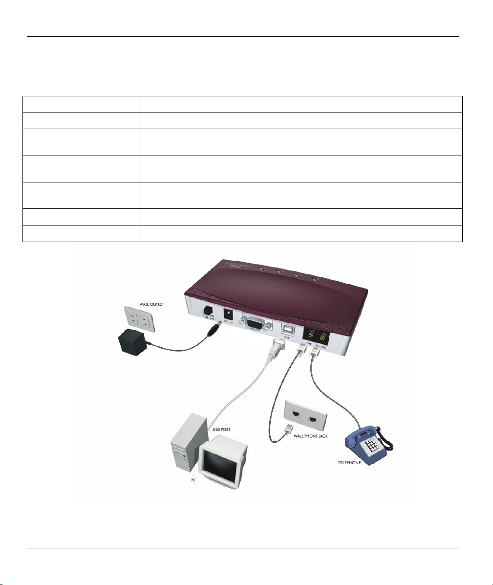
2.1.2 Back Panel
Table 2-3 Back Panel Description
LABEL DESCRIPTION
ON/OFF The power switch for the modem.
AC IN This receptacle is the power input socket and is used to plug the power adapter
into the modem.
RS-232 This serial port DB-9 female connector is used to plug the RS-232 cable from
serial port of a DTE or computer.
USB
(Omni 56K Plus II only)
LINE Connect this analog RJ-11 port to a wall phone jack.
PHONE Connect this analog RJ-11 port to your telephone.
A Universal Serial Bus connector that connects to the USB port on your
computer or to an USB hub.
Figure 2-1 Omni 56K Plus II Rear Panel and Connections
2-2 Installation
Page 19

Omni 56K II and Omni 56K Plus II User’s Guide
The rear panel for the Omni 56K Plus II is identical to the rear panel of the Omni 56K Plus II, except that the
Omni 56K II does not have the USB port.
2.2 Connecting Your Omni 56K II (RS-232 Port)
Step 1. Connect your modem to your analog phone or fax.
Step 2. Use the phone cord included to connect to the phone jack on the wall.
Step 3. Plug one end of your RS-232 cable to your modem and the other end to your computer's serial
port.
Step 4. Use the included power adaptor to connect your modem to the power outlet. Turn on the
modem
Step 5. Turn on your computer and insert the included CD.
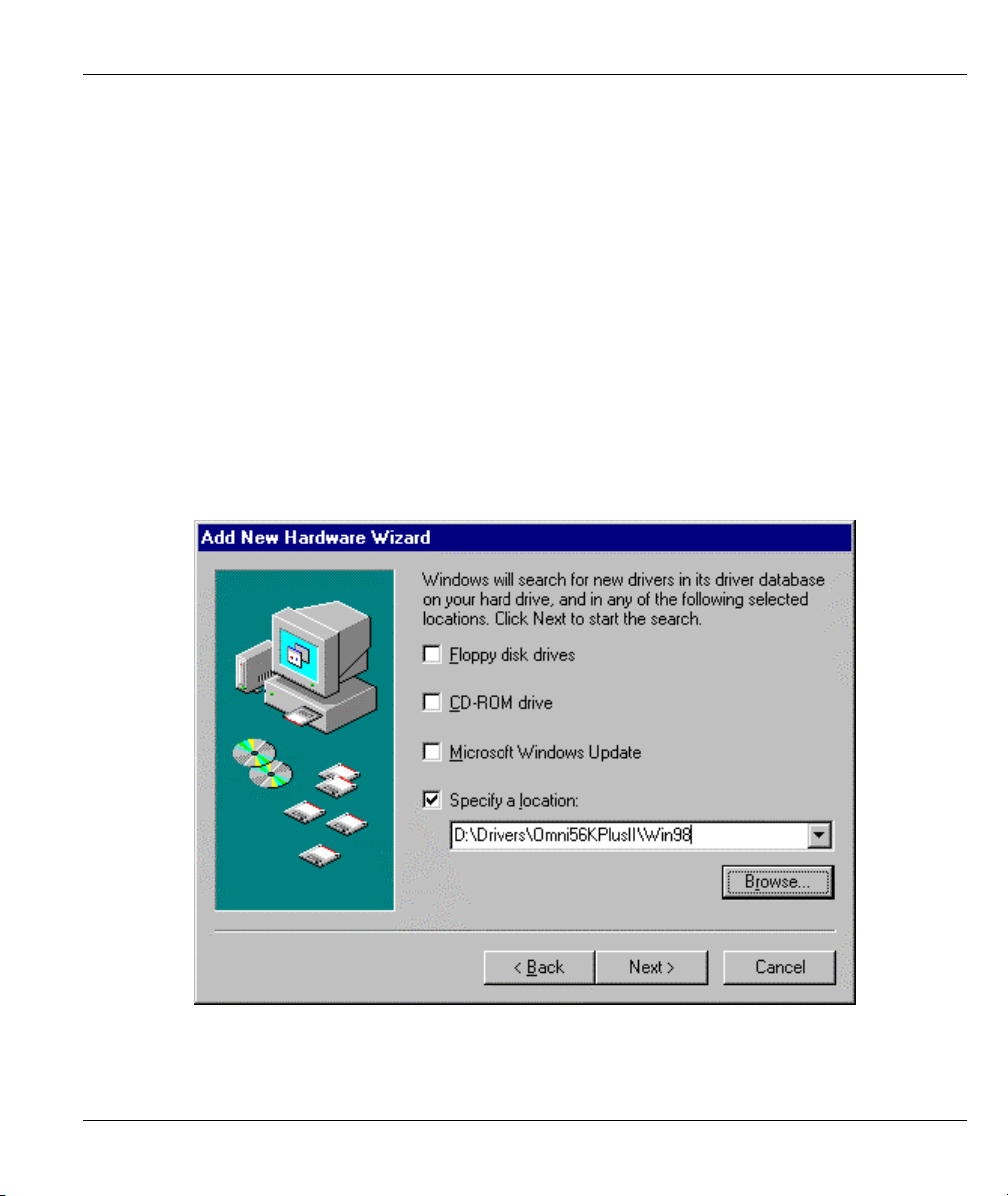
2.2.1 Driver Installation
Windows automatically starts an installation wizard when it detects new hardware. Use the wizard to select
the driver on your included CD. Browse to D:\Drivers\Omni56KII (where D: is your CD-ROM drive), and
click Next or OK.
Installation 2-3
Page 20
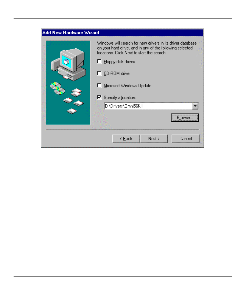
Omni 56K II and Omni 56K Plus II User’s Guide
Figure 2-2 Windows 98 Add New Hardware Wizard
2-4 Installation
Page 21
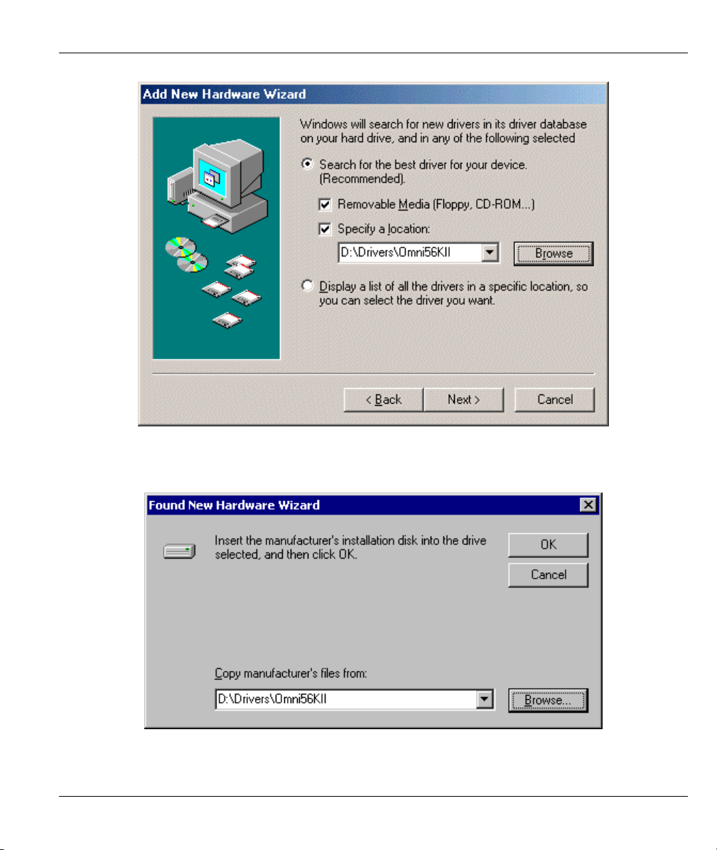
Omni 56K II and Omni 56K Plus II User’s Guide
Figure 2-3 Windows Me Add New Hardware Wizard
Figure 2-4 Windows 2000 Found New Hardware Wizard
Installation 2-5
Page 22
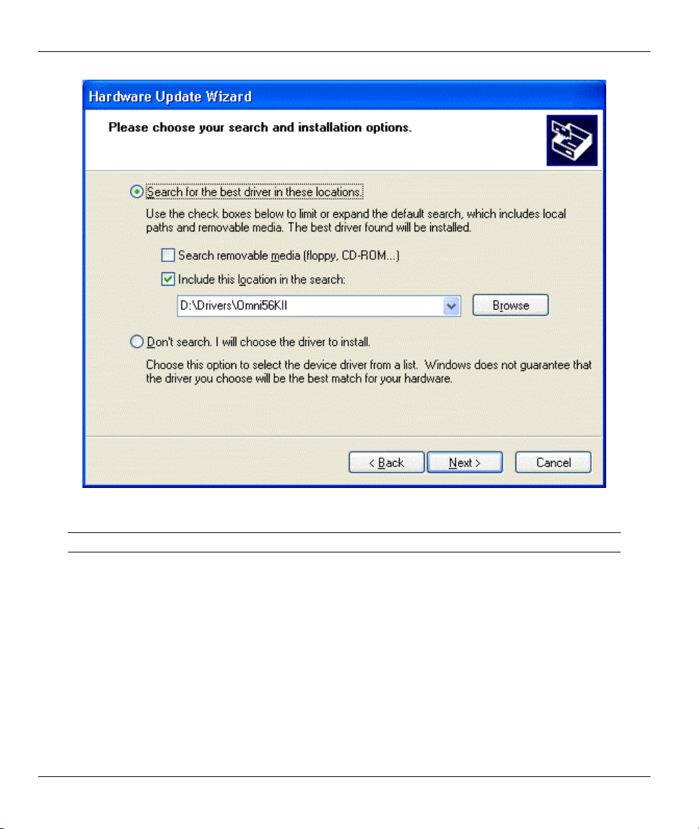
Omni 56K II and Omni 56K Plus II User’s Guide
Figure 2-5 Windows XP Hardware Update Wizard
Click Yes or Continue Anyway if a warning screen appears.
Restart your computer if prompted.
If Windows does not automatically detect your modem, make sure that the modem is connected and turned
on. Then restart your computer or use the add new hardware option in Control Panel to start the installation
wizard. Browse on the CD to the location described above.
2-6 Installation
Page 23
Omni 56K II and Omni 56K Plus II User’s Guide
2.3 Connecting Your Omni 56K Plus II (USB Port)
Step 1. Connect your modem to your analog phone or fax.
Step 2. Use the phone cord included to connect to the phone jack on the wall.
Step 3. Plug one end of your USB cable to your modem and the other end to your computer's USB port.
Step 4. Use the included power adaptor to connect your modem to the power outlet. Turn on the
modem.
Step 5. Insert the included CD into your CD-ROM drive.
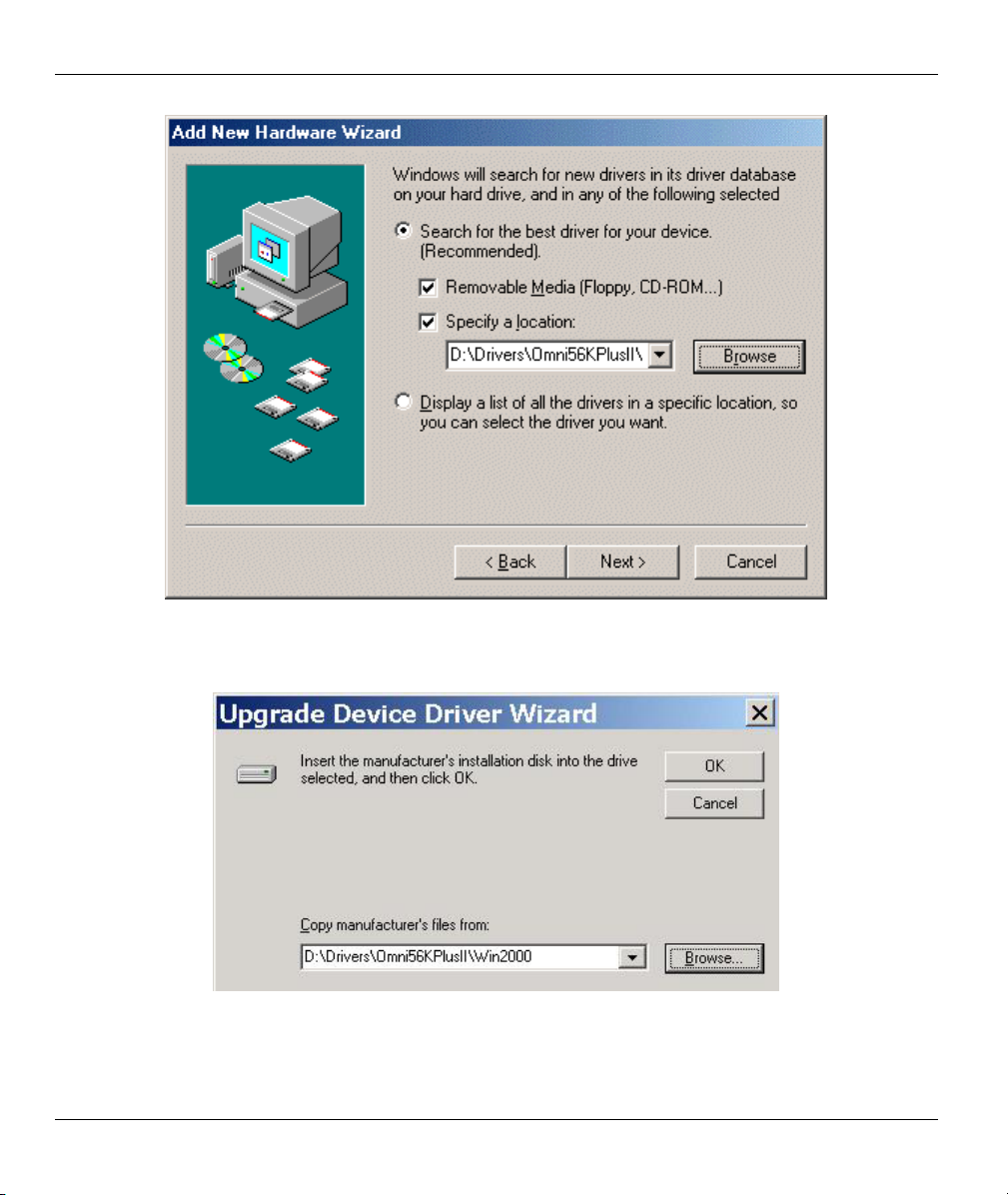
2.3.1 Driver Installation
Windows automatically starts an installation wizard when it detects new hardware. Use the wizard to select
the driver on your included CD. Browse to D:\Drivers\Omni56KPlusII (where D: is your CD-ROM drive)
and the folder for your Windows OS; then click Next or OK.
Figure 2-6 Windows 98 Add New Hardware Wizard
Installation 2-7
Page 24
Omni 56K II and Omni 56K Plus II User’s Guide
Figure 2-7 Windows Me Add New Hardware Wizard
Figure 2-8 Windows 2000 Upgrade Device Driver Wizard
2-8 Installation
Page 25
Omni 56K II and Omni 56K Plus II User’s Guide
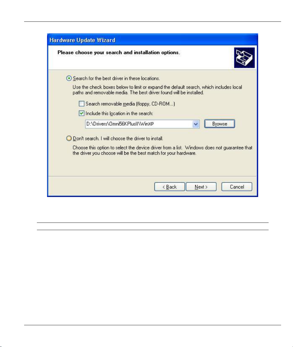
Figure 2-9 Windows XP Hardware Update Wizard
Click Yes or Continue Anyway if a warning screen appears.
Restart your computer if prompted.
If Windows does not automatically detect your modem, make sure that the modem is connected and turned
on. Unplug the USB cable and plug it back in or use the add new hardware option in Control Panel to start
the installation wizard. Browse on the CD to the location described above.
Installation 2-9
Page 26

Omni 56K II and Omni 56K Plus II User’s Guide
2.4 TCP/IP Setup
2.4.1 Installing TCP/IP in Windows 95/98/Me
Click Start, Settings, Control Panel and double-click the Network icon.
Click Add in the Network window Configuration tab.
Select Protocol and then click Add.
Select Microsoft from the list of manufacturers.
Select TCP/IP from the list of network protocols and then click OK.
2.4.2 Configuring TCP/IP in Windows 95/98/Me
In the Network window Configuration tab, select your network adapter’s TCP/IP entry and click
Properties.
Click the IP Address tab. If your ISP gave you an IP address, select Specify an IP address and enter your IP
address and subnet mask. Otherwise, click Obtain an IP address automatically.
Click the DNS Configuration tab. Select Enable DNS, enter your Host name, Domain name, and the DNS
of your ISP, then click OK.
Click the Gateway tab. Highlight any installed gateways and click Remove until none are listed.
Click OK to save and close the TCP/IP Properties window.
Click OK to close the Network window.
Restart your computer if prompted. Insert the Windows CD if prompted.
2.4.3 Configuring TCP/IP in Windows NT/2000/XP
From the Control Panel, click Network and Dial-up Connections (Network Connections in XP) and
right-click your modem’s icon and click Properties.
Select Internet Protocol (TCP/IP) (under the General tab in Win XP) and click Properties.
The Internet Protocol TCP/IP Properties window opens. If your ISP gave you an IP address, select Use
the following IP address: and enter your IP address, subnet mask and default gateway: then select Use the
following DNS server addresses. Otherwise, select Obtain an IP address automatically and Obtain DNS
server automatically.
Click Advanced and remove any installed gateways in the IP Settings tab, then click OK.
Click OK to save and close the TCP/IP Properties window.
2-10 Installation
Page 27
Omni 56K II and Omni 56K Plus II User’s Guide
Click OK to close the Network window.
Restart your computer if prompted. Insert the Windows CD if prompted.
2.5 Dial-Up Networking
Fill in the wizard screens with information from your ISP to create a new dial-up connection.
Windows 98: Click Start, Programs, Accessories, Communications, Dial-Up Networking.
Double-click the Make New Connection icon.
Windows 2000/Me: Click Start, Settings, Network and Dial-Up Connections, Make New Connection.
Windows XP: Click start, All Programs, Accessories, Communications, New Connection Wizard.
After you set up the connection, click or double click the new connection. A pop-up window requests your
username and password.
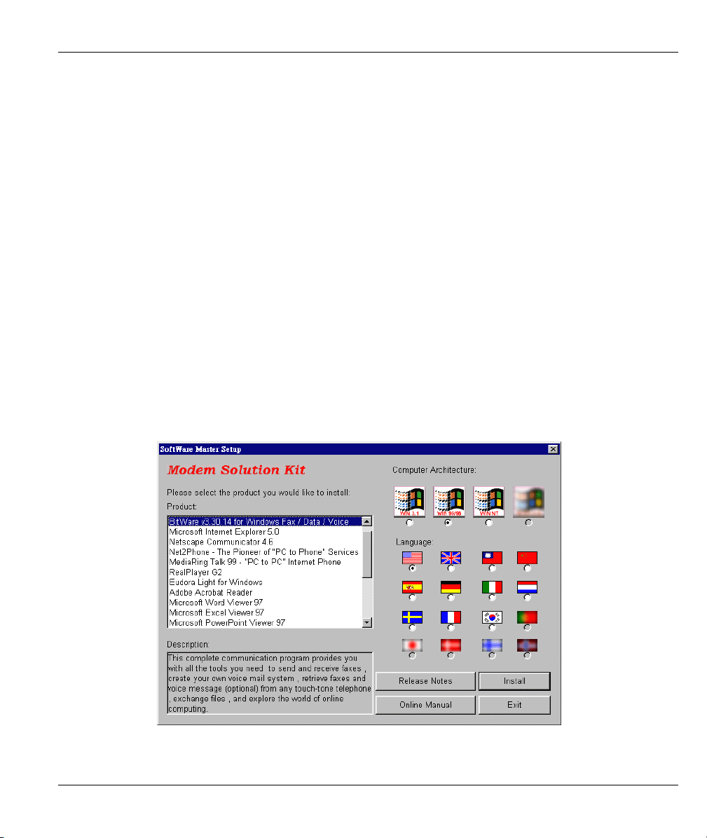
2.6 Installing Bitware From the Included CD
Bitware software lets you transmit faxes or talk on the telephone while using the Internet.
Insert the included CD. Choose the Bitware program from the Product list-box, and select your Windows
system and language on the right side, then click Install. Follow the wizard to complete the installation
process.
Figure 2-10 Bitware Master Setup
Installation 2-11
Page 28

Page 29

Omni 56K II and Omni 56K Plus II User’s Guide
p
Chapter 3
Specifications & Functions
This chapter introduces the specifications and functions of the Omni 56K II and Omni 56K Plus II
modems.
This chapter and the next three chapters are designed for advanced users who might need more information
about the Omni 56K II and Omni 56K Plus II modem's specifications and functions when programming or
using other applications.
3.1 Specifications
3.2 Hardware Specification
Table 3-1 Hardware Specifications
ITEM SPECIFICATION DESCRIPTION
Power Requirements 9V AC
Operating Requirements
Weight 215g
Dimensions 166mm (W) x 40mm (H) x 84mm (L)
Temperature: 0° C to 40° C
Humidity: 5 to 90 % (non-condensing)
3.3 Firmware Specification
Table 3-2 Firmware Specifications
PHYSICAL LAYER FOR DATA
MODE
Specifications and Functions 3-1
Multi-Auto
V.92
V.90
V.34bis 33.6 Kbps to 2.4 Kbps
V.34 28.8 Kbps to 2.4 Kbps
V.32bis 14.4/12/9.6/7.2/4.8 Kbps
V.32 9.6/4.8 Kbps
V.23 1200/600/75 b
s
Page 30

Omni 56K II and Omni 56K Plus II User’s Guide
V.22bis 2.4 Kbps
V.22/Bell 212A 1.2K bps
V.21/Bell 103 300 bps
Auto Fallback/Forward
LINK LAYER
FLOW CONTROL
COMMAND SET
DIAGNOSTICS
FAX
VOICE
MNP 3-4
MNP 5
V42
V42bis
V42 SREJ
V44
Hardware flow control: RTS/CTS
Software flow control: XON/XOFF
Full AT command set
Dialing type: DTMF/Pulse
Power on self test
Analog loop-back test
Analog loop-back with self-test
Local digital loop-back test
Remote digital loop-back test
Remote digital loop-back with self-test
V.17 FAX (send and receive)
V.29 G3 FAX (send and receive)
V.27ter G3 FAX (send and receive)
EIA Class 1 Command Set
EIA Class 2 Command Set
EIA Class 2.0 Command Set
4 bits / sample ADPCM, 9600 samples / second
Online voice playback and recording.
IS-101 voice command set.
3.4 Protocol Support
Data Physical Layer
. ITU-T V.92
. ITU-T V.90
. ITU-T V.34bis/V.34
. ITU-T V.32bis/V.32
3-2 Specifications and Functions
Page 31

. ITU-T V.22bis/V.22
. ITU-T V.21
. ITU-T V.23
. Bell 212A
. Bell 103
Fax Physical Layer
. ITU-T V.17
. ITU-T V.29
. ITU-T V.27ter
. ITU-T V.21
Error Control and Data Compression
. ITU-T V.44
. ITU-T V.42
. ITU-T V.42bis
. MNP3-5
Omni 56K II and Omni 56K Plus II User’s Guide
Command Sets
. Standard command set
. EIA Class 1 Fax Command set
. EIA Class 2.0 Fax Command set
. ZyXEL AT Command set
. IS101 Voice Command set
For more information on detailed command sets, please refer to Chapter 5.
Specifications and Functions 3-3
Page 32

Omni 56K II and Omni 56K Plus II User’s Guide
3.5 Omni 56K II and Omni 56K Plus II Capability
The data/fax/voice feature of Omni 56K II and Omni 56K Plus II is described below:
Table 3-3 Feature Description
FEATURE DESCRIPTION
Data
Fax
Voice
2W Dial-Up Line
Multi-auto/V.92/V.90/V.34bis/V.34/V.32bis/V.32/V.22bis/V.22/ Bell212A
Hardware/Software Flow Control
Error Control/Data Compression
ZyXEL AT Command Set
External Plug and Play for Windows 95/98/2000/Me/XP in RS232 mode
External Plug and Play for Windows 98 /2000/Me/XP in USB mode
Repeat Dial/Cyclic Dial
Caller ID
Distinctive Ring
AT Protection for software application
V.17/V.29/V.27ter
G3 T.30 Protocol
EIA Class 1/ Class 2/ Class 2.0 command set
4 bit IMA ADPCM
Remote Recording on PC storage
IS-101 Command Set
3.6 Data Function
3.6.1 Physical Layer Capability
The Omni 56K II and Omni 56K Plus II modems are high performance universal modems capable of
transmission speeds up to 56/48Kbps full-duplex on a 2-wire dial-up line. Universal compatibility covers a
broad range of ITU-T and BELL standards.
Table 3-4 Physical Layer Capacity
STANDARD BIT RATE [BPS] BAUD RATE
[BAUD]
V.92 – upstream 24000-48000 8000 PCM 0
V.92 – downstream 28000-56000 8000 PCM 0
V.90 28000-56000 8000 PCM 0
3-4 Specifications and Functions
MODULATION CARRIER
FREQUENCY [HZ]
Page 33

Omni 56K II and Omni 56K Plus II User’s Guide
STANDARD BIT RATE [BPS] BAUD RATE
[BAUD]
V.34bis/V.34 2400-33600 multiple TCM multiple
V.32bis 14400 2400 128-TCM 1800
V.32bis 12000 2400 64-TCM 1800
V.32bis 7200 2400 16-TCM 1800
V.32 9600 2400 32-TCM 1800
V.32 uncoded 9600 2400 16-QAM 1800
V.32 4800 2400 4-DPSK 1800
V.23 1200/75 1200/75 FSK
V.23 600/75 600/75 FSK
V.22bis 2400 600 16-QAM 1200 Call
V.22
(BELL 212A)
V.21 300 300 FSK
BELL 103 300 300 FSK
1200 600 4-DPSK 1200 Call
MODULATION CARRIER
FREQUENCY [HZ]
2400 Ans
2400 Ans
3.7 Flow Control
This feature refers to stopping and restarting the flow of data into and out of the modem's transmission and
receiving data buffers. Flow control is necessary so that a device does not receive more data than it can
handle. The Omni 56K II and Omni 56K Plus II provide two kinds of flow control methods.
3.8 Hardware CTS/RTS Flow Control
This is a bi-directional flow control where CTS (Clear to Send) and RTS (Ready to Send) are RS-232 signals
that must be available on your computer. CTS is an RS-232 signal that means the device can send data now.
RTS signifies that the device is now ready to receive data. Both CTS and RTS are hardware methods of flow
control.
Specifications and Functions 3-5
Page 34

Omni 56K II and Omni 56K Plus II User’s Guide
3.9 Software XON/XOFF Flow Control
This is a bi-directional flow control. XON and XOFF character defaults are decimals 17 and 19. These can be
changed by modifying the S-Registers S31 and S32.Both the modem and the DTE will treat XOFF as a
signal to stop transmitting data and will treat XON as a signal to restart sending data. Modems will not send
these characters received from the local DTE to the remote modem.
3.10 Error Control
Error control keeps the modem data link error-free by detecting and re-transmitting erroneous data. The
Omni 56K II and Omni 56K Plus II modems support both MNP and V.42 error control protocols. The MNP
protocol was an industry standard developed and licensed by Microcom, Inc. Omni 56K II and Omni 56K
Plus II modems support level 4 and 3 error control protocols, commonly denoted as MNP4 and MNP3. V42
is a standard developed by CCITT. V.42 supports both LAPM and MNP4. A V.42 handshake will try an
LAPM connection first, and if it is not successful, it will try MNP4.
3.11 Data Compression
In the modem, the data compression is activated to reduce the number of bits actually sent. The receiving
modem applies these techniques in reverse to recover the actual data from the compressed data stream.
The Omni 56K II and Omni 56K Plus II modems support V.44, V.42bis and MNP5 data compression
protocols. Data compression needs an error-free data link to work correctly, otherwise the corrupted
compressed data stream will ruin the decompression process. MNP5 is used with MNP4 error control, V.44
and V.42bis are used with V.42 error control. The compression efficiency of V.42bis is generally higher than
that of MNP5.
3.12 Repeat Dial
The modem will dial the default number stored in non-volatile RAM, EEPROM, repeatedly if not connected.
(s38.0=1,*Dn)
3.13 Cyclic Dial
Dial the number stored in EEPROM at location n(0-3) if cyclic dial s44.3=1 is set. If the first dial is not
successful, the modem will cycle dial through the four numbers stored in memory.
3-6 Specifications and Functions
Page 35

Omni 56K II and Omni 56K Plus II User’s Guide
3.14 Caller Number Delivery (Caller ID)
Caller Number Delivery (CND), commonly called Caller ID, is a feature that may be offered by your local
phone company. Check your phone company for availability. You must subscribe to it and usually pay an
additional monthly service charge for this service.
With CND service, the phone company's central office will send the coded caller information to the called
station. This information is sent once between the first and second ring. Your modem can decode this caller
information and present it to the connected computer/terminal during the second ring period as part of the
call progress ring message. The modem will also report the Caller ID information if asked by the command
AT*T.
There are two kinds of caller information message formats sent by the phone company. One is the single
message format, which includes date, time, and caller ID. The other is the multiple message format, which
also includes the caller name as registered with the phone company.
The command ATS40.2=n is used to enable (n=1) or disable (n=0) the Caller ID detection function. The
default is disabled. Enable it only when you have this service and want to enable its detection.
The Caller ID message may cause some communication software that is not
expecting it to become confused. If you plan to use the Caller ID feature, be sure
you are using software that supports it.
In single message format, the modem will send a ring message to the terminal as follows:
RING
TIME: <MM-DD hh:mm>
CALLER NUMBER: <CALLER_ID> or CALLER NAME:<CALLER_NM>
RING
MM is the two-digit month message, DD is the two-digit date message, hh is the hour and mm is the minute
of the time, and CALLER_ID is the phone number of the caller or CALLER_NM his/her name.
The following is an example of a caller ID message as it might appear on your screen:
RING
TIME: 04-28 12:30
CALLER NUMBER: 7135551414 or CALLER NAME: Brent Harper
Specifications and Functions 3-7
Page 36

Omni 56K II and Omni 56K Plus II User’s Guide
RING
In the multiple message format, if the caller's number and name are available, the ring message will display
both:
RING
TIME: MM-DD hh:mm
CALLER NUMBER: <Caller_ID>
CALLER NAME: <Caller_Name>
RING
Here is an example:
RING
TIME: 04-28 12:30
CALLER NUMBER: 7135551414
CALLER NAME: Tracy Huang
RING
If the caller number and name are not available, the ring message will appear as follows:
RING
TIME: 04-28 12:30
REASON FOR NO NUMBER: OUT_OF_AREA
REASON FOR NO NAME: PRIVACY
RING
The last CND message that the modem received can be displayed by using the AT*T command.
3-8 Specifications and Functions
Page 37

Omni 56K II and Omni 56K Plus II User’s Guide
Setting S48.0=1 will cause the modem to report CND information in its ASCII coded hexadecimal raw data
format. The DTE software is responsible for explaining the data.
Please refer to the Bellcore Technical Advisory document TR-NWT-000030 for the
exact data format. The above Caller ID scheme applies to the North America area.
Different countries may employ different Caller ID schemes, check if the scheme
used in your country is supported before using the Caller ID feature. For most
other Caller ID schemes, only the Caller telephone number is provided.
3.15 Distinctive Ring
Distinctive Ring is a phone service that may be offered by your phone company. Check your phone company
for availability. With this service, you can have several phone numbers assigned to the same phone line. The
phone company will send a different type of ring signal for each phone number being called. The subscriber
can distinguish which number is called by which type of ring is received.
One benefit of this feature is the ability to have three numbers on the same line allowing you to list the three
numbers for voice, data, and fax, respectively. You can then have your fax machine answer only the ring
corresponding to the fax number and have your modem answer only the ring corresponding to the data
number. A voice call will not be answered by either a fax or data machine - it will only be answered when
someone picks up the phone. You can also have the answering machine answer only the voice ring. A more
complicated use is that you can have one number for multiple uses, such as one number for both data and fax.
A ring signal is a composition of repeated on and off states. Different types of rings usually correspond to
different compositions of the "on" part (cadence) of the ring. Your modem can distinguish up to four types of
ring signals and can be commanded to answer or not answer any one of these four types of ring signals.
Following is a list of these four types of ring signals. These are the ring types used in the USA. The
difference among the ring types is the two-second ON part of the ring signal. It comprises a long, double
short, or triple short ring.
S-register S40 bits 3-6 are used for distinctive ring control. Each bit controls the answering of a particular
ring type. Setting a bit to "1" enables answering, setting it to "0" rejects the ring. Note that the ring may still
be heard even if it is not counted as an accepted ring by the modem.
The control relationships between bits 3-6 in register S40 and the different ring types are:
Table 3-5 Different Ring Types in Register S40
TYPE BIT (ON) RING SEQUENCE
1 3 1.2s or 2s on; 4s off
2 4 0.8s on, 0.4s off, 0.8s on; 4s off
Specifications and Functions 3-9
Page 38

Omni 56K II and Omni 56K Plus II User’s Guide
TYPE BIT (ON) RING SEQUENCE
3 5 0.4s on, 0.2s off, 0.4s on, 0.2s off, 0.8s on; 4s off
4 6 0.3s on, 0.2s off, 1s on, 0.2s off, 0.3s on; 4s off
3.16 Security Function
The Omni 56K II and Omni 56K Plus II modems provide a security function, which (when enabled) prevents
an unauthorized user from making a connection. Two types of security function are provided. Type 1 security
is used when the remote modem is also a ZyXEL modem; type 2 security is used when the remote modem is
any other brand of modem.
With the type 1 connection, the dial-in (remote) modem will send in its supervisor password for checking at
the initial connection handshake, and the local modem will check this password against its pre-stored
acceptable password list. With a type 2 connection, the remote terminal will be prompted to enter the
password at the initial connection and the local modem will do the password checking.
Two levels of security are provided. With level 1 security, the local modem will maintain the connection if
the password check is OK, otherwise the line will be disconnected. With level 2 security, the local modem
disconnects the line if the password has been found in its pre-stored acceptable list and then dials back to the
phone number corresponding to the dial-in password. The line is simply disconnected if the password does
not march.
4 user passwords may be defined. The corresponding 4 dial-back numbers are the modem's 4 stored phone
numbers. Any character (ASCII 0-127) can be used in the password field and the maximum password length
is 8 characters.
The security functions are only accessible through AT commands in terminal mode. Any access attempt will
result in the modem's prompting to enter the supervisor password. The attempt will be rejected if the entered
password is not correct. The default supervisor password is ZyXEL when the modem is shipped from the
factory. This supervisor password is also the password sent for automatic password checking in a type 1
connection. To modify the supervisor password, use
AT*HS
You will be asked for the original password and a new password, and then to re-enter the new password for
verification. For example:
PASSWORD (Enter supervisor password)
********
PASSWORD (Enter new supervisor password)
********
3-10 Specifications and Functions
Page 39

Omni 56K II and Omni 56K Plus II User’s Guide
Verify (Enter the new supervisor password again)
********
OK
The command AT*Hn modifies the nth user password and the supervisor password on the screen for
viewing. Again, the modem prompts you enter the supervisor password first.
The commands below enable different types and levels of security:
Table 3-6 Modem Security Function
CODE DESCRIPTION
*G0 Disables security function.
*G1 Enables type 1 and level 1 security, with password check.
*G2 Enables type 1 and level 2 security, with password check and callback.
*G3 Enables type 1 and level 1 security, with password check.
*G4 Enables type 1 and level 2 security, with password check and callback.
*G5 Enables type 2 and level 2 security, with password check and callback,
remote site enters the callback number.
Before the security type or level can be changed, the modem requires the
supervisor password.
For type 2 security, the remote site is prompted to enter the user password. A
maximum of 3 tries in 40 seconds is allowed. If a correct password is not entered
within this time limit, the modem disconnects. If the remote site needs to enter the
callback number, it will be prompted to do so.
Specifications and Functions 3-11
Page 40

Omni 56K II and Omni 56K Plus II User’s Guide
3.17 Fax function
3.17.1 Fax Physical Layer Protocol
Table 3-7 Fax Physical Layer Capacity
STANDARD BIT RATE [BPS] BAUD RATE
[BAUD]
V.17 14400-7200 2400 TCM 1800
V.29 9600-4800 2400 QAM/DPSK 1700
V.27ter 4800-2400 1600/1200 PSK/DPSK 1800
V.21 300 300 FSK
MODULATION CARRIER
FREQUENCY [HZ]
3.17.2 EIA Class 1/Class 2 & Class 2.0 Command Sets
Please refer to Section 5.2 Fax Command Sets.
3.17.3 ITU-T T.30 Fax Protocol
The ITU-T T.30 fax protocol is known as the G3 fax handshake signals and procedures. The modem takes
full control of this protocol - initiating and terminating fax calls, managing the communication session, and
transporting the image data. Therefore, the modem relieves the computer fax software of the T.30 protocol
handling.
You modem allows for fax speeds up to 14400 bps when transmitting to another fax machine that complies
with the V.17 fax standard. Speeds will fall back to 12000, 9600, or 7200 bps in poor line conditions. When
connecting to a G3 fax device, your modem allows for fax speeds up to 9600 bps and will automatically fall
back to 7200, 4800, and 2400 bps if the line quality is poor.
3.18 Voice Function
Voice capability stands for the modem's ability to digitize incoming voice messages, which the computer
stores and forwards. It also means that the modem can playback the recorded digitized voice online for a
message announcement.
3.18.1 Voice IS-101 Command Set
Please refer to the voice command sets Chapter 5.
3-12 Specifications and Functions
Page 41

Omni 56K II and Omni 56K Plus II User’s Guide
3.18.2 4-bit Voice Data Compression
The main issue in the digitized voice mode is the amount of storage required. A relatively simple ADPCM
algorithm can reduce the speech data rate to half the rate and maintain about the same voice quality. This
algorithm can also be used to reduce the speech data rate to 1/3 or 1/4 of the original rate, but with voice
quality degradation. 4-bit ADPCM is used in the Omni 56K II and Omni 56K Plus II modems.
Specifications and Functions 3-13
Page 42

Page 43

Omni 56K II and Omni 56K Plus II User’s Guide
Chapter 4
Result Codes
This chapter details the command responses for the Omni 56K II and Omni 56K Plus II modems.
4.1 Result Codes
The result code is the command response or the Connect message to the DTE. The format of the result code
is dependent on the Xn and Vn commands. The lists are as follows:
Table 4-1 Result Codes
RESULT CODE FOR
ATV0 ATV1
0 OK
1 CONNECT
2 RING
3 NO CARRIER
4 ERROR
5 CONNECT 1200
6 NO DIAL TONE ●
7 BUSY
8 NO ANSWER
9 RINGING
10 CONNECT 2400
11 CONNECT 4800
12 CONNECT 9600
14 CONNECT 19200
15 CONNECT 7200
X0 X1 X2 X3 X4 X5 X6 X7
● ● ● ● ● ● ● ●
● ● ● ● ● ╬ ╬ ╬
● ● ● ● ● ● ● ●
● ● ● ● ● ● ● ●
● ● ● ● ● ● ● ●
● ● ● ● ╬ ╬ ╬
● ● ● ● ●
● ● ● ● ●
● ● ● ● ●
● ● ● ● ╬ ╬ ╬
● ● ● ● ╬ ╬ ╬
● ● ● ● ╬ ╬ ╬
● ● ● ● ╬ ╬ ╬
● ● ● ● ╬ ╬ ╬
● ● ● ●
Result Codes 4-1
Page 44

Omni 56K II and Omni 56K Plus II User’s Guide
RESULT CODE FOR
ATV0 ATV1
16 CONNECT 12000
17 CONNECT 14400
18 CONNECT 16800
19 CONNECT 38400
20 CONNECT 57600
21 CONNECT 76800
22 CONNECT 115200
23 CONNECT 230400
24 CONNECT 460800
25 CONNECT 921600
26 CONNECT 307200
27 CONNECT 153600
28 CONNECT 102400
29 CONNECT 61440
30
31
32
CONNECT 51200
CONNECT624000
CONNECT124800
X0 X1 X2 X3 X4 X5 X6 X7
● ● ● ● ╬ ╬ ╬
● ● ● ● ╬ ╬ ╬
● ● ● ● ╬ ╬ ╬
● ● ● ● ╬
● ● ● ● ╬
● ● ● ● ╬
● ● ● ● ╬
● ● ● ● ╬
● ● ● ● ╬
● ● ● ● ╬
● ● ● ● ╬
● ● ● ● ╬
● ● ● ● ╬
● ● ● ● ╬
●
●
●
●
●
●
●
●
●
●
●
●
╬
●
●
33 CONNECT 62400
34 CONNECT 41600
35 CONNECT 31200
36 CONNECT 24960
37 CONNECT 20800
38 CONNECT 33600
39 CONNECT 28800
40 CONNECT 26400
● ● ● ● ╬
● ● ● ● ╬
● ● ● ● ╬ ╬ ╬
● ● ● ● ╬
● ● ● ● ╬
● ● ● ● ╬ ╬ ╬
● ● ● ● ╬ ╬ ╬
● ● ● ● ╬ ╬ ╬
4-2 Result Codes
Page 45

Omni 56K II and Omni 56K Plus II User’s Guide
RESULT CODE FOR
ATV0 ATV1
41
42
100 CONNECT 56000
101 CONNECT 54666
102 CONNECT 53333
103 CONNECT 52000
104 CONNECT 50666
105 CONNECT 49333
106 CONNECT 48000
107 CONNECT 46666
108 CONNECT 45333
109 CONNECT 44000
110 CONNECT 42666
111 CONNECT 41333
112 CONNECT 40000
CONNECT 24000
CONNECT21600
X0 X1 X2 X3 X4 X5 X6 X7
● ● ● ● ╬ ╬ ╬
● ● ● ● ╬ ╬ ╬
● ● ● ● ╬ ╬ ╬
● ● ● ● ╬ ╬ ╬
● ● ● ● ╬ ╬ ╬
● ● ● ● ╬ ╬ ╬
● ● ● ● ╬ ╬ ╬
● ● ● ● ╬ ╬ ╬
● ● ● ● ╬ ╬ ╬
● ● ● ● ╬ ╬ ╬
● ● ● ● ╬ ╬ ╬
● ● ● ● ╬ ╬ ╬
● ● ● ● ╬ ╬ ╬
● ● ● ● ╬ ╬ ╬
113 CONNECT 38666
114 CONNECT 37333
115 CONNECT 36000
116 CONNECT 34666
117 CONNECT 33333
118 CONNECT 32000
119 CONNECT 30666
120 CONNECT 29333
121 CONNECT 28000
● ● ● ● ╬ ╬ ╬
● ● ● ● ╬ ╬ ╬
● ● ● ● ╬ ╬ ╬
● ● ● ● ╬ ╬ ╬
● ● ● ● ╬ ╬ ╬
● ● ● ● ╬ ╬ ╬
● ● ● ● ╬ ╬ ╬
● ● ● ● ╬ ╬ ╬
● ● ● ● ╬ ╬ ╬
Result Codes 4-3
Page 46

Omni 56K II and Omni 56K Plus II User’s Guide
Note: If error control result codes are enabled (X4, X5, X6, X7), the resulting message will be formatted as:
X4: CARRIER Rx Rate.
PROTOCOL: Error Control Level
COMPRESSION: Compression Level
CONNECT DTE Speed
X5: CONNECT DTE Speed/Protocol Rx Rate/Error control level
X6: CONNECT Rx Rate/ARQ
X7: CONNECT Rx Rate/ARQ/Error control level
ARQ denotes that the Automatic Retransmission reQuest type of error control is enabled.
4-4 Result Codes
Page 47

Omni 56K II and Omni 56K Plus II User’s Guide
Chapter 5
Command Sets
This chapter lists the command sets that the Omni 56K II and Omni 56K Plus II modems support.
These commands include data command sets, fax command sets and voice command sets.
5.1 Data command sets
5.1.1 Basic AT Command Sets
Table 5-1 Basic AT Command Sets
COMMAND OPTIONS FUNCTION & DESCRIPTION REF.
A/ Re-execute the last command once.
A> Re-execute the last command once or repeat the
last call up to 9 times. (See also S8)
<any key> This command terminates the current connection
attempt when entered in handshaking state.
+++ This is the escape sequence code. When entered,
the modem returns to online command mode.
All the Following Commands Require an "AT" Prefix:
Table 5-2 AT Command Sets Requiring an "AT" Prefix
COMMAND OPTIONS FUNCTION & DESCRIPTION REF.
A Go online in answer mode. (See also S39.2,S43.6)
Bn
Command Sets 5-1
Handshake option. S28.7
B0 * Select CCITT V.22 for 1200 bps
B1 Select Bell 212A for 1200 bps communication.
Page 48

Omni 56K II and Omni 56K Plus II User’s Guide
COMMAND OPTIONS FUNCTION & DESCRIPTION REF.
Ds
DL Dials the last-dialed number.
DSn n=0-3 Dial the number stored in non-volatile RAM at
En
Hn
In
Dials (numbers and options) that follow (see also
S38.0, S35.4). The options of s are listed as
follows:
0-9, A,
B,C,D #, *
P Pulse dialing S23.1
T Tone dialing S23.1
, Pause for a time specified in S8. Remaining digits
; Return to command state after dialing.
! Hook flash S56
@ Waits for a 5 second silence before proceeding,
R Reverse handshake. (go online in Answer mode) S17.5
W Wait for the second dial tone. Remaining digits will
Echoes the keyboard commands. S23.0
E0 Echo off
E1 * Echo on
On/off hook control.
H0 * Hang up (on-hook) the modem or ISDN, same as
H1 Sets the modem to off hook.
Displays the inquired information.
I0 Displays the numerical product code, same as
I1 Displays the product information and ROM
Digits for dialing
will be dialed as in-band DTMF.
otherwise returns NO ANSWER.
be dialed as in-band DTMF.
location 'n.'
'ATH.
'ATI.'
checksum.
S44.3
5-2 Command Sets
Page 49

Omni 56K II and Omni 56K Plus II User’s Guide
COMMAND OPTIONS FUNCTION & DESCRIPTION REF.
Ln n=0-7 4 * Speaker volume control. The higher the value, the
Mn
O Returns to online state.
O1 Force the modem to request a retrain.
Qn
Sr.b=n Sets bit 'b' of S-register 'r' to value 'n'. 'n' is a binary
Sr.b? Displays the value of bit 'b' of S-register 'r'
Sr=n Sets S-register 'r' to value 'n'. 'n' must be a decimal
Sr? Displays the value stored in S-register 'r'
T Tone dial S23.1
UPX Download firmware to the Flash EPROM by using
I2 Displays the modem link status report.
I12 Displays the physical layer status.
I13 Displays the channel response for V.34
S24.4-6
higher the volume.
Speaker control S21.1-2
M0 The speaker is always OFF.
M1 * The speaker is ON until carrier detected.
M2 The speaker is always ON.
M3 The speaker is ON after the last digit is dialed out
Tone dialing is not heard.
Displays the result code displayed. S23.7
Q0 * The modem returns the result code.
Q1 The modem does not return the result code.
Q2 The modem returns the result code but is quiet
after answering on a RING. (see also S42.2)
digit '0' or '1'.
number between 0 and 255.
Xmodem protocol.
Sets the display type for result codes. S23.6 Vn
V0 Displays the result code in numeric form. (See also
S35.7 and the result code table of 'ATXn')
S40.1
Command Sets 5-3
Page 50

Omni 56K II and Omni 56K Plus II User’s Guide
COMMAND OPTIONS FUNCTION & DESCRIPTION REF.
V1 * Displays the result code in verbose form.
Xn n=0-7
5 *
Zn
+++ This is the escape sequence code. When entered,
n=0-2 Resets the modem and set power-on profile. S15.5-7
Zn Resets the modem and load user profile n (0-1).
Z2 Resets the modem and load factory settings.
Result code options, see Table 4-1. S23.3-5
the modem returns to online command mode.
5.1.2 Extended AT& Command Sets
Table 5-3 Extended AT& Command Sets
COMMAND OPTIONS FUNCTION & DESCRIPTION REF.
&Bn
&Cn
&Dn
&F Load factory settings to RAM as active configuration.
Data rate, terminal-to-modem. (DTE/DCE) S28.6
&B0 The DTE rate follows the connection rate. (See also
S44.6)
&B1 * The DTE/DCE rates are fixed at the DTE setting
(See also S18, S20, and S44.6)
Carrier Detect (CD) options S21.4
&C0 CD always ON (See also S42.7)
&C1 * CD tracks the presence of carrier (See also S38.3,
S42.7)
Data Terminal Ready (DTR) options. (See also S25) S21.6-7
&D0 Ignore DTR signal, assume DTR is always ON.
&D1 108.1, DTR OFF-ON transition causes dialing of the
default number. (See also 'AT*Dn' and S48.4)
&D2 * 108.2, Data Terminal Ready, DTR OFF causes the
modem to hang up.
&D3 Same as &D2 but DTR OFF causes the modem to
hang up and reset from profile 0.
5-4 Command Sets
Page 51

Omni 56K II and Omni 56K Plus II User’s Guide
COMMAND OPTIONS FUNCTION & DESCRIPTION REF.
&Gn
&Hn
&Kn
&Nn
Guard tone options S28.4-5
&G0 * No guard tone (within USA, Canada).
&G2 1800 Hz guard tone.
Data flow control, DTE/DCE. S27.3-5
&H0 Flow control disabled.
&H3 * Hardware (CTS/RTS) flow control.
&H4 Software (XON/XOFF) flow control.
Modem error control and data compression. S27.0-2
&K0 No error control. (Same as AT&K)
&K1 MNP4 (See also S41.0). (Include MNP3)
&K2 MNP4+MNP5 (See also S38.5, S41.0).
&K3 V.42+MNP4.
&K4 V.42+V.42bis, compatible with &K2 (See also
S38.5).
&K5 * V.42+V.44
Modem link mode options (DCE/DCE). (See S19
also S43.7, S48.1)
&N0 * Multi-Auto, auto-negotiate the highest possible link
rate: .90,V.34bis, V.32bis, V.32, V.22bis, V.22 and
Bell 212A, G3 Fax V.17/V.29/V.27ter.
&N3 V.32 9600T/9600/7200T/4800
&N4 V.32 9600/7200/4800
&N5 V.32 4800
&N12 V.23 1200/75
&N13 V.23 600/75
&N14 V.22bis 2400/1200
&N15 V.22 1200
&N16 V.21 300
&N17 V.32bis 14400/12000/9600/7200/4800
Command Sets 5-5
Page 52

Omni 56K II and Omni 56K Plus II User’s Guide
COMMAND OPTIONS FUNCTION & DESCRIPTION REF.
&N18 V.32bis 12000/9600/7200/4800
&N19 V.32bis 7200/4800
&N24 BELL 212A 1200
&N25 BELL 103 300
&N60 V.34 33600
&N61 V.34 31200
&N62 V.34 28800
&N63 V.34 26400
&N64 V.34 24000
&N65 V.34 21600
&N66 V.34 19200
&N67 V.34 16800
&N68 V.34 14400
&N69 V.34 12000
&N70 V.34 9600
&N71 V.34 7200
&N72 V.34 4800
&N73 V.34 2400
&N99 V.90 28000
&N98 V.90 29333
&N97 V.90 30666
&N96 V.90 32000
&N95 V.90 33333
&N94 V.90 34666
&N93 V.90 36000
&N92 V.90 37333
&N91 V.90 38666
5-6 Command Sets
Page 53

Omni 56K II and Omni 56K Plus II User’s Guide
COMMAND OPTIONS FUNCTION & DESCRIPTION REF.
&Pn
&Rn
&Sn
&Tn
&N90 V.90 40000
&N89 V.90 41333
&N88 V.90 42666
&N87 V.90 44000
&N86 V.90 45333
&N85 V.90 46666
&N84 V.90 48000
&N83 V.90 49333
&N82 V.90 50666
&N81 V.90 52000
&N80 V.90 53333
&N79 V.90 54666
&N78 V.90 56000
Pulse dial make/break ratio. S23.2
&P0 * make / break=39% / 61%
&P1 make / break=33% / 67%
RTS (Request To Send) function selection. S21.5
&R0 CTS tracks RTS, response delay is set in S26.
&R1 * Ignore RTS, assumes RTS is always ON.
Data Set Ready (DSR) function selection. S21.3
&S0 * DSR overridden, DSR is always ON.
&S1 DSR according to CCITT (ITU-TSS). (See also
S41.5, S44.4)
Modem testing. S16
&T0 Terminate the test in progress.
&T1 Initiate an Analog Loop-back (ALB) test.
&T3 Initiate a Local Digital Loop-back (LDL) test.
Command Sets 5-7
Page 54

Omni 56K II and Omni 56K Plus II User’s Guide
COMMAND OPTIONS FUNCTION & DESCRIPTION REF.
&Vn
&W Save the current settings to user profile in
&Yn
&Z? Display all the phone numbers stored in nonvolatile
&Zn=s n=0-3 Store phone number/s to NVRAM at location n (n=0-
&T4 Grant a Remote Digital Loop-back request from a
remote modem.
&T5 Deny a Remote Digital Loop-back request from a
remote modem.
&T6 Initiate a Remote Digital Loop-back (RDL) test.
&T7 Initiate a Remote Digital Loop-back test with self-
test. (RDL+ST)
&T8 Initiate an Analog Loop-back test with self-test.
(ALB+ST)
View the profile settings.
&V0 View the current active settings.
&V1 View the user profile settings.
&V2 View the factory default settings.
nonvolatile RAM. (See also S35.6)
Break handling. Destructive Break clears the buffer.
Expedited Break is sent immediately to the remote
system.
&Y0 Destructive, expedited.
&Y1 * Nondestructive, expedited.
&Y2 Nondestructive, unexpedited.
RAM.
3) use AT*Dn or ATS29=n to set the default dial
pointer.
S14.1
S14.1
S28.2-3
5-8 Command Sets
Page 55

Omni 56K II and Omni 56K Plus II User’s Guide
5.1.3 Extended AT* Command Sets
Table 5-4 Extended AT* Command Sets
COMMAND OPTIONS FUNCTION & DESCRIPTION REF.
*Cn
*En
*Gn
Character length, including start, stop and parity
bit.
*C0 * 10-bit character length
*C1 11-bit character length
*C2 9-bit character length
*C3 8-bit character length
n=0-3 Set the default dial pointer at telephone directory
location 'n.'
*D0 * (See also S35.4 and S38.0)
Modem error control negotiation. S21.0
*E0 * If error control negotiation fails, keep the non-error
control connection.
*E1 If error control negotiation fails, disconnect the call
(hang-up).
*G0 Disables the security function. (Default)
*G1 Enables type 1 security, with password check.
*G2 Enables type 1 security, with password check and
call back.
*G3 Enables type 2 security, with password check.
*G4 Enables type 2 security, with password check and
call back.
*G5 Enables type 2 security, with password check and
call back; remote site enters the callback number.
*G9 Resets the supervisor password to "ZyXEL".
S15.3-4
S29 *Dn
Command Sets 5-9
Page 56

Omni 56K II and Omni 56K Plus II User’s Guide
COMMAND OPTIONS FUNCTION & DESCRIPTION REF.
*Hn N=0-3 Modifies the user password table at location 'n.'
*Pn n=0-15
*Qn
*T Recall the last CND (Caller ID) information. S40.2
*V Views password table.
Note: The command *Gn requests supervisor password checking.
1. In security type 1, the remote site must be a ZyXEL modem.
2. In security type 2, the remote site can be any other type of modem.
3. The modem can store 4 (0-3) telephone numbers. If callback security is disabled, the
modem will search the password table to check the remote modem's password. If they
match, the modem keeps the connection, otherwise the modem will hang up. If callback
security is enabled, the modem will complete the password checking. If there is no match,
the modem disconnects the line, otherwise the modem disconnects the line and find the
corresponding phone number and call back immediately. The remote modem should be set
to automatically answer the call and response.
Modifies the supervisor password. *HS
*P9 *
Action taken when line quality changes. S27.6-7
*Q0 The modem will not act on poor signal quality.
*Q1 Retrain action taken if signal quality is poor. (See
*Q2 * Adaptive rate, automatic fall-back or forward.
*Q3 Disconnect if the signal quality is poor.
Note: The default supervisor password is ZyXEL.
Set transmission power level; ranges from -8 dBm
to -15 dBm. (Default: -11 dBm)
also S41.2)
S17.1-4
5.1.4 Extended AT# Command Sets
Table 5-5 Extended AT# Command Sets
COMMAND OPTIONS FUNCTION & DESCRIPTION REF.
#En
5-10 Command Sets
Modem status in escape state
#E0 This disables the reporting of modem status when it is in escape
state
#E1 This enables the reporting of modem status when in escape state
Page 57

Omni 56K II and Omni 56K Plus II User’s Guide
5.2 Fax Command Sets
5.2.1 Service Class 1 Commands
Table 5-6 Service Class 1 Commands
COMMAND DESCRIPTION VALUE
+FCLASS=n Service Class Identification and Control n=0:Sets to modem mode
n=1:Sets to Class 1 mode
n=2.0:Sets to Class 2.0 mode
n=8:Sets to Voice mode
+FTS=n Stops data transmission and pauses n=0-255 in 10 ms units.
+FRS=n Wait for Silence n=0-255 in 10 ms units.
+FTM=<MOD> Transmit Data with <MOD> Carrier See Table 5-6
+FRM=<MOD> Receive Data with <MOD> Carrier See Table 5-6
+FTH=n Transmit HDLC Data with <MOD>=3 Carrier n=3
+FRH=n Receive HDLC Data with <MOD>=3 Carrier n=3
The value of <MOD> parameters lists as below:
Table 5-7 The Value of <MOD> Parameters
VALUE MODULATION SPEED
3 V.21 ch 2 300
24 V.27ter 2400
48 V.27ter 4800
72 V.29 7200
73 V.17 7200
74 V.17 short train 7200
96 V.29 9600
97 V.17 9600
98 V.17 short train 9600
121 V.17 12000
Command Sets 5-11
Page 58

Omni 56K II and Omni 56K Plus II User’s Guide
122 V.17 short train 12000
145 V.17 14400
146 V.17 short train 14400
5-12 Command Sets
Page 59

Omni 56K II and Omni 56K Plus II User’s Guide
5.2.2 Service Class 2 Commands
The following Class 2 commands are supported and implemented as per TIA PN2388 (8/20/90):
Table 5-8 Service Class 2 Command Syntax
COMMAND SYNTAX DESCRIPTION
+<command>=<value> Execute a command or set a parameter.
+<command>=? Read permissible settings.
+<command>? Read current setting.
Table 5-9 Service Class 2 Commands Supported Commands (per TIA PN2388 8/20/90)
COMMAND DESCRIPTION VALUE
+FAA=n Automatic answer mode parameters.
Answer as set by +FCLASS. n=0
DCE answers and automatically determines the type of call. n=1
+FBADLIN=
<value>
+FBOR=n Phase C data bit order:
Select direct bit order. n=0
Select reversed bit order in receiving mode for phase C data. n=1
+FBUF? Buffer size. This Read Only parameter allows the DTE to determine the
+FCIG="string" Sets the local fax station ID string that is sent to polling Rx.
+FCLASS=n Service class selection. Refer to the +FCLASS Service Class 1 command
+FCON DCE automatically responds to a fax connection.
+FCQ=n Sets the copy quality check capability parameters.
Disables the copy quality check capability. n=0
Bad line threshold (number of consecutive bad lines for a bad page
parameter).
Determine if Copy Quality is OK on the T.30 flow chart. A value of 0
implies that error checking is disabled.
characteristics of the DCE’s buffer size.
in Table 5-6.
0-255
Command Sets 5-13
Page 60

Omni 56K II and Omni 56K Plus II User’s Guide
COMMAND DESCRIPTION VALUE
Only check 1D phase C data. n=1
Check both 1D and 2D phase C data. n=2
+FCR=n "Capability to receive" parameter.
DCE will not receive message data or poll a remote device. n=0
DCE receives message data or polls a remote device. n=1
+FDCC=vr,br,wd,
ln,df,ec,bf,st
Sets Vertical resolution to Normal (98 lpi). vr=0
Sets Vertical resolution to Fine (196 lpi). vr=1
Bit rate: 2400 bit/s; V.27ter. br=0
Bit rate: 4800 bit/s; V.27ter. br=1
Bit rate: 7200 bit/s; V.29 or V.17. br=2
Bit rate: 9600 bit/s; V.29 or V.17. br=3
Bit rate: 12000 bit/s; V.17. br=4
Bit rate: 14400 bit/s; V.17. br=5
Page width: 1728 pixels in 215mm. wd=0
Page width: 2048 pixels in 255mm. wd=1
Page width: 2432 pixels in 303mm. wd=2
Page length: A4; 297mm. ln=0
Page length: B4; 364mm. ln=1
Page length: unlimited length. ln=2
Data compression format: 1-D; modified Huffman. df=0
Data compression format: 2-D; modified Read. df=1
Disables Error correction. ec=0
Disables binary file transfer. bf=0
Minimum scan time/line: 0 ms. st=0
Minimum scan time/line: 5 ms. st=1
Sets the DCE capabilities parameters.
5-14 Command Sets
Page 61

Omni 56K II and Omni 56K Plus II User’s Guide
COMMAND DESCRIPTION VALUE
Minimum scan time/line: 10 ms (normal); 5 ms (fine). st=2
Minimum scan time/line: 10 ms. st=3
Minimum scan time/line: 20 ms (normal); 10ms (fine). st=4
Minimum scan time/line: 20 ms. st=5
Minimum scan time/line: 40 ms (normal); 20ms (fine). st=6
Minimum scan time/line: 40 ms. st=7
+FDCS=vr,br,wd,l
n,df,ec,bf,st
+FDIS=vr,br,wd,l
n,df,ec,bf,st
+FDR This initiates document reception after receiving a phase C data command.
+FDT=df,vr,wd, ln Transmits a phase C data command: release the DCE to proceed with
+FET=n End of page or document command:
More pages; same document. n=0
End of document; another document follows. n=1
No more pages or documents. n=2
Procedure interrupt; another page follows. n=4
Procedure interrupt; end of document, another document follows. n=5
Procedure interrupt; end of document. n=6
+FK Regular fax abort command.
+FLID="string" Local ID string parameter.
+FLO=n Flow control options.
No flow control. n=0
Set the XON/XOFF software flow control. n=1
Set the CTS/RTS hardware flow control. n=2
+FLPL=n This command indicates the availability of documents for polling.
The DTE has no document available for polling. n=0
Current session parameters; refer to the +FDCC command.
Current session negotiation parameters; refer to the +FDCC command.
negotiation.
Command Sets 5-15
Page 62

Omni 56K II and Omni 56K Plus II User’s Guide
COMMAND DESCRIPTION VALUE
Indicates that a document is available for polling. n=1
+FMDL? Request the DCE model.
+FMFR? Request the DCE manufacturer.
+FMINSP=n Minimum phase C speed parameter.
2400 bps. n=0
4800 bps. n=1
7200 bps. n=2
9600 bps. n=3
12000 bps. n=4
14400 bps. n=5
+FPHCTO=
<value>
+FPTS=n Page transfer status
Received page status - good. n=1
Received page status - bad; retrain requested. n=2
Received page status - good; retrain requested. n=3
Received page status - bad; procedure interrupt requested. n=4
Received page status - good; procedure interrupt requested. n=5
+FREL=n Phase C received EOL alignment:
The EOL patterns are bit aligned as received. n=0
The last received bits of EOL patterns are byte aligned by the DCE, with
+FREV? Request the DCE revision identification.
+FSPL=n "Enable polling" command:
Disable polling. n=0
Enable polling. n=1
DTE Phase C response time-out:
Determines how long the DCE will wait for a command after reaching the
end of data when transmitting in Phase C.
<value>=0 to 255; 100 ms units.
necessary zero fill bits inserted. Refer to TIA PN-2388 for details.
0-255
n=1
5-16 Command Sets
Page 63

Omni 56K II and Omni 56K Plus II User’s Guide
All other +F commands are not supported, but the modem will respond OK. In many cases this means "don't
care."
Table 5-10
RESPONSE VALUE FUNCTION AND DESCRIPTION
+FCFR Confirmation.
+FCIG:"string" Reports the remote ID response CIG.
+FCON Facsimile connection response.
+FCSI:"string" Reports the remote ID response CSI.
+FDCS:vr,br,wd,ln,df,
ec,bf,st
+FDIS:vr,br,wd,ln,df,
ec,bf,st
+FDTC:vr,br,wd,ln,df,
ec,bf,st
+FET:n Message response for a received page; refer to the +FET=n command
+FHNG:n
+FNSC:"HEX string" Reports the non-standard facilities command frame.
+FNSF:"HEX string" Reports the non-standard facilities frame response.
+FNSS:"HEX string" Reports the non-standard setup frame response.
+FPOLL Remote polling indication.
+FPTS:n Receive a page transfer status response; refer to the +FPTS=n
Reports the session parameters response; refer to the +FDCC=....
command.
Reports the session negotiation parameters response; refer to the
+FDCC=.... command.
Reports the remote capabilities response; refer to the +FDCC=....
command.
in Table 5-9.
Call termination status response.
n=00 Normal and proper end of connection.
n=10 Transmit error on phase A hang up code.
n=20 Transmit error on phase B hang up code.
n=40 Transmit error on phase C hang up code.
n=50 Transmit error on phase D hang up code.
n=70 Receive error on phase B hang up code.
n=90 Receive error on phase C hang up code.
n=100 Receive error on phase D hang up code.
Class 2 Command Responses
Command Sets 5-17
Page 64

Omni 56K II and Omni 56K Plus II User’s Guide
RESPONSE VALUE FUNCTION AND DESCRIPTION
command.
+FTSI:"string" Report the remote ID response TSI.
+FVOICE Changes to voice response.
Class 2 Flow Control
Flow control is necessary to match the DTE-DCE data rate to the line-signaling rate while transmitting or
receiving Group 3 (T.4) data. In Class 2 fax mode, both hardware (RTS/CTS) and software (XON/XOFF)
flow control are enabled.
5.2.3 Service Class 2.0 Commands
Table 5-11 Service Class 2.0 Commands
COMMAND DESCRIPTION VALUE
+FDT Transmit a phase C data command.
This command releases the DCE to
proceed with the negotiation.
+FDR Receive a phase C data command.
This command initiates document
reception.
+FKS Terminates a Session, orderly fax
abort.
+FIP Initialize the Service Class 2.0
Parameters.
+FCLASS=n Service Class Identification and Control n=0,1,2.0,8;refer to the
+FMI? Identify DCE Manufacturer ZyXEL
+FMM? Identify DCE Omni 56K II/Omni 56K Plus II
+FMR? Identify DCE Revision Vx.x
Establish DCE Capabilities +FCC=vr,br,wd,In,df,ec,bf,st
Vertical Resolution vr=0:Normal;98 lpi
+FCLASS Class 1 command
vr=1:Fine;196 lpi
5-18 Command Sets
Page 65

Omni 56K II and Omni 56K Plus II User’s Guide
COMMAND DESCRIPTION VALUE
+FIS=vr,br,wd,ln,df,ec,bf,st The current session’s negotiating
+FCS=vr,br,wd,ln,df,ec,bf,st The current session’s parameters The same as above
+FLI="string" Local Facsimile station ID String,
+FPI="string" Local Facsimile station ID String, CIG
+FLP=n Indicates a document is available for
+FSP=n Enable/Disable polling n=0:Disable
Bit Rate br=0:2400 bps
br=1:4800 bps
br=2:7200 bps
br=3:9600 bps
br=4:12000 bps
br=5:14400 bps
Page Width wd=0:1728 pixels in 215mm
wd=1:2048 pixels in 255mm
wd=2:2432 pixels in 303mm
Page Length ln=0:A4;297mm
ln=1:B4;364mm
ln=2:unlimited length
Data Compression Format df=0:1-D
df=1:2-D
Error Correction ec=0:Disable
Binary File Transfer bf=0:Disable
Minimum Scan Time/Line st=0:0 ms
st=1:5 ms
st=2:10 ms (normal); 5 ms (fine)
st=3:10 ms
st=4:20 ms (normal); 10 ms
(fine)
st=5:20 ms
st=6:40 ms (normal);20 ms
(fine)
st=7:40 ms
The same as above
parameters
TSI/CSI
n=0:No document
polling
n=1:A document is available
n=1:Enable
Command Sets 5-19
Page 66

Omni 56K II and Omni 56K Plus II User’s Guide
COMMAND DESCRIPTION VALUE
+FNR=rpr,tpr,idr,nsr Enable Negotiation Reporting rpr= 0:Receiver parameters are
not reported.
rpr=1:Receiver parameters are
reported.
tpr= 0:Transmitter parameters
are not reported.
tpr=1:Transmitter parameters
are reported.
idr= 0: ID Strings are not
reported.
idr=1: ID Strings are reported.
nsr= 0:Non-standard frames
are not reported.
nsr= 1:Non-standard frames
are reported.
+FIE=n Procedure Interrupt parameter n=0:Disable
n=1:Enable
+FPS=n Page Transfer Status n=1:Received page is good.
n=2:Page is bad; retrain is
requested.
n=3:Page is good; retrain is
requested.
n=4:Page is bad; procedure
interrupt is requested.
n=5:Page is good; procedure
interrupt is requested.
+FLO=n Flow Control Select n=0:No flow control
n=1:Sets XON/ XOFF software
flow control
n=2:Sets CTS/RTS hardware
flow control
+FPR=n Serial Port Rate Control n=0:Automatic DTE rate
detection by the DCE
n>0:Serial rate is fixed at the
value multiplied by 2400 bps.
+FBO=n Phase C Data Bit Order n=0:Selects direct bit order
n=1:Selects reversed bit order
+FEA=n Phase C Received EOL alignment n=0:EOL patterns are as
received
5-20 Command Sets
Page 67

Omni 56K II and Omni 56K Plus II User’s Guide
COMMAND DESCRIPTION VALUE
+FCR=n Capability to Receive n=0: Do not receive message
data or poll a remote device.
n=1: Receives message data or
polls a remote device.
+FCQ=<rq>,<tq> Copy Quality disable/enable rq= 0:Receive copy quality
check is disabled.
rq=1:Receive copy quality
check is enabled.
tq= 0:Transmit copy quality
check is disabled.
tq=1:Transmit copy quality
check is enabled.
+FRQ=pql,cbl Receive Quality Thresholds pgl= 0-64h:Specifies the
percentage of good lines
cbl= 0-ffh:Specifies the
maximum tolerable number of
consecutive bad lines.
+FAA=n Adaptive Answer Mode n=0:Answers as set by
+FCLASS
n=1:Answers and automatically
determines the call type.
+FCT=n Phase C Timeout n=0-ffh,1 sec units
+FMS=n Minimum Phase C Speed n=0:2400 bps
n=1:4800 bps
n=2:7200 bps
n=3:9600 bps
n=4:12000 bps
n=5:14400 bps
+FBS? Buffer Size 512,256
Command Sets 5-21
Page 68

Omni 56K II and Omni 56K Plus II User’s Guide
5.3 Voice AT Commands
Table 5-12 Voice AT Commands
COMMAND FUNCTION OPTION DEFAULT DESCRIPTION
+FLO Select Flow control. 0,1,2 2 0: NO flow control.
1: (XON/XOFF)Software flow control.
2: (RTS/CTS)Hardware flow control.
+VIP Initialize parameters. N/A N/A +VSD=15,70 (15*4, 7 second)
+VTD=100 (1 second)
+VRN=10 (10 second)
+VRA=70 (7 second)
+VGR=0 (Enable AGC)
+VGT=128
+FLO=2 (RTS/CTS)
+VIT=70 (7 second)
+FCLASS Voice/data/fax
selection
+FMI? Manufacturer ID. N/A ZyXEL
+FMM? Model ID N/A Omni 56K
+FMR? Revision N/A V1.x
+VRX Voice recording N/A N/A Start recording.
+VGR Set the gain for the
received voice
sample.
+VGT Set the gain for the
transmitted voice
sample.
+VLS Select a voice I/O
device.
0,1,2.0,8 0 0: DATA.
1: CLASS 1 FAX.
2.0: CLASS 2.0 FAX.
8: VOICE.
II or Omni
56K Plus II
0 0 0: Automatic gain control (AGC)
0-255 128 0: Silence
1-255: The larger the value, the louder
the voice will be.
0,1 (Omni
56K Plus II
only), 2
0 0: The DCE is on hook. A local phone
is connected to the Telco line.
1: The DCE is on-hook and is
connected to the local phone. Power
is also provided to the local phone.
The modem can record/play through
the local phone set.
5-22 Command Sets
Page 69

Omni 56K II and Omni 56K Plus II User’s Guide
COMMAND FUNCTION OPTION DEFAULT DESCRIPTION
2: The DCE is off-hook and is
connected to the telephone line.
Power is also provided to the local
phone. The modem is able to
record/play through the local
telephone line.
+VRA Ring back goes away
timer
+VRN Ring back never
come timer
+VTX Voice transmit mode N/A N/A Switches to voice transmit mode.
+VSD Silence detection Threshold,
+VSM Selection of
compression method
+VTS= [x,y,z] Dual Tone
Generation
+VTS= {x,y} DTMF Tone
Generation
+VTS= x,x... DTMF Tone
Generation
0 - 255 70 0 : turns off the timer
1-255: Defines the period without
ringback (after at least one ringback
has been detected) in 100 -ms units.
0 - 255 10 0 : turns off the timer
1-255: Defines the period without
ringback after dialing in 1 sec units.
15,70 Threshold:
Period (0-
255), (0-
255)
4;ZyXEL
ADPCM; 4
Bit;(9600)
x: 0-3000
Hz
y: 0-3000
Hz
z: 01000(10ms)
x:0-9,*,#, AD y:0-1000
(10ms)
x:0-9,*,#, A-D N/A x: DTMF digits (0-9,*,#, A,B,C,D)
4,9600 IMA 4 bit ADPCM.
N/A x: first tone frequency
N/A x: DTMF digits (0-9,*,#, A,B,C,D)
0: Disable silence detection.
1-255: The smaller the value, the more
sensitive to the silence detection it will
be.
Period:
1-255: The required period of silence
detection before DCE reports the
silence event.
0: Disable silence detection.
Unit: 0.1 second
Sample rate : 9600
y: second tone frequency
z: duration in 10ms unit
y: duration in 10ms unit
Duration:+VTD setting. (in 10ms unit)
Command Sets 5-23
Page 70

Omni 56K II and Omni 56K Plus II User’s Guide
COMMAND FUNCTION OPTION DEFAULT DESCRIPTION
+VTD Set default duration of
DTMF tone.
+VIT Inactivity timer. 0-255 70 Unit: 0.1 second.
1-255 100 Unit: 0.01 second.
5.4 Voice Shielded DTE Commands
Table 5-13 Voice Shielded DTE Commands
COMMAND DESCRIPTION
<DLE>p Pause, suspend voice data to the output device in playback state.
<DLE>r Resume, resume suspended voice data in playback state.
<DLE><ETX> Terminate voice playback state, switch to online voice command mode after
completing remaining data in buffer.
5.5 Voice Shielded DTE Responses
Table 5-14 Voice Shielded DTE Responses
RESPONSE CODE DESCRIPTION
<DLE>0 - <DLE>9
<DLE>A-<DLE>D
<DLE>*,<DLE>#
<DLE>a Answer Tone detected
<DLE>b Busy detected
<DLE>c Calling Tone detected
<DLE>d Dial tone detected
<DLE>e European Data Modem Calling Tone detected
<DLE>f Bell Answer Tone detected
<DLE>h The local handset is on hook
<DLE>s Silence detected
<DLE>H The local handset is off hook
DTMF digit detected
5-24 Command Sets
Page 71

Omni 56K II and Omni 56K Plus II User’s Guide
RESPONSE CODE DESCRIPTION
<DLE>u Transmission Buffer Underrun. The DCE reports this code if the DEC’s buffer
becomes empty without first receiving a <DLE><ETX> command.
<DLE><ETX> End of stream
5.6 S-Register Descriptions
In most bit-mapped S-registers, the default bit value is 0. An asterisk follows non-0 default values. In some
cases, default values are shown in the reference column preceded by +. Some bits are reserved for factory use
and should not be changed.
5.6.1 Basic S-Registers "ATSn=x"
Table 5-15 Basic S-Registers "ATSn=x"
COMMAND FUNCTION & DESCRIPTION REF.
S0= Sets the number of rings on which the modem will answer. A value of 0 disables
auto-answering.
S1= Counts and stores the number of rings from an incoming call. +000
S2= Defines the escape code character, default ' +' (43 dec.). A value of 128-255 disables
the escape code.
S3= Defines the ASCII Carriage Return. +013
S4= Defines the ASCII Line Feed. +010
S5= Defines the ASCII Backspace key. A value of 128-255 disables the Backspace key' s
delete function.
S6= Sets the number of seconds the modem waits before dialing if ' X0' or ' X1' is
selected. If a setting of ' X2,' 'X7' is selected; the modem will dial as soon as it detects
a dial tone. This register also sets the time-out interval for the "W" dial modifier to
wait for the dial tone. (See also S41b4)
S7= Sets duration, in number of seconds modem waits for a carrier. +060
S8= Sets duration, in seconds, for pause (,) option in Dial command and pause between
command re-executions for Repeat (>) command.
S9= Sets duration, in tenths of a second of remote carrier signal before recognition.
(Ignored if in non-FSK or half-duplex operation)
S10= Sets duration, in tenths of a second, that the modem waits after the carrier is lost
before hanging up.
+000
+043
+008
+003
+002
+006
+007
Command Sets 5-25
Page 72

Omni 56K II and Omni 56K Plus II User’s Guide
COMMAND FUNCTION & DESCRIPTION REF.
S11= Sets duration and spacing, in milliseconds, of dialed Touch-Tones. +070
5.6.2 Extended S-Registers "ATSn=x"
Table 5-16 Extended S-Registers "ATSn=x"
COMMAND BIT DEC HEX FUNCTION AND DESCRIPTION REF.
bit dec hex Bit-mapped register. +000 S13=
S14=
S15=
1 2 2 Captures modem manufacturer information during
V.42 handshake, can be displayed at ATI2 <Last
Speed/Protocol> line if available ('Flash' or 'ZyXEL'
stands for ZyXEL connection).
bit dec hex Bit-mapped register: +002
1 0 0 Grant Remote Digital Loop-back test request. &T4
2 2 Deny Remote Digital Loop-back test request. &T5*
bit dec hex Bit-mapped register. +066
0,1 0 0 Even parity
1 1 Odd parity
2 2 No parity
2 0 0 1 stop bit
4 4 2 stop bits
4,3 0 0 10 bit character length
8 8 11 bit character length
16 10 9 bit character length
24 18 8 bit character length
7-5 0 0 Profile 0 as active settings after power on. Z0
32 20 Profile 1 as active settings after power on. Z1
64 40 Factory default as active settings after power on. Z2*
dec hex Test status register. +000 S16=
0 0 No test in progress. &T0
5-26 Command Sets
Page 73

Omni 56K II and Omni 56K Plus II User’s Guide
COMMAND BIT DEC HEX FUNCTION AND DESCRIPTION REF.
S17=
S18=
S19= dec
S20=
1 1 Analog Loop-back test in progress &T1
3 3 Local Digital Loop-back test in process
6 6 Remote Digital Loop-back test in process
7 7 Remote Digital Loop-back with self-test in process
8 8 Analog Loop-back with self-test in progress. &T8
Bit dec hex Bit-mapped register. +022
4-1 0-30 0-1E Set transmit power level from 0 to -15 dBm. (See also
S35b3) (Default *P11)
5 0 0 Normal dial. (Default) D
32 20 Reverse dial, go online in answer mode. DR
dec hex Force modem to fix baud rate when answering +000
0 0 Disable fixed baud function
1-46 1-2E Enable baud rate to be fixed when answering. Baud
rate value settings (n) the same as S20.
hex
0-99
dec hex DTE speed (bps). Auto detected from AT Command +001
0 0 230400 bps
1 1 115200 bps (Default)
2 2 76800 bps
3 3 57600 bps
4 4 38400 bps
5 5 19200 bps
6 6 16800 bps
7 7 14400 bps
8 8 12000 bps
9 9 9600 bps
10 A 7200 bps
0-63
Modem connection mode, same setting value as
'AT&Nn' command.
*Pn
+000/&Nn
Command Sets 5-27
Page 74

Omni 56K II and Omni 56K Plus II User’s Guide
COMMAND BIT DEC HEX FUNCTION AND DESCRIPTION REF.
Note: Only speeds up to S20=15 are supported by auto-speed detection.
S21=
11 B 4800 bps
12 C 2400 bps
13 D 1200 bps
14 E 460800 bps
15 F 300 bps
16 10 307200 bps
17 11 153600 bps
18 12 102400 bps
20 14 61440 bps
21 15 51200 bps
22 16 624000 bps
24 18 124800 bps
25 19 62400 bps
26 1A 41600 bps
27 1B 31200 bps
28 1C 24960 bps
29 1D 20800 bps
46 2E 921600 bps
bit dec hex Bit-mapped register. +178
0 0 0 Maintain a non-error control connection when a
modem error control handshake fails (default).
1 1 Drop a connection when the modem error control
handshake fails.
1-2 0 0 The speaker is always OFF. M0
2 2 The speaker is ON until the carrier is detected.
(Default)
4 4 The speaker is always ON. M2
*E0
*E1
M1*
5-28 Command Sets
Page 75

Omni 56K II and Omni 56K Plus II User’s Guide
COMMAND BIT DEC HEX FUNCTION AND DESCRIPTION REF.
S23=
6 6 The speaker is ON after the last digit is dialed out the
until carrier is detected.
3 0 0 DSR is always ON (default). &S0
8 8 According to CCITT (see also S44.4, S41.5). &S1
4 0 0 CD is always ON. &C0
16 10 CD tracks the presence of the data carrier (see also
S38.3) (default).
5 0 0 CTS follows RTS in synchronous mode. The response
delay is set in S26.
32 20 Ignore RTS (CTS always ON) in synchronous mode.
(Default)
6-7 0 0 Assume DTR is always ON. &D0
64 40 108.1, DTR OFF-ON transition causes the modem to
dial the default number.
128 80 108.2 Data Terminal Ready, DTR OFF causes the
modem to hang up and return to the command state
(default)
192 C0 108.2, DTR OFF causes the modem to hang up and
reset the modem to profile 0 after the DTR is dropped.
bit dec hex Bit-mapped register. +105
0 0 0 Command echo disabled. E0
1 1 Command echo enabled (default). E1
1 0 0 Tone dial (default). T
2 2 Pulse dial. P
2 0 0 Pulse dial make/break ratio = 39% / 61% (default). &P0
4 4 Pulse dial make/break ratio = 33% / 67%. &P1
3-5 0 0 ATX0 (see result code table). X0
8 8 ATX18 X1
16 10 ATX2 X2
24 18 ATX3 X3
M3
&C1
&R0
&R1
&D1
&D2
&D3
Command Sets 5-29
Page 76

Omni 56K II and Omni 56K Plus II User’s Guide
COMMAND BIT DEC HEX FUNCTION AND DESCRIPTION REF.
S25= 0 to
S27=
32 20 ATX4 X4
40 28 ATX5, error control result code is enabled (default). X5
48 30 ATX6, error control result code is enabled. X6
56 38 ATX7, error control result code is enabled. X7
6 0 0 Displays the result code in numeric format (see
S35.7).
64 40 Displays the result code in verbose format (default). V1
7 0 0 The modem returns the result code (default). Q0
128 80 The modem does not return the result code (see also
S40.1).
bit dec hex Bit-mapped register. S24=
6-4 16-
112
255
dec hex RTS/CTS delay. +000 S26=
0 to
255
bit dec hex Bit-mapped register. +156
0-2 Modem error control.
0 0 No error control. &K0
1 1 MNP4 + MNP3 (see also S41.0). &K1
2 2 MNP4 + MNP5 (see also S38.5, S41.0). &K2
3 3 V.42+MNP4 &K3
4 4 V.42 + V.42bis (compatible with &K2) (default). &K4*
3-5 0 0 Flow control disabled
24 18 Hardware (RTS/CTS) flow control (default)
32 20 Software (RTS/CTS) flow control
10-70 Speaker volume control, increments of 16 in decimal
value.
0-FF Specify the time delay that the DTR signal needs to be
OFF before it is recognized, in 10 ms units. If S25=0,
the delay time is set to 4 ms.
0-FF Set the delay, in 10 millisecond units between the RTS
and the modem's CTS response in synchronous mode
(see '&Rn' command).
V0
Q1
L0-3
+000
&Rn
5-30 Command Sets
Page 77

Omni 56K II and Omni 56K Plus II User’s Guide
COMMAND BIT DEC HEX FUNCTION AND DESCRIPTION REF.
S28=
S29= 0 to 3 0 to 3 Sets the default dial phone number pointer, use
S31= 0-255 0-FF Holds the ASCII decimal value of the XON +017
S32= 0-255 0-FF Holds the ASCII decimal value of the XOFF +019
S35=
40 28 Reserved
6-7 Signal quality.
0 0 No response to poor signal quality. *Q0
64 40 Retrain action taken if signal quality is poor. *Q1
128 80 Adaptive rate (auto fall-back/forward) when signal
quality changes (default).
192 C0 Disconnect when signal quality is poor. *Q3
bit dec hex +068
2-3 0 0 Destructive, expedited break. &Y0
1 4 Non-destructive, expedited break (default). &Y1
10 8 Non-destructive, un-expedited break. &Y2
4-5 0 0 No guard tone (default). &G0
16 10 550 Hz guard tone. &G1
32 20 1800 Hz guard tone. &G2
6 0 0 The DTE/DCE rate follows link rate (see also s18,
S44b6)
1 64 The DTE/DCE rate is fixed at the DTE setting, range
from 300-460.8 Kbps (default, also see S18, S44b6)
AT&Zn=s to store phone numbers in the Windows
registry.
bit dec hex Bit-mapped register. +032
1 2 2 Disables aborting from the terminal during modem
handshaking.
3 8 8 Add 16dB attenuation to the leased line transmission
power.
5 32 20 Enable Selective Reject in V.42 (default).
*Q2
&B0
+000 *D
Command Sets 5-31
Page 78

Omni 56K II and Omni 56K Plus II User’s Guide
COMMAND BIT DEC HEX FUNCTION AND DESCRIPTION REF.
7 128 80 Enable extended numerical result codes from 50 to 65
when an error corrected connection is made. Use with
ATV0 (see result code table).
S38=
S40=
S41=
bit dec hex Bit-mapped register. +000
0 1 1 Repeatedly dials the default number if not connected. *Dn, S29
3 0 0 CD tracks the carrier (default). &C0
3 8 8 The DCD ON/OFF sequence follows UNIX standard,
DCD ON before connect message is sent, DCD off
after the last DCE response is sent.
4 16 10 Auto-mode fax receiving is disabled, hangs up if a fax
call is received (default).
5 32 20 Disable MNP5 negotiation. &Kn
bit dec hex Bit-mapped register. +032 S39
2 4 4 Reverse the answers. Answer in originating mode. ATA
bit dec hex Bit-mapped register. +000
1 2 2 No result code is displayed in answer mode. Q2
2 4 Enables caller ID detection.
3 8 Enables type 1 ring detection.
4 16 Enables type 2 ring detection.
5 32 Enables type 3 ring detection.
6 64 Enables type 4 ring detection.
bit dec hex Bit-mapped register. +000
0 1 1 Special MNP compatibility. (see also s27.0, S38.5) &Kn
3 8 8 Enable CCITT signals 140 and 141 on EIA-232D
interface.
4 16 10 In X2-X7 setting, modem waits for S6 seconds before
dialing and ignores dial tone detection.
5 32 20 DSR follows DCD and pulses for 0.5 sec after DCD
on-off transition.
6 64 40 Force S0>=2; does not answer on the first ring. S0
V0
S23.6
&C1,
S21.4
&N0
&Sn
5-32 Command Sets
Page 79

Omni 56K II and Omni 56K Plus II User’s Guide
COMMAND BIT DEC HEX FUNCTION AND DESCRIPTION REF.
7 128 80 Ignore calling tone, not to be used as fax detection.
S42=
S43=
S44=
S45= dec
S46= dec hex The CND silence detection interval. +028
bit dec hex Bit-mapped register.
1 2 2 Enables throughput averaging. 2
2 4 4 A CND message forces on even if ATQ2 is set.
3 8 8 This disables the escape sequence code in answer
mode.
4 16 10 This disables the V.17 14,400 Fax in calling mode and
no effect on answering mode.
6 64 40 This disables the 'RINGING' result code. Xn
7 128 80 The DCD is forced on but pulses off for 0.5 second at
carrier loss.
bit dec hex Bit-mapped register. +008
6 64 40 Enable a 1.5 second pause between off-hook and
modem answering.
7 128 80 The modem hangs-up if the line condition does not
permit the modem to run at the highest speed set by
'&Nn' command.
bit dec hex Bit-mapped register. +000
3 8 8 ATDSn initiates auto-dial of the stored numbers
consecutively until a connection is made (cyclic dial).
4 16 10 DSR follows DTR (see also S41.5). &S1
6 64 40 When selected with ‘&B0’, DTE speed is fixed at
38400 when the link speed is above 9600. DTE speed
is fixed at 9600 if the link speed is 7200. If it is below
7200, the DTE speed follows link speed. When
selected with &B1, DTE speed is fixed at the current
rate when an ARQ connection is made. When a nonARQ connection is made, DTE speed follows the link
speed (See also S18).
0-255
hex
0-FF
The delay during which the CND silence detection is
disabled, in 20 ms units (see also S46).
&C0
DSn
&Bn
+100
Command Sets 5-33
Page 80

Omni 56K II and Omni 56K Plus II User’s Guide
COMMAND BIT DEC HEX FUNCTION AND DESCRIPTION REF.
0 to
255
S48=
S52=
bit dec hex Bit-mapped register. +000
0 1 1 This causes CND information to be reported in raw
2 4 4 This enables the sending of data calling tones (CNG).
3 8 8 Reverses the V.23 channel speed. Originate mode
4 16 10 (Works with the &D1 command) DTR ON causes the
bit Dec hex Bit-mapped register. +000
7 0 0 Select 'Mark' as the first signal of the V.23
128 80 Select 'Space' as the first signal of the V.23
bit dec hex +000 S56=
0 to
255
bit dec hex Bit-mapped register. +016 S57=
4 16 10 Enables the reporting of Class 1 capability in response
0-FF To process the CND, silence must be detected for the
specified interval, in 20 ms units.
format.
modem speed (Send/Receive) 1200/75; Answer mode
modem speed (Send/Receive) 75/1200.
modem to dial the default number and DTR OFF
causes the modem to hang-up and reset to profile 0.
When the modem is idle (waiting for a command), it
does not dial any number when DTR changes from
ON to OFF.
handshaking sequence (default).
handshaking sequence (default).
0-FF Hook flash detect time, in units of 10ms. A value of
zero uses country-specific default duration.
to +FCLASS=?
&N12
&N12
&N12
Bit
Dec
Hex
+nnn
Note:
S-register bit number, 'b', used in 'ATSr.b=n' and 'ATSr.b=?'
Decimal value, 'x', used in 'ATSn=x'
Equivalent Hexadecimal value.
Factory default when listed in 'Reference' column.
AT' is omitted when an AT command is referred to in the 'Reference' column.
5-34 Command Sets
Page 81

Omni 56K II and Omni 56K Plus II User’s Guide
Command Sets 5-35
Page 82

Page 83

Omni 56K II and Omni 56K Plus II User’s Guide
Chapter 6
Firmware Upgrade
This section describes how you can upgrade the firmware in your modem.
The ZyXEL Omni 56K II and Omni 56K Plus II provides a firmware upgrade function that allows you to
upgrade the firmware either by upgrade software provided in the supplied CD, or by terminal program such
as Bitware or HyperTerminal. To obtain the latest firmware version, please go to ZyXEL's website site at
http://www.zyxel.com.
6.1 Upgrading by Software
To upgrade the firmware using the provided software, follow the steps listed below:
Step 1. Insert the CD-ROM that comes with your modem package into your CD-ROM drive.
Step 2. Double-click the Zyfwm.exe icon on your CD.
Step 3. You will see the first screen of the ZyXEL F/W upload wizard. Select the COM port that is
connected to your modem, then click Next.
Step 4. Click Browse to find the directory where your latest firmware file is located, then click Next to
start uploading.
Follow the upload wizard to complete the upgrade process. After finishing, you may use your modem again.
To obtain the latest firmware version, please go to ZyXEL's website site at
http://www.zyxel.com.
6.2 Upgrading by Terminal Program
To upgrade the firmware by terminal program, you have to prepare a terminal program first, such as the
terminal function in Bitware or HyperTerminal in Windows, then follow the instructions listed below. For
more information on how to install Bitware on your computer, please refer to the Quick Start Guide that
came with your modem package.
Step 1. Start your terminal program.
Step 2. Type in 'atupx', it will show a message as below:
You have chosen XModem protocol with 128-byte block length and checksum tail to upload the
firmware file to update your modem, data in Flash ROM will be erased!!
Firmware Upgrade 6-1
Page 84

Omni 56K II and Omni 56K Plus II User’s Guide
Are you sure (Y/N)?
Step 3. Be sure you have a new version of firmware file on hand, then click 'Y.' The terminal will
respond:
Erase the flash ROM now. Please wait.
Then, it will continue to show:
Ready to program to flash. Please start upload.
Step 4. Now, select XModem checksum mode to send the new firmware to your modem. Enter the file
name then start uploading.
6-2 Firmware Upgrade
Page 85

Omni 56K II and Omni 56K Plus II User’s Guide
Chapter 7
Troubleshooting
This chapter covers potential problems and the possible solutions.
Table 7-1 Troubleshooting
PROBLEM CORRECTIVE ACTION
None of the LEDs turn on when
I start the modem.
I cannot access the modem via
my computer.
I cannot connect to the Internet. Make sure the Line port is properly connected to the wall jack.
Make sure your modem is turned on and the included power adapter
is connected to it as well as plugged into an appropriate and
functioning power outlet.
Check the RS-232 cable connections between the modem and your
computer (Omni 56K Plus only).
Check the USB cable connections between the modem and your
computer (Omni 56K Plus II only).
Carefully follow the instructions in this User’s Guide to install the
software driver.
Contact technical support if these steps fail to solve the problem.
Make sure the modem’s RS-232 port is connected to your
computer’s serial port (Omni 56K Plus only).
Unplug the USB cable and plug it back in again (Omni 56K Plus II
only).
Restart your computer.
Restart the modem by using the ON/OFF switch on your modem.
Restart your computer.
Make sure that you have entered your ISP connection information
correctly. The password may be case sensitive, so make sure that
the Caps lock key is not turned on.
Make sure that your computer’s TCP/IP settings are configured
properly.
Troubleshooting 7-1
Page 86

Omni 56K II and Omni 56K Plus II User’s Guide
PROBLEM CORRECTIVE ACTION
I cannot get the software driver
to uninstall and reinstall
properly.
Close your Windows applications.
Use the add and remove hardware option in the Windows Control
Panel to remove the modem.
Insert the included CD. If a screen automatically opens, close it.
Unplug the RS-232 cable (Omni 56K Plus only) and plug it back in.
Unplug the USB cable (Omni 56K Plus II only) and plug it back in.
Use the add new hardware option in Control Panel to start the
installation wizard.
Restart your computer if prompted.
7-2 Troubleshooting
Page 87

<
<MOD> parameters........................................ 5-11
4
4-bit Voice Data Compression ........................ 3-13
Omni 56K II and Omni 56K Plus II User’s Guide
Index
Extended S-Registers .....................................5-26
F
Fax command sets..........................................5-11
Firmware Specification......................................3-1
Flash ROM ................................................ 1-3, 6-1
Flow Control ....................... 3-2, 3-4, 3-5, 3-6, 5-20
Front Panel LEDs..............................................2-1
A
Automatic Data/Fax call detection .................... 1-2
B
Back Panel ....................................................... 2-2
Basic S-Registers ........................................... 5-25
Bitware ........................................................... 2-11
C
Caller ID ....................................3-4, 3-7, 3-9, 5-10
Capability................................................. 3-4, 5-21
Command Sets..........................5-1, 5-4, 5-8, 5-10
Connecting Your Omni 56K II to the RS-232 Port
..................................................................... 2-3
Copyright ..............................................................ii
Customer Support ...............................................iv
Cyclic Dial.................................................. 3-4, 3-6
D
Data command sets.......................................... 5-1
Data compression...................................... 1-2, 3-6
Data Function ................................................... 3-4
Dial-Up Networking......................................... 2-11
Distinctive Ring.......................................... 3-4, 3-9
E
Error Control ................................ 3-3, 3-4, 3-6, 4-3
error correction ................................................. 1-2
G
G3 14.4Kbps Fax send/receive .........................1-2
H
Hardware CTS/RTS Flow Control .....................3-5
Hardware Specification .....................................3-1
Hot-swappable ..................................................1-2
I
Installation Wizard.............................................2-7
IS-101 Command Set....................... 1-2, 3-4, 3-12
ITU-T T.30 Fax Protocol..................................3-12
M
MOD................................................................5-11
P
Physical Layer Capability ..................................3-4
Protocol Support ...............................................3-2
R
Repeat Dial ............................................... 3-4, 3-6
Result Codes............................................. 4-1, 5-3
RS-232 plug and play compatible .....................1-1
Index A
Page 88

Omni 56K II and Omni 56K Plus II User’s Guide
S
Security ................................................. 3-10, 3-11
Service Class 1 Commands ............................5-11
Service Class 2.0 Commands .........................5-18
Specifications ....................................................3-1
S-Register Descriptions...................................5-25
T
TCP/IP Setup ..................................................2-10
Troubleshooting ................................................7-1
U
Upgrading..........................................................6-1
USB plug and play compatible.......................... 1-1
V
V.92 56K ...........................................................1-1
Voice AT Commands ......................................5-22
Voice Function ................................................3-12
Voice Shielded DTE Commands..................... 5-24
Z
ZyDAS Fifth Generation Data Pump with V.92
Capability ......................................................1-1
B Index
 Loading...