

Page 1

NXC-8160
Business WLAN Controller
User’s Guide
Version 1.0
6/2007
Edition 1
www.zyxel.com
Page 2

Page 3

About This User's Guide
About This User's Guide
Intended Audience
This manual is intended for people who want to configure the NXC-8160 using the web
configurator. You should have at least a basic knowledge of TCP/IP networking concepts and
topology.
Related Documentation
• Quick Start Guide
The Quick Start Guide is designed to help you get up and running right away. It contains
information on setting up your network and configuring for Internet access.
• Supporting Disk
Refer to the included CD for support documents.
• ZyXEL Web Site
Please refer to www.zyxel.com
certifications.
for additional support documentation and product
User Guide Feedback
Help us help you. Send all User Guide-related comments, questions or suggestions for
improvement to the following address, or use e-mail instead. Thank you!
The Technical Writing Team,
ZyXEL Communications Corp.,
6 Innovation Road II,
Science-Based Industrial Park,
Hsinchu, 300, Taiwan.
E-mail: techwriters@zyxel.com.tw
NXC-8160 User’s Guide
3
Page 4

Document Conventions
Document Conventions
Warnings and Notes
These are how warnings and notes are shown in this User’s Guide.
1 Warnings tell you about things that could harm you or your device.
" Notes tell you other important information (for example, other things you may
need to configure or helpful tips) or recommendations.
Syntax Conventions
• The NXC-8160 wireless switch may be referred to as the “NXC-8160”, the “WLAN
controller” or the “system” in this User’s Guide.
• Product labels, screen names, field labels and field choices are all in bold font.
• A key stroke is denoted by square brackets and uppercase text, for example, [ENTER]
means the “enter” or “return” key on your keyboard.
• “Enter” means for you to type one or more characters and then press the [ENTER] key.
“Select” or “choose” means for you to use one of the predefined choices.
• A right angle bracket ( > ) within a screen name denotes a mouse click. For example,
Maintenance > Log > Log Setting means you first click Maintenance in the navigation
panel, then the Log sub menu and finally the Log Setting tab to get to that screen.
• Units of measurement may denote the “metric” value or the “scientific” value. For
example, “k” for kilo may denote “1000” or “1024”, “M” for mega may denote “1000000”
or “1048576” and so on.
• “e.g.,” is a shorthand for “for instance”, and “i.e.,” means “that is” or “in other words”.
4
NXC-8160 User’s Guide
Page 5
Icons Used in Figures
Figures in this User’s Guide may use the following generic icons.
NXC-8160 Computer Notebook computer
Server Wireless Signal Modem/Router
Access Point
Document Conventions
NXC-8160 User’s Guide
5
Page 6

Safety Warnings
Safety Warnings
1 For your safety, be sure to read and follow all warning notices and instructions.
• Do NOT use this product near water, for example, in a wet basement or near a swimming
pool.
• Do NOT expose your device to dampness, dust or corrosive liquids.
• Do NOT store things on the device.
• Do NOT install, use, or service this device during a thunderstorm. There is a remote risk
of electric shock from lightning.
• Connect ONLY suitable accessories to the device.
• Do NOT open the device or unit. Opening or removing covers can expose you to
dangerous high voltage points or other risks. ONLY qualified service personnel should
service or disassemble this device. Please contact your vendor for further information.
• Make sure to connect the cables to the correct ports.
• Place connecting cables carefully so that no one will step on them or stumble over them.
• Always disconnect all cables from this device before servicing or disassembling.
• Use ONLY an appropriate power adaptor or cord for your device.
• Connect the power adaptor or cord to the right supply voltage (for example, 110V AC in
North America or 230V AC in Europe).
• Not to remove the plug and plug into a wall outlet by itself; always attach the plug to the
power supply first before insert into the wall.
• Do NOT allow anything to rest on the power adaptor or cord and do NOT place the
product where anyone can walk on the power adaptor or cord.
• Do NOT use the device if the power adaptor or cord is damaged as it might cause
electrocution.
• If the power adaptor or cord is damaged, remove it from the power outlet.
• Do NOT attempt to repair the power adaptor or cord. Contact your local vendor to order a
new one.
• Do not use the device outside, and make sure all the connections are indoors. There is a
remote risk of electric shock from lightning.
• CAUTION: RISK OF EXPLOSION IF BATTERY (on the motherboard) IS REPLACED
BY AN INCORRECT TYPE. DISPOSE OF USED BATTERIES ACCORDING TO THE
INSTRUCTIONS. Dispose them at the applicable collection point for the recycling of
electrical and electronic equipment. For detailed information about recycling of this
product, please contact your local city office, your household waste disposal service or the
store where you purchased the product.
• Do NOT obstruct the device ventilation slots, as insufficient airflow may harm your
device.
6
NXC-8160 User’s Guide
Page 7

Safety Warnings
• Antenna Warning! This device meets ETSI and FCC certification requirements when
using the included antenna(s). Only use the included antenna(s).
• If you wall mount your device, make sure that no electrical lines, gas or water pipes will
be damaged.
This product is recyclable. Dispose of it properly.
NXC-8160 User’s Guide
7
Page 8

Safety Warnings
8
NXC-8160 User’s Guide
Page 9

Contents Overview
Contents Overview
Introduction ............................................................................................................................21
Getting to Know Your NXC-8160 ............................................................................................... 23
Introducing the Web Configurator .............................................................................................. 27
Web Configurator ...................................................................................................................33
LAN Screen ............................................................................................................................... 35
Centralized Configuration .......................................................................................................... 41
Wireless LAN ............................................................................................................................. 47
Advanced Screen ...................................................................................................................... 63
Access Points Screen ................................................................................................................ 67
Maintenance Screen .................................................................................................................. 69
Password ................................................................................................................................... 73
Troubleshooting and Specifications ....................................................................................75
Troubleshooting ......................................................................................................................... 77
Product Specifications ............................................................................................................... 81
Appendices and Index ...........................................................................................................85
NXC-8160 User’s Guide
9
Page 10

Contents Overview
10
NXC-8160 User’s Guide
Page 11

Table of Contents
Table of Contents
About This User's Guide ..........................................................................................................3
Document Conventions............................................................................................................4
Safety Warnings........................................................................................................................6
Contents Overview ...................................................................................................................9
Table of Contents....................................................................................................................11
List of Figures .........................................................................................................................15
List of Tables...........................................................................................................................19
Part I: Introduction................................................................................. 21
Chapter 1
Getting to Know Your NXC-8160 ...........................................................................................23
1.1 NXC-8160 Overview ............................................................................................................ 23
1.2 Application for the NXC-8160 .............................................................................................. 23
1.2.1 Wireless Internet Access ............................................................................................ 23
1.2.2 Backup NXC-8160 ..................................................................................................... 24
1.3 Ways to Manage the NXC-8160 .......................................................................................... 25
1.4 Good Habits for Managing the NXC-8160 ........................................................................... 25
1.5 Front Panel LEDs (Lights) ................................................................................................... 25
Chapter 2
Introducing the Web Configurator ........................................................................................27
2.1 Web Configurator Overview ................................................................................................. 27
2.2 Accessing the NXC-8160 Web Configurator ....................................................................... 27
2.3 Navigating the NXC-8160 Web Configurator ....................................................................... 27
2.3.1 Title Bar ...................................................................................................................... 28
2.3.2 Main Window ..............................................................................................................28
2.3.3 Status Screen ........................................................................................................... 28
2.3.4 Navigation Panel ........................................................................................................ 30
2.3.5 About Screen .............................................................................................................30
Part II: Web Configurator ...................................................................... 33
NXC-8160 User’s Guide
11
Page 12

Table of Contents
Chapter 3
LAN Screen..............................................................................................................................35
3.1 LAN and WAN ..................................................................................................................... 35
3.2 IP Address and Subnet Mask .............................................................................................. 35
3.2.1 Private IP Addresses .................................................................................................. 36
3.2.2 Management IP Addresses ........................................................................................ 36
3.3 VLAN ................................................................................................................................... 37
3.3.1 VLAN Tagging ............................................................................................................ 37
3.3.2 VLAN Application Example ........................................................................................ 37
3.4 LAN ...................................................................................................................................... 38
Chapter 4
Centralized Configuration......................................................................................................41
4.1 Introduction to Centralized Configuration ............................................................................ 41
4.2 SSH ................................................................................................................................... 41
4.3 How SSH Works .................................................................................................................. 42
4.4 SSH Implementation on the NXC-8160 ............................................................................... 43
4.4.1 Requirements for Using SSH ..................................................................................... 43
4.5 Centralized Configuration Screen ........................................................................................ 43
Chapter 5
Wireless LAN...........................................................................................................................47
5.1 Wireless LAN Introduction ................................................................................................... 47
5.2 Wireless Security Overview .................................................................................................48
5.2.1 SSID ........................................................................................................................... 48
5.2.2 User Authentication .................................................................................................... 48
5.2.3 Encryption .................................................................................................................. 49
5.2.4 Additional Installation Requirements for Using 802.1x ............................................... 50
5.3 Introduction to RADIUS ....................................................................................................... 50
5.4 Configuring WLAN ............................................................................................................. 50
5.4.1 Rename SSIDs ......................................................................................................... 53
5.5 Configuring Wireless Security ............................................................................................. 54
5.5.1 No Security ................................................................................................................. 56
5.5.2 Static WEP ................................................................................................................. 57
5.5.3 Static WEP + IEEE 802.1x (LEAP) ............................................................................ 59
5.5.4 WPA-PSK ................................................................................................................... 60
5.5.5 WPA ........................................................................................................................... 61
Chapter 6
Advanced Screen....................................................................................................................63
12
6.1 SNMP ................................................................................................................................ 63
6.1.1 SNMP Traps ...............................................................................................................64
6.2 Configuring the Advanced Screen ....................................................................................... 64
NXC-8160 User’s Guide
Page 13

Table of Contents
Chapter 7
Access Points Screen ............................................................................................................67
Chapter 8
Maintenance Screen ...............................................................................................................69
8.1 Maintenance Overview ........................................................................................................ 69
8.2 Configuring Syslog & Monitor ............................................................................................. 70
Chapter 9
Password................................................................................................................................. 73
9.1 Configuring Password ........................................................................................................ 73
Part III: Troubleshooting and Specifications....................................... 75
Chapter 10
Troubleshooting......................................................................................................................77
10.1 Power, Hardware Connections, and LEDs ........................................................................ 77
10.2 NXC-8160 Access and Login ............................................................................................ 78
10.3 Internet Access .................................................................................................................. 79
Chapter 11
Product Specifications...........................................................................................................81
Part IV: Appendices and Index ............................................................. 85
Appendix A Setting up Your Computer’s IP Address..............................................................87
Appendix B IP Addresses and Subnetting ...........................................................................109
Appendix C Pop-up Windows, JavaScripts and Java Permissions ...................................... 119
Appendix D Wireless LANs ..................................................................................................127
Appendix E Legal Information ..............................................................................................141
Appendix F Customer Support .............................................................................................145
Index.......................................................................................................................................151
NXC-8160 User’s Guide
13
Page 14

Table of Contents
14
NXC-8160 User’s Guide
Page 15

List of Figures
List of Figures
Figure 1 Wireless Internet Access ......................................................................................................... 24
Figure 2 Backup NXC-8160 ................................................................................................................... 24
Figure 3 Front Panel ............................................................................................................................... 25
Figure 4 Status Screen ........................................................................................................................... 28
Figure 5 Web Configurator Status Screen ............................................................................................. 29
Figure 6 Web Configurator About Screen ............................................................................................. 31
Figure 7 LAN and WAN ......................................................................................................................... 35
Figure 8 VLAN Application Example ...................................................................................................... 38
Figure 9 LAN .......................................................................................................................................... 39
Figure 10 Centralized Configuration Example ....................................................................................... 41
Figure 11 SSH Communication Over the WAN Example ...................................................................... 42
Figure 12 How SSH Works ..................................................................................................................... 42
Figure 13 Centralized Configuration (Member) ..................................................................................... 43
Figure 14 Centralized Configuration (Master) ....................................................................................... 44
Figure 15 Example of a Wireless Network ............................................................................................. 47
Figure 16 WLAN .................................................................................................................................... 51
Figure 17 WLAN > SSID Table .............................................................................................................. 54
Figure 18 SSID & Security ...................................................................................................................... 55
Figure 19 SSID & Security: None ........................................................................................................... 57
Figure 20 SSID & Security: WEP ........................................................................................................... 58
Figure 21 SSID & Security: Static WEP + IEEE 802.1x (LEAP) ............................................................. 59
Figure 22 SSID & Security: WPA-PSK ................................................................................................... 61
Figure 23 SSID & Security: WPA ........................................................................................................... 62
Figure 24 SNMP Management Model .................................................................................................... 63
Figure 25 Advanced .............................................................................................................................. 65
Figure 26 Access Points ........................................................................................................................ 67
Figure 27 Maintenance .......................................................................................................................... 69
Figure 28 Syslog & Monitor ................................................................................................................... 71
Figure 29 Password ............................................................................................................................... 73
Figure 30 Console Cable DB-9 End Pin Layout ..................................................................................... 82
Figure 31 WIndows 95/98/Me: Network: Configuration .......................................................................... 88
Figure 32 Windows 95/98/Me: TCP/IP Properties: IP Address .............................................................. 89
Figure 33 Windows 95/98/Me: TCP/IP Properties: DNS Configuration .................................................. 90
Figure 34 Windows XP: Start Menu ........................................................................................................ 91
Figure 35 Windows XP: Control Panel ................................................................................................... 91
Figure 36 Windows XP: Control Panel: Network Connections: Properties ............................................. 92
Figure 37 Windows XP: Local Area Connection Properties ................................................................... 92
Figure 38 Windows XP: Internet Protocol (TCP/IP) Properties .............................................................. 93
[Document Title]
15
Page 16

List of Figures
Figure 39 Windows XP: Advanced TCP/IP Properties ........................................................................... 94
Figure 40 Windows XP: Internet Protocol (TCP/IP) Properties .............................................................. 95
Figure 41 Windows Vista: Start Menu ..................................................................................................... 96
Figure 42 Windows Vista: Control Panel ................................................................................................ 96
Figure 43 Windows Vista: Network And Internet .................................................................................... 96
Figure 44 Windows Vista: Network and Sharing Center ......................................................................... 96
Figure 45 Windows Vista: Network and Sharing Center ......................................................................... 97
Figure 46 Windows Vista: Local Area Connection Properties ................................................................ 97
Figure 47 Windows Vista: Internet Protocol Version 4 (TCP/IPv4) Properties ....................................... 98
Figure 48 Windows Vista: Advanced TCP/IP Properties ........................................................................ 99
Figure 49 Windows Vista: Internet Protocol Version 4 (TCP/IPv4) Properties ..................................... 100
Figure 50 Macintosh OS 8/9: Apple Menu ............................................................................................ 101
Figure 51 Macintosh OS 8/9: TCP/IP ................................................................................................... 101
Figure 52 Macintosh OS X: Apple Menu .............................................................................................. 102
Figure 53 Macintosh OS X: Network .................................................................................................... 103
Figure 54 Red Hat 9.0: KDE: Network Configuration: Devices ........................................................... 104
Figure 55 Red Hat 9.0: KDE: Ethernet Device: General .................................................................... 104
Figure 56 Red Hat 9.0: KDE: Network Configuration: DNS ................................................................. 105
Figure 57 Red Hat 9.0: KDE: Network Configuration: Activate .......................................................... 105
Figure 58 Red Hat 9.0: Dynamic IP Address Setting in ifconfig-eth0 ................................................. 106
Figure 59 Red Hat 9.0: Static IP Address Setting in ifconfig-eth0 ..................................................... 106
Figure 60 Red Hat 9.0: DNS Settings in resolv.conf ..........................................................................106
Figure 61 Red Hat 9.0: Restart Ethernet Card ................................................................................... 106
Figure 62 Red Hat 9.0: Checking TCP/IP Properties ......................................................................... 107
Figure 63 Network Number and Host ID ...............................................................................................110
Figure 64 Subnetting Example: Before Subnetting ...............................................................................112
Figure 65 Subnetting Example: After Subnetting ..................................................................................113
Figure 66 Conflicting Computer IP Addresses Example .......................................................................117
Figure 67 Conflicting Computer IP Addresses Example .......................................................................117
Figure 68 Conflicting Computer and Router IP Addresses Example .....................................................118
Figure 69 Pop-up Blocker ......................................................................................................................119
Figure 70 Internet Options: Privacy ...................................................................................................... 120
Figure 71 Internet Options: Privacy ...................................................................................................... 121
Figure 72 Pop-up Blocker Settings ....................................................................................................... 121
Figure 73 Internet Options: Security ..................................................................................................... 122
Figure 74 Security Settings - Java Scripting ......................................................................................... 123
Figure 75 Security Settings - Java ........................................................................................................ 123
Figure 76 Java (Sun) ............................................................................................................................ 124
Figure 77 Mozilla Firefox: Tools > Options ........................................................................................... 125
Figure 78 Mozilla Firefox Content Security ........................................................................................... 125
Figure 79 Peer-to-Peer Communication in an Ad-hoc Network ........................................................... 127
Figure 80 Basic Service Set ................................................................................................................. 128
Figure 81 Infrastructure WLAN ............................................................................................................. 129
16
[Document Title]
Page 17

List of Figures
Figure 82 RTS/CTS ............................................................................................................................. 130
Figure 83 WPA(2) with RADIUS Application Example ......................................................................... 137
Figure 84 WPA(2)-PSK Authentication ................................................................................................. 138
[Document Title]
17
Page 18

List of Figures
18
[Document Title]
Page 19

List of Tables
List of Tables
Table 1 Front Panel LEDs (Lights) ......................................................................................................... 26
Table 2 Title Bar: Web Configurator Icon ............................................................................................... 28
Table 3 Web Configurator Status Screen .............................................................................................. 29
Table 4 Screens Summary .................................................................................................................... 30
Table 5 Web Configurator About Screen ............................................................................................... 31
Table 6 LAN ........................................................................................................................................... 39
Table 7 ZyXEL Centralized Configuration Specifications ....................................................................... 41
Table 8 Centralized Configuration (Member) ......................................................................................... 44
Table 9 Centralized Configuration (Master) ........................................................................................... 44
Table 10 Types of Encryption for Each Type of Authentication ............................................................. 49
Table 11 WLAN ...................................................................................................................................... 52
Table 12 WLAN > SSID Table ................................................................................................................ 54
Table 13 Security Modes ....................................................................................................................... 54
Table 14 SSID & Security ...................................................................................................................... 55
Table 15 SSID & Security: None ............................................................................................................ 57
Table 16 SSID & Security: WEP ............................................................................................................ 58
Table 17 SSID & Security: Static WEP + IEEE 802.1x (LEAP) .............................................................. 59
Table 18 SSID & Security: WPA-PSK .................................................................................................... 61
Table 19 SSID & Security: WPA ............................................................................................................ 62
Table 20 SNMP Traps ............................................................................................................................ 64
Table 21 Advanced ................................................................................................................................ 65
Table 22 Access Points ......................................................................................................................... 67
Table 23 Access Points ......................................................................................................................... 70
Table 24 Syslog & Monitor ..................................................................................................................... 71
Table 25 Password ................................................................................................................................ 73
Table 26 Hardware Specifications ......................................................................................................... 81
Table 27 Firmware Specifications .......................................................................................................... 81
Table 28 Console Port Pin Assignments ............................................................................................... 82
Table 29 Ethernet Cable Pin Assignments ............................................................................................ 82
Table 30 IP Address Network Number and Host ID Example ..............................................................110
Table 31 Subnet Masks ........................................................................................................................111
Table 32 Maximum Host Numbers .......................................................................................................111
Table 33 Alternative Subnet Mask Notation .......................................................................................... 111
Table 34 Subnet 1 .................................................................................................................................113
Table 35 Subnet 2 .................................................................................................................................114
Table 36 Subnet 3 .................................................................................................................................114
Table 37 Subnet 4 .................................................................................................................................114
Table 38 Eight Subnets .........................................................................................................................114
[Document Title]
19
Page 20

List of Tables
Table 39 24-bit Network Number Subnet Planning ...............................................................................115
Table 40 16-bit Network Number Subnet Planning ...............................................................................115
Table 41 IEEE 802.11g ........................................................................................................................ 131
Table 42 Wireless Security Levels ....................................................................................................... 132
Table 43 Comparison of EAP Authentication Types ............................................................................ 135
Table 44 Wireless Security Relational Matrix ...................................................................................... 138
20
[Document Title]
Page 21

PART I
Introduction
Getting to Know Your NXC-8160 (23)
Introducing the Web Configurator (27)
21
Page 22

22
Page 23

CHAPTER 1
Getting to Know Your NXC-8160
This chapter introduces the main features and applications of the NXC-8160.
1.1 NXC-8160 Overview
The NXC-8160 is a WLAN controller that allows you to connect the NWA-8500 access points
(APs) to extend your wireless network. The NXC-8160 centralizes the management of all of
the connected APs. You can maintain the APs through the NXC-8160; thus eliminating the
need to connect to and configure each AP individually. The AP acts as an antenna of the NXC-
8160.
If you have more than one NXC-8160 in your network, you can manage the other NXC8160(s) through a NXC-8160. You can also set one NXC-8160 as the main WLAN controller,
and the other as the backup when the primary is not active or cannot work properly.
The NXC-8160 provides secure wireless connectivity to your wired network. The NWA-8500
supports two radios (wireless transmissions of signals) simultaneously which can be of the
same or different IEEE 802.11 mode. That means both IEEE 802.11b/g and IEEE 802.11a
compatible clients can wirelessly access the wired network behind the NXC-8160 through a
connected access point.
" Only use firmware for your NXC-8160’s specific model.
See Chapter 11 on page 81 for a complete list of features.
1.2 Application for the NXC-8160
Here are some examples of what you can do with your NXC-8160.
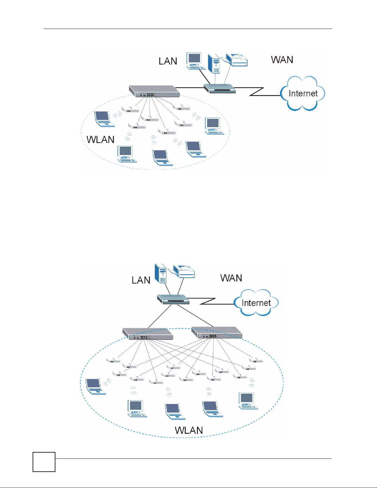
1.2.1 Wireless Internet Access
You can connect a cable or DSL modem/router to the NXC-8160 for broadband Internet
access via an Ethernet port on the modem/router. Both IEEE 802.11a or IEEE 802.11 b/g
wirless clients can access the network behind the NXC-8160 through the access point(s)
connected to the NXC-8160.
NXC-8160 User’s Guide
23
Page 24
Chapter 1 Getting to Know Your NXC-8160
Figure 1 Wireless Internet Access
1.2.2 Backup NXC-8160
To ensure wireless Internet access availability, deploy one NXC-8160 as the main WLAN
controller and the other NXC-8160 as the backup. Both NXC-8160s should be in the same
network and have the same number of connected access points and use the same wireless
settings (such as SSID, channel, IEEE 802.11 mode and security). If the main NXC-8160 fails,
wireless clients can still access the Internet or wired network by connecting to the backup
NXC-8160.
Figure 2 Backup NXC-8160
24
NXC-8160 User’s Guide
Page 25
Chapter 1 Getting to Know Your NXC-8160
1.3 Ways to Manage the NXC-8160
Use any of the following methods to manage the NXC-8160.
• Web Configurator. This is recommended for everyday management of the NXC-8160
using a (supported) web browser.
• Command Line Interface. Line commands are mostly used for troubleshooting by service
engineers.
• SNMP. The device can be monitored by an SNMP manager. See the SNMP chapter in this
User’s Guide.
1.4 Good Habits for Managing the NXC-8160
Do the following things regularly to make the NXC-8160 more secure and to manage the
NXC-8160 more effectively.
• Change the password. Use a password that’s not easy to guess and that consists of
different types of characters, such as numbers and letters.
• Write down the password and put it in a safe place.
" If you forgot the password, you cannot restore the defaults and need to contact
your vendor or customer support.
• Back up the configuration (and make sure you know how to restore it). Restoring an
earlier working configuration may be useful if the device becomes unstable or even
crashes. If you backed up an earlier configuration file, you would not have to totally reconfigure the NXC-8160. You could simply restore your last configuration.
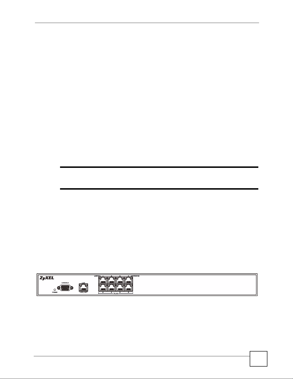
1.5 Front Panel LEDs (Lights)
The following figure shows the front panel of the NXC-8160.
Figure 3 Front Panel
NXC-8160 User’s Guide
25
Page 26
Chapter 1 Getting to Know Your NXC-8160
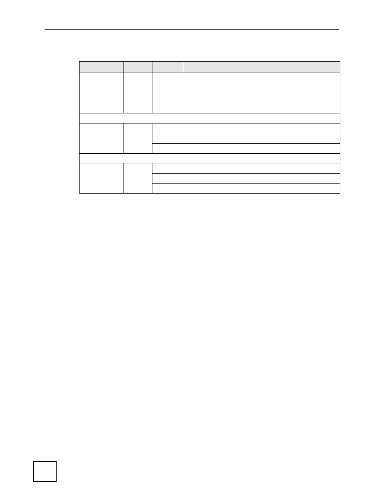
The following table describes the lights on the NXC-8160.
Table 1 Front Panel LEDs (Lights)
LED COLOR STATUS DESCRIPTION
POWER Off The NXC-8160 is turned off.
Green On The NXC-8160 is ready and running.
Flashing The NXC-8160 is restarting.
Red On The power to the NXC-8160 is too low.
LAN
LINK/ACT Off The LAN is not connected.
Green On The NXC-8160 has a successful LAN connection.
Flashing The LAN is sending or receiving packets.
WLAN 1 ~ 8
LINK Green Off The wireless LAN is not ready, or has failed.
On The wireless LAN is ready.
Flashing The wireless LAN is sending or receiving packets.
26
NXC-8160 User’s Guide
Page 27

CHAPTER 2
Introducing the Web
Configurator
This chapter describes how to access the NXC-8160 web configurator and provides an
overview of its screens.
2.1 Web Configurator Overview
The web configurator is an HTML-based management interface that allows easy NXC-8160
setup and management via Internet browser. Use Internet Explorer 6.0 and later or Netscape
Navigator 7.0 and later versions. The recommended screen resolution is 1024 by 768 pixels.
In order to use the web configurator you need to allow:
• Web browser pop-up windows from your device. Web pop-up blocking is enabled by
default in Windows XP SP (Service Pack) 2.
• JavaScripts (enabled by default).
• Java permissions (enabled by default).
See Appendix C on page 119 if you want to make sure these functions are allowed in Internet
Explorer or Netscape Navigator.
2.2 Accessing the NXC-8160 Web Configurator
1 Make sure your NXC-8160 hardware is properly connected and prepare your computer/
computer network to connect to the NXC-8160 (refer to the Quick Start Guide).
2 Launch your web browser.
3 Type “https://” and the IP address of the switch (for example, the default is
192.168.1.10) in the Location or Address field. Press Enter.
4 The login screen appears. The default username is admin and the associated default
password is default.
5 Click OK to view the first web configurator screen.
2.3 Navigating the NXC-8160 Web Configurator
The following summarizes how to navigate the web configurator from the Status screen.
NXC-8160 User’s Guide
27
Page 28
Chapter 2 Introducing the Web Configurator
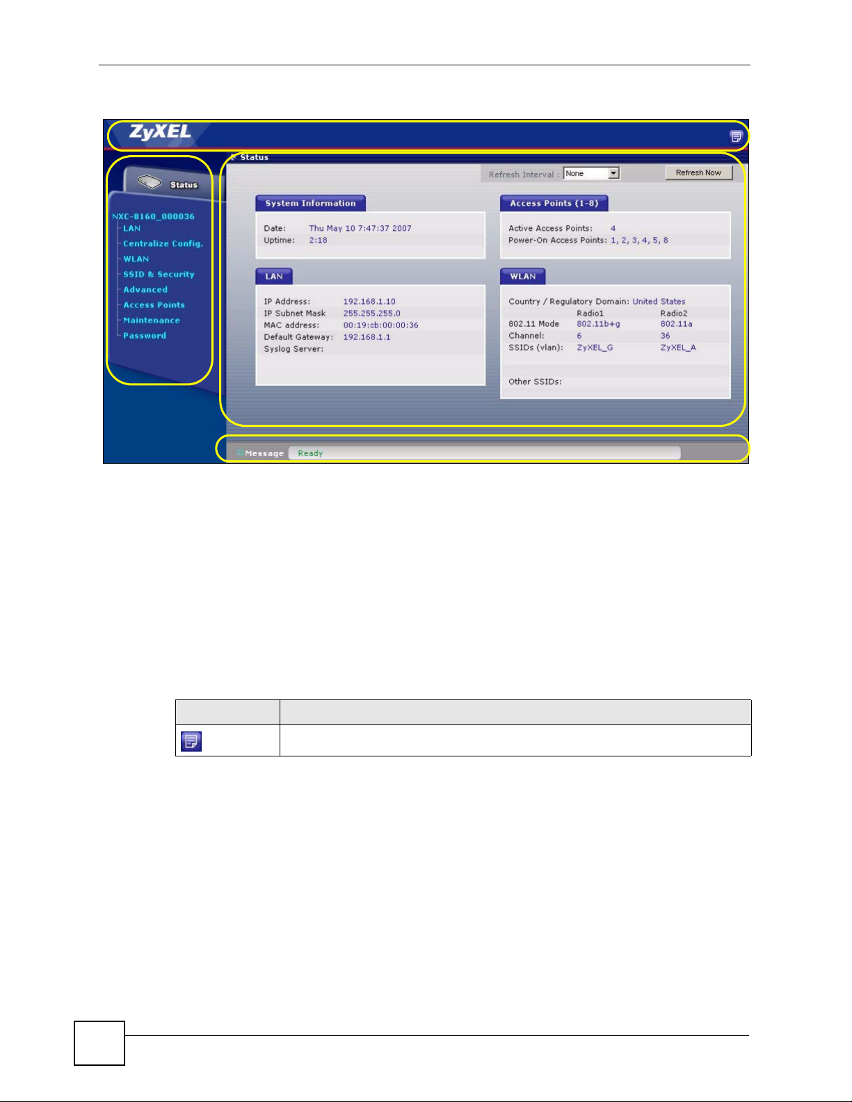
Figure 4 Status Screen
A
D
C
B
As illustrated above, the main screen is divided into these parts:
• A - title bar
• B - main window
• C - status bar
• D - navigation panel
2.3.1 Title Bar
The title bar provides a icon in the upper right corner.
The icon provide the following function.
Table 2 Title Bar: Web Configurator Icon
ICON DESCRIPTION
2.3.2 Main Window
The main window shows the screen you select in the navigation panel. It is discussed in more
detail in the rest of this document.
Right after you log in, the Status screen is displayed.
About: Click this icon to open a screen where you can view the firmware version.
2.3.3 Status Screen
This screen displays general status information about the NXC-8160.
28
NXC-8160 User’s Guide
Page 29
Chapter 2 Introducing the Web Configurator
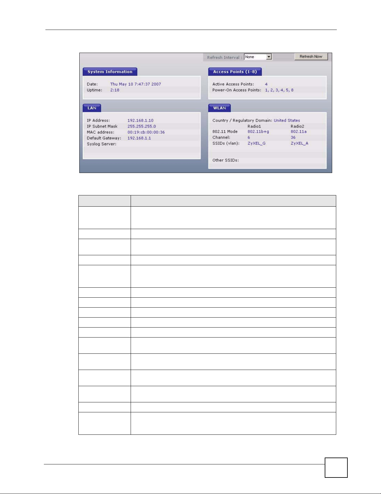
Figure 5 Web Configurator Status Screen
The following table describes the labels in this screen.
Table 3 Web Configurator Status Screen
LABEL DESCRIPTION
Refresh Interval Select a number of seconds or None from the drop-down list box to update all
Refresh Now Click this button to update the status screen statistics immediately.
System
Information
Date This field displays your NXC-8160’s present date and time.
Up Time This field displays how long the NXC-8160 has been running since it last started
LAN
IP Address This shows the LAN port’s IP address.
IP Subnet Mask This shows the LAN port’s subnet mask.
MAC Address This shows the LAN Ethernet adapter MAC Address of your device.
Default Gateway This shows the IP address of the gateway in your network.
Syslog Server This shows the IP address of the server to which the NXC-8160 sends system
Access Points (1-
8)
Active Access
Points
Power-On Access
Points
WLAN
Country /
Regulatory
Domain
screen statistics automatically at the end of every time interval or to not update
the screen statistics.
up. The NXC-8160 starts up when you turn it on, when you restart it or reset to the
defaults (using the Maintenance screen).
logs.
This shows the number(s) of the WLAN port(s) to which an active access point is
connected.
This shows the number(s) of the WLAN port(s) which is enabled to supply power
to an access point.
This shows the country you selected in the WLAN Configuraion screen.
NXC-8160 User’s Guide
29
Page 30
Chapter 2 Introducing the Web Configurator
Table 3 Web Configurator Status Screen (continued)
LABEL DESCRIPTION
802.11 Mode This shows the wireless standard (IEEE 802.11a, b or g) you configured for the
radio (wireless transmissions of signals).
If Radio 2 is disabled, this displays Inactive.
Channel This shows the channel number you configured for the radio.
SSIDs (vlan) This shows the SSID (Service Set IDentity) and the VLAN ID number (if
configured) for the radio.
Other SSIDs This shows the configured SSIDs (if any) which are not assigned to a radio.
2.3.4 Navigation Panel
Use the sub-menus on the navigation panel to configure NXC-8160 features.
The following table describes the sub-menus.
Table 4 Screens Summary
LINK TAB FUNCTION
Status This screen shows the NXC-8160’s general device and network
LAN LAN Use this screen to configure LAN TCP/IP settings.
WLAN WLAN
Configuration
SSID Table Use this screen to rename an SSID.
SSID & Security Use this screen to configure the wireless LAN settings and WLAN
Advanced Use this screen to set up an alternative NXC-8160 as a backup in
Access Points Use this screen to view which AP is active and decide whether to
Maintenance Maintenance Use this screen to change your NXC-8160’s time and date, upload
Syslog &
Monitor
Password Use this screen to change your system passwords.
status information.
Use this screen to configure your WLAN settings for a radio and
create new SSIDs.
security settings for an SSID.
case the primary NXC-8160 fails. You can also use this screen to
send SNMP traps to an SNMP manager.
send power to an AP.
firmware to your NXC-8160, backup and restore the configuration
or reset the factory defaults to your NXC-8160. This screen also
allows you to reboot the NXC-8160 without turning the power off.
Use this screen to enter the IP address of your syslog server and
monitor server.
2.3.5 About Screen
The About screen displays firmware information. To display the screen as shown below, click
the about ( ) button.
30
NXC-8160 User’s Guide
Page 31

Chapter 2 Introducing the Web Configurator
Figure 6 Web Configurator About Screen
The following table describes the read-only fields in this screen.
Table 5 Web Configurator About Screen
LABEL DESCRIPTION
ZyXELFS This field displays the firmware version number and the date created.
AppsFS This field displays the firmware version number and the date created.
RootFs This field displays the date and time when RootFs (used as a placeholder inside
the firmware kernel) was built.
Kernel This field displays the date and time when firmware kernel was built.
Redboot This field displays the Redboot version number and the date created. RedBoot is
an embedded system bootstrap and debug firmware from RedHat.
NXC-8160 User’s Guide
31
Page 32

Chapter 2 Introducing the Web Configurator
32
NXC-8160 User’s Guide
Page 33

PART II
Web Configurator
LAN Screen (35)
Wireless LAN (47)
33
Page 34

34
Page 35

CHAPTER 3
LAN Screen
This chapter describes how to configure LAN settings.
3.1 LAN and WAN
A network is a shared communication system to which many computers are attached.
The Local Area Network (LAN) includes the computers and networking devices (such as the
NXC-8160) in your home or office that you connect to a modem or router’s LAN ports.
The Wide Area Network (WAN) is another network (most likely the Internet) that you connect
to a modem or router. The LAN and the WAN are two separate networks. The following
graphic gives an example.
Figure 7 LAN and WAN
3.2 IP Address and Subnet Mask
Similar to the way houses on a street share a common street name, so too do computers on a
LAN share one common network number.
Where you obtain your network number depends on your particular situation. If the ISP or
your network administrator assigns you a block of registered IP addresses, follow their
instructions in selecting the IP addresses and the subnet mask.
If the ISP did not explicitly give you an IP network number, then most likely you have a single
user account and the ISP will assign you a dynamic IP address when the connection is
established. If this is the case, it is recommended that you select a network number from
192.168.0.0 to 192.168.255.0 and you must enable the Network Address Translation (NAT)
feature of the connected router. The Internet Assigned Number Authority (IANA) reserved
this block of addresses specifically for private use; please do not use any other number unless
NXC-8160 User’s Guide
35
Page 36

Chapter 3 LAN Screen
you are told otherwise. If you select 192.168.1.0 as the network number; it covers 254
individual addresses, from 192.168.1.1 to 192.168.1.254 (zero and 255 are reserved). In other
words, the first three numbers specify the network number while the last number identifies an
individual computer on that network.
Once you have decided on the network number, pick an IP address that is easy to remember,
for instance, 192.168.1.10, for your NXC-8160, but make sure that no other device on your
network is using that IP address.
The subnet mask specifies the network number portion of an IP address. Your NXC-8160 will
compute the subnet mask automatically based on the IP address that you entered. You don't
need to change the subnet mask computed by the NXC-8160 unless you are instructed to do
otherwise.
3.2.1 Private IP Addresses
Every machine on the Internet must have a unique address. If your networks are isolated from
the Internet, for example, only between your two branch offices, you can assign any IP
addresses to the hosts without problems. However, the Internet Assigned Numbers Authority
(IANA) has reserved the following three blocks of IP addresses specifically for private
networks:
• 10.0.0.0 — 10.255.255.255
• 172.16.0.0 — 172.31.255.255
• 192.168.0.0 — 192.168.255.255
You can obtain your IP address from the IANA, from an ISP or it can be assigned from a
private network. If you belong to a small organization and your Internet access is through an
ISP, the ISP can provide you with the Internet addresses for your local networks. On the other
hand, if you are part of a much larger organization, you should consult your network
administrator for the appropriate IP addresses.
" Regardless of your particular situation, do not create an arbitrary IP address;
always follow the guidelines above. For more information on address
assignment, please refer to RFC 1597, Address Allocation for Private Internets
and RFC 1466, Guidelines for Management of IP Address Space.
3.2.2 Management IP Addresses
The NXC-8160 needs an IP address for it to be managed over the network. The factory default
IP address is 192.168.1.10. The subnet mask specifies the network number portion of an IP
address. The factory default subnet mask is 255.255.255.0.
36
NXC-8160 User’s Guide
Page 37

3.3 VLAN
A VLAN (Virtual Local Area Network) allows a physical network to be partitioned into
multiple logical networks. Stations on a logical network can belong to more than one group.
Only stations within the same group can talk to each other. With VLAN, a device cannot
directly talk to or hear from devices that are not in the same group(s) unless such traffic first
goes through a router.
In traditional switched environments, all broadcast packets go to each and every individual
port. With VLAN, all broadcasts are confined to a specific broadcast domain. SSIDs in the
same VLAN group share the same broadcast domain thus increase network performance
through reduced broadcast traffic.
VLAN on the NXC-8160 allows you to:
• Provide security and isolation among the LAN IP addresses and SSIDs.
• Stop an SSID from accessing the Internet.
• Prevent two SSIDs from communicating with each other or allow specific SSIDs to
• Improve network performance.
• Provide different services to different VLAN groups by connecting to another VLAN-
Chapter 3 LAN Screen
communicate with each other.
aware switch.
3.3.1 VLAN Tagging
The NXC-8160 supports IEEE 802.1q VLAN tagging. Tagged VLAN uses an explicit tag
(VLAN ID) in the MAC header of a frame to identify VLAN membership. The NXC-8160 can
identify VLAN tags for incoming Ethernet frames and add VLAN tags to outgoing Ethernet
frames.
" When VLAN is enabled, you must connect the NXC-8160 to a VLAN-aware
device.
3.3.2 VLAN Application Example
In this example, there is an NXC-8160 and a VLAN-aware switch A in your network. The
NXC-8160 is connected to port 4 on switch A. Port 5 on switch A is the uplink port and
connected to the Internet. You configure the following VLAN settings on switch A and the
NXC-8160.
VLAN GROUP
SWITCH A NXC-8160
VLAN 101 Port 1, 4 LAN IP Address
VLAN GROUP MEMBER
NXC-8160 User’s Guide
37
Page 38

Chapter 3 LAN Screen
VLAN 201 Port 2, 4, 5 SSID x
VLAN 301 Port 3, 4, 5 SSID y
This way, the device connected to port 1 on switch A can configure the NXC-8160. Wireless
clients connected to SSID x or y cannot manage the NXC-8160 itself, but they can
communicate with port 2 or 3 on switch A and access the Internet. Wireless clients connected
to SSID x cannot talk to wireless clients connected to SSID y.
Figure 8 VLAN Application Example
" If no devices are in the same VLAN as the NXC-8160 LAN IP address, then
you will not be able to configure the NXC-8160 through the LAN port.
3.4 LAN
Click LAN to open the LAN screen. Use this screen to configure the NXC-8160’s IP address
and other LAN TCP/IP settings.
38
NXC-8160 User’s Guide
Page 39

Chapter 3 LAN Screen
Figure 9 LAN
The following table describes the labels in this screen.
Table 6 LAN
LABEL DESCRIPTION
LAN You can pre-configure two LAN IP addresses, but only one is in use at a time.
192.168.1.10 is the default IP address.
IP Address Type the IP address of your NXC-8160 in dotted decimal notation.
IP Subnet Mask Enter the subnet mask that specifies the network number portion of an IP address.
VLAN (0-4095) Enter the VLAN identification number (between 0 and 4095) for the LAN IP
address. Otherwise, leave this field blank.
The LAN IP address’s VLAN ID should be unique and cannot be in the same VLAN
group as an SSID. That means if you enable VLAN, wireless clients (connected to
an SSID on the NXC-8160) cannot communicate with the LAN IP address to
configure the NXC-8160. With VLAN, an SSID can still access the Internet through
the NXC-8160.
2nd IP Address Enter a second IP address as the NXC-8160’s backup IP address. It should be in a
2nd IP Subnet
Mask
2nd VLAN (0-
4095)
Default Gateway Enter the IP address of the gateway.
System Name Choose a descriptive name for identification purposes. It is recommended you
Apply Click Apply to save your changes back to the NXC-8160.
Reset Click Reset to begin configuring this screen afresh.
NXC-8160 User’s Guide
Note: All centralized configuration members and the master NXC-
8160 should belong to the same VLAN group.
different subnet from the primary one.
Enter the subnet mask that specifies the network number portion of the second IP
address.
Enter the VLAN ID of the second IP address. Otherwise, leave this field blank.
enter your computer’s “Computer name” in this field. This name can be up to 30
alphanumeric characters long. Spaces are not allowed, but dashes “-” and
underscores "_" are accepted.
39
Page 40

Chapter 3 LAN Screen
40
NXC-8160 User’s Guide
Page 41

CHAPTER 4
Centralized Configuration
This chapter describes centralized configuration.
4.1 Introduction to Centralized Configuration
Centralized configuration allows you to configure multiple WLAN controllers through one
controller, called the master controller. The controllers must be able to communicate with one
another.
Table 7 ZyXEL Centralized Configuration Specifications
Maximum number of centralized
configuration members
Centralized configuration Member
Models
Master Controller The device through which you manage the member devices.
Member Controllers The devices being managed by the master device.
In the following example, controller A is the master and the other controllers are members.
Figure 10 Centralized Configuration Example
6
Must be compatible with ZyXEL centralized configuration
implementation.
4.2 SSH
You can use SSH (Secure SHell) to securely access the NXC-8160.
NXC-8160 User’s Guide
41
Page 42

Chapter 4 Centralized Configuration
Unlike Telnet or FTP, which transmit data in plaintext (clear or unencrypted text), SSH is a
secure communication protocol that combines authentication and data encryption to provide
secure encrypted communication between two hosts over an unsecured network. In the
following figure, computer A on the Internet uses SSH to securely connect to the NXC-8160
for a management session.
" If the NXC-8160 is behind a NAT router or a firewall, you need to configure the
router or firewall to allow a SSH connection to the NXC-8160.
Figure 11 SSH Communication Over the WAN Example
4.3 How SSH Works
The following table summarizes how a secure connection is established between two remote
hosts.
Figure 12 How SSH Works
42
NXC-8160 User’s Guide
Page 43

Chapter 4 Centralized Configuration
1 Host Identification
The SSH client sends a connection request to the SSH server. The server identifies itself
with a host key. The client encrypts a randomly generated session key with the host key
and server key and sends the result back to the server.
The client automatically saves any new server public keys. In subsequent connections,
the server public key is checked against the saved version on the client computer.
2 Encryption Method
Once the identification is verified, both the client and server must agree on the type of
encryption method to use.
3 Authentication and Data Transmission
After the identification is verified and data encryption activated, a secure tunnel is
established between the client and the server. The client then sends its authentication
information (user name and password) to the server to log in to the server.
4.4 SSH Implementation on the NXC-8160
Your NXC-8160 supports SSH version 1 and 2 using RSA authentication and three encryption
methods (DES, 3DES and Blowfish). The SSH server is implemented on the NXC-8160 for
management and file transfer on port 22.
4.4.1 Requirements for Using SSH
You must install an SSH client program on a client computer (Windows or Linux operating
system) that is used to connect to the NXC-8160 over SSH.
4.5 Centralized Configuration Screen
Click Centralized Configuration to display the screen as shown next. Use this screen to set
each NXC-8160 as a master or member controller. The screen changes depending on whether
you select the Master Controller check box.
By default, the Master Controller check box is not selected and the NXC-8160 acts as a
member controller.
Figure 13 Centralized Configuration (Member)
NXC-8160 User’s Guide
43
Page 44

Chapter 4 Centralized Configuration
The following table describes the labels in this screen.
Table 8 Centralized Configuration (Member)
LABEL DESCRIPTION
Master Controller Clear the check box to have the NXC-8160 act as a member.
You can manage the member controllers through the master controller.
Save Click Save to save your customized settings in this section.
Upload Master
Controller’s
Public Key
Browse... Type in the location of the file you want to upload in the field next to Browse... or
Sve Click Save to save your customized settings. You should go to the Maintenance
Click the Apply button next to Upload Master Controller’s Public Key to upload
the public key to the NXC-8160.
You should have got the key from the main controller and saved it on your
computer. See Table 9 on page 44 for more information.
click Browse... to find it.
screen and click Apply to have your changes take effect immediately without a
system rebbot.
When you select Master Controller and click Save, the screen changes and displays as shown
next.
Figure 14 Centralized Configuration (Master)
44
The following table describes the labels in this screen.
Table 9 Centralized Configuration (Master)
LABEL DESCRIPTION
SSH Key
Management
Master Controller When you have more than one NXC-8160 in the network, select this to have your
NXC-8160 act as the master controller.
You can manage the member controllers in the same network through the master
controller.
Save Click Save to save your customized settings.
NXC-8160 User’s Guide
Page 45

Chapter 4 Centralized Configuration
Table 9 Centralized Configuration (Master)
LABEL DESCRIPTION
Generate New
SSH Keys
Retrieve Public
SSH Key
Controllers Table This table shows the controllers added to the centralized configuration group. The
Status This field displays which indicates the member controller is accessible.
Name This is the name of a controller you added to this group. To change the name, enter
IP Address This shows the IP address of a controller you added to this group using the fields
Action Select the action that you want to take on the specified member controller.
Save Click Save to save your customized settings in the Controllers Table section.
Reset Click Reset to reload the previous configuration for the Controllers Table section.
Create a New
Ta b l e E n t r y
Name Enter the name of the member controller.
IP Address Enter the IP address of the member controller.
Save Click Save to add a member and display it in the Controllers Table.
Reset Click Reset to clear your configuration in the Create a New Table Entry section.
Click the Save button next to Generate New SSH Keys to have the NXC-8160
create a SSH key which is to be used to identify the NXC-8160 for SSH
connections.
Click the Save button next to Retrieve Public SSH Key to download and save a
public key on your computer, so that you can upload the key to a member.
master controller’s entry is grayed out. You cannot configure it.
a new one, select edit entry in the Action field and then click Save.
below.
Select None to not apply changes to the selected controller.
Select configure controller to apply this NXC-8160’s configuration to the selected
controller.
Select reboot controller to restart the controller.
Select edit entry to configure the controller’s decriptive name.
Select delete entry to remove the controller from this group.
Use the fields below to add a controller to the centralized configuration group.
NXC-8160 User’s Guide
45
Page 46

Chapter 4 Centralized Configuration
46
NXC-8160 User’s Guide
Page 47

CHAPTER 5
Wireless LAN
This chapter discusses how to configure wireless LAN on the NXC-8160.
5.1 Wireless LAN Introduction
A wireless LAN can be as simple as two computers with wireless LAN adapters
communicating in a peer-to-peer network or as complex as a number of computers with
wireless LAN adapters communicating through access points which bridge network traffic to
the wired LAN.
" See the WLAN appendix for more detailed information on WLANs.
The following figure provides an example of a wireless network.
Figure 15 Example of a Wireless Network
NXC-8160 User’s Guide
47
Page 48

Chapter 5 Wireless LAN
In this wireless network, devices A and B are called wireless clients. The wireless clients use
the access point (AP) which is connected to a WLAN controller to interact with other devices
(such as the printer) or with the Internet. Your NXC-8160 is the WLAN controller.
Every wireless network must follow these basic guidelines.
• Every wireless client in the same wireless network must use the same SSID.
The SSID is the name of the wireless network. It stands for Service Set IDentity.
• If two wireless networks overlap, they should use different channels.
Like radio stations or television channels, each wireless network uses a specific channel,
or frequency, to send and receive information.
• Every wireless client in the same wireless network must use security compatible with the
AP.
Security stops unauthorized devices from using the wireless network. It can also protect
the information that is sent in the wireless network.
5.2 Wireless Security Overview
The following sections introduce different types of wireless security you can set up in the
wireless network.
5.2.1 SSID
Normally, the AP acts like a beacon and regularly broadcasts the SSID in the area. You can
hide the SSID instead, in which case the AP does not broadcast the SSID. In addition, you
should change the default SSID to something that is difficult to guess.
This type of security is fairly weak, however, because there are ways for unauthorized devices
to get the SSID. In addition, unauthorized devices can still see the information that is sent in
the wireless network.
5.2.2 User Authentication
You can make every user log in to the wireless network before they can use it. This is called
user authentication. However, every wireless client in the wireless network has to support
IEEE 802.1x to do this.
For wireless networks, there are two typical places to store the user names and passwords for
each user.
• In the AP or WLAN controller: this feature is called a local user database or a local
database.
• In a RADIUS server: this is a server used in businesses more than in homes.
48
If your AP or WLAN controller does not provide a local user database and if you do not have
a RADIUS server, you cannot set up user names and passwords for your users.
NXC-8160 User’s Guide
Page 49

Unauthorized devices can still see the information that is sent in the wireless network, even if
they cannot use the wireless network. Furthermore, there are ways for unauthorized wireless
users to get a valid user name and password. Then, they can use that user name and password
to use the wireless network.
Local user databases also have an additional limitation that is explained in the next section.
5.2.3 Encryption
Wireless networks can use encryption to protect the information that is sent in the wireless
network. Encryption is like a secret code. If you do not know the secret code, you cannot
understand the message.
The types of encryption you can choose depend on the type of user authentication. (See
Section 5.2.2 on page 48 for information about this.)
Table 10 Types of Encryption for Each Type of Authentication
Weakest No Security
Chapter 5 Wireless LAN
NO AUTHENTICATION RADIUS SERVER
WEP
WEP + 802.1x (LEAP)
Strongest WPA-PSK WPA
For example, if the wireless network has a RADIUS server, you can choose WEP + 802.1x
(LEAP) or WPA. If users do not log in to the wireless network, you can choose no encryption,
WEP or WPA-PSK.
Usually, you should set up the strongest encryption that every wireless client in the wireless
network supports. For example, suppose the AP does not have a local user database, and you
do not have a RADIUS server. Therefore, there is no user authentication. Suppose the wireless
network has two wireless clients. Device A only supports WEP, and device B supports WEP
and WPA. Therefore, you should set up WEP in the wireless network.
" It is recommended that wireless clients use WPA-PSK, WPA, or stronger
encryption. IEEE 802.1x and WEP encryption are better than none at all, but it
is still possible for unauthorized devices to figure out the original information
pretty quickly.
" It is not possible to use WPA-PSK, WPA or stronger encryption with a local
user database. In this case, it is better to set up stronger encryption with no
authentication than to set up weaker encryption with the local user database.
NXC-8160 User’s Guide
49
Page 50

Chapter 5 Wireless LAN
Many types of encryption use a key to protect the information in the wireless network. The
longer the key, the stronger the encryption. Every wireless client in the wireless network must
have the same key.
5.2.4 Additional Installation Requirements for Using 802.1x
• A computer with an IEEE 802.11 compatible wireless LAN card.
• A computer equipped with a web browser (with JavaScript enabled) and/or Telnet.
• A wireless station must be running IEEE 802.1x-compliant software. Currently, this is
offered in Windows XP.
• An optional network RADIUS server for remote user authentication and accounting.
5.3 Introduction to RADIUS
The NXC-8160 can use an external RADIUS server to authenticate users. RADIUS is based
on a client-sever model that supports authentication and accounting, where access point is the
client and the server is the RADIUS server.
• Authentication
Determines the identity of the users.
• Accounting
Keeps track of the client’s network activity.
RADIUS user is a simple package exchange in which your NXC-8160 acts as a message relay
between the wireless station and the network RADIUS server.
5.4 Configuring WLAN
Click WLAN to open the WLAN Configuration screen. Use this screen to configure the
wireless settings, such as SSID, data rate or channel for each radio.
50
NXC-8160 User’s Guide
Page 51

Figure 16 WLAN
Chapter 5 Wireless LAN
NXC-8160 User’s Guide
51
Page 52

Chapter 5 Wireless LAN
The following table describes the labels in this screen.
Tabl e 11 WLAN
LABEL DESCRIPTION
Regulatory
Domain
Country/
Regulatory
Domain
WLAN
Configuration
Channel Options
802.11 Mode Select 802.11a to allow only IEEE 802.11a compliant WLAN devices to associate
Channel Set the operating frequency/channel depending on your particular region.
Select the country where the NXC-8160 is located.
The NXC-8160 supports two radios at the same time. That means you can have two
separate wireless networks on the NXC-8160. They can be in the same or different
802.11 mode.
Select the radio (Radio 1, Radio 2) you want to configure in this screen.
with the NXC-8160.
Select 802.11b to allow only IEEE 802.11b compliant WLAN devices to associate
with the NXC-8160.
Select 802.11g to allow only IEEE 802.11g compliant WLAN devices to associate
with the NXC-8160.
Select 802.11 Mixed b/g to allow both IEEE802.11b and IEEE802.11g compliant
WLAN devices to associate with the NXC-8160. The transmission rate of your NXC8160 might be reduced.
Select Inactive to disable Radio 2.
The options vary depending on the 802.11 mode you selected and the country you
are in.
Maximum
Retries
Enable Rate
Adaption
Rates
Configuration
Note: The same channel cannot be assigned to both radios.
Enter a number (from one to 15) to specify how many times the NXC-8160 tries to
send a packet when the transmission fails.
Select the check box to have the NXC-8160 operate at the best possible
transmission (data) rate. The NXC-8160 can switch between the data rates with the
Adapt check box selected.
When the communication quality drops below a certain level, the NXC-8160
automatically switches to a lower transmission (data) rate. Transmission at lower
data speeds is usually more reliable. However, when the communication quality
improves again, the NXC-8160 gradually increases the transmission (data) rate
again until it reaches the highest available transmission rate.
52
NXC-8160 User’s Guide
Page 53

Chapter 5 Wireless LAN
Tabl e 11 WLAN (continued)
LABEL DESCRIPTION
1 Mbps ~ 54
Mbps
Setup SSIDs The SSID (Service Set IDentifier) identifies the service set with which a wireless
Assigned SSIDs This text box shows the SSID(s) which is assigned to this radio. You can create and
This is the data rate at which the NXC-8160 can transmit.
Select Adapt to allow the NXC-8160 to switch between and send traffic to wireless
clients at the specified rates after you select Enable Rate Adaption. If you select
Disabled, the Adapt check box is grayed out and the rate will not be available for
rate adaption even if you have selected it.
Select Basic when your wireless clients can transmit at the specified rate. This
allows only the wireless devices that support this data rate or higher to connect to
the wireless network. It’s recommended that you set the rate supported by all
wireless devices in your wireless network as the basic rate. Basic is not available
for the extended data rates.
Select Optional to set this rate as an optional choice. The wireless devices that
support it can choose to communicate with the network at this rate.
Select Disabled to not allow the wireless devices to communicate with the network
at this rate.
You can select Adapt and Basic or Optional at the same time.
client is associated. Wireless clients associating with the access point (AP) must
have the same SSID.
When a wireless client scans for an AP to associate with, this is the name that is
broadcast and seen in the wireless client utility.
assign up to 16 SSIDs to a radio.
Select an SSID and click Remove from Channel to delete the SSID from this radio
after you click Save.
Unassigned
SSIDs
New SSID Enter a new SSID and select Create and Assign to add this new SSID to this radio
Rename SSIDs Click the Rename SSIDs link to open a screen where you can change the SSID(s)
All SSIDs This text box shows all SSIDs available on the NXC-8160. Select an SSID and click
Edit SSID &
Security Setting
Save Click Save to save your changes back to the NXC-8160.
Reset Click Reset to begin configuring this screen afresh.
5.4.1 Rename SSIDs
Note: You cannot delete all SSIDs from a radio.
This text box shows the SSID(s) which is created on the NXC-8160 but not
assigned to this radio. Select an SSID and click Add to Channel to assign it to this
radio after you click Save.
Note: An SSID cannot be assigned to both radios. If you assign the
radio an SSID that is already assigned to the other radio, the
SSID will be taken out from the other radio.
after you click Save.
created on the NXC-8160. See Section 5.4.1 on page 53 for more information.
Delete Permanently to remove it from the NXC-8160.
Click the link to go to the SSID & Security screen where you can configure the
wireless and wireless security settings for the specified SSID. See Section 5.5 on
page 54 for more information.
Click the Rename SSIDs link in the WLAN Configuration screen to change an existing
SSID.
NXC-8160 User’s Guide
53
Page 54

Chapter 5 Wireless LAN
Figure 17 WLAN > SSID Table
The following table describes the labels in this screen.
Table 12 WLAN > SSID Table
LABEL DESCRIPTION
SSID Name This displays the SSIDs available on the NXC-8160. Enter a new descriptive
Save Click Save to save your customized settings.
Cancel Click Cancel to exit this screen without saving.
name (up to 32 printable English keyboard characters) to replace an existing
one.
5.5 Configuring Wireless Security
Click SSID & Security in the navigation panel or the SSID & Security link in the WLAN
Configuration screen to open the SSID & Security screen. Use this screen to onfigure the
wireless and wireless security settings for the specified SSID. The screen varies according to
the security modes you select.
The following table describes the security modes you can configure.
Table 13 Security Modes
SECURITY MODE DESCRIPTION
None Select this to have no data encryption.
WEP64 Select this to use WEP encryption with a static 64bit WEP key.
WEP128 Select this to use WEP encryption with a static 128bit WEP key.
WEP64 & 802.1x
(LEAP)
WEP128 & 802.1x
(LEAP)
WPA-PSK Select this to use WPA with a pre-shared key.
WPA Select this to use WPA with an authentication server.
Select this to use 802.1x authentication with a static 64bit WEP key and an
authentication server.
Select this to use 802.1x authentication with a static 128bit WEP key and an
authentication server.
54
NXC-8160 User’s Guide
Page 55

Figure 18 SSID & Security
Chapter 5 Wireless LAN
The following table describes the labels in this screen.
Table 14 SSID & Security
LABEL DESCRIPTION
SSID
Choose SSID Select an SSID for which you want to configure the wireless and wireless security
settings.
SSID Options
Allow Default SSID Select Enable to allow a wireless client to connect to a service set on the NXC-
8160 even when the wireless client is trying to connect to “any” network.
Select Disable to allow a wireless client to connect to a service set on the NXC-
8160 only when the wireless client is trying to connect to a specific SSID.
Display SSID in
Beacon
Allow Intra BSS
Traffic
Select Enable to allow the AP to broadcasts the SSID in the area and a client can
see it from the utility.
Select Disable to hide the SSID in the outgoing beacon frame so that a client
cannot obtain the SSID through scanning using a site survey tool.
A Basic Service Set (BSS) exists when all communications between wireless
clients or between a wireless client and a wired network client go through the
AP(s) and use the same SSID.
Intra-BSS traffic is traffic between wireless clients in the BSS.
If you select Enable, wireless clients in the same BSS can access the wired
network and communicate with each other.
If you select Disable, wireless clients in the same BSS can still access the wired
network but cannot communicate with each other.
NXC-8160 User’s Guide
55
Page 56

Chapter 5 Wireless LAN
Table 14 SSID & Security (continued)
LABEL DESCRIPTION
Allow Inter-Ess
Forward
VLAN (0-4095) A VLAN (Virtual Local Area Network) allows a physical network to be partitioned
Disassociation
Timeout
DTIM period A DTIM (Delivery Traffic Indication Message) is used to tell the wireless clients in
Save Click Save to save your changes back to the NXC-8160. Your changes take effect
Reset Click Reset to begin configuring this screen afresh.
An Extended Service Set (ESS) consists of a series of overlapping BSSs, each
containing an access point, with each access point connected together by a wired
network. This type of wireless LAN topology is called an Infrastructure WLAN.
Select Enable to allow wireless clients using different SSIDs to communicate with
each other. Traffic between them will not go through the NXC-8160.
Note: To allow Inter-ESS forwarding, you need to enable this
feature on both SSIDs. The SSIDs should also belong to the
same VLAN group if you activate VLAN.
Select Disable to stop communications between wireless clients using different
SSIDs and all traffic will go through the NXC-8160.
into multiple logical networks. Devices on a logical network belong to one group.
Specify a VLAN ID number (between 0 and 4095) to have the SSID belong to one
VLAN group. Otherwise, leave this field at its default (none).
Enter the number of seconds (from 0 to 3600) for the NXC-8160 to wait before it
automatically disconnect a wireless client from the wired network when there is no
traffic sent to or from the wireless client.
power-saving mode that a packet is to be sent to them.
Select a DTIM period (from 1 to 5) (in beacon intervals). This indicates how many
broadcast and multicast packets can be transmitted to wireless clients between
two DTIMs.
only after you click Apply in the Maintenance screen.
5.5.1 No Security
" If you do not enable any wireless security on your NXC-8160, your network is
accessible to any wireless networking device within range.
56
NXC-8160 User’s Guide
Page 57

Figure 19 SSID & Security: None
Chapter 5 Wireless LAN
The following table describes the wireless LAN security labels in this screen.
Table 15 SSID & Security: None
LABEL DESCRIPTION
Security Mode Select None to allow wireless clients to communicate with the access points without
5.5.2 Static WEP
Static WEP provides a mechanism for encrypting data using encryption keys. Both the AP and
the wireless clients must use the same WEP key to encrypt and decrypt data.
Your NXC-8160 allows you to configure up to four 64-bit or 128-bit WEP keys, but only one
key can be used at any one time.
any data encryption.
NXC-8160 User’s Guide
57
Page 58

Chapter 5 Wireless LAN
Figure 20 SSID & Security: WEP
The following table describes the labels in this screen.
Table 16 SSID & Security: WEP
LABEL DESCRIPTION
Security Mode Select WEP64 or WEP128 from the drop-down list.
WEP Keys WEP (Wired Equivalent Privacy) provides data encryption to prevent unauthorized
wireless stations from accessing data transmitted over the wireless network.
Transmission
Keys
The WEP keys are used to encrypt data. Both the NXC-8160 and the wireless clients
must use the same WEP key for data transmission.
You can configure up to four keys, but only one key can be activated at any one time.
Select a WEP key to use for data encryption. The default key is key 1.
To set the WEP keys, select ASCII or HEX as the WEP key input method and enter
the WEP key in the field provided. Select ASCII option to enter ASCII characters as
the WEP keys. Select the HEX option to enter hexadecimal characters as the WEP
keys.
If you chose WEP64 in the Security Mode field, then enter 5 ASCII characters or 10
hexadecimal characters ("0-9", "A-F") for each key.
If you chose WEP128 in the Security Mode field, then enter 13 ASCII characters or
26 hexadecimal characters ("0-9", "A-F") for each key.
58
NXC-8160 User’s Guide
Page 59

5.5.3 Static WEP + IEEE 802.1x (LEAP)
Select WEP64 & 802.1x (LEAP) or WEP128 & 802.1x (LEAP) in the Security Mode field
to display the following screen.
Figure 21 SSID & Security: Static WEP + IEEE 802.1x (LEAP)
Chapter 5 Wireless LAN
The following table describes the labels in this screen.
Table 17 SSID & Security: Static WEP + IEEE 802.1x (LEAP)
LABEL DESCRIPTION
Security Mode Select WEP64 & 802.1x (LEAP) or WEP128 & 802.1x (LEAP) from the drop-down
WEP Keys WEP (Wired Equivalent Privacy) provides data encryption to prevent unauthorized
NXC-8160 User’s Guide
list.
wireless stations from accessing data transmitted over the wireless network.
59
Page 60

Chapter 5 Wireless LAN
Table 17 SSID & Security: Static WEP + IEEE 802.1x (LEAP) (continued)
LABEL DESCRIPTION
Transmission
Keys
RADIUS The NXC-8160 can use an external RADIUS server to authenticate users.
RADIUS Server
IP Address
RADIUS Server
Port
Share Secret Enter a password (up to 31 alphanumeric characters) as the key to be shared
The WEP keys are used to secure your data from eavesdropping by unauthorized
wireless users. Both the NXC-8160 and the wireless clients must use the same
WEP key for data transmission.
You can configure up to four keys, but only one key can be activated at any one
time. Select a WEP key to use for data encryption. The default key is key 1.
To set the WEP keys, select ASCII or HEX as the WEP key input method and enter
the WEP key in the field provided. Select ASCII option to enter ASCII characters as
the WEP keys. Select the HEX option to enter hexadecimal characters as the WEP
keys.
If you chose WEP64 in the Security Mode field, then enter 5 ASCII characters or
10 hexadecimal characters ("0-9", "A-F") for each key.
If you chose WEP128 in the Security Mode field, then enter 13 ASCII characters or
26 hexadecimal characters ("0-9", "A-F") for each key.
Enter the IP address of the external authentication server in dotted decimal
notation.
The default port of the RADIUS server for authentication is 1812.
You need not change this value unless your network administrator instructs you to
do so with additional information.
between the external authentication server and the NXC-8160.
The key is not sent over the network. This key must be the same on the external
authentication server and NXC-8160.
5.5.4 WPA-PSK
Select WPA-PSK from the Security Mode list.
60
NXC-8160 User’s Guide
Page 61

Figure 22 SSID & Security: WPA-PSK
Chapter 5 Wireless LAN
The following table describes the labels in this screen.
Table 18 SSID & Security: WPA-PSK
LABEL DESCRIPTION
Security Mode Select WPA-PSK from the drop-down list.
WPA
WPA-PSK The encryption mechanisms used for WPA and WPA-PSK are the same. The only
WPA/RADIUS
Rekey Interval This is the rate at which the AP sends a new group key out to all clients. The re-
5.5.5 WPA
Select WPA from the Security Mode list.
difference between the two is that WPA-PSK uses a simple common password,
instead of user-specific credentials.
Select ASCII or HEX as the key input method and enter the key in the field
provided. Type a pre-shared key from 8 to 63 case-sensitive ASCII characters
(including spaces and symbols) or of 64 hexadecimal characters ("0-9", "A-F").
keying process is the WPA equivalent of automatically changing the WEP key for
an AP and all stations in a WLAN on a periodic basis. Enter a time interval between
0 and 3600 seconds.
NXC-8160 User’s Guide
61
Page 62

Chapter 5 Wireless LAN
Figure 23 SSID & Security: WPA
The following table describes the labels in this screen.
Table 19 SSID & Security: WPA
LABEL DESCRIPTION
Security Mode Select WPA from the drop-down list.
WPA/RADIUS
Rekey Interval This is the rate at which the RADIUS server sends a new group key out to all
clients. The re-keying process is the WPA equivalent of automatically changing the
WEP key for an AP and all stations in a WLAN on a periodic basis. Enter a time
interval between 0 and 3600 seconds.
RADIUS The NXC-8160 can use an external RADIUS server to authenticate an unlimited
number of users.
RADIUS Server
IP Address
RADIUS Server
Port
Share Secret Enter a password (up to 31 alphanumeric characters) as the key to be shared
Enter the IP address of the external authentication server in dotted decimal
notation.
The default port of the RADIUS server for authentication is 1812.
You need not change this value unless your network administrator instructs you to
do so with additional information.
between the external authentication server and the NXC-8160.
The key is not sent over the network. This key must be the same on the external
authentication server and NXC-8160.
62
NXC-8160 User’s Guide
Page 63

CHAPTER 6
Advanced Screen
This chapter describes how to configure switch redundancy and SNMP settings.
6.1 SNMP
Simple Network Management Protocol is a protocol used for exchanging management
information between network devices. SNMP is a member of the TCP/IP protocol suite. Your
NXC-8160 supports SNMP agent functionality, which allows a manager station to manage and
monitor the NXC-8160 through the network. The NXC-8160 supports SNMP version one
(SNMPv1). The next figure illustrates an SNMP management operation.
Figure 24 SNMP Management Model
An SNMP managed network consists of two main types of component: agents and a manager.
An agent is a management software module that resides in a managed device (the NXC-8160).
An agent translates the local management information from the managed device into a form
compatible with SNMP. The manager is the console through which network administrators
perform network management functions. It executes applications that control and monitor
managed devices.
NXC-8160 User’s Guide
63
Page 64

Chapter 6 Advanced Screen
The managed devices contain object variables/managed objects that define each piece of
information to be collected about a device. Examples of variables include such as number of
packets received, node port status etc. A Management Information Base (MIB) is a collection
of managed objects. SNMP allows a manager and agents to communicate for the purpose of
accessing these objects.
SNMP itself is a simple request/response protocol based on the manager/agent model. The
manager issues a request and the agent returns responses using the following protocol
operations:
• Get - Allows the manager to retrieve an object variable from the agent.
• GetNext - Allows the manager to retrieve the next object variable from a table or list
within an agent. In SNMPv1, when a manager wants to retrieve all elements of a table
from an agent, it initiates a Get operation, followed by a series of GetNext operations.
• Set - Allows the manager to set values for object variables within an agent.
• Trap - Used by the agent to inform the manager of some events.
6.1.1 SNMP Traps
The NXC-8160 can send the following traps to the SNMP manager.
Table 20 SNMP Traps
TRAP NAME DESCRIPTION
Configured and connected APs of
channel [<channel number>]
AP <ap number in hex base> has
been connected
AP <ap number in hex base> has
been disconnected
Reference Host is up This trap is sent when the referenced host is up.
Reference Host is down This trap is sent when the referenced host is down.
Standby Switch is up This trap is sent when the backup WLAN controller is up.
Standby Switch is down This trap is sent when the backup WLAN controller is down.
Inactive - Reference Host is down This trap is sent when the referenced host is down and the main
Inactive Standby Switch - Main
Switch is up
Main Switch is active again This trap is sent when the main WLAN controller becomes
Failure detected in Main Switch Switching Over
This trap is sent when an AP is disconnected or connected
from/to the WLAN controller.
This trap is sent when an AP is connected to the WLAN
controller.
This trap is sent when an AP is disconnected from the WLAN
controller.
WLAN controller becomes inactive.
This trap is sent when the backup WLAN controller is deactived
because the main WLAN controller becomes active.
active again.
This trap is sent when the main WLAN controller is down and
then the backup WLAN controller is enabled.
6.2 Configuring the Advanced Screen
Click Advanced to display the screen as shown.
64
NXC-8160 User’s Guide
Page 65

Figure 25 Advanced
Chapter 6 Advanced Screen
The following table describes the labels in this screen.
Table 21 Advanced
LABEL DESCRIPTION
Redundancy
Redundancy
Status
Main/Standby When you have two NXC-8160s in the network, select Main to have this NXC-8160
Monitored IP Enter the IP address of the other WLAN controller.
Reference IP Eenter the IP address of a reliable nearby computer to have the NXC-8160 ping that
Keep Alive
Interval (ms)
Keep Alive
Check
Threshold
Select Enabled to turn on redundancy between a pair of NXC-8160s. You can
deploy one NXC-8160 as the main controller and the other as the backup one.
Otherwise, select Disabled.
acts as the active WLAN controller and set another NXC-8160 as the backup WLAN
controller. Otherwise, select Standby and this NXC-8160 will function as a backup.
The backup WLAN controller periodically tests the connections to the main WLAN
controller and the referenced host. If the connection to the main WLAN controller is
down and the connection to the referenced host is up, the backup WLAN controller
becomes active automatically.
If the main WLAN controller fails, wireless clients can automatically connect to the
backup WLAN controller.
address and test the connection to the LAN.
The NXC-8160 tests the connection by periodically sending a ping to the address in
the Reference IP field.
Select a number of seconds to set the time interval between checks. Allow more
time if your destination IP address handles lots of traffic.
Select the number of the lost packets that can be allowed before the the connection
is considered "down" (not connected).
NXC-8160 User’s Guide
65
Page 66

Chapter 6 Advanced Screen
Table 21 Advanced
LABEL DESCRIPTION
Save Click Save to save your customized settings in this section.
Reset Click Reset to begin configuring this section of the screen afresh.
SNMP
Enable Traps Select the check box to enable sending of SNMP traps to a station.
Community Type the trap community, which is the password sent with each trap to the SNMP
Destination Type the IP address of the station to send your SNMP traps to.
Save Click Save to save your customized settings in this section.
Reset Click Reset to begin configuring this section of the screen afresh.
manager. The default is public and allows all requests.
66
NXC-8160 User’s Guide
Page 67

CHAPTER 7
Access Points Screen
Click Access Points to display the screen as shown. This screen allows you to view the status
of the access points (APs) connected to the NXC-8160. You can also use this screen to set the
NXC-8160 not to supply power to an AP.
Figure 26 Access Points
The following table describes the labels in this screen.
Table 22 Access Points
LABEL DESCRIPTION
Active Access
Points
Power-On APs Select a check box to have the NXC-8160 supply power to the AP connected to this
Apply Click Apply to save your customized settings.
Reset Click Reset to begin configuring this screen afresh.
This field is grayed out and shows whether an access point connected to the WLAN
port is active (selected) or not (cleared). By default, an AP receives power from the
NXC-8160 and is activated automatically when it is connected to the NXC-8160.
The check boxes correspond to the WLAN ports on the front panel of the NXC-
8160.
port. Otherwise, clear the check box and the NXC-8160 stops supplying power to
the AP connected to this port after you click Apply.
NXC-8160 User’s Guide
67
Page 68

Chapter 7 Access Points Screen
68
NXC-8160 User’s Guide
Page 69

CHAPTER 8
Maintenance Screen
This chapter displays information on the maintenance screens.
8.1 Maintenance Overview
The maintenance screens can help you view the configuration, upload new firmware, manage
configuration, configure the NXC-8160’s time and restart your NXC-8160.
" Only upload firmware for your specific model!
" Do not turn off the NXC-8160 while firmware upload is in progress!
Figure 27 Maintenance
NXC-8160 User’s Guide
69
Page 70

Chapter 8 Maintenance Screen
The following table describes the labels in this screen.
Table 23 Access Points
LABEL DESCRIPTION
Show
Configuration
Upload
Configuration
Browse... Click Browse... to find the file you want to upload. Remember that you must
Upload Click Upload to begin the upload process.
Upgrade
Firmware
Browse... Click Browse... to find the .bin file you want to upload. Remember that you must
Upgrade Click Upgrade to begin the upload process. This process may take up to two
Current Time
(24h)
Set Time & Date Specify the time and date manually. Click Update to change the time and date
Reboot
Controller
Apply Settings Not all new changes on the NXC-8160 need a system reboot to take effect. Click
Back to Factory
Defaults
Click the Configuration file link to display the NXC-8160’s currect configuration
settings. You can right-click the link and select Save Target As... to back up your
configuration to an XML file on your computer. The backup configuration file will be
useful in case you need to return to your previous settings.
Load a configuration file from your computer to your NXC-8160. Type in the location
of the file you want to upload in this field or click Browse ... to find it.
decompress compressed (.ZIP) files before you can upload them.
Find firmware at www.zyxel.com in a file that (usually) uses the system model name
with a .bin extension, for example, "NXC-8160.bin". The upload process uses
HTTPs (Hypertext Transfer Protocol over SSL) and may take up to two minutes.
After a successful upload, the system will reboot.
Type in the location of the file you want to upload in this field or click Browse ... to
find it.
decompress compressed (.zip) files before you can upload them.
minutes.
This field displays the NXC-8160’s present time and date
immediately.
System restart allows you to reboot the NXC-8160 without turning the power off.
Click Reboot to restart the NXC-8160 to have your new settings take effect
immediately. Restart is different to reset; reset returns the device to its default
configuration.
Apply to apply your changes immediately when a system reboot is not required.
Click the Restore button to clear all user-entered configuration information and
return the NXC-8160 to its factory defaults.
8.2 Configuring Syslog & Monitor
Use this screen to configure to where the NXC-8160 is to send logs and how often a log will
be sent. Click Maintenance > Syslog & Monitor. The screen appears as shown.
70
NXC-8160 User’s Guide
Page 71

Chapter 8 Maintenance Screen
Figure 28 Syslog & Monitor
The following table describes the labels in this screen.
Table 24 Syslog & Monitor
LABEL DESCRIPTION
Enable Syslog Select the check box to activate syslog logging.
Syslog logging sends a system log to an external syslog server.
Syslog Server IP
Address
Syslog Interval (sec) Specify the time interval in seconds (from 1 to 99999) at which the NXC-8160
Enable Monitor Select the check box to send wireless network status logs to an external
Monitor Server IP
address
Monitor Interval (sec) Specify the time interval in seconds (from 1 to 99999) at which the NXC-8160
Save Click Save to save your changes back to the NXC-8160.
Reset Click Reset to begin configuring this screen afresh.
Enter the server name or IP address of the syslog server.
sends the system logs to the server.
server.
Enter the server name or IP address of the monitor server.
sends the wireless network status logs to the server.
NXC-8160 User’s Guide
71
Page 72

Chapter 8 Maintenance Screen
72
NXC-8160 User’s Guide
Page 73

CHAPTER 9
Password
This chapter displays information on the password screen.
9.1 Configuring Password
Click Password to open the following screen. Use this screen to change the NXC-8160’s
management password.
Figure 29 Password
The following table describes the labels in this screen.
Table 25 Password
LABEL DESCRIPTION
Old Password Type the default password or the existing password you use to access the system
NXC-8160 User’s Guide
Select the user name (admin, operator, or root) you want to configure in this
screen.
To access the web configurator, use the admin user name.
To configure the NXC-8160 through a secure SSH connection, use the admin or
operator user name.
To configure the NXC-8160 via the console port, you can use any one of the user
names.
The root user name has the highest priority. The admin user name has the
lowest priority. The root and operator user names can enable debug mode and
are for troubleshooting and customer support only.
in this field. By default, the password is default for all the user accounts (admin,
operator, or root) on the NXC-8160.
73
Page 74

Chapter 9 Password
Table 25 Password
LABEL DESCRIPTION
New Password Type your new system password (at least 5 alphanumeric characters). Note that
Retype to Confirm Type the new password again for confirmation.
Apply Click Save to save your changes back to the NXC-8160.
Reset Click Reset to begin configuring this screen afresh.
as you type a password, the screen displays a (*) for each character you type.
74
NXC-8160 User’s Guide
Page 75

PART III
Troubleshooting
and Specifications
Troubleshooting (77)
Product Specifications (81)
75
Page 76

76
Page 77

CHAPTER 10
Troubleshooting
This chapter offers some suggestions to solve problems you might encounter. The potential
problems are divided into the following categories.
• Power, Hardware Connections, and LEDs
• NXC-8160 Access and Login
• Internet Access
10.1 Power, Hardware Connections, and LEDs
V The NXC-8160 does not turn on. None of the LEDs turn on.
1 Make sure the NXC-8160 is turned on.
2 Make sure you are using the power cord included with the NXC-8160.
3 Make sure the power cord is connected to the NXC-8160 and plugged in to an
appropriate power source. Make sure the power source is turned on.
4 Disconnect and re-connect the power cord to the NXC-8160.
5 If the problem continues, contact the vendor.
V One of the LEDs does not behave as expected.
1 Make sure you understand the normal behavior of the LED. See Section 1.5 on page 25.
2 Check the hardware connections. See the Quick Start Guide.
3 Inspect your cables for damage. Replace any damaged cables.
4 Disconnect and re-connect the power cord to the NXC-8160.
5 If the problem continues, contact the vendor.
NXC-8160 User’s Guide
77
Page 78

Chapter 10 Troubleshooting
10.2 NXC-8160 Access and Login
V I forgot the LAN IP address for the NXC-8160.
1 The default LAN IP address is 192.168.1.10.
2 If this does not work or you changed the IP address and have forgotten it, you have to
contact your vendor.
V I forgot the password.
1 The default password is default.
2 If this does not work or you changed the password and have forgotten it, you have to
contact your vendor.
V I cannot see or access the Login screen in the web configurator.
1 Make sure you are using the correct IP address.
• The default LAN IP address is 192.168.1.10 and should begin with “https://”.
• If you changed the LAN IP address (Section 3.4 on page 38), use the new IP address.
• If you changed the LAN IP address and have forgotten it, see the troubleshooting
suggestions for I forgot the LAN IP address for the NXC-8160.
2 Check the hardware connections, and make sure the LEDs are behaving as expected. See
the Quick Start Guide and Section 1.5 on page 25.
3 Make sure your Internet browser does not block pop-up windows and has JavaScripts
and Java enabled. See Appendix C on page 119.
4 Make sure your computer's Ethernet adapter is installed and functioning properly.
5 Make sure your computer is in the same subnet as the NXC-8160. (If you know that
there are routers between your computer and the NXC-8160, skip this step.)
• If there is a DHCP server on your network, make sure your computer is using a
dynamic IP address. See Appendix A on page 87.
6 If the problem continues, contact the network administrator or vendor, or try one of the
advanced suggestions.
Advanced Suggestions
78
• You may also need to clear your Internet browser’s cache.
In Internet Explorer, click Too ls and then Internet Options to open the Internet Options
screen.
In the General tab, click Delete Files. In the pop-up window, select the Delete all offline
content check box and click OK. Click OK in the Internet Options screen to close it.
NXC-8160 User’s Guide
Page 79

Chapter 10 Troubleshooting
• If you disconnect your computer from one device and connect it to another device that has
the same IP address, your computer’s ARP (Address Resolution Protocol) table may
contain an entry that maps the management IP address to the previous device’s MAC
address.
In Windows, use arp -d at the command prompt to delete all entries in your computer’s
ARP table.
V I can see the Login screen, but I cannot log in to the NXC-8160.
1 Make sure you have entered the user name and password correctly. The default user
name is admin, and the default password is Switch1. These fields are case-sensitive, so
make sure [Caps Lock] is not on.
2 Disconnect and re-connect the power cord to the NXC-8160.
3 If this does not work, you have to contact your vendor.
V I cannot Telnet to the NXC-8160.
You cannot use Telnet to access the NXC-8160. The NXC-8160 supports SSH (Secure SHell)
and allows a secure encrypted connection for support purposes only.
V I cannot access the NXC-8160 or ping any computer from the WLAN.
1 Make sure the wireless adapter on the wireless client is working properly.
2 Make sure the wireless adapter (installed on your computer) is IEEE 802.11 compatible
and supports the same wireless standard as the NXC-8160.
3 Make sure your computer (with a wireless adapter installed) is within the transmission
range of the AP(s) connected to the NXC-8160.
4 Check that both the NXC-8160 and your wireless client are using the same wireless and
wireless security settings.
5 Make sure you didn’t enable VLAN on the NXC-8160’s LAN IP address and the SSID
to which the wireless station is connecting.
10.3 Internet Access
V I cannot access the Internet wirelessly through the NXC-8160.
NXC-8160 User’s Guide
79
Page 80

Chapter 10 Troubleshooting
1 Check the hardware connections, and make sure the LEDs are behaving as expected. See
the Quick Start Guide and Section 1.5 on page 25.
2 Make sure the NXC-8160 is connected to a network that has Internet access.
3 Make sure the wireless and wireless security settings in the wireless client are the same
as the settings in the NXC-8160.
4 Make sure the wireless adapter on the wireless client is working properly.
5 Make sure the wireless adapter (installed on your computer) is IEEE 802.11 compatible
and supports the same wireless standard as the NXC-8160.
6 Make sure your computer (with a wireless adapter installed) is within the transmission
range of the AP(s) connected to the NXC-8160.
7 Make sure the AP(s) connected to the NXC-8160 is receiving power from the NXC-
8160 and working properly.
V The Internet connection is slow or intermittent.
1 There might be a lot of traffic on the network. Look at the LEDs, and check Section 1.5
on page 25. If the NXC-8160 is sending or receiving a lot of information, try closing
some programs that use the Internet, especially peer-to-peer applications.
2 Check the signal strength. If the signal strength is low, try moving your computer closer
to an AP if possible, and look around to see if there are any devices that might be
interfering with the wireless network (for example, microwaves, other wireless
networks, and so on).
3 Reboot the NXC-8160 or disconnect and re-connect the power cord to the NXC-8160.
4 If the problem continues, contact the network administrator or vendor.
80
NXC-8160 User’s Guide
Page 81

CHAPTER 11
Product Specifications
The following tables summarize the NXC-8160’s hardware and firmware features.
Table 26 Hardware Specifications
Dimensions 430 (W) x 240 (D) x 45 (H) mm
Weight 3 Kg
Power Specification 100 - 240 VAC/2A max.
Supply 15 W power to each WLAN port
Ethernet Interface
LAN One auto-negotiating, auto MDI/MDI-X 10/100 Mbps RJ-45 Ethernet port
WLAN Eight 100 Mbps RJ-45 Fast Ethernet (IEEE 802.3u) ports which are
Reset Button Restores factory default settings
Console RS-232 DB9M
Operation Temperature 0º C ~ 50º C
Storage Temperature -30º C ~ 60º C
Operation Humidity 10% ~ 95% RH (non-condensing)
Storage Humidity 5% ~ 95% RH (non-condensing)
Certifications EMC: FCC Part 15 Class B, CE EMC Class B, C-Tick Class B
compliant with the IEEE 802.3af Power over Ethernet standard
Safety: CSA International, UL60950-1, EN60950-1
Table 27 Firmware Specifications
FEATURE DESCRIPTION
Default IP Address 192.168.1.10
Default Subnet Mask 255.255.255.0 (24 bits)
Default User Name admin
Default Password default
Device Management Use the web configurator to easily configure the rich range of features on
Wireless Functionality Allow the IEEE 802.11a, IEEE 802.11b and/or IEEE 802.11g wireless
Firmware Upgrade Download new firmware (when available) from the ZyXEL web site and
NXC-8160 User’s Guide
the NXC-8160.
clients to connect to the NXC-8160 wirelessly. Enable wireless security
(WEP, WPA, WPA-PSK or IEEE 802.1x with static WEP) to protect your
wireless network.
use the web configurator to put it on the NXC-8160.
Note: Only upload firmware for your specific model!
81
Page 82

Chapter 11 Product Specifications
Table 27 Firmware Specifications
FEATURE DESCRIPTION
Configuration Backup &
Restoration
IP Multicast IP multicast is used to send traffic to a specific group of computers. The
Time and Date Get the current time and date from an external server when you turn on
Logging and Tracing Use packet tracing and logs for troubleshooting. You can send logs from
Cable Pin Assignments
In a serial communications connection, generally a computer is DTE (Data Terminal
Equipment) and a modem is DCE (Data Circuit-terminating Equipment). The NXC-8160 is
DCE when you connect a computer to the console port.
Make a copy of the NXC-8160’s configuration. You can put it back on the
NXC-8160 later if you decide to revert back to an earlier configuration.
NXC-8160 supports versions 1 and 2 of IGMP (Internet Group
Management Protocol) used to join multicast groups (see RFC 2236).
your NXC-8160. You can also set the time manually. These dates and
times are then used in logs.
the NXC-8160 to an external syslog server.
The pin layout for the DB-9 connector end of the cables is as follows.
Figure 30 Console Cable DB-9 End Pin Layout
Table 28 Console Port Pin Assignments
CONSOLE Port RS – 232 (Female) DB-9F DIAL BACKUP RS – 232 (Male) DB-9M
Pin 1 = NON
Pin 2 = DCE-TXD
Pin 3 = DCE –RXD
Pin 4 = DCE –DSR
Pin 5 = GND
Pin 6 = DCE –DTR
Pin 7 = DCE –CTS
Pin 8 = DCE –RTS
PIN 9 = NON
Pin 1 = NON
Pin 2 = DTE-RXD
Pin 3 = DTE-TXD
Pin 4 = DTE-DTR
Pin 5 = GND
Pin 6 = DTE-DSR
Pin 7 = DTE-RTS
Pin 8 = DTE-CTS
PIN 9 = NON.
82
Table 29 Ethernet Cable Pin Assignments
WAN / LAN ETHERNET CABLE PIN LAYOUT
Straight-through Crossover
(Switch) (Adapter) (Switch) (Switch)
NXC-8160 User’s Guide
Page 83

Chapter 11 Product Specifications
Table 29 Ethernet Cable Pin Assignments
WAN / LAN ETHERNET CABLE PIN LAYOUT
1 IRD + 1 OTD + 1 IRD + 1 IRD +
2 IRD - 2 OTD - 2 IRD - 2 IRD -
3 OTD + 3 IRD + 3 OTD + 3 OTD +
6 OTD - 6 IRD - 6 OTD - 6 OTD -
NXC-8160 User’s Guide
83
Page 84

Chapter 11 Product Specifications
84
NXC-8160 User’s Guide
Page 85

PART IV
Appendices and
Index
" The appendices provide general information. Some details may not apply to
your NXC-8160.
Setting up Your Computer’s IP Address (87)
IP Addresses and Subnetting (109)
Pop-up Windows, JavaScripts and Java Permissions (119)
Wireless LANs (127)
Legal Information (141)
Customer Support (145)
Index (151)
85
Page 86

86
Page 87

APPENDIX A
Setting up Your Computer’s IP
Address
All computers must have a 10M or 100M Ethernet adapter card and TCP/IP installed.
Windows 95/98/Me/NT/2000/XP/Vista, Macintosh OS 7 and later operating systems and all
versions of UNIX/LINUX include the software components you need to install and use TCP/
IP on your computer. Windows 3.1 requires the purchase of a third-party TCP/IP application
package.
TCP/IP should already be installed on computers using Windows NT/2000/XP, Macintosh OS
7 and later operating systems.
After the appropriate TCP/IP components are installed, configure the TCP/IP settings in order
to "communicate" with your network.
If you manually assign IP information instead of using dynamic assignment, make sure that
your computers have IP addresses that place them in the same subnet as the NXC-8160’s LAN
port.
Windows 95/98/Me
Click Start, Settings, Control Panel and double-click the Network icon to open the Network
window.
NXC-8160 User’s Guide
87
Page 88

Appendix A Setting up Your Computer’s IP Address
Figure 31 WIndows 95/98/Me: Network: Configuration
Installing Components
The Network window Configuration tab displays a list of installed components. You need a
network adapter, the TCP/IP protocol and Client for Microsoft Networks.
If you need the adapter:
1 In the Network window, click Add.
2 Select Adapter and then click Add.
3 Select the manufacturer and model of your network adapter and then click OK.
If you need TCP/IP:
1 In the Network window, click Add.
2 Select Protocol and then click Add.
3 Select Microsoft from the list of manufacturers.
4 Select TCP/IP from the list of network protocols and then click OK.
If you need Client for Microsoft Networks:
1 Click Add.
2 Select Client and then click Add.
3 Select Microsoft from the list of manufacturers.
4 Select Client for Microsoft Networks from the list of network clients and then click
OK.
5 Restart your computer so the changes you made take effect.
88
NXC-8160 User’s Guide
Page 89

Configuring
Figure 32 Windows 95/98/Me: TCP/IP Properties: IP Address
Appendix A Setting up Your Computer’s IP Address
1 In the Network window Configuration tab, select your network adapter's TCP/IP entry
and click Properties
2 Click the IP Address tab.
• If your IP address is dynamic, select Obtain an IP address automatically.
• If you have a static IP address, select Specify an IP address and type your
information into the IP Address and Subnet Mask fields.
3 Click the DNS Configuration tab.
• If you do not know your DNS information, select Disable DNS.
• If you know your DNS information, select Enable DNS and type the information in
the fields below (you may not need to fill them all in).
NXC-8160 User’s Guide
89
Page 90

Appendix A Setting up Your Computer’s IP Address
Figure 33 Windows 95/98/Me: TCP/IP Properties: DNS Configuration
4 Click the Gateway tab.
• If you do not know your gateway’s IP address, remove previously installed gateways.
• If you have a gateway IP address, type it in the New gateway field and click Add.
5 Click OK to save and close the TCP/IP Properties window.
6 Click OK to close the Network window. Insert the Windows CD if prompted.
7 Turn on your NXC-8160 and restart your computer when prompted.
Verifying Settings
1 Click Start and then Run.
2 In the Run window, type "winipcfg" and then click OK to open the IP Configuration
window.
3 Select your network adapter. You should see your computer's IP address, subnet mask
and default gateway.
Windows 2000/NT/XP
The following example figures use the default Windows XP GUI theme.
1 Click start (Start in Windows 2000/NT), Settings, Control Panel.
90
NXC-8160 User’s Guide
Page 91

Figure 34 Windows XP: Start Menu
Appendix A Setting up Your Computer’s IP Address
2 In the Control Panel, double-click Network Connections (Network and Dial-up
Connections in Windows 2000/NT).
Figure 35 Windows XP: Control Panel
3 Right-click Local Area Connection and then click Properties.
NXC-8160 User’s Guide
91
Page 92

Appendix A Setting up Your Computer’s IP Address
Figure 36 Windows XP: Control Panel: Network Connections: Properties
4 Select Internet Protocol (TCP/IP) (under the General tab in Win XP) and then click
Properties.
Figure 37 Windows XP: Local Area Connection Properties
5 The Internet Protocol TCP/IP Properties window opens (the General tab in Windows
XP).
• If you have a dynamic IP address click Obtain an IP address automatically.
• If you have a static IP address click Use the following IP Address and fill in the IP
address, Subnet mask, and Default gateway fields.
• Click Advanced.
92
NXC-8160 User’s Guide
Page 93

Appendix A Setting up Your Computer’s IP Address
Figure 38 Windows XP: Internet Protocol (TCP/IP) Properties
6 If you do not know your gateway's IP address, remove any previously installed
gateways in the IP Settings tab and click OK.
Do one or more of the following if you want to configure additional IP addresses:
•In the IP Settings tab, in IP addresses, click Add.
•In TCP/IP Address, type an IP address in IP address and a subnet mask in Subnet
mask, and then click Add.
• Repeat the above two steps for each IP address you want to add.
• Configure additional default gateways in the IP Settings tab by clicking Add in
Default gateways.
•In TCP/IP Gateway Address, type the IP address of the default gateway in Gateway.
To manually configure a default metric (the number of transmission hops), clear the
Automatic metric check box and type a metric in Metric.
• Click Add.
• Repeat the previous three steps for each default gateway you want to add.
• Click OK when finished.
NXC-8160 User’s Guide
93
Page 94

Appendix A Setting up Your Computer’s IP Address
Figure 39 Windows XP: Advanced TCP/IP Properties
7 In the Internet Protocol TCP/IP Properties window (the General tab in Windows
XP):
• Click Obtain DNS server address automatically if you do not know your DNS
server IP address(es).
• If you know your DNS server IP address(es), click Use the following DNS server
addresses, and type them in the Preferred DNS server and Alternate DNS server
fields.
If you have previously configured DNS servers, click Advanced and then the DNS
tab to order them.
94
NXC-8160 User’s Guide
Page 95

Appendix A Setting up Your Computer’s IP Address
Figure 40 Windows XP: Internet Protocol (TCP/IP) Properties
8 Click OK to close the Internet Protocol (TCP/IP) Properties window.
9 Click Close (OK in Windows 2000/NT) to close the Local Area Connection
Properties window.
10 Close the Network Connections window (Network and Dial-up Connections in
Windows 2000/NT).
11 Turn on your NXC-8160 and restart your computer (if prompted).
Verifying Settings
1 Click Start, All Programs, Accessories and then Command Prompt.
2 In the Command Prompt window, type "ipconfig" and then press [ENTER]. You can
also open Network Connections, right-click a network connection, click Status and
then click the Support tab.
Windows Vista
This section shows screens from Windows Vista Enterprise Version 6.0.
1 Click the Start icon, Control Panel.
NXC-8160 User’s Guide
95
Page 96

Appendix A Setting up Your Computer’s IP Address
Figure 41 Windows Vista: Start Menu
2 In the Control Panel, double-click Network and Internet.
Figure 42 Windows Vista: Control Panel
3 Click Network and Sharing Center.
Figure 43 Windows Vista: Network And Internet
4 Click Manage network connections.
Figure 44 Windows Vista: Network and Sharing Center
96
NXC-8160 User’s Guide
Page 97

Appendix A Setting up Your Computer’s IP Address
5 Right-click Local Area Connection and then click Properties.
" During this procedure, click Continue whenever Windows displays a screen
saying that it needs your permission to continue.
Figure 45 Windows Vista: Network and Sharing Center
6 Select Internet Protocol Version 4 (TCP/IPv4) and click Properties.
Figure 46 Windows Vista: Local Area Connection Properties
NXC-8160 User’s Guide
97
Page 98

Appendix A Setting up Your Computer’s IP Address
7 The Internet Protocol Version 4 (TCP/IPv4) Properties window opens (the General
tab).
• If you have a dynamic IP address click Obtain an IP address automatically.
• If you have a static IP address click Use the following IP address and fill in the IP
address, Subnet mask, and Default gateway fields.
• Click Advanced.
Figure 47 Windows Vista: Internet Protocol Version 4 (TCP/IPv4) Properties
8 If you do not know your gateway's IP address, remove any previously installed
gateways in the IP Settings tab and click OK.
Do one or more of the following if you want to configure additional IP addresses:
•In the IP Settings tab, in IP addresses, click Add.
•In TCP/IP Address, type an IP address in IP address and a subnet mask in Subnet
mask, and then click Add.
• Repeat the above two steps for each IP address you want to add.
• Configure additional default gateways in the IP Settings tab by clicking Add in
Default gateways.
•In TCP/IP Gateway Address, type the IP address of the default gateway in Gateway.
To manually configure a default metric (the number of transmission hops), clear the
Automatic metric check box and type a metric in Metric.
• Click Add.
• Repeat the previous three steps for each default gateway you want to add.
• Click OK when finished.
98
NXC-8160 User’s Guide
Page 99

Appendix A Setting up Your Computer’s IP Address
Figure 48 Windows Vista: Advanced TCP/IP Properties
9 In the Internet Protocol Version 4 (TCP/IPv4) Properties window, (the General tab):
• Click Obtain DNS server address automatically if you do not know your DNS
server IP address(es).
• If you know your DNS server IP address(es), click Use the following DNS server
addresses, and type them in the Preferred DNS server and Alternate DNS server
fields.
If you have previously configured DNS servers, click Advanced and then the DNS
tab to order them.
NXC-8160 User’s Guide
99
Page 100

Appendix A Setting up Your Computer’s IP Address
Figure 49 Windows Vista: Internet Protocol Version 4 (TCP/IPv4) Properties
10 Click OK to close the Internet Protocol Version 4 (TCP/IPv4) Properties window.
11 Click Close to close the Local Area Connection Properties window.
12 Close the Network Connections window.
13 Turn on your NXC-8160 and restart your computer (if prompted).
Verifying Settings
1 Click Start, All Programs, Accessories and then Command Prompt.
2 In the Command Prompt window, type "ipconfig" and then press [ENTER]. You can
also open Network Connections, right-click a network connection, click Status and
then click the Support tab.
Macintosh OS 8/9
1 Click the Apple menu, Control Panel and double-click TCP/IP to open the TCP/IP
Control Panel.
100
NXC-8160 User’s Guide
 Loading...