

Page 1

Prestige 782M
G.SHDSL Bridge
User's Guide
Version 2.50
March 2002
Page 2

P782M G.SHDSL Bridge
Copyright
Copyright © 2002 by ZyXEL Communications Corporation.
The contents of this publication may not be reproduced in any part or as a whole, transcribed, stored in a
retrieval system, translated into any language, or transmitted in any form or by any means, electronic,
mechanical, magnetic, optical, chemical, photocopying, manual, or otherwise, without the prior written
permission of ZyXEL Communications Corporation.
Published by ZyXEL Communications Corporation. All rights reserved.
Disclaimer
ZyXEL does not assume any liability arising out of the application or use of any products, or software
described herein. Neither does it convey any license under its patent rights nor the patent rights of others.
ZyXEL further reserves the right to make changes in any products described herein without notice. This
publication is subject to change without notice.
Trademarks
ZyNOS (ZyXEL Network Operating System) is a registered trademark of ZyXEL Communications, Inc.
Other trademarks mentioned in this publication are used for identification purposes only and may be
properties of their respective owners.
ii Copyright
Page 3

P782M G.SHDSL Bridge
Federal Communications Commission
(FCC) Interference Statement
This device complies with Part 15 of FCC rules. Operation is subject to the following two
conditions:
• This device may not cause harmful interference.
• This device must accept any interference received, including interference that may cause undesired
operations.
This equipment has been tested and found to comply with the limits for a Class B digital device pursuant to
Part 15 of the FCC Rules. These limits are designed to provide reasonable protection against harmful
interference in a commercial environment. This equipment generates, uses, and can radiate radio frequency
energy, and if not installed and used in accordance with the instructions, may cause harmful interference to
radio communications.
If this equipment does cause harmful interference to radio/television reception, which can be determined by
turning the equipment off and on, the user is encouraged to try to correct the interference by one or more of
the following measures:
1. Reorient or relocate the receiving antenna.
2. Increase the separation between the equipment and the receiver.
3. Connect the equipment into an outlet on a circuit different from that to which the receiver is connected.
4. Consult the dealer or an experienced radio/TV technician for help.
Notice 1
Changes or modifications not expressly approved by the party responsible for compliance could void the
user's authority to operate the equipment.
Certifications
Refer to the product page at www.zyxel.com
FCC iii
.
Page 4

P782M G.SHDSL Bridge
Information for Canadian Users
The Industry Canada label identifies certified equipment. This certification means that the equipment meets
certain telecommunications network protective operation and safety requirements. The Industry Canada
label does not guarantee that the equipment will operate to a user's satisfaction.
Before installing this equipment, users should ensure that it is permissible to be connected to the facilities of
the local telecommunications company. The equipment must also be installed using an acceptable method
of connection. In some cases, the company's inside wiring associated with a single line individual service
may be extended by means of a certified connector assembly. The customer should be aware that
compliance with the above conditions may not prevent degradation of service in some situations.
Repairs to certified equipment should be made by an authorized Canadian maintenance facility designated
by the supplier. Any repairs or alterations made by the user to this equipment, or equipment malfunctions,
may give the telecommunications company cause to request the user to disconnect the equipment.
For their own protection, users should ensure that the electrical ground connections of the power utility,
telephone lines, and internal metallic water pipe system, if present, are connected together. This precaution
may be particularly important in rural areas.
Caution
Users should not attempt to make such connections themselves, but should contact the appropriate electrical
inspection authority, or electrician, as appropriate.
Note
This digital apparatus does not exceed the Class A limits for radio noise emissions from digital apparatus
set out in the radio interference regulations of Industry Canada.
iv Information for Canadian Users
Page 5

P782M G.SHDSL Bridge
ZyXEL Limited Warranty
ZyXEL warrants to the original end user (purchaser) that this product is free from any defects in materials
or workmanship for a period of up to two years from the date of purchase. During the warranty period, and
upon proof of purchase, should the product have indications of failure due to faulty workmanship and/or
materials, ZyXEL will, at its discretion, repair or replace the defective products or components without
charge for either parts or labor, and to whatever extent it shall deem necessary to restore the product or
components to proper operating condition. Any replacement will consist of a new or re-manufactured
functionally equivalent product of equal value, and will be solely at the discretion of ZyXEL. This warranty
shall not apply if the product is modified, misused, tampered with, damaged by an act of God, or subjected
to abnormal working conditions.
Note
Repair or replacement, as provided under this warranty, is the exclusive remedy of the purchaser. This
warranty is in lieu of all other warranties, express or implied, including any implied warranty of
merchantability or fitness for a particular use or purpose. ZyXEL shall in no event be held liable for indirect
or consequential damages of any kind of character to the purchaser.
To obtain the services of this warranty, contact ZyXEL's Service Center for your Return Material
Authorization number (RMA). Products must be returned Postage Prepaid. It is recommended that the unit
be insured when shipped. Any returned products without proof of purchase or those with an out-dated
warranty will be repaired or replaced (at the discretion of ZyXEL) and the customer will be billed for parts
and labor. All repaired or replaced products will be shipped by ZyXEL to the corresponding return address,
Postage Paid. This warranty gives you specific legal rights, and you may also have other rights that vary
from country to country.
ZyXEL Limited Warranty v
Page 6

P782M G.SHDSL Bridge
Customer Support
Please have the following information ready when you contact customer support.
• Product model and serial number.
• Information in Menu 24.2.1 — System Information.
• Warranty Information.
• Date that you received your device.
• Brief description of the problem and the steps you took to solve it.
METHOD
LOCATION
WORLDWIDE
AMERICA
GERMANY
MALAYSIA
E-MAIL
SUPPORT/SALES
support@zyxel.com.tw
sales@zyxel.com.tw
support@zyxel.com
sales@zyxel.com
support@zyxel.dk
sales@zyxel.dk
support@zyxel.at
sales@zyxel.at
support@zyxel.de +49-2405-6909-0 www.zyxel.de
sales@zyxel.de
support@zyxel.com.my
sales@zyxel.com.my
+886-3-578-2439 ftp.europe.zyxel.com
+1-714-632-0882
+1-714-632-0858 ftp.zyxel.com
+45-3955-0700 www.zyxel.dk SCANDINAVIA
+45-3955-0707 ftp.zyxel.dk
+43-1-4948677-0 www.zyxel.at AUSTRIA
+43-1-4948678 ftp.zyxel.at
+49-2405-6909-99
+603-795-34-407
TELEPHONE/FAX WEB SITE/ FTP SITE REGULAR MAIL
+886-3-578-3942 www.zyxel.com
www.europe.zyxel.co
m
800-255-4101
+603-795-44-688 www.zyxel.com.my
www.zyxel.com NORTH
ZyXEL Communications Corp.,
6 Innovation Road II, ScienceBased Industrial Park,
HsinChu, Taiwan 300, R.O.C.
ZyXEL Communications Inc.,
1650 Miraloma Avenue,
Placentia, CA 92870, U.S.A.
ZyXEL Communications A/S,
Columbusvej 5, 2860 Soeborg,
Denmark.
ZyXEL Communications
Services GmbH. Thaliastrasse
125a/2/2/4 A-1160 Vienna,
Austria
ZyXEL Deutschland GmbH.
Adenauerstr. 20/A4 D-52146
Wuerselen, Germany
Lot B2-06, PJ Industrial Park,
Section 13, Jalan Kemajuan,
46200 Petaling Jaya Selangor
Darul Ehasn, Malaysia
vi Customer Support
Page 7

P782M G.SHDSL Bridge
Table of Contents
Copyright ..........................................................................................................................................II
Federal Communications Commission (Fcc) Interference Statement.................................................III
Information For Canadian Users ..................................................................................................... IV
ZyXEL Limited Warranty............................................................................................................... IV
Customer Support ........................................................................................................................... VI
Table of Contents............................................................................................................................ VII
List of Figures................................................................................................................................. XII
List of Tables ................................................................................................................................. XIV
Preface ...........................................................................................................................................XV
What Is DSL? ............................................................................................................................... XVII
Chapter 1 Getting to Know Your G.SHDSL Bridge ....................................................................... 1-1
1.1 Features of the Prestige ....................................................................................................................1-1
1.2 Application Scenarios for the Prestige .............................................................................................1-3
1.2.1 Internet Access .........................................................................................................................1-3
1.2.2 LAN-to-LAN Application ........................................................................................................1-4
Chapter 2 Hardware Installation and Initial Setup ........................................................................ 2-1
2.1 Front Panel LEDs of the P782.......................................................................................................... 2-1
2.2 Rear Panel and Connections of the Prestige 782 ..............................................................................2-2
2.2.1 xDSL Port.................................................................................................................................2-2
2.2.2 Console Port .............................................................................................................................2-2
2.2.3 LAN 10/100M Port................................................................................................................... 2-3
2.2.4 Power Port ................................................................................................................................2-3
2.3 Additional Installation Requirements ............................................................................................... 2-3
2.4 Turning On Your Prestige ................................................................................................................2-3
2.5 Configuring Your Prestige For Internet Access ...............................................................................2-3
2.5.1 Initial Screen............................................................................................................................. 2-4
2.5.2 Entering Password ....................................................................................................................2-4
2.6 Resetting the Prestige .......................................................................................................................2-5
2.6.1 Methods of Restoring Factory-Defaults ...................................................................................2-5
2.7 Prestige 782 SMT Menu Overview ..................................................................................................2-5
Table of Contents vii
Page 8

P782M G.SHDSL Bridge
2.8 Navigating the SMT Interface.......................................................................................................... 2-6
2.8.1 System Management Terminal Interface Summary ................................................................. 2-8
2.9 Changing the System Password .......................................................................................................2-8
2.10 General Setup................................................................................................................................... 2-9
2.10.1 Procedure To Configure Menu 1.............................................................................................. 2-9
2.11 Setting Up the WAN Link.............................................................................................................. 2-10
2.11.1 Service Type .......................................................................................................................... 2-10
2.11.2 Rate Adaption.........................................................................................................................2-10
2.11.3 Transfer Rates ........................................................................................................................ 2-11
2.11.4 Standard Mode....................................................................................................................... 2-11
Chapter 3 Internet Access .............................................................................................................. 3-1
3.1 Factory Ethernet Defaults ................................................................................................................ 3-1
3.2 LANs and WANs............................................................................................................................. 3-1
3.2.1 LANs, WANs and the Prestige ................................................................................................ 3-1
3.3 TCP/IP Parameters........................................................................................................................... 3-2
3.3.1 IP Address and Subnet Mask ................................................................................................... 3-2
3.4 Ethernet Setup .................................................................................................................................. 3-2
3.4.1 LAN Port Filter Setup ..............................................................................................................3-3
3.5 Protocol Dependent Ethernet Setup ................................................................................................. 3-3
3.6 TCP/IP Ethernet Setup ..................................................................................................................... 3-3
3.7 VPI and VCI..................................................................................................................................... 3-4
3.8 Multiplexing..................................................................................................................................... 3-4
3.8.1 VC—based Multiplexing ......................................................................................................... 3-4
3.8.2 LLC—based Multiplexing .......................................................................................................3-4
3.9 Encapsulation ................................................................................................................................... 3-5
3.9.1 PPP ........................................................................................................................................... 3-5
3.9.2 RFC 1483 ................................................................................................................................. 3-5
3.10 IP Address Assignment.................................................................................................................... 3-5
3.11 Internet Access Configuration.......................................................................................................... 3-5
3.11.1 Peak Cell Rate (PCR)............................................................................................................... 3-6
Chapter 4 Remote Node Configuration .......................................................................................... 4-1
4.1 Remote Node Setup ......................................................................................................................... 4-1
viii Table of Contents
Page 9

P782M G.SHDSL Bridge
4.1.1 Remote Node Profile ................................................................................................................4-1
4.1.2 Encapsulation and Multiplexing Scenarios ..............................................................................4-2
4.1.3 Outgoing Authentication Protocol............................................................................................4-4
4.1.4 Editing PPP Options .................................................................................................................4-5
4.2 Remote Node Setup..........................................................................................................................4-5
4.3 Remote Node Filter ..........................................................................................................................4-6
Chapter 5 Remote Node TCP/IP Configuration ............................................................................. 5-1
5.1.1 Traffic Shaping......................................................................................................................... 5-1
5.2 TCP/IP Configuration....................................................................................................................... 5-2
5.2.1 Editing TCP/IP Options............................................................................................................ 5-2
Chapter 6 Filter Set Configuration ................................................................................................ 6-1
6.1 About Filtering .................................................................................................................................6-1
6.2 Configuring a Filter Set....................................................................................................................6-4
6.2.1 Filter Rules Summary Menus................................................................................................... 6-5
6.3 Generic Filter Rule ...........................................................................................................................6-6
6.3.1 Example Generic Filter Rule Configuration ............................................................................. 6-6
6.4 Filter Configuration Example...........................................................................................................6-8
6.5 Applying Filters..............................................................................................................................6-10
6.5.1 Ethernet Traffic ......................................................................................................................6-11
6.5.2 Ethernet Traffic ......................................................................................................................6-11
6.5.3 Remote Node Filters............................................................................................................... 6-11
Chapter 7 System Information and Diagnosis ................................................................................ 7-1
7.1 System Status ...................................................................................................................................7-1
7.2 System Information and Console Port Speed ................................................................................... 7-3
7.2.1 System Information ..................................................................................................................7-3
7.2.2 Console Port Speed................................................................................................................... 7-4
7.3 Diagnostic......................................................................................................................................... 7-5
7.4 Command Interpreter Mode .............................................................................................................7-6
Chapter 8 Firmware and Configuration File Maintenance............................................................. 8-1
8.1 Filename Conventions ...................................................................................................................... 8-1
8.2 Backup Configuration ......................................................................................................................8-2
8.2.1 Backup Configuration .............................................................................................................. 8-3
Table of Contents ix
Page 10

P782M G.SHDSL Bridge
8.2.2 Using the FTP Command from the Command Line................................................................. 8-3
8.2.3 Example of FTP Commands from the Command Line............................................................ 8-3
8.2.4 GUI-based FTP Clients ............................................................................................................ 8-4
8.2.5 Backup Configuration Using TFTP ......................................................................................... 8-4
8.2.6 TFTP Command Example........................................................................................................ 8-5
8.2.7 GUI—based TFTP Clients ....................................................................................................... 8-5
8.2.8 Backup Via Console Port .........................................................................................................8-6
8.3 Restore Configuration ...................................................................................................................... 8-7
8.3.1 Restore Using FTP ................................................................................................................... 8-8
8.3.2 Restore Using FTP Session Example....................................................................................... 8-9
8.3.3 Restore Via Console Port ......................................................................................................... 8-9
8.4 Uploading Firmware and Configuration Files................................................................................ 8-10
8.4.1 Firmware File Upload ............................................................................................................8-10
8.4.2 Configuration File Upload ..................................................................................................... 8-11
8.4.3 FTP File Upload Command from the DOS Prompt Example ................................................ 8-12
8.4.4 FTP Session Example of Firmware File Upload.................................................................... 8-12
8.4.5 TFTP File Upload .................................................................................................................. 8-12
8.4.6 TFTP Upload Command Example ......................................................................................... 8-13
8.4.7 Uploading Via Console Port .................................................................................................. 8-13
8.4.8 Uploading Firmware File Via Console Port ........................................................................... 8-14
8.4.9 Example Xmodem Firmware Upload Using HyperTerminal................................................. 8-14
8.4.10 Uploading Configuration File Via Console Port .................................................................... 8-15
8.4.11 Example Xmodem Configuration Upload Using HyperTerminal.......................................... 8-15
Chapter 9 Troubleshooting ...............................................................................................................A
9.1 Problems Starting the Prestige ............................................................................................................A
9.2 Problems Connecting with the WAN or Remote Node/ISP................................................................A
9.3 Problems Connecting with the LAN ...................................................................................................B
9.4 Problems Accessing SMT Menus .......................................................................................................B
9.5 Problems Accessing the Internet .........................................................................................................C
Appendix A Power Adapter Specifications........................................................................................ A
Appendix B Virtual Circuit Topology ...............................................................................................B
Appendix C Boot Module Commands ...............................................................................................C
x Table of Contents
Page 11

P782M G.SHDSL Bridge
Appendix D TCP/IP.......................................................................................................................... E
Index ................................................................................................................................................ K
Table of Contents xi
Page 12

P782M G.SHDSL Bridge
List of Figures
Figure 1-1 Internet Access Application ....................................................................................................... 1-3
Figure 1-2 LAN-to-LAN Application.......................................................................................................... 1-4
Figure 2-1 Prestige 782 Front Panel............................................................................................................. 2-1
Figure 2-2 Prestige 782 Rear Panel and Connections .................................................................................. 2-2
Figure 2-3 Power-On Display ...................................................................................................................... 2-4
Figure 2-4 Login Screen .............................................................................................................................. 2-4
Figure 2-5 Prestige 782 SMT Menu Overview............................................................................................ 2-6
Figure 2-6 SMT Main Menu ....................................................................................................................... 2-8
Figure 2-7 Menu 23 — System Password.................................................................................................... 2-9
Figure 2-8 Menu 1 — General Setup......................................................................................................... 2-10
Figure 2-9 Menu 2 — WAN Setup ............................................................................................................ 2-11
Figure 3-1 LAN & WAN IPs....................................................................................................................... 3-1
Figure 3-2 Menu 3 — LAN Setup ............................................................................................................... 3-2
Figure 3-3 Menu 3.1 — LAN Port Filter Setup ........................................................................................... 3-3
Figure 3-4 Menu 3 —Ethernet Setup........................................................................................................... 3-3
Figure 3-5 Internet Access Setup ................................................................................................................. 3-6
Figure 4-1 Menu 11 — Remote Node Setup................................................................................................ 4-2
Figure 4-2 Menu 11.1 — Remote Node Profile........................................................................................... 4-3
Figure 4-3 Menu 11.2 — Remote Node PPP Options ................................................................................. 4-5
Figure 4-4 Remote Node Network Layer Options....................................................................................... 4-6
Figure 4-5 Menu 11.5 — Remote Node Filter ............................................................................................ 4-6
Figure 5-1 Example of Traffic Shaping ....................................................................................................... 5-2
Figure 5-2 Menu 11.6 — Remote Node ATM Layer Options..................................................................... 5-3
Figure 6-1 Outgoing Packet Filtering Process ............................................................................................6-2
Figure 6-2 Filter Rule Process...................................................................................................................... 6-3
Figure 6-3 Menu 21 — Filter Set Configuration.......................................................................................... 6-4
Figure 6-4 Menu 21.1 — Filter Rules Summary.......................................................................................... 6-5
Figure 6-5 Menu 21.5.1 — Generic Filter Rule ...........................................................................................6-6
Figure 6-6 Sample Filter — Menu 21.3.1.................................................................................................... 6-9
Figure 6-7 Sample Filter Rules Summary — Menu 21.3........................................................................... 6-10
Figure 6-8 Filtering Ethernet Traffic.......................................................................................................... 6-11
Figure 6-9 Filtering Remote Node Traffic ................................................................................................. 6-11
Figure 7-1 Menu 24 — System Maintenance............................................................................................... 7-1
Figure 7-2 Menu 24.1 — System Maintenance — Status ............................................................................ 7-2
Figure 7-3 Menu 24.2 — System Information and Console Port Speed...................................................... 7-3
Figure 7-4 Menu 24.2.1 — System Maintenance — Information................................................................ 7-4
Figure 7-5 Menu 24.2.2 — System Maintenance — Change Console Port Speed ...................................... 7-5
Figure 7-6 Menu 24.4 — System Maintenance — Diagnostic .................................................................... 7-5
Figure 7-7 Command Mode in Menu 24...................................................................................................... 7-6
Figure 7-8 Valid Commands........................................................................................................................ 7-6
xii List of Figures
Page 13

P782M G.SHDSL Bridge
Figure 8-1 Telnet in Menu 24.5....................................................................................................................8-3
Figure 8-2 FTP Session Example.................................................................................................................8-4
Figure 8-3 System Maintenance — Backup Configuration..........................................................................8-6
Figure 8-4 System Maintenance — Starting Xmodem Download Screen ...................................................8-6
Figure 8-5 Backup Configuration Example..................................................................................................8-7
Figure 8-6 Successful Backup Confirmation Screen....................................................................................8-7
Figure 8-7 Telnet into Menu 24.6.................................................................................................................8-8
Figure 8-8 Restore Using FTP Session Example .........................................................................................8-9
Figure 8-9 System Maintenance — Restore Configuration..........................................................................8-9
Figure 8-10 System Maintenance — Starting Xmodem Download Screen .................................................8-9
Figure 8-11 Restore Configuration Example..............................................................................................8-10
Figure 8-12 Successful Restoration Confirmation Screen..........................................................................8-10
Figure 8-13 Telnet Into Menu 24.7.1 — Upload System Firmware........................................................... 8-11
Figure 8-14 Telnet Into Menu 24.7.2 — System Maintenance .................................................................. 8-11
Figure 8-15 FTP Session Example of Firmware File Upload ....................................................................8-12
Figure 8-16 Menu 24.7.1 as seen using the Console Port ..........................................................................8-14
Figure 8-17 Example Xmodem Upload......................................................................................................8-14
Figure 8-18 Menu 24.7.2 as seen using the Console Port ..........................................................................8-15
Figure 8-19 Example Xmodem Upload......................................................................................................8-16
List of Figures xiii
Page 14

P782M G.SHDSL Bridge
List of Tables
Table 2-1 Front Panel LED Description ...................................................................................................... 2-1
Table 2-2 Main Menu Commands ............................................................................................................... 2-7
Table 2-3 Main Menu Summary.................................................................................................................. 2-8
Table 2-4 General Setup Menu Fields........................................................................................................ 2-10
Table 2-5 Menu 2 — WAN Setup .............................................................................................................2-11
Table 3-1 TCP/IP Ethernet Setup Menu Fields............................................................................................ 3-4
Table 3-2 Internet Account Information ...................................................................................................... 3-5
Table 3-3 Internet Access Setup Menu Fields.............................................................................................. 3-7
Table 4-1 Remote Node Profile Menu Fields .............................................................................................. 4-3
Table 4-2 Remote Node PPP Options Menu Fields..................................................................................... 4-5
Table 4-3 TCP/IP-related Fields in Menu 11.1 — Remote Node Profile ....................................................4-6
Table 5-1 Fields in Menu 11.6 — Remote Node ATM Layer Options........................................................ 5-3
Table 6-1 Abbreviations Used in the Filter Rules Summary Menu .............................................................6-5
Table 6-2 Rule Abbreviations Used............................................................................................................. 6-6
Table 6-3 Menu 21.5.1 — Generic Filter Rule Fields .................................................................................. 6-7
Table 7-1 System Maintenance — Status Menu Fields................................................................................ 7-2
Table 7-2 Fields in System Maintenance..................................................................................................... 7-4
Table 7-3 System Maintenance Menu — Diagnostic................................................................................... 7-5
Table 8-1 Filename Conventions ................................................................................................................. 8-2
Table 8-2 General Commands for GUI-based FTP Clients ......................................................................... 8-4
Table 8-3 General Commands for GUI-based TFTP Clients....................................................................... 8-5
Table 9-1 Problems Starting the Prestige........................................................................................................A
Table 9-2 Problems Connecting with the WAN or Remote Node/ISP ...........................................................A
Table 9-3 Problems Connecting with the LAN...............................................................................................B
xiv List of Tables
Page 15

P782M G.SHDSL Bridge
Preface
About Your Prestige
Congratulations on your purchase of the Prestige 782M G.SHDSL Bridge.
The Prestige is a high-performance modem for Internet/LAN access via a telephone line. Your Prestige
supports multi-protocol routing for TCP/IP and transparent bridging for other protocols.
The Prestige supports symmetrical multi-rate data transmission speeds from 72Kbps up to 2320Kbps. The
actual rate depends on the copper category of your telephone wires, distance from the central office and the
type of xDSL service you subscribe to. Its 10/100M auto-negotiating LAN interface enables fast data
transfer of either 10Mbps or 100Mbps in either half-duplex or full-duplex mode depending on your
Ethernet network. See the following section for more background information on xDSL.
Register your Prestige online at www.zyxel.com for free future product updates and
information.
Your Prestige is easy to install and configure. All functions of the Prestige are software configurable via the
SMT (System Management Terminal). Advanced users may configure the Prestige using CLI (Command
Line Interface) commands.
About This User’s Guide
This user’s guide covers all operations of the Prestige. It will guide you through the correct configuration of
your Prestige for various applications and show you how to get the best out of the many advanced features
of your modem.
Related Documentation
Supporting Disk
More detailed information and examples can be found in our included disk (as well as on the
zyxel.com web site). This disk contains information on configuring your Prestige for Internet
Access, general and advanced FAQs, Application Notes, Troubleshooting, a reference for CI
Commands and bundled software.
Read Me First
Preface xv
Page 16

P782M G.SHDSL Bridge
Our Read Me First is designed to help you get up and running right away. It contains a detailed
easy-to-follow connection diagram, default settings, handy checklists and information on setting
up your network and configuring for Internet access.
ZyXEL Glossary and Web Site
Please refer to www.zyxel.com for an online glossary of networking terms and additional support
documentation.
Syntax Conventions
• “Type” means for you to type one or more characters and press the carriage return. “Select” or
“Choose” means for you to select one from the predefined choices.
• The SMT menu titles and labels are in Bold Times New Roman font. Predefined field choices are in
Bold Arial font. Command and arrow keys are enclosed in square brackets. [ENTER] means the
Enter, or carriage return key; [ESC] means the Escape key and [SPACE BAR] means the Space Bar.
• For brevity’s sake, we will use “e.g.,” as a shorthand for “for instance”, and “i.e.,” for “that is” or “in
other words” throughout this manual.
• The Prestige 782 modem may be referred to as the P782M or the Prestige in this user’s guide.
The following section offers some background information on DSL. Skip to
Chapter 1 if you wish to begin working with your modem right away.
xvi Preface
Page 17

P782M G.SHDSL Bridge
What is DSL?
DSL (Digital Subscriber Line) technology enhances the data capacity of the existing twisted-pair wire that
runs between the local telephone company switching offices and most homes and offices.
There are actually seven types of DSL service, ranging in speeds from 16 Kbits/sec to 52 Mbits/sec. The
services are either symmetrical (traffic flows at the same speed in both directions), or asymmetrical (the
downstream capacity is higher than the upstream capacity). Asymmetrical services (ADSL) are suitable for
Internet users because more information is usually downloaded than uploaded. For example, a simple button
click in a web browser can start an extended download that includes graphics and text.
As data rates increase, the carrying distance decreases. That means that users who are beyond a certain
distance from the telephone company’s central office may not be able to obtain the higher speeds.
A DSL connection is a point-to-point dedicated circuit, meaning that the link is always up and there is no
dialing required.
G.SHDSL
G.SHDSL (Single-pair High-speed Digital Subscriber Line) is a symmetrical, bi-directional DSL service that
operates on one twisted-pair wire and provides data rates up to 2.3 Mbits/sec. The “G.” in “G.SHDSL” is
defined by the G.991.2 ITU (International Telecommunication Union) state-of-the-art industry standard.
The Benefits of G.SHDSL:
• Continuous Connection
You are always online.
• Dedicated Bandwidth
• Investment Protection
• Low Maintenance
• Distance Capabilities
What is DSL? xvii
Line speed is “symmetric,” i.e., the same bandwidth in both directions.
Scalability. Offers a flexible upgrade path. You can choose a higher
access speed yourself - no site visit is necessary.
Connectivity requires no complex manual configuration.
G.SHDSL achieves 20% better loop-reach than older versions of
symmetric DSL. (Loop reach defines speed that can be attained at
various distances).
Page 18

Page 19

P782M G.SHDSL Bridge
Chapter 1
Getting to Know Your G.SHDSL Bridge
This chapter covers the key features and main applications of your Prestige.
The Prestige can be used for high-speed LAN-to-LAN connections or Internet access through a G.SHDSL
connection over the telephone line.
1.1 Features of the Prestige
The following features make the Prestige a complete and the flexible networking solution for most users.
High Speed Scalability
Your Prestige G.SHDSL modem supports symmetrical multi-rate data transmission speeds from 72 Kbps
up to 2312 Kbps. You can increase the capacity of the Internet connection (within certain distance
limitations) without changing your ISP or purchasing new equipment. G.SHDSL’s high symmetrical speeds
are ideal for applications like web hosting and videoconferencing as well as the two-way data traffic needs
of businesses.
Symmetrical High Speed Internet Access
The Prestige supports symmetrical transmission up to 2.3 Mbps. For NSP’s (Network Service Provider)
convenience, the Prestige also supports rate management depending on distances and service charges.
10/100MB Auto-negotiation Ethernet/Fast Ethernet Interface
This auto-negotiation feature allows the Prestige to detect the speed of incoming transmissions and adjust
appropriately, providing a faster data transfer on the Ethernet network as required. It enables fast data
transfer of either 10 Mbps or 100 Mbps in either half-duplex or full-duplex mode depending on your
Ethernet network.
Protocols Supported
• TCP/IP (Transmission Control Protocol/Internet Protocol) network layer protocol.
• PPP (Point-to-Point Protocol) link layer protocol.
Multiple Protocol Support
• Transparent bridging (IEEE 802.1D) including PPP and BCP support
• Bridge Filters
Getting to Know Your G.SHDSL Bridge 1-1
Page 20

P782M G.SHDSL Bridge
• Packet Filtering
• User Authentication (PAP, CHAP) with PPP (RFC 1334, RFC 1994)
• Microsoft CHAP
Multiple PVC (Permanent Virtual Circuits) Support
Your Prestige supports up to 12 PVCs.
•
Data Compression
Your Prestige incorporates Stac LZS data compression ratios of up to 4:1 to speed up data transfer. Stac is
the de facto standard of data compression over PPP links.
ATM Support
• PPP over ATM (RFC 2364)
• Multiple Protocols over ATM (RFC 1483)
• ATM AAL5
• VC and LLC-based Multiplexing
• Traffic Shaping
• ATM Forum UNI3.0/4.0 PVC
• OAM F4/F5 LoopBack
PPP Support
STAC LZS Data Compression of up to 4:1 (RFC 1974)
•
Full Network Management
• Local menu-driven/password-protected SMT (System Management Terminal) management via console
port
• Remote menu-driven/password-protected SMT management via LAN 10M/100M port
• TFTP and FTP firmware upgrade and configuration backup functionality
• CLI (Command Line Interface)
• F4/F5 OAM
Diagnostics Capabilities
The Prestige can perform self-diagnostic tests. These tests check the integrity of the following circuitry:
• FLASH memory
1-2 Getting to Know Your G.SHDSL Bridge
Page 21
P782M G.SHDSL Bridge
• SHDSL circuitry
• RAM
• LAN port
Upgrade Firmware via LAN
In addition to the direct console port connection, the Prestige supports the up/downloading of firmware and
configuration files over the LAN.
Ease of Installation
Your Prestige is designed for quick, easy and intuitive installation. Its compact size and light weight make it
easy to position anywhere in your busy office.
Wall-Mounting
On the underside of the housing are two slots that can be used to wall-mount your Prestige.
1.2 Application Scenarios for the Prestige
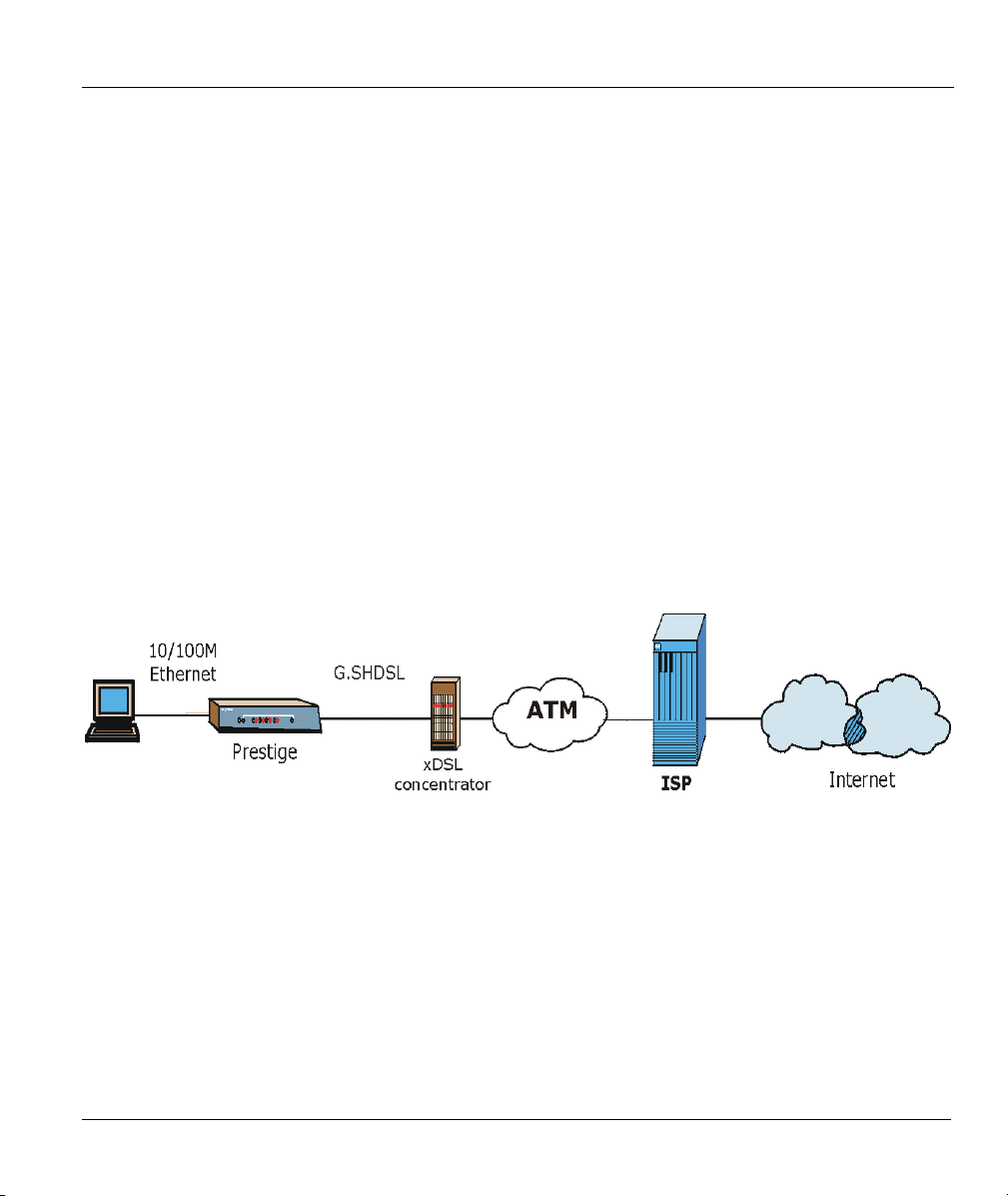
1.2.1 Internet Access
Figure 1-1 Internet Access Application
Your Prestige can act as either of the following:
• An IP LAN modem for a sub-network (Class C or smaller).
• A bridge for multi-computer/MAC bridging (RFC-1483, bridged Ethernet/802.3). For multi-computer
use, the Prestige must connect with a switch or hub.
Getting to Know Your G.SHDSL Bridge 1-3
Page 22
P782M G.SHDSL Bridge
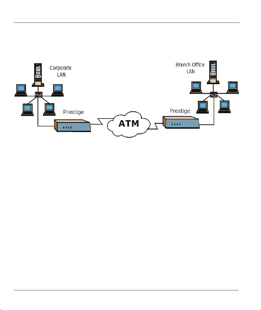
1.2.2 LAN-to-LAN Application
You can use the Prestige to connect two geographically dispersed networks over the DSL line. For multicomputer use, the Prestige must connect with a switch or hub. A typical LAN-to-LAN application is shown
next.
Figure 1-2 LAN-to-LAN Application
1-4 Getting to Know Your G.SHDSL Bridge
Page 23
P782M G.SHDSL Bridge
Chapter 2
Hardware Installation and Initial Setup
This chapter shows how to make cable connections and set up your xDSL connection using the
SMT.
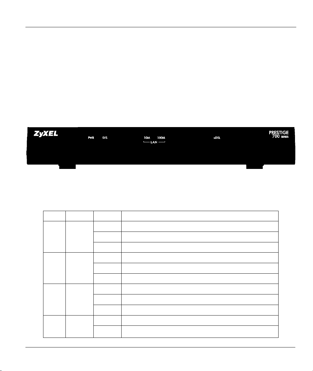
2.1 Front Panel LEDs of the P782
The LEDs on the front panel indicate the operational status of your Prestige
Figure 2-1 Prestige 782 Front Panel
Table 2-1 Front Panel LED Description
LED COLOR
PWR Green
SYS Green
LAN
100M
10M
Hardware Installation and Initial Setup
Orange
Green
STATUS
On The Prestige is receiving power.
Blinking The Prestige is performing a self-test.
Off The Prestige is not receiving power.
On The Prestige is functioning properly.
Blinking The Prestige is rebooting or performing self-diagnostics.
Off The Prestige is not ready or has malfunctioned.
On The Prestige has a successful 100Mb Ethernet connection.
Blinking The Prestige is sending/receiving data.
Off The Prestige does not have 100Mb Ethernet connection.
On The Prestige has a successful 10Mb Ethernet connection. LAN
Blinking The Prestige is sending/receiving data.
DESCRIPTION
Page 24
P782M G.SHDSL Bridge
LED COLOR
xDSL Green
STATUS
Off The Prestige does not have 10Mb Ethernet connection.
On The Prestige has a successful Ethernet connection.
Blinking The Prestige is sending/receiving data.
Off The Prestige is not sending/receiving data.
DESCRIPTION
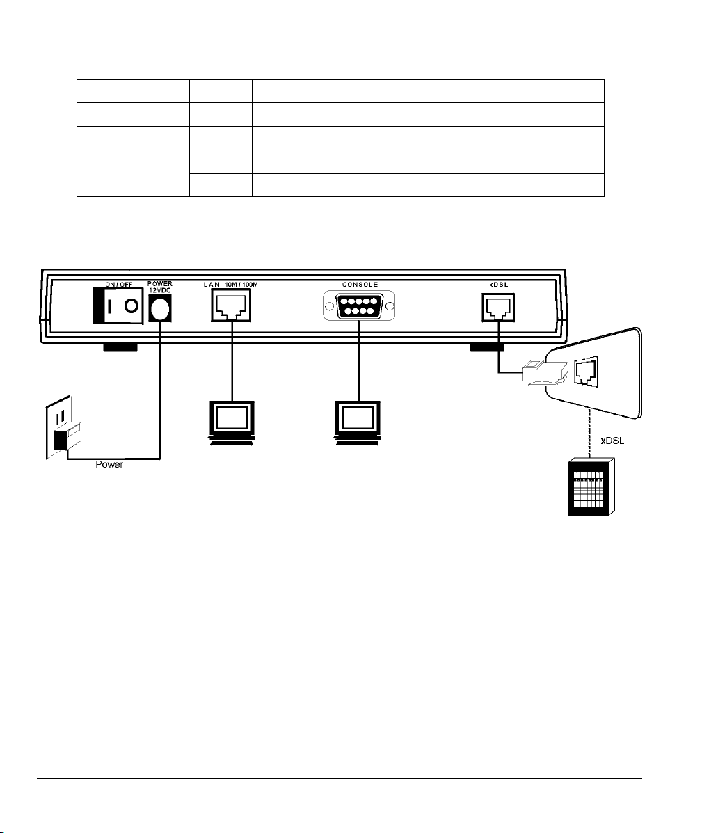
2.2 Rear Panel and Connections of the Prestige 782
The following figure shows the rear panel of your Prestige.
Figure 2-2 Prestige 782 Rear Panel and Connections
2.2.1 xDSL Port
Connect the Prestige (port labeled xDSL) to the telephone jack using the RJ-11 cable (supplied).
2.2.2 Console Port
For the initial configuration of your Prestige, you need to use terminal emulator software on a computer and
connect it to the Prestige through the console port. Connect the 9-pin end of the console cable to the console
port of the Prestige and the other 9-pin end to a serial port (COM1, COM2 or other COM port) of your
computer. You can use an extension RS-232 cable if the enclosed one is too short.
2-2 Hardware Installation and Initial Setup
Page 25

P782M G.SHDSL Bridge
2.2.3 LAN 10/100M Port
Ethernet 10Base-T/100Base-T networks use Shielded Twisted Pair (STP) cable with RJ-45 connectors that
look like a bigger telephone plug with 8 pins. Use the crossover cable to connect your Prestige to a
computer directly or use a straight-through Ethernet cable to connect to an external hub, then connect one
end of the straight-through cable from the hub to the NIC on the computer.
When the Prestige is on and properly connected to a computer or a hub, the
corresponding LAN LED on the front panel turns on.
2.2.4 Power Port
Connect the power adapter to the port labeled POWER on the rear panel of your Prestige.
To avoid damage to the Prestige, make sure you use the correct power adapter.
Refer to the Power Adapter Specification Appendix for this information.
2.3 Additional Installation Requirements
• An Ethernet 10/100Base-T NIC (Network Interface Card).
• Communications software configured as follows:
VT100 terminal emulation
9600 baud
parity set to none, 8 data bits, 1 stop bit
flow control set to none
2.4 Turning On Your Prestige
At this point, you should have connected the xDSL, LAN 10/100M, console and power ports to the
appropriate devices. Make sure the power adapter is plugged into an appropriate power source and the
power switch (located on the back of your Prestige) is “on” (or pressed).
2.5 Configuring Your Prestige For Internet Access
Configure your Prestige for Internet access using:
SMT (System Management Terminal). Access the SMT via:
o LAN or WAN using Telnet
Hardware Installation and Initial Setup
Page 26

P782M G.SHDSL Bridge
o Console port using terminal emulation software
The remainder of this user’s guide shows you how to configure the Prestige for Internet access using SMT
screens. There are also some sections in this guide that also focus on using Telnet to configure the Prestige.
2.5.1 Initial Screen
When you turn on your Prestige, it performs several internal tests as well as line initialization. After the
initialization, the Prestige asks you to press [ENTER] to continue, as shown.
Copyright (c) 1994 - 2002 ZyXEL Communications Corp.
initialize ch =0, ethernet address: 00:a0:c5:01:23:45
Wan Channel init ............ done
Press ENTER to continue...
Figure 2-3 Power-On Display
2.5.2 Entering Password
The login screen appears after you press [ENTER], prompting you to enter the password, as shown next.
For your first login, enter the default password “1234”. As you type the password, the screen displays an
“X” for each character you type.
Please note that if there is no activity for longer than five minutes after you log in, your Prestige will
automatically log you out and will display a blank screen. If you see a blank screen, press [ENTER] to
display the login screen again.
Enter Password : XXXX
Figure 2-4 Login Screen
2-4 Hardware Installation and Initial Setup
Page 27

P782M G.SHDSL Bridge
If, after logging on, there is no activity for longer than 5 minutes, your Prestige
will automatically log you out and display a blank screen. Press [ENTER] to bring
up the login screen again.
2.6 Resetting the Prestige
If you forget your password or cannot access the Prestige, you will need to reload the factory-default
configuration file. Uploading the configuration file replaces the current configuration file with the factorydefault configuration file. This means that you will lose all configurations that you had previously and the
speed of the console port will be reset to the default of 9600bps with 8 data bit, no parity, one stop bit and
flow control set to none. The password will be reset to “1234” and the LAN IP address to 192.168.1.1also.
To obtain the default configuration file, download it from the ZyXEL FTP site, unzip it and save it in a
folder. Turn the Prestige off and then on to begin a session. When you turn on the Prestige again you will
see the initial screen. When you see the message “Press any key to enter Debug Mode within 3 seconds”
press any key to enter debug mode.
To upload the configuration file, do the following:
1. Type atlc after the Enter Debug Mode message.
2. Wait for the Starting XMODEM upload message before activating XMODEM upload on your
terminal.
3. After a successful firmware upload, type atgo to restart the Prestige.
The Prestige is now reinitialized with a default configuration file including the default password of “1234”.
2.6.1 Methods of Restoring Factory-Defaults
You can erase the current configuration and restore factory defaults by uploading the default configuration
file via the console port as described above. See later in this User’s Guide for more information on how to
transfer the configuration file to your Prestige using the SMT menus.
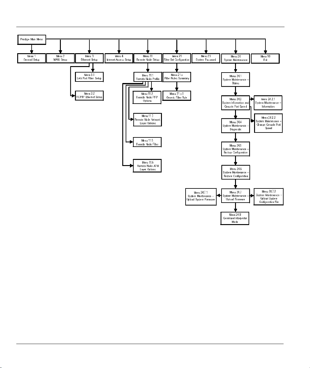
2.7 Prestige 782 SMT Menu Overview
The following figure gives you an overview of the various SMT menu screens of your Prestige.
Hardware Installation and Initial Setup
Page 28
P782M G.SHDSL Bridge
Figure 2-5 Prestige 782 SMT Menu Overview
2.8 Navigating the SMT Interface
The SMT (System Management Terminal) is the interface that you use to configure your Prestige.
Several operations that you should be familiar with before you attempt to modify the configuration are
listed in the table shown next.
2-6 Hardware Installation and Initial Setup
Page 29

P782M G.SHDSL Bridge
Table 2-2 Main Menu Commands
OPERATION KEYSTROKE DESCRIPTION
Move down to
another menu
Move up to a
previous menu
Move to a “hidden”
menu
Move the cursor [ENTER] or
Entering
information
Required fields
N/A fields <N/A> Some of the fields in the SMT will show a <N/A>. This symbol
Save your
configuration
Exit the SMT Type 99, then press
[ENTER] To move forward to a submenu, type in the number of the desired
submenu and press [ENTER].
[ESC] Press [ESC] to move back to the previous menu.
Press [SPACE
BAR] to change No
to
then press
Yes
[ENTER].
[UP]/[DOWN] arrow
keys.
Type in or press
[SPACE BAR], then
press [ENTER].
?>
<
[ENTER] Save your configuration by pressing [ENTER] at the message
[ENTER].
Fields beginning with “Edit” lead to hidden menus and have a
default setting of No. Press [SPACE BAR] once to change No to
, then press [ENTER] to go to the “hidden” menu.
Yes
Within a menu, press [ENTER] to move to the next field. You can
also use the [UP]/[DOWN] arrow keys to move to the previous
and the next field, respectively.
You need to fill in two types of fields. The first requires you to type
in the appropriate information. The second allows you to cycle
through the available choices by pressing [SPACE BAR].
All fields with the symbol <?> must be filled in order to be able to
save the new configuration.
refers to an option that is Not Applicable.
“Press ENTER to confirm or ESC to cancel”. Saving the data on
the screen will take you, in most cases to the previous menu.
Type 99 at the main menu prompt and press [ENTER] to exit the
SMT interface.
After you enter the password, the SMT displays the main menu, as shown next.
Hardware Installation and Initial Setup
Page 30

P782M G.SHDSL Bridge
Prestige 782M Main Menu
Getting Started
1. General Setup
2. WAN Setup
3. LAN Setup
4. Internet Access Setup
Advanced Applications
11. Remote Node Setup
Enter Menu Selection Number:
Copyright (c) 1994 - 2002 ZyXEL Communications Corp.
Advanced Management
21. Filter Set Configuration
23. System Password
24. System Maintenance
99. Exit
Figure 2-6 SMT Main Menu
2.8.1 System Management Terminal Interface Summary
Table 2-3 Main Menu Summary
# MENU TITLE DESCRIPTION
1 General Setup Use this menu to set up your general information.
2 WAN Setup Use this menu to set up your WAN connection.
3 LAN Setup Use this menu to set up your LAN connection.
4 Internet Access Setup A quick and easy way to set up an Internet connection.
11 Remote Node Setup Use this menu to set up the Remote Node for LAN-to-LAN connection,
including Internet connection.
21 Filter Set Configuration Use this menu to set up filters to provide security, etc.
23 System Password Use this menu to change your password.
24 System Maintenance This menu provides system status, diagnostics, software upload, etc.
99 Exit Use this to exit from SMT and return to a blank screen.
2.9 Changing the System Password
Change the default system password by performing the following steps.
Step 1. From the main menu, enter 23 to display Menu 23 — System Password as shown in the
following figure. When the menu appears, type the old system password, for example “1234”,
and press [ENTER].
2-8 Hardware Installation and Initial Setup
Page 31

P782M G.SHDSL Bridge
Menu 23 – System Password
Old Password= ****
New Password= ****
Press ENTER to CONFIRM or ESC to Cancel:
Retype to confirm= ****
Figure 2-7 Menu 23 — System Password
Step 2. Type your new system password (up to 30 characters) and press [ENTER].
Step 3. Re-type your new system password to confirm and press [ENTER].
The screen displays an asterisk “
*” for each character you type.
2.10 General Setup
Menu 1 — General Setup contains administrative and system-related information (shown next). The
System Name field is for identification purposes. However, because some ISPs check this name you should
enter your computer's "Computer Name".
• In Windows 95/98 click Start -> Settings -> Control Panel -> Network. Click the Identification
tab, note the entry for the Computer name field and enter it as the Prestige System Name.
• In Windows 2000 click Start->Settings->Control Panel and then double-click System. Click the
Network Identification tab and then the Properties button. Note the entry for the Computer
name field and enter it as the Prestige System Name.
• In Windows XP, click start -> My Computer -> View system information and then click the
Computer Name tab. Note the entry in the Full computer name field and enter it as the Prestige
System Name.
2.10.1 Procedure To Configure Menu 1
Enter 1 in the main menu to open Menu 1 — General Setup (shown next).
Hardware Installation and Initial Setup
Page 32

P782M G.SHDSL Bridge
Menu 1 - General Setup
System Name= ?
Location=
Contact Person's Name=
Press ENTER to Confirm or ESC to Cancel:
Figure 2-8 Menu 1 — General Setup
Table 2-4 General Setup Menu Fields
FIELD DESCRIPTION EXAMPLE
System Name Choose a descriptive name for identification purposes. This name can be up
to 30 alphanumeric characters long. Spaces are not allowed, but dashes “-”
and underscores "_" are accepted.
Location
(optional)
Contact
Person's
Name
(optional)
Enter the geographic location (up to 31 characters) of your Prestige. MyHouse
Enter the name (up to 30 characters) of the person in charge of this Prestige. JohnDoe
P782
2.11 Setting Up the WAN Link
Use Menu 2 — WAN Setup to configure G.SHDSL settings for your WAN line. Different telephone
companies deploy different types of G.SHDSL service. If you are unsure of any of this information, please
check with your telephone company.
2.11.1 Service Type
Is your Prestige acting as a Server or Client?
1. The Prestige is a server if it is acting as a COE (Central Office Equipment).
2. The Prestige is a client if it is acting as a CPE (Customer Premise Equipment).
2.11.2 Rate Adaption
Both the Prestige and the peer must have the same transmission rate. Rate Adaption allows the Prestige to
auto-detect the peer Transfer Rate (this feature may not be available on all models).
2-10 Hardware Installation and Initial Setup
Page 33

P782M G.SHDSL Bridge
2.11.3 Transfer Rates
The Prestige supports the following symmetrical multi-rate data transmission speeds:
72, 136, 200, 264, 392, 520, 776, 1032, 1160, 1544, 1736, 2056 and 2312 Kbps.
You can increase the capacity of the Internet connection (within certain limitations) without changing your
ISP or buying new equipment.
For back-to-back applications make sure that your Prestige and its peer have the same Transfer Max Rate
and the same Transfer Min Rate. Two (maximum and minimum) transfer rates are used to accommodate
fluctuations in line speed. This is known as Dynamic Bandwidth Allocation.
2.11.4 Standard Mode
If your Prestige is a server, then select the mode that applies to your region: ANSI (American National
Standards Institute) and ETSI (European Telecommunications Standards Institute). If your Prestige is a
client, select the same Standard Mode that the server side selects. ANSI and ETSI create recommendations
and standards for the telecommunications industry.
Press ENTER to Confirm or ESC to Cancel:
Press Space Bar to Toggle.
FIELD DESCRIPTION
Service Type
Rate Adaption
Transfer Max Rate
(2312 Kbps)
Transfer Min Rate
(72 Kbps)
Standard Mode
Menu 2 - WAN Setup
Service Type: Client
Rate Adaption= Enable
Transfer Max Rate(Kbps)= 2312K
Transfer Min Rate(Kbps)= 72K
Standard Mode= ANSI (ANNEX_A)
Figure 2-9 Menu 2 — WAN Setup
Table 2-5 Menu 2 — WAN Setup
Press [SPACE BAR] to select
Press [SPACE BAR] to select
Press [SPACE BAR] to select a
the Transfer Min Rate and press [ENTER] to continue.
Press [SPACE BAR] to select a
Transfer Max Rate and press [ENTER] to continue.
Press [SPACE BAR] to select
[ENTER] to continue. The Client side must match the Server side.
(COE) or
Server
(activate) or
Enable
Transfer Max Rate
Transfer Min Rate
(ANNEX A) or
ANSI
(CPE).
Client
Disable
(deactivate).
greater than or equal to
less than or equal to the
(ANNEX B) and press
ETSI
Hardware Installation and Initial Setup
Page 34

Page 35

P782M G.SHDSL Bridge
Chapter 3
Internet Access
This chapter shows you how to configure the LAN and WAN of your Prestige for Internet access.
3.1 Factory Ethernet Defaults
The Ethernet parameters of the Prestige are preset in the factory with the following values:
♦ IP address of 192.168.1.1 with subnet mask of 255.255.255.0 (24 bits).
3.2 LANs and WANs
A LAN (Local Area Network) is a computer network limited to the immediate area, usually the same
building or floor of a building. A WAN (Wide Area Network), on the other hand, is an outside connection
to another network or the Internet.
3.2.1 LANs, WANs and the Prestige
The actual physical connection determines whether the Prestige ports are LAN or WAN ports. There are
two separate IP networks, one inside, the LAN network; the other outside: the WAN network as shown
next:
Figure 3-1 LAN & WAN IPs
Internet Access 3-1
Page 36

P782M G.SHDSL Bridge
3.3 TCP/IP Parameters
3.3.1 IP Address and Subnet Mask
Like houses on a street that share a common street name, the computers on a LAN share one common
network number.
Where you obtain your network number depends on your particular situation. If the ISP or your network
administrator assigns you a block of registered IP addresses, follow their instructions in selecting the IP
addresses and the subnet mask.
If the ISP did not explicitly give you an IP network number, then most likely you have a single user account
and the ISP will assign you a dynamic IP address when the connection is established. If this is the case, it is
recommended that you select a network number from 192.168.0.0 to 192.168.255.0 (ignoring the trailing
zero) and you must enable the Single User Account feature of the Prestige. The Internet Assigned Number
Authority (IANA) reserved this block of addresses specifically for private use; please do not use any other
number unless you are told otherwise. Let’s say you select 192.168.1.0 as the network number; which
covers 254 individual addresses, from 192.168.1.1 to 192.168.1.254 (zero and 255 are reserved). In other
words, the first three numbers specify the network number while the last number identifies an individual
computer on that network.
The subnet mask specifies the network number portion of an IP address. Your Prestige will compute the
subnet mask automatically based on the IP address that you entered. You don’t need to change the subnet
mask computed by the Prestige unless you are instructed to do otherwise.
3.4 Ethernet Setup
This section describes how to configure the Ethernet using Menu 3 — Ethernet Setup. From the main menu, enter 3 to display menu 3. Settings configured in Menu 3 — Ethernet Setup apply to the LAN side of the modem only.
Menu 3 - Ethernet Setup
1. LAN Port Filter Setup
2. TCP/IP and DHCP Setup
Enter Menu Selection Number:
Figure 3-2 Menu 3 — LAN Setup
3-2 Internet Access
Page 37

P782M G.SHDSL Bridge
3.4.1 LAN Port Filter Setup
This menu allows you to specify filter set(s) that you wish to apply to the Ethernet traffic. You seldom
need to filter Ethernet traffic; however, the filter sets may be useful to block certain packets, reduce traffic
and prevent security breaches.
Menu 3.1 - LAN Port Filter Setup
Input Filter Sets:
device filters=
Output Filter Sets:
device filters=
Press ENTER to Confirm or ESC to Cancel:
Figure 3-3 Menu 3.1 — LAN Port Filter Setup
If you need to define filters, please read the Filter Set Configuration chapter first, then return to this menu
to define the filter sets.
3.5 Protocol Dependent Ethernet Setup
Depending on the protocols for your applications, you need to configure the respective Ethernet Setup, as
outlined next.
For TCP/IP Ethernet setup refer to Internet Access Application.
3.6 TCP/IP Ethernet Setup
This section describes how to configure the Ethernet (or LAN) using Menu 3 — TCP/IP Ethernet Setup.
From the main menu, enter 3 to display the menu shown next.
Menu 3 – TCP/IP Ethernet Setup
Internet Access 3-3
TCP/IP Setup:
IP Address: 192.168.1.1
IP Subnet Mask: 255.255.255.0
Enter Menu Selection Number:
Figure 3-4 Menu 3 —Ethernet Setup
Page 38

P782M G.SHDSL Bridge
Table 3-1 TCP/IP Ethernet Setup Menu Fields
FIELD DESCRIPTION EXAMPLE
TCP/IP Setup
IP Address Enter the (LAN) IP address of your Prestige in dotted decimal
notation
IP Subnet Mask Your Prestige will automatically calculate the subnet mask based on
the IP address that you assign. Unless you are implementing
subnetting, use the subnet mask computed by the Prestige.
When you have completed this menu, press [ENTER] at the prompt “Press ENTER to Confirm…” to save
your configuration, or press [ESC] at any time to cancel.
192.168.1.1
255.255.255.0
3.7 VPI and VCI
Be sure to use the correct Virtual Path Identifier (VPI) and Virtual Channel Identifier (VCI) numbers
supplied by your telephone company. The valid range for the VPI is 0 to 255 and for the VCI is 32 to
65535 (0 to 31 is reserved for local management of ATM traffic). Please see the Appendices for more
information.
3.8 Multiplexing
There are two conventions to identify what protocols the virtual circuit (VC) is carrying. Be sure to use the
multiplexing method required by your ISP.
3.8.1 VC—based Multiplexing
In this case, by prior mutual agreement, each protocol is assigned to a specific virtual circuit, for example,
VC1 carries IP, etc. VC-based multiplexing may be dominant in environments where dynamic creation of
large numbers of ATM VCs is fast and economical.
3.8.2 LLC—based Multiplexing
In this case one VC carries multiple protocols with protocol identifying information being contained in each
packet header. Despite the extra bandwidth and processing overhead, this method may be advantageous if it
is not practical to have a separate VC for each carried protocol, for example, if charging heavily depends on
the number of simultaneous VCs.
3-4 Internet Access
Page 39

P782M G.SHDSL Bridge
3.9 Encapsulation
Be sure to use the encapsulation method required by your ISP. The Prestige supports the following
methods.
3.9.1 PPP
Please refer to RFC 2364 for more information on PPP over ATM Adaptation Layer 5 (AAL5). Refer to
RFC 1661 for more information on PPP.
3.9.2 RFC 1483
RFC 1483 describes two methods for Multiprotocol Encapsulation over ATM Adaptation Layer 5 (AAL5).
The first method allows multiplexing of multiple protocols over a single ATM virtual circuit (LLC-based
multiplexing) and the second method assumes that each protocol is carried over a separate ATM virtual
circuit (VC-based multiplexing). Please refer to the RFC for more detailed information.
3.10 IP Address Assignment
A static IP is a fixed IP that your ISP gives you. A dynamic IP is not fixed; the ISP assigns you a different
one each time.
3.11 Internet Access Configuration
Menu 4 allows you to enter your Internet Access information in one screen. Menu 4 is actually a simplified
setup for one of the remote nodes that you can access in menu 11. Before you configure your Prestige for
Internet access, you need to collect your Internet account information from your ISP and telephone
company.
Use the following table to record your Internet Account Information. Note that if you are using PPP or
encapsulation the only ISP information you need is a login name and password. If you are using RFC 1483,
you do not need a login name or password.
Table 3-2 Internet Account Information
FIELD DESCRIPTION YOUR INFO
ISP’s Name Name of your ISP (optional).
Encapsulation
Multiplexing
Internet Access 3-5
or
PPP
RFC 1483
LLC-based
given, use the default.
.
or
VC-based
. If this information is not
Page 40

P782M G.SHDSL Bridge
FIELD DESCRIPTION YOUR INFO
VPI Enter your Virtual Path Identifier here.
VCI Enter your Virtual Channel Identifier here.
My Login Enter the login name assigned by your ISP (for PPP
only).
My Password Enter the password associated with your ISP assigned
My Login (for PPP only).
3.11.1 Peak Cell Rate (PCR)
Peak Cell Rate (PCR) is the maximum rate at which the sender can send cells. This parameter may be lower
(but not higher) than the maximum line speed. 1 ATM cell is 53 bytes (424 bits), so a maximum speed of
832 Kbps gives a maximum PCR of 1962 cells/sec. This rate is not guaranteed because it is dependent on
the line speed.
If the PCR is set to the default of “0”, the system will assign a maximum value
that correlates to your upstream line rate.
From the main menu, enter 4 to display Menu 4 — Internet Access Setup, as shown next.
Menu 4 - Internet Access Setup
ISP's Name= Change Me
Encapsulation= RFC 1483
Multiplexing= LLC-based
VPI #= 0
VCI #= 33
Peak Cell Rate (PCR)= 0
My Login= N/A
My Password= N/A
Press ENTER to confirm or ESC to cancel:
Figure 3-5 Internet Access Setup
The following table contains instructions on how to configure your Prestige for Internet access.
3-6 Internet Access
Page 41

P782M G.SHDSL Bridge
Table 3-3 Internet Access Setup Menu Fields
FIELD DESCRIPTION EXAMPLE
ISP’s Name Enter the name of your Internet Service Provider. This
information is for identification purposes only.
Encapsulation
Multiplexing
VPI # Enter the Virtual Path Identifier (VPI) that the telephone
VCI # Enter the Virtual Channel Identifier (VCI) that the telephone
Peak Cell Rate
(cell/sec)
My Login Enter the login name that your ISP gives you. N/A
My Password Enter the password associated with the login name above. N/A
When you have completed this menu, press [ENTER] at the prompt “Press ENTER to Confirm…” to save
your configuration, or press [
Press [SPACE BAR] to select the method of encapsulation
used by your ISP. Choices are
SPACE BAR] to select the method of multiplexing
Press [
used by your ISP. Choices are
company gives you.
company gives you.
This is the maximum rate at which the sender can send cells.
Type the PCR.
PPP or RFC 1483
VC-based
or
.
LLC-based
.
ESC] at any time to cancel.
Change Me
RFC 1483
LLC-based
0
33
0
If all your settings are correct your Prestige should connect automatically to the Internet. If the connection
fails, note the error message that you receive on the screen and take the appropriate troubleshooting steps.
Internet Access 3-7
Page 42

Page 43

P782M G.SHDSL Bridge
Chapter 4
Remote Node Configuration
This chapter covers the parameters that are protocol-independent. The protocol-dependent
configurations (TCP/IP and Bridging) are covered in the next chapters.
4.1 Remote Node Setup
A remote node is required for placing calls to a remote gateway. A remote node represents both the remote
gateway and the network behind it across a WAN connection. When you use menu 4 to set up Internet
access, you are configuring one of the remote nodes.
This section describes the protocol-independent parameters for a remote node.
4.1.1 Remote Node Profile
To configure a remote node, follow these steps:
Step 1. From the main menu, enter 11 to display Menu 11 — Remote Node Setup.
Step 2. When menu 11 appears, as shown in the following figure, type the number of the remote node
that you want to configure.
Remote Node Configuration 4-1
Page 44

P782M G.SHDSL Bridge
1. ChangeMe (ISP)
2. ________
3. ________
4. ________
5. ________
6. ________
7. ________
8. ________
9. ________
10. ________
11. ________
12. ________
Enter Node # to Edit:
Menu 11 - Remote Node Setup
Figure 4-1 Menu 11 — Remote Node Setup
4.1.2 Encapsulation and Multiplexing Scenarios
For Internet access you should use the encapsulation and multiplexing methods used by your ISP. For
LAN-to-LAN applications, e.g., branch office and corporate headquarters, prior agreement on methods is
necessary because encapsulation and multiplexing cannot be automatically determined. Which methods to
use depends on how many VCs you have and how many different network protocols you need. The extra
overhead that ENET ENCAP encapsulation entail makes them a poor choice in a LAN-to-LAN application.
Here are some examples of more suitable combinations in such an application.
Scenario 1. One VC, Multiple Protocols
PPP (RFC-2364) encapsulation with VC-based multiplexing is the best combination because no extra
protocol identifying headers are needed. The PPP protocol already contains this information.
Scenario 2. One VC, One Protocol (IP)
Selecting RFC 1483 encapsulation with VC-based multiplexing requires the least amount of overhead (0
octets). However, if there is a potential need for multiple protocol support in the future, it may be safer to
select PPP encapsulation instead of RFC-1483, so you do not need to reconfigure either computer later.
Scenario 3. Multiple VCs
If you have an equal number (or more) of VCs than the number of protocols, then select RFC 1483
encapsulation and VC-based multiplexing.
4-2 Remote Node Configuration
Page 45

P782M G.SHDSL Bridge
Rem Node Name= Change Me
Active= Yes
Encapsulation= RFC 1483
Multiplexing= LLC-based
Incoming:
Rem Login= N/A
Rem Password= N/A
Outgoing:
My Login= N/A
My Password= N/A
Authen= N/A
Menu 11.1 - Remote Node Profile
Press ENTER to Confirm or ESC to Cancel:
Edit PPP Options= N/A
Edit Bridge= No
Edit ATM Options= No
Session Options:
Edit Filter Sets= No
Figure 4-2 Menu 11.1 — Remote Node Profile
In Menu 11.1 — Remote Node Profile, fill in the fields as described in the following table.
Table 4-1 Remote Node Profile Menu Fields
FIELD DESCRIPTION EXAMPLE
Rem Node Name Type a unique, descriptive name of up to eight
characters for this node.
Active
Press [SPACE BAR] and then [ENTER] to select
activate or
to deactivate this node. Inactive nodes
No
are displayed with a minus sign “–“ in SMT menu 11.
refers to RFC-2364 (PPP Encapsulation over ATM
Encapsulation
PPP
Adaptation Layer 5).
If you select
RFC 1483
over ATM Adaptation Layer 5) then
Password, My Login, My Password
Options
fields are not applicable (
(Multiprotocol Encapsulation
Rem Login, Rem
and
Edit PPP
).
N/A
Multiplexing Press [SPACE BAR] and then [ENTER] to select the
method of multiplexing that your ISP uses, either
Incoming:
Rem Login
or
based
LLC-based
Type the login name that this remote node will use to
call your Prestige. The login name and the
Password
will be used to authenticate this node.
.
Rem
Yes
VC-
to
Change Me
Yes
RFC 1483
LLC-based
Remote Node Configuration 4-3
Page 46

P782M G.SHDSL Bridge
FIELD DESCRIPTION EXAMPLE
Rem Password Type the password used when this remote node calls
your Prestige.
Outgoing:
My Login
My Password Type the password assigned by your ISP when the
Authen
Edit PPP Options
Edit Bridge
Edit ATM Options
Session Options:
Edit Filter Sets
When you have completed this menu, press [ENTER] at the prompt “Press [ENTER] to confirm or [ESC]
to cancel” to save your configuration or press [ESC] to cancel and go back to the previous screen.
Type the login name assigned by your ISP when the
Prestige calls this remote node.
Prestige calls this remote node.
This field sets the authentication protocol used for
outgoing calls. Options for this field are:
CHAP/PAP
PAP
CHAP
Authentication Protocol) only.
PAP
only.
To edit the
Use [SPACE BAR] to select
This will take you to
Options.
options, see the section Editing PPP Options.
Press [SPACE BAR] to select
to display
Options
Press [SPACE BAR] to select
to display
Options
Use [SPACE BAR] to choose
to open menu 11.5 to edit the filter sets. See the
Remote Node Filter section for more details.
— Your Prestige will accept either
when requested by this remote node.
— accept
— accept PAP (Password Authentication Protocol)
options, move the cursor to this field.
PPP
For more information on configuring PPP
Menu 11.3 — Remote Node Network Layer
.
Menu 11.6 — Remote Node ATM Layer
.
(Challenge Handshake
CHAP
and press [ENTER].
Yes
Menu 11.2 — Remote Node PPP
and press [ENTER]
Yes
and press [ENTER]
Yes
and press [ENTER]
Yes
CHAP
or
Yes
CHAP/PAP
No
No
No
(default)
4.1.3 Outgoing Authentication Protocol
For obvious reasons, you should employ the strongest authentication protocol possible. However, some
vendors’ implementation includes specific authentication protocol in the user profile. It will disconnect if
4-4 Remote Node Configuration
Page 47

P782M G.SHDSL Bridge
the negotiated protocol is different from that in the user profile, even when the negotiated protocol is
stronger than specified. If the peer disconnects right after a successful authentication, make sure that you
specify the correct authentication protocol when connecting to such an implementation.
4.1.4 Editing PPP Options
To edit the remote node PPP options, move the cursor to the Edit PPP Options field in Menu 11.1 —
Remote Node Profile, use [SPACE BAR] to select Yes and then press [ENTER] to open menu 11.2, as
shown next.
Compression= No
Press Space Bar to Toggle.
Menu 11.2 - Remote Node PPP Options
Encapsulation= Standard PPP
Press ENTER to Confirm or ESC to Cancel:
Figure 4-3 Menu 11.2 — Remote Node PPP Options
The following table describes the menu 11.2 and how to configure the PPP options.
Table 4-2 Remote Node PPP Options Menu Fields
FIELD DESCRIPTION OPTIONS
Select
Encapsulation
Compression
When you have completed this menu, press [ENTER] at the prompt “Press [ENTER] to confirm or [ESC] to
cancel” to save your configuration or press [ESC] to cancel and go back to the previous screen.
Standard PPP
the node is a Cisco computer.
Turn on/off Stac Compression. The default is No.
. Select
CISCO PPP
only if
Standard PPP
CISCO PPP
Yes/No
4.2 Remote Node Setup
For the TCP/IP parameters, perform the following steps to edit Menu 11.3 — Remote Node Network
Layer Options as shown next.
Remote Node Configuration 4-5
Page 48

P782M G.SHDSL Bridge
Step 1. In menu 11.1, make sure the Edit Bridge field is set to Yes and then press [ENTER] to display
Menu 11.3 — Remote Node Network Layer Options (shown next).
Ethernet Addr Timeout(min)= 0
Menu 11.3 - Remote Node Network Layer Options
Enter here to CONFIRM or ESC to CANCEL:
Figure 4-4 Remote Node Network Layer Options
The next table shows you how to configure remote node network layer options.
Table 4-3 TCP/IP-related Fields in Menu 11.1 — Remote Node Profile
FIELD DESCRIPTION EXAMPLE
Ethernet Addr
Timeout
(min.)
Type the time (in minutes) for the Prestige to retain the Ethernet
Address information in its internal tables while the line is down. If this
information is retained, your Prestige will not have to recompile the
tables when the line comes back up.
10
When you have completed this menu, press [ENTER] at the prompt “Press [ENTER] to confirm or
[ESC] to cancel” to save your configuration or press [ESC] to cancel and go back to the previous screen.
4.3 Remote Node Filter
In menu 11.1, make sure the Edit Filter Sets field is set to Yes and then press [ENTER] to display Menu
11.5 — Remote Node Filter (shown next).
Input Filter Sets:
device filters=
Output Filter Sets:
device filters=
Enter here to CONFIRM or ESC to CANCEL:
Figure 4-5 Menu 11.5 — Remote Node Filter
4-6 Remote Node Configuration
Menu 11.5 - Remote Node Filter
Page 49

P782M G.SHDSL Bridge
Use Menu 11.5 — Remote Node Filter to specify the filter set(s) to apply to the incoming and outgoing
traffic between this remote node and the Prestige and also to prevent certain packets from triggering calls.
You can specify up to 4 filter sets separated by comma, e.g., 1, 5, 9, 12, in each filter field.
Remote Node Configuration 4-7
Page 50

Page 51

P782M G.SHDSL Bridge
Chapter 5
Remote Node TCP/IP Configuration
This chapter shows a sample LAN-to-LAN application and how to configure TCP/IP remote
nodes.
5.1.1 Traffic Shaping
Traffic Shaping is an agreement between the carrier and the subscriber to regulate the average rate and
“burstiness” or fluctuation of data transmission over an ATM network. This agreement helps eliminate
congestion, which is important for transmission of real time data such as audio and video connections.
Peak Cell Rate (PCR) is the maximum rate at which the sender can send cells. This parameter may be lower
(but not higher) than the maximum line speed. 1 ATM cell is 53 bytes (424 bits), so a maximum speed of
832 Kbps gives a maximum PCR of 1962 cells/sec. This rate is not guaranteed because it is dependent on
the line speed.
Sustained Cell Rate (SCR) is the mean cell rate of a bursty, on-off traffic source that can be sent at the peak
rate, and a parameter for burst-type traffic. SCR may not be greater than the PCR; the system default is 0
cells/sec.
Maximum Burst Size (MBS) is the maximum number of cells that can be sent at the PCR. After MBS is
reached, cell rates fall below SCR until cell rate averages to the SCR again. At this time, more cells (up to
the MBS) can be sent at the PCR again.
If the PCR, SCR or MBS is set to the default of “0”, the system will assign a
maximum value that correlates to your upstream line rate.
The following figure illustrates the relationship between PCR, SCR and MBS.
Remote Node TCP/IP Configuration 5-1
Page 52

P782M G.SHDSL Bridge
Figure 5-1 Example of Traffic Shaping
5.2 TCP/IP Configuration
The following sections describe how to configure the TCP/IP parameters of a remote node.
5.2.1 Editing TCP/IP Options
Follow the steps ahead to edit Menu 11.6 — Remote Node ATM Layer Options.
In menu 11.1, make sure the Edit ATM Options field is set to Yes and then press [ENTER] to display
Menu 11.6 — Remote Node ATM Layer Options (shown next).
Only one set of VPI and VCI numbers need be specified for all protocols. The valid range for the VPI is 0
to 255 and for the VCI is 32 to 65535 (1 to 31 is reserved for local management of ATM traffic).
5-2 Remote Node TCP/IP Configuration
Page 53

P782M G.SHDSL Bridge
Menu 11.6 - Remote Node ATM Layer Options
VPI #= 8
VCI #= 38
Peak Cell Rate (cell/sec)= 5500
Sustain Cell Rate (cell/sec)= 0
Maximum Burst Size (cell)= 0
ENTER here to CONFIRM or ESC to CANCEL:
Figure 5-2 Menu 11.6 — Remote Node ATM Layer Options
Refer to Chapter 3 for field descriptions found in the last figure.
The following table contains instructions on how to configure your Prestige for Internet access.
Table 5-1 Fields in Menu 11.6 — Remote Node ATM Layer Options
FIELD DESCRIPTION EXAMPLE
VPI # Enter the Virtual Path Identifier (VPI) that the telephone
company gives you.
VCI # Enter the Virtual Channel Identifier (VCI) that the telephone
company gives you.
Peak Cell Rate (PCR) This is the maximum rate at which the sender can send cells.
Type the PCR.
Sustain Cell Rate
(SCR)= 0
Maximum Burst Size
(MBS)= 0
Sustained Cell Rate is the mean cell rate of a bursty, on-off
traffic source that can be sent at the peak rate, and a
parameter for burst-type traffic. Type the SCR; it must be less
than the PCR.
Refers to the maximum number of cells that can be sent at the
peak rate. Type the MBS. The MBS must be less than 65535.
8
35
0
0
0
When you have completed this menu, press [ENTER] at the prompt “Press ENTER to Confirm…” to save
your configuration, or press [
ESC] at any time to cancel.
Remote Node TCP/IP Configuration 5-3
Page 54

Page 55

P782M G.SHDSL Bridge
Chapter 6
Filter Set Configuration
This chapter shows you how to create and apply filters.
6.1 About Filtering
Your Prestige uses filters to decide whether or not to allow passage of a data packet and/or to make a call.
There are two types of filter applications: data filtering and call filtering. Filters are subdivided into device
filters, which are discussed later.
Data filtering examines the data to determine if the packet should be allowed to pass. Data filters are
divided into incoming and outgoing filters, depending on the direction of the packet relative to a port. Data
filtering can be applied on either the WAN side or the Ethernet side. Call filtering is used to determine if a
packet should be allowed to trigger a call.
Outgoing packets undergo data filtering before they encounter call filtering. Call filters are divided into two
groups, the built-in call filters and user-defined call filters. Your Prestige has built-in call filters that prevent
administrative, for examle, RIP packets from triggering calls. These filters are always enabled and not
accessible to you. Your Prestige applies the built-in filters first and then the user-defined call filters, if
applicable, as illustrated in the figure shown next.
Filter Set Configuration 6-1
Page 56

P782M G.SHDSL Bridge
Outgoing
Packet
Data
Filtering
No
match
Match MatchMatch
Built-in
default
Call Filters
Call Filtering
No
match
User-defined
Call Filters
(if applicable)
No
match
Active Data
Initiate call
if line not up
Send packet
and reset
Idle Timer
Drop
packet
Drop packet
if line not up
Drop packet
if line not up
Or Or
Send packet
but do not reset
Idle Timer
Figure 6-1 Outgoing Packet Filtering Process
The following figure illustrates the logic flow when executing a filter rule.
Send packet
but do not reset
Idle Timer
6-2 Filter Set Configuration
Page 57

P782M G.SHDSL Bridge
Start
Packet
intoFilter
Fetch First
Filter Set
Filter Set
Fetch Next
Filter Set
Yes
Next Filter Set
Available?
No
No
Fetch Next
Filter Rule
Yes
Next filter
Rule
Available?
Check
Next
Rule
Fetch First
Filter Rule
No
Active?
Execute
Filter Rule
Drop
Yes
Yes
Forward
Accept PacketDrop Packet
Figure 6-2 Filter Rule Process
You can apply up to four filter sets to a particular port to block various types of packets. Because each filter
set can have up to six rules, you can have a maximum of 24 rules active for a single port.
Filter Set Configuration 6-3
Page 58

P782M G.SHDSL Bridge
For incoming packets, your Prestige applies data filters only. Packets are processed depending on whether a
match is found. The following sections describe how to configure filter sets.
6.2 Configuring a Filter Set
To configure a filter set, follow the steps shown next.
Step 1. Enter 21 in the main menu to display Menu 21 — Filter Set Configuration
Filter
Set #
-----1
2
3
4
5
6
Comments
-----------------______________
______________
______________
______________
______________
______________
Menu 21 - Filter Set Configuration
Filter
Set #
----- 7
8
9
10
11
12
Enter Filter Set Number to Configure= 0
Edit Comments= N/A
Press ENTER to Confirm or ESC to Cancel:
Comments
-----------------______________
______________
______________
______________
______________
______________
Figure 6-3 Menu 21 — Filter Set Configuration
Step 2. Type the filter set to configure (no. 1 to 12) and press [ENTER]
.
Step 3. Type a descriptive name or comment in the Edit Comments field and press [ENTER].
“
Step 4. Press [ENTER] at the message
Rules Summary (that is, if you selected filter set 1 in menu 21).
Press [ENTER] to confirm…” to display Menu 21.1 — Filter
6-4 Filter Set Configuration
Page 59

P782M G.SHDSL Bridge
# A Type Filter Rules M m n
- - ---- -------------------------------------------- --------- - - 1 N Gen Off=0, Len=0, Mask=, Value= N N N
2 N
3 N
4 N
5 N
6 N
Menu 21.1 - Filter Rules Summary
Enter Filter Rule Number (1-6) to Configure:
Figure 6-4 Menu 21.1 — Filter Rules Summary
6.2.1 Filter Rules Summary Menus
The following tables briefly describe the abbreviations used in menus 21.1 and 21.2.
Table 6-1 Abbreviations Used in the Filter Rules Summary Menu
FIELD DESCRIPTION
# The filter rule number: 1 to 6.
A Active: “Y” means the rule is active. “N” means the rule is inactive.
Type The type of filter rule: “GEN” for Generic
Filter Rules These parameters are displayed here.
M More.
“Y” means there are more rules to check which form a rule chain with the present rule.
An action cannot be taken until the rule chain is complete.
“N” means there are no more rules to check. You can specify an action to be taken for
instance, forward the packet, drop the packet or check the next rule. For the latter, the
next rule is independent of the rule just checked.
m Action Matched.
“F” means to forward the packet immediately and skip checking the remaining rules.
“D” means to drop the packet.
“N“ means to check the next rule.
n Action Not Matched.
“F” means to forward the packet immediately and skip checking the remaining rules.
“D” means to drop the packet.
“N” means to check the next rule.
Filter Set Configuration 6-5
Page 60

P782M G.SHDSL Bridge
p
Table 6-2 Rule Abbreviations Used
FILTER TYPE DESCRIPTION
GEN
Off Offset
Len Length
6.3 Generic Filter Rule
The purpose of generic rules is to allow you to filter non-IP packets. For generic rules, the Prestige treats a
packet as a byte stream as opposed to an IP packet. You specify the portion of the packet to check with the
Offset (from 0) and the Length fields, both in bytes. The Prestige applies the Mask (bit-wise ANDing) to
the data portion before comparing the result against the Value to determine a match. The Mask and Value
are specified in hexadecimal numbers.
Two hexadecimal digits represent a byte, so if the length is 4, the value in either field will take 8 digits, e.g.,
FFFFFFFF.
6.3.1 Example Generic Filter Rule Configuration
Step 1. Type a filter set number in Menu 21 — Filter Set Configuration, (“5” in this example), and
press [ENTER] to display menu 21.5.
Step 2. Type a filter rule number in Menu 21.5 — Filter Rules Summary, (“1” in this example), and
press [ENTER] to display Menu 21.5.1 — Generic Filter Rule (shown next).
Press S
ace Bar to Toggle.
Figure 6-5 Menu 21.5.1
Menu 21.5.1 - Generic Filter Rule
Filter #: 5,1
Filter Type= Generic Filter Rule
Active= No
Offset= 0
Length= 0
Mask= N/A
Value= N/A
More= No Log= None
Action Matched= Check Next Rule
Action Not Matched= Check Next Rule
Press ENTER to Confirm or ESC to Cancel:
Generic Filter Rule
—
The table, shown next, describes the fields in Menu 21.5.1 — Generic Filter Rule.
6-6 Filter Set Configuration
Page 61

P782M G.SHDSL Bridge
Table 6-3 Menu 21.5.1 — Generic Filter Rule Fields
FIELD DESCRIPTION EXAMPLE
Filter # This is the filter set, filter rule coordinates, for instance, 2, 3 refers to the
second filter set and the third rule of that set.
Filter Type This field may not be changed.
Active
Offset Type the starting byte of the data portion in the packet that you want to
Length Type the byte count of the data portion in the packet that you want to
Mask Type the mask (in Hexadecimal) to apply to the data portion before
Value Type the value (in Hexadecimal) to compare with the data portion.
More
Log Select the logging option from the following:
Action
Matched
Action Not
Matched
When you have completed this menu, press [ENTER] at the prompt “Press [ENTER] to confirm or [ESC]
to cancel” to save your configuration or press [ESC] to cancel and go back to the previous screen.
Select
compare. The range for this field is from 0 to 255.
compare. The range for this field is 0 to 8.
comparison.
If
Yes
is taken or else the packet is disposed of according to the action fields.
If
More
N/A
None
Action Matched
Action Not Matched
parameters will be logged.
Both
Select the action for a matching packet. Choices are
Forward
Select the action for a packet not matching the rule. Choices are
Next Rule, Forward
to turn on or No to turn off the filter rule.
Yes
, a matching packet is passed to the next filter rule before an action
is
, then
Yes
.
— No packets will be logged.
— All packets will be logged.
or
Drop
Action Matched
— Only matching packets and rules will be logged.
— Only packets that do not match the rule
.
or
Drop
.
and
Action Not Matched
will be
Check Next Rule
Check
,
5,1
Generic Filter
Rule
No
(default)
0
(default)
0
(default)
No
(default)
None
Check Next
Rule
(default)
Check Next
(default)
Rule
Filter Set Configuration 6-7
Page 62

P782M G.SHDSL Bridge
6.4 Filter Configuration Example
Let us look at a sample filter. See the supporting disk for more sample filters.
Step 1. Enter 21 from the main menu to open Menu 21 — Filter Set Configuration.
Step 2. Enter the index of the filter set you want to configure (in this case 3)
Step 3. Enter a descriptive name or comment in the Edit Comments field (in this case, test).
“
Step 4. Press [ENTER] at the message
21.3 — Filter Rules Summary.
Step 5. Enter 1 to configure the first filter rule. When you press [ENTER] to confirm, the following
screen appears. Note that there is only one filter rule in this set.
Make the entries in this menu as shown next.
Press [ENTER] to confirm or [ESC] to cancel” to open Menu
.
6-8 Filter Set Configuration
Page 63

P782M G.SHDSL Bridge
Select Yes to make
the rule active.
Menu 21.3.1 – Generic Filter Rule
Filter #: 3,1
Filter Type= Generic Filter Rule
Active= Yes
Offset= 9
Length= 4
Mask= 789abcde
Value= 789abcde
More= No Log= None
Action Matched= Drop
Action Not Matched= Forward
Press ENTER to Confirm or ESC to Cancel:
.This is the first byte of the data portion in
the packet that you want to compare.
There are no more rules to check in this filter set.
Figure 6-6 Sample Filter — Menu 21.3.1
This is the length (in bytes) of the data portion
in the packet that you want to compare.
The Mask is applied to the data portion before
comparing the result against the Value to
determine a match. It is specified in
hexadecimal, and it takes two hexadecimal digits
to represent a byte i.e., Length is 4, therefore
there are 8 hex numbers.
Enter the value (in hex) to compare with the data
portion.
This setting logs all packets that match these
rule parameters.
Select Drop here so that the packet will be
dropped if the action is not matched.
Select Forward here so that the packet will be
forwarded if the action is matched.
When you press [ENTER] to confirm, you will see the next screen. Note that there is only one filter rule in
this set.
Filter Set Configuration 6-9
Page 64

P782M G.SHDSL Bridge
f
# A Type Filter Rules M m n
- - ---- --------------------------------------------------------------- - - 1 Y Gen Off=9, Len=4, Mask=789abcde, Value=789abcde N F D
2 N
3 N
4 N
5 N
6 N
Enter Filter Rule Number (1-6) to Configure: 1
This shows what you configured in
the previous menu.
Menu 21.3 - Filter Rules Summary
M = N means an action can be taken immediately. The
action is to drop the packet (m = D) if the action is
matched and to forward the packet immediately (n = F) i
the action is not matched no matter whether there are
more rules to be checked (there are not in this example).
Figure 6-7 Sample Filter Rules Summary — Menu 21.3
After you have created the filter set, you must apply it.
Step 1. Enter 11, in the main menu, to display menu 11.
Step 2. Enter the remote node number to edit.
Step 3. Make sure the Edit Filter Sets field is set to Yes and press [ENTER] to display menu 11.5.
Step 4. Apply the example filter set (eg. filter set 3) in this menu as shown in the next section.
6.5 Applying Filters
This section shows you where to apply the filters after you design them. Filter rules may be configured in
menu 21 to filter traffic.
FILTER SETS DESCRIPTION
Input Filter Sets: Apply filters for incoming traffic. You may apply device filter rules.
See earlier in this chapter for information on filters.
Output Filter Sets: Apply filters for traffic leaving the Prestige. You may apply device
filters. See earlier in this section for information on f filters.
6-10 Filter Set Configuration
Page 65

P782M G.SHDSL Bridge
6.5.1 Ethernet Traffic
6.5.2 Ethernet Traffic
You seldom need to filter Ethernet traffic; however, the filter sets may be useful to block certain packets,
reduce traffic and prevent security breaches. Go to menu 3.1 (shown next) and type the number(s) of the
filter set(s) that you want to apply as appropriate. You can choose up to four filter sets (from twelve) by
typing their numbers separated by commas, for example, 3, 4, 6, 11.
Menu 3.1 – LAN Port Filter Setup
Input Filter Sets:
device filters=
Output Filter Sets:
device filters=
Press ENTER to Confirm or ESC to Cancel:
Figure 6-8 Filtering Ethernet Traffic
6.5.3 Remote Node Filters
Go to menu 11.5 (shown next) and type the number(s) of the filter set(s) as appropriate. You can cascade up
to four filter sets by type ing their numbers separated by commas.
Menu 11.5 – Remote Node Filter
Input Filter Sets:
device filters=
Output Filter Sets:
device filters=
Figure 6-9 Filtering Remote Node Traffic
Filter Set Configuration 6-11
Page 66

Page 67

P782M G.SHDSL Bridge
Chapter 7
System Information and Diagnosis
This chapter covers the information and diagnostic tools in SMT menus 24.1 to 24.4 and 24.8.
These tools include updates on system status, port status and upgrades for the system software. This chapter
describes how to use these tools in detail.
Enter 24 in the main menu to display Menu 24
—
System Maintenance, shown next.
Menu 24 - System Maintenance
1. System Status
2. System Information and Console Port Speed
4. Diagnostic
5. Backup Configuration
6. Restore Configuration
7. Upload Firmware
8. Command Interpreter Mode
Enter Menu Selection Number:
Figure 7-1 Menu 24 — System Maintenance
7.1 System Status
System Status displays status and statistics of the Prestige. Menu 24.1 — System Maintenance — Status
is meant for diagnostic purposes.
From the main menu, enter 24 to display Menu 24 — System Maintenance. Enter 1 to display Menu 24.1
— System Maintenance — Status, shown next.
System Information and Diagnosis 7-1
Page 68

P782M G.SHDSL Bridge
Node-Lnk Status TxPkts RxPkts Errors Tx B/s Rx B/s Up Time
1-1483 N/A 0 0 0 0 0 0:00:00
2 N/A 0 0 0 0 0 0:00:00
3 N/A 0 0 0 0 0 0:00:00
4 N/A 0 0 0 0 0 0:00:00
5 N/A 0 0 0 0 0 0:00:00
6 N/A 0 0 0 0 0 0:00:00
7 N/A 0 0 0 0 0 0:00:00
8 N/A 0 0 0 0 0 0:00:00
9 N/A 0 0 0 0 0 0:00:00
10 N/A 0 0 0 0 0 0:00:00
11 N/A 0 0 0 0 0 0:00:00
12 N/A 0 0 0 0 0 0:00:00
Ethernet: WAN:
Status: Down Tx Pkts: 0 Line Status: Down
Collisions: 0 Rx Pkts: 197 Transfer Rate: 0 kbps
CPU Load = 3.71%
Press Command:
COMMANDS: 1-Reset Counters ESC-Exit
Menu 24.1 - System Maintenance - Status
Figure 7-2 Menu 24.1 — System Maintenance — Status
The following table describes the fields present in Menu 24.1 — System Maintenance — Status.
Table 7-1 System Maintenance
FIELD DESCRIPTION
Node-Lnk This is the node index number and link type. Link types are: PPP, ENET, 1483.
Status Shows the status of the remote node.
TxPkts The number of transmitted packets to this remote node.
RxPkts The number of received packets from this remote node.
Errors The number of error packets on this connection.
Tx B/s Shows the transmission rate in bytes per second.
Rx B/s Shows the receiving rate in bytes per second.
Up Time Time this channel has been connected to the current remote node.
Ethernet Shows statistics for the LAN.
Status Shows the current status of the LAN.
Collisions Number of collisions.
CPU Load Specifies the percentage of CPU utilization.
Status Menu Fields
—
7-2 System Information and Diagnosis
Page 69

P782M G.SHDSL Bridge
FIELD DESCRIPTION
WAN Shows statistics for the WAN.
Tx Pkts The number of transmitted packets to the LAN.
Rx Pkts The number of received packets from the LAN.
Line Status Shows the current status of the xDSL line which can be Up or Down.
Transfer
Commands
Shows the transfer rate of the Prestige.
Rate
1 Enter 1 to reset the counters
ESC Press [ESC] to display the previous screen.
7.2 System Information and Console Port Speed
This section describes your system and allows you to choose different console port speeds. To display the
System Information and Console Port Speed menu, follow the steps shown next.
Step 1. Enter 24 to display Menu 24 — System Maintenance.
Step 2. Enter 2 to display Menu 24.2 — System Information and Console Port Speed.
Step 3. From this menu you have two choices as shown in the next figure:
Menu 24.2 - System Information and Console Port Speed
1. System Information
Please enter selection:
2. Console Port Speed
Figure 7-3 Menu 24.2 — System Information and Console Port Speed
7.2.1 System Information
Enter 1 in menu 24.2 to display the screen shown next.
System Information and Diagnosis 7-3
Page 70

P782M G.SHDSL Bridge
Menu 24.2.1 – System Maintenance – Information
Name:
ZyNOS F/W Version: V2.50(BM.0)b2 | 1/30/2002
xDSL Firmware Version: R.1.5
LAN
Ethernet Address: 00:a0:c5:01:23:45
IP Address: 192.168.1.1
IP Mask: 255.255.255.0
Press ESC or RETURN to Exit:
Figure 7-4 Menu 24.2.1 — System Maintenance — Information
Table 7-2 Fields in System Maintenance
FIELD DESCRIPTION
Name Displays the system name of your Prestige. This information can be changed in
Menu 1 — General Setup
ZyNOS F/W Version Refers to the ZyNOS (ZyXEL Network Operating System) system firmware
version. ZyNOS is a registered trademark of ZyXEL Communications
Corporation.
xDSL Firmware
Displays the xDSL firmware version.
Version
LAN
Ethernet Address Refers to the Ethernet MAC (Media Access Control) of your Prestige.
IP Address This is the IP address of the Prestige in dotted decimal notation.
IP Mask This shows the subnet mask of the Prestige.
.
7.2.2 Console Port Speed
You can set up different port speeds for the console port through Menu 24.2.2 — System Maintenance —
Console Port Speed. Your Prestige supports 9600 (default), 19200, 38400, 57600 and 115200bps. Use
[SPACE BAR] and then [ENTER] to select the desired speed in menu 24.2.2, as shown in the following
figure.
7-4 System Information and Diagnosis
Page 71

P782M G.SHDSL Bridge
Menu 24.2.2 – System Maintenance – Change Console Port Speed
Console Port Speed: 9600
Press Space Bar to Toggle.
Press ENTER to Confirm or ESC to Cancel:
Figure 7-5 Menu 24.2.2 — System Maintenance — Change Console Port Speed
7.3 Diagnostic
The diagnostic facility allows you to test the different aspects of your Prestige to determine if it is working
properly. Menu 24.4 allows you to choose among various types of diagnostic tests to evaluate your system.
Follow the procedure next display menu 24.4.
Step 1. From the main menu, enter 24 to display Menu 24 — System Maintenance.
Step 2. Enter 4 to display Menu 24.4 — System Maintenance — Diagnostic, shown next.
xDSL
1. Reset xDSL
Figure 7-6 Menu 24.4 — System Maintenance — Diagnostic
Menu 24.4 - System Maintenance – Diagnostic
System
21. Reboot System
22. Command Mode
Enter Menu Selection Number:
Host IP Address= N/A
The following table describes the diagnostic tests available in menu 24.4 for and the connections.
Table 7-3 System Maintenance Menu — Diagnostic
FIELD DESCRIPTION
Reset xDSL Type 1 to re-initialize the xDSL link to the telephone company.
Reboot System Type 21 to reboot the Prestige.
Command Mode Type 22 to test and diagnose your Prestige using specified commands.
System Information and Diagnosis 7-5
Page 72

P782M G.SHDSL Bridge
7.4 Command Interpreter Mode
The Command Interpreter (CI) is a part of the main system firmware. The CI provides much of the same
functionality as the SMT, while adding some low-level setup and diagnostic functions. Access can be by
Telnet or by a serial connection to the console port, although some commands are only available with a
serial connection. See the included disk or the zyxel.com web site for more detailed information on CI
commands.
Enter 8 from Menu 24 — System Maintenance. A list of valid commands can be found by typing help or
? at the command prompt. Type “exit” to return to the SMT main menu when finished.
1. System Status
2. System Information and Console Port Speed
4. Diagnostic
5. Backup Configuration
6. Restore Configuration
7. Firmware Update
8. Command Interpreter Mode
Enter Menu Selection Number:
Menu 24 - System Maintenance
Figure 7-7 Command Mode in Menu 24
Copyright (c) 1994 - 2002 ZyXEL Communications Corp.
ras> ?
Valid commands are:
sys exit device ether
wan poe xdsl atm
fpga ip ppp bridge
hdap
emitest>
Figure 7-8 Valid Commands
7-6 System Information and Diagnosis
Page 73

P782M G.SHDSL Bridge
Chapter 8
Firmware and Configuration File
Maintenance
This chapter shows you how to back up and restore your configuration file as well as upload new
firmware and a new configuration file.
8.1 Filename Conventions
The configuration file (often called the romfile or rom-0) contains the factory default settings in the menus
such as password, DHCP Setup, TCP/IP Setup, etc. It arrives from ZyXEL with a “rom” filename
extension. Once you have customized the Prestige's settings, they can be saved back to your computer under
a filename of your choosing.
ZyNOS (ZyXEL Network Operating System sometimes referred to as the “ras” file) is the system firmware
and has a “bin” filename extension. With many FTP and TFTP clients, the filenames are similar to those
seen next.
ftp> put firmware.bin ras
This is a sample FTP session showing the transfer of the computer file " firmware.bin" to the Prestige.
ftp> get rom-0 config.cfg
This is a sample FTP session saving the current configuration to the computer file “config.cfg”.
If your (T)FTP client does not allow you to have a destination filename different than the source, you will
need to rename them as the Prestige only recognizes “rom-0” and “ras”. Be sure you keep unaltered copies
of both files for later use.
The following table is a summary. Please note that the internal filename refers to the filename on the
Prestige and the external filename refers to the filename not
network or FTP site and so the name (but not the extension) may vary. After uploading new firmware, see
the ZyNOS F/W Version field in Menu 24.2.1 — System Maintenance — Information to confirm that
you have uploaded the correct firmware version. The AT command is the command you enter after you
press “y” when prompted in the SMT menu to go into debug mode.
Firmware and Configuration File Maintenance 8-1
on the Prestige, that is, on your computer, local
Page 74

P782M G.SHDSL Bridge
Table 8-1 Filename Conventions
FILE TYPE INTERNAL NAME EXTERNAL NAME DESCRIPTION
Configuration
File
Firmware Ras This is the generic name for the
Rom-0 This is the configuration filename on
the Prestige. Uploading the rom-0 file
replaces the entire ROM file system,
including your Prestige configurations,
system-related data (including the
default password), the error log and
the trace log.
ZyNOS firmware on the Prestige.
*.rom
*.bin
8.2 Backup Configuration
The Prestige displays different messages explaining different ways to backup,
restore and upload files in menus 24.5, 24.6, 24. 7.1 and 24.7.2; depending on
whether you use the console port or Telnet.
Option 5 from Menu 24 — System Maintenance allows you to backup the current Prestige configuration
to your computer. Backup is highly recommended once your Prestige is functioning properly. FTP is the
preferred methods for backing up your current configuration to your computer since they are faster. You
can also perform backup and restore using menu 24 through the console port. Any serial communications
program should work fine; however, you must use Xmodem protocol to perform the download/upload and
you don’t have to rename the files.
Please note that terms “download” and “upload” are relative to the computer. Download means to transfer
from the Prestige to the computer, while upload means from your computer to the Prestige.
8-2 Firmware and Configuration File Maintenance
Page 75

P782M G.SHDSL Bridge
8.2.1 Backup Configuration
Follow the instructions as shown in the next screen.
Menu 24.5 - System Maintenance - Backup Configuration
To transfer the configuration file to your workstation, follow the procedure
below:
1. Launch the FTP client on your workstation.
2. Type "open" and the IP address of your system. Then type "root" and
SMT password as requested.
3. Locate the 'rom-0' file.
4. Type 'get rom-0' to back up the current system configuration to
your workstation.
For details on FTP commands, please consult the documentation of your FTP
client program. For details on backup using TFTP (note that you must remain
in this menu to back up using TFTP), please see your system manual.
Press ENTER to Exit:
Figure 8-1 Telnet in Menu 24.5
8.2.2 Using the FTP Command from the Command Line
Step 1. Launch the FTP client on your computer.
Step 2. Enter “open”, followed by a space and the IP address of your Prestige.
Step 3. Press [ENTER] when prompted for a username.
Step 4. Enter your password as requested (the default is “1234”).
Step 5. Enter “bin” to set transfer mode to binary.
Step 6. Use “get” to transfer files from the Prestige to the computer, for example, “get rom-0
config.rom” transfers the configuration file on the Prestige to your computer and renames it
“config.rom”. See earlier in this chapter for more information on filename conventions.
Step 7. Enter “quit” to exit the ftp prompt.
8.2.3 Example of FTP Commands from the Command Line
Firmware and Configuration File Maintenance 8-3
Page 76

P782M G.SHDSL Bridge
331 Enter PASS command
Password:
230 Logged in
ftp> bin
200 Type I OK
ftp> get rom-0 zyxel.rom
200 Port command okay
150 Opening data connection for STOR ras
226 File received OK
ftp: 16384 bytes sent in 1.10Seconds 297.89Kbytes/sec.
ftp> quit
Figure 8-2 FTP Session Example
8.2.4 GUI-based FTP Clients
The following table describes some of the commands that you may see in GUI-based FTP clients.
Table 8-2 General Commands for GUI-based FTP Clients
COMMAND DESCRIPTION
Host Address Enter the address of the host server.
Login Type Anonymous.
This is when a user I.D. and password is automatically supplied to the
server for anonymous access. Anonymous logins will work only if your
ISP or service administrator has enabled this option.
Normal.
The server requires a unique User ID and Password to login.
Transfer Type Transfer files in either ASCII (plain text format) or in binary mode.
Initial Remote Directory Specify the default remote directory (path).
Initial Local Directory Specify the default local directory (path).
TFTP and FTP over WAN will not work when you have an SMT console session
running.
8.2.5 Backup Configuration Using TFTP
The Prestige supports the up/downloading of the firmware and the configuration file using TFTP (Trivial
File Transfer Protocol) over LAN. Although TFTP should work over WAN as well, it is not recommended.
To use TFTP, your computer must have both telnet and TFTP clients. To backup the configuration file,
follow the procedure shown next.
8-4 Firmware and Configuration File Maintenance
Page 77

P782M G.SHDSL Bridge
Step 1. Use telnet from your computer to connect to the Prestige and log in. Because TFTP does not
have any security checks, the Prestige records the IP address of the telnet client and accepts
TFTP requests only from this address.
Step 2. Put the SMT in command interpreter (CI) mode by entering 8 in Menu 24 — System
Maintenance.
Step 3. Enter command “sys stdio 0” to disable the SMT timeout, so the TFTP transfer will not be
interrupted. Enter command “sys stdio 5” to restore the five-minute SMT timeout (default) when
the file transfer is complete.
Step 4. Launch the TFTP client on your computer and connect to the Prestige. Set the transfer mode to
binary before starting data transfer.
Step 5. Use the TFTP client (see the example below) to transfer files between the Prestige and the
computer. The file name for the configuration file is “rom-0” (rom-zero, not capital o).
Note that the telnet connection must be active and the SMT in CI mode before and during the TFTP
transfer. For details on TFTP commands (see following example), please consult the documentation of your
TFTP client program. For UNIX, use “get” to transfer from the Prestige to the computer and “binary” to set
binary transfer mode.
8.2.6 TFTP Command Example
The following is an example TFTP command:
tftp [-i] host get rom-0 config.rom
where “i” specifies binary image transfer mode (use this mode when transferring binary files), “host” is the
Prestige IP address, “get” transfers the file source on the Prestige (rom-0, name of the configuration file on
the Prestige) to the file destination on the computer and renames it config.rom.
8.2.7 GUI—based TFTP Clients
The following table describes some of the fields that you may see in GUI-based TFTP clients.
Table 8-3 General Commands for GUI-based TFTP Clients
COMMAND DESCRIPTION
Host Enter the IP address of the Prestige. 192.168.1.1 is the Prestige’s default IP address
when shipped.
Send/Fetch Use “Send” to upload the file to the Prestige and “Fetch” to back up the file on your
computer.
Local File Enter the path and name of the firmware file (*.bin extension) or configuration file (*.rom
extension) on your computer.
Firmware and Configuration File Maintenance 8-5
Page 78

P782M G.SHDSL Bridge
Remote File This is the filename on the Prestige. The filename for the firmware is “ras” and for the
configuration file, is “rom-0”.
Binary Transfer the file in binary mode.
Abort Stop transfer of the file.
Refer to section 0 to read about configurations that disallow TFTP and FTP over WAN.
8.2.8 Backup Via Console Port
Back up configuration via console port by following the HyperTerminal procedure shown next. Procedures
using other serial communications programs should be similar.
Step 1. Display menu 24.5 and enter “y” at the following screen.
Ready to backup Configuration via Xmodem.
Do you want to continue (y/n):
Figure 8-3 System Maintenance — Backup Configuration
Step 2. The following screen indicates that the Xmodem download has started.
You can enter ctrl-x to terminate operation any time.
Starting XMODEM download...
Figure 8-4 System Maintenance — Starting Xmodem Download Screen
Step 3. Run the HyperTerminal program by clicking Transfer, then Receive File as shown in the
following screen.
8-6 Firmware and Configuration File Maintenance
Page 79

P782M G.SHDSL Bridge
Type a location for storing the
configuration file or click
Browse to look for one.
Choose the Xmodem protocol.
Then click Receive.
Figure 8-5 Backup Configuration Example
Step 4. After a successful backup you will see the following screen. Press any key to return to the SMT
menu.
** Backup Configuration completed. OK.
### Hit any key to continue.###
Figure 8-6 Successful Backup Confirmation Screen
8.3 Restore Configuration
This section shows you how to restore a previously saved configuration. Note that this function erases the
current configuration before restoring a previous back up configuration; please do not attempt to restore
unless you have a backup configuration file stored on disk.
FTP is the preferred method for restoring your current computer configuration to your Prestige since FTP is
faster. Please note that you must wait for the system to automatically restart after the file transfer is
complete.
Firmware and Configuration File Maintenance 8-7
Page 80

P782M G.SHDSL Bridge
WARNING!
DO NOT INTERUPT THE FILE TRANSFER PROCESS AS THIS MAY
PERMANENTLY DAMAGE YOUR PRESTIGE. WHEN THE RESTORE
CONFIGURATION PROCESS IS COMPLETE, THE PRESTIGE WILL
AUTOMATICALLY RESTART.
8.3.1 Restore Using FTP
For details about backup using (T)FTP please refer to earlier sections on FTP and TFTP file upload in this
chapter.
Menu 24.6 -- System Maintenance - Restore Configuration
To transfer the firmware and configuration file to your workstation, follow the procedure
below:
1. Launch the FTP client on your workstation.
2. Type "open" and the IP address of your system. Then type "root" and
SMT password as requested.
3. Type "put backupfilename rom-0" where backupfilename is the name of
your backup configuration file on your workstation and rom-0 is the
remote file name on the system. This restores the configuration to
your system.
4. The system reboots automatically after a successful file transfer
For details on FTP commands, please consult the documentation of your FTP
client program. For details on backup using TFTP (note that you must remain
in this menu to back up using TFTP), please see your system manual.
Press ENTER to Exit:
Figure 8-7 Telnet into Menu 24.6
Step 1. Launch the FTP client on your computer.
Step 2. Enter “open”, followed by a space and the IP address of your Prestige.
Step 3. Press [ENTER] when prompted for a username.
Step 4. Enter your password as requested (the default is “1234”).
Step 5. Enter “bin” to set transfer mode to binary.
Step 6. Find the “rom” file (on your computer) that you want to restore to your Prestige.
8-8 Firmware and Configuration File Maintenance
Page 81

P782M G.SHDSL Bridge
Step 7. Use “put” to transfer files from the Prestige to the computer, for example, “put config.rom rom-
0” transfers the configuration file “config.rom” on your computer to the Prestige. See earlier in
this chapter for more information on filename conventions.
Step 8. Enter “quit” to exit the ftp prompt. The Prestige will automatically restart after a successful
restore process.
8.3.2 Restore Using FTP Session Example
ftp> put config.rom rom-0
200 Port command okay
150 Opening data connection for STOR rom-0
226 File received OK
221 Goodbye for writing flash
ftp: 16384 bytes sent in 0.06Seconds 273.07Kbytes/sec.
ftp>quit
Figure 8-8 Restore Using FTP Session Example
Refer to section 0 to read about configurations that disallow TFTP and FTP over WAN.
8.3.3 Restore Via Console Port
Restore configuration via console port by following the HyperTerminal procedure shown next. Procedures
using other serial communications programs should be similar.
Step 1. Display menu 24.6 and enter “y” at the following screen.
Ready to restore Configuration via Xmodem.
Do you want to continue (y/n):
Figure 8-9 System Maintenance — Restore Configuration
Step 2. The following screen indicates that the Xmodem download has started.
Starting XMODEM download (CRC mode) ...
CCCCCCCCC
Figure 8-10 System Maintenance — Starting Xmodem Download Screen
Step 3. Run the HyperTerminal program by clicking Transfer, then Send File as shown in the
following screen.
Firmware and Configuration File Maintenance 8-9
Page 82

P782M G.SHDSL Bridge
Type the configuration file’s
location, or click Browse to
search for it.
Choose the Xmodem protocol.
Then click Send.
Figure 8-11 Restore Configuration Example
Step 4. After a successful restoration you will see the following screen. Press any key to restart the
Prestige and return to the SMT menu.
Save to ROM
Hit any key to start system reboot.
Figure 8-12 Successful Restoration Confirmation Screen
8.4 Uploading Firmware and Configuration Files
This section shows you how to upload firmware and configuration files. You can upload configuration files
by following the procedure in the previous Restore Configuration section or by following the instructions in
Menu 24.7.2 — System Maintenance — Upload System Configuration File (for console port).
WARNING!
DO NOT INTERUPT THE FILE TRANSFER PROCESS AS THIS MAY
PERMANENTLY DAMAGE YOUR PRESTIGE.
8.4.1 Firmware File Upload
FTP is the preferred method for uploading the firmware and configuration. To use this feature, your
computer must have an FTP client.
When you telnet into the Prestige, you will see the following screens for uploading firmware and the
configuration file using FTP.
8-10 Firmware and Configuration File Maintenance
Page 83

P782M G.SHDSL Bridge
Menu 24.7.1 - System Maintenance - Upload System Firmware
To upload the system firmware, follow the procedure below:
1. Launch the FTP client on your workstation.
2. Type "open" and the IP address of your system. Then type "root" and
SMT password as requested.
3. Type "put firmwarefilename ras" where "firmwarefilename" is the name
of your firmware upgrade file on your workstation and "ras" is the
remote file name on the system.
4. The system reboots automatically after a successful firmware upload.
For details on FTP commands, please consult the documentation of your FTP
client program. For details on uploading system firmware using TFTP (note
that you must remain on this menu to upload system firmware using TFTP),
please see your manual.
Press ENTER to Exit:
Figure 8-13 Telnet Into Menu 24.7.1 — Upload System Firmware
8.4.2 Configuration File Upload
You see the following screen when you telnet into menu 24.7.2.
Menu 24.7.2 - System Maintenance - Upload System Configuration File
To upload the system configuration file, follow the procedure below:
1. Launch the FTP client on your workstation.
2. Type "open" and the IP address of your system. Then type "root" and
SMT password as requested.
3. Type "put configurationfilename rom-0" where "configurationfilename"
is the name of your system configuration file on your workstation, which
will be transferred to the "rom-0" file on the system.
4. The system reboots automatically after the upload system configuration
file process is complete.
For details on FTP commands, please consult the documentation of your FTP
client program. For details on uploading system firmware using TFTP (note
that you must remain on this menu to upload system firmware using TFTP),
please see your manual.
Press ENTER to Exit:
Figure 8-14 Telnet Into Menu 24.7.2 — System Maintenance
Firmware and Configuration File Maintenance 8-11
Page 84

P782M G.SHDSL Bridge
To upload the firmware and the configuration file, follow these examples
8.4.3 FTP File Upload Command from the DOS Prompt Example
Step 1. Launch the FTP client on your computer.
Step 2. Enter “open”, followed by a space and the IP address of your Prestige.
Step 3. Press [ENTER] when prompted for a username.
Step 4. Enter your password as requested (the default is “1234”).
Step 5. Enter “bin” to set transfer mode to binary.
Step 6. Use “put” to transfer files from the computer to the Prestige, for example, “put firmware.bin ras”
transfers the firmware on your computer (firmware.bin) to the Prestige and renames it “ras”.
Similarly, “put config.rom rom-0” transfers the configuration file on your computer
(config.rom) to the Prestige and renames it “rom-0”. Likewise “get rom-0 config.rom” transfers
the configuration file on the Prestige to your computer and renames it “config.rom.” See earlier
in this chapter for more information on filename conventions.
Step 7. Enter “quit” to exit the ftp prompt.
8.4.4 FTP Session Example of Firmware File Upload
331 Enter PASS command
Password:
230 Logged in
ftp> bin
200 Type I OK
ftp> put firmware.bin ras
200 Port command okay
150 Opening data connection for STOR ras
226 File received OK
ftp: 1103936 bytes sent in 1.10Seconds 297.89Kbytes/sec.
ftp> quit
Figure 8-15 FTP Session Example of Firmware File Upload
More commands (found in GUI-based FTP clients) are listed earlier in this chapter.
Refer to section 0 to read about configurations that disallow TFTP and FTP over WAN.
8.4.5 TFTP File Upload
The Prestige also supports the uploading of firmware files using TFTP (Trivial File Transfer Protocol) over
LAN. Although TFTP should work over WAN as well, it is not recommended.
8-12 Firmware and Configuration File Maintenance
Page 85

P782M G.SHDSL Bridge
To use TFTP, your computer must have both telnet and TFTP clients. To transfer the firmware and the
configuration file, follow the procedure shown next.
Step 1. Use telnet from your computer to connect to the Prestige and log in. Because TFTP does not
have any security checks, the Prestige records the IP address of the telnet client and accepts
TFTP requests only from this address.
Step 2. Put the SMT in command interpreter (CI) mode by entering 8 in Menu 24 — System
Maintenance.
Step 3. Enter the command “sys stdio 0” to disable the console timeout, so the TFTP transfer will not be
interrupted. Enter “command sys stdio 5” to restore the five-minute console timeout (default)
when the file transfer is complete.
Step 4. Launch the TFTP client on your computer and connect to the Prestige. Set the transfer mode to
binary before starting data transfer.
Step 5. Use the TFTP client (see the example below) to transfer files between the Prestige and the
computer. The file name for the firmware is “ras”.
Note that the telnet connection must be active and the Prestige in CI mode before and during the TFTP
transfer. For details on TFTP commands (see following example), please consult the documentation of your
TFTP client program. For UNIX, use “get” to transfer from the Prestige to the computer, “put” the other
way around, and “binary” to set binary transfer mode.
8.4.6 TFTP Upload Command Example
The following is an example TFTP command:
tftp [-i] host put firmware.bin ras
where “i” specifies binary image transfer mode (use this mode when transferring binary files), “host” is the
Prestige’s IP address and “put” transfers the file source on the computer (firmware.bin – name of the
firmware on the computer) to the file destination on the remote host (ras - name of the firmware on the
Prestige).
Commands that you may see in GUI-based TFTP clients are listed earlier in this chapter.
8.4.7 Uploading Via Console Port
FTP or TFTP are the preferred methods for uploading firmware to your Prestige. However, in the event of
your network being down, uploading files is only possible with a direct connection to your Prestige via the
console port. Uploading files via the console port under normal conditions is not recommended since FTP
or TFTP is faster. Any serial communications program should work fine; however, you must use the
Xmodem protocol to perform the download/upload.
Firmware and Configuration File Maintenance 8-13
Page 86

P782M G.SHDSL Bridge
8.4.8 Uploading Firmware File Via Console Port
Step 1. Select 1 from Menu 24.7 — System Maintenance — Upload Firmware to display Menu
24.7.1 — System Maintenance — Upload System Firmware, then follow the instructions as
shown in the following screen.
Menu 24.7.1 - System Maintenance - Upload System Firmware
To upload system firmware:
1. Enter "y" at the prompt below to go into debug mode.
2. Enter "atur" after "Enter Debug Mode" message.
3. Wait for "Starting XMODEM upload" message before activating
Xmodem upload on your terminal.
4. After successful firmware upload, enter "atgo" to restart the
system.
Warning: Proceeding with the upload will erase the current system
firmware.
Do You Wish To Proceed:(Y/N)
Figure 8-16 Menu 24.7.1 as seen using the Console Port
Step 2. After the "Starting Xmodem upload" message appears, activate the Xmodem protocol on your
computer. Follow the procedure as shown previously for the HyperTerminal program. The
procedure for other serial communications programs should be similar.
8.4.9 Example Xmodem Firmware Upload Using HyperTerminal
Click Transfer, then Send File to display the following screen.
Type the firmware file’s
location, or click Browse to
look for it.
Choose the Xmodem protocol.
Then click Send.
Figure 8-17 Example Xmodem Upload
After the firmware upload process has completed, the Prestige will automatically restart.
8-14 Firmware and Configuration File Maintenance
Page 87

P782M G.SHDSL Bridge
8.4.10 Uploading Configuration File Via Console Port
Step 1. Select 2 from Menu 24.7 — System Maintenance — Upload Firmware to display Menu
24.7.2 — System Maintenance — Upload System Configuration File. Follow the instructions
as shown in the next screen.
Menu 24.7.2 - System Maintenance - Upload System Configuration File
To upload system configuration file:
1. Enter "y" at the prompt below to go into debug mode.
2. Enter "atlc" after "Enter Debug Mode" message.
3. Wait for "Starting XMODEM upload" message before activating
Xmodem upload on your terminal.
4. After successful firmware upload, enter "atgo" to restart the
system.
Warning:
1. Proceeding with the upload will erase the current
configuration file.
2. The system’s console port speed (Menu 24.2.2) may change
when it is restarted; please adjust your terminal's speed
accordingly. The password may change (menu 23), also.
3. When uploading the DEFAULT configuration file, the console
port speed will be reset to 9600 bps and the password to
"1234".
Do You Wish To Proceed:(Y/N)
Figure 8-18 Menu 24.7.2 as seen using the Console Port
Step 2. After the "Starting Xmodem upload" message appears, activate the Xmodem protocol on your
computer. Follow the procedure as shown previously for the HyperTerminal program. The
procedure for other serial communications programs should be similar.
Step 3. Enter “atgo” to restart the Prestige.
8.4.11 Example Xmodem Configuration Upload Using HyperTerminal
Click Transfer, then Send File to display the following screen.
Firmware and Configuration File Maintenance 8-15
Page 88

P782M G.SHDSL Bridge
Type the configuration file’s
location, or click Browse to
search for it.
Choose the Xmodem protocol.
Then click Send.
Figure 8-19 Example Xmodem Upload
After the configuration upload process has completed, restart the Prestige by entering “atgo”.
8-16 Firmware and Configuration File Maintenance
Page 89

P782M G.SHDSL Bridge
Chapter 9
Troubleshooting
This chapter covers potential problems and the corresponding remedies.
9.1 Problems Starting the Prestige
Table 9-1 Problems Starting the Prestige
PROBLEM CORRECTIVE ACTION
No LEDs are on
when the
Prestige is
turned on.
Cannot access
the Prestige via
the console
port.
Make sure that the Prestige’s power adapter is connected to the Prestige and plugged
in to an appropriate power source. Check that the Prestige and the power source are
both turned on.
Turn the Prestige off and on.
If error persists, it may be a hardware problem. Contact technical support.
1. Check to see if the Prestige is connected to your computer’s serial port.
2. Check to see if the
communications program is
configured correctly. It
should be configured as
follows:
VT100 terminal emulation.
9600 bps is the Prestige factory default speed. Try other
speeds in case it has been changed.
No parity, 8 data bits, 1 stop bit, no flow control.
9.2 Problems Connecting with the WAN or Remote Node/ISP
Table 9-2 Problems Connecting with the WAN or Remote Node/ISP
PROBLEM CORRECTIVE ACTION
Cannot initialize
the PVC
connection.
Troubleshooting 9-1
Verify the xDSL port/wall jack cable connection. The xDSL LED should be on. If not,
verify in menu 24.1 that the
PVC synchronizes and the field reads Up.
If problems persist, check with the telephone company, ISP and/or the peer modem (in
a LAN-to-LAN application).
Line Status
field reads
. Wait 10 minutes until the
Down
Page 90

P782M G.SHDSL Bridge
PROBLEM CORRECTIVE ACTION
Cannot connect
to a remote
node or ISP.
I cannot get a
WAN IP
address from
the ISP.
Check menu 4 or menu 11.1 to verify the
The WAN IP is provided after the ISP verifies the MAC address, host name or user ID.
Find out the verification method used by your ISP and configure the corresponding
fields.
Encapsulation
9.3 Problems Connecting with the LAN
Table 9-3 Problems Connecting with the LAN
PROBLEM CORRECTIVE ACTION
Cannot ping
any station
on the LAN.
Check the LAN LEDs on the front panel. The LED should be on for a port that has a
station connected. If it is off, check the cables between your Prestige and the station.
Make sure you are using a crossover Ethernet cable if you are connecting the Prestige
directly to one computer and a straight-through cable if you are connecting your Prestige
to LAN computers via a hub.
Make sure your computer NIC (Network Interface Card) is working properly.
Check the TCP/IP configuration on your computer. Make sure that the IP address and
the subnet mask of the Prestige and the LAN computer(s) are on the same subnet.
for the remote node.
9.4 Problems Accessing SMT Menus
Table 9-4 Problems Accessing SMT Menus
PROBLEM CORRECTIVE ACTION
I cannot access
the SMT menu.
B Troubleshooting
The default SMT password is “1234”. If you have changed the password and have
now forgotten it, you will need to upload the default configuration file (see User’s
Guide).
Page 91

P782M G.SHDSL Bridge
9.5 Problems Accessing the Internet
Table 9-5 Problems Accessing the Internet
PROBLEM CORRECTIVE ACTION
I cannot access
the Internet.
The DSL LED is
off.
Make sure the Prestige is turned on and connected to the network.
If the Prestige’s DSL LED is off, check the cable between the Prestige and the
telephone wall jack.
Check whether your Prestige requires a crossover or straight-through cable. Use a
crossover cable if you are connecting directly to a computer; use a straight-through
cable if you are connecting via a hub.
Make sure you entered your user name correctly. A user name may be casesensitive.
Check the connection between the Prestige DSL port and the wall jack.
Troubleshooting C
Page 92

Page 93

P782M G.SHDSL Bridge
Appendix A
Power Adapter Specifications
SPECIFICATIONS NORTH AMERICA EUROPEAN UNION UK JAPAN
AC Power
Adapter model
Input power
Output power
Power
consumption
Plug Standards
Safety standards
AD48-1201200DUY AD-1201200DV AD-1201200DK JOD-48-1124
AC120Volts/60Hz/
0.25A
DC12Volts/1.2A DC12Volts/1.2A DC12Volts/1.2A DC12Volts/1.2A
10 W 10 W 10 W 10 W
North American European Union United Kingdom Japan
UL, CUL (UL1950,
CSA C22.2 No. 234M90)
AC230Volts/50Hz/
0.2A
TUV, CE (EN
60950)
AC230Volts/50Hz/
0.2A
TUV, CE (EN
60950, BS7002)
AC100Volts/50/60Hz
/ 27VA
T-Mark (Japan
Dentori)
Diagram 1 Power Adapter Specifications
Power Adapter Specifications A
Page 94

P782M G.SHDSL Bridge
Appendix B
Virtual Circuit Topology
ATM is a connection-oriented technology, meaning that it sets up virtual circuits over which end systems
communicate. The terminology for virtual circuits is as follows:
Virtual Channel Logical connections between ATM switches
•
Virtual Path A bundle of virtual channels
•
Virtual Circuit A series of virtual paths between circuit end points
•
Diagram 2 Virtual Circuit Topology
Think of a virtual path as a cable that contains a bundle of wires. The cable connects two points and wires
within the cable provide individual circuits between the two points. In an ATM cell header, a VPI (Virtual
Path Identifier) identifies a link formed by a virtual path; a VCI (Virtual Channel Identifier) identifies a
channel within a virtual path.
The VPI and VCI identify a virtual path, that is, termination points between ATM switches. A series of
virtual paths make up a virtual circuit.
Your service provider should supply you with VPI/VCI numbers.
B Virtual Circuit Topology
Page 95

P782M G.SHDSL Bridge
Appendix C
Boot Module Commands
When you reboot your Prestige, you will be given a choice to go into debug mode by pressing a key at the
prompt shown in the following screen. In debug mode you have access to a series of boot module
commands, for example ATUR (for uploading firmware) and ATLC (for uploading the configuration file)
already discussed in a previous section.
Bootbase Version: V2.06 | 1/8/2002 11:34:40
RAM: Size = 8192 Kbytes
FLASH: Intel 8M
ZyNOS Version: V2.50(BM.0)b2 | 1/30/2002 19:58:46
Press any key to enter debug mode within 3 seconds.......
Diagram 3 Option to Enter Debug Mode
Type "ATHE" to view all available Prestige boot module commands. Some are shown in the next screen.
Most commands aid in advanced troubleshooting and should only be used by qualified engineers.
Boot Module Commands C
Page 96

P782M G.SHDSL Bridge
======= Debug Command Listing =======
AT just answer OK
ATHE print help
ATBAx change baudrate. 1:38.4k, 2:19.2k, 3:9.6k 4:57.6k 5:115.2k
ATENx,(y) set BootExtension Debug Flag (y=password)
ATSE show the seed of password generator
ATTI(h,m,s) change system time to hour:min:sec or show current time
ATDA(y,m,d) change system date to year/month/day or show current date
ATDS dump RAS stack
ATDT dump Boot Module Common Area
ATDUx,y dump memory contents from address x for length y
ATRBx display the 8-bit value of address x
ATRWx display the 16-bit value of address x
ATRLx display the 32-bit value of address x
ATGO(x) run program at addr x or boot router
ATGR boot router
ATGT run Hardware Test Program
ATRTw,x,y(,z) RAM test level w, from address x to y (z iterations)
ATSH dump manufacturer related data in ROM
ATDOx,y download from address x for length y to PC via XMODEM
ATTD download router configuration to PC via XMODEM
ATUR upload router firmware to flash ROM
ATLC upload router configuration file to flash ROM
ATXSx xmodem select: x=0: CRC mode(default); x=1: checksum mode
Diagram 4 Boot Module Commands
D Boot Module Commands
Page 97

P782M G.SHDSL Bridge
Appendix D
TCP/IP
All computers must have a 10M or 100M Ethernet adapter card and TCP/IP installed. Use straight-through
Ethernet cables to connect your computer's Ethernet adapter to a hub or switch and to connect the hub or
switch to the Prestige's LAN port. Otherwise, connect your computer's Ethernet adapter directly to the LAN
port with a crossover Ethernet cable.
Windows 95/98/Me/NT/2000/XP, Macintosh OS 7 and later operating systems and all versions of
UNIX/LINUX include the software components you need to install and use TCP/IP on your computer.
Windows 3.1 requires the purchase of a third-party TCP/IP application package.
TCP/IP should already be installed on computers using Windows NT/2000/XP, Macintosh OS 7 and later
operating systems.
After the appropriate TCP/IP components are installed, configure the TCP/IP settings in order to
"communicate" with your network.
Setting up Your Windows 95/98/Me Computer
Installing TCP/IP Components
1. Click Start, Settings, Control Panel and double-click the Network icon.
The Network window Configuration tab displays a list of installed components. You need a network
adapter, the TCP/IP protocol and Client for Microsoft Networks.
If you need the adapter:
a. In the Network window, click Add.
b. Select Adapter and then click Add.
c. Select the manufacturer and model of your network adapter and then click OK.
If you need TCP/IP:
a. In the Network window, click Add.
b. Select Protocol and then click Add.
c. Select Microsoft from the list of manufacturers.
d. Select TCP/IP from the list of network protocols and then click OK.
If you need Client for Microsoft Networks:
a. Click Add.
TCP/IP E
Page 98

P782M G.SHDSL Bridge
b. Select Client and then click Add.
c. Select Microsoft from the list of manufacturers.
d. Select Client for Microsoft Networks from the list of network clients and then click OK.
e. Restart your computer so the changes you made take effect.
Configuring TCP/IP
1. In the Network window Configuration tab, select your network adapter's TCP/IP entry and click
Properties.
2. Click the IP Address tab.
-If your IP address is dynamic, select Obtain an IP address automatically.
-If you have a static IP address, select Specify an IP address and type your information into the IP
Address and Subnet Mask fields.
3. Click the DNS Configuration tab.
-If you do not know your DNS information, select Disable DNS.
-If you know your DNS information, select Enable DNS and type the information in the fields below
(you may not need to fill them all in).
4. Click the Gateway tab.
-If you were not given a gateway IP address, remove previously installed gateways.
-If you have a gateway IP address, type it in the New gateway field and click Add.
5. Click OK to save and close the TCP/IP Properties window.
6. Click OK to close the Network window. Insert the Windows CD if prompted.
7. Turn on your Prestige and restart your computer when prompted.
Verifying TCP/IP Properties
1. Click Start and then Run.
2. In the Run window, type "winipcfg" and then click OK to open the IP Configuration window.
3. Select your network adapter. You should see your computer's IP address, subnet mask and default
gateway.
F TCP/IP
Page 99

P782M G.SHDSL Bridge
Setting up Your Windows NT/2000 Computer
Configuring TCP/IP
1. Click Start, Settings, Network and Dial-up Connections and right-click Local Area Connection or
the connection you want to configure and click Properties.
2. Select Internet Protocol (TCP/IP) (you may need to scroll down) and click Properties.
3. The Internet Protocol TCP/IP Properties window opens.
-If your IP address is dynamic, click Obtain an IP address automatically.
-If you have a static IP address click Use the following IP Address and fill in the IP address, Subnet
mask, and Default gateway fields.
4. In the Internet Protocol TCP/IP Properties window:
-Click Obtain DNS server automatically if you do not know your DNS server IP address(es).
-If you know your DNS server IP address(es), type them in the Preferred DNS server and Alternate
DNS server fields. If you have previously configured DNS servers, click Advanced and then the DNS
tab to order them.
5. Click Advanced:
-If you do not know your gateway's IP address, remove any previously installed gateways in the IP
Settings tab and click OK.
6. Click OK to save and close the Internet Protocol (TCP/IP) Properties window.
7. Click OK to close the Local Area Connection Properties window.
8. Turn on your Prestige and restart your computer (if prompted).
Verifying TCP/IP Properties
Click Start, Programs, Accessories and then Command Prompt.
In the Command Prompt window, type "ipconfig" and then press [ENTER]. The window will display
information about your connection-specific DNS suffix, IP Address, Subnet Mask and Default Gateway.
Setting up Your Windows XP Computer
Configuring TCP/IP
1. Click start, Control Panel, Network and Internet Connections and then Network Connections.
2. Right-click the network connection you want to configure and then click Properties.
3. Under the General tab, select Internet Protocol (TCP/IP) (you may need to scroll down) and click
Properties.
TCP/IP G
Page 100

P782M G.SHDSL Bridge
4. The Internet Protocol TCP/IP Properties window opens.
-If you have a dynamic IP address click Obtain an IP address automatically.
-If you have a static IP address click Use the following IP Address and fill in the IP address, Subnet
mask, and Default gateway fields. To configure advanced static address settings for a local area
connection, click Advanced, and do one or more of the following to configure additional IP
addresses:
-In the IP Settings tab, in IP addresses, click Add.
-In TCP/IP Address, type an IP address in IP address and a subnet mask in Subnet mask, and
then click Add.
-Repeat the above two steps for each IP address you want to add.
-Configure additional default gateways in the IP Settings tab by clicking Add in Default
gateways.
-In TCP/IP Gateway Address, type the IP address of the default gateway in Gateway. To
manually configure a default metric (the number of transmission hops), clear the Automatic
metric check box and type a metric in Metric.
-Click Add.
-Repeat the previous three steps for each default gateway you want to add.
-Click OK when finished.
5. In the Internet Protocol TCP/IP Properties window's General tab:
-Click Obtain DNS server address automatically if you do not know your DNS server IP
address(es).
-If you know your DNS server IP address(es), click Use the following DNS server addresses, type them
in the Preferred DNS server and Alternate DNS server fields. If you have previously configured
DNS servers, click Advanced and then the DNS tab to order them.
6. Click OK to close the Internet Protocol (TCP/IP) Properties window.
7. Click OK to close the Local Area Connection Properties window.
8. Turn on your Prestige and restart your computer (if prompted).
Verifying TCP/IP Properties
1. Click Start, All Programs, Accessories and then Command Prompt.
2. In the Command Prompt window, type "ipconfig" and then press [ENTER]. You can also open
Network Connections, right-click a network connection, click Status and then click the Support tab.
H TCP/IP
 Loading...