

Page 1

Quick Start Guide
UAG5100
Unified Access Gateway
Version 4.00
Edition 1, 02/2014
User’s Guide
Default Login Details
LAN IP Address http://172.16.0.1 (LAN1)
http://172.17.0.1 (LAN2)
User Name admin
Password 1234
www.zyxel.com
Copyright © 2014 ZyXEL Communications Corporation
Page 2

IMPORTANT!
READ CAREFULLY BEFORE USE.
KEEP THIS GUIDE FOR FUTURE REFERENCE.
Screenshots and graphics in this book may differ slightly from your product due to differences in
your product firmware or your computer operating system. Every effort has been made to ensure
that the information in this manual is accurate.
Related Documentation
•Quick Start Guide
The Quick Start Guide shows how to connect the UAG and access the Web Configurator wizards.
(See the wizard real time help for information on configuring each screen.) It also contains a
package contents list.
• CLI Reference Guide
The CLI Reference Guide explains how to use the Command-Line Interface (CLI) to configure the
UAG.
Note: It is recommended you use the Web Configurator to configure the UAG.
• Web Configurator Online Help
Click the help icon in any screen for help in configuring that screen and supplementary
information.
UAG5100 User’s Guide
2
Page 3

Contents Overview
Contents Overview
Introduction .............................................................................................................................................18
Hardware Installation and Connection ....................................................................................................32
Printer Deployment ...................................... ... ... .... ... ... .......................................... ... .... ... .......................35
Installation Setup Wizard ........................................................................................................................43
Quick Setup Wizards ...............................................................................................................................51
Dashboard ....................................... ... .... ... ... ... .......................................... ... .... ... ....................................66
Monitor ....................................................................................................................................................77
Registration .................................. ................................................................ ......................................... 111
Wireless ................................................................................................................................................114
Interfaces ..............................................................................................................................................118
Trunks ...................................................................................................................................................158
Policy and Static Routes .......................................................................................................................166
Zones ....................................................................................................................................................176
DDNS ................................. .............................................................. .....................................................180
NAT .......................................................................................................................................................185
VPN 1-1 Mapping ..... .......................................... .......................................... .........................................192
HTTP Redirect ......................................................................................................................................197
SMTP Redirect ......................................................................................................................................201
ALG .................................... .............................................................. .....................................................205
UPnP ..................................... ................................. ................................ ...............................................207
IP/MAC Binding .....................................................................................................................................214
Layer 2 Isolation .... ... .......................................... .... ... ... .......................................... ... .... ........................219
IPnP ......................................................................................................................................................223
Web Authentication ......... .......................................... ... ... .... .......................................... ... .....................225
Firewall ...................................... ................................ ................................... .........................................245
Billing ..................................... .... ... .......................................... ...............................................................259
Printer Manager ........................................ ... ... ... .... ... .......................................... ... ... .... ........................275
Free Time ........ ... .......................................... .......................................... ...............................................282
SMS ......................................................................................................................................................286
IPSec VPN ...................................................................... .... ... ... ... .........................................................288
Bandwidth Management .................................... .... ... ... .......................................... ... .... ... ... ... ...............315
User/Group ................................... ... ... .... ... ... .......................................... ... ... .... .....................................325
AP Profile ..............................................................................................................................................339
Addresses .............................................................................................................................................354
Services ................................................................................................................................................359
Schedules .............................................................................................................................................364
AAA Server ...........................................................................................................................................368
Authentication Method ....................................... .... ... ... ... .... ... ... ... .... ... ..................................................372
Certificates ............................................................................................................................................375
UAG5100 User’s Guide
3
Page 4

Contents Overview
ISP Accounts ................................... ... .... ... ... .......................................... ... ... .... .....................................391
System ..................................................................................................................................................394
Log and Report .....................................................................................................................................435
File Manager .........................................................................................................................................450
Diagnostics ................................... ... ... .... .......................................... ... ... ... ............................................461
Packet Flow Explore .............................................................................................................................469
Reboot ....................................... ... ... .......................................... ............................................................478
Shutdown ..............................................................................................................................................479
Troubleshooting ....................................................................................................................................480
UAG5100 User’s Guide
4
Page 5

Table of Contents
Table of Contents
Contents Overview ..............................................................................................................................3
Table of Contents .................................................................................................................................5
Chapter 1
Introduction.........................................................................................................................................18
1.1 Overview ................................................................ ... .... ... .................................................................18
1.2 Default Zones, Interfaces, and Ports ............................. ... ... ... .... ... ... ... ... ...........................................18
1.3 Management Overview .................................................................... ... ... ...........................................19
1.4 Web Configurator ...... ... ... .... ... ... ... .......................................... ....................................... ....................20
1.4.1 Web Configurator Access ........................................................................................................20
1.4.2 Web Configurator Screens Overview ......................................................................................21
1.4.3 Navigation Panel .................... ... ... ... ... .... .................................................................................24
1.4.4 Tables and Lists .. ... .... ... ... ... .......................................... .......................................... .................28
1.5 Stopping the UAG .............................................................................................................................31
Chapter 2
Hardware Installation and Connection.............................................................................................32
2.1 Rack-mounting ....... ... ... ... .... ... ... ... .... ... .......................................... ... ... ... ...........................................32
2.2 Front Panel ................................... .... .......................................... .......................................................33
2.2.1 Front Panel LEDs ................................................ ... ... ... .... ... ... ... ..............................................34
2.3 Rear Panel ....................................................................... ... ... .... .......................................................34
Chapter 3
Printer Deployment.............................................................................................................................35
3.1 Overview ................................................................ ... .... ... .................................................................35
3.2 Attach the Printer to the UAG ............................................................................................................35
3.3 Set up an Internet Connection on the UAG .......................................................................................35
3.4 Allow the UAG to Monitor and Manage the Printer ...........................................................................36
3.5 Turn on Web Authentication on the UAG ..........................................................................................38
3.6 Generate a Free Guest Account .......................................................................................................40
Chapter 4
Installation Setup Wizard...................................................................................................................43
4.1 Installation Setup Wizard Screens ...................................................................................................43
4.1.1 Internet Access Setup - WAN Interface ..................................................................................43
4.1.2 Internet Access: Ethernet .. .... ... ... ... ... .....................................................................................44
4.1.3 Internet Access: PPPoE ......................................... ... .......................................... ... ... .... ..........45
4.1.4 Internet Access: PPTP .......... ... ... ... ... .... ... ... ... .......................................... .... ... ... ....................47
4.1.5 Internet Access Setup - Second WAN Interface ........ ... .......................................... ... .... ... ... ... .48
UAG5100 User’s Guide
5
Page 6

Table of Contents
4.1.6 Internet Access - Finish ..........................................................................................................49
4.2 Device Registration .........................................................................................................................50
Chapter 5
Quick Setup Wizards..........................................................................................................................51
5.1 Quick Setup Overview ......................... ... ... ... .......................................... .... ... ... .................................51
5.2 WAN Interface Quick Setup ..............................................................................................................51
5.2.1 Choose an Ethernet Interface .......... ... .... ... ... ... .... ... ... ... .... ... ... ... ... .... .......................................52
5.2.2 Select WAN Type .......................... ... ... .... ... ... ... .... .......................................... ..........................52
5.2.3 Configure WAN IP Settings .....................................................................................................53
5.2.4 ISP and WAN Connection Settings .........................................................................................53
5.2.5 Quick Setup Interface Wizard: Summary ........ ........................................................................55
5.3 VPN Setup Wizard ............................................................................................................................56
5.3.1 Welcome ....... ... ... ... .... ... ... .......................................... .......................................... ....................57
5.3.2 VPN Setup Wizard: Wizard Type .............................................................................................57
5.3.3 VPN Express Wizard - Scenario .............................................................................................58
5.3.4 VPN Express Wizard - Configuration ....................................... ... .... .......................................59
5.3.5 VPN Express Wizard - Summary .................................... ... ... ... ... .... ... ....................................59
5.3.6 VPN Express Wizard - Finish .................................................................................................60
5.3.7 VPN Advanced Wizard - Scenario .........................................................................................61
5.3.8 VPN Advanced Wizard - Phase 1 Settings .............................................................................62
5.3.9 VPN Advanced Wizard - Phase 2 ...........................................................................................63
5.3.10 VPN Advanced Wizard - Summary ......................................................................................64
5.3.11 VPN Advanced Wizard - Finish ...................................... ... ... .......................................... ... ....65
Chapter 6
Dashboard...........................................................................................................................................66
6.1 Overview ...................... ... .... .......................................... ... .................................................................66
6.1.1 What Yo u Can Do in this Chapter ............................................................................................66
6.2 The Dashboard Screen .....................................................................................................................66
6.2.1 The CPU Usage Screen ..........................................................................................................71
6.2.2 The Memory Usage Screen ............. ... .... ... ... .......................................... ... .... ... ... ... ... .... ..........72
6.2.3 The Active Sessions Screen ....................................................................................................73
6.2.4 The VPN Status Screen .......................................... ... ... .......................................... ... .... ..........73
6.2.5 The DHCP Table Screen .........................................................................................................74
6.2.6 The Number of Login Users Screen ....................................... ... ... .... ... ....................................75
Chapter 7
Monitor.................................................................................................................................................77
7.1 Overview ...................... ... .... .......................................... ... .................................................................77
7.1.1 What Yo u Can Do in this Chapter ............................................................................................77
7.2 The Port Statistics Screen ...............................................................................................................78
7.2.1 The Port Statistics Graph Screen ............................. ... .... ... ... ... ... .... ... ....................................79
UAG5100 User’s Guide
6
Page 7

Table of Contents
7.3 The Interface Status Screen .............................................................................................................80
7.4 The Traffic Statistics Screen ..............................................................................................................83
7.5 The Session Monitor Screen ........... ... ... ... ... .... ... ... ... .... ... ... ... ...........................................................85
7.6 The DDNS Status Screen .................................................................................................................87
7.7 The IP/MAC Binding Monitor Screen ................................................................................................88
7.8 The Login Users Screen ..................................................................................................................89
7.9 The UPnP Port Status Screen ..........................................................................................................90
7.10 The USB Storage Screen ................................................................................................................91
7.11 The Dynamic Guest Screen ...........................................................................................................92
7.12 The AP List Screen ................................ ... .... ... ... ... .... ... ... ... .... ... ... .................................................94
7.12.1 Station Count of AP .............................................................................................................95
7.13 The Radio List Screen ......................................... ... .... ... ... ... .... ... ... ... ... .... .......................................96
7.13.1 AP Mode Radio Information ..................................................................................................98
7.14 The Station List Screen .... ... ... ... .... ... ... ... ... .... ... ... ... .......................................... .... ... ... ....................99
7.15 The Printer Status Screen ... ... ... .... ... ... ... ... .... ... ... ... .... .......................................... ... ... ... ...............100
7.16 The VPN 1-1 Mapping Status Screen ...................................... ... ... ... ... .... .....................................101
7.16.1 VPN 1-1 Mapping Statistics .................................................................................................102
7.17 The IPSec Monitor Screen ............................................................................................................103
7.17.1 Regular Expressions in Searching IPSec SAs ....................................................................104
7.18 The Log Screen ....................................... ... .... ... ... ... .... ... ... ... .... .....................................................104
7.18.1 View AP Log .......................................................................................................................107
7.18.2 Dynamic Users Log .............................................................................................................109
Chapter 8
Registration.......................................................................................................................................111
8.1 Overview ...................... ... .... .......................................... ... ............................................................... 111
8.1.1 What Yo u Can Do in this Chapter ..........................................................................................111
8.1.2 What you Need to Know ............................ ... ... .... ... ... ... .......................................... ... .... ........ 111
8.2 Registration Screen ............................. ... ... ... .... .......................................... ... ... ... ............................112
8.3 Service Screen .......................................... ... .... ... .......................................... ... ... .... ........................112
Chapter 9
Wireless.............................................................................................................................................114
9.1 Overview ...................... ... .... .......................................... ... ...............................................................114
9.1.1 What Yo u Can Do in this Chapter ..........................................................................................114
9.2 Controller Screen ...........................................................................................................................114
9.3 AP Management Screen ................. ... ... .......................................... ... ... .... ... ... ... .... ........................115
9.3.1 Edit AP List ...........................................................................................................................116
Chapter 10
Interfaces...........................................................................................................................................118
10.1 Interface Overview ........................................................................................................................118
10.1.1 What You Can Do in this Chapter ........................................................................................118
UAG5100 User’s Guide
7
Page 8

Table of Contents
10.1.2 What You Need to Know ....................................... ............. ............. ............. ............ ............118
10.2 Port Grouping ................................................................................................................................120
10.2.1 Port Grouping Overview ......................................................................................................121
10.2.2 Port Grouping Screen ..........................................................................................................121
10.3 Ethernet Summary Screen ............................................................................................................122
10.3.1 Ethernet Edit .......................................................................................................................123
10.3.2 Object References ...................... .................................................... .....................................129
10.3.3 DHCP Extended Options Add/Edit .....................................................................................130
10.4 PPP Interfaces ..............................................................................................................................132
10.4.1 PPP Interface Summary ......................................................................................................133
10.4.2 PPP Interface Add/Edit ........................... .................................................... ........................134
10.5 VLAN Interfaces ...........................................................................................................................138
10.5.1 VLAN Interface Summary Screen .......................................................................................139
10.5.2 VLAN Interface Add/Edit .....................................................................................................140
10.6 Bridge Interfaces ..........................................................................................................................145
10.6.1 Bridge Interface Summary ...................................................................................................147
10.6.2 Bridge Interface Add/Edit ....................................................................................................148
10.7 Virtual Interfaces ...........................................................................................................................152
10.7.1 Virtual Interfaces Add/Edit ...................................................................................................153
10.8 Interface Technical Reference .......................................................................................................154
Chapter 11
Trunks................................................................................................................................................158
11.1 Overview .......................................................................................................................................158
11.1.1 What You Can Do in this Chapter ............................................ ... .... ... ... ...............................158
11.1.2 What You Need to Know ......................................................................................................158
11.2 The Trunk Summary Screen .........................................................................................................161
11.2.1 Configuring a User-Defined Trunk .......................................................................................162
11.2.2 Configuring the System Default Trunk ........................................... ... ... ... .... ... ... ... ... ............164
Chapter 12
Policy and Static Routes..................................................................................................................166
12.1 Policy and Static Routes Overview ...............................................................................................166
12.1.1 What You Can Do in this Chapter ........................................................................................166
12.1.2 What You Need to Know ................................... ............. ............ ............. ............. ...............166
12.2 Policy Route Screen ...................................... ... ... ... .... ... ... ... .... ... ................................................ ..168
12.2.1 Policy Route Add/Edit Screen .............................................................................................170
12.3 IP Static Route Screen ..................................................................................................................173
12.3.1 Static Route Add/Edit Screen ..............................................................................................174
12.4 Policy Routing Technical Reference ............................................ ...... ....... ...... ....... ...... ...... .... ........175
Chapter 13
Zones.................................................................................................................................................176
UAG5100 User’s Guide
8
Page 9

Table of Contents
13.1 Zones Overview ............................................................................................................................176
13.1.1 What You Can Do in this Chapter ........................................................................................176
13.1.2 What You Need to Know ....................................... ............. ............. ............. ............ ............176
13.2 The Zone Screen . ... ... ... .... .......................................... ... ... ... .... ... ... ...............................................177
13.2.1 Zone Add/Edit ......................................................................................................................178
Chapter 14
DDNS..................................................................................................................................................180
14.1 DDNS Overview ............................................................................................................................180
14.1.1 What You Can Do in this Chapter ........................................................................................180
14.1.2 What You Need to Know ....................................... ............. ............. ............. ............ ............180
14.2 The DDNS Screen ........................................................................................................................181
14.2.1 The Dynamic DNS Add/Edit Screen ....................................................................................182
Chapter 15
NAT.....................................................................................................................................................185
15.1 NAT Overview ...............................................................................................................................185
15.1.1 What You Can Do in this Chapter ........................................................................................185
15.1.2 What You Need to Know ....................................... ............. ............. ............. ............ ............185
15.2 The NAT Screen ............................. ... ... .......................................... ... ... .... .....................................186
15.2.1 The NAT Add/Edit Screen ....................................................................................................187
15.3 NAT Technical Reference ..............................................................................................................190
Chapter 16
VPN 1-1 Mapping ..............................................................................................................................192
16.1 VPN 1-1 Mapping Overview ..........................................................................................................192
16.1.1 What You Can Do in this Chapter ........................................................................................192
16.1.2 What You Need to Know ....................................... ............. ............. ............. ............ ............193
16.2 The VPN 1-1 Mapping General Screen ............................ ... .... ... ... ... ... .... ... ..................................193
16.2.1 The VPN 1-1 Mapping Add/Edit Screen ......................... ... ... ... ... .... ... ... ... .... ........................194
16.3 The VPN 1-1 Mapping Profile Screen ..... ... .... ... ... ... .... ... ... ... .... ......................................... .... ... .....195
Chapter 17
HTTP Redirect...................................................................................................................................197
17.1 Overview .......................................................................................................................................197
17.1.1 What You Can Do in this Chapter ........................................................................................197
17.1.2 What You Need to Know ....................................... ............. ............. ............. ............ ............197
17.2 The HTTP Redirect Screen ...........................................................................................................198
17.2.1 The HTTP Redirect Add/Edit Screen ...................................................................................199
Chapter 18
SMTP Redirect ..................................................................................................................................201
18.1 Overview .......................................................................................................................................201
UAG5100 User’s Guide
9
Page 10

Table of Contents
18.1.1 What You Can Do in this Chapter ........................................................................................201
18.1.2 What You Need to Know ....................................... ............. ............. ............. ............ ............201
18.2 The SMTP Redirect Screen ..........................................................................................................202
18.2.1 The SMTP Redirect Add/Edit Screen ..................................................................................203
Chapter 19
ALG ....................................................................................................................................................205
19.1 ALG Overview ...............................................................................................................................205
19.1.1 What You Can Do in this Chapter ........................................................................................205
19.1.2 What You Need to Know ....................................... ............. ............. ............. ............ ............205
19.1.3 Before You Begin .................................................................................................................206
19.2 The ALG Screen ...........................................................................................................................206
Chapter 20
UPnP ..................................................................................................................................................207
20.1 Overview .......................................................................................................................................207
20.2 What You Need to Know ...............................................................................................................207
20.2.1 NAT Traversal ......................................................................................................................207
20.2.2 Cautions with UPnP .............................................................................................................208
20.3 UPnP Screen ................................................................................................................................208
20.4 Technical Reference .................................................... ...... ....... ...... ...... .... ...... ....... ...... ..................209
20.4.1 Using UPnP in Windows XP Example .................................................................................209
20.4.2 Web Configurator Easy Access ......................................... .................................................. 211
Chapter 21
IP/MAC Binding.................................................................................................................................214
21.1 IP/MAC Binding Overview .............................................................................................................214
21.1.1 What You Can Do in this Chapter ........................................................................................214
21.1.2 What You Need to Know ....................................... ............. ............. ............. ............ ............214
21.2 IP/MAC Binding Summary ............................................................................................................215
21.2.1 IP/MAC Binding Edit ............................................................................................................216
21.2.2 Static DHCP Add/Edit ..........................................................................................................217
21.3 IP/MAC Binding Exempt List .........................................................................................................217
Chapter 22
Layer 2 Isolation ...............................................................................................................................219
22.1 Overview .......................................................................................................................................219
22.1.1 What You Can Do in this Chapter ........................................................................................219
22.2 Layer-2 Isolation General Screen ................................................................................................220
22.3 White List ......................................................................................................................................220
22.3.1 Add/Edit White List Rule ...................... ... ... ... .... ... ....................................... ... ... ... ... .... ........221
Chapter 23
IPnP....................................................................................................................................................223
UAG5100 User’s Guide
10
Page 11

Table of Contents
23.1 Overview .......................................................................................................................................223
23.1.1 What You Can Do in this Chapter ........................................................................................223
23.2 IPnP Screen ..................................................................................................................................224
Chapter 24
Web Authentication..........................................................................................................................225
24.1 Overview .......................................................................................................................................225
24.1.1 What You Can Do in this Chapter ........................................................................................225
24.1.2 What You Need to Know ....................................... ............. ............. ............. ............ ............226
24.2 Web Authentication Screen ...........................................................................................................226
24.2.1 Adding/Editing an Authentication Policy ..............................................................................232
24.2.2 User-aware Access Control Example ..................................................................................233
24.3 Walled Garden Screen .................................................................................................................240
24.3.1 Adding/Editing a Walled Garden URL ................................................................................241
24.3.2 Walled Garden Login Example ................................................ ............................................242
24.4 Advertisement Screen ..................................................................................................................242
24.4.1 Adding/Editing an Advertisement URL ...............................................................................243
Chapter 25
Firewall ..............................................................................................................................................245
25.1 Overview .......................................................................................................................................245
25.1.1 What You Can Do in this Chapter ........................................................................................245
25.1.2 What You Need to Know ....................................... ............. ............. ............. ............ ............245
25.2 The Firewall Screen .......................... ... ... ... .... ... ... ... .... ... ... .......................................... ..................247
25.2.1 Configuring the Firewall Screen ..........................................................................................248
25.2.2 The Firewall Add/Edit Screen ..............................................................................................251
25.3 The Session Control Screen .........................................................................................................252
25.3.1 The Session Control Add/Edit Screen ........................ .... ... ... ... ... .... ... ... ...............................253
25.4 Firewall Rule Configuration Example ............................................................................................254
25.5 Firewall Rule Example Applications ............................ ..................................................................256
Chapter 26
Billing.................................................................................................................................................259
26.1 Overview .......................................................................................................................................259
26.1.1 What You Can Do in this Chapter ........................................................................................259
26.1.2 What You Need to Know ....................................... ............. ............. ............. ............ ............259
26.2 The General Screen ......................................................................................................................260
26.3 The Billing Profile Screen ..............................................................................................................261
26.3.1 The Account Generator Screen ......................................... .................................................. 263
26.3.2 The Account Redeem Screen .......... .... .......................................... ... ... ... ............................266
26.3.3 The Billing Profile Add/Edit Screen ... .......................................... .... .....................................268
26.4 The Discount Screen .....................................................................................................................269
26.4.1 The Discount Add/Edit Screen ............................................................................................270
UAG5100 User’s Guide
11
Page 12

Table of Contents
26.5 The Payment Service General Screen ..........................................................................................270
26.5.1 The Payment Service Custom Service Screen ...................................................................272
Chapter 27
Printer Manager ................................................................................................................................275
27.1 Overview .......................................................................................................................................275
27.1.1 What You Can Do in this Chapter ........................................................................................275
27.2 The General Screen ......................................................................................................................275
27.3 The Printout Configuration Screen ................................................................................................277
27.3.1 Reports Overview ................................................................................................................278
27.3.2 Key Combinations ...............................................................................................................278
27.3.3 Daily Account Summary ......................................................................................................279
27.3.4 Monthly Account Summary ..................................................................................................279
27.3.5 Account Report Notes .........................................................................................................280
27.3.6 System Status ......................................................................................................................280
Chapter 28
Free Time...................................................................................................................... .....................282
28.1 Overview .......................................................................................................................................282
28.1.1 What You Can Do in this Chapter ........................................................................................282
28.2 The Free Time Screen ..................................................................................................................282
Chapter 29
SMS....................................................................................................................................................286
29.1 Overview .......................................................................................................................................286
29.1.1 What You Can Do in this Chapter ........................................................................................286
29.2 The SMS Screen ...........................................................................................................................286
Chapter 30
IPSec VPN..........................................................................................................................................288
30.1 Virtual Private Networks (VPN) Overview .....................................................................................288
30.1.1 What You Can Do in this Chapter ........................................................................................288
30.1.2 What You Need to Know ....................................... ............. ............. ............. ............ ............289
30.1.3 Before You Begin .................................................................................................................289
30.2 The VPN Connection Screen ........................................................................................................290
30.2.1 The VPN Connection Add/Edit Screen ................................................................................291
30.3 The VPN Gateway Screen ...........................................................................................................297
30.3.1 The VPN Gateway Add/Edit Screen ...................................................................................297
30.4 IPSec VPN Background Information ....................... ......................................................................303
Chapter 31
Bandwidth Management...................................................................................................................315
31.1 Overview .......................................................................................................................................315
UAG5100 User’s Guide
12
Page 13

Table of Contents
31.1.1 What You Can Do in this Chapter ........................................................................................315
31.1.2 What You Need to Know .....................................................................................................315
31.2 The Bandwidth Management Screen ................................... ............................................. ............319
31.2.1 The Bandwidth Management Add/Edit Screen ..... ... ... .... ... ... ... ... .... ... ... ... .... ... ... ... ... .... ... ... ..321
Chapter 32
User/Group........................................................................................................................................325
32.1 Overview .......................................................................................................................................325
32.1.1 What You Can Do in this Chapter ........................................................................................325
32.1.2 What You Need To Know ............................................................ .........................................325
32.2 User Summary Screen ..................................................................................................................327
32.2.1 User Add/Edit Screen ..........................................................................................................328
32.3 User Group Summary Screen .......................................................................................................331
32.3.1 Group Add/Edit Screen ........................................................................................................331
32.4 The User/Group Setting Screen .......... ... ... .... ... ... ... .... ... ... ... .... ... ..................................................332
32.4.1 Default User Settings Edit Screen .......................................................................................335
32.4.2 User Aware Login Example .................................................................................................336
32.5 User /Group Technical Reference .................................................................................................337
Chapter 33
AP Profile...........................................................................................................................................339
33.1 Overview .......................................................................................................................................339
33.1.1 What You Can Do in this Chapter ........................................................................................339
33.1.2 What You Need To Know ............................................................ .........................................339
33.2 Radio Screen ......................................... ... .... ... ... ... .... .......................................... ... .....................340
33.2.1 Add/Edit Radio Profile .........................................................................................................342
33.3 SSID Screen ................................................................................................................................345
33.3.1 SSID List ..............................................................................................................................345
33.3.2 Add/Edit SSID Profile ..........................................................................................................347
33.3.3 Security List .........................................................................................................................348
33.3.4 Add/Edit Security Profile ......................................................................................................350
33.3.5 MAC Filter List .....................................................................................................................352
33.3.6 Add/Edit MAC Filter Profile ...................... ....................................................... .....................353
Chapter 34
Addresses .........................................................................................................................................354
34.1 Overview .......................................................................................................................................354
34.1.1 What You Can Do in this Chapter ........................................................................................354
34.1.2 What You Need To Know ............................................................ .........................................354
34.2 Address Summary Screen ............................. ... ... ... .... ... ... ... .... ... ... ... ... .... ... ... ... .... ........................354
34.2.1 Address Add/Edit Screen ....................................................................................................355
34.3 Address Group Summary Screen .................................................................................................356
34.3.1 Address Group Add/Edit Screen ................ ... .... ... ... ... .......................................... ... .... ... .....357
UAG5100 User’s Guide
13
Page 14

Table of Contents
Chapter 35
Services.............................................................................................................................................359
35.1 Overview .......................................................................................................................................359
35.1.1 What You Can Do in this Chapter ........................................................................................359
35.1.2 What You Need to Know ....................................... ............. ............. ............. ............ ............359
35.2 The Service Summary Screen ......................................................................................................360
35.2.1 The Service Add/Edit Screen ..............................................................................................361
35.3 The Service Group Summary Screen ................................. .... ... ... ... ... .... ... ... ... .... ... ... ... ... .... ... .....362
35.3.1 The Service Group Add/Edit Screen ...................................................................................362
Chapter 36
Schedules..........................................................................................................................................364
36.1 Overview .......................................................................................................................................364
36.1.1 What You Can Do in this Chapter ........................................................................................364
36.1.2 What You Need to Know ....................................... ............. ............. ............. ............ ............364
36.2 The Schedule Summary Screen ...................................................................................................365
36.2.1 The One-Time Schedule Add/Edit Screen ...........................................................................366
36.2.2 The Recurring Schedule Add/Edit Screen ............... ... .... ... ... ... ... .... ... ... ... .... ... ... ... ... ............367
Chapter 37
AAA Server........................................................................................................................................368
37.1 Overview .......................................................................................................................................368
37.1.1 RADIUS Server ...................................................................................................................368
37.1.2 What You Can Do in this Chapter ........................................................................................368
37.1.3 What You Need To Know ............................................................ .........................................368
37.2 RADIUS Server Summary .............................................................................................................369
37.2.1 Adding/Editing a RADIUS Server .......................................................................................369
Chapter 38
Authentication Method.....................................................................................................................372
38.1 Overview .......................................................................................................................................372
38.1.1 What You Can Do in this Chapter ........................................................................................372
38.1.2 Before You Begin .................................................................................................................372
38.2 Authentication Method Objects .....................................................................................................372
38.2.1 Creating an Authentication Method Object ........ ... ... ... .... ... ... ... ... .... ... ..................................373
Chapter 39
Certificates........................................................................................................................................375
39.1 Overview .......................................................................................................................................375
39.1.1 What You Can Do in this Chapter ........................................................................................375
39.1.2 What You Need to Know ....................................... ............. ............. ............. ............ ............375
39.1.3 Verifying a Certificate ...........................................................................................................377
39.2 The My Certificates Screen .................. .................................... ................................ .....................378
UAG5100 User’s Guide
14
Page 15

Table of Contents
39.2.1 The My Certificates Add Screen ..........................................................................................379
39.2.2 The My Certificates Edit Screen ........................ .......................................... ........................381
39.2.3 The My Certificates Import Screen .....................................................................................384
39.3 The Trusted Certificates Screen ..................................................................................................385
39.3.1 The Trusted Certificates Edit Screen ..................................................................................386
39.3.2 The Trusted Certificates Import Screen ..............................................................................389
Chapter 40
ISP Accounts.....................................................................................................................................391
40.1 Overview .......................................................................................................................................391
40.1.1 What You Can Do in this Chapter ........................................................................................391
40.2 ISP Account Summary ..................................................................................................................391
40.2.1 ISP Account Add/Edit .........................................................................................................392
Chapter 41
System...............................................................................................................................................394
41.1 Overview .......................................................................................................................................394
41.1.1 What You Can Do in this Chapter ........................................................................................394
41.2 Host Name ....................................................................................................................................395
41.3 USB Storage .................................................................................................................................395
41.4 Date and Time ...............................................................................................................................396
41.4.1 Pre-defined NTP Time Servers List ............... .... ... ... ... .... ... ... .......................................... ..... 399
41.4.2 Time Server Synchronization ............................................. ................ ................ ..................399
41.5 Console Port Speed ......................................................................................................................400
41.6 DNS Overview ...............................................................................................................................401
41.6.1 DNS Server Address Assignment .......................................................................................401
41.6.2 Configuring the DNS Screen ...............................................................................................401
41.6.3 Address Record ..................................................................................................................403
41.6.4 PTR Record .........................................................................................................................403
41.6.5 Adding/Editing an Address/PTR Record .............................................................................403
41.6.6 Domain Zone Forwarder ......... ....................................... ... ... ... ... .... ... ... ...............................404
41.6.7 Adding/Editing a Domain Zone Forwarder ..................... ... ... ... ... .... ... ... ... .... ... ... ... ... .... ... ... ..404
41.6.8 MX Record ..........................................................................................................................405
41.6.9 Adding/Editing a MX Record ...............................................................................................406
41.6.10 Adding/Editing a DNS Service Control Rule ......................................................................406
41.7 WWW Overview ............................................................................................................................407
41.7.1 Service Access Limitations ..................................................................................................407
41.7.2 System Timeout ...................................................................................................................407
41.7.3 HTTPS .................................................................................................................................408
41.7.4 Configuring WWW Service Control .....................................................................................408
41.7.5 Service Control Rules ........................... ....................................................... ........................411
41.7.6 Customizing the WWW Login Page ....................................................................................412
41.7.7 HTTPS Example ..................................................................................................................416
UAG5100 User’s Guide
15
Page 16

Table of Contents
41.8 SSH ............................................................................................................................................423
41.8.1 How SSH Works ......................... .......................................... ... ... .........................................424
41.8.2 SSH Implementation on the UAG ........................................................................................425
41.8.3 Requirements for Using SSH ................................... ... .... ... ... ... ... .........................................425
41.8.4 Configuring SSH ..................................................................................................................425
41.8.5 Secure Telnet Using SSH Examples ...................................................................................426
41.9 Telnet ............................................................................................................................................428
41.9.1 Configuring Telnet ................................................................................................................428
41.10 FTP ............................................................................................................................................429
41.10.1 Configuring FTP ................................................................................................................429
41.11 SNMP ...... ... ... .... .......................................... ... .......................................... ..................................430
41.11.1 Supported MIBs ........................... ... .......................................... .... ... ... ...............................431
41.11.2 SNMP Traps ................................... .... ... ... ... .... ... ... ... .......................................... ... ............432
41.11.3 Configuring SNMP ....................... .......................................... ... .... ... ..................................432
41.12 Language ...................................................................................................................................434
Chapter 42
Log and Report .................................................................................................................................435
42.1 Overview .......................................................................................................................................435
42.1.1 What You Can Do In this Chapter ........................................................................................435
42.2 Email Daily Report ........................................................................................................................435
42.3 Log Settings Screens ...................................................................................................................437
42.3.1 Log Settings Summary ........................................................................................................438
42.3.2 Edit System Log Settings ...................................................................................................439
42.3.3 Edit Log on USB Storage Setting ........ .......................................... .....................................442
42.3.4 Edit Remote Server Log Settings .......................................................................................444
42.3.5 Log Category Settings Screen .............................................................................................446
Chapter 43
File Manager......................................................................................................................................450
43.1 Overview .......................................................................................................................................450
43.1.1 What You Can Do in this Chapter ........................................................................................450
43.1.2 What you Need to Know ......................................................................................................450
43.2 The Configuration File Screen ......................................................................................................452
43.3 The Firmware Package Screen ....................................................................................................456
43.4 The Shell Script Screen ...............................................................................................................458
Chapter 44
Diagnostics .......................................................................................................................................461
44.1 Overview .......................................................................................................................................461
44.1.1 What You Can Do in this Chapter ........................................................................................461
44.2 The Diagnostics Screen ................................................................................................................461
44.2.1 The Diagnostics Files Screen ..............................................................................................462
UAG5100 User’s Guide
16
Page 17

Table of Contents
44.3 The Packet Capture Screen ..........................................................................................................463
44.3.1 The Packet Capture Files Screen ........................................................................................465
44.4 Core Dump Screen .......................................................................................................................466
44.4.1 Core Dump Files Screen .....................................................................................................467
44.5 The System Log Screen ................................................................................................................467
Chapter 45
Packet Flow Explore.........................................................................................................................469
45.1 Overview .......................................................................................................................................469
45.1.1 What You Can Do in this Chapter ........................................................................................469
45.2 The Routing Status Screen ...........................................................................................................469
45.3 The SNAT Status Screen ..............................................................................................................474
Chapter 46
Reboot ...............................................................................................................................................478
46.1 Overview .......................................................................................................................................478
46.1.1 What You Need To Know ............................................................ .........................................478
46.2 The Reboot Screen .......................................................................................................................478
Chapter 47
Shutdown...........................................................................................................................................479
47.1 Overview .......................................................................................................................................479
47.1.1 What You Need To Know ............................................................ .........................................479
47.2 The Shutdown Screen ...................................................................................................................479
Chapter 48
Troubleshooting................................................................................................................................480
48.1 Resetting the UAG ........................................................................................................................487
48.2 Getting More Troubleshooting Help ..............................................................................................488
Appendix A Legal Information..........................................................................................................489
Index ..................................................................................................................................................492
UAG5100 User’s Guide
17
Page 18
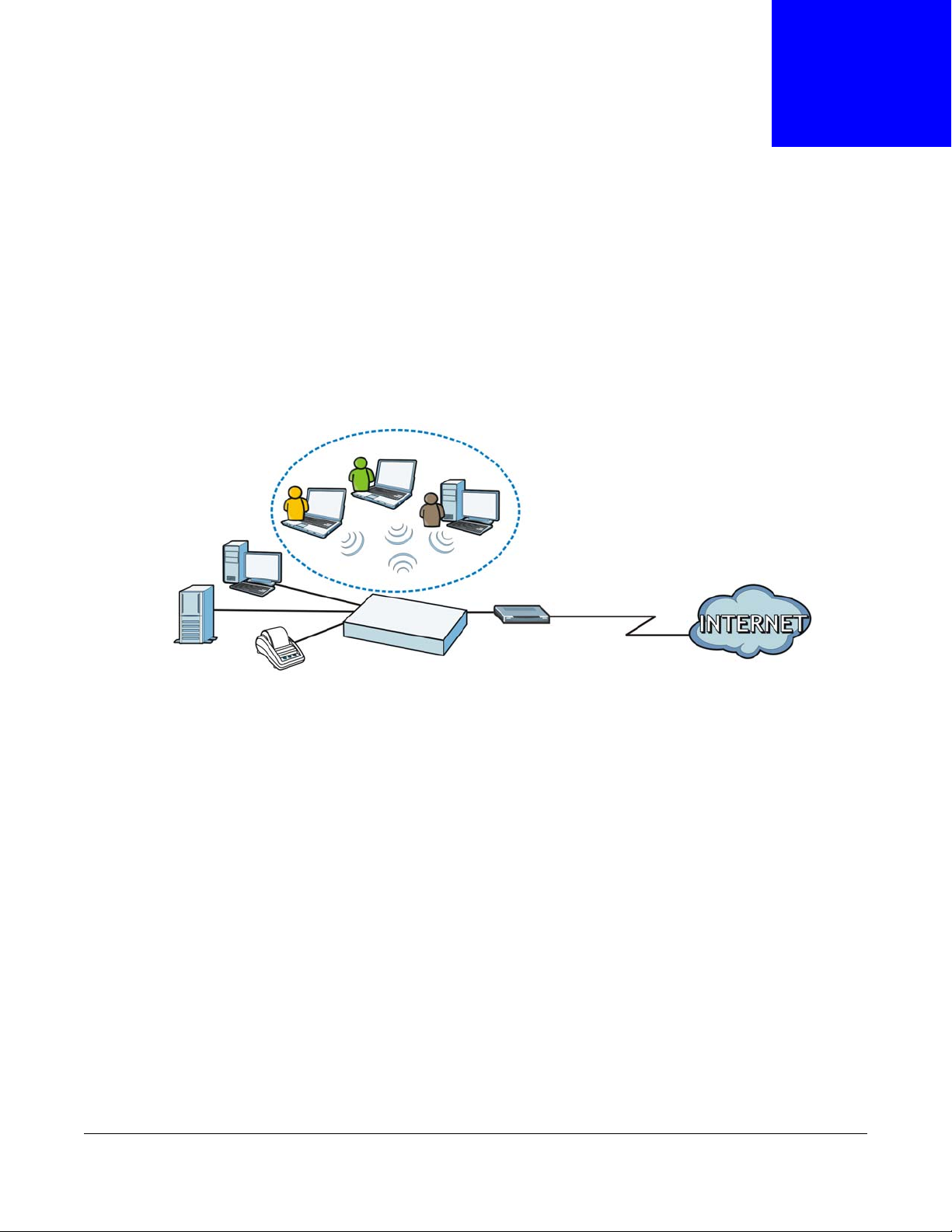
1.1 Overview
The UAG is a comprehensive service gateway. If you have a "statement printer", such as SP350E,
you can connect it directly to the UAG, allowing you to easily print subscriber statements. The UAG
is ideal for offices, coffee shops, libraries, hotels and airport terminals catering to subscribers that
seek Internet access. You should have an Internet account already set up and have been given
usernames, passwords etc. required for Internet access.
CHAPTER 1
Introduction
You can use web authentication to allow guests to access the network only after they authenticate
with the UAG through a specifically designated login web page. You can also forward the
authenticated client's e-mail messages to a specific SMTP server.
The UAG also provides bandwidth management, NAT, port forwarding, policy routing, DHCP server
and many other powerful features. The UAG’s security features include firewall, VPN and
certificates.
The UAG lets you set up multiple networks for your company. The De-Militarized Zone (DMZ)
increases LAN security by providing separate ports for connecting publicly accessible servers. The
UAG also provides two separate LAN networks. You can set ports to be part of the LAN1, LAN2 or
DMZ. Alternatively, you can deploy the UAG as a transparent firewall in an existing network with
minimal configuration.
1.2 Default Zones, Interfaces, and Ports
The default configurations for zones, interfaces, and ports are as follows. References to interfaces
may be generic rather than the specific name used in your model. For example, this guide may use
“the WAN interface” rather than “P1” or” P2”.
UAG5100 User’s Guide
18
Page 19
Chapter 1 Introduction
Physical Ports
Interfaces
Zones LAN1 DMZ
lan1 dmz
LAN2
lan2
WAN
wan1 wan2
P1 P2
P3
P4
P5
Figure 1 Zones, Interfaces, and Physical Ethernet Ports
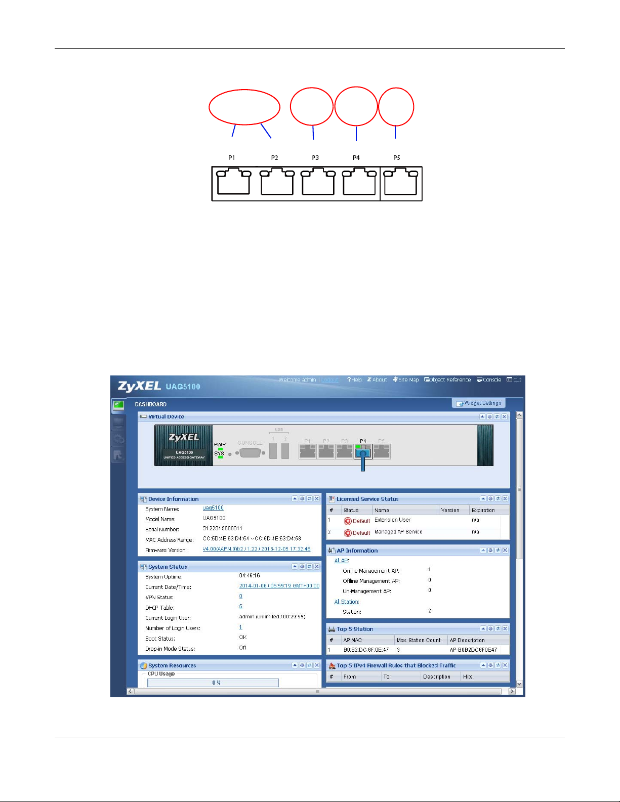
1.3 Management Overview
You can manage the UAG in the following ways.
Web Configurator
The Web Configurator allows easy UAG setup and management using an Internet browser. This
User’s Guide provides information about the Web Configurator.
Figure 2 Managing the UAG: Web Configurator
UAG5100 User’s Guide
19
Page 20
Command-Line Interface (CLI)
The CLI allows you to use text-based commands to configure the UAG. Access it using remote
management (for example, SSH or Telnet) or via the physical or Web Configurator console port.
See the Command Reference Guide for CLI details. The default settings for the console port are:
Table 1 Console Port Default Settings
SETTING VALUE
Speed 115200 bps
Data Bits 8
Parity None
Stop Bit 1
Flow Control Off
1.4 Web Configurator
In order to use the Web Configurator, you must:
Chapter 1 Introduction
• Use one of the following web browser versions: Internet Explorer 7.0 and later versions, Mozilla
Firefox 9.0 and later versions, Safari 4.0 and later versions, or Google Chrome 10.0 and later
versions.
• Allow pop-up windows (blocked by default in Windows XP Service Pack 2)
• Enable JavaScripts, Java permissions, and cookies
The recommended screen resolution is 1024 x 768 pixels and higher.
1.4.1 Web Configurator Access
1 Make sure your UAG hardware is properly connected. See the Quick Start Guide.
2 In your browser go to http://172.16.0.1 or http://172.17.0.1. The Login screen appears.
3 Type the user name (default: “admin”) and password (default: “1234”).
UAG5100 User’s Guide
20
Page 21
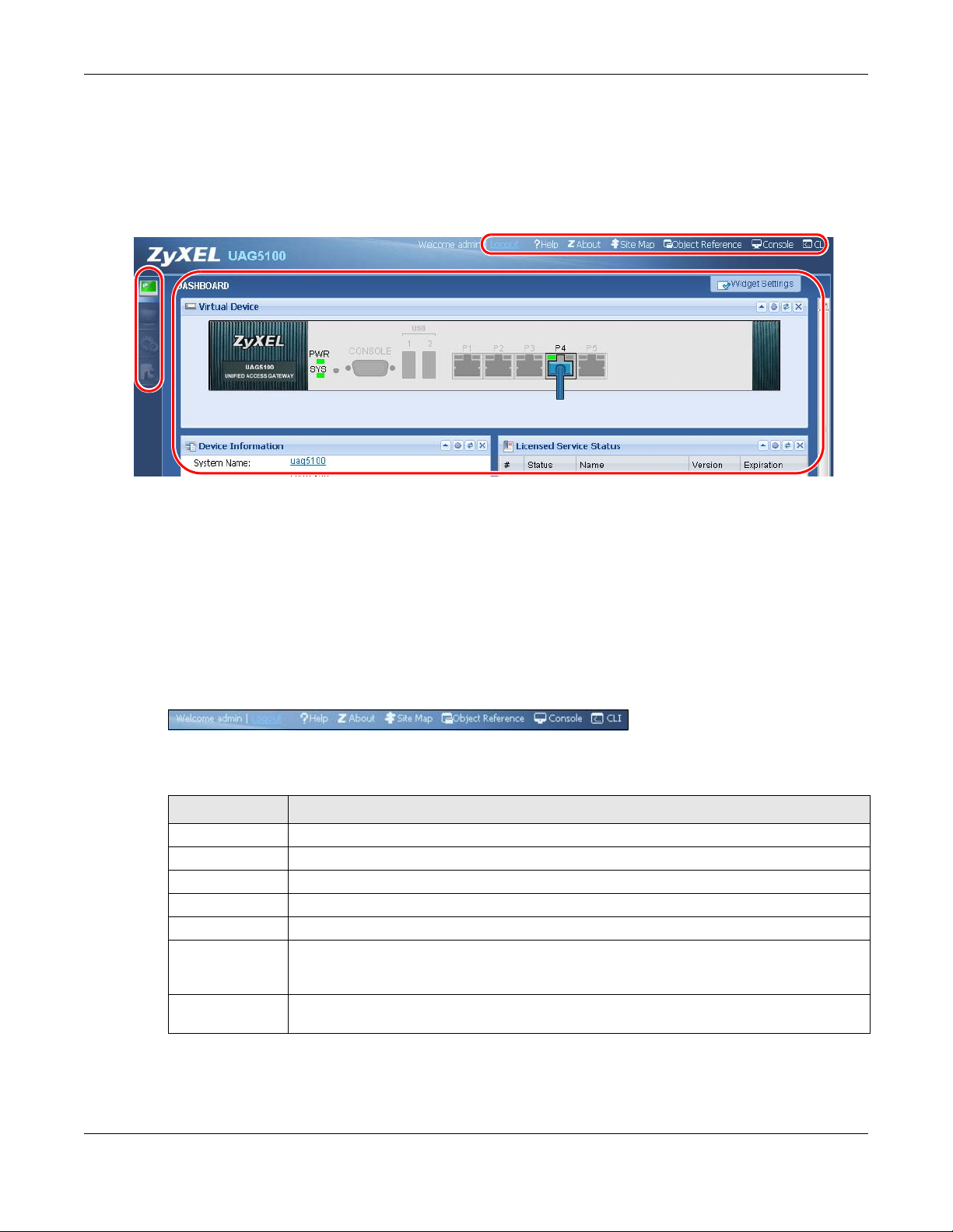
Chapter 1 Introduction
A
C
B
4 Click Login. If you logged in using the default user name and password, the Update Admin Info
screen appears. Otherwise, the dashboard appears.
5 Follow the directions in the Update Admin Info screen. If you change the default password, the
Login screen appears after you click Apply. If you click Ignore, the Installation Setup Wizard
opens if the UAG is using its default configuration; otherwise the dashboard appears.
1.4.2 Web Configurator Screens Overview
The Web Configurator screen is divided into these parts (as illustrated on page 21):
• A - title bar
• B - navigation panel
• C - main window
1.4.2.1 Title Bar
Figure 3 Title Bar
The title bar icons in the upper right corner provide the following functions.
Table 2 Title Bar: Web Configurator Icons
LABEL DESCRIPTION
Logout Click this to log out of the Web Configurator.
Help Click this to open the help page for the current screen.
About Click this to display basic information about the UAG.
Site Map Click this to see an overview of links to the Web Configurator screens.
Object Reference Click this to check which configuration items reference an object.
Console Click this to open a Java-based console window from which you can run command line
interface (CLI) commands. You will be prompted to enter your user name and password.
See the Command Reference Guide for information about the commands.
CLI Click this to open a popup window that displays the CLI commands sent by the Web
Configurator to the UAG.
About
Click About to display basic information about the UAG.
UAG5100 User’s Guide
21
Page 22
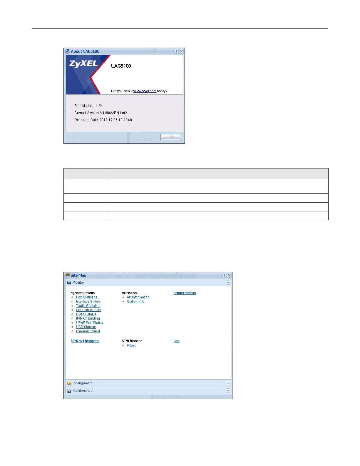
Chapter 1 Introduction
Figure 4 About
The following table describes labels that can appear in this screen.
Table 3 About
LABEL DESCRIPTION
Boot Module This shows the version number of the software that handles the booting process of the
Current Version This shows the firmware version of the UAG.
Released Date This shows the date (yyyy-mm-dd) and time (hh:mm:ss) when the firmware is released.
OK Click this to close the screen.
UAG.
Site Map
Click Site MAP to see an overview of links to the Web Configurator screens. Click a screen’ s link to
go to that screen.
Figure 5 Site Map
UAG5100 User’s Guide
22
Page 23
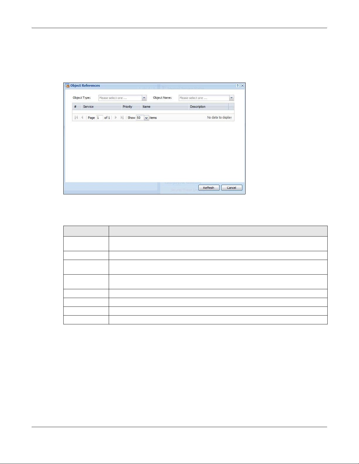
Chapter 1 Introduction
Object Reference
Click Object Reference to open the Object Reference screen. Select the type of object and the
individual object and click Refresh to show which configuration settings reference the object.
Figure 6 Object Reference
The fields vary with the type of object. The following table describes labels that can appear in this
screen.
Table 4 Object References
LABEL DESCRIPTION
Object Name This identifies the object for which the configuration settings that use it are displayed. Click
# This field is a sequential value, and it is not associated with any entry.
Service This is the type of setting that references the selected object. Click a service’s name to
Priority I f i t is applicable, this field lists the referencing configuration item’s position in its list,
Name This field identifies the configuration item that references the object.
Description If the referencing configuration item has a description configured, it displays here.
Refresh Click this to update the information in this screen.
Cancel Click Cancel to close the screen.
the object’s name to display the object’s configuration screen in the main window.
display the service’s configuration screen in the main window.
otherwise N/A displays.
CLI Messages
Click CLI to look at the CLI commands sent by the W eb Configurator. Open the pop-up window and
then click some menus in the web configurator to display the corresponding commands.
UAG5100 User’s Guide
23
Page 24
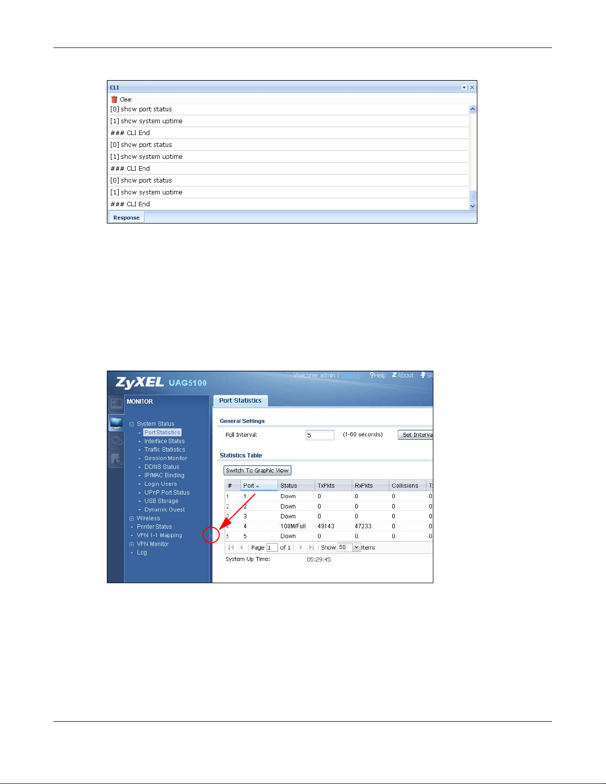
Figure 7 CLI Messages
Click Clear to remove the currently displayed information.
See the Command Reference Guide for information about the commands.
1.4.3 Navigation Panel
Use the navigation panel menu items to open status and configuration screens. Click the arrow in
the middle of the right edge of the navigation panel to hide the panel or drag to resize it. The
following sections introduce the UAG’s navigation panel menus and their screens.
Chapter 1 Introduction
Figure 8 Navigation Panel
Dashboard
The dashboard displays general device information, system status, system resource usage, licensed
service status, and interface status in widgets that you can re-arrange to suit your needs. See
Chapter 6 on page 66 for details on the dashboard.
UAG5100 User’s Guide
24
Page 25

Chapter 1 Introduction
Monitor Menu
The monitor menu screens display status and statistics information.
Table 5 Monitor Menu Screens Summary
FOLDER OR LINK TAB FUNCTION
System Status
Port Statistics Display packet statistics for each physical port.
Interface
Status
Traffic
Statistics
Session
Monitor
DDNS Status Display the status of the UAG’s DDNS domain names.
IP/MAC Binding List the devices that have received an IP address from UAG interfaces using
Login Users List the users currently logged into the UAG.
UPnP Port
Status
USB Storage Display details about a USB device connected to the UAG.
Dynamic Guest List the dynamic guest accounts in the UAG’s local database.
Wireless
AP Information AP List Display information about the connected APs.
Radio List Display information about the radios of the connected APs.
Station Info Display information about the connected stations.
Printer Status
Printer Status Display information about the connected statement printers.
VPN 1-1 Mapping
VPN 1-1
Mapping
Statistics Display statistics for each of the VPN 1-1 mapping rules.
VPN Monitor
IPSec Display and manage the active IPSec SAs.
Log List log entries.
View Log List log entries for the UAG.
View AP Log Allow you to query connected APs and view log entries for them.
Dynamic Users
Log
Display general interface information and packet statistics.
Collect and display traffic statistics.
Display the status of all current sessions.
IP/MAC binding.
List the NAT port mapping rules that UPnP creates on the UAG.
Display the status of the active users to which the UAG applied a VPN 1-1
mapping rule.
Display the UAG’s dynamic guest account log messages.
Configuration Menu
Use the configuration menu screens to configure the UAG’s features.
Table 6 Configuration Menu Screens Summary
FOLDER OR LINK TAB FUNCTION
Quick Setup Quickly configure WAN interfaces or VPN connections.
Licensing
UAG5100 User’s Guide
25
Page 26

Chapter 1 Introduction
Table 6 Configuration Menu Screens Summary (continued)
FOLDER OR LINK TAB FUNCTION
Registration Registration Register the device and activate trial services.
Service View the licensed service status and upgrade licensed services.
Wireless
Controller Configuration Configure how the UAG handles APs that newly connect to the
network.
AP
Management
Network
Interface Port Grouping Use this screen to configure port groups and set the UAG’s flexible
Routing Policy Route Create and manage routing policies.
Zone Configure zones used to define various policies.
DDNS Define and manage the UAG’s DDNS domain names.
NAT Set up and manage port forwarding rules.
VPN 1-1
Mapping
HTTP Redirect Set up and manage HTTP redirection rules.
SMTP Redirect Set up and manage SMTP redirection rules.
ALG Configure SIP, H.323, and FTP pass-through settings.
UPnP enable UPnP and NAT-PMP on your UAG.
IP/MAC
Binding
Layer 2
Isolation
IPnP Enable IPnP on the UAG and the internal interface(s).
Web
Authentication
Firewall Firewall Create and manage level-3 traffic rules.
Billing General Configure the general billing settings, such as the accounting
Mgnt. AP List Edit wireless AP information, remove APs, and reboot them.
ports as WAN1, WAN2, LAN1, LAN2 or DMZ.
Ethernet Manage Ethernet interfaces and virtual Ethernet interfaces.
PPP Create and manage PPPoE and PPTP interfaces.
VLAN Create and manage VLAN interfaces and virtual VLAN interfaces.
Bridge Create and manage bridges and virtual bridge interfaces.
Trunk Create and manage trunks (groups of interfaces) for load
balancing.
Static Route Create and manage IP static routing information.
General Enable and configure VPN 1-1 mapping to assign a public IP
address to each of users that match the rules.
Profile Configure a pool profile which defines the public IP address that the
UAG assigns to the matched users and the interface through which
the user’s traffic is forwarded.
Summary Configure IP to MAC address bindings for devices connected to
each supported interface.
Exempt List Configure ranges of IP addresses to which the UAG does not apply
IP/MAC binding.
General Enable layer-2 isolation on the UAG and the internal interface(s).
White List Enable and configure the white list.
Web Authentication Define rules to force user authentication for network access.
Walled Garden Create walled garden links that display in the login screen.
Advertisement Enable and set advertisement links.
Session Control Limit the number of concurrent client NAT/firewall sessions.
method.
UAG5100 User’s Guide
26
Page 27

Chapter 1 Introduction
Table 6 Configuration Menu Screens Summary (continued)
FOLDER OR LINK TAB FUNCTION
Billing Profile Configure the billing profiles for the web-based account generator
and each button on the connected statement printer.
Discount Configure discount price plans.
Payment Service Enable online payment service and configure the service pages.
Printer Manager General Configure the printer list and enable printer management.
Printout
Configuration
Free Time Free Time Allow users to get a free account for Internet surfing during the
SMS SMS Enable the SMS service to send dynamic guest account information
VPN
IPSec VPN VPN Connection Configure IPSec tunnels.
VPN Gateway Configure IKE tunnels.
BWM BWM Enable and configure bandwidth management rules.
Object
User/Group User Create and manage users.
Group Create and manage groups of users.
Setting Manage default settings for all users, general settings for user
AP Profile Radio Create and manage wireless radio settings files that can be
SSID Create and manage wireless SSID, security, and MAC filtering
Address Address Create and manage host, range, and network (subnet) addresses.
Address Group Create and manage groups of addresses.
Service Service Create and manage TCP and UDP services.
Service Group Create and manage groups of services.
Schedule Schedule Create one-time and recurring schedules.
AAA Server RADIUS Configure the RADIUS settings.
Auth. Method Authentication
Method
Certificate My Certificates Create and manage the UAG’s certificates.
Trusted Certificates Import and manage certificates from trusted sources.
ISP Account ISP Account Create and manage ISP account information for PPPoE/PPTP
System
Host Name Configure the system and domain name for the UAG.
USB Storage Settings Configure the settings for the connected USB devices.
Date/Time Configure the current date, time, and time zone in the UAG.
Console Speed Set the console speed.
DNS Configure the DNS server and address records for the UAG.
WWW Service Control Configure HTTP, HTTPS, and general authentication.
Login Page Configure how the login and access user screens look.
Customize the account printout.
specified time period.
in text messages.
sessions, and rules to force user authentication.
associated with different APs.
settings files that can be associated with different APs.
Create and manage ways of authenticating users.
interfaces.
UAG5100 User’s Guide
27
Page 28
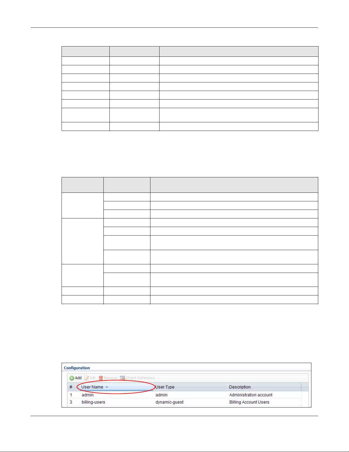
Chapter 1 Introduction
Table 6 Configuration Menu Screens Summary (continued)
FOLDER OR LINK TAB FUNCTION
SSH Configure SSH server and SSH service settings.
TELNET Configure telnet server settings for the UAG.
FTP Configure FTP server settings.
SNMP Configure SNMP communities and services.
Language Select the Web Configurator language.
Log & Report
Email Daily
Report
Log Settings Configure the system log, e-mail logs, and remote syslog servers.
Configure where and how to send daily reports and what reports to
send.
Maintenance Menu
Use the maintenance menu screens to manage configuration and firmware files, run diagnostics,
and reboot or shut down the UAG.
Table 7 Maintenance Menu Screens Summary
FOLDER OR
LINK
File Manager Configuration File Manage and upload configuration files for the UAG.
Diagnostics Diagnostic Collec t diagnostic information.
Packet Flow
Explore
Reboot Restart the UAG.
Shutdown Turn off the UAG.
TAB FUNCTION
Firmware Package View the current firmware version and to upload firmware.
Shell Script Manage and run shell script files for the UAG.
Packet Capture Capture packets for analysis.
Core Dump Connect a USB device to the UAG and save the UAG operating system
kernel to it here.
System Log Connect a USB device to the UAG and archive the UAG system logs to it
here.
Routing Status Check how the UAG determines where to route a packet.
SNAT Status View a clear picture on how the UAG converts a packet’s source IP
address and check the related settings.
1.4.4 Tables and Lists
Web Configurator tables and lists are flexible with several options for how to display their entries.
Click a column heading to sort the table’s entries according to that column’s criteria.
Figure 9 Sorting Table Entries by a Column’s Criteria
UAG5100 User’s Guide
28
Page 29
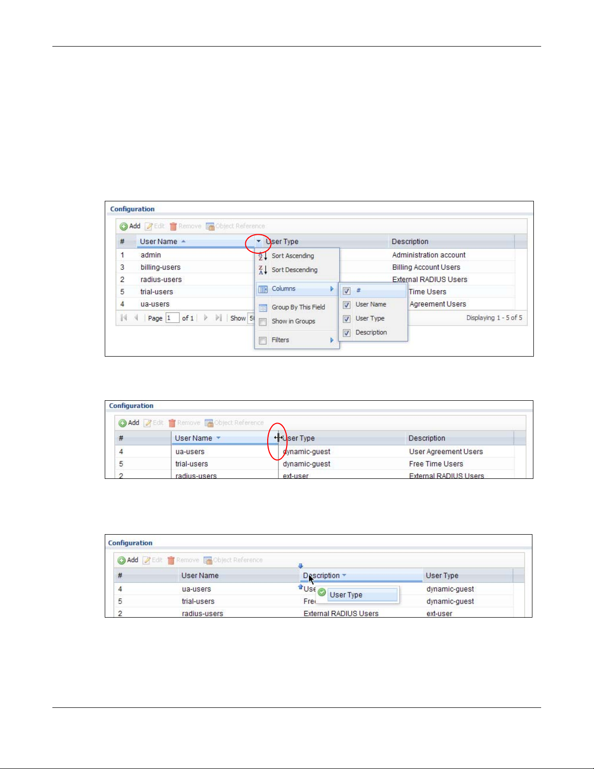
Chapter 1 Introduction
Click the down arrow next to a column heading for more options about how to display the entries.
The options available vary depending on the type of fields in the column. Here are some examples
of what you can do:
• Sort in ascending or descending (reverse) alphabetical order
• Select which columns to display
• Group entries by field
• Show entries in groups
• Filter by mathematical operators (<, >, or =) or searching for text
Figure 10 Common Table Column Options
Select a column heading cell’s right border and drag to re-size the column.
Figure 11 Resizing a Table Column
Select a column heading and drag and drop it to change the column order. A green check mark
displays next to the column’s title when you drag the column to a valid new location.
Figure 12 Moving Columns
Use the icons and fields at the bottom of the table to navigate to different pages of entries and
control how many entries display at a time.
UAG5100 User’s Guide
29
Page 30
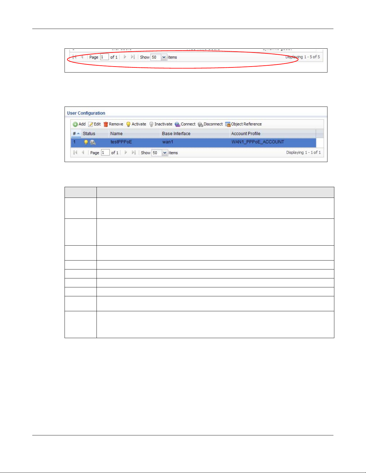
Chapter 1 Introduction
Figure 13 Navigating Pages of Table Entries
The tables have icons for working with table entries. You can often use the [Shift] or [Ctrl] key to
select multiple entries to remove, activate, or deactivate.
Figure 14 Common Table Icons
Here are descriptions for the most common table icons.
Table 8 Common Table Icons
LABEL DESCRIPTION
Add Click this to create a new entry. For features where the entry’s position in the numbered list is
Edit Double-click an entry or select it and click Edit to open a screen where you can modify the
Remove To remove an entry, select it and click Remove. The UAG confirms you want to remove it before
Activate To turn on an entry, select it and click Activate.
Inactivate To turn off an entry, select it and click Inactivate.
Connect To connect an entry, select it and click Connect.
Disconnect To disconnect an entry, selec t i t and click Disconnect.
Object
Reference
Move To change an entry’s position in a numbered list, select it and click Move to display a field to
important (features where the UAG applies the table’s entries in order like the firewall for
example), you can select an entry and click Add to create a new entry after the selected entry.
entry’s settings. In some tables you can just click a table entry and edit it directly in the table.
For those types of tables small red triangles display for table entries with changes that you have
not yet applied.
doing so.
Select an entry and click Object Reference to check which settings use the entry.
type a number for where you want to put that entry and press [ENTER] to move the entry to the
number that you typed. For example, if you type 6, the entry you are moving becomes number 6
and the previous entry 6 (if there is one) gets pushed up (or down) one.
Working with Lists
When a list of available entries displays next to a list of selected entries, you can often just doubleclick an entry to move it from one list to the other. In some lists you can also use the [Shift] or
[Ctrl] key to select multiple entries, and then use the arrow button to move them to the other list.
UAG5100 User’s Guide
30
Page 31

Figure 15 Working with Lists
1.5 Stopping the UAG
Always use Maintenance > Shutdown > Shutdown or the shutdown command before you turn
off the UAG or remove the power. Not doing so can cause the firmware to become corrupt.
Chapter 1 Introduction
UAG5100 User’s Guide
31
Page 32

Hardware Installation and Connection
2.1 Rack-mounting
Use the following steps to mount the UAG on an EIA standard size, 19-inch rack or in a wiring closet
with other equipment using a rack-mounting kit. Make sure the rack will safely support the
combined weight of all the equipment it contains and that the position of the UAG does not make
the rack unstable or top-heavy. Take all necessary precautions to anchor the rack securely before
installing the unit.
Note: Leave 10 cm of clearance at the sides and 20 cm in the rear.
Use a #2 Phillips screwdriver to install the screws.
Note: Failure to use the proper screws may damage the unit.
CHAPTER 2
1 Align one bracket with the holes on one side of the UAG and secure it with the included bracket
screws (smaller than the rack-mounting screws).
2 Attach the other bracket in a similar fashion.
3 After attaching both mounting brackets, position the UAG in the rack and up the bracket holes with
the rack holes. Secure the UAG to the rack with the rack-mounting screws.
UAG5100 User’s Guide
32
Page 33

2.2 Front Panel
This section introduces the UAG’s front panel.
Figure 16 UAG Front Panel
Ethernet Ports
The 1000Base-T auto-negotiating, auto-crossover Ethernet ports support 10/100/1000 Mbps
Gigabit Ethernet so the speed can be 100 Mbps or 1000 Mbps. The duplex mode is full at 1000
Mbps and half or full at 10/100 Mbps. An auto-negotiating port can detect and adjust to the
optimum Ethernet speed (10/100/1000 Mbps) and duplex mode (full duplex or half duplex) of the
connected device. An auto-crossover (auto-MDI/MDI-X) port automatically works with a straightthrough or crossover Ethernet cable. The factory default negotiation settings for the Ethernet ports
on the UAG are speed: auto, duplex: auto, and flow control: on (you cannot configure the flow
control setting, but the UAG can negotiate with the peer and turn it off if needed).
Chapter 2 Hardware Installation and Connection
The color-coded Ethernet port supports the IEEE 802.3at High Power over Ethernet (PoE) standard
and can receive power of up to 30W per Ethernet port from a PoE switch via an 8-pin CAT 5
Ethernet cable. This helps eliminate the need for power sockets.
USB 2.0 Ports
Connect a USB storage device to a USB port on the UAG to archiv e the UAG system logs or sa ve the
UAG operating system kernel to it.
Console Port
Connect this port to your computer (using an RS-232 cable) if you want to configure the UAG using
the command line interface (CLI) via the console port.
For local management, you can use a computer with terminal emulation software
configured to the following parameters:
• VT100 terminal emulation
• 115200 bps
• No parity, 8 data bits, 1 stop bit
• No flow control
Connect the male 9-pin end of the RS-232 console cable to the console port of the UAG.
Connect the female end to a serial port (COM1, COM2 or other COM port) of your
computer.
UAG5100 User’s Guide
33
Page 34

2.2.1 Front Panel LEDs
The following tables describe the LEDs.
Table 9 Front Panel LEDs
LED COLOR STATUS DESCRIPTION
PWR Off The UAG is turned off.
Green On The UAG is turned on.
Red On There is a hardware component failure. Shut down the device, wait for a few
SYS Green Off The UAG is not ready or has failed.
On The UAG is ready and running.
Blinking The UAG is booting.
Red On The UAG had an error or has failed.
P1~P5 Green On This port has a successful link to a 10/100 Mbps Ethernet network
Blinking The UAG is sending or re ceiving packets to/from a 10/100 Mbps Ethernet
Orange On This port has a successful link to a 1000 Mbps Ethernet network.
Blinking The UAG is sending or receiving packets to/from a 1000 Mbps Ethernet
Off There is no connection on this port.
Chapter 2 Hardware Installation and Connection
minutes and then restart the device (see Section 1.5 on page 31). If the LED
turns red again, then please contact your vendor.
network on this port
network on this port
2.3 Rear Panel
The following figure shows the rear panel of the UAG. The rear panel contains a connector
for the power receptacle.
Figure 17 Rear Panel
UAG5100 User’s Guide
34
Page 35

3.1 Overview
This chapter shows you how to set up an external statement printer (SP350E for example) and
deploy it in your network with the UAG.
In the following examples, you will:
• Attach the printer to the UAG.
• Set up an Internet connection on the UAG.
• Allow the UAG to monitor and manage the printer.
• Turn on web authentication on the UAG.
• Generate a free guest account.
CHAPTER 3
Printer Deployment
3.2 Attach the Printer to the UAG
This section uses the SP350E as an example. Refer to the printer documentation for detailed
information about paper loading.
1 Connect the Ethernet port of the printer to one LAN port of the UAG.
2 Connect the power socket of the printer to a power outlet. Turn on the printer.
The printer is acting as a DHCP client by default and will obtain an IP address from the connected
UAG. Make sure the UAG is turned on already and the DHCP server is enabled on its LAN
interface(s).
3.3 Set up an Internet Connection on the UAG
1 Connect the WAN port of the UAG to a broadband modem or router.
2 Connect your computer to one of the available LAN port on the UAG.
3 Log into the UAG web configurator. See Section 1.4 on page 20 on how to access the web
configurator.
4 Enter your Internet access information to set up a Internet connection. See Chapter 4 on page 43
for detailed information on how to use the setup wizard.
UAG5100 User’s Guide
35
Page 36

Chapter 3 Printer Deployment
3.4 Allow the UAG to Monitor and Manage the Printer
Before you add the printer to the UAG’s printer list, check the sticker on the printer’s rear panel to
see its MAC address.
1 Go to the Dashboard of the UAG web configurator.
2 Open the DHCP Table to find the IP address that is assigned to the printer’s MAC address. Make
sure the IP address is reserved for the printer. Write down the printer’s IP address.
UAG5100 User’s Guide
36
Page 37

Chapter 3 Printer Deployment
3 Go to the Configuration > Printer Manager screen. Click Add in the Printer List to create a
new entry for your printer.
4 After the printer’s IP address is added to the printer list, select the Enable Printer Manager
checkbox and then click Apply.
UAG5100 User’s Guide
37
Page 38

Chapter 3 Printer Deployment
5 Go to the Monitor > Printer Status screen to check if the UAG can connect to the printer (the
printer status is sync success). In this screen, you can also click Discover Printer to detect and
display the printer that is connected to the UAG, and then click Add to Mgnt Printer List to add
the selected AP to the managed printer list automatically.
Note: You may need to wait up to 90 seconds for the UAG to synchroni ze with the printer
successfully after you click Apply in the Configuration > Printer Manager
screen.
3.5 Turn on Web Authentication on the UAG
With web authentication, users need to log in through a designated web page before they can
access the network(s).
UAG5100 User’s Guide
38
Page 39

Chapter 3 Printer Deployment
1 Go to the Configuration > Web Authentication screen.
2 Set Authentication to Web Portal.
3 Select Internal Web Portal to use the default login page.
4 Click Add to create a new web authentication policy.
5 The Auth. Policy Add screen displays. Set Authentication to required and select Force User
Authentication to redirect all HTTP traffic to the default login page.
6 Click OK to save your changes.
UAG5100 User’s Guide
39
Page 40

Chapter 3 Printer Deployment
7 Click Apply the Configuration > Web Authentication screen.
3.6 Generate a Free Guest Account
You can use the buttons on the printer or web-based account generator to create guest accounts
based on the pre-defined billing settings (see Section 26.3 on page 261).
1 Go to the Configuration > Free Time screen.
2 Select the Enable Free Time checkbox to turn on this feature. Click Apply.
3 Whenever a user tries to access a web page, he/she will be redirect to the default login page.
4 Click the link on the login page to get a free guest account.
UAG5100 User’s Guide
40
Page 41

Chapter 3 Printer Deployment
5 A Welcome screen displays. Select the free time service. Click OK to generate and show the
account information on the web page.
6 Now you can use this account to access the Internet through the UAG for
UAG5100 User’s Guide
41
Page 42

Chapter 3 Printer Deployment
UAG5100 User’s Guide
42
Page 43

CHAPTER 4
Installation Setup Wizard
4.1 Installation Setup Wi zard Screens
When you log into the Web Configurator for the first time or when you reset the UAG to its default
configuration, the Installation Setup Wizard screen displays. This wizard helps you configure
Internet connection settings and activate subscription services. This chapter provides information
on configuring the Web Configurator's installation setup wizard. See the feature-specific chapters in
this User’s Guide for background information.
Figure 18 Installation Setup Wizard
• Click the double arrow in the upper right corner to display or hide the help.
• Click Go to Dashboard to skip the installation setup wizard or click Next to start configuring for
Internet access.
4.1.1 Internet Access Setup - WAN Interface
Use this screen to set how many WAN interfaces to configure and the first WAN interface’s type of
encapsulation and method of IP address assignment.
The screens vary depending on the encapsulation type. Refer to information provided by your ISP
to know what to enter in each field. Leave a field blank if you don’t have that information.
Note: Enter the Internet access information exactly as your ISP gave it to you.
UAG5100 User’s Guide
43
Page 44

Chapter 4 Installation Setup Wizard
Figure 19 Internet Access: Step 1: First WAN Interface
• I have two ISPs: Select this option to configure two Internet connections. Leave it cleared to
configure just one. This option appears when you are configuring the first WAN interface.
• Encapsulation: Choose the Ethernet option when the WAN port is used as a regular Ethernet.
Otherwise, choose PPP Over Ethernet (PPPoE) or PPTP for a dial-up connection according to
the information from your ISP.
• First WAN Interface: This is the interface you are configuring for Internet access.
• Zone: This is the security zone to which this interface and Internet connection belong.
• IP Address Assignment: Select Auto if your ISP did not assign you a fixed IP address.
Select Static if the ISP assigned a fixed IP address.
4.1.2 Internet Access: Ethernet
This screen is read-only if you set the previous screen’s IP Address Assignment field to Auto.
Use this screen to configure your IP address settings.
Note: Enter the Internet access information exactly as given to you by your ISP.
UAG5100 User’s Guide
44
Page 45

Chapter 4 Installation Setup Wizard
Figure 20 Internet Access: Ethernet Encapsulation
• Encapsulation: This displays the type of Internet connection you are configuring.
• First WAN Interface: This is the number of the interface that will connect with your ISP.
• Zone: This is the security zone to which this interface and Internet connection will belong.
• IP Address: Enter your (static) public IP address. Auto displays if you selected Auto as the IP
Address Assignment in the previous screen.
The following fields display if you selected static IP address assignment.
• IP Subnet Mask: Enter the subnet mask for this WAN connection's IP address.
• Gateway IP Address: Enter the IP address of the router through which this WAN connection
will send traffic (the default gateway).
• First / Second DNS Server: These fields display if you selected static IP address assignment.
The Domain Name System (DNS) maps a domain name to an IP address and vice versa. Enter a
DNS server's IP address(es). The DNS server is extremely important because without it, you
must know the IP address of a computer before you can access it. The UAG uses these (in the
order you specify here) to resolve domain names for DDNS and the time server. Leave the field
as 0.0.0.0 if you do not want to configure DNS servers.
4.1.3 Internet Access: PPPoE
Note: Enter the Internet access information exactly as given to you by your ISP.
UAG5100 User’s Guide
45
Page 46

Chapter 4 Installation Setup Wizard
Figure 21 Internet Access: PPPoE Encapsulation
4.1.3.1 ISP Parameters
• T ype the PPPoE Se rvice Name from your service provider. PPPoE uses a service name to identify
and reach the PPPoE server. You can use alphanumeric and -_@$./ characters, and it can be up
to 64 characters long.
• Authentication Type - Select an authentication protocol for outgoing connection requests.
Options are:
• CHAP/PAP - Your UAG accepts either CHAP or PAP when requested by the remote node.
• CHAP - Your UAG accepts CHAP only.
• PAP - Your UAG accepts PAP only.
• MSCHAP - Your UAG accepts MSCHAP only.
• MSCHAP-V2 - Your UAG accepts MSCHAP-V2 only.
•Type the User Name given to you by your ISP. You can use alphanumeric and -_@$./ char acters,
and it can be up to 31 characters long.
•Type the Password associated with the user name. Use up to 64 ASCII characters except the []
and ?. This field can be blank.
•Select Nailed-Up if you do not want the connection to time out. Otherwise, type the Idle
Timeout in seconds that elapses before the router automatically disconnects from the PPPoE
server.
4.1.3.2 WAN IP Address Assignments
• First WAN Interface: This is the name of the interface that will connect with your ISP.
• Zone: This is the security zone to which this interface and Internet connection will belong.
• IP Address: Enter your (static) public IP address. Auto displays if you selected Auto as the IP
Address Assignment in the previous screen.
UAG5100 User’s Guide
46
Page 47

Chapter 4 Installation Setup Wizard
• First / Second DNS Server: These fields display if you selected static IP address assignment.
The Domain Name System (DNS) maps a domain name to an IP address and vice versa. Enter a
DNS server's IP address(es). The DNS server is extremely important because without it, you
must know the IP address of a computer before you can access it. The UAG uses these (in the
order you specify here) to resolve domain names for DDNS and the time server. Leave the field
as 0.0.0.0 if you do not want to configure DNS servers. If you do not configure a DNS server, you
must know the IP address of a machine in order to access it.
4.1.4 Internet Access: PPTP
Note: Enter the Internet access information exactly as given to you by your ISP.
Figure 22 Internet Access: PPTP Encapsulation
4.1.4.1 ISP Parameters
• Authentication Type - Select an authentication protocol for outgoing calls. Options are:
• CHAP/PAP - Your UAG accepts either CHAP or PAP when requested by the remote node.
• CHAP - Your UAG accepts CHAP only.
• PAP - Your UAG accepts PAP only.
• MSCHAP - Your UAG accepts MSCHAP only.
• MSCHAP-V2 - Your UAG accepts MSCHAP-V2 only.
UAG5100 User’s Guide
47
Page 48

•Type the User Name given to you by your ISP. You can use alphanumeric and -_@$./ char acters,
and it can be up to 31 characters long.
•Type the Password associated with the user name. Use up to 64 ASCII characters except the []
and ?. This field can be blank. Re-type your password in the next field to confirm it.
•Select Nailed-Up if you do not want the connection to time out. Otherwise, type the Idle
Timeout in seconds that elapses before the router automatically disconnects from the PPTP
server.
4.1.4.2 PPTP Configuration
• Base Interface: This identifies the Ethernet interface you configure to connect with a modem or
router.
•Type a Base IP Address (static) assigned to you by your ISP.
• Type the IP Subnet Mask assigned to you by your ISP (if given).
• Gateway IP Address: Enter the IP address of the gateway if any.
• Server IP: Type the IP address of the PPTP server.
•Type a Connection ID or connection name. It must follow the “c:id” and “n:name” format. For
example, C:12 or N:My ISP. This field is optional and depends on the requirements of your
broadband modem or router. You can use alphanumeric and -_: characters, and it can be up to
31 characters long.
Chapter 4 Installation Setup Wizard
4.1.4.3 WAN IP Address Assignments
• First WAN Interface: This is the connection type on the interface you are configuring to
connect with your ISP.
• Zone This is the security zone to which this interface and Internet connection will belong.
• IP Address: Enter your (static) public IP address. Auto displays if you selected Auto as the IP
Address Assignment in the previous screen.
• First / Second DNS Server: These fields display if you selected static IP address assignment.
The Domain Name System (DNS) maps a domain name to an IP address and vice versa. Enter a
DNS server's IP address(es). The DNS server is extremely important because without it, you
must know the IP address of a computer before you can access it. The UAG uses these (in the
order you specify here) to resolve domain names for DDNS and the time server. Leave the field
as 0.0.0.0 if you do not want to configure DNS servers.
4.1.5 Internet Access Setup - Second WAN Interface
If you selected I have two ISPs, after you configure the First WAN Interface, you can configure
the Second WAN Interface. The screens for configuring the second WAN interface are similar to
the first (see Section 4.1.1 on page 43).
UAG5100 User’s Guide
48
Page 49

Chapter 4 Installation Setup Wizard
Figure 23 Internet Access: Step 1: Second WAN Interface
4.1.6 Internet Access - Finish
You have set up your UAG to access the Internet. A screen displays with your settings. If they are
not correct, click Back.
Figure 24 Internet Access: Finish
Click Next and use the following screen to perform a basic registration (see Section 4.2 on page
50).
UAG5100 User’s Guide
49
Page 50

Chapter 4 Installation Setup Wizard
Alternatively, close the window to exit the wizard.
4.2 Device Registration
Go to http://portal.myZyXEL.com with the UAG’s serial number and LAN MAC address to register it
if you have not already done so.
Note: You must be connected to the Internet to register . Use the Registration > Service
screen to update your service subscription status.
Figure 25 Regis tration
UAG5100 User’s Guide
50
Page 51

5.1 Quick Setup Overview
The Web Configurator's quick setup wizards help y o u configu re Intern et and VPN connection
settings. This chapter provides information on configuring the quick setup screens in the Web
Configurator. See the feature-specific chapters in this User’s Guide for background information.
In the Web Configur ator, click Configuration > Quick Setup to open the first Quick Setup
screen.
Figure 26 Quick Setup
CHAPTER 5
Quick Setup Wizards
•WAN Interface
Click this link to open a wizard to set up a WAN (Internet) connection. This wizard creates
matching ISP account settings in the UAG if you use PPPoE or PPTP. See Section 5.2 on page 51.
•VPN Setup
Use VPN Setup to configure a VPN (Virtual Private Network) rule for a secure connection to
another computer or network. See Section 5.3 on page 56.
5.2 WAN Interface Quick Setup
Click WAN Interface in the main Quick Setup screen to open the WAN Interface Quick Setup
Wizard Welcome screen. Use these screens to configure an interface to connect to the Internet.
Click Next.
UAG5100 User’s Guide
51
Page 52

Chapter 5 Quick Setup Wizards
Figure 27 WAN Interface Quick Setup Wizard
5.2.1 Choose an Ethernet Interface
Select the Ethernet interface that you want to configure for a WAN connection and click Next.
Figure 28 Choose an Ethernet Interface
5.2.2 Select WAN Type
WAN Type Selection: Select the type of encapsulation this connection is to use. Choose Ethernet
when the WAN port is used as a regular Ethernet.
Otherwise, choose PPPoE or PPTP for a dial-up connection according to the information from your
ISP.
UAG5100 User’s Guide
52
Page 53

Chapter 5 Quick Setup Wizards
Figure 29 WAN Interface Setup: Step 2
The screens vary depending on what encapsulation type you use. Refer to information provided by
your ISP to know what to enter in each field. Leave a field blank if you don’t have that information.
Note: Enter the Internet access information exactly as your ISP gave it to you.
5.2.3 Configure WAN IP Settings
Use this screen to select whether the interface should use a fixed or dynamic IP address.
Figure 30 WAN Interface Setup: Step 2
• WAN Interface: This is the interface you are configuring for Internet access.
• Zone: This is the security zone to which this interface and Internet connection belong.
• IP Address Assignment: Select Auto If your ISP did not assign you a fixed IP address.
Select Static if you have a fixed IP address.
5.2.4 ISP and WAN Connection Settings
Use this screen to configure the ISP and WAN interface settings. This screen is read-only if you
select Ethernet and set the IP Address Assignment to Auto. If you set the IP Address
Assignment to Static and/or select PPTP or PPPoE, enter the Internet access information exactly
as your ISP gave it to you.
UAG5100 User’s Guide
53
Page 54

Chapter 5 Quick Setup Wizards
Figure 31 ISP and WAN Connection Settings: (PPTP Shown)
The following table describes the labels in this screen.
Table 10 ISP and WAN Connection Settings
LABEL DESCRIPTION
ISP Parameter This section appears if the interface uses a PPPoE or PPTP Internet connection.
Encapsulation This displays the type of Internet connection you are configuring.
Authentication
Type
User Name Type the user name given to you by your ISP. You can use alphanumeric and -_
Password T ype the password associated with the user name abo ve. Use up to 64 ASCII characters
Retype to
Confirm
Nailed-Up Select Nailed-Up if you do not want the connection to time out.
Idle Timeout Type the time in seconds that elapses before the router automatically disconnects from
PPTP Configuration This section only appears if the interface uses a PPPoE or PPTP Internet connection.
Use the drop-down list box to select an authentication protocol for outgoing calls.
Options are:
CHAP/PAP - Your UAG accepts either CHAP or PAP when requested by this remote
node.
CHAP - Your UAG accepts CHAP only.
PAP - Your UAG accepts PAP only.
MSCHAP - Your UAG accepts MSCHAP only.
MSCHAP-V2 - Your UAG accepts MSCHAP-V2 only.
characters, and it can be up to 31 characters long.
except the [] and ?. This field can be blank.
Type your password again for confirmation.
the PPPoE server. 0 means no timeout.
@$./
UAG5100 User’s Guide
54
Page 55

Chapter 5 Quick Setup Wizards
Table 10 ISP and WAN Connection Settings (continued)
LABEL DESCRIPTION
Base Interface This displays the identity of the Ethernet interface you configure to connect wit h a
modem or router.
Base IP Address Type the (static) IP address assigned to you by your ISP.
IP Subnet Mask Type the subnet mask assigned to you by your ISP (if given).
Server IP Type the IP address of the PPTP server.
Connection ID Enter the connection ID or connection name in this field. It must follow the "c:id" and
"n:name" format. For example, C:12 or N:My ISP.
This field is optional and depends on the requirements of your DSL modem.
You can use alphanumeric and -_
WAN Interface
Setup
WAN Interface This displays the identity of the interface you configure to connect with your ISP.
Zone This field displays to which security zone this interface and Internet connection will
belong.
IP Address This field is read-only when the WAN interface uses a dynamic IP address. If your WAN
interface uses a static IP address, enter it in this field.
First DNS
Server
Second DNS
Server
Back Click Back to return to the previous screen.
Next Click Next to continue.
These fields only display for an interface with a static IP address. Enter the DNS server
IP address(es) in the field(s) to the right.
Leave the field as 0.0.0.0 if you do not want to configure DNS servers. If you do not
configure a DNS server, you must know the IP address of a machine in order to access
it.
DNS (Domain Name System) is for mapping a domain name to its corresponding IP
address and vice versa. The DNS server is extremely important because without it, you
must know the IP address of a computer before you can access it. The UAG uses a
system DNS server (in the order you specify here) to resolve domain names for VPN,
DDNS and the time server.
: characters, and it can be up to 31 characters long.
5.2.5 Quick Setup Interface Wizard: Summary
This screen displays the WAN interface’s settings.
UAG5100 User’s Guide
55
Page 56

Chapter 5 Quick Setup Wizards
Figure 32 Interface Wizard: Summary WAN (Ethernet Shown)
The following table describes the labels in this screen.
Tab le 11 Interface Wizard: Summary WAN
LABEL DESCRIPTION
Encapsulation This displays what encapsulation this interface uses to connect to the Internet.
Service Name This field only appears for a PPPoE interface. It displays the PPPoE service name specified
Server IP This field only appears for a PPTP interface. It displays the IP address of the PPTP server.
User Name This is the user name given to you by your ISP.
Nailed-Up If No displays the connection will not time out. Yes means the UAG uses the idle timeout.
Idle Timeout This is how many seconds the connection can be idle before the router automatically
Connection ID If you specified a connection ID, it displays here.
WAN Interface This identifies the interface you configure to connect with your ISP.
Zone This field displays to which security zone this interface and Internet connection will belong.
IP Address
Assignment
IP Address This field displays the WAN IP address.
IP Subnet Mask This field only appears for an Ethernet interface. It displays the interface’s IP subnet mask.
Gateway IP
Address
First DNS Server
Second DNS
Server
Close Click Close to exit the wizard.
in the ISP account.
disconnects from the PPPoE server. 0 means no timeout.
This field displays whether the WAN IP address is static or dynamic (Auto).
This field only appears for an Ethernet interface. It displays the IP address of the gatewa y.
If the IP Address Assignment is Static, these fields display the DNS server IP
address(es).
5.3 VPN Setup Wizard
Click VPN Setup in the main Quick Setup screen to open the VPN Setup Wizard Welcome screen.
UAG5100 User’s Guide
56
Page 57

Figure 33 VPN Setup Wizard
5.3.1 Welcome
Use wizards to create Virtual Private Network (VPN) rules. After you complete the wizard, the Phase
1 rule settings appear in the VPN > IPSec VPN > VPN Gateway screen and the Phase 2 rule
settings appear in the VPN > IPSec VPN > VPN Connection screen.
Figure 34 VPN Wizard Welcome
Chapter 5 Quick Setup Wizards
5.3.2 VPN Setup Wizard: Wizard Type
Choose Express to create a VPN rule with the default phase 1 and phase 2 settings to connect to
another ZLD-based UAG using a pre-shared key.
Choose Advanced to change the default settings and/or use certificates instead of a pre-shared
key to create a VPN rule to connect to another IPSec device.
UAG5100 User’s Guide
57
Page 58

Chapter 5 Quick Setup Wizards
Figure 35 VPN Setup Wizard: Wizard Type
5.3.3 VPN Express Wizard - Scenario
Click the Express radio button as shown in Figure 35 on page 58 to display the following screen.
Figure 36 VPN Express Wizard: Scenario
Rule Name: Type the name used to identify this VPN connection (and VPN gateway). You may use
1-31 alphanumeric characters, underscores (_), or dashes (-), but the first character cannot be a
number. This value is case-sensitive.
Application Scenario: This shows the scenario that the UAG supports.
UAG5100 User’s Guide
58
Page 59

Chapter 5 Quick Setup Wizards
• Site-to-site - The remote IPSec device has a static IP address or a domain name. This UAG can
initiate the VPN tunnel.
5.3.4 VPN Express Wizard - Configuration
Figure 37 VPN Express Wizard: Configuration
• Secure Gateway: Enter the WAN IP address or domain name of the remote IPSec device
(secure gateway) to identify the remote IPSec router by its IP address or a domain name.
• Pre-Shared Key: T ype the password. Both ends of the VPN tunnel must use the same password.
Use 8 to 31 case-sensitive ASCII characters or 8 to 31 pairs of hexadecimal (“0-9”, “A-F”)
characters. Proceed a hexadecimal key with “0x”. You will receive a PYLD_MALFORMED (payload
malformed) packet if the same pre-shared key is not used on both ends.
• Local Policy (IP/Mask): Type the IP address of a computer on your network that can use the
tunnel. You can also specify a subnet. This must match the remote IP address configured on the
remote IPSec device.
• Remote Policy (IP/Mask): T ype the IP address of a computer behind the remote IPSec device.
You can also specify a subnet. This must match the local IP address configured on the remote
IPSec device.
5.3.5 VPN Express Wizard - Summary
This screen provides a read-only summary of the VPN tunnel’s configuration and commands that
you can copy and paste into another ZLD-based UAG’s command line interface to configure it.
UAG5100 User’s Guide
59
Page 60

Chapter 5 Quick Setup Wizards
Figure 38 VPN Express Wizard: Summary
• Rule Name: Identifies the VPN gateway policy.
• Secure Gateway: IP address or domain name of the remote IPSec device.
• Pre-Shared Key: VPN tunnel password. It identifies a communicating party during a phase 1
IKE negotiation.
• Local Policy: IP address and subnet mask of the computers on the network behind your UAG
that can use the tunnel.
• Remote Policy: IP address and subnet mask of the computers on the network behind the
remote IPSec device that can use the tunnel.
• Copy and paste the Configuration for Secure Gateway commands into another ZLD-based
UAG’s command line interface to configure it to serve as the other end of this VPN tunnel. You
can also use a text editor to save these commands as a shell script file with a “.zysh” filename
extension. Use the file manager to run the script in order to configure the VPN connection. See
the commands reference guide for details on the commands displayed in this list.
5.3.6 VPN Express Wizard - Finish
Now the rule is configured on the UAG. The Phase 1 rule settings appear in the VPN > IPSec VPN
> VPN Gateway screen and the Phase 2 rule settings appear in the VPN > IPSec VPN > VPN
Connection screen.
UAG5100 User’s Guide
60
Page 61

Chapter 5 Quick Setup Wizards
Figure 39 VPN Express Wizard: Finish
Click Close to exit the wizard.
5.3.7 VPN Advanced Wizard - Scenario
Click the Advanced radio button as shown in Figure 35 on page 58 to display the following screen.
Figure 40 VPN Advanced Wizard: Scenario
Rule Name: Type the name used to identify this VPN connection (and VPN gateway). You may use
1-31 alphanumeric characters, underscores (_), or dashes (-), but the first character cannot be a
number. This value is case-sensitive.
UAG5100 User’s Guide
61
Page 62

Chapter 5 Quick Setup Wizards
Application Scenario: This shows the scenario that the UAG supports.
• Site-to-site - The remote IPSec device has a static IP address or a domain name. This UAG can
initiate the VPN tunnel.
5.3.8 VPN Advanced Wizard - Phase 1 Settings
There are two phases to every IKE (Internet Key Exchange) negotiation – phase 1 (Authentication)
and phase 2 (Key Exchange). A phase 1 exchange establishes an IKE SA (Security Association).
Figure 41 VPN Advanced Wizard: Phase 1 Settings
• Secure Gateway: Any displays in this field if it is not configurable for the chosen scenario.
Otherwise, enter the WAN IP address or domain name of the remote IPSec device (secure
gateway) to identify the remote IPSec device by its IP address or a domain name. Use 0.0.0.0 if
the remote IPSec device has a dynamic WAN IP address.
• My Address (interface): Select an interface from the drop-down list box to use on your UAG.
• Negotiation Mode: Select Main for identity protection. Select Aggressive to allow more
incoming connections from dynamic IP addresses to use separate passwords.
Note: Multiple SAs connecting through a secure gateway mus t have the same negotiation
mode.
• Encryption Algorithm: 3DES and AES use encryption. The longer the key, the higher the
security (this may affect throughput). Both sender and receiver must use the same secret key,
which can be used to encrypt and decrypt the message or to generate and verify a message
authentication code. The DES encryption algorithm uses a 56-bit key. Triple DES (3DES) is a
variation on DES that uses a 168-bit key. As a result, 3DES is more secure than DES. It also
requires more processing power, resulting in increased latency and decreased throughput.
AES128 uses a 128-bit key and is faster than 3DES. AES192 uses a 192-bit key, and AES256
uses a 256-bit key.
• Authentication Algorithm: MD5 gives minimal security and SHA512 gives the highest
security . MD5 (Message Digest 5) and SHA (Secure Hash Algorithm) are hash algorithms used to
authenticate packet data. The stronger the algorithm the slower it is.
UAG5100 User’s Guide
62
Page 63

Chapter 5 Quick Setup Wizards
• Key Group: DH5 is more secure than DH1 or DH2 (although it may affect throughput). DH1
(default) refers to Diffie-Hellman Group 1 a 768 bit random number. DH2 refers to Diffie-Hellman
Group 2 a 1024 bit (1Kb) random number. DH5 refers to Diffie-Hellman Group 5 a 1536 bit
random number.
• SA Life Time: Set how often the UAG renegotiates the IKE SA. A short SA life time increases
security, but renegotiation temporarily disconnects the VPN tunnel.
• NAT Traversal: Select this if the VPN tunnel must pass through NAT (there is a NAT router
between the IPSec devices).
Note: The remote IPSec device must also have NAT traversal enabled. See the help in the
main IPSec VPN screens for more information.
• Dead Peer Detection (DPD) has the UAG make sure the remote IPSec device is there before
transmitting data through the IKE SA. If there has been no traffic for at least 15 seconds, the
UAG sends a message to the remote IPSec device. If it responds, the UAG transmits the data. If
it does not respond, the UAG shuts down the IKE SA.
• Authentication Method: Select Pre-Shared Key to use a password or Certificate to use one
of the UAG’s certificates.
5.3.9 VPN Advanced Wizard - Phase 2
Phase 2 in an IKE uses the SA that was established in phase 1 to negotiate SAs for IPSec.
Figure 42 VPN Advanced Wizard: Phase 2 Settings
• Active Protocol: ESP is compatible with NAT, AH is not.
• Encapsulation: Tunnel is compatible with NAT, Transport is not.
• Encryption Algorithm: 3DES and AES use encryption. The longer the AES key, the higher the
security (this may affect throughput). Null uses no encryption.
• Authentication Algorithm: MD5 gives minimal security and SHA512 gives the highest
security . MD5 (Message Digest 5) and SHA (Secure Hash Algorithm) are hash algorithms used to
authenticate packet data. The stronger the algorithm the slower it is.
• SA Life Time: Set how often the UAG renegotiates the IKE SA. A short SA life time increases
security, but renegotiation temporarily disconnects the VPN tunnel.
UAG5100 User’s Guide
63
Page 64

Chapter 5 Quick Setup Wizards
• Perfect Forward Secrecy (PFS): Disabling PFS allows faster IPSec setup, but is less secure.
Select DH1, DH2 or DH5 to enable PFS. DH5 is more secure than DH1 or DH2 (although it may
affect throughput). DH1 refers to Diffie-Hellman Group 1 a 768 bit random number. DH2 refers to
Diffie-Hellman Group 2 a 1024 bit (1Kb) random number. DH5 refers to Diffie-Hellman Group 5 a
1536 bit random number (more secure, yet slower).
• Local Policy (IP/Mask): Type the IP address of a computer on your network. You can also
specify a subnet. This must match the remote IP address configured on the remote IPSec device.
• Remote Policy (IP/Mask): T ype the IP address of a computer behind the remote IPSec device.
You can also specify a subnet. This must match the local IP address configured on the remote
IPSec device.
• Nailed-Up: This displays for the site-to-site and remote access client role scenarios. Select this
to have the UAG automatically renegotiate the IPSec SA when the SA life time expires.
5.3.10 VPN Advanced Wizard - Summary
This is a read-only summary of the VPN tunnel settings.
Figure 43 VPN Advanced Wizard: Summary
• Rule Name: Identifies the VPN connection (and the VPN gateway).
• Secure Gateway: IP address or domain name of the remote IPSec device.
• Pre-Shared Key: VPN tunnel password.
• Certificate: The certificate the UAG uses to identify itself when setting up the VPN tunnel.
• Local Policy: IP address and subnet mask of the computers on the network behind your UAG
that can use the tunnel.
• Remote Policy: IP address and subnet mask of the computers on the network behind the
remote IPSec device that can use the tunnel.
• Copy and paste the Configuration for Remote Gateway commands into another ZLD-based
UAG’s command line interface.
• Click Save to save the VPN rule.
UAG5100 User’s Guide
64
Page 65

Chapter 5 Quick Setup Wizards
5.3.11 VPN Advanced Wizard - Finish
Now the rule is configured on the UAG. The Phase 1 rule settings appear in the VPN > IPSec VPN
> VPN Gateway screen and the Phase 2 rule settings appear in the VPN > IPSec VPN > VPN
Connection screen.
Figure 44 VPN Wizard: Finish
Click Close to exit the wizard.
UAG5100 User’s Guide
65
Page 66

6.1 Overview
Use the Dashboard screens to check status information about the UAG.
6.1.1 What You Can Do in this Chapter
Use the Dashboard screens for the following.
•Use the main Dashboard screen (see Section 6.2 on page 66) to see the UAG’s general device
information, system status, system resource usage, licensed service status, and interface status.
You can also display other status screens for more information.
•Use the VPN Status screen (see Section 6.2.4 on page 73) to look at the VPN tunnels that are
currently established.
•Use the DHCP Table screen (see Section 6.2.5 on page 74) to look at the IP addresses currently
assigned to DHCP clients and the IP addresses reserved for specific MAC addresses.
•Use the Number of Login Users screen (see Section 6.2.6 on page 75) to look at a list of the
users currently logged into the UAG.
CHAPTER 6
Dashboard
6.2 The Dashboard Screen
The Dashboard screen displays when you log into the UAG or click Dashboard in the navigation
panel. The dashboard displays general device information, system status, system resource usage,
licensed service status, and interface status in widgets that you can re-arrange to suit your needs.
You can also collapse, refresh, and close individual widgets.
UAG5100 User’s Guide
66
Page 67

Figure 45 Dashboard
A
B
C
D
E
Chapter 6 Dashboard
The following table describes the labels in this screen.
Table 12 Dashboard
LABEL DESCRIPTION
Widget Settings
(A)
Up Arrow (B) Click this to collapse a widget. It then becomes a down arrow. Click it again to enlarge the
Use this link to open or close widgets by selecting/clearing the associated checkbox.
widget again.
UAG5100 User’s Guide
67
Page 68

Chapter 6 Dashboard
Table 12 Dashboard (continued)
LABEL DESCRIPTION
Refresh Time
Setting (C)
Refresh Now (D) Click this to update the widget’s information immediately.
Close Widget (E) Click this to cl ose the widget. Use Widget Setting to re-open it.
Virtual Device Hover your cursor over a LED, connected slot or Ethernet port to view details about the
Name This field displays the name of each interface.
Slot This field displays the name of each extension slot.
Device This field displays the name of the device connected to the USB port if one is connected.
Status This field displays the current status of each interface or device installed in a slot. The
Zone This field displays the zone to which the interface is currently assigned.
IP Address/
Mask
Device
Information
System
Name
Model Name This field displays the model name of this UAG.
Serial
Number
MAC Address
Range
Firmware
Version
System Status
System
Uptime
Current
Date/Time
VPN Status This field displays the actual number of VPN tunnels up. Click this to look at the VPN
DHCP Table Click this to look at the IP addresses currently assigned to the UAG’s DHCP clients and the
Current Login
User
Set the interval for refreshing the information displayed in the widget.
status of the UAG’s front panel LEDs and connections. See Section 2.2.1 on page 34 for
LED descriptions. An unconnected interface or slot appears grayed out.
The following labels display when you hover your cursor over an Ethernet port or USB port.
possible values depend on what type of interface it is.
Inactive - The Ethernet interface is disabled.
Down - The Ethernet interface does not have any physical ports associated with it or the
Ethernet interface is enabled but not connected.
Speed / Duplex - The Ethernet interface is enabled and connected. This field displays the
port speed and duplex setting (Full or Half).
Ready - The USB port is connected.
This field displays the current IP address and subnet mask assigned to the interface.
This field displays the name used to identify the UAG on any netwo rk. Click the icon to
open the screen where you can change it.
This field displays the serial number of this UAG. The serial number is used for device
tracking and control.
This field displays the MAC addresses used by the UAG. Each physical port has one MAC
address. The first MAC address is assigned to physical port 1, the second MAC address is
assigned to physical port 2, and so on.
This field displays the version number and date of the firmware the UAG is currently
running. Click the icon to open the screen where you can upload firmware.
This field displays how long the UAG has been running since it last restarted or was turned
on.
This field displays the current date and time in the UAG. The format is yyyy-mm-dd
hh:mm:ss. Click the icon to open the screen where you can configure the UAG’s date and
time.
tunnels that are currently established. See Section 6.2.4 on page 73.
IP addresses reserved for specific MAC addresses. See Section 6.2.5 on page 74.
This field displays the user name used to log in to the current session, the amount of
reauthentication time remaining, and the amount of lease time remaining.
UAG5100 User’s Guide
68
Page 69

Chapter 6 Dashboard
Table 12 Dashboard (continued)
LABEL DESCRIPTION
Number of
Login Users
Boot Status This field displays details about the UAG’s startup state.
Drop-in Mode
Status
Interface Status
Summary
Name This field displays the name of each interface.
Status This field displays the current status of each interface. The possible values depend on what
This field displays the number of users currently logged in to the UAG. Click the icon to
pop-open a list of the users who are currently logged in to the UAG.
OK - The UAG started up successfully.
Firmware update OK - A firmware update was successful.
Problematic configuration after firmware update - The application of the
configuration failed after a firmware upgrade.
System default configuration - The UAG successfully applied the system default
configuration. This occurs when the UAG starts for the first time or you intentionally reset
the UAG to the system default settings.
Fallback to lastgood configuration - The UAG was unable to apply the startupconfig.conf configuration file and fell back to the lastgood.conf configuration file.
Fallback to system default configuration - The UAG was unable to apply the
lastgood.conf configuration file and fell back to the system default configuration file
(system-default.conf).
Booting in progress - The UAG is still applying the system configuration.
This field displays whether the UAG is working in drop-in mode.
When the UAG is in drop-in mode, you can deploy it in your existing network without
changing the network architecture and use its multiple WAN feature to connect to more
than one ISP. See the CLI Reference Guide for how to use commands to set the UAG
interfaces to work in drop-in mode.
If an Ethernet interface does not have any physical ports associated with it, its entry is
displayed in light gray text.
type of interface it is.
For Ethernet interfaces:
Inactive - The Ethernet interface is disabled.
Down - The Ethernet interface does not have any physical ports associated with it or the
Ethernet interface is enabled but not connected.
Up - The Ethernet interface is enabled and connected.
For PPP interfaces:
Connected - The PPP interface is connected.
Disconnected - The PPP interface is not connected.
If the PPP interface is disabled, it does not appear in the list.
Zone This field displays the zone to which the interface is currently assigned.
IP Addr/
Netmask
This field displays the current IP address and subnet mask assigned to the interface. If the
IP address is 0.0.0.0/0.0.0.0, the interfac e is disabled or did not receive an IP address and
subnet mask via DHCP.
If this interface is a member of an active virtual router, this field displays the IP address it
is currently using. This is either the static IP address of the interface (if it is the master) or
the management IP address (if it is a backup).
UAG5100 User’s Guide
69
Page 70

Chapter 6 Dashboard
Table 12 Dashboard (continued)
LABEL DESCRIPTION
IP
Assignment
Action Use this field to get or to update the IP address for the interface.
Extension Slot This section of the screen displays the status of the USB ports.
# This field displays how many USB ports there are.
Extension
Slot
Device This field displays the name of the device connected to the extension slot (or none if no
Status Ready - A USB storage device connected to the UAG is ready for the UAG to use.
Licensed Service
Status
# This shows how many licensed services there are.
Status This is the current status of the license.
Name This identifies the licensed service.
Version This is the version number of the service.
Expiration If the service license is valid, this shows when it will expire. n/a displays if the service
System
Resources
CPU Usage This field displays what percentage of the UAG’s processing capability is currently being
Memory
Usage
Flash Usage This field displays what percentage of the UAG’s onboard flash memory is currently being
USB Storage
Usage
Active
Sessions
AP Information This shows a summary of connected wirel ess Access Points (APs).
This field displays how the interface gets its IP address.
Static - This interface has a static IP address.
DHCP Client - This Ethernet interface gets its IP address from a DHCP server.
Dynamic - This PPP interface gets its IP address from a DHCP server.
Click Renew to send a new DHCP request to a DHCP server.
Click the Connect icon to have the UAG try to connect a PPPoE/PPTP interface.
If the interface cannot use one of these ways to get or to update its IP address, this field
displays n/a.
Click the Disconnect icon to stop a PPPoE/PPTP connection.
This field displays the name of each extension slot.
device is detected).
none - The UAG is unable to mount a USB storage device connected to the UAG.
license does not have a limited period of v alidity. 0 displays if the service is not licensed or
has expired.
used. Hover your cursor over this field to display the Show CPU Usage icon that takes
you to a chart of the UAG’s recent CPU usage.
This field displays what percentage of the UAG’s RAM is currently being used. Hover your
cursor over this field to display the Show Memory Usage icon that takes you to a chart of
the UAG’s recent memory usage.
used.
This field shows how much storage in the USB device connected to the UAG is in use.
This field displays how many traffic sessions are currently open on the UAG. These are all
sessions, established and non-established, that pass through/from/to/within the UAG.
Hover your cursor over this field to display icons. Click the Detail icon to go to the
Session Monitor screen to see details about the active sessions. Click the Show Active
Sessions
icon to display a chart of UAG’s recent session usage.
UAG5100 User’s Guide
70
Page 71

Chapter 6 Dashboard
Table 12 Dashboard (continued)
LABEL DESCRIPTION
All AP This section displays a summary for all connected wireless APs. Click the link to go to the
AP information > AP List screen.
Online
Management
AP
Offline
Management
AP
UnManagement
AP
All Station This section displays a summary of connected stations. Click the link to go to the Station
Station This displays the number of stations currently connected to the network.
Top 5 Station Displays the top 5 Access Points (AP) with the highest number of station (aka wireless
# This field displays the rank of the station.
AP MAC This field displays the MAC address of the AP to which the station belongs.
Max. Station
Count
AP
Description
Top 5 IPv4
Firewall Rules
that blocked
Traffic
# This is the entry’s rank in the list of the most commonly triggered firewall rules.
From This shows the zone from which packets that triggered the firewall rule came.
To This shows the zone to which packets that triggered the firewall rule went.
Description This field displays the descriptive name (if any) of the triggered firewall rule.
Hits This field displays how many times the firewall rule was triggered.
The Latest Alert
Logs
# This is the entry’s rank in the list of alert logs.
Time This field displays the date and time the log was created.
Priority This field displays the severity of the log.
Category This field displays the type of log generated.
Message This field displays the actual log message.
Source This field displays the source address (if any) in the packet that generated the log.
Destination This field displays the destination address (if any) in the packet that generated the log.
This displays the number of currently connected management APs.
This displays the number of currently offline managed APs.
This displays the number of non-managed APs.
Info > Station List screen.
client) connections.
This field displays the maximum number of wireless clients that have connected to this AP.
This field displays the AP’s description. The default description is “AP-” followed by the AP’ s
MAC address.
This section displays the most triggered five firewall rules that caused the UAG to block.
This section of the screen displays recent logs generated by the UAG.
6.2.1 The CPU Usage Screen
Use this screen to look at a chart of the UAG’s recent CPU usage. To access this screen, click CPU
Usage in the dashboard.
UAG5100 User’s Guide
71
Page 72

Chapter 6 Dashboard
Figure 46 Dashboard > CPU Usage
The following table describes the labels in this screen.
Table 13 Dashboard > CPU Usage
LABEL DESCRIPTION
The y-axis represents the percentage of CPU usage.
The x-axis shows the time period over which the CPU usage occurred
Refresh Interval Enter how often you want this window to be aut omatically updated.
Refresh Now Click this to update the information in the window right away.
6.2.2 The Memory Usage Screen
Use this screen to look at a chart of the UAG’s recent memory (RAM) usage. To access this screen,
click Memory Usage in the dashboard.
Figure 47 Dashboard > Memory Usage
UAG5100 User’s Guide
72
Page 73

Chapter 6 Dashboard
The following table describes the labels in this screen.
Table 14 Dashboard > Memory Usage
LABEL DESCRIPTION
The y-axis represents the percentage of RAM usage.
The x-axis shows the time period over which the RAM usage occurred
Refresh Interval Enter how often you want this window to be aut omatically updated.
Refresh Now Click this to update the information in the window right away.
6.2.3 The Active Sessions Screen
Use this screen to look at a chart of the UAG’s recent traffic session usage. To access this screen,
click Show Active Sessions in the dashboard.
Figure 48 Dashboard > Show Active Sessions
The following table describes the labels in this screen.
Table 15 Dashboard > Show Active Sessions
LABEL DESCRIPTION
Sessions The y-axis represents the number of session.
The x-axis shows the time period over which the session usage occurred
Refresh Interval Enter how often you want this window to be aut omatically updated.
Refresh Now Click this to update the information in the window right away.
6.2.4 The VPN Status Screen
Use this screen to look at the VPN tunnels that are currently established. To access this screen, click
VPN Status in System Status in the dashboard.
UAG5100 User’s Guide
73
Page 74

Chapter 6 Dashboard
Figure 49 Dashboard > System Status > VPN Status
The following table describes the labels in this screen.
Table 16 Dashboard > VPN Status
LABEL DESCRIPTION
# This field is a sequential value, and it is not associated with a specific SA.
Name This field displays the name of the IPSec SA.
Encapsulation This field displays how the IPSec SA is encapsulated.
Algorithm This field displays the encryption and authentication algorithms used in the SA.
Refresh Interval Select how often you want this window to be updated automatically.
Refresh Now Click this to update the information in the window right away.
6.2.5 The DHCP Table Screen
Use this screen to look at the IP addresses currently assigned to DHCP clients and the IP addresses
reserved for specific MAC addresses. T o access this screen, click DHCP Table in System Status in
the dashboard.
Figure 50 Dashboard > DHCP Table
UAG5100 User’s Guide
74
Page 75

Chapter 6 Dashboard
The following table describes the labels in this screen.
Table 17 Dashboard > DHCP Table
LABEL DESCRIPTION
# This field is a sequential value, and it is not associated with a specific entry.
Interface This field identifies the interface that assigned an IP address to a DHCP client.
IP Address This field displays the IP address currently assigned to a DHCP client or reserved for a specific
Host Name This field displays the name used to identify this device on the network (the computer name).
MAC Address This field displays the MAC address to which the IP address is currently assigned or for which
Description For a static DHCP entry , the host name or the description you configured shows here. This field
Reserve If this field is selected, this entry is a static DHCP ent ry. The IP address is reserved for the MAC
MAC address. Click the column’s heading cell to sort the table entries by IP address. Click the
heading cell again to reverse the sort order.
The UAG learns these from the DHCP client requests. “None” shows here for a static DHCP
entry .
the IP address is reserved. Click the column’s heading cell to sort the table entries by MAC
address. Click the heading cell again to reverse the sort order.
is blank for dynamic DHCP entries.
address.
If this field is clear, this entry is a dynamic DHCP entry. The IP address is assigned to a DHCP
client.
To create a static DHCP entry using an existing dynamic DHCP entry, select this field.
To remove a static DHCP entry, clear this field.
Refresh
Interval
Refresh Now Click this to update the information in the window r i ght away.
Enter how often you want this window to be automatically updated.
6.2.6 The Number of Login Users Screen
Use this screen to look at a list of the users currently logged into the UAG. Users who close their
browsers without logging out are still shown as logged in here. To access this screen, click Number
of Login Users in System Status in the dashboard.
Figure 51 Dashboard > Number of Login Users
UAG5100 User’s Guide
75
Page 76

Chapter 6 Dashboard
The following table describes the labels in this screen.
Table 18 Dashboard > Number of Login Users
LABEL DESCRIPTION
# This field is a sequential value and is not associated with any entry.
User ID This field displays the user name of each user who is currently logged in to the UAG.
Reauth Lease T. This field displays the amount of reauthentication time remaining and the amount of lease
Type This field displays the way the user logged in to the UAG.
IP address This field displays the IP address of the computer used to log in to the UAG.
User Info This field displays the types of user accounts the UAG uses . If the user type is ext-user
Force Logout Click this icon to end a user’s session.
time remaining for each user. See Chapter 32 on page 325 for more information.
(external user), this field will show its external-group information when you move your
mouse over it.
If the external user matches two external-group objects, both external-group object
names will be shown.
UAG5100 User’s Guide
76
Page 77

7.1 Overview
Use the Monitor screens to check status and statistics information.
7.1.1 What You Can Do in this Chapter
Use the Monitor screens for the following.
•Use the System Status > Port Statistics screen (see Section 7.2 on page 78) to look at packet
statistics for each physical port.
•Use the System Status > Port Statistics > Graph View screen (see Section 7.2 on page 78)
to look at a line graph of packet statistics for each physical port.
•Use the System Status > Interface Status screen (see Section 7.3 on page 80) to see all of
the UAG’s interfaces and their packet statistics.
•Use the System Status > Traffic Statistics screen (see Section 7.4 on page 83) to start or
stop data collection and view statistics.
•Use the System Status > Session Monitor screen (see Section 7.5 on page 85) to view
sessions by user or service.
•Use the System Status > DDNS Status screen (see Section 7.6 on page 87) to view the status
of the UAG’s DDNS domain names.
•Use the System Status > IP/MAC Binding screen (see Section 7.7 on page 88) to view a list
of devices that have received an IP address from UAG interfaces with IP/MAC binding enabled.
•Use the System Status > Login Users screen (see Section 7.8 on page 89) to look at a list of
the users currently logged into the UAG.
•Use the System Status > UPnP Port Status screen (see Section 7.9 on page 90) to look at a
list of the NAT port mapping rules that UPnP creates on the UAG.
•Use the System Status > USB Storage screen (see Section 7.10 on page 91) to view
information about a connected USB storage device.
•Use the System Status > Dynamic Guest screen (see Section 7.11 on page 92) to look at a list
of the guest user accounts, which are created automatically and allowed to access the UAG’s
services for a certain period of time.
•Use the AP Information > AP List screen (see Section 7.12 on page 94) to view which APs are
currently connected to the UAG.
•Use the AP Information > Radio List screen (see Section 7.13 on page 96) to view statistics
about the wireless radio transmitters in each of the APs connected to the UAG.
•Use the Station Info > Station List screen (see Section 7.14 on page 99) to view statistics
pertaining to the connected stations (or “wireless clients”).
•Use the Printer Status screen (see Section 7.15 on page 100) to view information about the
connected statement printers.
CHAPTER 7
Monitor
UAG5100 User’s Guide
77
Page 78

Chapter 7 Monitor
•Use the VPN 1-1 Mapping screen (see Section 7.16 on page 101) to view the status of the
active users to which the UAG applied a VPN 1-1 mapping rule.
•Use the VPN 1-1 Mapping > Statistics screen (see Section 7.16.1 on page 102) to display
statistics for each of the VPN 1-1 mapping rules.
•Use the VPN Monitor > IPSec screen (Section 7.18 on page 104) to display and manage active
IPSec SAs.
•Use the Log > View Log screen (see Section 7.18 on page 104) to view the UAG’s current log
messages. You can change the way the log is display ed, you can e-mail the log, and you can also
clear the log in this screen.
•Use the Log > View AP Log screen (see Section 7.18.1 on page 107) to view the UAG’ s current
wireless AP log messages.
•Use the Log > Dynamic Users Log screen (see Section 7.18.2 on page 109) to view the UAG’s
dynamic guest account log messages.
7.2 The Port Statistics Screen
Use this screen to look at packet statistics for each Gigabit Ethernet port. To access this screen,
click Monitor > System Status > Port Statistics.
Figure 52 Monitor > System Status > Port Statistics
The following table describes the labels in this screen.
Table 19 Monitor > System Status > Port Statistics
LABEL DESCRIPTION
Poll Interval Enter how often you want this window to be updated automatically, and click Set
Set Interval Click this to set the Poll Interval the screen uses.
Stop Click this to stop the window from updating automatically. You can start it again by settin g
Switch to
Graphic View
# This field displays the port’s number in the list.
Port This field displays the physical port number.
Interval.
the Poll Interval and clicking Set Interval.
Click this to display the port statistics as a line graph.
UAG5100 User’s Guide
78
Page 79

Chapter 7 Monitor
Table 19 Monitor > System Status > Port Statistics (continued)
LABEL DESCRIPTION
Status This field displays the current status of the physical port.
Down - The physical port is not connected.
Speed / Duplex - The physical port is connected. This field displays the port speed and
duplex setting (Full or Half).
TxPkts This field displays the number of packets transmitted from the UAG on the physical port
RxPkts This field displays the number of packets received by the UAG on the physical port since it
Collisions This field displays the number of collisions on the physical port since it was last connec ted.
Tx B/s This field displays the transmission speed, in bytes per second, on the physical port in the
Rx B/s This field displays the reception speed, in bytes per second, on the physical port in the
Up Time This field displays how long the physical port has been connected.
System Up Time This field displays how long the UAG ha s been running since it last restarted or was turned
since it was last connected.
was last connected.
one-second interval before the screen updated.
one-second interval before the screen updated.
on.
7.2.1 The Port Statistics Graph Screen
Use this screen to look at a line graph of packet statistics for each physical port. To access this
screen, click Port Statistics in the Status screen and then the Switch to Graphic View Button.
Figure 53 Monitor > System Status > Port Statistics > Switch to Graphic View
UAG5100 User’s Guide
79
Page 80

Chapter 7 Monitor
The following table describes the labels in this screen.
Table 20 Monitor > System Status > Port Statistics > Switch to Graphic View
LABEL DESCRIPTION
Refresh Interval Enter how often you want this window to be aut omatically updated.
Refresh Now Click this to update the information in the window right away.
Port Selection Select the number of the physical port for which you want to display graphics.
Switch to Grid
View
Kbps The y-axis represents the speed of transmission or reception.
time The x-axis shows the time period over which the transmission or reception occurred
TX This line represents traffic transmitted from the UAG on the physical port since it was last
RX This line represents the traffic received by the UAG on the physical port since it was last
Last Update This field displays the date and time the information in the window was last updated.
System Up Time This field displays how long the UAG has been running since it last restarted or was turned
Click this to display the port statistics as a table.
connected.
connected.
on.
7.3 The Interface Status Screen
This screen lists all of the UAG’s interfaces and gives packet statistics for them. Click Monitor >
System Status > Interface Status to access this screen.
UAG5100 User’s Guide
80
Page 81

Chapter 7 Monitor
Figure 54 Monitor > System Status > Interface Status
Each field is described in the following table.
Table 21 Monitor > System Status > Interface Status
LABEL DESCRIPTION
Interface Status
Expand/Close Click this button to show or hide statistics for all the virtual interfaces on top of the
Ethernet interfaces.
Name This field displays the name of each interface. If there is an Expand icon (plus-sign) next
Port This field displays the physical port number. If an Ethernet interface does not have any
to the name, click this to look at the status of virtual interfaces on top of this interface.
physical ports associated with it, this field displays n/a.
UAG5100 User’s Guide
81
Page 82

Chapter 7 Monitor
Table 21 Monitor > System Status > Interface Status (continued)
LABEL DESCRIPTION
Status This field displays the current status of each interface. The possible v alues depend on what
type of interface it is.
For Ethernet interfaces:
• Inactive - The Ethernet interface is disabled.
• Down - The Et hernet interface does not have any physical ports associated with it or
the Ethernet interface is enabled but not connected.
• Speed / Duplex - The Ethernet interface is enabled and connected. This field displays
the port speed and duplex setting (Full or Half).
• Port Group Inactive - The Ethernet interface does not have any physical ports
associated with it.
• Port Group Up - The Ethernet interface is part of a port group and is connected.
• Port Group Down - The Ethernet interface is part of a port group and is not
connected.
For virtual interfaces, this field always displays Up or Down. If the virtual interface is
disabled, it displays Inactive.
For VLAN and bridge interfaces, this field always displays Up or Down. If the VLAN or
bridge interface is disabled, it displays Inactive.
For PPP interfaces:
• Inactive - The PPP interface is disabled.
• Connected - The PPP interface is connected.
• Disconnected - The PPP interface is not connected.
Zone This field displays the zone to which the interface is assigned.
IP Addr/Netmask This field displays the current IP address and subnet mask assigned to the interface. If the
IP address and subnet mask are 0.0.0.0, the interface is disabled or did not receive an IP
address and subnet mask via DHCP.
IP Assignment This field displays how the interface gets its IP address.
Static - This interface has a static IP address.
DHCP Client - This interface gets its IP address from a DHCP server.
Services This field lists which services the interface provides to the network. Examples include
DHCP relay, and DHCP server. This field displays n/a if the interface does not provide
any services to the network.
Action Use this field to get or to update the IP address for the interface. Click Renew to send a
new DHCP request to a DHCP server. Click Connect to try to connect a PPPoE/PPTP
interface. If the interface cannot use one of these ways to get or to update its IP address,
this field displays n/a.
Interface
Statistics
Refresh Click this button to update the information in the screen.
Expand/Close Click this button to show or hide statistics for all the virtual interfaces on top of the
Name This field displays the name of each interface. If there is a Expand ic on (plus-si gn) next to
This table provides packet statistics for each interface.
Ethernet interfaces.
the name, click this to look at the statistics for virtual interfaces on top of this interface.
UAG5100 User’s Guide
82
Page 83

Chapter 7 Monitor
Table 21 Monitor > System Status > Interface Status (continued)
LABEL DESCRIPTION
Status This field displays the current status of each interface. The possible v alues depend on what
type of interface it is.
For Ethernet interfaces:
• Inactive - The Ethernet interface is disabled.
• Down - The Et hernet interface does not have any physical ports associated with it or
the Ethernet interface is enabled but not connected.
• Speed / Duplex - The Ethernet interface is enabled and connected. This field displays
the port speed and duplex setting (Full or Half).
• Port Group Inactive - The Ethernet interface does not have any physical ports
associated with it.
• Port Group Up - The Ethernet interface is part of a port group and is connected.
• Port Group Down - The Ethernet interface is part of a port group and is not
connected.
For virtual interfaces, this field always displays Up or Down. If the virtual interface is
disabled, it displays Inactive.
For VLAN and bridge interfaces, this field always displays Up or Down. If the VLAN or
bridge interface is disabled, it displays Inactive.
For PPP interfaces:
• Inactive - The PPP interface is disabled.
• Connected - The PPP interface is connected.
• Disconnected - The PPP interface is not connected.
TxPkts This field displays the number of packets transmitted from the UAG on the interface since it
was last connected.
RxPkts This field displays the number of packets received by the UAG on the interface since it was
Tx B/s This field displays the transmission speed, in bytes per second, on the interface in the one-
Rx B/s This field displays the reception speed, in bytes per second, on the interface in the one-
last connected.
second interval before the screen updated.
second interval before the screen updated.
7.4 The Traffic Statistics Screen
Click Monitor > System Status > Traffic Statistics to display the Traffic Statistics screen. This
screen provides basic information about the following for example:
• Most-visited Web sites and the number of times each one was visited. This count may not be
accurate in some cases because the UAG counts HTTP GET packets. Please see Table 22 on page
84 for more information.
• Most-used protocols or service ports and the amount of traffic on each one
• LAN IP with heaviest traffic and how much traffic has been sent to and from each one
You use the Traffic Statistics screen to tell the UAG when to start and when to stop collecting
information for these reports. You cannot schedule data collection; you have to start and stop it
manually in the Traffic Statistics screen.
UAG5100 User’s Guide
83
Page 84

Chapter 7 Monitor
Figure 55 Monitor > System Status > Traffic Statistics
There is a limit on the number of records shown in the report. Please see Table 23 on page 85 for
more information. The following table describes the labels in this screen.
Table 22 Monitor > System Status > Traffic Statistics
LABEL DESCRIPTION
Data Collection
Collect Statistics Select this to have the UAG collect data for the report. If the UAG has already been
collecting data, the collection period displays to the right. The progress is not tracked
here real-time, but you can click the Refresh button to update it.
Apply Click Apply to save your changes back to the UAG.
Reset Click Reset to return the screen to its last-saved settings.
Statistics
Interface Select the interface from which to collect information. You can collect information from
Ethernet, VLAN, bridge and PPPoE/PPTP interfaces.
Top Select the type of report to display. Choices are:
Host IP Address/User - displays the IP addresses or users with the most traffic and
how much traffic has been sent to and from each one.
Service/Port - displays the most-used protocols or service ports and the amount of
traffic for each one.
Web Site Hits - displays the most-visited Web sites and how many times each one has
been visited.
Each type of report has different information in the report (below).
Refresh Click this button to update the report display.
Flush Data Click this button to discard all of the screen’s statistics and update the report display.
These fields are available when the Top is Host IP Address/User.
# This field is the rank of each record. The IP addresses and users are sorted by the
amount of traffic.
Direction This field indicates whether the IP address or user is sending or receiving traffic.
RX From- traffic is coming from the IP address or user to the UAG.
Tx To - traffic is going from the UAG to the IP address or user.
UAG5100 User’s Guide
84
Page 85

Chapter 7 Monitor
Table 22 Monitor > System Status > Traffic Statistics (continued)
LABEL DESCRIPTION
IP Address/User This field displays the IP address or user in this record. The maximum number of IP
addresses or users in this report is indicated in Table 23 on page 85.
Amount This fiel d displays how m uch traffi c was sen t or received from the indicated IP address or
user. If the Direction is RX From, a red bar is displayed; if the Direction is Tx To, a
blue bar is displayed. The unit of measure is bytes, Kbytes, Mbytes or Gbytes, depending
on the amount of traffic for the particular IP address or user. The count starts over at
zero if the number of bytes passes the byte count limit. See Table 23 on page 85.
These fields are available when the Top is Service/Port.
# This field is the rank of each record. The protocols and service ports are sorted by the
Service/Port This field displays the service and port in this record. The maximum number of services
Protocol This field indicates what protocol the service was using.
Direction This field indicates whether the indicated protocol or service port is sending or receiving
Amount This field disp lays how much traffic was se nt or received from the indicated service / port.
# This field is the rank of each record. The domain names are sorted by the number of hits.
Web Site This field displays the domain names most often visited. The UAG counts each page
Hits This field displays how many hits the Web site received. The UAG counts hits by counting
amount of traffic.
and service ports in this report is indicated in Table 23 on page 85.
traffic.
Ingress - traffic is coming into the router through the interface
Egress - traffic is going out from the router through the interface
If the Direction is Ingress, a red bar is displayed; if the Direction is Egress, a blue bar
is displayed. The unit of measure is bytes, Kbytes, Mbytes, Gbytes, or Tbytes, depending
on the amount of traffic for the particular protocol or service port. The count starts over
at zero if the number of bytes passes the byte count limit. See Table 23 on page 85.
These fields are available when the Top is Web Site Hits.
viewed on a Web site as another hit. The maximum number of domain names in this
report is indicated in Table 23 on page 85.
HTTP GET packets. Many W eb sites have HTTP GET references to other W eb sites, and the
UAG counts these as hits too. The count starts over at zero if the number of hits passes
the hit count limit. See Table 23 on page 85.
The following table displays the maximum number of records shown in the report, the byte count
limit, and the hit count limit.
Table 23 Maximum Values for Reports
LABEL DESCRIPTION
Maximum Number
of Records
Byte Count Limit 2
Hit Count Limit 2
20
64
bytes; this is just less than 17 million terabytes.
64
hits; this is over 1.8 x 10¹⁹ hits.
7.5 The Session Monitor Screen
The Session Monitor screen displays information about all established sessions that pass through
the UAG for debugging or statistical analysis. It is not possible to manage sessions in this screen.
The following information is displayed.
UAG5100 User’s Guide
85
Page 86

Chapter 7 Monitor
• User who started the session
• Protocol or service port used
• Source address
• Destination address
• Number of bytes received (so far)
• Number of bytes transmitted (so far)
• Duration (so far)
You can look at all the activ e sessions by user, service, source IP address, or destination IP address.
You can also filter the information by user, protocol / service or service group, source address, and/
or destination address and view it by user.
Click Monitor > System Status > Session Monitor to display the following screen.
Figure 56 Monitor > System Status > Session Monitor
The following table describes the labels in this screen.
Table 24 Monitor > System Status > Session Monitor
LABEL DESCRIPTION
View Select how you want the information to be displayed. Choices are:
sessions by users - display all active sessions grouped by user.
sessions by services - display all active sessions grouped by service or protocol.
sessions by source IP - display all active sessions grouped by source IP address.
sessions by destination IP - display all active sessions grouped by destination IP
address.
all sessions - filter the active sessions by the User, Service, Source Address, and
Destination Address, and display each session individually (sorted by user).
Refresh Click this button to update the information on the screen. The screen also refreshes
automatically when you open and close the screen.
The User, Service, Source Address, and Destination Address fields display if you view
all sessions. Select your desired filter criteria and click the Search button to filter the list of
sessions.
UAG5100 User’s Guide
86
Page 87

Chapter 7 Monitor
Table 24 Monitor > System Status > Session Monitor (continued)
LABEL DESCRIPTION
User This field displays when View is set to all sessions. Type the user whose sessions you
want to view. It is not possible to type part of the user name or use wildcards in this field;
you must enter the whole user name.
Service This field displays when View is set to all sessions. Select the service or service group
Source This field displays when View is set to all sessions. Type the source IP address whose
Destination This field displays when View is set to all sessions. Type the destination IP address
Search This button displays when View is set to all sessions. Click this button to update the
Active Sessions This is the total number of active sessions that matched the search criteria.
Show Select the number of active sessions displayed on each page. You can use the arrow keys
User This field displays the user in each active session.
Service This field displays the protocol used in each active session.
whose sessions you want to vi ew. T he UAG identifie s the service by compari ng the protocol
and destination port of each packet to the protocol and port of each services that is
defined. (See Chapter 35 on page 359 for more information about services.)
sessions you want to view. You cannot include the source port.
whose sessions you want to view. You cannot include the destination port.
information on the screen using the filter criteria in the User, Service, Source Address,
and Destination Address fields.
on the right to change pages.
If you are looking at the sessions by users (or all sessions) report, click + or - to
display or hide details about a user’s sessions.
If you are looking at the sessions by services report, click + or - to display or hide
details about a protocol’s sessions.
Source This field displays the source IP address and port in each active session.
If you are looking at the sessions by source IP report, click + or - to display or hide
details about a source IP address’s sessions.
Destination This field displays the destination IP address and port in each active session.
If you are looking at the sessions by destination IP report, click + or - to display or hide
details about a destination IP address’s sessions.
Rx This field displays the amount of information received by the source in the active session.
Tx This field displays the amount of information transmitted by the source in the active
session.
Duration This field displays the length of the active session in seconds.
7.6 The DDNS Status Screen
The DDNS Status screen shows the status of the UAG’s DDNS domain names. Click Monitor >
System Status > DDNS Status to open the following screen.
UAG5100 User’s Guide
87
Page 88

Chapter 7 Monitor
Figure 57 Monitor > System Status > DDNS Status
The following table describes the labels in this screen.
Table 25 Monitor > System Status > DDNS Status
LABEL DESCRIPTION
Update Click this to have the UAG update the profile to the DDNS server. The UAG attempts to
resolve the IP address for the domain name.
Profile Name This field displays the descriptive profile name for this entry.
Domain Name This field displays each domain name the UAG can route.
Effective IP This is the (resolved) IP address of the domain name.
Last Update
Status
Last Update Time This shows when the last attempt to resolve the IP address for the domain name
This shows whether the last attempt to resolve the IP address for the domain name was
successful or not. Updating means the UAG is currently attempting to resolve the IP
address for the domain name.
occurred (in year-month-day hour:minute:second format).
7.7 The IP/MAC Binding Monitor Screen
Click Monitor > System Status > IP/MAC Binding to open the IP/MAC Binding Monitor
screen. This screen lists the devices that have received an IP address from UAG interfaces with IP/
MAC binding enabled and have ever established a session with the UAG. Devices that have never
established a session with the UAG do not display in the list.
Figure 58 Monitor > System Status > IP/MAC Binding
UAG5100 User’s Guide
88
Page 89

Chapter 7 Monitor
The following table describes the labels in this screen.
Table 26 Monitor > System Status > IP/MAC Binding
LABEL DESCRIPTION
Interface Select a UAG interface that has IP/MAC binding enabled to show to which devices it has
# This is the index number of an IP/MAC binding entry.
IP Address This is the IP address that the UAG assigned to a device.
Host Name This field displays the name used to identify this device on the network (the computer
MAC Address This field displays the MAC address to which the IP address is currently assigned.
Last Access This is when the device last established a session with the UAG through this interface.
Description This field displays the descriptive name that helps identify the entry.
Refresh Click this button to update the information in the screen.
assigned an IP address.
name). The UAG learns these from the DHCP client requests.
7.8 The Login Users Screen
Use this screen to look at a list of the users currently logged into the UAG. To access this screen,
click Monitor > System Status >
Login Users.
Figure 59 Monitor > System Status > Login Users
The following table describes the labels in this screen.
Table 27 Monitor > System Status > Login Users
LABEL DESCRIPTION
Force Logout Select a user ID and click this icon to end a user’s session.
# This field is a sequential value and is not associated with any entry.
User ID This field displays the user name of each user who is currently logged in to the UAG.
Reauth Lease T. This field displays the amount of reauthentication time remaining and the amount of
lease time remaining for each user. See Chapter 32 on page 325.
Type This field displays the way the user logged in to the UAG.
IP Address This field displays the IP address of the comput er used to log in to the UAG.
UAG5100 User’s Guide
89
Page 90

Chapter 7 Monitor
Table 27 Monitor > System Status > Login Users (continued)
LABEL DESCRIPTION
User Info This field displays the types of user accounts the UAG uses. If the user type is ext-user
(external user), this field will show its external-group information when you move your
mouse over it.
If the external user matches two external-group objects, both external-group object
names will be shown.
Force Logout Select a user ID and click this icon to end a user’s session.
Refresh Click this button to update the information in the screen.
7.9 The UPnP Port Status Screen
Use this screen to look at the NAT port mapping rules that UPnP creates on the UAG. To access this
screen, click Monitor > System Status >
Figure 60 Monitor > System Status > UPnP Port Status
UPnP Port Status.
The following table describes the labels in this screen.
Table 28 Monitor > System Status > UPnP Port Status
LABEL DESCRIPTION
Remove Select an entry and click this button to remove it from the list.
# This is the index number of the UPnP-created NAT mapping rule entry.
Remote Host This field displays the source IP address (on the WAN) of inbound IP packets. Since this is
External Port This field displays the port number that the UAG “listens” on (on the WAN port) for
Protocol This field displays the protocol of the NAT mapping rule (TCP or UDP).
Internal Port This field displays the port number on the Internal Client to which the UAG should
often a wildcard, the field may be blank.
When the field is blank, the UAG forwards all traffic sent to the External Port on the
WAN interface to the Internal Client on the Internal Port.
When this field displays an external IP address, the NAT rule has the UAG forward
inbound packets to the Internal Client from that IP address only.
connection requests destined for the NAT rule’s Internal Port and Internal Clie nt. The
UAG forwards incoming packets (from the WAN) with this port number to the Internal
Client on the Internal Port (on the LAN). If the field displays “0”, the UAG ignores the
Internal Port value and forwards requests on all external port numbers (that are
otherwise unmapped) to the Internal Client.
forward incoming connection requests.
UAG5100 User’s Guide
90
Page 91

Chapter 7 Monitor
Table 28 Monitor > System Status > UPnP Port Status (continued)
LABEL DESCRIPTION
Internal Client This field displays the DNS host name or IP address of a client on the LAN. Multiple NAT
clients can use a single port simultaneously if the internal client field is set to
255.255.255.255 for UDP mappings.
Internal Client
Type
Description This field displays a text explanation of the NAT mapping rule.
Delete All Click this to remove all mapping rules from the NAT table.
Refresh Click this button to update the information in the screen.
This field displays the type of the client application on the LAN.
7.10 The USB Storage Screen
This screen displays information about a connected USB storage device. Click Monitor > System
Status > USB Storage to display this screen.
Figure 61 Monitor > System Status > USB Storage
The following table describes the labels in this screen.
Table 29 Monitor > System Status > USB Storage
LABEL DESCRIPTION
Device description This is a basic description of the type of USB device.
Usage This field displays how much of the USB storage device’s capacity is currently being
used out of its total capacity and what percentage that makes.
Filesystem This field displays what file system the USB storage device is formatted with. This field
displays Unknown if the file system of the USB storage device is not supported by the
UAG, such as NTFS.
Speed This field disp lays the connection speed the USB storage device supports.
UAG5100 User’s Guide
91
Page 92

Chapter 7 Monitor
Table 29 Monitor > System Status > USB Storage (continued)
LABEL DESCRIPTION
Status Ready - you can have t he UAG use the USB storage device.
Click Remove Now to stop the UAG from using the USB storage device so you can
remove it.
Unused - the connected USB storage device was manually unmounted by using the
Remove Now button or for some reason the UAG cannot mount it.
Click Use It to have the UAG mount a connected USB storage device. This button is
grayed out if the file system is not supported (unknown) by the UAG.
none - no USB storage device is connected.
Detail This field displays any other information the UAG retrieves from the USB storage
device.
Deactivated - the use of a USB storage device is disabled (turned off) on the UAG.
OutofSpace - the available disk space is less than the disk space full threshold (see
Section 41.2 on page 395 for how to configure this threshold).
Mounting - the UAG is mounting the USB storage device.
Removing - the UAG is unmounting the USB storage device.
none - the USB device is operating normally or not connected.
7.11 The Dynamic Guest Screen
Dynamic guest accounts can be automatically generated for guest users by using a connected
statement printer or the web configurator with the guest-manager account (see Section 26.3.1 on
page 263 for more information). A dynamic guest account has a dynamically-created user name
and password. Guest users can log in with the dynamic guest accounts when connecting to an SSID
for a specified time unit. Use this screen to look at a list of dynamic guest user accounts on the
UAG’s local database. To access this screen, click Monitor > System Status > Dynamic Guest.
Figure 62 Monitor > System Status > Dynamic Guest
UAG5100 User’s Guide
92
Page 93

Chapter 7 Monitor
The following table describes the labels in this screen.
Table 30 Monitor > System Status > Dynamic Guest
LABEL DESCRIPTION
Remove Select an entry and click this button to remove it from the list.
Note: If you delete a valid user account which is in use, the UAG ends the user session.
Refresh Click this button to update the information in the screen.
# This is the index number of the dynamic guest account in the list.
Status This field displays whether an account expires or not.
Username This field displays the user name of the account.
Create Time This field displays when the account was created.
Remaining Time This field displays the amount of Internet access time remaining for each account.
Time Period This field displays the total account of time the account can use to access the Internet
through the UAG.
Expiration Time This field displays the date and time the account becomes invalid.
Note: Once the time allocated to a dynamic account is used up or a dynamic account
remains un-used after the expiration time, the account is deleted from the account list.
Charge This field displays the total cost of the account.
Payment Info This field displays the method of payment for each account.
Phone Num This field displays the mobile phone number for the account.
User Role This field displays the role of the account.
Refresh Click this button to update the information in the screen.
The following table describes the icons in this screen.
Table 31 Monitor > System Status > Dynamic Guest Icons
LABEL DESCRIPTION
This guest account is un-used.
This guest account is in use and online.
This guest account has been used but is offline now.
This guest account expired.
This guest account has been deleted.
UAG5100 User’s Guide
93
Page 94

7.12 The AP List Screen
Use this screen to view which APs are currently connected to the UAG. To access this screen, click
Monitor > Wireless > AP Information > AP List.
Figure 63 Monitor > Wireless > AP Information > AP List
The following table describes the labels in this screen.
Chapter 7 Monitor
Table 32 Monitor > Wireless > AP Information > AP List
LABEL DESCRIPTION
Add to Mgnt AP
List
More
Information
# This is the AP’s index number in this list.
Status This visually displays the AP’s connection status with icons. For details on the different
Registration This indicates whether the AP is registered with the managed AP list.
IP Address This displays the AP’s IP address.
MAC Address This displays the AP’s MAC address.
Model This displays the AP’s model number.
Mgnt. VLAN
ID(AC/AP)
Description This displays the AP’s associated description. The default description is “AP-” + the AP’s
Station This displays the number of stations (aka wireless clients) associated with the AP.
Recent On-l ine
Time
Last Off-line
Time
Click this to add the selected AP to the managed AP l is t.
Click this to view a daily station count about the selected AP. The count records station
activity on the AP over a consecutive 24 hour period.
Status states, see the next table.
This displays the Access Controller (the UAG) management VLAN ID setting for the AP and
the runtime management VLAN ID setting on the AP.
VLAN Conflict displays if the AP’s management VLAN ID does not match the UAG’s
management VLAN ID setting for the AP. This field displays n/a if the UAG cannot get
VLAN information from the AP.
MAC Address.
This displays the most recent time the AP came on-line. N/A displays if the AP has not
come on-line since the UAG last started up.
This displays the most recent time the AP went off-line. N/A displays if the AP has either
not come on-line or gone off-line since the UAG last started up.
UAG5100 User’s Guide
94
Page 95

The following table describes the icons in this screen.
Table 33 Monitor > Wireless > AP Information > AP List Icons
LABEL DESCRIPTION
This AP is not on the management list.
This AP is on the management list and online.
This AP is in the process of having its firmware updated.
This AP is on the management list but offline.
This indicates one of the following cases:
• This AP has a runtime management VLAN ID setting that conflicts with the VLAN ID setting on
the Access Controller (the UAG).
• A setting the UAG assigns to this AP does not match the AP’s capability.
7.12.1 Station Count of AP
Use this screen to look at station statistics for the connected AP. To access this screen, select an
entry and click the More Information button in the AP List screen.
Chapter 7 Monitor
Figure 64 Monitor > Wireless > AP Information > AP List > Station Count of AP
UAG5100 User’s Guide
95
Page 96

Chapter 7 Monitor
The following table describes the labels in this screen.
Table 34 Monitor > Wireless > AP Information > AP List > Station Count of AP
LABEL DESCRIPTION
Configuration
Status
Non Support If any of the AP’s configuration conflicts with the UAG’s settings for the AP, this field
Station Count
Last Update This field displays the date and time the information in the window was last updated.
This displays whether or not any of the AP’s configuration is in conflict with the UAG’s
settings for the AP.
displays which configuration conflicts. It displays n/a if none of the AP’s configuration
conflicts with the UAG’s settings for the AP.
The y-axis represents the number of connected stations.
The x-axis shows the time over which a station was connected.
7.13 The Radio List Screen
Use this screen to view statistics about the wireless radio transmitters in each of the APs connected
to the UAG. To access this screen, click Monitor > Wireless > AP Information > Radio List.
Figure 65 Monitor > Wireless > AP Information > Radio List
The following table describes the labels in this screen.
Table 35 Monitor > Wireless > AP Information > Radio List
LABEL DESCRIPTION
More
Information
# This is the radio’s index number in this list.
AP Description This displays the description of the AP to which the radio belongs.
Model This displays the model of the AP to which the radio belongs.
MAC Address This displays the MAC address of the radio.
Radio This indicates the radio number on the AP to which it belongs.
OP Mode This in dicates the radio’s operating mode, such as AP (access point).
Profile This indicates the profile name to which the radio belongs.
Click this to view additional information about the selected radio’s SSID(s), wireless traffic
and wireless clients. Information spans a 24 hour period.
UAG5100 User’s Guide
96
Page 97

Chapter 7 Monitor
Table 35 Monitor > Wireless > AP Information > Radio List (continued)
LABEL DESCRIPTION
Frequency Band This indicates the wireless frequency currently being used by the radio.
This shows - when the radio is in monitor mode.
Channel ID Thi s indicates the radio’s channel ID.
Station This displays the number of stations (aka wireless clients) associated with the radio.
Rx PKT This displays the total number of packets received by the radio.
Tx PKT This displays the total number of packets transmitted by the radio.
Rx FCS Error
Count
Tx Retry Count This indicates the number of times the radio has attempted to re-transmit packets.
This indicates the number of received packet errors accrued by the radio.
UAG5100 User’s Guide
97
Page 98

Chapter 7 Monitor
7.13.1 AP Mode Radio Information
This screen allows you to view detailed information about a selected radio’s SSID(s), wireless traffic
and wireless clients for the preceding 24 hours. To access this window , select an entry and click the
More Information button in the Radio List screen.
Figure 66 Monitor > Wireless > AP Information > Radio List > AP Mode Radio Information
UAG5100 User’s Guide
98
Page 99

Chapter 7 Monitor
The following table describes the labels in this screen.
Table 36 Monitor > Wireless > AP Info > Radio List > AP Mode Radio Information
LABEL DESCRIPTION
MBSSID Detail This list shows information about the SSID(s) that is associated with the radio over the
# This is the items sequential number in the list. It has no bearing on the actual data in this
SSID Name This displays an SSID associated with this radio. There can be up to eight maximum.
BSSID This displays the MAC address associated with the SSID.
Security
Mode
VLAN This displays the VLAN ID associated with the SSID.
Traffic Statistics This graph displays the overall traffic information about the radio over the preceding 24
y-axis This axis represents the amount of data moved across this radio in megabytes per second.
x-axis This axis represents the amount of time over which the data moved across this radio.
Station Count This graph displays information about all the wireless clients that have connected to the
y-axis The y-axis represents the number of connected wireless clients.
x-axis The x-axis shows the time over which a wireless client was connected.
Last Update This field displays the date and time the information in the window was last updated.
OK Click this to close this window.
Cancel Click this to close this window.
preceding 24 hours.
list.
This displays the security mode in which the SSID is operating.
hours.
radio over the preceding 24 hours.
7.14 The Station List Screen
Use this screen to view statistics pertaining to the associated stations (or “wireless clients”). Click
Monitor > Wireless > Station Info to access this screen.
Figure 67 Monitor > Wireless > Station List
UAG5100 User’s Guide
99
Page 100

Chapter 7 Monitor
The following table describes the labels in this screen.
Table 37 Monitor > Wireless > Station List
LABEL DESCRIPTION
SSID Name This field displays the SSID name with which at least one station is associated.
Click + or - to display or hide details about wireless stations that connected to the SSID.
# This is the station’s index number in this list.
MAC Address This is the station’s MAC address.
Associated AP This indicates the AP through which the station is connected to the network.
SSID Name This indicates the name of the wireless network to which the station is connected. A single
AP can have multiple SSIDs or networks.
Security Mode This indicates which secure encryption methods is being used by the station to connect to
Signal Strength This indicates the strength of the signal. The signal strength mainly depends on the
IP Address This is the station’s IP address. An 169.x.x.x IP address is a private IP address that means
Tx Rate This indicates the current data transmission rate of the station.
Rx Rate This indicates the current data receiving rate of the station.
Association Time This displays the time a wireless station first associated with the AP.
Refresh Click this to refresh the items displayed on this page.
the network.
antenna output power and the distance between the station and the AP.
the station didn't get the IP address from a DHCP server.
7.15 The Printer Status Screen
This screen displays information about the connected statement printer, such as SP350E. Click
Monitor > Printer Status to display this screen.
Figure 68 Monitor > Printer Status
UAG5100 User’s Guide
100
 Loading...