

Page 1

U-336E Plus
User’s Guide
Version 1.0
ZyXEL
Page 2

U-336E Plus Data/Fax Modem
TOTAL INTERNET ACCESS SOLUTION
U-336E Plus Data/ Fax Modem
Copyright
Copyright © 1999 by ZyXEL
The contents of this book may not be reproduced (in any part or as a whole) or transmitted in any form or by any means
without the written permission of the publisher.
Published by ZyXEL Communications Corporation. All rights reserved.
Disclaimer
ZyXEL does not assume any liability arising out of the application or use of any products, or software described herein.
Neither does it convey any license under its patent rights nor the patents rights of others. ZyXEL further reserves the right
to make changes in any products described herein without notice. This document is subject to change without notice.
Trademarks
Trademarks mentioned in this manual are used for informational purposes only and they may be properties of their
respective owners.
ii
Page 3
U-336E Plus Data/Fax Modem
iii
Page 4

U-336E Plus Data/Fax Modem
ZyXEL Limited Warranty
ZyXEL warrants to the original end user (purchaser) that this product is free from any defects in materials or
workmanship for a period of up to two (2) years from the date of purchase. During the warranty period, and upon proof
of purchase, should the product have indications of failure due to faulty workmanship and/or materials, ZyXEL will, at its
discretion, repair or replace the defective products or components without charge for either parts or labor, and to
whatever extent it shall deem necessary to restore the product or components to proper operating condition. Any
replacement will consist of a new or re-manufactured functionally equivalent product of equal value, and will be solely at
the discretion of ZyXEL. This warranty shall not apply if the product is modified, misused, tampered with, damaged by
an act of God, or subjected to abnormal working conditions.
Note
Repair or replacement, as provided under this warranty, is the exclusive remedy of the purchaser. This warranty is in lieu
of all other warranties, express or implied, including any implied warranty of merchantability or fitness for a particular
use or purpose. ZyXEL shall in no event be held liable for indirect or consequential damages of any kind of character to
the purchaser.
To obtain the services of this warranty, contact ZyXEL's Service Center; refer to the separate Warranty Card for your
Return Material Authorization number (RMA). Products must be returned Postage Prepaid. It is recommended that the
unit be insured when shipped. Any returned products without proof of purchase or those with an out-dated warranty will
be repaired or replaced (at the discretion of ZyXEL) and the customer will be billed for parts and labor. All repaired or
replaced products will be shipped by ZyXEL to the corresponding return address, Postage Paid (USA and territories only).
If the customer desires some other return destination beyond the U.S. borders, the customer shall bear the cost of the
return shipment. This warranty gives you specific legal rights, and you may also have other rights that vary from state to
state.
iv
Page 5
U-336E Plus Data/Fax Modem
Customer Support
If you have questions about your ZyXEL product or desire assistance, contact ZyXEL Communications Corporation
offices worldwide, in one of the following ways:
Method International North America Scandinavia
E-Mail-Tech
Support
E-Mail-Sales sales@zyxel.com.tw
Web Site www.zyxel.com www.zyxel.com www.zyxel.dk
Phone
Fax
FTP Software and
ROM
upgrades
Regular Mail
support@zyxel.com.tw
support@europe.zyxel.com
(Europe)
+886-3-5783942 +1-714-632-0882
+886-3-5782439 +1-714-632-0858 +45-3955-0707
ftp.europe.zyxel.com ftp.zyxel.com ftp.zyxel.dk
ZyXEL Communications Corp., 6
Innovation Road II, ScienceBased Industrial Park, Hsinchu,
Taiwan 300, R.O.C.
support@zyxel.com support@zyxel.dk
sales@zyxel.com sales@zyxel.dk
+45-3955-0700
800-255-4101
ZyXEL Communications
Inc., 1650 Miraloma
Avenue, Placentia, CA
92870, U.S.A.
ZyXEL Communications A/S,
Columbusvej 5, 2860
Soeborg, Copenhagen,
Denmark
v
Page 6

U-336E Plus Data/Fax Modem
Table of Contents
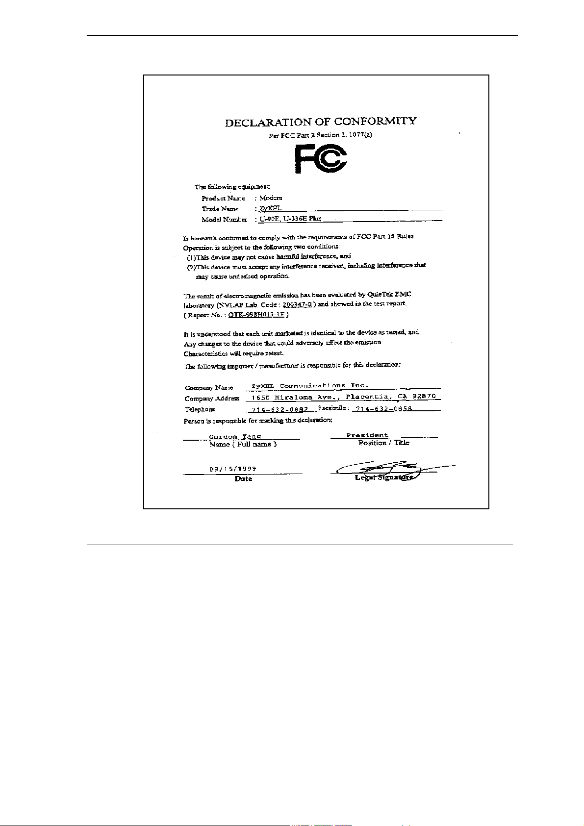
Declaration of Conformity..iii
Customer Support ............................................................................................................................v
Table of Contents.............................................................................................................................vi
List of Figures ................................................................................................................................xiii
List of Tables..................................................................................................................................xiv
Preface ...........................................................................................................................................xvii
Chapter 1 ........................................................................................................................................1-1
Getting to Know Your Modem ......................................................................................................1-1
1.1 U-336E Plus Data/Fax Modem............................................................................................1-1
1.2 Standard Features ...............................................................................................................1-1
1.3 Intelligent Features .............................................................................................................1-2
1.4 Data Compatibility................................................................................................................1-3
1.5 Fax Compatibility .................................................................................................................1-4
1.6 Technical Specifications.......................................................................................................1-4
1.7 Applications..........................................................................................................................1-5
1.7.1 Data Transfer Via Leased Line....................................................................................1-5
1.7.2 Synchronous mode DTE..............................................................................................1-6
1.7.3 Internet Access ............................................................................................................1-6
Chapter 2 ........................................................................................................................................2-1
Modem Installation ........................................................................................................................2-1
2.1 Front Panel ..........................................................................................................................2-1
2.1.1 Front Panel LEDs ........................................................................................................2-2
2.1.2 Front Panel Switches ...................................................................................................2-2
2.2 Rear Panel...........................................................................................................................2-3
vi
Page 7

U-336E Plus Data/Fax Modem
2.3 Additional Installation Requirements ...................................................................................2-4
2.4 Connecting the Modem .......................................................................................................2-5
2.5 Modem Configuration ..........................................................................................................2-5
2.6 Power On.............................................................................................................................2-6
Chapter 3 ........................................................................................................................................3-1
Setting up your Internet Connection ...........................................................................................3-1
3.1 Installing TCP/IP..................................................................................................................3-1
3.2 Configuring TCP/IP..............................................................................................................3-2
3.3 Creating a Dial-up Connection ............................................................................................3-4
Chapter 4 ........................................................................................................................................4-1
Basic Modem Operation ...............................................................................................................4-1
4.1 Understanding AT Commands.............................................................................................4-1
4.1.1 Using the Windows 95 Hyper Terminal Program .......................................................4-1
4.2 Dialing and Answering Techniques......................................................................................4-3
4.2.1 Dialing using the ATD Command............................................................................... 4-3
4.2.2 Auto-Answer and Hook Controls ................................................................................4-4
4.3 Quick Tips when issuing AT Commands .............................................................................4-4
4.3.1 Modem Result Codes ..................................................................................................4-6
4.3.2 Viewing S Register Values.......................................................................................... 4-7
4.3.3 Changing S Register Values........................................................................................4-7
4.4 Non-Volatile Memory ...........................................................................................................4-8
4.4.1 Storing Phone Numbers............................................................................................... 4-8
4.4.2 Dialing Stored Phone Numbers ...................................................................................4-8
4.4.3 Saving Settings and User Profiles ...............................................................................4-9
4.5 Helpful Hints for PC Computers ..........................................................................................4-9
vii
Page 8

U-336E Plus Data/Fax Modem
4.5.1 Default Modem Settings for PC’s..............................................................................4-10
4.6 Helpful Hints for Mac Computers.......................................................................................4-11
4.6.1 Special AT Command Settings for Mac ....................................................................4-11
4.6.2 Mac Serial Port ..........................................................................................................4-11
4.6.3 Mac Software Tips.....................................................................................................4-11
4.7 Helpful Hints for UNIX-Based Computers..........................................................................4-12
4.7.1 Serial Cable................................................................................................................4-12
4.7.2 Basic Modem Settings for UNIX ..............................................................................4-12
4.7.3 Unix Software Tips....................................................................................................4-12
Chapter 5 ........................................................................................................................................5-1
AT Command Set Summary..........................................................................................................5-1
5.1 Basic AT Command Set.......................................................................................................5-1
5.1.1 Result Code Options ....................................................................................................5-4
5.2 Extended AT& Command Set ..............................................................................................5-7
5.3 Extended AT* Command Set .............................................................................................5-14
5.4 Extended AT# Command Set ............................................................................................5-17
5.5 AT Fax Command Set........................................................................................................5-17
5.6 AT Voice Command Set.....................................................................................................5-17
Chapter 6 ........................................................................................................................................6-1
Status Registers.............................................................................................................................6-1
6.1 S-Register Descriptions .......................................................................................................6-1
6.1.1 Basic S-Registers "ATSn=x" .......................................................................................6-1
6.1.2 Extended S-Registers "ATSn=x".................................................................................6-2
Chapter 7 ........................................................................................................................................7-1
Leased Line Operation ..................................................................................................................7-1
viii
Page 9

U-336E Plus Data/Fax Modem
7.1 Connecting to a Leased Line...............................................................................................7-1
7.1.1 Line Type Setting ........................................................................................................7-1
7.1.2 Power Level Setting ....................................................................................................7-1
7.2 Leased Line Handshaking...................................................................................................7-2
7.2.1 Manual Connect ..........................................................................................................7-2
7.2.2 Auto Handshake ..........................................................................................................7-2
7.3 Terminating a Leased Line Connection ...............................................................................7-3
Chapter 8 ........................................................................................................................................8-1
Synchronous Mode Operation .....................................................................................................8-1
8.1 Mode options .......................................................................................................................8-1
8.2 Clock Options ......................................................................................................................8-2
8.3 Half-Duplex operation..........................................................................................................8-2
8.3.1 Pseudo CD...................................................................................................................8-3
8.3.2 V.13 .............................................................................................................................8-3
Chapter 9 ........................................................................................................................................9-1
Error Control and Data Compression..........................................................................................9-1
9.1 Error Control ........................................................................................................................9-1
9.2 Data Compression...............................................................................................................9-2
9.3 Flow Control.........................................................................................................................9-3
9.3.1 Hardware CTS/RTS Flow Control .............................................................................. 9-3
9.3.2 Software XON/XOFF Flow Control ...........................................................................9-3
Chapter 10 ....................................................................................................................................10-1
Special Functions........................................................................................................................10-1
10.1 Security Functions .........................................................................................................10-1
10.1.1 Levels of Security..................................................................................................10-1
ix
Page 10

U-336E Plus Data/Fax Modem
10.1.2 User Passwords......................................................................................................10-2
10.2 Remote Configuration....................................................................................................10-3
10.3 Caller Number Delivery (Caller ID) ................................................................................10-5
10.4 Distinctive Ring ..............................................................................................................10-7
10.5 Extended Distinctive Ring (EDR)...................................................................................10-9
10.5.1 Setting Up EDR ...................................................................................................10-10
10.5.2 EDR Application Example ..................................................................................10-11
10.6 On-line Help .................................................................................................................10-12
10.7 V.25bis Command Set .................................................................................................10-12
Chapter 11.....................................................................................................................................11-1
Fax Operation...............................................................................................................................11-1
11.1 Fax Basics .....................................................................................................................11-1
11.2 Modem as Fax Machine ................................................................................................11-2
11.2.1 ITU-T T.30 Fax Protocol.......................................................................................11-2
11.3 Fax Command sets........................................................................................................11-2
11.3.1 Defining the Fax Command Sets ...........................................................................11-3
11.3.2 Service Class 1 Commands ...................................................................................11-3
11.3.3 Service Class 2.0 Commands ................................................................................11-4
11.4 Status Report Result Codes ..........................................................................................11-9
Chapter 12 ....................................................................................................................................12-1
Voice Capability ...........................................................................................................................12-1
12.1 The voice AT command specification ............................................................................12-1
12.2 Voice Shield DTE command ..........................................................................................12-2
Chapter 13 ....................................................................................................................................13-1
Diagnostics...................................................................................................................................13-1
13.1 Power-on Self-test .........................................................................................................13-1
x
Page 11

U-336E Plus Data/Fax Modem
13.2 Loopback Tests..............................................................................................................13-2
13.2.1 Analog Loopback Test (AT&T1) ..........................................................................13-2
13.2.2 Analog Loopback with Self-test (AT&T8) ...........................................................13-2
13.2.3 Local Digital Loopback Test (AT&T3).................................................................13-2
13.2.4 Remote Digital Loopback Test (AT&T6) .............................................................13-3
13.2.5 Remote Digital Loopback with Self-test (AT&T7)...............................................13-3
13.3 Line Condition Report (AT#E1)......................................................................................13-3
13.4 Link Status Report (ATI2)...............................................................................................13-4
Indicator Lights ..........................................................................................................................13-7
13.4.1 Retransmission Indicator .......................................................................................13-7
13.4.2 Dialing Indicator.................................................................................................... 13-7
13.4.3 Handshaking And Retrain Indicator ......................................................................13-7
Chapter 14 ....................................................................................................................................14-1
Upgrading Your Modem ..............................................................................................................14-1
14.1 Upgrading by Flash EPROM .........................................................................................14-1
14.2 Kernel Recovery Mode ..................................................................................................14-2
Chapter 15 ....................................................................................................................................15-1
Troubleshooting ..........................................................................................................................15-1
15.1 AT Command Set Problems ..........................................................................................15-1
15.2 Command Echo Problems.............................................................................................15-3
15.3 Auto-Answer Problems..................................................................................................15-3
15.4 Dialing Problems............................................................................................................15-4
15.5 Data Transfer Problems.................................................................................................15-5
15.6 Connection Problems ....................................................................................................15-5
Appendix A....................................................................................................................................... A
xi
Page 12

U-336E Plus Data/Fax Modem
Glossary............................................................................................................................................ A
Appendix B.........................................................................................................................................I
EIA-232D Interface .............................................................................................................................I
Appendix C........................................................................................................................................J
Phone Jack Pin Assignments..........................................................................................................J
Index.................................................................................................................................................. K
xii
Page 13

U-336E Plus Data/Fax Modem
List of Figures
Figure 2-1 Front Panel ................................................................................................................................... 2-1
Figure 2-2 Rear Panel .................................................................................................................................... 2-3
Figure 3-1 Select Network Component Type................................................................................................. 3-1
Figure 3-2 Select Network Protocol............................................................................................................... 3-2
Figure 3-3 Network........................................................................................................................................ 3-3
Figure 3-4 IP Address..................................................................................................................................... 3-3
Figure 3-5 DNS Configuration....................................................................................................................... 3-4
Figure 3-6 Make New Connection................................................................................................................. 3-5
Figure 3-7 Insert ISP’s Phone Number .......................................................................................................... 3-5
Figure 3-8 Completing Dial-Up Connection.................................................................................................. 3-6
xiii
Page 14

U-336E Plus Data/Fax Modem
List of Tables
Table 1-1U-336E Plus Data Operation Modes................................................................................................1-3
Table 1-2 Fax Compatibility ..........................................................................................................................1-4
Table 2-1 LED Indicators ...............................................................................................................................2-2
Table 2-2 Front Panel Switches ......................................................................................................................2-3
Table 2-3 Rear Panel.......................................................................................................................................2-4
Table 4-1 Modem Settings..............................................................................................................................4-2
Table 4-2 AT Result Codes .............................................................................................................................4-5
Table 4-3 Basic Commands ............................................................................................................................4-5
Table 4-4 AT Command Sets/Types................................................................................................................4-6
Table 4-5 Profile Setting Commands..............................................................................................................4-9
Table 4-6 Default Settings ............................................................................................................................4-10
Table 5-1 Basic AT Command Set..................................................................................................................5-1
Table 5-2 Result Code Options.......................................................................................................................5-4
Table 5-3 Extended AT& Command Set.........................................................................................................5-7
Table 5-4 Extended AT* Command Set........................................................................................................5-14
Table 5-5 Extended AT# Command Set........................................................................................................5-17
Table 6-1 Basic S-Registers............................................................................................................................6-1
Table 6-2 Extended S-Registers......................................................................................................................6-2
Table 7-1 AT Command to Set Line Type.......................................................................................................7-1
Table 7-2 AT Command to Set Power Level...................................................................................................7-1
Table 7-3 AT Command for Auto Handshake .................................................................................................7-2
Table 8-1 Synchronous Mode Options............................................................................................................8-1
Table 8-2 Clock Options.................................................................................................................................8-2
Table 9-1 Error Control and Data Compression .............................................................................................9-2
xiv
Page 15

U-336E Plus Data/Fax Modem
xv
Table 10-1 Security Function Commands.................................................................................................... 10-3
Table 10-2 AT*Rab Command..................................................................................................................... 10-4
Table 10-3 AT*Wab Command .................................................................................................................... 10-4
Table 10-4 Ring Control............................................................................................................................... 10-8
Table 10-5 EDR Settings............................................................................................................................ 10-10
Table 10-6 V.25 Command Set................................................................................................................... 10-12
Table 11-1 Service Class 1 Commands .........................................................................................................11-3
Table 11-2 MOD Parameters.........................................................................................................................11-4
Table 11-3 Service Class 2.0 Commands ......................................................................................................11-4
Table 11-4 Status Report Result Codes .........................................................................................................11-9
Table 12-1 Voice AT Commands.................................................................................................................. 12-1
Table 12-2 Voice Shield DTE Command..................................................................................................... 12-2
Table 13-1 Data Type Description................................................................................................................ 13-4
Table 13-2 Output Value Description........................................................................................................... 13-4
Page 16

Page 17

U-336E Plus Data/Fax Modem
Preface
About Your Modem
Congratulations on the purchase of yourU-336E Plus modem - one of ZyXEL's premier highperformance products. TheU-336E Plus modem is world renown for its ability to maintain ultra
high speeds and clear, quality connections while communicating around the globe.
About This Manual
This manual describes the use of yourU-336E Plus data/fax modem and gives instruction for its
installation and operation.
Structure of this Guide
This manual is divided into four sections:
• Getting Started (Chapters 1-4) gives a basic overview of your modem’s features, explains its
installation procedures and introduces you to the basic commands and techniques involved in
modem operation.
• Settings and Commands (Chapters 5-6) provides an overview of the settings and commands
which are available in theU-336E Plus modem.
• Additional Functions (Chapters 7-13) describes many special functions and features of theU-
336E Plus modem in detail, including error control and data compression, leased-line and
synchronous mode operation, remote configuration, caller ID, fax sending and receiving, voice
mail and diagnostic features.
• Upgrading and Troubleshooting (Chapters 14-15) provides information about upgrading your
modem and solving common problems.
Becoming a Registered Owner
xvii
Page 18

U-336E Plus Data/Fax Modem
Complete the pre-addressed Warranty Registration Card and place it in the mail. Registered owners
will receive future product information and update announcements. Warranty registration is not
necessary for product repair/or replacement. Save your dated invoice as proof of purchase.
xviii
Page 19

U-336E Plus Data/Fax Modem
Chapter 1
Getting to Know Your Modem
This chapter describes the key features and applications of your 56/33.6 Kbps Data/Fax modem.
1.1 U-336E Plus Data/Fax Modem
The U- 336E Plus is an analog Data/Fax modem used for data transmission via PSTN line. It
connects to both 2-wire dial-up and 2-wire leased line. The synchronous transmission mode can
support up to 33.6kbps. For Internet access application, it operates with downstream maximum
speed of up to 56Kbps and upstream speed of up to 33.6Kbps. The speed depends on the line
quality, and server side configuration.
1.2 Standard Features
• ITU V.90 56Kbps down-stream data transmission.
• V.34bis 33.6Kbps data transmission rate.
• Operates in all system environments including Windows 95, DOS, Windows, Macintosh, OS/2,
UNIX, Novell, Amiga, and IBM AS400/RS6000 and other synchronous mode DTE.
• Microsoft Windows 95/98/NT plug and play compatible.
• V.42 and MNP 4/3 error control.
Getting to know your Modem
1-1
Page 20

U-336E Plus Data/Fax Modem
• V.42bis and MNP 5 data compression.
• DTE serial interface with speeds up to 460.8Kbps.
• 12 LED indicators.
• Extended AT command set.
• V.25bis command set..
• Operates on 2-wire dial-up or 2-wire leased line.
• On-line help for easy command reference.
1.3 Intelligent Features
• Automatic data and voice call detection allows you to use a single telephone line to handle both
types of calls.
• Asynchronous and synchronous modes for reliable serial data communication. Up to 33.6 Kbps
for synchronous transmission.
• Fast retrain with automatic fall-forward and fall-back. Your modem will automatically fall
back to lower speeds when communicating with slower modems and when encountering
unstable or variable line conditions.
• Call-back security and password protection restricts access to authorized callers only.
• Caller ID identifies incoming calls before you answer (you must subscribe to this service
through your telephone company in order for your modem to identify callers).
• Distinctive ring detects data and voice calls (this feature requires communication software that
supports distinctive ring, such as ZFAX).
1-2 Getting to know your Modem
Page 21
U-336E Plus Data/Fax Modem
• Remote configuration capability.
• EDR (extended Distinctive Ring).
• Flash EPROM memory lets you easily upload new firmware, providing you with easy access to
new features.
• ZyXEL exclusive Kernel Recovery Mode for no hassle recovery from failed flash uploads - no
factory repairs needed.
• Reduced voice function. Supports DTMF tone generation and detection only.
1.4 Data Compatibility
TheU-336E Plus modem is a high performance universal modem capable of transmission speed up
to 56/33.6 Kbps full-duplex on a 2-wire dial-up line. Universal compatibility covers a broad range
of ITU-T and BELL standards.
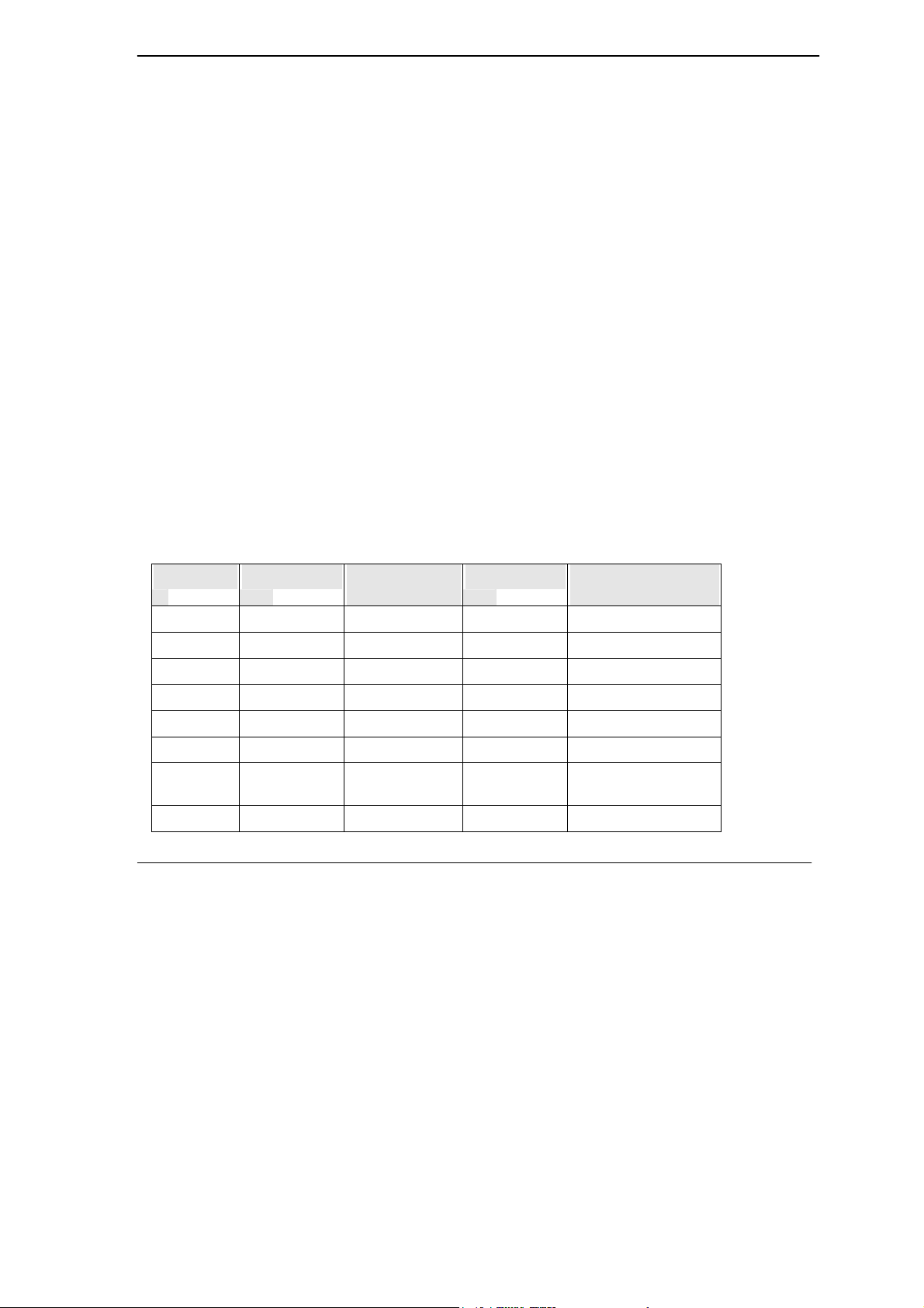
Various operation modes that can be achieved are as follows:
Table 1-1U-336E Plus Data Operation Modes
Standard Bit Rate [bps] Baud Rate
[baud]
V.90 28000-56000 8000 PCM
V.34bis/V.34 33600-2400 multiple TCM multiple
V.32bis 14400 2400 128-TCM 1800
V.32bis 12000 2400 64-TCM 1800
V.32bis 7200 2400 16-TCM 1800
V.32 9600 2400 32-TCM 1800
V.32
uncoded
V.32 4800 2400 4-DPSK 1800
Getting to know your Modem
9600 2400 16-QAM 1800
Modulation Carrier Frequency
[Hz]
1-3
Page 22

U-336E Plus Data/Fax Modem
V.23 1200/75 1200/75 FSK
V.23 600/75 600/75 FSK
V.22bis 2400 600 16-QAM 1200 Org
2400 Ans
V.22
(BELL 212A)
V.21 300 300 FSK
BELL 103 300 300 FSK
1200 600 4-DPSK 1200 Org
2400 Ans
1.5 Fax Compatibility
TheU-336E Plus modem supports fax applications and is compatible with many fax transmission
standards. It provides the highest fax speed of up to 14400 bps using the fax transmission standard
V.17.
Table 1-2 Fax Compatibility
Standard Bit Rate [bps] Baud Rate [baud] Modulation Carrier Frequency [Hz]
V.17 14400-7200 2400 TCM 1800
V.29 9600-4800 2400 QAM/DPSK 1700
V.27ter 4800-2400 1600/1200 PSK/DPSK 1800
V.21 300 300 FSK
1.6 Technical Specifications
• Operating mode: auto-dial/answer.
• Flow control: software XON/XOFF or hardware CTS/RTS.
1-4 Getting to know your Modem
Page 23

U-336E Plus Data/Fax Modem
• Data/Voice toggle switch.
• Configuration settings: software programmable with non-volatile memory for phone
number/profile storage.
• Diagnostics: self-test, analog loopback (with self-test), digital loopback, and remote digital
loopback (with self-test).
• Dialing type: tone/pulse dialing.
• Line interface: 2-wire dial-up or 2-wire leased line.
• Call progress monitoring dial tone, busy, and ring back detection.
• Audio Monitor: programmable volume control.
1.7 Applications
1.7.1 Data Transfer Via Leased Line
YourU-336E Plus modem provides reliable transmission quality on-line data transfer for users
subscribing a leased line. It is useful for networks that have traffic requirements with steady and
sustained patterns, such as large file transfers. Your modem is a cost-effective way to handle a
high volume of data and/or voice traffic.
Leased lines are very popular method of connecting corporate sites. They are essentially private
reserved pathways (or pipelines). The private nature of the leased line networks provides inherent
privacy and control benefits. Digital leased lines provide good line quality. For more information
please read the chapter Leased Line Operation
Getting to know your Modem
1-5
Page 24

U-336E Plus Data/Fax Modem
1.7.2 Synchronous mode DTE
YourU-336E Plus modem provides service on an immediate basis and ensures a steady flow of data.
It is very useful for users using synchronous mode DTE like IBM mainframes.
To process large amount of information, you can use theU-336E Plus to transmit data to remote
synchronous DTEs with speed of up to 33.6Kbps. For more information please read the chapter
Synchronous Mode Operation.
1.7.3 Internet Access
YourU-336E Plus modem supporting the V.90 protocol is the ideal choice for high-speed access to
the Internet.
V.90 technology is ideal for Internet users, because it enables fast downloading of Web pages with
sound, video and other large files.
Your modem is compatible with ISP servers having modem chipsets manufactured by major
vendors such as Rockwell, Lucent and U.S Robotics.
For more information on setting up your modem for Internet connection refer to the chapter Setting
up your Internet Connection.
1-6 Getting to know your Modem
Page 25
U-336E Plus Data/Fax Modem
ZyXEL
Chapter 2
Modem Installation
This chapter describes the panel function and installation procedure for the U-336E PLUS.
A shielded RS-232 cable is required to ensure compliance with FCC Part 15, and it is your
responsibility to use a shielded RS-232 cable. Make sure your installation site is clean and well
ventilated. The ventilation slot of your ZyXEL modem located on the sides and bottom should not
be covered to allow for free movement of air.
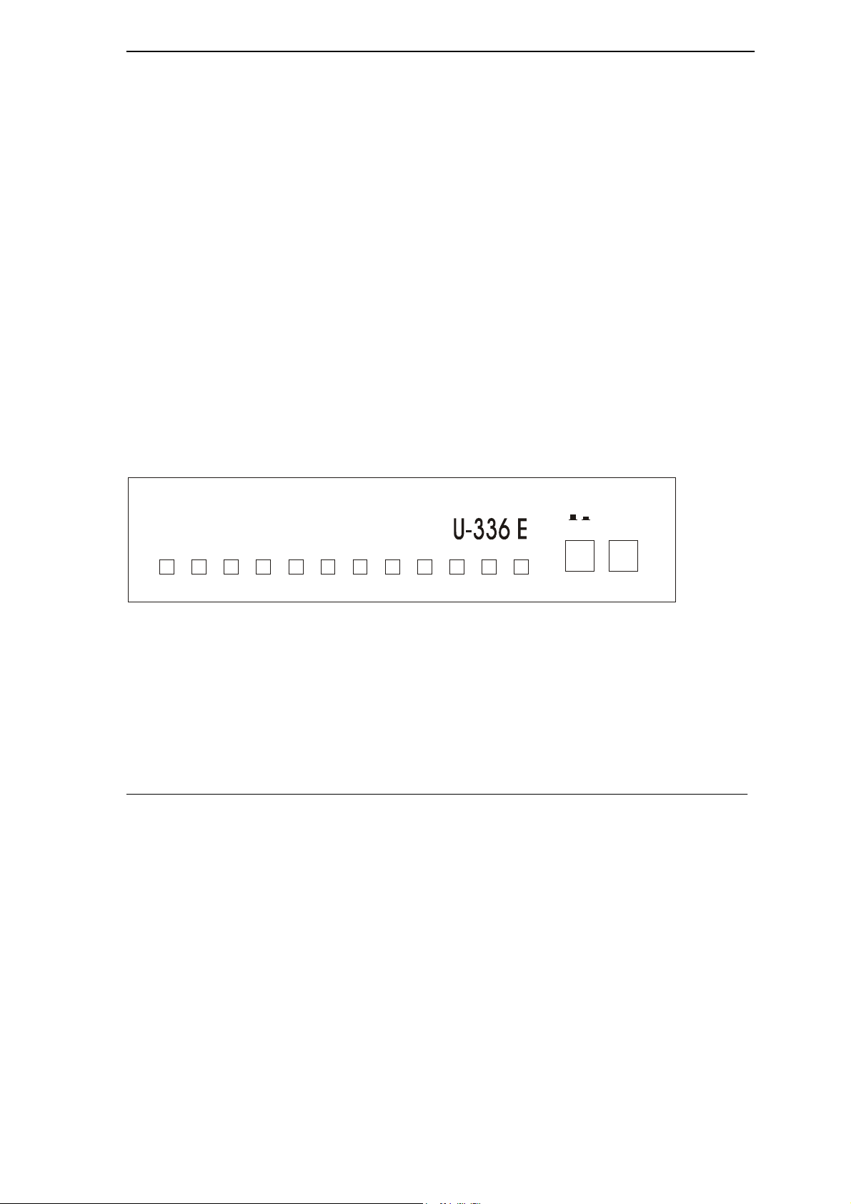
2.1 Front Panel
The LEDS on the front panel indicate the operational status of the modem. Figure 2.1 shows the
front panel of theU-336E Plus. There are 12 LED indicators and two key switches.
H S
H SH S
A AA A
C DC D
O HO H
O HC D
C DAA
A AH S
Modem Installation
D TRO H
D TRD TR
V 90 / V 34 / FAX
V 90 / V 34 / FAX
V 90 / V 34 / FAX V 90 / V 34 / FAX
C TS RTS
D SRD TR
C TSC TS
D SRD SR
Figure 2-1 Front Panel
RTSD SR
RTSRTS
TX D R XD
RXDC TS
TX DTX D
RXDRXD
SQ
SQ TST
TSTTX D
SQSQ
TSTTST
Plus
A /O
A /O
A /OA /O
/
D /V
D /V
D /VD /V
2-1
Page 26

U-336E Plus Data/Fax Modem
2.1.1 Front Panel LEDs
The following table describes the LED indicators.
Table 2-1 LED Indicators
LEDs Description
HS High Speed mode indicator, lights ON when your modem is operating in V.34 or V.90
mode; flashes when your modem is in Handshaking State.
AA Auto-Answer indicator lights ON when your modem is in the Auto Answer Mode; and
Flashes when modem rings. In error control mode, it flashes when retransmitting.
CD Carrier Detect indicator, lights ON when a valid carrier is detected present on the line.
OH Off-Hook indicator lights ON when your modem is in data mode or off-hook and lights
OFF when your modem is in talk mode or on-hook.
DTR Data Terminal Ready indicator, lights ON when your DTE or computer indicates that it
is ready to begin communication and lights OFF when DTE is not ready to transmit
data.
DSR DTE mode. Data Set Ready Indicator, lights ON when the modem is ready for
communication and lights OFF when the modem is not ready.
CTS DTE mode. Clear To Send indicator, lights ON when modem can accept data for
transmission. It indicates the signal status of RS232 signal CTS.
RTS DTE mode. Request To Send indicator, indicates the signal status of RS232 signal
RTS from DTE. RTS is used for hardware flow control in asynchronous data
transmission.
TXD Transmit indicator, ON when your DTE/computer transmits data on the serial port.
RXD Receive indicator, ON when your DTE/computer receives data on the serial port.
SQ Signal Quality Indicator, ON when signal quality is good, OFF when signal quality is
bad, and flashes when signal quality is marginal or during power up to indicate an
error condition.
TST Test indicator, ON when modem is in the test mode.
2.1.2 Front Panel Switches
The following table describes the Front Panel Switches:
2-2
Modem Installation
Page 27
U-336E Plus Data/Fax Modem
Table 2-2 Front Panel Switches
Switches Description
A/O Pressing the button will set the modem in originate mode and releasing it in answer
mode.
This switch only determines modem operation if the modem is made to go off-hook
manually. Or else the ATD or ATA command will automatically determine the
mode.
D/V Switches the modem into data mode or voice mode. (the telephone is connected to
the line).
Warning: If the A/O switch is pressed while the modem is being turned on; the modem will jump
into a special kernel program that allows you to upload new firmware into the modem from a
computer. If this is not what you intended, turn off the modem and then turn it on again to return to
normal operation.
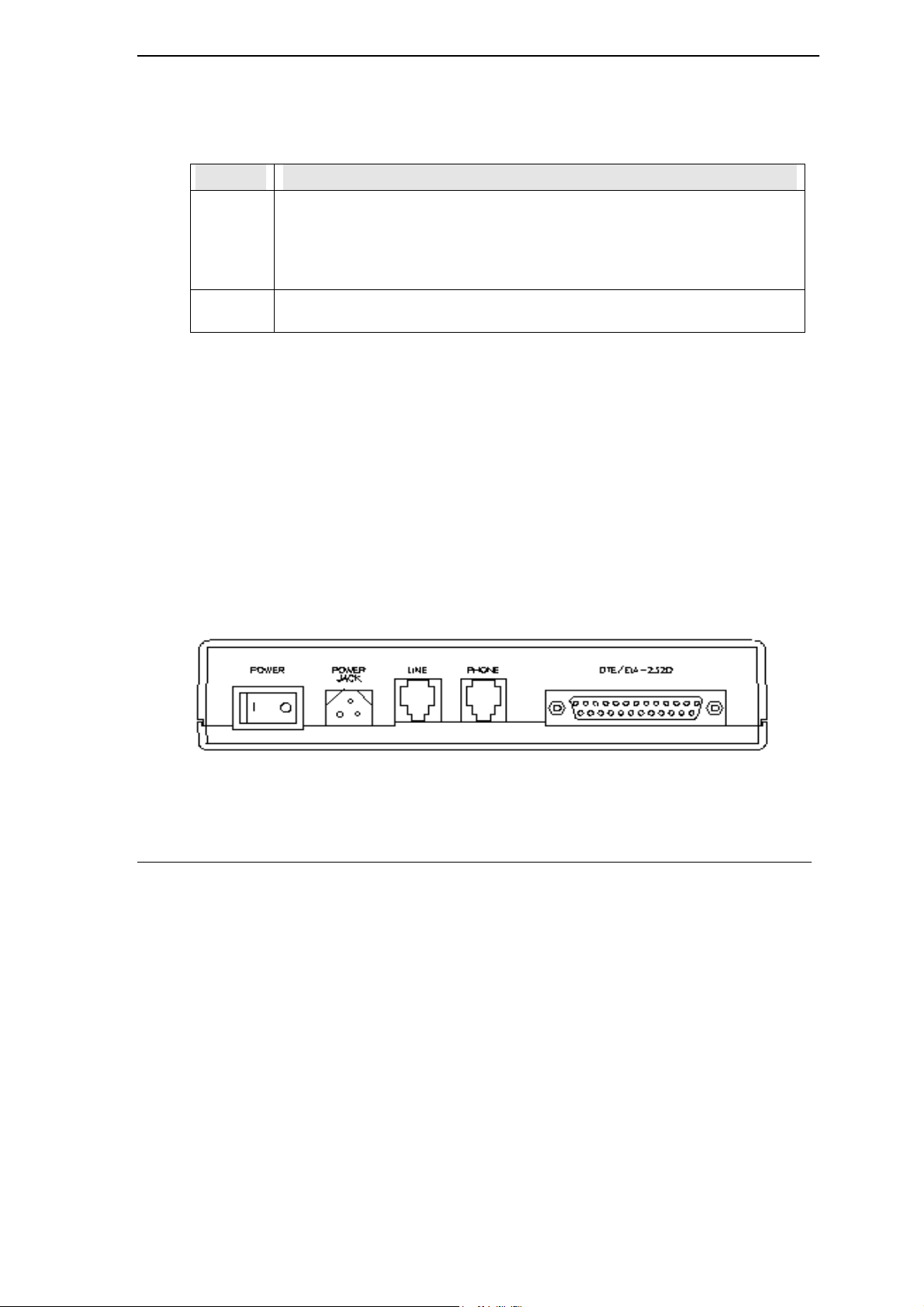
2.2 Rear Panel
TheU-336E Plus rear panel is shown below:
Figure 2-2 Rear Panel
Modem Installation
2-3
Page 28
U-336E Plus Data/Fax Modem
Table 2-3 Rear Panel
Printed on
U-90E Housing
Power Power switch, turns the modem ON or OFF.
Power Jack Input terminal for power adapter.
Line Dial-up line RJ-11 terminal jack, for connection to a 2-wire dial-up or 2-wire leased line.
Phone RJ-11 terminal jack, for connection to a telephone set. Pin assignments for RJ-11 phone
DTE/EIA 232D Serial port DB25F connector, for connection to the serial port of a DTE (computer
Description
jacks are listed in the Appendix.
terminal). Pin assignments of the DTE are listed in the Appendix.
2.3 Additional Installation Requirements
• In addition to the ZyXEL modem you just purchased, you must have the following equipment
to operate your modem:
• Computer terminal.
• Available PC serial port with a high-speed 16550 UART.
• Standard "straight-through” RS-232 cable (pins 1-8, 20, and 22).
• Available telephone jack.
• Available AC wall outlet.
2-4
Modem Installation
Page 29

U-336E Plus Data/Fax Modem
• Telephone line from your telephone company (dial-up or leased line).
• Data and fax communication software.
2.4 Connecting the Modem
Connect the power plug from the adapter to the power jack and plug the other end into an electrical
outlet. When you connect your modem to the power line, make sure you only use the power
adapter that is supplied with this unit. Use of another adapter may not allow your modem to operate
and could result in serious damage to the unit.
This adapter is rated for direct connection to an AC power outlet.
Turn off the power on both the computer and the modem before making connections. Then connect
the modem according to the rear panel labels.
Note: Before using RS-232 to connect your modem to your PC, please find the COM port on the
back of your PC to determine the pin type of the required connector.
2.5 Modem Configuration
There are no DIP (dual in-line package) switches or configuration settings that you need to worry
about. Your modem is factory pre-set. User configurations are also conveniently stored in user
selectable non-volatile memories and can be recalled as often as needed by using ATZn command.
Modem Installation
2-5
Page 30

U-336E Plus Data/Fax Modem
2.6 Power On
Once your modem’s power switch is turned ON, a series of diagnostic tests will be performed. For
a more detailed description of these diagnostic tests, please refer to the chapter on Diagnostics and
Troubleshooting. After performing the diagnostic tests, your modem is ready for use.
2-6
Modem Installation
Page 31

U-336E Plus Data/Fax Modem
Chapter 3
Setting up your Internet Connection
For accessing Internet, you must install TCP/IP in your computer, configure the TCP/IP, and then
create a PPP connection.
3.1 Installing TCP/IP
If TCP/IP is already installed in your computer, you may go to the next section about configuring
the TCP/IP; if not, from Start, select Settings/Control Panel, then click on Network. Then click
Add and you will see the following screen:
Figure 3-1 Select Network Component Type
Select Protocol, then click on Add.
Setting up your Internet Connection
3-1
Page 32

U-336E Plus Data/Fax Modem
You will see Figure 3-2 Select Network Protocol.
Figure 3-2 Select Network Protocol
Select Microsoft and TCP/IP, then click on OK.
3.2 Configuring TCP/IP
If your TCP/IP is already configured, you may go to the next section to setup a PPP connection; if
not, follow the steps below:
From Start, select Settings/Control Panel, then double-click on Network.
3-2
Modem Installation
Page 33

U-336E Plus Data/Fax Modem
Figure 3-3 Network
Select TCP/IP, then click Properties. You will see the following screen.
Figure 3-4 IP Address
In most cases, you have to select Obtain an IP address. If you have an assigned IP address from
your ISP, select Specify an IP address then enter your IP address and subnet mask. Then click on
DNS Configuration.
You will see the following screen. Select Enable DNS, enter your Host name, Domain name, and
the DNS of your ISP, then click on OK.
Setting up your Internet Connection
3-3
Page 34

U-336E Plus Data/Fax Modem
Figure 3-5 DNS Configuration
3.3 Creating a Dial-up Connection
At this point, you are only one step away from accessing the Internet. Follow the instructions
below to create a new dial-up connection.
Click on My Computer on your desktop, select Dial-up Networking, then click on Make New
Connection.
3-4
Modem Installation
Page 35

U-336E Plus Data/Fax Modem
Figure 3-6 Make New Connection
Give a name to this Dial-up Connection. For example,U-336E Plus. Then select your new modem
as the device to connect to Internet, and then click Next. You will see the following screen.
Figure 3-7 Insert ISP’s Phone Number
Setting up your Internet Connection
3-5
Page 36

U-336E Plus Data/Fax Modem
Enter your ISP's phone number, and then click Next.
Figure 3-8 Completing Dial-Up Connection
Click Finish.
Now, you have completed dial-up setup. From now on, you can access the Internet by your new
device.
3-6
Modem Installation
Page 37

U-336E Plus Data/Fax Modem
Chapter 4
Basic Modem Operation
This chapter covers the basic commands and techniques involved in modem operation. In many
cases, this is the only information you will need in order to use the communication software, and to
start making connections with your modem.
4.1 Understanding AT Commands
TheU-336E Plus communicates asynchronously with computers using AT commands. AT
commands are used to configure and control your modem. Commands are usually sent to the
modem by way of communication software, but can also be entered manually by the user with the
computer keyboard.
Command statements must be written in a specific form for your modem to recognize them. A
command statement always begins with the letters AT or at. One or more commands and the
<Enter> key then follow it.
AT commands can only be issued when your modem is in “command mode” or “off-line.”
Once your modem has established a connection with another modem it is said to be “on-line” or in
“data mode.” In this mode, the characters sent to your modem by your computer are transmitted to
the remote modem rather than being interpreted by your modem as commands.
4.1.1 Using the Windows 95 Hyper Terminal Program
In order to issue an AT command statement, you first need to run a communication program such
as the Microsoft Windows “Hyper Terminal” program. This program provides a simple method to
manually enter AT commands so you can do such things as “customize” the settings of your
modem, or store commonly used phone numbers.
Basic Modem Operation
4-1
Page 38

U-336E Plus Data/Fax Modem
Once your modem is connected to your computer’s serial port and telephone line, open the
Windows 95 “Accessories” program group, and open the Hyper Terminal Program.
The program will prompt you for a name and Icon to use for your new connection. Type the name
Test Connection and press <Enter>.
Next, you will be prompted for country information, area code and phone number, and the device
used to make the connection. For this test purpose, do not enter a phone number; simply choose the
COM port your modem is connected to from the “Connect Using” list. Click “OK” when finished.
The next window sets the COM port settings. The settings used for your modem should be as
follows.
Table 4-1 Modem Settings
Bits per second: 57600
Data bits: 8
Parity: None
Stop bits: 1
Flow Control: Hardware
Click “OK” when finished. After you have done this, save your new connection by selecting
“Save” from the “File” menu and click “OK.” A new connection icon will be added to your Hyper
Terminal folder.
You are now ready to start entering AT commands.
In the terminal window, type:
AT<Enter>
Your modem responds
OK
This confirms that the modem and your computer are communicating correctly.
4-2
Basic Modem Operation
Page 39

U-336E Plus Data/Fax Modem
To test the telephone line connection issue the manual answer command.
Type:
ATA<Enter>
Your modem will pick up the phone line, and try to communicate. Normally, this command is only
used to answer an incoming call made from another modem, thus the high pitched tone you will
hear from the speaker. To abort the operation, press any key, or select “Disconnect” from the
“Call” menu.
4.2 Dialing and Answering Techniques
Depending on what communications software you use to make modem connections, you may not
have as much control of how the modem dials the telephone number. This section shows some
useful examples of the AT commands used for dialing and answering operations. The command
characters specific to each function are shown in bold type.
4.2.1 Dialing using the ATD Command
Touch Tone Dialing: ATDT 555 1212
Pulse Dialing: ATDP 555 1212
Tone and Pulse Dialing: ATDP 555 1212 WT 24
Dialing Through a PBX: ATDT 9 W 555 1212
NOTE: The 'W' in the dial string will cause the modem to wait for a second dial tone before it
continues to dial.
Pausing During Dialing: ATDT 9,,555 1212
NOTE: The pause time for each comma is defined by S Register S8. Default is 2 seconds per
comma.
Dialing Without Waiting for Dial Tone: ATX0D, 555 1212
Originating a call using an Answer Tone: ATDT 555 1212,,,,,,R
Basic Modem Operation
4-3
Page 40

U-336E Plus Data/Fax Modem
Redialing the Last Number Called: ATDL
Waiting for Five Seconds of Silence: ATDT 800 555 1212 @
123456,1 714 555 1212
Transferring a Call (using flash hook): ATDT! 2468
4.2.2 Auto-Answer and Hook Controls
Enabling Auto-Answer: ATS0=n
NOTE: In this example, n is a number from 1 to 255 that corresponds to the number of rings after
which your modem answers an incoming call.
Disabling Auto-Answer: ATS0=0
Manually Answering a Call: ATA
Take modem off-hook: ATH1
Hang up modem (on-hook): ATH0
4.3 Quick Tips when issuing AT Commands
The ENTER or RETURN key must be pressed to execute a command.
Multiple AT commands can be combined into one line. For example, AT&D2 and AT&N0 can be
combined into one line AT&D2&N0.
Your modem processes commands from left to right. The AT command that appears to the right
might over-write the command to the left if they are trying to accomplish tasks or set modes that
could not coexist.
If you see duplicated characters for each character you type, your modem and software both have
their “echo” feature turned on. The modem command echo state is switched off using ATE0 and
on using ATE1 (default). To eliminate the double characters, turn off the software’s command
4-4
Basic Modem Operation
Page 41

U-336E Plus Data/Fax Modem
echo rather than using the ATE0 command. If you see no characters in your terminal window
when you type, the modem’s echo setting is probably set to off. In this case, issue the ATE1
command.
When a command is successfully issued and accepted, a modem responds with a “Result Code.”
Your modem supports both “verbose” result codes and “numerical” result codes (i.e. “0”). You can
use the ATV command to set it one way or the other as follows.
Table 4-2 AT Result Codes
Command Description
ATV0 Select numerical result code.
ATV1 Select verbose result code.
There are a few basic commands that do not require the “AT” command prefix. They are as follows:
Table 4-3 Basic Commands
Command Description
A/ Repeats the last issued AT command once.
A> Repeats the last issued AT command once, or re-
dials the last dialed number up to 9 times until a key
is pressed or a connection is made.
<any key> Terminates the current connection attempt, if pressed
while modem is handshaking.
+++ Escape code sequence. Entered while the modem is
in Data Mode. Returns modem to Command Mode.
TheU-336E Plus supports several groups of AT commands:
Basic Modem Operation
4-5
Page 42

U-336E Plus Data/Fax Modem
Table 4-4 AT Command Sets/Types
AT Command Set/Type Example
Basic AT (Hayes compatible) ATB0
Extended AT& commands AT&N0
Extended AT* commands AT*I1
Fax AT+ commands AT+FCLASS=2
S-Register command ATS0=1
S-Register bit-mapped
command (set S-Register bit
1 equal to 1)
S-Register inquiry command ATS0? Or ATS13.1?
ATS13.1=1
You may browse the lists of available commands for each command set by using the on-line help
commands: AT$(for Basic AT command set), AT*$ (for AT* command set), and AT&$
(for AT& command set). For more information on AT commands refer to chapter AT Command
Set Summaries.
4.3.1 Modem Result Codes
When you execute or try to execute an AT command, your modem sends a result code to let you
know whether the command was executed. An OK result code means that the AT command you
sent was executed. If you receive an ERROR code, it means the command was invalid.
TheU-336E Plus also provides result codes that show:
Whether or not a Dial Tone was detected when the modem originated a call.
Whether a busy signal was detected when the modem originated a call.
If a remote telephone ring was detected when dialing.
The speed, protocol, and error control/data compression method used.
4-6
Basic Modem Operation
Page 43

U-336E Plus Data/Fax Modem
If an incoming ring was detected.
Result codes can originate from any of eight result code sets. The ATXn command lets you choose
which set of result codes your modem can use. By default, your modem uses result codes
equivalent to the ATX5 command.
For more information on result code options refer to the chapter AT Command Set Summaries.
4.3.2 Viewing S Register Values
Status registers (or "S-registers") contain values that determine the modem’s operating
characteristics. Whenever you send an AT command to your modem, you are actually changing
the value of an S-register.
You can use the Sr? command to view the value of S-register ‘r’. For example, to view the value
of S-register S0, which controls auto-answering, type ATS0? and press Enter. The modem
responds with a three-digit character showing the value of this register, followed by OK. A value of
002, for example, means your modem will auto-answer incoming calls after the second ring.
Some S-registers are bit mapped. For these registers, you can use the Sr.b? command to read their
values.
For example, to read the value of S-register S35, bit 7, type ATS35.7? and press Enter. The
modem responds with an appropriate value, followed by OK. For more information on S-registers
refer to the chapter Status Registers.
4.3.3 Changing S Register Values
You can use the ATS0=n command to change the value of an S-register.
For example, to have your modem auto-answer an incoming call after two rings, set S-register 0 to
2. Be sure the n value is between 1 and 255. If n is set to 0, your modem will not answer incoming
calls.
Basic Modem Operation
4-7
Page 44

U-336E Plus Data/Fax Modem
4.4 Non-Volatile Memory
TheU-336E Plus has an amount of memory set aside for storing user information such as frequently
used phone numbers and default command settings. The latter is particularly useful when using
your modem to call a variety of different locations that require different settings. For this reason,
your modem provides a number of user “Profiles” that can be accessed through simple AT
commands. This section gives information about storing phone numbers, and saving default
settings in the power-on profile.
4.4.1 Storing Phone Numbers
The AT command to store a phone number is in the format AT&Zs=n.
The ‘s’ is a number from 0 to 49 that represents the location in memory where the phone number
can be stored, and the ‘n’ is the phone number itself.
Example: To store the number ‘1-714-555-1212’ in memory location ‘2’, type:
AT&Z2=17145551212<Enter>
You can store up to 50 telephone numbers.
4.4.2 Dialing Stored Phone Numbers
The AT command syntax used to dial a stored number is ATDS=n.
The ‘n’ is the memory location of the stored number you want to dial.
NOTE: As a general rule, when a letter in an AT command definition is shown in italic type, the
letter is not to be entered as part of the command, but rather is representative of a number or string
expected as input. For example: The letter ‘S’ in the ATDS=n command is actually typed, unlike
the ‘s’ in the AT&Zs=n command which represents a number.
4-8
Basic Modem Operation
Page 45

U-336E Plus Data/Fax Modem
4.4.3 Saving Settings and User Profiles
There are some cases where you may wish to save the settings you have made as the default
settings that are recalled when your modem is powered up. The AT&WZ command selects the
current settings as the power-on profile.
There are four profiles that can be changed by the user, and one factory default profile.
Profiles 0 to 3: User profiles.
Profile 4: Factory default profile.
The following table lists the syntax for the commands involved in storing, recalling, and viewing
profile settings:
Table 4-5 Profile Setting Commands
Command Description
AT&Vn Views the settings in profile (n-1); n=0 to 5; n=0 views current
settings.
AT&Wn Stores the current settings in user profile ‘n’; n=0 to 3.
ATZn Resets the current settings with the settings in profile ‘n’, n=0 to 4.
4.5 Helpful Hints for PC Computers
Most PCs are equipped with more than one serial port. Standard cables are readily available from
many suppliers. Usually, serial ports are manufactured in two forms, either with a 25-pin male jack
or a 9-pin male jack. For high speed serial connections at 230.4Kbps or 460.8Kbps, use a lowcapacitance cable. Also, keep the cable as short as possible.
Basic Modem Operation
4-9
Page 46

U-336E Plus Data/Fax Modem
The serial port is driven by interrupts. Every interrupt needs a certain amount of overhead
processing time. Too many interrupts reduce the computer's efficiency. The UART 16450 is very
commonly used in serial port devices. For every character (byte) received, it generates an interrupt.
If your hardware allows it and if your software supports it, replace the 16450 UART with a 16550
model. This newer chip has an internal buffer and generates an interrupt for up to every 16
characters (several trigger levels are available). With this UART installed, you may drive your
serial port at 57600 bps and above.
While data is written from the transfer-buffer to your hard-disk, characters may be lost at the serial
port. This is due to the fact that disk-access interrupts have a higher priority than serial port
interrupts. If you are running at a high serial speed, e.g. 230.4Kbps or 460.8Kbps, on your PC, be
sure to enable the disk cache by including SMARTDRV execution in your AUTOEXEC batch file.
4.5.1 Default Modem Settings for PC’s
TheU-336E Plus factory settings are configured for operation with PC type computers and
communication software. In most cases, no additional settings will be required. The following are
some of the default settings that are used for operation with PC computers and software:
AT Command Description
E1 Echoes command characters.
&C1 Carrier detect follows remote carrier.
&D2 Modem disconnects on DTR on-to-off transition.
&K4 Uses both V.42 and MNP 4 error correction, and V.42bis
and MNP 5 data compression.
&N0 Modem negotiates highest possible connection speed.
Table 4-6 Default Settings
4-10
Basic Modem Operation
Page 47

U-336E Plus Data/Fax Modem
4.6 Helpful Hints for Mac Computers
4.6.1 Special AT Command Settings for Mac
For operation with Mac computers, you may use the factory default settings with one exception.
You must set the modem to ignore the DTR signal as follows.
Type:
AT&D0<enter> (set modem to ignore DTR)
AT&WZ<enter> (saves the settings to power-up profile)
4.6.2 Mac Serial Port
When you connect your modem to a Macintosh computer, make sure the cable is a hardware
handshaking type. These cables are readily available. Macintosh Lisa model 128 and 512 don't
have hardware handshaking. The serial port on these (very outdated) models is provided as a 9-pin
connector similar to that of a PC. The serial port on all other Macintosh models is a Mini-8.
4.6.3 Mac Software Tips
All terminal programs that make use of the hardware handshaking feature can be used on the Apple
Macintosh. Such programs are readily available as PD, shareware or commercial software. One of
the most powerful shareware programs available is ZTerm.
Fewer programs are available to make use of the ZyXEL's fax features. One program that has
found wide acceptance is FaxSTF that can be installed like a printer driver allowing you to send
faxes from almost any program which runs on your Macintosh. At the same time it allows
automatic fax receiving. This program includes powerful line manager software which makes sure
fax software does not interfere with other programs using the serial ports. If the modem is turned
off when you start your Macintosh with the line manager activated, the computer may seem to
freeze for a few minutes. During this time the line manager software tries to locate and to set up the
modem. Turn on your modem before you start your Macintosh to avoid this delay.
Basic Modem Operation
4-11
Page 48

U-336E Plus Data/Fax Modem
MaxFax is another fax software for Macintosh computers.
Drivers are available which allow use of the serial ports at speeds up to 230.4 Kbps. These drivers
are currently available for Power Macs and AV Macs only.
4.7 Helpful Hints for UNIX-Based Computers
4.7.1 Serial Cable
Please consult the documentation that came with your workstation to find the part number of or
information on how to make a serial cable for your workstation. The cable should be a hardwarehandshaking type. Please refer to Appendix for a complete list of signals provided for the modem’s
serial port.
4.7.2 Basic Modem Settings for UNIX
Unix environments usually don’t like modem responses or echoing of commands. Therefore you
should set ATE0Q1.
Depending on your Unix setup, the cable and software used, you may have to disable carrier
detection using AT&C0.
4.7.3 Unix Software Tips
In order to use your ZyXEL modem from a terminal or an X-Windows application, you need a
program such as Minicom or Seyon.
If you wish to make use of your ZyXEL modem's special features, special gettys such as mgetty or
vgetty are needed. These programs are available from several ftp-sites. Some archives also contain
source files.
You should suppress the modem's result code to (ATQ1) because they may confuse some
applications.
4-12
Basic Modem Operation
Page 49

U-336E Plus Data/Fax Modem
Chapter 5
AT Command Set Summary
An AT command is a command issued by the computer/terminal to the modem through the
asynchronous computer-modem interface in asynchronous data format. AT commands control the
modem’s behavior and actions. To send an AT command from a computer to the modem, you must
be running a communication software and the modem must be in command state.
An AT command prefix (Attention) precedes each command line, except in the case of A/, A>
and +++ as mentioned earlier (see Table 3-3). Up to 40 commands can be entered in a command
line with a single AT prefix. Be sure to either use all capital letters (AT) or all small letters (at).
5.1 Basic AT Command Set
A list of the basic AT commands follows. Each command should be entered after an AT prefix. A*
sign indicates that it is a default setting.
Table 5-1 Basic AT Command Set
Command Options Function & Description Ref.
A Go on-line in answer mode. (See also
S39.2, S43.6)
Bn Handshake option. S28.7
B0 * Select CCITT V.22 for 1200 bps
B1 Select Bell 212A for 1200 bps
communication.
Ds Dial s (numbers and options) that follow
(see also S38.0, S35.4). The options of s
are listed as follows:
0-9, #, * Digits for dialing
AT Command Set Summary
5-1
Page 50

U-336E Plus Data/Fax Modem
Command Options Function & Description Ref.
P Pulse dialing S23.1
T Tone dialing S23.1
, Pause for a time specified in S8.
; Return to command state after dialing
! Hook flash
Remaining digits will be dialed as in-band
DTMF.
@ Wait for a 5 second silence before
proceeding
R Reverse handshake (go on-line in Answer
mode)
W Wait for second dial tone. Remaining
digits will be dialed as in-band DTMF
DL Repeat last ATD command
DSn n=0-3 Dial number stored in non-volatile RAM at
location 'n'; use “+” to dial two
consecutive numbers for bundling or
MPPP calls
En Command mode local echo of keyboard
commands
E0 Echo off
E1 * Echo on
Hn On/off hook control
H0 * Hang up (on-hook) the modem or ISDN,
same as 'ATH'
H1 Off hook the modem
In Display inquired information
I0 Display numerical product code, same as
'ATT'
S17.5
S44.3
S23.0
I1 Display product information and ROM
checksum
5-2
AT Command Set Summary
Page 51

U-336E Plus Data/Fax Modem
Command Options Function & Description Ref.
I2 Display modem link status report
I12 Display physical layer status
I13 Display Channel response for V.34
I14 V 90 capability report
I15 V 90 power management report
Ln n=0-7
4 *
Mn Speaker control S21.1-2
M0 Speaker always OFF
M1 * Speaker ON until call is answered
M2 Speaker always ON
M3 Speaker ON after the last digit is dialed
Nn n=0-7
5 *
O Return to on-line state
O1 Force modem to request a retrain
Qn Result code displayed S23.7
Q0 * Modem returns result code
Q1 Modem does not return result code
Q2 Modem returns result code but quiet after
Sr.b=n Set bit 'b' of S-register 'r' to value 'n'. 'n' is
Speaker volume control. The higher the
value, the higher the volume
out and OFF when carrier is detected
Ring volume control.'N0' will disable the
audio ring function
answering on a RING (see also S42.2)
a binary digit '0' or '1'
S24.5-7
S24.1-3
S40.1
Sr.b? Display value of bit 'b' of S-register 'r'
Sr=n Set S-register 'r' to value 'n'. 'n' must be a
decimal number between 0 and 255
Sr? Display value stored in S-register 'r'
AT Command Set Summary
5-3
Page 52

U-336E Plus Data/Fax Modem
Command Options Function & Description Ref.
UPX Download firmware to the Flash EPROM
by using Xmodem protocol
Vn Sets display type for Result Codes S23.6
V0 Display result code in numeric form. (See
also S35.7 and the result code table of
'ATXn')
V1 * Display result code in verbose form.
Xn n=0-7
5 *
Zn n=0-4 Reset modem and set power-on profile. S15.5-7
Zn Reset modem and load user profile n (0-
Z4 Reset modem and load factory settings.
$ Basic command summary help
Result code options, see the Options
Table below.
3).
S23.3-5
5.1.1 Result Code Options
The result codes are the command responses. When you issue a command to the modem, the
modem sends a response to you via the screen. That is called the result code. The format of the
result code is dependent on Xn and Vn command. The are eight result code sets. The default result
code set is ATX5. The result codes can be displayed in verbose or numerical form using ATVn
command. They are listed in the following table:
Table 5-2 Result Code Options
ATV0 ATV1 X0 X1 X2 X3 X4 X5 X6 X7
0 OK
1 CONNECT
2 RING
5-4
AT Command Set Summary
• • • • • • • •
• • • • • • • •
• • • • • • • •
Page 53

U-336E Plus Data/Fax Modem
3 NO CARRIER
4 ERROR
5 CONNECT 1200
6 NO DIAL TONE
7 BUSY
8 NO ANSWER
9 RINGING
10 CONNECT 2400
11 CONNECT 4800
12 CONNECT 9600
14 CONNECT 19200
15 CONNECT 7200
16 CONNECT 12000
17 CONNECT 14400
18 CONNECT 16800
19 CONNECT 38400
• • • • • • • •
• • • • • • • •
• • • • • • •
• • • • • • •
• • • • • • •
• • • • • • •
• • • • • • •
• • • • • • •
• • • • • • •
• • • • • • •
• • • • • • •
• • • • •
•
• • • •
• • • • •
• • • • •
• • • • •
20 CONNECT 57600
21 CONNECT 76800
22 CONNECT 115200
23 CONNECT 230400
24 CONNECT 460800
27 CONNECT 921600
28 CONNECT 307200
29 CONNECT 153600
30 CONNECT 102400
31 CONNECT 61440
AT Command Set Summary
• • • • •
• • • • •
• • • • •
• • • • •
• • • • •
• • • • •
• • • • •
• • • • •
• • • • •
• • • • •
5-5
Page 54

U-336E Plus Data/Fax Modem
32 CONNECT 51200
33 CONNECT 62400
34 CONNECT 41600
35 CONNECT 31200
36 CONNECT 24960
37 CONNECT 20800
38 CONNECT 33600
39 CONNECT 28800
40 CONNECT 26400
41 CONNECT 24000
42 CONNECT 21600
100 CONNECT 56000
101 CONNECT 54666
102 CONNECT 53333
103 CONNECT 52000
104 CONNECT 50600
• • • • •
• • • • •
• • • • •
• • • • • • •
• • • • •
• • • • •
• • • • • • •
• • • • • • •
• • • • • • •
• • • • • • •
• • • • • • •
• • • • • • •
• • • • • • •
• • • • • • •
• • • • • • •
• • • • • • •
105 CONNECT 49333
106 CONNECT 48000
107 CONNECT 46000
108 CONNECT 45333
109 CONNECT 44000
110 CONNECT 42000
111 CONNECT 41333
112 CONNECT 40000
113 CONNECT 38600
114 CONNECT 37333
5-6
AT Command Set Summary
• • • • • • •
• • • • • • •
• • • • • • •
• • • • • • •
• • • • • • •
• • • • • • •
• • • • • • •
• • • • • • •
• • • • • • •
• • • • • • •
Page 55

U-336E Plus Data/Fax Modem
115 CONNECT 36000
116 CONNECT 34666
117 CONNECT 33333
118 CONNECT 32000
119 CONNECT 30666
120 CONNECT 29333
121 CONNECT 28000
• • • • • • •
• • • • • • •
• • • • • • •
• • • • • • •
• • • • • • •
• • • • • • •
• • • • • • •
Note: If error control result codes are enabled (X4,X5,X6,X7),the resulting message will be
formatted as:
X4: CARRIER Rx Rate.
PROTOCOL: Error Control Level
COMPRESSION: Compression Level
CONNECT DTE Speed
X5: CONNECT DTE Speed/Protocol Rx Rate/Error control level
X6: CONNECT Rx Rate/ARQ
X7: CONNECT Rx Rate/ARQ/Error control level
ARQ denotes that Automatic Retransmission reQuest type of error control is enabled.
5.2 Extended AT& Command Set
Table 5-3 Extended AT& Command Set
Command Options Function & Description Ref.
&Bn Data rate, terminal-to-modem. (DTE/DCE) S28.6
&B0 DTE rate follows connection rate. (See also
S44.6)
AT Command Set Summary
5-7
Page 56

U-336E Plus Data/Fax Modem
Command Options Function & Description Ref.
&B1 * DTE/DCE rate fixed at DTE setting (See
also S18, S20, and S44.6)
&Cn Carrier Detect (CD) options S21.4
&C0 CD always ON (See also S42.7)
&C1 * CD tracks presence of carrier (See also
S38.3, S42.7)
&Dn Data Terminal Ready (DTR) options. (See
also S25)
&D0 Ignore DTR signal, assume DTR is always
ON.
&D1 108.1, DTR OFF-ON transition causes dial
of the default number. (See also 'AT*Dn'
and S48.4)
&D2 * 108.2, Data Terminal Ready, DTR OFF
causes the modem to hang up.
&D3 Same as &D2 but DTR OFF causes the
modem to hang up and reset from profile 0.
&F Load factory settings to RAM as active
configuration.
&Gn Guard tone options S28.4-5
&G0 * No guard tone (within USA, Canada).
S21.6-7
&G2 1800 Hz guard tone.
&Hn Data flow control, DTE/DCE. S27.3-5
&H0 Flow control disabled.
&H3 * Hardware (CTS/RTS) flow control
&H4 Software (XON/XOFF) flow control.
&Kn Modem error control and data compression. S27.0-2
&K0 No error control.(Same as AT&K)
&K1 MNP4 (See also S41.0).
&K2 MNP4+MNP5 (See also S38.5, S41.0).
5-8
AT Command Set Summary
Page 57

U-336E Plus Data/Fax Modem
Command Options Function & Description Ref.
&K3 V.42+MNP4.
&K4 * V.42+V.42bis, compatible with &K2 (See
also S38.5).
&Ln &L0 * Dial-up line S14.2-3
&L1 2W leased line
&Mn Synchronous/asynchronous mode selection S14.6-7
&M0 * Asynchronous mode with data buffering
&M1 Asynchronous command, synchronous data
&M2 Direct asynchronous mode, no data
buffering
&M3 Synchronous mode
&Nn Modem link mode options (DCE/DCE).
(See also S43.7, S48.1)
&N0 * Multi-Auto, auto negotiate highest possible
link rate: V.34, V.32bis, V.32, V.22bis, V.22
and Bell 212A, G3 Fax V.17/V.29/V.27ter .
&N3 V.32 9600T/9600/7200T/4800
&N4 V.32 9600/7200/4800
&N5 V.32 4800
&N12 V.23 1200/75 (See also S48b3, S52b7)
S19
&N13 V.23 600/75 (See also S52b7)
&N14 V.22bis 2400/1200
&N15 V.22 1200
&N16 V.21 300
&N17 V.32bis 14400/12000/9600/7200/4800
&N18 V.32bis 12000/9600/7200/4800
&N19 V.32bis 7200/4800
&N24 BELL 212A 1200
&N25 BELL 103 300
AT Command Set Summary
5-9
Page 58

U-336E Plus Data/Fax Modem
Command Options Function & Description Ref.
&N60 V.34 33600
&N61 V.34 31200
&N62 V.34 28800
&N63 V.34 26400
&N64 V.34 24000
&N65 V.34 21600
&N66 V.34 19200
&N67 V.34 16800
&N68 V.34 14400
&N69 V.34 12000
&N70 V.34 9600
&N71 V.34 7200
&N72 V.34 4800
&N73 V.34 2400
&N78 V.90 56000
&N79 V.90 54666
&N80 V.90 53333
&N81 V.90 52000
&N82 V.90 50666
&N83 V.90 49333
&N84 V.90 48000
&N85 V.90 46666
&N86 V.90 45333
&N87 V.90 44000
&N88 V.90 42666
&N89 V.90 41333
&N90 V.90 40000
5-10
AT Command Set Summary
Page 59

U-336E Plus Data/Fax Modem
Command Options Function & Description Ref.
&N91 V.90 38666
&N92 V.90 37333
&N93 V.90 36000
&N94 V.90 34666
&N95 V.90 33333
&N96 V.90 32000
&N97 V.90 30666
&N98 V.90 29333
&N99 V.90 28000
&Pn Pulse dial make/break ratio S23.2
&P0 * make / break, 39% / 61%
&P1 make / break, 33% / 67%
&Rn RTS (Request To Send) function selection S21.5
&R0 CTS tracks RTS, response delay is set in
S26
&R1 * Ignore RTS, assumes RTS always ON
&Sn Data Set Ready (DSR) function selection. S21.3
&S0 * DSR overridden, DSR always ON.
&S1 DSR according to CCITT (ITU-TSS). (See
also S41.5, S44.4)
&Tn Modem testing. S16
&T0 Terminate test in progress.
&T1 Initiate Analog Loop-back (ALB) test.
&T3 Initiate Local Digital Loop-back (LDL) test
&T4 Grant Remote Digital Loop-back request
from remote modem
&T5 Deny Remote Digital Loop-back request
from remote modem
AT Command Set Summary
S14.1
S14.1
5-11
Page 60

U-336E Plus Data/Fax Modem
Command Options Function & Description Ref.
&T6 Initiate Remote Digital Loop-back (RDL)
test
&T7 Initiate Remote Digital Loop-back with self
test (RDL+ST)
&T8 Initiate Analog Loop-back with self test.
(ALB+ST)
&Vn View profile settings.
&V0 View current active settings.
&Vn View the (n-1) user profile settings (n=1-4)
&V5 View factory default settings.
&Wn n=0-3 Write current settings to user profile n in
non-volatile RAM. (See also S35.6)
&Xn Synchronous mode timing (clock) source
selection
&X0 * Modem provides synchronous transmit
clock signal (Internal clock to pin 15 of EIA232D)
&X1 Terminal provides synchronous transmit
clock signal (External clock from pin 24 of
EIA-232D)
S14.4-5
&X2 Received carrier provides synchronous
transmit clock signal (Remote or Slave
clock to pin 15 of EIA-232D)
&Yn Break handling. Destructive Break clears
the buffer. Expedited Break is sent
immediately to the remote system. (For
internal modem only.)
&Y0 Destructive, expedited.
&Y1 * Nondestructive, expedited.
&Y2 Nondestructive, unexpedited.
5-12
AT Command Set Summary
S28.2-3
Page 61

U-336E Plus Data/Fax Modem
Command Options Function & Description Ref.
&Z? Display all the phone numbers stored in
non-volatile RAM.
&Zn=s n=0-49 Write phone number/s to NVRAM at
location n (n=0-49) use AT*Dn or ATS29=n
to set the default dial pointer.
&$ Extended 'AT&' command summary help
AT Command Set Summary
5-13
Page 62

U-336E Plus Data/Fax Modem
5.3 Extended AT* Command Set
Table 5-4 Extended AT* Command Set
Command Options Function & Description Ref.
*Cn Character length, including start, stop
and parity bit.
*C0 * 10-bit character length.
*C1 11-bit character length.
*C2 9-bit character length.
*C3 8-bit character length.
*Dn n=0-49 Set default dial pointer at telephone
directory location n.
*D0 * (See also S35.4 and S38.0)
*En Modem error control negotiation. S21.0
*E0 * if error control negotiation fails, keep the
non-error control connection.
*E1 If error control negotiation fails,
disconnect the call (hang-up).
*Fn
Remote Configuration. S36.0
S15.3-4
S29
*F0 * Denies Remote Configuration.
*F1 Accepts Remote Configuration. (Also the
Remote Digital Loopback must be
granted- AT&T4)
*Gn Security Function S36.7-5
*G0 Disables security function.
*G1 Enables type 1 security, with password
check.
*G2 Enables type 1 security, with password
check and call back.
*G3 Enables type 2 security, with password
check.
*G4 Enables type 2 security, with password
check and call back.
5-14
AT Command Set Summary
Page 63

U-336E Plus Data/Fax Modem
Command Options Function & Description Ref.
*G5 Enables type 2 security, with password
check and call back; remote side enters
the call back number.
Note:
The command *Gn requires supervisor password checking.
1. In security type 1, the remote site must be a ZyXEL modem.
2. In security type 2, the remote site can be any other type of modem.
3. The modem can store 50 (0-49) telephone numbers. If call back security is
disabled, the modem will search the password table to check the remote
modem’s password. If they match, the modem will keep the connection,
otherwise the modem will hang up. If call back security is enabled, the
modem will complete the password checking. If there is no match, the
modem will disconnect the line, find the corresponding phone number and
call back immediately. The remote modem should be set to auto-answer the
call and response.
*Hn Modifies the user password table at
location n (0 < n < 49)
*HS Modifies supervisor password.
The default supervisor password is
ZyXEL.
Note:
• The commands *Hn and *HS require the supervisor password before
execution. Any character can be entered in the password (0-255). Maximum
password length is eight.
*In Command set selection S17.6-7
*I0 * AT command set
*I1 V.25bis command set
*I2 Dumb mode
*Mn
*Pn n=0-31
Leased line auto-handshake mode. S14.0-1
*M0 * Leased line auto-handshake on originate
mode.
*M1 Leased line auto-handshake on answer
mode.
Set leased line transmission power level;
*P11 *
ranges from 0 dBm to –31dBm (default: 11 dBm depends on the country code)
(see also S35.3)
S17.1-4
AT Command Set Summary
5-15
Page 64

U-336E Plus Data/Fax Modem
4, remote active configuration
Command Options Function & Description Ref.
*Qn Action taken when line quality changes. S27.6-7
*Q0 No action to poor signal quality.
*Q1 Retrain action taken if signal quality is
*Q2 * Adaptive rate, automatic fall-back or
*Q3 Disconnect if signal quality is poor.
*Rab Reads from remote profile a to local
*T Recall the last CND (Caller ID)
*V View password table.
Note:
• *V command requires the supervisor password before execution.
*Wab Writes the local configuration profile a to
Note:
• The above command only works when the modem is on-line independent of
the type of connection involved.
*$ Extended *AT Command summary help.
poor. (See also S41.2)
forward.
S36.2
profile b
a= 0-3, local user profile number
b= 0-3 remote user profile number.
5, remote factory default
S40.2
information.
S36.1
remote user profile b and resets the
remote modem from that profile:
a= 0-3, local user profile number
4, local active configuration
5, local factory default settings
b= 0-3 remote user profile number.
5-16
AT Command Set Summary
Page 65

U-336E Plus Data/Fax Modem
5.4 Extended AT# Command Set
Table 5-5 Extended AT# Command Set
Command Options Function & Description Ref.
#En Modem status in escape state
#E0 Disable the report of modem status in
escape state
#E1 Enable the report of modem status in
escape state
5.5 AT Fax Command Set
For AT+F commands see the chapter Fax Operation.
5.6 AT Voice Command Set
For AT Voice commands see the chapter Voice Capability.
AT Command Set Summary
5-17
Page 66

Page 67

U-336E Plus Data/Fax Modem
Set the number of seconds the modem waits before
Chapter 6
Status Registers
This chapter provides an overview of S-Registers (status registers) available in yourU-336E Plus
data/fax modem.
6.1 S-Register Descriptions
The descriptions for each S-register are given below. In most bit-mapped S-registers, the default bit
value is 0. An asterisk marks non-0 default values. In some cases, default values are shown in the
reference column preceded by +. Some bits are reserved for factory use and should not be changed.
6.1.1 Basic S-Registers "ATSn=x"
NOTE: The default values of S-Registers may change in different countries.
Table 6-1 Basic S-Registers
Command Function & Description +Ref.
S0= Set the number of rings on which the modem will
answer. 0 value disable auto-answer
S1= Counts and stores number of rings from an incoming
call
S2= Define escape code character, default ‘+’ (43 dec.).
A value of 128-255 disables the escape code
S3= Define ASCII Carriage Return +013
S4= Define ASCII Line Feed +010
S5= Define ASCII Backspace. A value of 128-255
disables the Backspace key’s delete function
S6=
Status Registers
+000
+000
+043
+008
+003
6-1
Page 68

U-336E Plus Data/Fax Modem
o wait for the dial
Grant Remote Digital Loop
-
back test
Command Function & Description +Ref.
dialing if ‘X0’ or ‘X1’ is selected. If a setting of ‘X2’ to
‘X7’ is selected, the modem will dial as soon as it
detects a dial tone. This register also sets the timeout interval for the “W” dial modifier t
tone. (See also S41b4)
S7= Set duration, in number of seconds modem waits for
a carrier
S8= Set duration, in seconds, for pause (,) option in Dial
command and pause between command reexecutions for Repeat (>) command
S9= Set duration, in tenths of a second of remote carrier
signal before recognition (Ignored if in non-FSK or
half-duplex operation)
S10= Set duration, in tenths of a second, modem waits
after loss of carrier before hanging up
S11= Set duration and spacing, in milliseconds, of dialed
Touch-Tones
+060
+002
+006
+007
+070
6.1.2 Extended S-Registers "ATSn=x"
Table 6-2 Extended S-Registers
Command bit dec hex Function and description Ref.
S13= bit dec hex Bit-mapped register +000
1 2 2 Capture modem manufacturer
information during V.42 handshake,
can be displayed at ATI2 <Last
Speed/Protocol> line if available
(‘Flash’ or ‘ ZyXEL’ stands for ZyXEL
connection)
S14= bit dec hex Bit-mapped register: +002
0 0 0* Originate mode auto handshake in
leased line mode.
1 1 Answer mode auto handshake in
leased line mode.(Default)
1 0 0
6-2
Status Registers
*M0
*M1
&T4
Page 69

U-336E Plus Data/Fax Modem
Command bit dec hex Function and description Ref.
request
2 2* Deny Remote Digital Loop-back
test.(Default)
3,2 0 0* Dial-up line (Default) &L0
4 4 2-wire leased line &L1
5,4 0 0* Internal clock (Default) &X0
16 10 External clock (from DTE) &X1
32 20 Remote clock (slave mode) &X2
7,6 0 0* Asynchronous data with buffering
(Default)
64 40 Asynchronous command,
synchronous data
128 80 Direct asynchronous, no data
buffering
192 C0 Synchronous &M3
S15= bit dec Hex Bit-mapped register +130
0,1 0 0 Even parity
1 1 Odd parity
2 2 * No parity
2 0 0 * 1 stop bit
&T5
&M0
&M1
&M2
4 4 2 stop bits
4,3 0 0 * 10 bit character length *C0
8 8 11 bit character length *C1
16 10 9 bit character length *C2
24 18 8 bit character length *C3
7-5 0 0 Profile 0 as active settings after
power on
32 20 Profile 1 as active settings after
power on
Z0
Z1
Status Registers
6-3
Page 70

U-336E Plus Data/Fax Modem
Command bit dec hex Function and description Ref.
64 40 Profile 2 as active settings after
power on
96 60 Profile 3 as active settings after
power on
128 80 * Factory default as active settings
after power on
S16= dec Hex Test status register +000
0 0 No test in progress &T0
1 1 Analog Loop-back test in progress &T1
3 3 Local Digital Loop-back test in
process
6 6 Remote Digital Loop-back test in
process
7 7 Remote Digital Loop-back with self-
test in process
8 8 Analog Loop-back with self test in
progress
S17= bit dec Hex Bit-mapped register +022
4-1 0-30 0-1E Set leased line transmission power
level from 0 to -15 dBm. (See also
S35b3) (Default *P11)
5 0 0* Normal dial D
Z2
Z3
Z4
&T3
&T6
&T7
&T8
*Pn
32 20 Reverse dial, go on-line in answer
mode.
7,6 0 0* AT Commands set *I0
64 40 V.25bis command set *I1
128 80 Dumb mode (no command accepted) *I2
S18= dec hex Force modem to fix baud rate when
answering
0 0* Disable fixed baud function
6-4
Status Registers
DR
+000
Page 71

U-336E Plus Data/Fax Modem
Command bit dec hex Function and description Ref.
1-46 1-2E Enable baud rate to be fixed when
answering. Baud rate value settings
(n) the same as S20
S19= dec Hex Modem connection mode, same +000/&N
0-73 0-49 Setting value as 'AT&Nn' command
S20= dec Hex DTE speed (bps). Auto detected
from AT Command
0 0 230400 bps
1 1* 115200 bps (Default)
2 2 76800 bps
3 3 57600 bps
4 4 38400 bps
5 5 19200 bps
6 6 16800 bps
7 7 14400 bps
8 8 12000 bps
9 9 9600 bps
10 A 7200 bps
n
+001
11 B 4800 bps
12 C 2400 bps
13 D 1200 bps
14 E 460800 bps
15 F 300 bps
16 10 307200 bps
17 11 153600 bps
18 12 102400 bps
20 14 61440 bps
Status Registers
6-5
Page 72

U-336E Plus Data/Fax Modem
Speaker is ON after last digit is dialed
CTS Follows RTS in synchronous
Command bit dec hex Function and description Ref.
21 15 51200 bps
22 16 624000 bps
24 18 124800 bps
25 19 62400 bps
26 1A 41600 bps
27 1B 31200 bps
28 1C 24960 bps
29 1D 20800 bps
46 2E 921600 bps
Note: Only the speeds up to S20=15 are supported by auto speed detection.
S21= bit dec Hex Bit mapped register +178
0 0 0* Maintain non-error control connection
when modem error control
handshake fails
1 1 Drop connection when modem error
control handshake fails (default)
1-2 0 0 Speaker is always OFF M0
2 2* Speaker is ON until carrier is
detected (default)
*E0
*E1
M1*
4 4 Speaker is always ON M2
6 6
out until carrier detected
3 0 0* DSR is always ON (default) &S0
8 8 According to CCITT (see also S44.4,
S41.5)
4 0 0 CD is always ON &C0
16 10* CD tracks presence of data carrier
(see also S38.3) (default)
5 0 0
6-6
Status Registers
M3
&S1
&C1
&R0
Page 73

U-336E Plus Data/Fax Modem
ATX5, error control result code is
Command bit dec hex Function and description Ref.
mode. Response delay set in S26
32 20* Ignore RTS (CTS always ON) in
synchronous mode. (Default)
6-7 0 0 Assume DTR always On &D0
&D2
64 40 108.1, DTR OFF-ON transition
causes dial of the default number
128 80* 108.2 Data Terminal Ready, DTR
OFF causes the modem to hang up
and return to command state
(default)
192 C0 108.2+RST, DTR OFF causes the
modem to hang up and reset the
modem to profile 0 after DTR
dropped
S23= bit dec Hex Bit mapped register +105
0 0 0 Command echo disabled E0
1 1* Command echo enabled (default) E1
1 0 0* Tone dial. (Default) T
2 2 Pulse dial. P
2 0 0* Pulse dial make/break ratio = 39% /
61% (default)
4 4 Pulse dial make/break ratio = 33% /
67%
3-5 0 0 ATX0 (See result code table) X0
8 8 ATX1 X1
&D1
&D2
&D3
&P0
&P1
16 10 ATX2 X2
24 18 ATX3 X3
32 20 ATX4 X4
40 28*
X5
Status Registers
6-7
Page 74

U-336E Plus Data/Fax Modem
Command bit dec hex Function and description Ref.
enabled (Default)
48 30 ATX6, error control result code is
enabled
56 38 ATX7, error control result code is
enabled
6 0 0 Display result code in numeric format
(see S35.7)
64 40* Display result code in verbose format V1
7 0 0* Modem returns result code Q0
128 80 Modem does not return result code
(see also S40.1)
S24= bit dec Hex Bit mapped register +067
6-4 16-
S25= 0-255 0-FF Specify the time delay that DTR
S26= dec hex RTS/CTS delay +000
0-255 0-FF Set the delay, in 10 millisecond units
S27= bit dec hex Bit mapped register +156
10-70 Speaker volume control, increments
112
of 32 in decimal value
signal needs to be OFF before it will
be recognized, in 10 ms units. If
S25=0, the delay time is set to 4 ms
between the RTS and modem’s CTS
response in synchronous mode (see
‘&Rn’ command)
X6
X7
V0
Q1
L0-7
+000
&Rn
0-2 Modem error control
0 0 No error control &K0
1 1 MNP4 + MNP3 (see also S41.0) &K1
2 2 MNP4 + MNP5 (see also S38.5,
S41.0)
3 3 V.42+MNP4 &K3
4 4* V.42 + V.42bis (compatible with &K2)
(default)
6-8
Status Registers
&K2
&K4
Page 75

U-336E Plus Data/Fax Modem
back /forward)
Select Bell 212A for 1200 bps
Command bit dec hex Function and description Ref.
3-5 0 0 Flow control disabled &H0
24 18* Hardware (RTS/CTS) flow control
(default)
32 20 Software (XON/XOFF) flow control &H4
40 28 Reserved &H5
6-7 Signal quality
0 0 No response to poor signal quality *Q0
64 40 Retrain action taken if signal quality
is poor
128 80* Adaptive rate (auto fall-
when signal quality
changes.(Defaults)
192 C0 Disconnect when signal quality is
poor
S28= bit dec Hex Bit mapped register +068
2-3 0 0 Destructive, expedited break &Y0
4 4* Non-destructive, expedited break
(default)
8 8 Non-destructive, un-expedited break &Y2
4-5 0 0* No guard tone (default) &G0
&H3
*Q1
*Q2
S41.2
*Q3
&Y1
16 10 Reserved &G1
32 20 1800 Hz guard tone &G2
6 0 0 DTE/DCE rate follows link rate (See
also S18, S44b6)
64 40* DTE/DCE rate is fixed at the DTE
setting, range from 300-460.8 Kbps
(default, also see S18, S44b6)
7 0 0 * Select V.22 for 1200 bps
communication
128 80
&B0
&B1
B0
B1
Status Registers
6-9
Page 76

U-336E Plus Data/Fax Modem
saving. When ‘AT&W0’ is issued, and
Command bit dec hex Function and description Ref.
communication
S29= 0-49 0-31 Set default dial phone number
pointer, use AT&Zn=s to store phone
numbers in EEPROM.
S31= 0-255 0-FF Holds the ASCII decimal value of the
XON
S32= 0-255 0-FF Holds the ASCII decimal value of the
XOFF
S35= bit dec hex Bit mapped register +32
1 2 2 Disable aborting from terminal during
modem handshaking
3 8 8 Add 16dB attenuation to the leased
line transmission power
4 16 10 When Data/Voice switch is pressed,
modem will dial the default number.
5 32 2*0 Enable Selective Reject in V.42
(Default)
6 64 40 Enable password protection to profile
profile 0 in the NVRAM has this bit
set, the supervisory password will be
requested. This bit in profile 0 also
protects the supervisory password
from a hardware reset.
+000 *D
+017
+019
*Dn
S29
*W0
7 128 80 Enable extended numerical result
codes from 50-65 when an error
corrected connection is made. Use
with ATV0. (see result code table)
S36= bit dec Hex Bit-mapped register +000
0 0 0* Deny remote request for
configuration (Default)
1 1 Grant remote request for
configuration
1 0 0 Write from local profile a to remote
profile b
6-10
Status Registers
V0
S23.6
*F0
*F1
*Wab
Page 77

U-336E Plus Data/Fax Modem
Command bit dec hex Function and description Ref.
2 2 Read from remote profile b to local
profile a
7-5 Security function control
0 0* Disable security function (Default) *G0
32 20 Enable type 1 security with password
check. (ZyXEL to ZyXEL only)
64 40 Enable type 1 security with password
check and call-back (ZyXEL to
ZyXEL only)
96 60 Enable type 2 security with password
check
128 80 Enable type 2 security with password
check and call-back
160 A0 Enable type 2 security with password
check and call-back, remote site
enters the call-back number
S37= bit dec Hex Bit-mapped register for remote
configuration using panel menu
control
3-0 0-5 0-5 Remote profile number
*Rab
*G1
*G2
*G3
*G4
*G5
+000
7-4 0-80 0-50 Local profile number
S38= bit dec hex Bit mapped register +000
0 1 1 Repeatedly dialing default number *Dn S29
3 8 8 DCD ON/OFF sequence follows
UNIX standard, DCD ON before
connect message is sent, DCD off
after last DCE response is sent
4 16 10 Auto-mode fax receiving
disabled.,hang up if a fax call is
received
5 32 20 Disable MNP5 negotiation. &Kn
&C1
S21.4
&N0
Status Registers
6-11
Page 78

U-336E Plus Data/Fax Modem
Command bit dec hex Function and description Ref.
S39= bit Dec hex Bit mapped register +032
2 4 4 Reverse the answers. Answer in
originating mode
S40= bit dec Hex Bit mapped register +000
1 2 2 No result code is displayed in answer
mode
2 4 Enables caller ID detection
3 8 Enables type 1 ring detection
4 16 Enables type 2 ring detection
5 32 Enables type 3 ring detection
6 64 Enables type 4 ring detection
S41= bit dec hex Bit mapped register +000
0 1 1 Special MNP compatibility (see also
S27.0, S38.5)
1
2 4 4 Disable retrain abort, up to 5 min. for
special satellite line
3 8 8 Enable CCITT signals 140 and 141
on EIA-232D interface
4 16 10 In X2-X7 setting, modem waits for S6
seconds before dialing and ignores
dial tone detection
ATA
Q2
&Kn
S27.6 *n
5 32 20 DSR follows DCD and pulses for 0.5
sec after DCD on-off transition
6 64 40 Force S0>=2; doesn‘t answer on the
first ring.
7 128 80 Ignore calling tone, not to be used as
fax detection
S42= bit dec hex Bit mapped register +000
6-12
Status Registers
&Sn
S0
Page 79

U-336E Plus Data/Fax Modem
ARQ connection is made, DTE speed
Command bit dec hex Function and description Ref.
1 2 2 Enables throughput averaging
2 4 4 CND message will be forced on even
if ATQ2 is set
3 8 8 Disable escape sequence code in
answer mode
4 16 10 Disable V.17 14,400 Fax in calling
mode, no effect to answering mod
5 32 20 Disable Data/Voice button switch.
6 64 40 Disable ‘RINGING’ result code Xn
7 128 80 DCD forced on but pulse off for 0.5
seconds at carrier loss
S43= bit dec hex Bit mapped register +008
6 64 40 Enable 1.5 sec, pause between off-
hook and modem answering
7 128 80 Modem hang-up if the line condition
does not permit modem to run at the
highest speed set by ‘&Nn’ command
S44= bit dec Hex Bit mapped register +000
3 8 8 ATDSn initiates auto-dial of the
stored numbers consecutively until
connection is made .(cyclic dial).
4 16 10 DSR follows DTR (see also S41.5) &S1
&C0
DSn
5 32 20 Enable V.13 half-duplex simulation in
synchronous mode
6 64 40 When selected with ‘&B0’, DTE
speed fixed at 38400 when the link
speed is above 9600. DTE speed
fixed at 9600 if link speed is 7200,
DTE speed follows link speed. When
selected with &B1, DTE speed fixed
at current rate when an ARQ
connection is made, when a non-
Status Registers
&Bn
6-13
Page 80

U-336E Plus Data/Fax Modem
To process the CND, silence must be
Command bit dec hex Function and description Ref.
follows the link speed. (See also S18)
7 128 80 Enable UK (Australian, Singapore,
Indian, etc.,) type short-to-short
(discontinuous) ring-back detection.
S45= dec
S46= dec Hex CND silence detection interval
0-255 0-FF
S48= bit dec hex Bit-mapped register +000
0 1 1 Cause CND information to be
2 4 4 Enable data calling tone (CNG)
3 8 8 Reverse the V.23 channel speed.
0-255
Hex
Delay during which the CND silence
detection is disabled, in 20 ms units.
0-FF
(See also S46)
detected for the specified interval, in
20 ms units
reported in raw format
sending
Originate mode modem speed
(Send/Receive) 1200/75; Answer
mode modem speed (Send/Receive)
75/1200
+100
+028
&N12
4 16 10 (Work with &D1 command) DTR ON
will have the modem dial the default
number and DTR OFF will have the
modem hang-up and reset to profile
0. When the modem is idle (waiting
for command), it will not dial any
number when DTR changes from
ON to OFF
S50= dec hex In actively timer, in 10 second units +000
6-14
Status Registers
Page 81

U-336E Plus Data/Fax Modem
Command bit dec hex Function and description Ref.
S51= bit dec hex Bit-mapped register +000
1-0 0 0 Disables EDR
1 1 Reports RING twice
2 2 Reports RING four times
3 3 Reports RING six times
3-2 0 0 Disables DTMF tone
4 4 Reports RING for a DTMF tone
8 8 Reports RING ‘DTMF’ for a DTMF
12 0C Reserved
5-4 0 0 Disables fax-CNG tone detection
16 10 Reports RING for fax CNG tone
32 20 Reports RING 1 for fax CNG tone
0-255 0-FF The modem counts when there is no
data flow in or out of the RS-232
serial port. A connection is
disengaged when the counter
reaches the preset value. Set value
‘0’ to disable this function.
tone
(Default)
48 30 Reports RING 2 for fax CNG tone
7-6 0 0 Disables data CNG tone detection
64 40 Reports RING for data CNG tone
128 80 Reports RING 1 for data CNG tone
192 B2 Reports RING 3 for data CNG tone
S52=
bit dec hex Bit-mapped register +000
0-24 0-18 Receive level adjustment
3-4
0 0 -43 dBm (Default)
8 8 -33 dBM
Status Registers
6-15
Page 82

U-336E Plus Data/Fax Modem
Command bit dec hex Function and description Ref.
16 10 -26 dBm
24 18 -26 dBm
7 0 0 Select ‘Mark’ as the first signal of the
V.23 handshaking sequence
(Default)
128 80 Select ‘Space’ as the first signal of
the V.23 handshaking sequence
S56= dec hex +000
0-255 0-FF Hook flash detect time, in units of
10ms, country specific
S57=
bit dec hex Bit-mapped register +016
4 16 10* Enables the reporting of Class 1
capability in the response to
+FCLASS=?
0 0 Disabled busy detection when dialing
6
is proceeding (Default)
64 40 Enables busy detection in dialing
period
&N12
&N12
Bit
S-register bit number, 'b', used in ‘ATSr.b=n' and
'ATSr.b=?'
dec
hex
Decimal value, 'x', used in ‘ATSn=x'
Equivalent Hexadecimal value.
Note:
'AT' is omitted when an AT command is referred to in the
'Reference' column.
6-16
Status Registers
Page 83

U-336E Plus Data/Fax Modem
Chapter 7
Leased Line Operation
A leased line is a permanent telephone line connection between two fixed points. It can be
dedicated copper wires or a leased telephone circuit from the telephone company. U-336E Plus
supports only 2-wire leased lines. Two-wire leased lines transmit and receive on the same pair of
wires.
7.1 Connecting to a Leased Line
The leased line jack ofU-336E Plus is the same as dial-up line. You can connect leased line to the
dial-up line jack. The leased line phone jack pin assignments are shown in the Appendix.
7.1.1 Line Type Setting
Table 7-1 AT Command to Set Line Type
AT-Command Description
AT&L0 The modem is connected to a dial-up line.
AT&L1 The modem is connected to a 2-wire leased line.
7.1.2 Power Level Setting
Your modem’s leased line mode transmission power level can be adjusted from 0 dBm to -31 dBm
in 1 dBm increments.
Table 7-2 AT Command to Set Power Level
AT-Command Description
AT*P0 The default is –11dBm. The adjustable range is from 0 to –
Leased Line Operation
7-1
Page 84

U-336E Plus Data/Fax Modem
When operating over a leased line, modem will start
AT-Command Description
. . .
AT*P31
31dBm, effective in leased-line operation only.
7.2 Leased Line Handshaking
In a typical dial-up connection, the originating modem dials the number and waits for the
answering modem's carrier signal. The answering modem can be commanded to either answer the
call immediately, or after a specified number of rings.
In a leased line connection, the communication circuit between two modems is always present.
Dialing and waiting for rings does not occur in this situation. If these two modems want to
establish a data link, one must be designated as the originator and the other as the answer. You can
set this manually or automatically.
7.2.1 Manual Connect
You can set the modem to leased line mode. Type the asynchronous command ATD to the
originating modem and ATA to the answering modem, or press D/V button on the front panel with
A/O button (See the Table 2-2 Front Panel Switches).
7.2.2 Auto Handshake
If you want handshaking to occur automatically upon power-up, you have to save the leased line
configuration to the power-on profile. Please remember to set the handshake mode before you save
the configuration. Be sure that one modem is set to originate mode and the other to answer mode.
Table 7-3 AT Command for Auto Handshake
AT-Command Description
AT*M0
7-2
Leased Line Operation
Page 85

U-336E Plus Data/Fax Modem
AT-Command Description
handshaking in originate mode. (Default)
AT*M1 When operating over a leased line, modem will start
handshaking in answer mode.
7.3 Terminating a Leased Line Connection
Disconnecting the leased line manually will only force your modem to drop the line temporary.
Later it will try to re-establish the connection again. If you want to terminate the leased line
connection, you must set the line type back to dial-up line by using the AT command AT&L0.
Leased Line Operation
7-3
Page 86

Page 87

U-336E Plus Data/Fax Modem
Chapter 8
Synchronous Mode Operation
This chapter introduces you to the use ofU-336E Plus modem for synchronous operation. Use the
modem as a synchronous modem when it is connected to a synchronous computer or terminal.
Make sure that the remote modem and system are also set to synchronous. Synchronous mode
applies to the entire non-FSK mode except V.90 supplied with the modem.
8.1 Mode options
For synchronous data communication, there are two options you can choose from to define how the
modem should operate at the command state.
Table 8-1 Synchronous Mode Options
.
AT-Command Description Function
AT&M1 SYNC DATA The modem accepts asynchronous command at command
state, but exchanges data synchronously at data state
AT&M3 SYNC The mode accepts synchronous command (V.25bis) at
command state, and also exchanges data synchronously at
data state.
Synchronous Mode Operation
8-1
Page 88

U-336E Plus Data/Fax Modem
8.2 Clock Options
Synchronous data must be transmitted and received with a clock. You can choose from three types
of transmission clock sources: internal clock, external clock and slave clock. The internal clock is
the one suitable for most applications and is the default. In this case, the clock signal is generated
by the modem itself and sent to the DTE. The external clock is the one in which the clock signal is
provided by the DTE and sent to the modem. The slave clock is used when in remote digital
loopback mode. Here the recovered clock signal from the received carrier serves as the
transmission clock.
Table 8-2 Clock Options
AT-Command Description
AT&X0 * Modem provides synchronous transmit clock signal (Internal
clock to pin 15 of EIA-232D)
AT&X1 Terminal provides synchronous transmit clock signal
(External clock from pin 24 of EIA-232D)
AT&X2 Received carrier provides synchronous transmit clock signal
(Remote or Slave clock to pin 15 of EIA-232D)
In some special application (such as DNN), the received clock must be the same as external
transmission clock. In this case, you must set s58.5 to 1 to let the received clock lock with external
clock.
8.3 Half-Duplex operation
For a half-duplex modem, the carrier only exists in one direction at any specific time. The are two
kind of half-duplex mode provided byU-336E Plus.
8-2
Synchronous Mode Operation
Page 89

U-336E Plus Data/Fax Modem
8.3.1 Pseudo CD
Set s12.7 to 1 can enable this function. When s12.7 is set, CD (Carrier Detect) signal will light
up only when there is received data present. This function is often used together with RTS
option set to &R0. (CTS track RTS). Please take note that it would drop the line when CD
signal is on for more than 20 second unless s12.6 is set to 1.
8.3.2 V.13
Set s44.5 to 1 can enable this function. The communication software packages written for halfduplex mode rely on RTS, CTS and CD signals. The V.13 protocol is provided where the local
CD follows the remote modem’s RTS signal.
Synchronous Mode Operation
8-3
Page 90

Page 91

U-336E Plus Data/Fax Modem
Chapter 9
Error Control and Data Compression
In Synchronous data communication, data is checked and corrected in the host by the so-called
“link layer protocols” to ensure data integrity. Normally, no data checking is provided in the host
for the asynchronous data communication. However, file transfer protocols that include error
checking are available with asynchronous hosts.
Nowadays, intelligent modems incorporate error control protocols inside the modems for
asynchronous data communication. Your data/fax modemU-336E Plus also provides error control,
data compression and flow control features.
9.1 Error Control
Error control keeps the modem data link error-free by detecting and re-transmitting erroneous data.
TheU-336E Plus modems support both MNP and V.42 error control protocols.
MNP (Microcom Network Protocol) is a set of protocols developed and licensed by Microcom,
Inc., and later used by many modem manufacturers. V.42 is an error control standard developed by
CCITT (now called ITU-T) - the international telecommunications standard making organization.
TheU-336E Plus modems support level 4 and 3 error control MNP protocols, commonly denoted
as MNP4 and MNP3. V.42 supports both LAPM (Link Access Procedure for Modems) and MNP4.
A V.42 handshaking will try an LAPM connection first, and if not successful, it will try MNP4.
The maximum data block size used in theU-336E Plus modem is 256 bytes.
Error Control and Data Compression
9-1
Page 92

U-336E Plus Data/Fax Modem
9.2 Data Compression
In the modems, data compression is activated between asynchronous to synchronous conversion in
an attempt to reduce the number of bits actually sent. The receiving modem applies these
techniques in reverse to recover the actual data from the compressed data stream.
TheU-336E Plus modems support both V.42bis and MNP5 data compression protocols. Data
compression needs an error-free data link to work correctly, otherwise the corrupted compressed
data stream will ruin the decompression process. Hence MNP5 is used with MNP4 error control
and V.42bis is used with V.42 error control.
The compression efficiency of V.42bis is generally higher than that of MNP5. In some cases it can
be 50 % to 100% higher and in other cases it is just slightly higher. In general, it is about 50 %
more efficient.
You can issue AT commands to the modem to enable its error control and data compression option
as shown in the following table.
Table 9-1 Error Control and Data Compression
Control Level AT Command Error Control Data Compression
NONE AT&K0 None None
MNP3/MNP4 AT&K1 MNP3/MNP4 None
MNP4, MNP5 AT&K2 MNP4 MNP5
V.42, MNP3/MNP4 AT&K3 Auto detection none
V.42bis, MNP4/MNP5 AT&K4 (default) Auto detection Auto detection
9-2
Error Control and Data Compression
Page 93

U-336E Plus Data/Fax Modem
9.3 Flow Control
This feature refers to stopping and restarting the flow of data into and out of the modem’s
transmission and receiving data buffers. Flow control is necessary so that a device does not receive
more data than it can handle. The U90E provide two kinds of flow control methods.
9.3.1 Hardware CTS/RTS Flow Control
This is a bi-directional flow control. CTS and RTS are RS232 signals which are available on your
computer. When the modem’s transmission buffer is almost full, The modem will drop CTS to
signal the DTE that it cannot accept any more data. Turn On the CTS to notify the DTE that it can
keep sending data to the modem. On the computer software side, when the receiving buffer of the
software is almost full,it will drop RTS to signal the modem to stop sending data to the DTE. Turn
ON the RTS and the modem will start sending data again to DTE.
9.3.2 Software XON/XOFF Flow Control
This is a bi-directional flow control. XON and XOFF character defaults are decimals 17 and
19.These can be changed by modifying the S-Registers 31 and 32.Both the modem and the DTE
will treat XOFF as a signal to stop transmitting data and will treat XON as a signal to restart
sending data. Modems will not send these characters received from the local DTE to the remote
modem.
Error Control and Data Compression
9-3
Page 94

Page 95

U-336E Plus Data/Fax Modem
Chapter 10
Special Functions
This chapter describes special features of theU-336E Plus, and offers instructions on how to use
them.
10.1 Security Functions
Your modem provides a security function that prevents unauthorized users from making
connections. Two types of security functions are provided.
• Type 1 security is used when the remote modem is also a ZyXEL modem.
• Type 2 security is used when the remote modem is a modem of another brand.
In the type 1 connection, the dial-in remote modem will send its supervisor password for checking
at the initial connection, and the local modem will check this password against its pre-stored
acceptable password list.
In the type 2 connection, the remote terminal will be prompted to enter the password at the initial
connection and the local modem will do the password checking.
10.1.1 Levels of Security
Two levels of security are provided:
• With level 1 security, the local modem will maintain the connection if the password is OK,
otherwise the line will be disconnected.
• With level 2 security, the local modem will dial back the phone number corresponding to the
dial-in password. The line will simply disconnect if the password does not match.
Special Functions
10-1
Page 96

U-336E Plus Data/Fax Modem
10.1.2 User Passwords
The user may define fifty passwords. The corresponding 50 dial-back numbers will be the
modem’s 50 stored phone numbers. Any character (ASCII 0-127) can be used in the password. The
maximum password length is 8 characters.
Security functions are only accessible through AT commands in terminal mode. Any access
attempt will result in the modem’s prompting the user to enter the supervisor password. The
attempt will be rejected if the entered password is not correct. The default supervisor password is
ZyXEL when the modem is shipped from the factory. This supervisor password is also the
password sent for automatic password checking in a type 1 connection. To modify the supervisor
password, use AT*HS.
You will be asked for the original password and a new password and then prompted to re-enter the
new password for verification. For example:
Password: (Enter supervisor password)
********
Password: (Enter new supervisor password)
********
Verify: (Enter the new supervisor password again)
********
OK
The command AT*Hn will modify the nth user password. You will be prompted to enter the
supervisor password first and then be prompted to enter the nth user password.
The command AT*V will list the 50 user passwords and the supervisor password on the screen for
viewing. Again, you will be prompted to enter the supervisor password first.
The commands below will enable different types and levels of security:
10-2
Special Functions
Page 97

U-336E Plus Data/Fax Modem
Table 10-1 Security Function Commands
Command Function
*G0 Disable security function.
*G1 Enable type 1 and level 1 security, with password check.
*G2 Enable type 1 and level 2 security, with password check and
callback.
*G3 Enable type 2 and level 1 security, with password check.
*G4 Enable type 2 and level 2 security, with password check and
callback.
*G5 Enable type 2 and level 2 security, with password check and
callback, remote site enters the callback number.
Note: Before the security type or level can be changed, the modem requires the supervisor
password.
For type 2 security, the remote site will be prompted to enter the user password. A maximum of 3
entries in 40 seconds is allowed. If a correct password is not entered within this time limit the line
will be disconnected. If the remote site is to enter the callback number it will be prompted to do so.
10.2 Remote Configuration
Remote configuration on theU-336E Plus is provided as a profile by profile batch mode.
Batch mode remote configuration is a convenient feature allowing you to pre-configure a remote
modem in one of the local modem’s user profiles and send it to the remote modem in one action. It
is particularly useful when there are many remote modems and a set of standard configurations is
available so you can store them into user profiles. You just need to configure the remote modem
into one of the standard configurations by activating the remote configuration once.
When on-line, the remote modem’s current configuration or one of its profiles can be read into one
of the local modem’s user profiles. You can then disconnect the modem and modify the profile
locally.
Special Functions
10-3
Page 98

U-336E Plus Data/Fax Modem
Local profile modification is done by loading the remote profile as the active settings and then
modifying and saving the active settings back to the profile. Then the connection is reestablished
and the profile transmitted to the remote modem.
Reading a remote profile b into a local profile a is achieved with the command: AT*Rab
Table 10-2 AT*Rab Command
A=0-3 Local user profile number.
b=0-3 Remote user profile number.
b=4 Remote active configuration.
b=5 Remote factory default.
Uploading (writing) the local profile to the remote modem’s profile and making the remote modem
reset its profile from the new profile is achieved with the command: AT*Wab
Table 10-3 AT*Wab Command
a=0-3 Local user profile number.
a=4 Local active configuration.
a=5 Local factory default.
b=0-3 Remote user profile number.
The remote profile read and write commands - *Rab and *Wab - only work in the on-line
condition. The connection speed and mode do not matter.
Before doing remote configuration the remote modem must be set to accept remote configuration
by executing the AT*F1 command. Also as the modem uses the remote digital loopback mode to
request remote configuration information, the remote digital loopback request (AT&T4) must also
be granted on the remote modem to accept the remote configuration request. The AT*F0
command will set the modem to deny remote configuration requests.
10-4
Special Functions
Page 99

U-336E Plus Data/Fax Modem
10.3 Caller Number Delivery (Caller ID)
Caller Number Delivery (CND), commonly called Caller ID, is a new kind of phone service that
may be offered by your local phone company. Check your phone company for availability. You
must subscribe to it and usually pay an additional monthly service charge this service.
With CND service, the phone company’s central office will send the coded caller information to
the called station. This information is sent once between the first and second rings. Your modem
can decode this caller information and present it to the connected computer/terminal during the
second ring period as part of the call progress ring message. The modem will also report the Caller
ID information if asked by the command AT*T.
There are two kinds of caller information message formats sent by the phone company.
One is the single message format which includes date, time, and caller ID.
The other is the multiple message format which also includes the caller name as registered with the
phone company.
The command ATS40.2=n is used to enable (n=1) or disable (n=0) the Caller ID detection
function. The default is disabled. Enable it only when you have this service and want to enable its
detection.
Note: The Caller ID message may cause some confusion to a communication software that is not
expecting it. If you plan to use the Caller ID feature, be sure you are using software that supports it
(such as ZFAX).
In single message format, the modem will send a ring message to the terminal as follows:
RING
TIME: <MM-DD hh:mm>
CALLER NUMBER: <CALLER_ID> or CALLER NAME:<CALLER_NM>
RING
Special Functions
10-5
Page 100

U-336E Plus Data/Fax Modem
MM is the two-digit month message, DD is the two-digit date message, hh is the hour and mm is
the minute of the time, and CALLER_ID is the phone number of the caller or CALLER_NM
his/her name.
The following is an example of a caller ID message as it might appear on your screen:
RING
TIME: 04-28 12:30
CALLER NUMBER: 7135551414 or CALLER NAME: Brent Harper
RING
In the multiple message format, if the caller’s number and name are available, the ring message
will display both:
RING
TIME: MM-DD hh:mm
CALLER NUMBER: <Caller_ID>
CALLER NAME: <Caller_Name>
RING
Here is an example:
RING
TIME: 04-28 12:30
CALLER NUMBER: 7135551414
CALLER NAME: Tracy Huang
RING
If the caller number and name are not available, the ring message will appear as follows:
RING
10-6
Special Functions
 Loading...