

ZyXEL U-336E User Manual

U-336E
User’s Manual
Version 1.0
(Mar. 1997)
ZyXEL
ACCESSING INTERNET & INTRANET

ii
ZyXEL Limited Warranty
ZyXEL warrants to the original end user (purchaser) that this
product is free from any defects in materials or workmanship for a
period of up to two (2) years from the date of purchase. During the
warranty period, and upon proof of purchase, should the product
have indications of failure due to faulty workmanship and/or
materials, ZyXEL will, at its discretion, repair or replace the
defective products or components without charge for either parts or
labor, and to whatever extent it shall deem necessary to restore the
product or components to proper operating condition. Any
replacement will consist of a new or re-manufactured functionally
equivalent product of equal value, and will be solely at the
discretion of ZyXEL. This warranty shall not apply if the product is
modified, misused, tampered with, damaged by an act of God, or
subjected to abnormal working conditions.
Note: Repair or replacement, as provided under this warranty, is
the exclusive remedy of the purchaser. This warranty is in lieu of all
other warranties, express or implied, including any implied warranty
of merchantability or fitness for a particular use or purpose. ZyXEL
shall in no event be held liable for indirect or consequential damages
of any kind or character to the purchaser.
To obtain the services of this warranty, please contact ZyXEL’s
Service Center, refer to the separate Warranty Card for your Return
Material Authorization number (RMA). Products must be returned
Postage Prepaid. It is recommended that the unit be insured when
shipped. Any returned products without proof of purchase or those
with an out-dated warranty will be repaired or replaced (at the
discretion of ZyXEL) and the customer will be billed for parts and
labor. All repaired or replaced products will be shipped by ZyXEL
to the corresponding return address, Postage Paid (USA and
territories only). If the customer desires some other return
destination beyond the U.S. borders, the customer shall bear the
cost of the return shipment. This warranty gives you specific legal

iii
rights, and you may also have other rights which vary from state to
state.
Copyright © 1997 by ZyXEL
The contents of this book may not be reproduced (in any part or as
a whole) or transmitted in any form or by any means without the
written permission of the publisher.
Published by ZyXEL Communications Corporation. All rights
reserved.
Note: ZyXEL does not assume any liability arising out of the
application or use of any products, or software described herein.
Neither does it convey any license under its patent rights nor the
patents rights of others. ZyXEL further reserves the right to make
changes in any products described herein without notice. This
document is subject to change without notice.
Acknowledgments
Trademarks mentioned in this manual are used for informational
purposes only.
Trademarks are properties of their respective owners.
FCC Part 15 Information
This device complies with Part 15 of FCC rules. Operation is
subject to the following two conditions:
1. This device may not cause harmful interference.
2. This device must accept any interference received, including
interference that may cause undesired operations.
This equipment has been tested and found to comply with the limits
for a CLASS A digital device pursuant to Part 15 of the FCC
Rules. These limits are designed to provide reasonable protection
against harmful interference in a commercial environment. This
equipment generates, uses, and can radiate radio frequency energy,

iv
and if not installed and used in accordance with the instructions,
may cause harmful interference to radio communications.
If this equipment does cause harmful interference to radio/television
reception, which can be determined by turning the equipment off
and on, the user is encouraged to try to correct the interference by
one or more of the following measures:
• Reorient or relocate the receiving antenna.
• Increase the separation between the equipment and the receiver.
• Connect the equipment into an outlet on a circuit different from
that to which the receiver is connected.
• Consult the dealer or an experienced radio/TV technician for
help.
Changes or modifications not expressly approved by the party
responsible for compliance could void the user’s authority to
operate the equipment. Shielded RS-232 cables are required to be
used to ensure compliance with FCC Part 15, and it is the
responsibility of the user to provide and use shielded RS-232
cables.
Information for Canadian Users
The Industry Canada label identifies certified equipment. This
certification means that the equipment meets certain
telecommunications network protective, operation, and safety
requirements. The Industry Canada does not guarantee that the
equipment will operate to a user’s satisfaction.
Before installing this equipment, users should ensure that it is
permissible to be connected to the facilities of the local
telecommunications company. The equipment must also be installed
using an acceptable method of connection. In some cases, the

v
company’s inside wiring associated with a single line individual
service may be extended by means of a certified connector
assembly. The customer should be aware that the compliance with
the above conditions may not prevent degradation of service in
some situations.
Repairs to certified equipment should be made by an authorized
Canadian maintenance facility designated by the supplier. Any
repairs or alterations made by the user to this equipment, or
equipment malfunctions, may give the telecommunications company
cause to request the user to disconnect the equipment.
For their own protection, users should ensure that the electrical
ground connections of the power utility, telephone lines, and
internal metallic water pipe system, if present, are connected
together. This precaution may be particularly important in rural
areas.
Caution: Users should not attempt to make such connections
themselves, but should contact the appropriate electrical
inspection authority, or electrician, as appropriate.
This digital apparatus does not exceed the class A limits for radio
noise emissions from digital apparatus set out in the radio
interference regulations of Industry Canada. The declarations of CE
marking:
This product has been approved for connection to the Public
Switched Telecommunication Network using interfaces compatible
with ITU-TSS recommendation I.420 (Basic Rate ISDN user
access). This product complies with the following directives:

vi
1. The Council Directive 89/336/EEC of 3 May 1992 on the
approximation of the laws of the member states relation to
Electro Magnetic Compatibility. (EMC Directive)
2. Council Directive 91/263/EEC of 29 April 1991 on the
approximation of the laws of the Member States concerning
telecommunication terminal equipment. (The Telecom Terminal
Equipment Directive)
3. 93/68/EEC of 22 July 1993 amending the Directives
89/336/EEC, 91/263 /EEC and 92/31/EEC.(Marking Directive)
The Council Directive 92/31/EEC of 28 April 1992 amending
directive on the approximation of the laws of the member states
relating to EletoMagnetic Compatibility.
Contacting ZyXEL
If you have questions about your ZyXEL product or desire
assistance, contact ZyXEL Communications Corporation in one of
the following ways:
• Phone: In North America call between 8:00 AM and 5:00 PM
PST at (714) 693-0808
Outside North America, you can dial +886-3-5783942 EXT
252 between 8:00AM and 5:00PM Taiwan time (GMT +8:00).
• Fax: ZyXEL in North America: (714) 693-8811 or Taiwan:
+886-3-5782439
• E-mail:
• Sales inquiries: sales@zyxel.com in North America
sales@zyxel.hinet.net outside North America.
• Technical support: support@zyxel.com in North America.
support@zyxel.hinet.net outside North America.

vii
• Product information: Visit our site on the World Wide Web:
http://www.zyxel.com.
• FTP: Information , such as ZyXEL software and ROM updates
for North America can be found at this FTP address:
ftp.zyxel.com
For European versions and related files, use the address:
ftp.zyxel.co.at
• Postal Service: You can send written communications at the
following address:
ZyXEL Communications Corporation
6, Innovation Road II, Science-Based Industrial Park
Hsinchu, Taiwan 300, R.O.C.
or
ZyXEL Communications Inc.
4920 E. La Palma Avenue
Anaheim, CA92807, U.S.A.

viii
Contents
ZyXEL Limited Warranty ii
FCC Part 15 Information iii
Information for Canadian Users iv
Contacting ZyXEL vi
1 Introduction 1
Unpacking Your Modem 1
Enclosed Equipment 1
Required Equipment 2
Becoming a Registered Owner 2
Modem Features 3
Standard Features 3
Intelligent Features 3
Fax Compatibility 4
Technical Specifications 5
2 Installation 7
Front Panel 7
Front Panel LEDs 7
Front Panel Switches 9
Rear Panel Markings 9
Modem Connection 10
Powering Up 11
3 Basic Modem Operation 13
Understanding AT Commands 13
Using the Windows 95 Hyper Terminal Program 13

ix
Dialing and Answering Techniques 15
Dialing using the ATD Command 15
Auto-Answer and Hook Controls 16
Making Your First Connection 16
Quick Tips when issuing AT Commands 17
Modem Result Codes 19
Viewing S Register Values 20
Changing S Register Values 20
Non-Volatile Memory 21
Storing Phone Numbers 21
Dialing Stored Phone Numbers 21
Saving Settings and User Profiles 22
Helpful Hints for PC Computers 22
Default Modem Settings for PC’s 23
ZyXEL Serial/Parallel I/O Card 24
Helpful Hints for Mac Computers 24
Special AT Command Settings for Mac 24
Mac Serial Port 24
Mac Software Tips 25
Helpful Hints for UNIX-Based Computers 25
Serial Cable 25
Basic Modem Settings for UNIX 26
Unix Software Tips 26
4 Leased Line Operation 27
Connecting to a Leased Line 27
Power Level Setting 27
Leased Line Handshaking 27
Manual Connect 28
Auto Handshake 28
Aborting from Leased-Line Operation 28
Terminating a Leased Line Connection 29

x
5 Special Functions 31
Security Functions 31
Levels of Security 31
User Passwords 32
Remote Configuration 34
Caller Number Delivery (Caller ID) 35
Distinctive Ring 38
Extended Distinctive Ring (EDR) 40
Setting Up EDR 41
EDR Application Example 42
6 Fax Operation 45
Fax Basics 45
Modem as Fax Machine 46
ITU-T T.30 Fax Protocol 46
Fax Command sets 47
Defining the Fax Command Sets 47
Class 1 Command Set 48
Class 2 Command Set 49
Class 2.0 Command Set 55
Extended Fax AT Command Set 62
Flow Control 66
Fax Reception from a BBS 67
7 AT Command Set Summaries 69
Basic AT Command Set 69
Description of ATI2 Output: 72
Extended AT& Command Set 75
Extended AT* Command Set 81
8 Status Registers & Result Codes 84

xi
S-Register Descriptions 84
Basic S-Registers "ATSn=x" 84
Extended S-Registers "ATSn=x" 85
Result Code Options 102
"ATXn" Result Code Option Table 102
Result Code Field Descriptions 105
Connect Strings for Error Corrected Connections 105
9 Diagnostics & Troubleshooting 107
Diagnostics 107
Power-On Self Test 107
Resetting The Modem 108
Loopback Tests 109
Indicator Lights 110
Line Condition Status Display 111
Trouble Shooting 113
AT Command Set Problems 113
Command Echo Problems 115
Answer Problems 115
Dialing Problems 116
Data Transfer Problems 117
Connection Problems 117
10 Upgrading Your Modem 118
Upgrading by Flash EPROM 118
Kernel Recovery Mode 119
11 Connector Pinouts 120
Phone Jack Pinouts 120
PC Serial Port Pinouts 120
Macintosh Serial Port Pinouts 122

xii
12 Index 124

Introduction 1
1 Introduction
Congratulations on the purchase of your U-336E modem - one of
ZyXEL's premier high-performance products. The U-336E modem
is world renown for its ability to maintain ultra high speeds and
clear, quality connections while communicating around the globe.
If you do not find information on a specific topic, or if you would
like more information about a topic covered in your User's Manual,
please call ZyXEL Technical Support at 714-693-0808. Other
means of contacting ZyXEL are listed in the Contacting ZyXEL
section.
Unpacking Your Modem
Enclosed Equipment
Before you proceed further, please check all items you received
with your modem against this list to make sure nothing is missing.
The complete package should include:
• One U-336E universal modem.
• One AC power adapter (external model).
• One RJ-11 modular telephone cable.
• One User’s Manual.
• One warranty/registration card.

2 Introduction
Contact your dealer or the store where you bought the modem if
anything is missing. Check the modem for shipping damages. If you
find any damage, contact the shipping agency immediately.
Retain shipping and cushioning materials for future storage or
shipping needs.
Please direct any additional questions about damaged or missing
materials to your dealer or distributor, or contact ZyXEL customer
service using the information on page vi.
Required Equipment
In addition to the ZyXEL modem you just purchased, you must
have the following equipment to operate your modem:
• Computer terminal.
• Available PC serial port with a high-speed 16550 UART.
• Standard "straight-through” RS-232 cable (pins 1-8, 20, 22).
• Available telephone jack.
• Available AC wall outlet.
• Telephone line from your telephone company (dial-up or leased
line).
• Data and fax communication software.
Becoming a Registered Owner
Complete the pre-addressed Warranty Registration Card and place
it in the mail. Registered owners will receive future product
information and update announcements. Warranty registration is

Introduction 3
not necessary for product repair/or replacement. Save your dated
invoice as proof of purchase.
Modem Features
No other 33.6 Kbps modem gives you so much for so little. Your
modem is equipped with an array of standard and ZyXEL-famous
Intelligent features designed to make your data communications
faster, easier, and more convenient.
Standard Features
• Ultra-high speed modem supports V.34bis for 33,600bps and is
backwards compatible
• Operates in all environments including: Windows 95, DOS,
Windows, Macintosh, OS/2, UNIX, Novell, Amiga, and IBM
AS400/RS6000.
• V.42 and MNP 4/3 error correction.
• V.42bis and MNP 5 data compression.
• DTE serial interface with speeds up to 460.8Kbps.
• 12 LED indicators.
• Extended AT command set with V.25bis.
• Operates on 2-wire dial-up or 2-wire leased line.
Intelligent Features
• Automatic data and voice call detection allows you to use a
single telephone line to handle both types of calls.

4 Introduction
• Asynchronous and synchronous modes for reliable serial data
communication.
• Fast retrain with automatic fall-forward and fall-back. Your
modem will automatically fall back to lower speeds when
communicating with slower modems and when encountering
unstable or variable line conditions.
• Call-back security and password protection restricts access to
authorized callers only.
• Caller ID identifies incoming calls before you answer (you must
subscribe to this service through your telephone company in
order for your modem to identify callers).
• Distinctive ring detects data and voice calls (this feature
requires communication software that supports distinctive ring,
such as ZFAX)
• Remote configuration capability.
• EDR (extended Distinctive Ring).
• Flash EPROM memory lets you easily upload new firmware,
providing you with easy access to new features.
• ZyXEL exclusive Kernel Recovery Mode for no hassle recovery
from failed flash uploads - no factory repairs.
Fax Compatibility
• EIA Class 1, 2, and 2.0 Fax commands.
• ITU-T V.17 G3: up to 14,400bps.

Introduction 5
• ITU-T V.29 G3: up to 9,600bps.
• ITU-T V.27ter G3: up to 4,800bps.
• ZyXEL Fax AT commands.
Technical Specifications
• Operating mode: auto-dial/answer.
• Flow control: software XON/XOFF or hardware CTS/RTS.
• Data/Voice toggle switch.
• Configuration settings: software programmable with non-
volatile memory for phone number/profile storage.
• Diagnostics: self test, analog loopback (with self test), digital
loopback, and remote digital loopback (with self test).
• Dialing type: tone/pulse dialing.
• Line interface: 2-wire dial-up or 2-wire leased line.
• Call progress monitoring: dial tone, busy, and ring back
detection.
• Audio Monitor: programmable volume control.

6 Introduction

Installation 7
2 Installation
This chapter describes the panel function and installation procedure
for the U-336E.
A shielded RS-232 cable is required to ensure compliance with
FCC Part 15, and it is the responsibility of the user to provide and
use a shielded RS-232 cable. Make sure your installation site is
clean and well ventilated. The ventilation slot of your ZyXEL
modem located on the sides and bottom should not be covered and
should allow free movement of air.
Front Panel
Figure 2-1 shows the front panel of the U-336E. There are 10 LED
indicators, a 20 x 2 LCD display, and four key switches.
Figure 2-1 Front Panel
Front Panel LEDs
V34 V.34 mode indicator, lights up when your modem is
operating in V.34 mode; flashes when your modem is in
Handshaking State.

8 Installation
AA Auto-Answer indicator, lights up when your modem is in
the Auto Answer Mode; flashes when modem rings. In error
control mode, it flashes when retransmitting.
CD Carrier Detect indicator; lights up when a valid carrier is
detected present on the line.
OH Off-Hook indicator, lights up when your modem is in data
mode or off-hook. It goes out when your modem is in talk
mode or on-hook.
DTR Data Terminal Ready indicator, lights up when your DTE or
computer indicates that it is ready to begin communication.
DSR DTE mode: Data Set Ready Indicator, lights up when the
modem is ready for communication.
CTS DTE mode: Clear To Send indicator; lights up when modem
can accept data for transmission. It indicates the signal
status of RS232 signal CTS.
RTS DTE mode: Request To Send indicator; indicates the signal
status of RS232 signal RTS from DTE. RTS is used for
hardware flow control in asynchronous data transmission.
TXD Transmit indicator, ON when your DTE/computer transmits
data on the serial port.
RXD Receive indicator, ON when your DTE/computer receives
data on the serial port.
SQ Signal Quality Indicator, ON when signal quality is good,
flashes when signal quality is marginal, and flashes during
power up to indicate an error condition.
TST Test indicator, ON when modem is in a test mode.
Installation 9
Front Panel Switches
A/O Determines if the modem is in originate mode or answer
mode when the modem is on-line.
D/V Toggles the modem on-line (off-hook, DATA mode) or off-
line (on-hook, VOICE mode, the telephone set is connected
to the line).
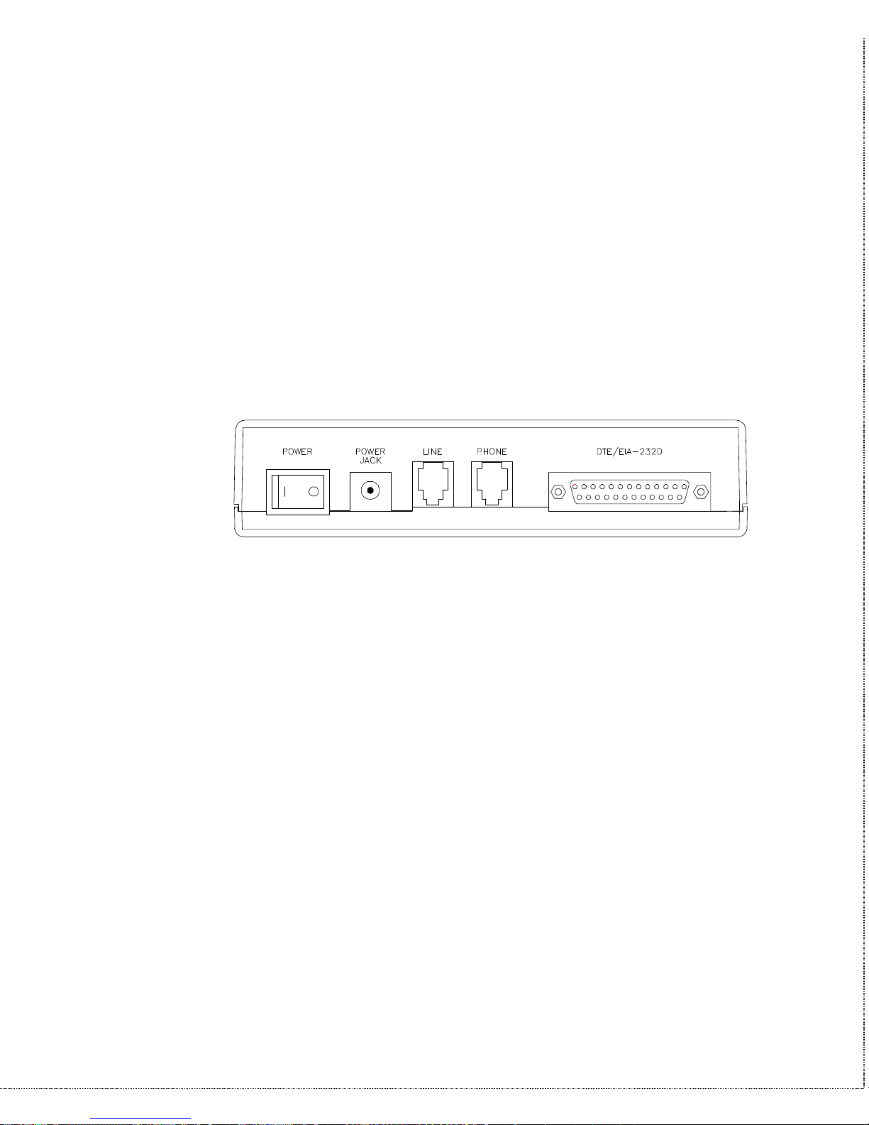
Rear Panel Markings
The U-336E rear panel is shown below:
Figure 2-2 Rear Panel
The following explains the connectors and switch on the rear panel.
• POWER
Power switch, turns the modem ON or OFF.
• POWER JACK
Input terminal for power adapter.
• LINE
Dial-up line RJ-11 terminal jack, for connection to a 2-wire
dial-up or 2-wire leased line.
• PHONE
RJ-11 terminal jack, for connection to a telephone set.

10 Installation
• EIA-232D
Serial port DB25S connector, for connection to the serial port
of a DTE (computer/terminal). Pin assignments are listed in
Chapter 11 Connector Pinouts for your reference. The signalpin assignments for RJ-11 phone jacks are also listed in Chapter
11 Connector Pinouts.
Modem Connection
When you connect your modem to the power line, make sure you
only use the power adapter that is supplied with this unit. Use of
another adapter may not allow your modem to operate and could
result in serious damage to the unit.
This adapter is rated for direct connection to an AC power outlet.
Connect your modem as shown in Figure 2-3 Modem Connections.
To Power Adapter
To Telephone
To Dial-Up or Leased Line To DTE/Computer
Figure 2-3 Modem Connections
There are no DIP switches or configuration settings that you need
to worry about. Your modem comes factory pre-set. User
configurations are also conveniently stored in user selectable nonvolatile memories and can be recalled as often as needed.

Installation 11
Powering Up
Once your modem’s power switch is turned ON, a series of
diagnostic tests will be performed. For a more detailed description
of these diagnostic tests, please refer to Chapter 9 Diagnostics &
Troubleshooting.
After performing the diagnostic tests, your modem is ready for use.

12 Installation

Basic Modem Operation 13
3 Basic Modem Operation
This chapter covers the basic commands and techniques involved in
modem operation. In many cases, this is the only information you
will need in order to get up and running with communication
software, and to start making connections with your modem.
Understanding AT Commands
The U-336E communicates asynchronously with computers using
AT commands. AT commands are used to configure and control
your modem. Commands are usually sent to the modem by way of
communication software, but can also be entered manually by the
user with the computer keyboard.
Command statements must be written in a specific form in order for
your modem to recognize them. A command statement always
begins with the letters AT or at. It is then followed by one or more
commands and the <Enter> key.
AT commands can only be issued when your modem is in
“command mode” or “off-line.”
Once your modem has established a connection with another
modem it is said to be “on-line” or in “data mode.” In this mode,
the characters sent to your modem by your computer are
transmitted to the remote modem rather than being interpreted by
your modem as commands.
Using the Windows 95 Hyper Terminal Program
In order to issue an AT command statement, you first need to run a
communication program such as the Microsoft Windows “Hyper
14 Basic Modem Operation
Terminal” program. This program provides a simple method to
manually enter AT commands so you can do such things as
“customize” the settings of your modem, or store commonly used
phone numbers.
Once your modem is connected to your computer’s serial port and
telephone line, open the Windows 95 “Accessories” program
group, and open the Hyper Terminal Program.
The program will prompt you for a name and Icon to use for your
new connection. Type the name Test Connection and press
<Enter>.
Next, you will be prompted for country information, area code and
phone number, and the device used to make the connection. For
this test purpose, do not enter a phone number; simply choose the
COM port your modem is connected to from the “Connect Using”
list. Click “OK” when finished.
The next window sets the COM port settings. The settings used for
your modem should be as follows.
Bits per second: 57600
Data bits: 8
Parity: None
Stop bits: 1
Flow Control: Hardware
Click “OK” when finished. After you have done this, save your new
connection by selecting “Save” from the “File” menu and click
“OK.” A new connection icon will be added to your Hyper
Terminal folder.
You are now ready to start entering AT commands.
In the terminal window, type:
AT<Enter>

Basic Modem Operation 15
Your modem responds
OK
This confirms that the modem and your computer are
communicating correctly.
To test the telephone line connection issue the manual answer
command.
Type:
ATA<Enter>
Your modem will pick up the phone line, and try to communicate.
Normally, this command is only used to answer an incoming call
made from another modem, thus the high pitched tone you will hear
from the speaker. To abort the operation, press any key, or select
“Disconnect” from the “Call” menu.
Dialing and Answering Techniques
Depending on what communications software you use to make
modem connections, you may not have as much control of how the
modem dials the telephone number. This section shows some useful
examples of the AT commands used for dialing and answering
operations. The command characters specific to each function are
shown in bold type.
Dialing using the ATD Command
Touch Tone Dialing: ATDT 555 1212
Pulse Dialing: ATDP 555 1212
Tone and Pulse Dialing: ATDP 555 1212 WT 24
Dialing Through a PBX: ATDT 9 W 555 1212
OONOTE: THE 'W' IN THE DIAL STRING WILL CAUSE THE MODEM TO WAIT FOR A SECOND
DIAL TONE BEFORE IT CONTINUES TO DIAL.

16 Basic Modem Operation
Pausing During Dialing: ATDT 9,,555 1212
OONOTE: THE PAUSE TIME FOR EACH COMMA IS DEFINED BY S REGISTER S8. DEFAULT IS
2 SECONDS PER COMMA.
Dialing Without Waiting for Dial Tone: ATX0D, 555 1212
Originating a call using an Answer Tone: ATDT 555 1212,,,,,,R
Redialing the Last Number Called: ATDL
Waiting for Five Seconds of Silence: ATDT 800 555 1212 @
123456,1 714 555 1212
Transferring a Call (using flash hook): ATDT! 2468
Auto-Answer and Hook Controls
Enabling Auto-Answer: ATS0=n
OONOTE: IN THIS EXAMPLE, N IS A NUMBER FROM 1 TO 255 THAT CORRESPONDS TO THE
NUMBER OF RINGS AFTER WHICH YOUR MODEM ANSWERS AN INCOMING CALL.
Disabling Auto-Answer: ATS0=0
Manually Answering a Call: ATA
Take modem off-hook: ATH1
Hang up modem (on-hook): ATH0
Manually Disconnecting a Call: +++ATH
Making Your First Connection
In order to check your modem we will use the connection you
created in the Hyper Terminal program to dial the ZyXEL BBS. If
you are using a different terminal program, run the program
according to the instructions provided with it.

Basic Modem Operation 17
Start the terminal program by double-clicking the Test Connection
icon. When the terminal window appears, enter the dial command
with ZyXEL’s BBS as the phone number.
Type:
ATDT17146930762 <enter> (Omit the ‘1714’ if you are in this
area code)
The modem will go off-hook, dial the number, and after a few
seconds of negotiation tones, you should be connected to our BBS.
You will receive a login message asking for your name. For the
purposes of this example you need not continue. Just click the
“disconnect” icon on the toolbar.
Quick Tips when issuing AT Commands
• The ENTER or RETURN key must be pressed to execute a
command.
• Multiple AT commands can be combined into one line. For
example, AT&D2 and AT&N0 can be combined into one line
AT&D2&N0.
• Your modem processes commands from left to right. The AT
command that appears to the right might over-write the
command to the left if they are trying to accomplish tasks or set
modes that cannot coexist.
• If you see duplicated characters for each one you type, your
modem and software both have their “echo” feature turned on.
The modem command echo state is switched off using ATE0
and on using ATE1 (default). To eliminate the double
characters, turn off the software’s command echo rather than
using the ATE0 command. If you see no characters in your
18 Basic Modem Operation
terminal window when you type, the modem’s echo setting is
probably set to off. In this case, issue the ATE1 command.
• When a command is successfully issued and accepted, a modem
responds with a “Result Code.” Your modem supports both
“verbose” result codes (i.e. “OK”), and “numerical” result
codes (i.e. “0”). You can use the ATV command to set it one
way or the other as follows.
Command Description
ATV0 Select numerical result code.
ATV1 Select verbose result code.
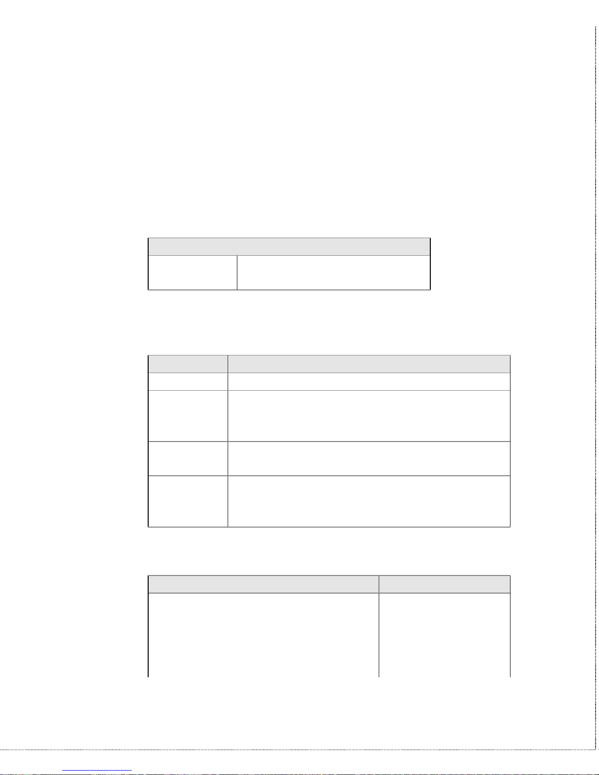
There are a few basic commands that do not require the “AT”
command prefix. These are as follows:
Command Description
A/ Repeats the last issued AT command once.
A> Repeats the last issued AT command once, or
re-dials the last dialed number up to 9 times
until a key is pressed or a connection is made.
<any key> Terminates the current connection attempt, if
pressed while modem is handshaking.
+++ Escape code sequence. Entered while the
modem is in Data Mode. Returns modem to
Command Mode.
The U-336E supports several groups of AT commands:
AT Command Set/Type Example
Basic AT (Hayes compatible) ATB0
Basic AT$ (on line help) AT$
Extended AT& commands AT&N0
Extended AT* commands AT*I1
Fax AT+ commands AT+FCLASS=2
 Loading...