

Page 1

P-320W
802.11g Wireless Firewall Router
User’s Guide
Version 1.00
11/2005
Edition 1
Page 2

Page 3

P-320W User’s Guide
Copyright
Copyright © 2005 by ZyXEL Communications Corporation.
The contents of this publication may not be reproduced in any part or as a whole, transcribed,
stored in a retrieval system, translated into any language, or transmitted in any form or by any
means, electronic, mechanical, magnetic, optical, chemical, photocopying, manual, or
otherwise, without the prior written permission of ZyXEL Communications Corporation.
Published by ZyXEL Communications Corporation. All rights reserved.
Disclaimer
ZyXEL does not assume any liability arising out of the application or use of any products, or
software described herein. Neither does it convey any license under its patent rights nor the
patent rights of others. ZyXEL further reserves the right to make changes in any products
described herein without notice. This publication is subject to change without notice.
Trademarks
ZyNOS (ZyXEL Network Operating System) is a registered trademark of ZyXEL
Communications, Inc. Other trademarks mentioned in this publication are used for
identification purposes only and may be properties of their respective owners.
Copyright 3
Page 4

P-320W User’s Guide
Federal Communications
Commission (FCC) Interference
Statement
This device complies with Part 15 of FCC rules. Operation is subject to the following two
conditions:
• This device may not cause harmful interference.
• This device must accept any interference received, including interference that may cause
undesired operations.
This equipment has been tested and found to comply with the limits for a Class B digital
device pursuant to Part 15 of the FCC Rules. These limits are designed to provide reasonable
protection against harmful interference in a commercial environment. This equipment
generates, uses, and can radiate radio frequency energy, and if not installed and used in
accordance with the instructions, may cause harmful interference to radio communications.
If this equipment does cause harmful interference to radio/television reception, which can be
determined by turning the equipment off and on, the user is encouraged to try to correct the
interference by one or more of the following measures:
• Reorient or relocate the receiving antenna.
• Increase the separation between the equipment and the receiver.
• Connect the equipment into an outlet on a circuit different from that to which the receiver
is connected.
• Consult the dealer or an experienced radio/TV technician for help.
Caution
1 To comply with FCC RF exposure compliance requirements, a separation distance of at
least 20 cm must be maintained between the antenna of this device and all persons.
2 This transmitter must not be co-located or operating in conjunction with any other
antenna or transmitter.
Notice 1
Changes or modifications not expressly approved by the party responsible for compliance
could void the user's authority to operate the equipment.
This Class B digital apparatus complies with Canadian ICES-003.
Cet appareil numérique de la classe B est conforme à la norme NMB-003 du Canada.
4 Federal Communications Commission (FCC) Interference Statement
Page 5

P-320W User’s Guide
Certifications
1 Go to www.zyxel.com
2 Select your product from the drop-down list box on the ZyXEL home page to go to that
product's page.
3 Select the certification you wish to view from this page.
Federal Communications Commission (FCC) Interference Statement 5
Page 6

P-320W User’s Guide
For your safety, be sure to read and follow all warning notices and instructions.
• To reduce the risk of fire, use only No. 26 AWG (American Wire Gauge) or larger
telecommunication line cord.
• Do NOT open the device or unit. Opening or removing covers can expose you to
dangerous high voltage points or other risks. ONLY qualified service personnel can
service the device. Please contact your vendor for further information.
• Use ONLY the dedicated power supply for your device. Connect the power cord or
power adaptor to the right supply voltage (110V AC in North America or 230V AC in
Europe).
• Do NOT use the device if the power supply is damaged as it might cause electrocution.
• If the power supply is damaged, remove it from the power outlet.
• Do NOT attempt to repair the power supply. Contact your local vendor to order a new
power supply.
• Place connecting cables carefully so that no one will step on them or stumble over them.
Do NOT allow anything to rest on the power cord and do NOT locate the product where
anyone can walk on the power cord.
• If you wall mount your device, make sure that no electrical, gas or water pipes will be
damaged.
• Do NOT install nor use your device during a thunderstorm. There may be a remote risk of
electric shock from lightning.
• Do NOT expose your device to dampness, dust or corrosive liquids.
• Do NOT use this product near water, for example, in a wet basement or near a swimming
pool.
• Make sure to connect the cables to the correct ports.
• Do NOT obstruct the device ventilation slots, as insufficient airflow may harm your
device.
• Do NOT store things on the device.
• Connect ONLY suitable accessories to the device.
Safety Warnings
6 Safety Warnings
Page 7

P-320W User’s Guide
ZyXEL Limited Warranty
ZyXEL warrants to the original end user (purchaser) that this product is free from any defects
in materials or workmanship for a period of up to two years from the date of purchase. During
the warranty period, and upon proof of purchase, should the product have indications of failure
due to faulty workmanship and/or materials, ZyXEL will, at its discretion, repair or replace the
defective products or components without charge for either parts or labor, and to whatever
extent it shall deem necessary to restore the product or components to proper operating
condition. Any replacement will consist of a new or re-manufactured functionally equivalent
product of equal value, and will be solely at the discretion of ZyXEL. This warranty shall not
apply if the product is modified, misused, tampered with, damaged by an act of God, or
subjected to abnormal working conditions.
Note
Repair or replacement, as provided under this warranty, is the exclusive remedy of the
purchaser. This warranty is in lieu of all other warranties, express or implied, including any
implied warranty of merchantability or fitness for a particular use or purpose. ZyXEL shall in
no event be held liable for indirect or consequential damages of any kind of character to the
purchaser.
To obtain the services of this warranty, contact ZyXEL's Service Center for your Return
Material Authorization number (RMA). Products must be returned Postage Prepaid. It is
recommended that the unit be insured when shipped. Any returned products without proof of
purchase or those with an out-dated warranty will be repaired or replaced (at the discretion of
ZyXEL) and the customer will be billed for parts and labor. All repaired or replaced products
will be shipped by ZyXEL to the corresponding return address, Postage Paid. This warranty
gives you specific legal rights, and you may also have other rights that vary from country to
country.
ZyXEL Limited Warranty 7
Page 8

P-320W User’s Guide
Please have the following information ready when you contact customer support.
• Product model and serial number.
• Warranty Information.
• Date that you received your device.
• Brief description of the problem and the steps you took to solve it.
Customer Support
METHOD
LOCATION
CORPORATE
HEADQUARTERS
(WORLDWIDE)
CZECH REPUBLIC
DENMARK
FINLAND
FRANCE
GERMANY
HUNGARY
KAZAKHSTAN
NORTH AMERICA
NORWAY
SUPPORT E-MAIL TELEPHONE
SALES E-MAIL FAX FTP SITE
support@zyxel.com.tw +886-3-578-3942 www.zyxel.com
sales@zyxel.com.tw +886-3-578-2439 ftp.zyxel.com
info@cz.zyxel.com +420-241-091-350 www.zyxel.cz ZyXEL Communications
info@cz.zyxel.com +420-241-091-359
support@zyxel.dk +45-39-55-07-00 www.zyxel.dk ZyXEL Communications A/S
sales@zyxel.dk +45-39-55-07-07
support@zyxel.fi +358-9-4780-8411 www.zyxel.fi ZyXEL Communications Oy
sales@zyxel.fi +358-9-4780 8448
info@zyxel.fr +33-4-72-52-97-97 www.zyxel.fr ZyXEL France
+33-4-72-52-19-20
support@zyxel.de +49-2405-6909-0 www.zyxel.de ZyXEL Deutschland GmbH.
sales@zyxel.de +49-2405-6909-99
support@zyxel.hu +36-1-3361649 www.zyxel.hu ZyXEL Hungary
info@zyxel.hu +36-1-3259100
http://zyxel.kz/support +7-3272-590-698 www.zyxel.kz ZyXEL Kazakhstan
sales@zyxel.kz +7-3272-590-689
support@zyxel.com 1-800-255-4101
+1-714-632-0882
sales@zyxel.com +1-714-632-0858 ftp.us.zyxel.com
support@zyxel.no +47-22-80-61-80 www.zyxel.no ZyXEL Communications A/S
sales@zyxel.no +47-22-80-61-81
A
WEB SITE
www.europe.zyxel.com
ftp.europe.zyxel.com
www.us.zyxel.com ZyXEL Communications Inc.
REGULAR MAIL
ZyXEL Communications Corp.
6 Innovation Road II
Science Park
Hsinchu 300
Ta iw a n
Czech s.r.o.
Modranská 621
143 01 Praha 4 - Modrany
Ceská Republika
Columbusvej
2860 Soeborg
Denmark
Malminkaari 10
00700 Helsinki
Finland
1 rue des Vergers
Bat. 1 / C
69760 Limonest
France
Adenauerstr. 20/A2 D-52146
Wuerselen
Germany
48, Zoldlomb Str.
H-1025, Budapest
Hungary
43, Dostyk ave.,Office 414
Dostyk Business Centre
050010, Almaty
Republic of Kazakhstan
1130 N. Miller St.
Anaheim
CA 92806-2001
U.S.A.
Nils Hansens vei 13
0667 Oslo
Norway
8 Customer Support
Page 9

P-320W User’s Guide
METHOD
LOCATION
POLAND
RUSSIA
SPAIN
SWEDEN
UKRAINE
UNITED KINGDOM
A. “+” is the (prefix) number you enter to make an international telephone call.
SUPPORT E-MAIL TELEPHONE
SALES E-MAIL FAX FTP SITE
info@pl.zyxel.com +48-22-5286603 www.pl.zyxel.com ZyXEL Communications
+48-22-5206701
http://zyxel.ru/support +7-095-542-89-29 www.zyxel.ru ZyXEL Russia
sales@zyxel.ru +7-095-542-89-25
support@zyxel.es +34-902-195-420 www.zyxel.es ZyXEL Communications
sales@zyxel.es +34-913-005-345
support@zyxel.se +46-31-744-7700 www.zyxel.se ZyXEL Communications A/S
sales@zyxel.se +46-31-744-7701
support@ua.zyxel.com +380-44-247-69-78 www.ua.zyxel.com ZyXEL Ukraine
sales@ua.zyxel.com +380-44-494-49-32
support@zyxel.co.uk +44-1344 303044
08707 555779 (UK only)
sales@zyxel.co.uk +44-1344 303034 ftp.zyxel.co.uk
A
WEB SITE
REGULAR MAIL
ul.Emilli Plater 53
00-113 Warszawa
Poland
Ostrovityanova 37a Str.
Moscow, 117279
Russia
Alejandro Villegas 33
1º, 28043 Madrid
Spain
Sjöporten 4, 41764 Göteborg
Sweden
13, Pimonenko Str.
Kiev, 04050
Ukraine
www.zyxel.co.uk ZyXEL Communications UK
Ltd.,11 The Courtyard,
Eastern Road, Bracknell,
Berkshire, RG12 2XB,
United Kingdom (UK)
Customer Support 9
Page 10

P-320W User’s Guide
10 Customer Support
Page 11

P-320W User’s Guide
Table of Contents
Copyright ..................................................................................................................3
Federal Communications Commission (FCC) Interference Statement ............... 4
Safety Warnings ....................................................................................................... 6
ZyXEL Limited Warranty.......................................................................................... 7
Customer Support.................................................................................................... 8
Table of Contents ................................................................................................... 11
Preface ....................................................................................................................25
Chapter 1
Getting to Know Your Prestige ............................................................................. 27
1.1 Prestige Overview ..............................................................................................27
1.2 Prestige Features ...............................................................................................27
1.2.1 Physical Features .....................................................................................27
1.2.2 Non-Physical Features .............................................................................28
1.2.3 Wireless Features .....................................................................................30
1.3 Applications for the Prestige ..............................................................................31
1.3.1 Secure Broadband Internet Access via Cable or DSL Modem .................31
1.3.2 Wireless LAN Application .........................................................................32
1.3.3 Front Panel LEDs .....................................................................................32
Chapter 2
Introducing the Web Configurator........................................................................ 35
2.1 Web Configurator Overview ...............................................................................35
2.2 Accessing the Prestige Web Configurator .........................................................35
2.3 Resetting the Prestige ........................................................................................37
2.3.1 Procedure To Use The Reset Button ........................................................37
2.4 Navigating the Prestige Web Configurator .........................................................37
2.4.1 Navigation Panel .......................................................................................39
2.4.2 Summary: DHCP Table..............................................................................41
2.4.3 Summary: Association List ........................................................................42
2.4.4 Summary: Packet Statistics .......................................................................42
Chapter 3
Connection Wizard................................................................................................. 45
3.1 Wizard Setup ......................................................................................................45
Table of Contents 11
Page 12

P-320W User’s Guide
Chapter 4
Wireless LAN .......................................................................................................... 61
3.2 Connection Wizard: STEP 1: System Information .............................................46
3.2.1 System Name ...........................................................................................46
3.2.2 Domain Name ...........................................................................................46
3.3 Connection Wizard: STEP 2: Wireless LAN .......................................................47
3.3.1 Basic(WEP) Security .................................................................................49
3.3.2 Extend(WPA-PSK) Security.......................................................................50
3.3.3 OTIST ........................................................................................................51
3.4 Connection Wizard: STEP 3: Internet Configuration ..........................................52
3.4.1 Ethernet Connection Type ........................................................................53
3.4.2 PPPoE Connection Type ..........................................................................53
3.4.3 PPTP Connection Type ............................................................................55
3.4.4 Your IP Address .........................................................................................56
3.4.5 WAN MAC Address ...................................................................................57
3.4.6 Connection Wizard Complete ....................................................................58
4.1 Introduction ........................................................................................................61
4.2 Wireless Security Overview ...............................................................................61
4.2.1 Encryption .................................................................................................61
4.2.2 Authentication ...........................................................................................61
4.2.3 Restricted Access .....................................................................................62
4.2.4 Hide Prestige Identity ................................................................................62
4.2.5 Using OTIST .............................................................................................62
4.3 Configuring Wireless LAN on the Prestige .........................................................62
4.4 General Wireless LAN Screen ..........................................................................63
4.4.1 No Security ...............................................................................................64
4.4.2 WEP Encryption ........................................................................................65
4.4.3 Introduction to WPA .................................................................................67
4.4.4 WPA-PSK Application Example ................................................................67
4.4.5 WPA-PSK Authentication Screen .............................................................68
4.4.6 WPA with RADIUS Application Example ..................................................69
4.4.7 Wireless Client WPA Supplicants .............................................................69
4.4.8 WPA Authentication Screen ......................................................................69
4.4.9 IEEE 802.1x Overview ..............................................................................70
4.4.10 IEEE 802.1x and Dynamic WEP Key Exchange Screen ........................71
4.5 OTIST .................................................................................................................72
4.5.1 Enabling OTIST ........................................................................................72
4.5.1.1 AP ...................................................................................................72
4.5.1.2 Wireless Client ................................................................................74
4.5.2 Starting OTIST ..........................................................................................75
4.5.3 Notes on OTIST ........................................................................................75
4.6 MAC Filter ..........................................................................................................76
12 Table of Contents
Page 13

P-320W User’s Guide
4.7 Wireless LAN Advanced Screen ........................................................................78
Chapter 5
WAN......................................................................................................................... 81
5.1 WAN IP Address Assignment .............................................................................81
5.2 IP Address and Subnet Mask .............................................................................81
5.3 DNS Server Address Assignment ......................................................................82
5.4 TCP/IP Priority (Metric) ......................................................................................82
5.5 WAN MAC Address ............................................................................................83
5.6 Internet Connection ............................................................................................83
5.6.1 Ethernet Encapsulation .............................................................................83
5.6.2 PPPoE Encapsulation ...............................................................................85
5.6.3 PPTP Encapsulation .................................................................................87
5.7 Advanced WAN Screen ......................................................................................89
5.8 Traffic Redirect ...................................................................................................90
5.9 Traffic Redirect Screen .......................................................................................90
Chapter 6
LAN..........................................................................................................................93
6.1 LAN Overview ....................................................................................................93
6.1.1 IP Pool Setup ............................................................................................93
6.1.2 System DNS Servers ................................................................................93
6.2 LAN TCP/IP ........................................................................................................93
6.2.1 Factory LAN Defaults ................................................................................93
6.2.2 IP Address and Subnet Mask ...................................................................94
6.3 IP Screen ...........................................................................................................94
Chapter 7
DHCP Server........................................................................................................... 95
7.1 DHCP .................................................................................................................95
7.2 DHCP Screen .....................................................................................................95
7.3 Static DHCP Screen ...........................................................................................96
7.4 Client List Screen ...............................................................................................97
Chapter 8
Network Address Translation (NAT).....................................................................99
8.1 NAT Overview ....................................................................................................99
8.1.1 NAT Definitions .........................................................................................99
8.1.2 What NAT Does ......................................................................................100
8.1.3 How NAT Works .....................................................................................100
8.1.4 NAT Application ......................................................................................101
8.1.5 Default Server IP Address ......................................................................101
8.1.6 Port Forwarding: Services and Port Numbers ........................................102
Table of Contents 13
Page 14

P-320W User’s Guide
Chapter 9
Firewall..................................................................................................................109
8.1.7 Configuring Servers Behind SUA (Example) ..........................................103
8.2 General NAT Screen ........................................................................................103
8.3 Port Forwarding Screen ...................................................................................104
8.3.1 Rule Setup Screen...................................................................................105
8.4 Trigger Port Forwarding ...................................................................................106
8.4.1 Trigger Port Forwarding Example ...........................................................106
8.4.2 Two Points To Remember About Trigger Ports .......................................107
8.5 Trigger Port Forwarding Screen .......................................................................107
9.1 Introduction to Firewall .....................................................................................109
9.1.1 What is a Firewall? .................................................................................109
9.1.2 Stateful Inspection Firewall. ....................................................................109
9.1.3 About the Prestige Firewall .....................................................................109
9.1.4 Guidelines For Enhancing Security With Your Firewall ..........................110
9.2 General Firewall Screen ...................................................................................110
9.3 Services Screen .............................................................................................. 111
9.3.1 Services ..................................................................................................113
Chapter 10
Static Route Screens ........................................................................................... 115
10.1 Static Route Overview ....................................................................................115
10.2 IP Static Route Screen ................................................................................... 115
10.2.1 Static Route Setup Screen.....................................................................116
Chapter 11
Remote Management Screens ............................................................................ 119
11.1 Remote Management Overview ..................................................................... 119
11.1.1 Remote Management Limitations .........................................................119
11.1.2 Remote Management and NAT ............................................................119
11.1.3 System Timeout ...................................................................................120
11.2 WWW Screen .................................................................................................120
11.3 SNMP .............................................................................................................121
11.3.1 Supported MIBs ....................................................................................122
11.3.2 SNMP Traps ..........................................................................................122
11.4 SNMP Screen .................................................................................................122
11.5 Security Screen ..............................................................................................123
Chapter 12
UPnP...................................................................................................................... 125
12.1 Universal Plug and Play Overview ................................................................125
12.1.1 How Do I Know If I'm Using UPnP? ......................................................125
14 Table of Contents
Page 15

P-320W User’s Guide
12.1.2 NAT Traversal .......................................................................................125
12.1.3 Cautions with UPnP ..............................................................................125
12.2 UPnP and ZyXEL ...........................................................................................126
12.3 UPnP Screen .................................................................................................126
12.4 Installing UPnP in Windows Example ............................................................127
12.4.1 Installing UPnP in Windows Me ............................................................127
12.4.2 Installing UPnP in Windows XP ............................................................128
12.5 Using UPnP in Windows XP Example ..........................................................129
12.5.1 Auto-discover Your UPnP-enabled Network Device .............................130
12.5.2 Web Configurator Easy Access ............................................................133
Chapter 13
System .................................................................................................................. 135
13.1 System Overview ...........................................................................................135
13.2 General Screen ..............................................................................................135
13.3 Dynamic DNS .................................................................................................136
13.3.1 DynDNS Wildcard .................................................................................136
13.4 Dynamic DNS Screen ....................................................................................137
13.5 Time Setting Screen .......................................................................................137
Chapter 14
Logs....................................................................................................................... 141
14.1 View Log .......................................................................................................141
14.2 Log Settings ...................................................................................................142
Chapter 15
Tools ...................................................................................................................... 145
15.1 Firmware Upload Screen ...............................................................................145
15.2 Configuration Screen .....................................................................................146
15.2.1 Backup Configuration ...........................................................................147
15.2.2 Restore Configuration ...........................................................................147
15.2.3 Back to Factory Defaults .......................................................................148
15.3 Restart Screen ...............................................................................................148
Chapter 16
Troubleshooting ...................................................................................................151
16.1 Problems Starting Up the Prestige .................................................................151
16.2 Problems with the LAN ...................................................................................151
16.3 Problems with the WAN .................................................................................152
16.4 Problems with the Password ..........................................................................152
16.5 Problems with Remote Management .............................................................153
16.6 Problems Accessing the Prestige ..................................................................153
16.6.1 Pop-up Windows, JavaScripts and Java Permissions ..........................154
Table of Contents 15
Page 16

P-320W User’s Guide
Appendix A
Product Specifications ........................................................................................ 163
Appendix B
IP Subnetting ........................................................................................................ 165
Appendix C
Setting up Your Computer’s IP Address............................................................ 173
Appendix D
PPPoE ................................................................................................................... 189
Appendix E
PPTP......................................................................................................................191
16.6.1.1 Internet Explorer Pop-up Blockers ..............................................154
16.6.1.2 JavaScripts ..................................................................................157
16.6.1.3 Java Permissions ........................................................................159
16.6.2 ActiveX Controls in Internet Explorer ....................................................161
Appendix F
Wireless LANs ...................................................................................................... 195
Appendix G
Antenna Selection and Positioning Recommendation..................................... 209
16 Table of Contents
Page 17

P-320W User’s Guide
List of Figures
Figure 1 Secure Internet Access via Cable, DSL or Wireless Modem ................................ 31
Figure 2 Internet Access Application Example .................................................................... 32
Figure 3 Front Panel ...........................................................................................................32
Figure 4 Login ..................................................................................................................... 36
Figure 5 Language Selection .............................................................................................. 36
Figure 6 Change Password Screen .................................................................................... 36
Figure 7 Select the Mode .................................................................................................... 37
Figure 8 Web Configurator Status Screen .......................................................................... 38
Figure 9 Summary: DHCP Table ......................................................................................... 41
Figure 10 Summary: Association List .................................................................................. 42
Figure 11 Summary: Packet Statistics ................................................................................. 43
Figure 12 Select a Mode ..................................................................................................... 45
Figure 13 Welcome to the Connection Wizard .................................................................... 46
Figure 14 Connection Wizard: STEP 1: System Information .............................................. 47
Figure 15 Connection Wizard: STEP 2: Wireless LAN ....................................................... 48
Figure 16 Basic(WEP) Security ........................................................................................... 49
Figure 17 Extend(WPA-PSK) Security ................................................................................ 50
Figure 18 OTIST ................................................................................................................. 51
Figure 19 Connection Wizard: STEP 3: WAN Connection Type. ........................................ 52
Figure 20 Ethernet Connection Type .................................................................................. 53
Figure 21 PPPoE Connection Type .................................................................................... 54
Figure 22 PPTP Connection Type ....................................................................................... 55
Figure 23 Your IP Address .................................................................................................. 56
Figure 24 WAN MAC Address ............................................................................................. 58
Figure 25 Connection Wizard Complete ............................................................................. 59
Figure 26 Connection Wizard: Congratulation .................................................................... 59
Figure 27 Wireless: General .............................................................................................. 63
Figure 28 Wireless: No Security .......................................................................................... 65
Figure 29 Wireless: Static WEP Encryption ........................................................................ 66
Figure 30 WPA-PSK Authentication .................................................................................... 68
Figure 31 Wireless: WPA-PSK ............................................................................................ 68
Figure 32 WPA with RADIUS Application Example ............................................................ 69
Figure 33 Wireless: WPA .................................................................................................... 70
Figure 34 Wireless: 802.1x and Dynamic WEP .................................................................. 71
Figure 35 Wireless: OTIST .................................................................................................. 73
Figure 36 Example Wireless Client OTIST Screen ............................................................. 74
17
Page 18

P-320W User’s Guide
Figure 37 Security Key ........................................................................................................ 75
Figure 38 OTIST in Progress (AP) ...................................................................................... 75
Figure 39 OTIST in Progress (Client) .................................................................................. 75
Figure 40 No AP with OTIST Found ........................................................................... 75
Figure 41 Start OTIST? ....................................................................................................... 76
Figure 42 Wireless: MAC Address Filter ............................................................................. 77
Figure 43 Wireless: Advanced ............................................................................................ 78
Figure 44 WAN: Ethernet Encapsulation ............................................................................. 84
Figure 45 WAN: PPPoE Encapsulation ............................................................................... 86
Figure 46 PPTP Encapsulation ........................................................................................... 88
Figure 47 Advanced ............................................................................................................ 90
Figure 48 Traffic Redirect WAN Setup ................................................................................ 90
Figure 49 WAN: Traffic Redirect .......................................................................................... 91
Figure 50 LAN IP ................................................................................................................. 94
Figure 51 General ............................................................................................................... 95
Figure 52 Static DHCP ........................................................................................................ 97
Figure 53 Client List ............................................................................................................ 98
Figure 54 How NAT Works .................................................................................................. 101
Figure 55 NAT Application With IP Alias ............................................................................. 101
Figure 56 Multiple Servers Behind NAT Example ............................................................... 103
Figure 57 NAT: General ....................................................................................................... 103
Figure 58 Port Forwarding .................................................................................................. 104
Figure 59 NAT: Port Forwarding: Rule Setup ...................................................................... 105
Figure 60 Trigger Port Forwarding Process: Example ........................................................ 107
Figure 61 NAT: Trigger Port ................................................................................................. 108
Figure 62 Firewall: General ................................................................................................. 110
Figure 63 Firewall: Services ................................................................................................ 111
Figure 64 Example of Static Routing Topology ................................................................... 115
Figure 65 IP Static Route .................................................................................................... 116
Figure 66 Static Route Setup .............................................................................................. 117
Figure 67 WWW Remote Management .............................................................................. 120
Figure 68 SNMP Management Model ................................................................................. 121
Figure 69 SNMP Remote Management .............................................................................. 123
Figure 70 Security Remote Management ........................................................................... 124
Figure 71 Configuring UPnP ............................................................................................... 126
Figure 72 Add/Remove Programs: Windows Setup: Communication ................................. 127
Figure 73 Add/Remove Programs: Windows Setup: Communication: Components .......... 128
Figure 74 Network Connections .......................................................................................... 128
Figure 75 Windows Optional Networking Components Wizard .......................................... 129
Figure 76 Networking Services ........................................................................................... 129
Figure 77 Network Connections .......................................................................................... 130
Figure 78 Internet Connection Properties .......................................................................... 131
Figure 79 Internet Connection Properties: Advanced Settings ........................................... 131
18
Page 19

P-320W User’s Guide
Figure 80 Internet Connection Properties: Advanced Settings: Add ................................... 132
Figure 81 System Tray Icon ................................................................................................ 132
Figure 82 Internet Connection Status .................................................................................. 132
Figure 83 Network Connections .......................................................................................... 133
Figure 84 Network Connections: My Network Places ......................................................... 134
Figure 85 Network Connections: My Network Places: Properties: Example ....................... 134
Figure 86 System General ................................................................................................. 135
Figure 87 Dynamic DNS ..................................................................................................... 137
Figure 88 Time Setting ........................................................................................................ 138
Figure 89 View Log .............................................................................................................141
Figure 90 Log Settings ........................................................................................................ 143
Figure 91 Maintenance Firmware Upload ........................................................................... 145
Figure 92 Upload Warning .................................................................................................. 146
Figure 93 Network Temporarily Disconnected .................................................................... 146
Figure 94 Upload Error Message ........................................................................................ 146
Figure 95 Configuration ....................................................................................................... 147
Figure 96 Configuration Restore Successful ....................................................................... 148
Figure 97 Temporarily Disconnected ................................................................................... 148
Figure 98 Configuration Restore Error ................................................................................ 148
Figure 99 System Restart ................................................................................................... 149
Figure 100 Pop-up Blocker ................................................................................................. 154
Figure 101 Internet Options ............................................................................................... 155
Figure 102 Internet Options ................................................................................................ 156
Figure 103 Pop-up Blocker Settings ................................................................................... 157
Figure 104 Internet Options ................................................................................................ 158
Figure 105 Security Settings - Java Scripting ..................................................................... 159
Figure 106 Security Settings - Java .................................................................................... 160
Figure 107 Java (Sun) ......................................................................................................... 160
Figure 108 Internet Options Security .................................................................................. 161
Figure 109 Security Setting ActiveX Controls ..................................................................... 162
Figure 110 WIndows 95/98/Me: Network: Configuration ..................................................... 174
Figure 111 Windows 95/98/Me: TCP/IP Properties: IP Address ......................................... 175
Figure 112 Windows 95/98/Me: TCP/IP Properties: DNS Configuration ............................. 176
Figure 113 Windows XP: Start Menu .................................................................................. 177
Figure 114 Windows XP: Control Panel .............................................................................. 177
Figure 115 Windows XP: Control Panel: Network Connections: Properties ....................... 178
Figure 116 Windows XP: Local Area Connection Properties .............................................. 178
Figure 117 Windows XP: Internet Protocol (TCP/IP) Properties ......................................... 179
Figure 118 Windows XP: Advanced TCP/IP Properties ...................................................... 180
Figure 119 Windows XP: Internet Protocol (TCP/IP) Properties ......................................... 181
Figure 120 Macintosh OS 8/9: Apple Menu ........................................................................ 182
Figure 121 Macintosh OS 8/9: TCP/IP ................................................................................ 182
Figure 122 Macintosh OS X: Apple Menu ........................................................................... 183
19
Page 20

P-320W User’s Guide
Figure 123 Macintosh OS X: Network ................................................................................. 184
Figure 124 Red Hat 9.0: KDE: Network Configuration: Devices ........................................ 185
Figure 125 Red Hat 9.0: KDE: Ethernet Device: General ................................................. 185
Figure 126 Red Hat 9.0: KDE: Network Configuration: DNS ............................................. 186
Figure 127 Red Hat 9.0: KDE: Network Configuration: Activate ....................................... 186
Figure 128 Red Hat 9.0: Dynamic IP Address Setting in ifconfig-eth0 .............................. 187
Figure 129 Red Hat 9.0: Static IP Address Setting in ifconfig-eth0 .................................. 187
Figure 130 Red Hat 9.0: DNS Settings in resolv.conf ...................................................... 187
Figure 131 Red Hat 9.0: Restart Ethernet Card ................................................................ 188
Figure 132 Red Hat 9.0: Checking TCP/IP Properties ...................................................... 188
Figure 133 Single-Computer per Router Hardware Configuration ...................................... 190
Figure 134 ZyWALL as a PPPoE Client .............................................................................. 190
Figure 135 Transport PPP frames over Ethernet ............................................................... 191
Figure 136 PPTP Protocol Overview .................................................................................. 192
Figure 137 Example Message Exchange between Computer and an ANT ........................ 193
Figure 138 Peer-to-Peer Communication in an Ad-hoc Network ........................................ 195
Figure 139 Basic Service Set .............................................................................................. 196
Figure 140 Infrastructure WLAN ......................................................................................... 197
Figure 141 RTS/CTS ........................................................................................................... 198
Figure 142 EAP Authentication ........................................................................................... 201
Figure 143 WEP Authentication Steps ................................................................................ 204
Figure 144 Roaming Example ............................................................................................. 207
20
Page 21

P-320W User’s Guide
List of Tables
Table 1 Front Panel LEDs .................................................................................................. 32
Table 2 Status Screen Icon Key ......................................................................................... 38
Table 3 Web Configurator Status Screen ........................................................................... 38
Table 4 Screens Summary ................................................................................................. 39
Table 5 Summary: DHCP Table ......................................................................................... 41
Table 6 Summary: Wireless Association List ..................................................................... 42
Table 7 Summary: Packet Statistics ................................................................................... 43
Table 8 Connection Wizard: STEP 1: System Information ................................................. 47
Table 9 Connection Wizard: STEP 2: Wireless LAN ......................................................... 48
Table 10 Basic(WEP) Security ........................................................................................... 49
Table 11 Extend(WPA-PSK) Security ................................................................................. 51
Table 12 OTIST .................................................................................................................. 52
Table 13 Connection Wizard: STEP 3: WAN Connection Type .......................................... 53
Table 14 PPPoE Connection Type ..................................................................................... 54
Table 15 PPTP Connection Type ....................................................................................... 55
Table 16 Your IP Address ................................................................................................... 57
Table 17 Example of Network Properties for LAN Servers with Fixed IP Addresses ......... 57
Table 18 WAN MAC Address ............................................................................................. 58
Table 19 ZyAIR Wireless Security Levels .......................................................................... 63
Table 20 Wireless: General ................................................................................................ 64
Table 21 Wireless No Security ........................................................................................... 65
Table 22 Wireless: Static WEP Encryption ......................................................................... 66
Table 23 Wireless: WPA-PSK ............................................................................................ 68
Table 24 Wireless: WPA ..................................................................................................... 70
Table 25 Wireless: 802.1x and Dynamic WEP ................................................................... 71
Table 26 Wireless: OTIST .................................................................................................. 73
Table 27 MAC Address Filter ............................................................................................. 77
Table 28 Wireless: Advanced ............................................................................................. 78
Table 29 Private IP Address Ranges ................................................................................. 81
Table 30 Example of Network Properties for LAN Servers with Fixed IP Addresses ......... 83
Table 31 WAN: Ethernet Encapsulation ............................................................................. 84
Table 32 WAN: PPPoE Encapsulation ............................................................................... 86
Table 33 PPTP Encapsulation ............................................................................................ 88
Table 34 Advanced .............................................................................................................90
Table 35 Traffic Redirect .................................................................................................... 91
Table 36 LAN IP ................................................................................................................. 94
21
Page 22

P-320W User’s Guide
Table 37 General ................................................................................................................ 96
Table 38 Static DHCP ......................................................................................................... 97
Table 39 Client List ............................................................................................................. 98
Table 40 NAT Definitions .................................................................................................... 100
Table 41 Services and Port Numbers ................................................................................. 102
Table 42 NAT: General ....................................................................................................... 103
Table 43 NAT: Port Forwarding .......................................................................................... 105
Table 44 NAT: Port Forwarding: Rule Setup ....................................................................... 106
Table 45 NAT: Trigger Port ................................................................................................. 108
Table 46 Firewall: General ................................................................................................. 111
Table 47 Firewall: Services ................................................................................................ 112
Table 48 Commonly Used Services ................................................................................... 113
Table 49 IP Static Route ..................................................................................................... 116
Table 50 Static Route Setup ............................................................................................... 117
Table 51 WWW Remote Management ............................................................................... 120
Table 52 SNMP Traps ........................................................................................................ 122
Table 53 SNMP Remote Management ............................................................................... 123
Table 54 Security Remote Management ............................................................................ 124
Table 55 Configuring UPnP ................................................................................................ 126
Table 56 System General ................................................................................................... 136
Table 57 Dynamic DNS ...................................................................................................... 137
Table 58 Time Setting ........................................................................................................ 138
Table 59 View Log .............................................................................................................. 142
Table 60 Log Settings .........................................................................................................143
Table 61 Maintenance Firmware Upload ............................................................................ 145
Table 62 Maintenance: Restore Configuration ................................................................... 147
Table 63 Troubleshooting Starting Up Your Prestige .......................................................... 151
Table 64 Troubleshooting the LAN ..................................................................................... 151
Table 65 Troubleshooting the WAN .................................................................................... 152
Table 66 Troubleshooting the Password ............................................................................ 152
Table 67 Troubleshooting Telnet ........................................................................................ 153
Table 68 Troubleshooting Accessing the Prestige ............................................................. 153
Table 69 Device .................................................................................................................. 163
Table 70 Firmware .............................................................................................................. 163
Table 71 Classes of IP Addresses ..................................................................................... 165
Table 72 Allowed IP Address Range By Class ................................................................... 166
Table 73 “Natural” Masks .................................................................................................. 166
Table 74 Alternative Subnet Mask Notation ....................................................................... 167
Table 75 Two Subnets Example ......................................................................................... 167
Table 76 Subnet 1 .............................................................................................................. 168
Table 77 Subnet 2 .............................................................................................................. 168
Table 78 Subnet 1 .............................................................................................................. 169
Table 79 Subnet 2 .............................................................................................................. 169
22
Page 23

P-320W User’s Guide
Table 80 Subnet 3 .............................................................................................................. 169
Table 81 Subnet 4 .............................................................................................................. 170
Table 82 Eight Subnets ...................................................................................................... 170
Table 83 Class C Subnet Planning ..................................................................................... 170
Table 84 Class B Subnet Planning ..................................................................................... 171
Table 85 IEEE802.11g ........................................................................................................ 199
Table 86 Comparison of EAP Authentication Types ........................................................... 205
Table 87 Wireless Security Relational Matrix ..................................................................... 206
23
Page 24

P-320W User’s Guide
24
Page 25

P-320W User’s Guide
Preface
Congratulations on your purchase of the P-320W, 802.11g Wireless Firewall Router. This
manual is designed to guide you through the configuration of your Prestige for its various
applications.
This manual may refer to the P-320W, 802.11g Wireless Firewall Router as the Prestige.
Note: Register your product online to receive e-mail notices of firmware upgrades and
information at
American products.
About This User's Guide
This User’s Guide is designed to guide you through the configuration of your Prestige using
the web configurator.
Related Documentation
www.zyxel.com for global products, or at www.us.zyxel.com for North
• Supporting Disk
Refer to the included CD for support documents.
• Quick Start Guide
The Quick Start Guide is designed to help you get up and running right away. They
contain connection information and instructions on getting started.
• Web Configurator Online Help
Embedded web help for descriptions of individual screens and supplementary
information.
• ZyXEL Glossary and Web Site
Please refer to www.zyxel.com for an online glossary of networking terms and additional
support documentation.
User Guide Feedback
Help us help you! E-mail all User Guide-related comments, questions or suggestions for
improvement to techwriters@zyxel.com.tw or send regular mail to The Technical Writing
Team, ZyXEL Communications Corp., 6 Innovation Road II, Science-Based Industrial Park,
Hsinchu, 300, Taiwan. Thank you!
Syntax Conventions
• “Enter” means for you to type one or more characters. “Select” or “Choose” means for
you to use one predefined choices.
• Mouse action sequences are denoted using a comma. For example, “In Windows, click
Start, Settings and then Control Panel” means first click the Start button, then point
your mouse pointer to Settings and then click Control Panel.
Preface 25
Page 26
P-320W User’s Guide
• “e.g.,” is a shorthand for “for instance”, and “i.e.,” means “that is” or “in other words”.
Graphics Icons Key
Prestige Computer Notebook computer
Server DSLAM Firewall
Modem Switch Router
26 Preface
Page 27

Getting to Know Your Prestige
This chapter introduces the main features and applications of the Prestige.
1.1 Prestige Overview
The Prestige is the ideal secure wireless firewall router for all data passing between the
Internet and LAN’s.
The Prestige provides NAT, port forwarding, firewall, DHCP server and many other powerful
features. The Prestige has an embedded mini-PCI module for 802.11g Wireless LAN
connectivity.
P-320W User’s Guide
CHAPTER 1
The embedded web configurator is easy to operate.
Note: Only use firmware for your Prestige’s specific model.
1.2 Prestige Features
The following sections describe Prestige features.
1.2.1 Physical Features
10/100 Mbps Auto-negotiating Ethernet/Fast Ethernet Interface(s)
This auto-negotiation feature allows the Prestige to detect the speed of incoming transmissions
and adjust appropriately without manual intervention. It allows data transfer of either 10 Mbps
or 100 Mbps in either half-duplex or full-duplex mode depending on your Ethernet network.
Auto-negotiation allows data transfer of 100 Mbps in full-duplex mode
Auto-crossover 10/100 Mbps Ethernet Interface(s)
These interfaces automatically adjust to either a crossover or straight-through Ethernet cable.
4-Port Switch
A combination of switch and router makes your Prestige a cost-effective and viable network
solution. You can add up to four computers to the Prestige without the cost of a hub. Add more
than four computers to your LAN by using a hub.
Chapter 1 Getting to Know Your Prestige 27
Page 28

P-320W User’s Guide
Reset Button
The Prestige reset button is built into the rear panel. Use this button to restore the factory
default password to 1234; IP address to 192.168.1.1, subnet mask to 255.255.255.0 and DHCP
server enabled with a pool of 32 IP addresses starting at 192.168.1.33.
1.2.2 Non-Physical Features
Firewall
The Prestige is a stateful inspection firewall with DoS (Denial of Service) protection. By
default, when the firewall is activated, all incoming traffic from the WAN to the LAN is
blocked unless it is initiated from the LAN. The Prestige firewall supports TCP/UDP
inspection, DoS detection and prevention, real time alerts, reports and logs.
Packet Filtering
The packet filtering mechanism blocks unwanted traffic from entering/leaving your network.
Time and Date
The Prestige allows you to get the current time and date from an external server when you turn
on your Prestige. You can also set the time manually.
Universal Plug and Play (UPnP)
Using the standard TCP/IP protocol, the Prestige and other UPnP enabled devices can
dynamically join a network, obtain an IP address and convey its capabilities to other devices
on the network.
PPPoE
PPPoE facilitates the interaction of a host with an Internet modem to achieve access to highspeed data networks via a familiar "dial-up networking" user interface.
PPTP Encapsulation
Point-to-Point Tunneling Protocol (PPTP) is a network protocol that enables secure transfer of
data from a remote client to a private server, creating a Virtual Private Network (VPN) using a
TCP/IP-based network.
PPTP supports on-demand, multi-protocol and virtual private networking over public
networks, such as the Internet. The Prestige supports one PPTP server connection at any given
time.
28 Chapter 1 Getting to Know Your Prestige
Page 29

P-320W User’s Guide
Dynamic DNS Support
With Dynamic DNS (Domain Name System) support, you can have a static hostname alias for
a dynamic IP address, allowing the host to be more easily accessible from various locations on
the Internet. You must register for this service with a Dynamic DNS service provider.
IP Multicast
Deliver IP packets to a specific group of hosts using IP multicast. IGMP (Internet Group
Management Protocol) is the protocol used to support multicast groups. The latest version is
version 2 (see RFC 2236); the Prestige supports both versions 1 and 2.
SNMP
SNMP (Simple Network Management Protocol) is a protocol used for exchanging
management information between network devices. SNMP is a member of the TCP/IP
protocol suite. Your Prestige supports SNMP agent functionality, which allows a manager
station to manage and monitor the Prestige through the network. The Prestige supports SNMP
version one (SNMPv1) and version two (SNMPv2).
Network Address Translation (NAT)
Network Address Translation (NAT) allows the translation of an Internet protocol address
used within one network (for example a private IP address used in a local network) to a
different IP address known within another network (for example a public IP address used on
the Internet).
Traffic Redirect
Traffic Redirect forwards WAN traffic to a backup gateway on the LAN when the Prestige
cannot connect to the Internet, thus acting as an auxiliary backup when your regular WAN
connection fails.
Port Forwarding
Use this feature to forward incoming service requests to a server on your local network. You
may enter a single port number or a range of port numbers to be forwarded, and the local IP
address of the desired server.
DHCP (Dynamic Host Configuration Protocol)
DHCP (Dynamic Host Configuration Protocol) allows the individual client computers to
obtain the TCP/IP configuration at start-up from a centralized DHCP server. The Prestige has
built-in DHCP server capability, enabled by default, which means it can assign IP addresses,
an IP default gateway and DNS servers to all systems that support the DHCP client.
Chapter 1 Getting to Know Your Prestige 29
Page 30

P-320W User’s Guide
Full Network Management
The embedded web configurator is an all-platform web-based utility that allows you to easily
access the Prestige’s management settings and configure the firewall. Most functions of the
Prestige are also software configurable via the SMT (System Management Terminal)
interface. The SMT is a menu-driven interface that you can access over a telnet connection.
RoadRunner Support
In addition to standard cable modem services, the Prestige supports Time Warner’s
RoadRunner Service.
Logging and Tracing
• Built-in message logging and packet tracing.
• Firewall logs.
• Content filtering logs.
Upgrade Prestige Firmware via LAN
The firmware of the Prestige can be upgraded via the LAN (refer to Maintenance- F/W Upload
Screen).
Embedded FTP and TFTP Servers
The Prestige’s embedded FTP and TFTP Servers enable fast firmware upgrades as well as
configuration file backups and restoration.
1.2.3 Wireless Features
Wireless LAN
The Prestige supports the IEEE 802.11g standard, which is fully compatible with the IEEE
802.11b standard, meaning that you can have both IEEE 802.11b and IEEE 802.11g wireless
clients in the same wireless network.
Note: The Prestige may be prone to RF (Radio Frequency) interference from other
2.4 GHz devices such as microwave ovens, wireless phones, Bluetooth
enabled devices, and other wireless LANs.
Wi-Fi Protected Access
Wi-Fi Protected Access (WPA) is a subset of the IEEE 802.11i security specification standard.
Key differences between WPA and WEP are user authentication and improved data
encryption.
30 Chapter 1 Getting to Know Your Prestige
Page 31

P-320W User’s Guide
Antenna
The Prestige is equipped with a 2dBi fixed antenna to provide clear radio signal between the
wireless stations and the access points.
Wireless LAN MAC Address Filtering
Your Prestige can check the MAC addresses of wireless stations against a list of allowed or
denied MAC addresses.
WEP Encryption
WEP (Wired Equivalent Privacy) encrypts data frames before transmitting over the wireless
network to help keep network communications private.
OTIST (One Touch Intelligent Security Technology)
OTIST allows your Prestige to assign its ESSID and security settings (WEP or WPA-PSK) to
the ZyXEL wireless adapters that support OTIST and are within transmission range. The
ZyXEL wireless adapters must also have OTIST enabled.
Association List
With the association list, you can see the list of the wireless stations that are currently using the
Prestige to access your wired network.
1.3 Applications for the Prestige
Here are some examples of what you can do with your Prestige.
1.3.1 Secure Broadband Internet Access via Cable or DSL Modem
You can connect a cable modem, DSL or wireless modem to the Prestige for broadband
Internet access via an Ethernet or a wireless port on the modem. The Prestige guarantees not
only high speed Internet access, but secure internal network protection and traffic management
as well.
Figure 1 Secure Internet Access via Cable, DSL or Wireless Modem
Chapter 1 Getting to Know Your Prestige 31
Page 32
P-320W User’s Guide
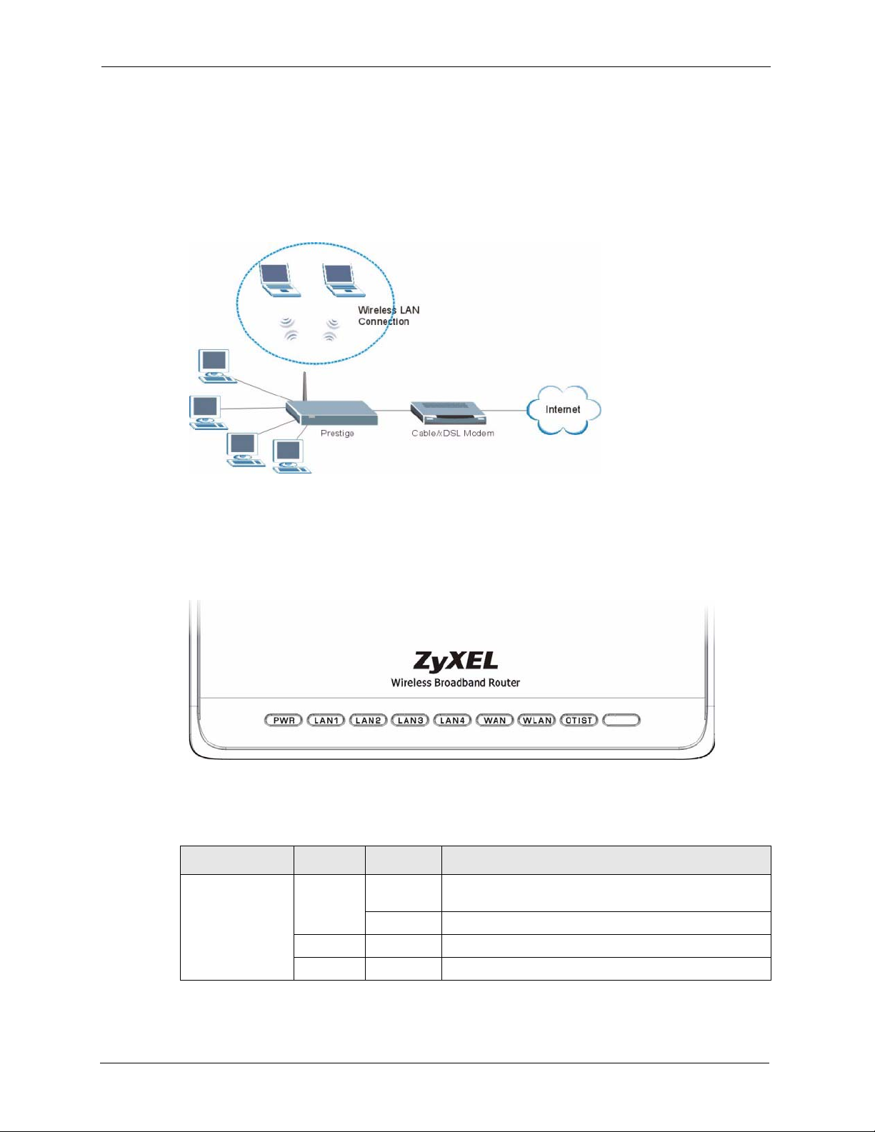
1.3.2 Wireless LAN Application
Add a wireless LAN to your existing network without expensive network cables. Wireless
stations can move freely anywhere in the coverage area and use resources on the wired
network.
Figure 2 Internet Access Application Example
1.3.3 Front Panel LEDs
Figure 3 Front Panel
The following table describes the LEDs.
Table 1 Front Panel LEDs
LED COLOR STATUS DESCRIPTION
PWR Green On The Prestige is receiving power and functioning
Red On Power to the Prestige is too low.
None Off The Prestige is not receiving power.
properly.
Blinking The Prestige is performing testing.
32 Chapter 1 Getting to Know Your Prestige
Page 33

P-320W User’s Guide
Table 1 Front Panel LEDs (continued)
LED COLOR STATUS DESCRIPTION
LAN 1-4 Green On The Prestige has a successful 10Mb Ethernet
connection.
Blinking The Prestige is sending/receiving data.
Amber On The Prestige has a successful 100Mb Ethernet
connection.
Blinking The Prestige is sending/receiving data.
None Off The LAN is not connected.
WAN Green On The Prestige has a successful 10Mb WAN connection.
Blinking The Prestige is sending/receiving data.
Amber On The Prestige has a successful 100Mb Ethernet
connection.
Blinking The Prestige is sending/receiving data.
None Off The WAN connection is not ready, or has failed.
WLAN Green On The Prestige is ready, but is not sending/receiving data
through the wireless LAN.
Blinking The Prestige is sending/receiving data through the
wireless LAN.
None Off The wireless LAN is not ready or has failed.
OTIST Green Blinking OTIST is in progress
On OTIST is activated and the wireless security settings are
given to a wireless client. The LED remains on unless
the WLAN settings are changed.
None Off OTIST is not activated or WLAN settings are manually
configured after OTIST is successful.
Chapter 1 Getting to Know Your Prestige 33
Page 34

P-320W User’s Guide
34 Chapter 1 Getting to Know Your Prestige
Page 35

Introducing the Web
This chapter describes how to access the Prestige web configurator and provides an overview
of its screens.
2.1 Web Configurator Overview
The web configurator is an HTML-based management interface that allows easy Prestige
setup and management via Internet browser. Use Internet Explorer 6.0 and later or Netscape
Navigator 7.0 and later versions. The recommended screen resolution is 1024 by 768 pixels.
P-320W User’s Guide
CHAPTER 2
Configurator
In order to use the web configurator you need to allow:
• Web browser pop-up windows from your device. Web pop-up blocking is enabled by
default in Windows XP SP (Service Pack) 2.
• JavaScripts (enabled by default).
• Java permissions (enabled by default).
See the Troubleshooting chapter to see how to make sure these functions are allowed in
Internet Explorer.
2.2 Accessing the Prestige Web Configurator
1 Make sure your Prestige hardware is properly connected and prepare your computer/
computer network to connect to the Prestige (refer to the Quick Start Guide).
2 Launch your web browser.
3 Type "192.168.1.1" as the URL.
4 Type "1234" (default) as the password and click Login. In some versions, the default
password appears automatically - if this is the case, click Login.
Chapter 2 Introducing the Web Configurator 35
Page 36
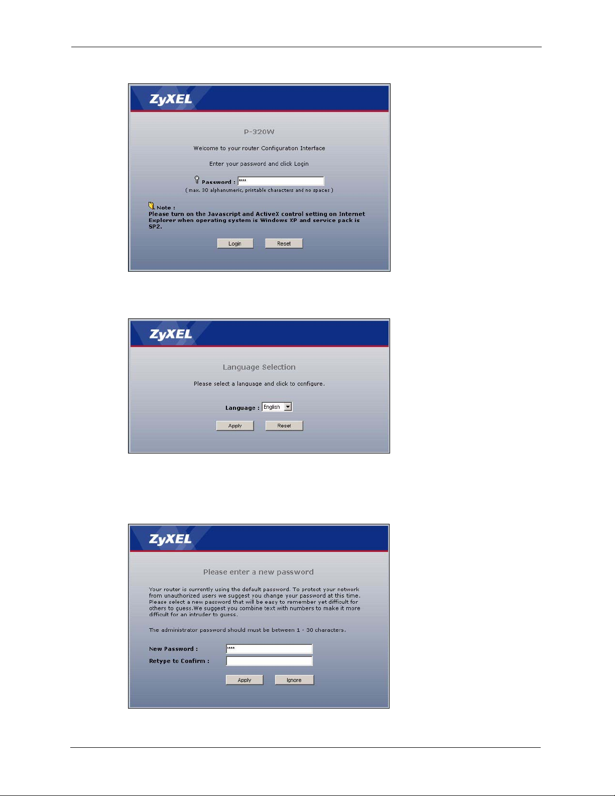
P-320W User’s Guide
Figure 4 Login
5 Select your language. click Apply.
Figure 5 Language Selection
6 You should see a screen asking you to change your password (highly recommended) as
shown next. Type a new password (and retype it to confirm) and click Apply or click
Ignore.
Figure 6 Change Password Screen
36 Chapter 2 Introducing the Web Configurator
Page 37

P-320W User’s Guide
7 Click Go to Wizard setup to do initial configuration withs the wizard, click Go to
Advanced setup to configure advanced features, or click Exit to log out of the web
configurator.
Figure 7 Select the Mode
Note: The management session automatically times out when the time period set in
the Administrator Inactivity Timer field expires (default five minutes). Simply
log back into the Prestige if this happens to you.
2.3 Resetting the Prestige
If you forget your password or cannot access the web configurator, you will need to use the
RESET button at the back of the Prestige to reload the factory-default configuration file. This
means that you will lose all configurations that you had previously and the password will be
reset to “1234”.
2.3.1 Procedure To Use The Reset Button
1 Make sure the PWR LED is on (not blinking).
2 Press the RESET button for ten seconds or until the PWR LED begins to blink and then
release it. When the PWR LED begins to blink, the defaults have been restored and the
Prestige restarts.
2.4 Navigating the Prestige Web Configurator
The following summarizes how to navigate the web configurator from the Status screen.
Chapter 2 Introducing the Web Configurator 37
Page 38
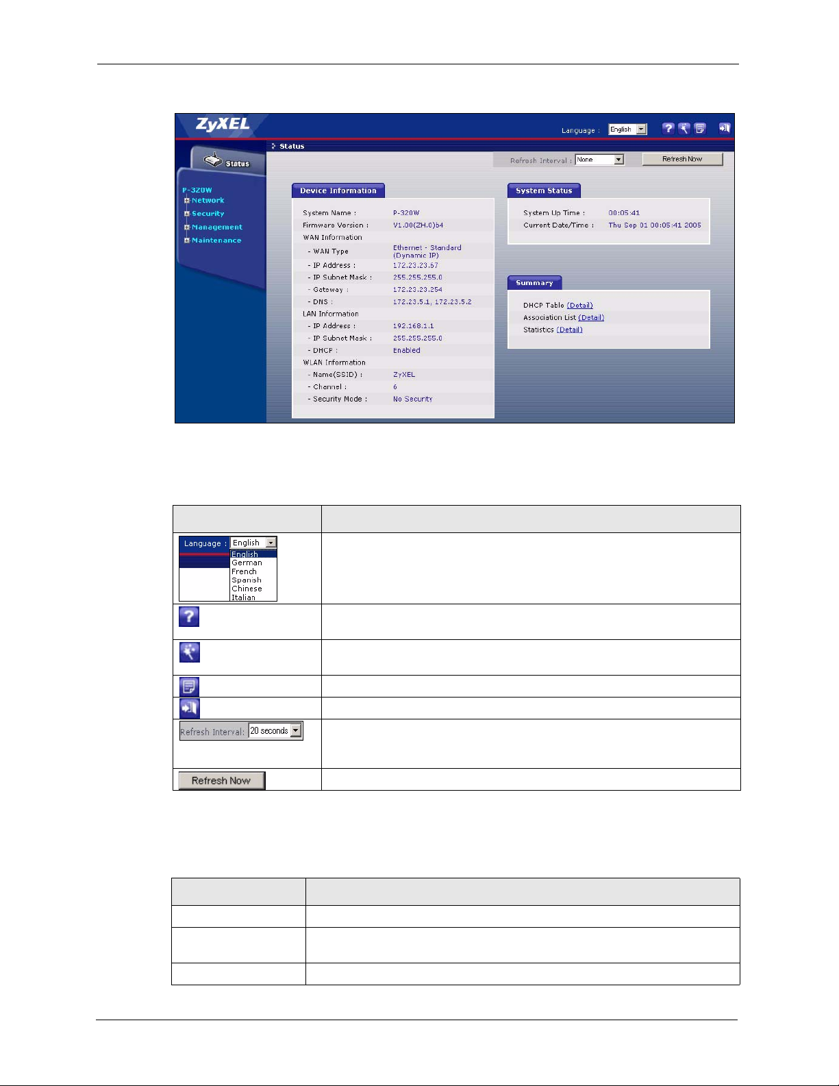
P-320W User’s Guide
Figure 8 Web Configurator Status Screen
The following table describes the icons shown in the Status screen.
Table 2 Status Screen Icon Key
ICON DESCRIPTION
Select a language from the drop-down list box to have the the web
configurator display in that language.
Click this icon to open a web help page relevent to the screen you are
currently configuring.
Click this icon to open the setup wizard. The Prestige has a connection
wizard and a bandwidth management wizard.
Click this icon to view copyright and a link for related product information.
Click this icon at any time to exit the web configurator.
Select a number of seconds or None from the drop-down list box to refresh
all screen statistics automatically at the end of every time interval or to not
refresh the screen statistics.
Click this button to refresh the status screen statistics.
The following table describes the labels shown in the Status screen.
Table 3 Web Configurator Status Screen
LABEL DESCRIPTION
Device Information
System Name This is the System Name you enter in the Maintenance, System, General
screen. It is for identification purposes.
Firmware Version This is the firmware version and the date created.
38 Chapter 2 Introducing the Web Configurator
Page 39

P-320W User’s Guide
Table 3 Web Configurator Status Screen
LABEL DESCRIPTION
WAN Information
- WAN Type This shows the encapsulation method (and service type) the Prestige is using.
- IP Address This shows the WAN port’s IP address.
- IP Subnet Mask This shows the WAN port’s subnet mask.
- Gateway This shows the gateway IP address.
- DNS This shows the IP address(es) of the DNS server(s).
LAN Information
- IP Address This shows the LAN port’s IP address.
- IP Subnet Mask This shows the LAN port’s subnet mask.
- DHCP This shows whether the Prestige acts as a DHCP server (Enabled) or not
(Disabled).
WLAN Information
- Name(SSID) This shows a descriptive name used to identify the Prestige in the wireless
LAN.
- Channel This shows the channel number which the Prestige uses over the wireless
- Security Mode This shows the level of wireless security the Prestige is using.
System Status
System Uptime This is the total time the Prestige has been on.
Current Date/Time This field displays your Prestige’s present date and time along with the
Summary
DHCP Table Use this screen to view current DHCP client information.
Association List Use this screen to view the wireless stations that are currently associated to
Stat istics Use this screen to view port status and packet specific statistics.
LAN.
difference from the Greenwich Mean Time (GMT) zone. The difference from
GMT is based on the time zone. It is also adjusted for Daylight Saving Time if
you set the Prestige to use it.
the Prestige.
2.4.1 Navigation Panel
After you enter the password, use the sub-menus on the navigation panel to configure Prestige
features. The navigation
The following table describes the sub-menus.
Table 4 Screens Summary
LINK TAB FUNCTION
Status This screen shows the Prestige’s general device and system status
information. Use this screen to access the wizard, and summary statistics
tables.
Network
Chapter 2 Introducing the Web Configurator 39
Page 40

P-320W User’s Guide
Table 4 Screens Summary
LINK TAB FUNCTION
Wireless LAN General Use this screen to configure wireless LAN.
OTIST This screen allows you to assign wireless clients the Prestige’s wireless
MAC Filter Use the MAC filter screen to configure the Prestige to block access to
Advanced This screen allows you to configure other advanced WLAN properties.
WAN Internet
Connection
Advanced Use this screen to configure DNS servers.
Traffic Redirect Use this screen to configure your traffic redirect properties and parameters.
LAN IP Use this screen to configure LAN settings.
DHCP Server General Use this screen to enable the Prestige’s DHCP server and to have DNS
Static DHCP Use this screen to assign IP addresses on the LAN to specific individual
Client List Use this screen to view current DHCP client information and to always
NAT General Use this screen to enable NAT.
Port Forwarding Use this screen to configure servers behind the Prestige.
Trigger Port Use this screen to change your Prestige’s port triggering settings.
Security
Firewall General Use this screen to activate/deactivate the firewall.
Services This screen shows a summary of the firewall rules, and allows you to edit/
Management
Static Route Static Route
Rules
Remote MGMT WWW Use this screen to configure through which interface(s) and from which IP
SNMP Use this screen to configure your Prestige’s settings for Simple Network
Security Use this screen to change your anti-probing settings.
UPnP General Use this screen to enable UPnP on the Prestige.
Maintenance
System General This screen contains administrative.
Dynamic DNS Use this screen to set up dynamic DNS.
Time Setting Use this screen to change your Prestige’s time and date.
Logs View Log Use this screen to view the logs for the categories that you selected.
Log Settings Use this screen to change your Prestige’s log settings.
security settings.
devices or block the devices from accessing the Prestige.
This screen allows you to configure ISP parameters, WAN IP address
assignment and the WAN MAC address.
servers assigned by the DHCP server.
computers based on their MAC addresses.
assign an IP address to a MAC address (and host name).
add a firewall rule.
Use this screen to configure IP static routes.
address(es) users can use HTTP to manage the Prestige.
Management Protocol management.
40 Chapter 2 Introducing the Web Configurator
Page 41
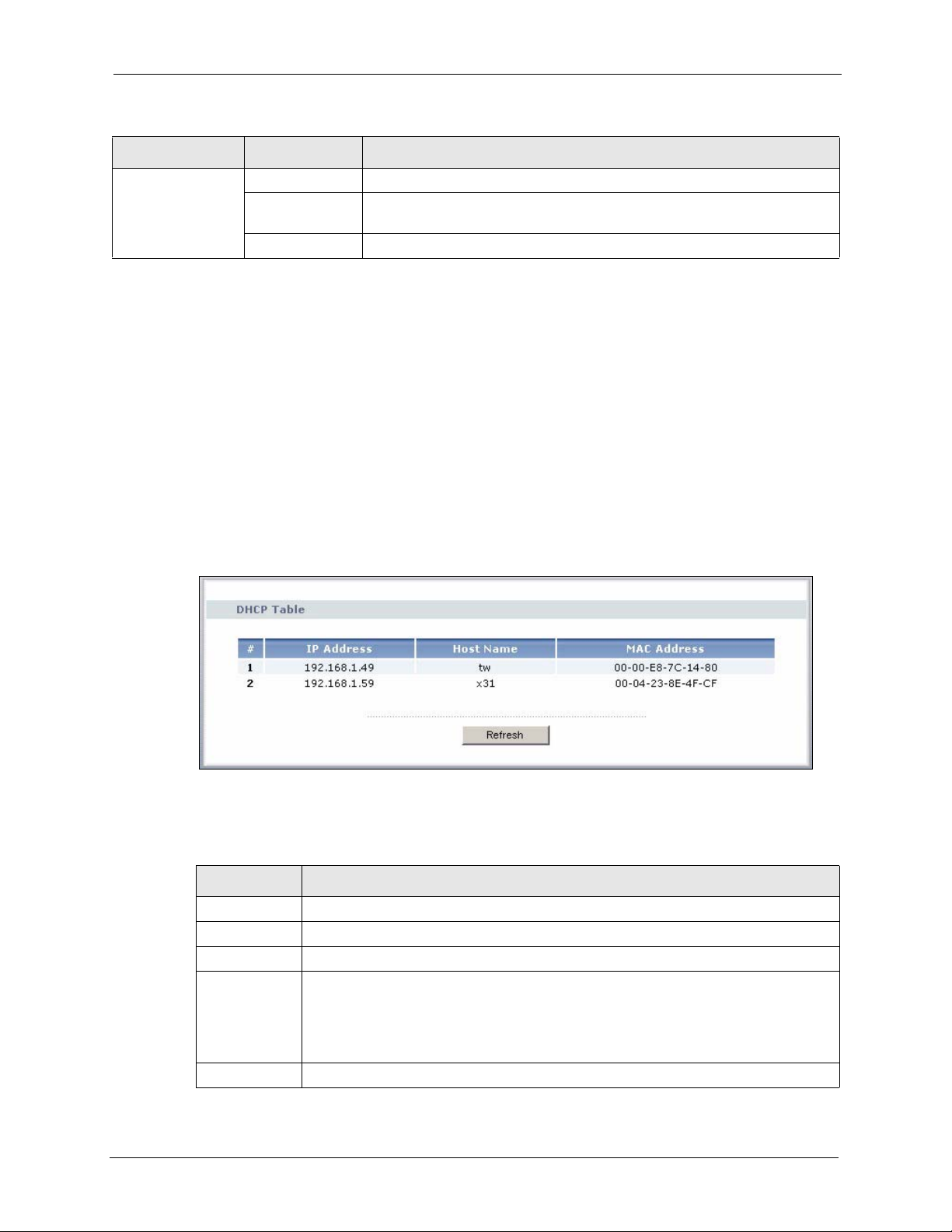
Table 4 Screens Summary
LINK TAB FUNCTION
Tools Firmware Use this screen to upload firmware to your Prestige.
Configuration Use this screen to backup and restore the configuration or reset the factory
defaults to your Prestige.
Restart This screen allows you to reboot the Prestige without turning the power off.
2.4.2 Summary: DHCP Table
DHCP (Dynamic Host Configuration Protocol, RFC 2131 and RFC 2132) allows individual
clients to obtain TCP/IP configuration at start-up from a server. You can configure the Prestige
as a DHCP server or disable it. When configured as a server, the Prestige provides the TCP/IP
configuration for the clients. If DHCP service is disabled, you must have another DHCP server
on your LAN, or else the computer must be manually configured.
Click the DHCP Table (Detail) hyperlink in the Status screen. Read-only information here
relates to your DHCP status. The DHCP table shows current DHCP client information
(including IP Address, Host Name and MAC Address) of all network clients using the
Prestige’s DHCP server.
P-320W User’s Guide
Figure 9 Summary: DHCP Table
The following table describes the labels in this screen.
Table 5 Summary: DHCP Table
LABEL DESCRIPTION
# This is the index number of the host computer.
IP Address This field displays the IP address relative to the # field listed above.
Host Name This field displays the computer host name.
MAC Address This field shows the MAC address of the computer with the name in the Host Name
field.
Every Ethernet device has a unique MAC (Media Access Control) address. The MAC
address is assigned at the factory and consists of six pairs of hexadecimal characters,
for example, 00:A0:C5:00:00:02.
Refresh Click Refresh to renew the screen.
Chapter 2 Introducing the Web Configurator 41
Page 42

P-320W User’s Guide
2.4.3 Summary: Association List
Click the Association List (Detail) hyperlink in the Status screen. View the wireless stations
that are currently associated to the Prestige in the Association List screen.
Figure 10 Summary: Association List
The following table describes the labels in this screen.
Table 6 Summary: Wireless Association List
LABEL DESCRIPTION
# This is the index number of an associated wireless station.
MAC Address This field displays the MAC address of an associated wireless station.
Association Time This field displays the time a wireless station first associated with the Prestige.
Refresh Click Refresh to redisplay the current screen.
2.4.4 Summary: Packet Statistics
Click the Statistics (Detail) hyperlink in the Status screen. Read-only information here
includes packet specific statistics. Also provided are "system up time" and "poll interval(s)".
The Poll Interval(s) field is configurable.
42 Chapter 2 Introducing the Web Configurator
Page 43
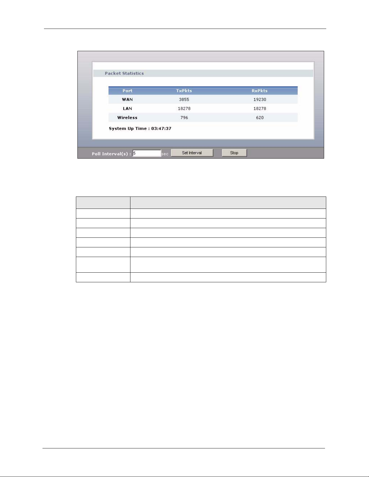
Figure 11 Summary: Packet Statistics
The following table describes the labels in this screen.
Table 7 Summary: Packet Statistics
P-320W User’s Guide
LABEL DESCRIPTION
Port This is the WAN, LAN or WLAN port.
TxPkts This is the number of transmitted packets on this port.
RxPkts This is the number of received packets on this port.
System Up Time This is the total time the Prestige has been on.
Poll Interval(s) Enter the time interval for refreshing statistics in this field.
Set Interval Click this button to apply the new poll interval you entered in the Poll Interval(s)
field.
Stop Click Stop to stop refreshing statistics, click Stop.
Chapter 2 Introducing the Web Configurator 43
Page 44

P-320W User’s Guide
44 Chapter 2 Introducing the Web Configurator
Page 45
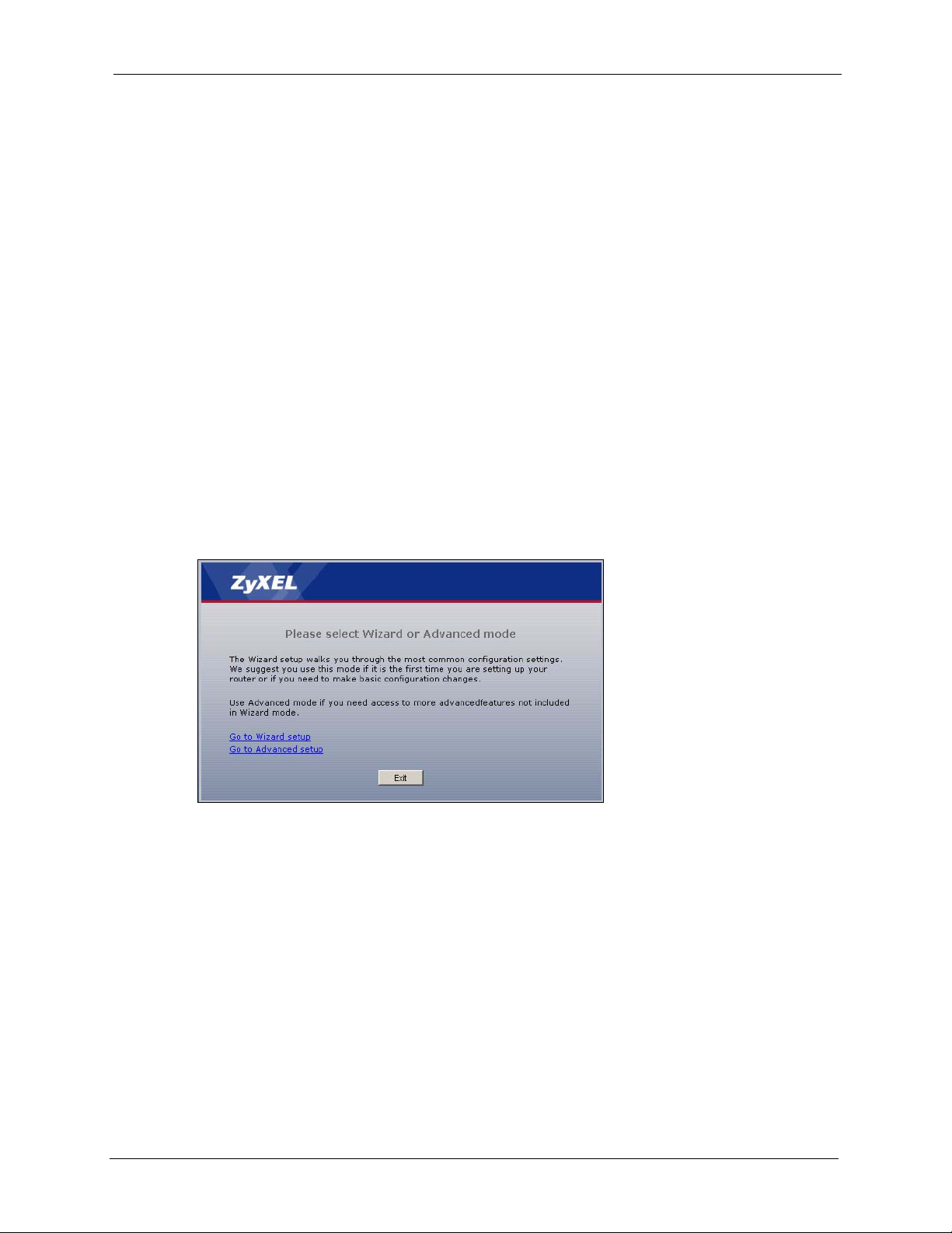
This chapter provides information on the Wizard setup screens in the web configurator.
3.1 Wizard Setup
The web configurator’s Wizard setup helps you configure your device to access the Internet.
Refer to your ISP (Internet Service Provider) checklist in the Quick Start Guide to know what
to enter in each field. Leave a field blank if you don’t have that information.
1 After you access the Prestige web configurator, click the Go to Wizard setup hyperlink.
You can click the Go to Advanced setup hyperlink to skip this wizard setup and
configure advanced features.
P-320W User’s Guide
CHAPTER 3
Connection Wizard
Figure 12 Select a Mode
2 Read the on-screen information and click Next.
Chapter 3 Connection Wizard 45
Page 46

P-320W User’s Guide
Figure 13 Welcome to the Connection Wizard
3.2 Connection Wizard: STEP 1: System Information
System Information contains administrative and system-related information.
3.2.1 System Name
System Name is for identification purposes. However, because some ISPs check this name
you should enter your computer's "Computer Name".
• In Windows 95/98 click Start, Settings, Control Panel, Network. Click the
Identification tab, note the entry for the Computer Name field and enter it as the System
Name.
• In Windows 2000, click Start, Settings and Control Panel and then double-click
System. Click the Network Identification tab and then the Properties button. Note the
entry for the Computer name field and enter it as the System Name.
• In Windows XP, click Start, My Computer, View system information and then click
the Computer Name tab. Note the entry in the Full computer name field and enter it as
the Prestige System Name.
3.2.2 Domain Name
The Domain Name entry is what is propagated to the DHCP clients on the LAN. If you leave
this blank, the domain name obtained by DHCP from the ISP is used. While you must enter
the host name (System Name) on each individual computer, the domain name can be assigned
from the Prestige via DHCP.
Click Next to configure the Prestige for Internet access.
46 Chapter 3 Connection Wizard
Page 47
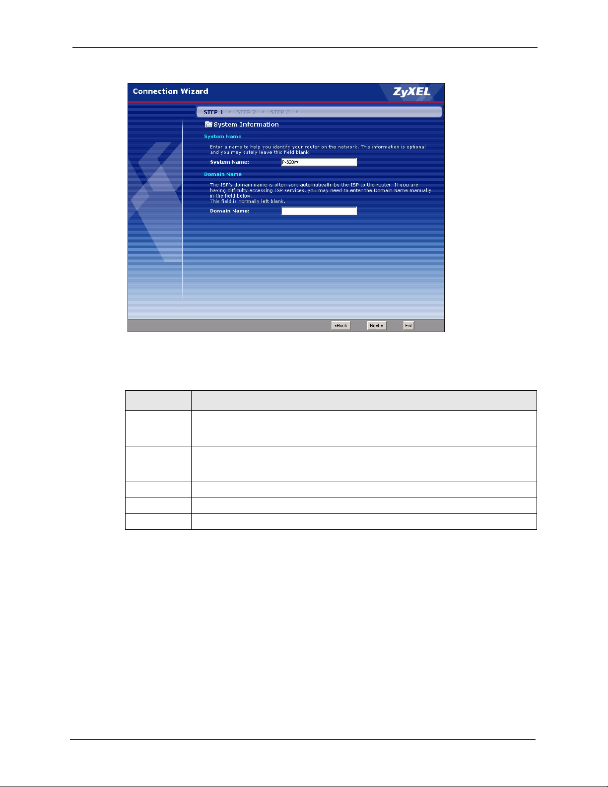
Figure 14 Connection Wizard: STEP 1: System Information
P-320W User’s Guide
The following table describes the labels in this screen.
Table 8 Connection Wizard: STEP 1: System Information
LABEL DESCRIPTION
System Name System Name is a unique name to identify the Prestige in an Ethernet network. Enter a
descriptive name. This name can be up to 30 alphanumeric characters long. Spaces
are not allowed, but dashes "-" and underscores "_" are accepted.
Domain Name Type the domain name (if you know it) here. If you leave this field blank, the ISP may
assign a domain name via DHCP. The domain name entered by you is given priority
over the ISP assigned domain name.
Back Click Back to display the previous screen.
Next Click Next to proceed to the next screen.
Exit Click Exit to close the wizard screen without saving.
3.3 Connection Wizard: STEP 2: Wireless LAN
Set up your wireless LAN using the following screen.
Chapter 3 Connection Wizard 47
Page 48

P-320W User’s Guide
Figure 15 Connection Wizard: STEP 2: Wireless LAN
The following table describes the labels in this screen.
Table 9 Connection Wizard: STEP 2: Wireless LAN
LABEL DESCRIPTION
Name(SSID) Enter a descriptive name (up to 32 printable 7-bit ASCII characters) for the wireless
LAN.
If you change this field on the Prestige, make sure all wireless stations use the same
SSID in order to access the network.
Channel
Selection
Security Select a Security level from the drop-down list box.
Back Click Back to display the previous screen.
Next Click Next to proceed to the next screen.
Exit Click Exit to close the wizard screen without saving.
The range of radio frequencies used by IEEE 802.11b/g wireless devices is called a
channel. Select a channel ID that is not already in use by a neighboring device.
Choose Auto (WPA-PSK with self-generated key) to use WPA-PSK security with a
default Pre-Shared Key and only if your wireless clients support WPA-PSK. If you
choose this option, skip directly to
Choose None to have no wireless LAN security configured. If you do not enable any
wireless security on your Prestige, your network is accessible to any wireless
networking device that is within range. If you choose this option, skip directly to section
3.3.3.
Choose Basic (WEP) security if you want to configure WEP Encryption parameters. If
you choose this option, go directly to
Choose Extend (WPA-PSK with customized key) security to configure a Pre-Shared
Key. Choose this option only if your wireless clients support WPA-PSK or WPA2-PSK
respectively. If you choose this option, skip directly to
Section 3.3.3 on page 51.
Section 3.3.1 on page 49.
Section 3.3.2 on page 50.
48 Chapter 3 Connection Wizard
Page 49
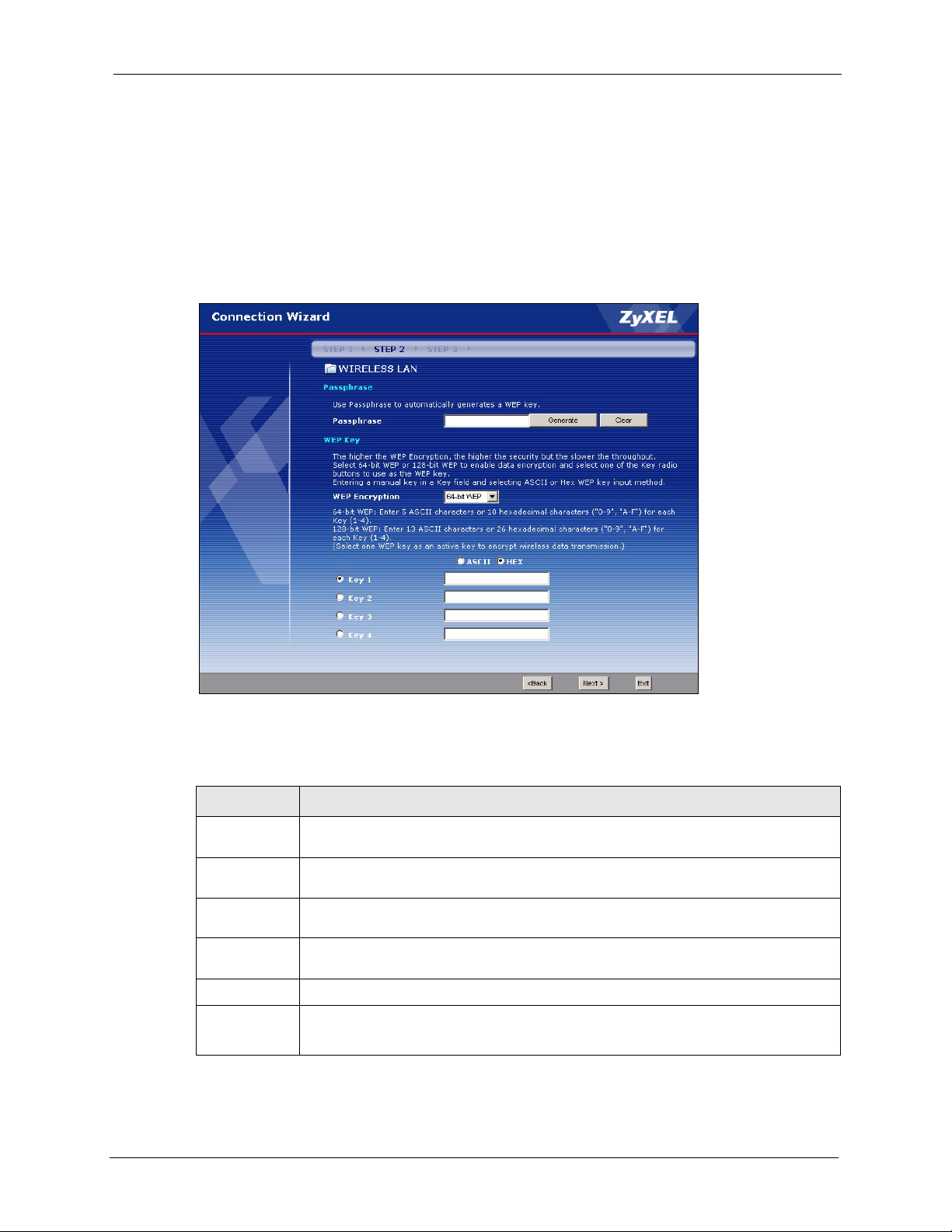
Note: The wireless stations and Prestige must use the same SSID, channel ID and
WEP encryption key (if WEP is enabled), WPA-PSK (if WPA-PSK is enabled)
for wireless communication.
3.3.1 Basic(WEP) Security
Choose Basic(WEP) to setup WEP Encryption parameters.
Figure 16 Basic(WEP) Security
P-320W User’s Guide
The following table describes the labels in this screen.
Table 10 Basic(WEP) Security
LABEL DESCRIPTION
Passphrase Type a Passphrase (up to 32 printable characters) and click Generate. The Prestige
Generate After you enter the passphrase, click Generate to have the Prestige generates four
Clear Click Clear to discard the passphrase you configured in the Passphrase field and the
WEP
Encryption
Chapter 3 Connection Wizard 49
automatically generates four different WEP keys.
different WEP keys automatically.
WEP key(s) generated automatically or maually configured.
Select 64-bit WEP or 128-bit WEP to allow data encryption.
ASCII Select this option in order to enter ASCII characters as the WEP keys.
HEX Select this option to enter hexadecimal characters as the WEP keys.
The preceding “0x” is entered automatically.
Page 50
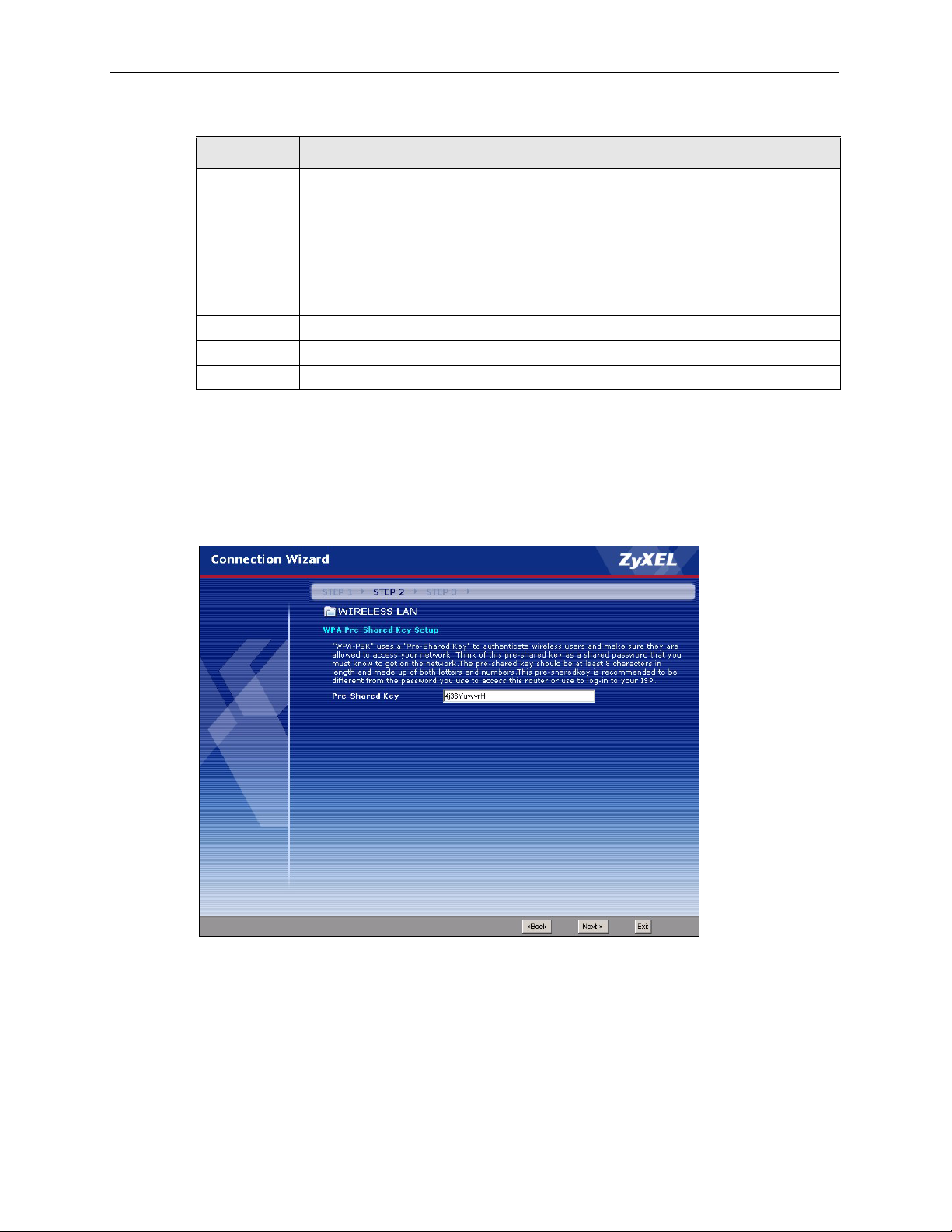
P-320W User’s Guide
Table 10 Basic(WEP) Security
LABEL DESCRIPTION
Key 1 to Key 4 The WEP keys are used to encrypt data. Both the Prestige and the wireless stations
must use the same WEP key for data transmission.
If you chose 64-bit WEP, then enter any 5 ASCII characters or 10 hexadecimal
characters ("0-9", "A-F").
If you chose 128-bit WEP, then enter 13 ASCII characters or 26 hexadecimal
characters ("0-9", "A-F").
You must configure at least one key, only one key can be activated at any one time.
The default key is key 1.
Back Click Back to display the previous screen.
Next Click Next to proceed to the next screen.
Exit Click Exit to close the wizard screen without saving.
3.3.2 Extend(WPA-PSK) Security
Choose Extend(WPA-PSK) security in the Wireless LAN setup screen to set up a Pre-
Shared Key.
Figure 17 Extend(WPA-PSK) Security
50 Chapter 3 Connection Wizard
Page 51
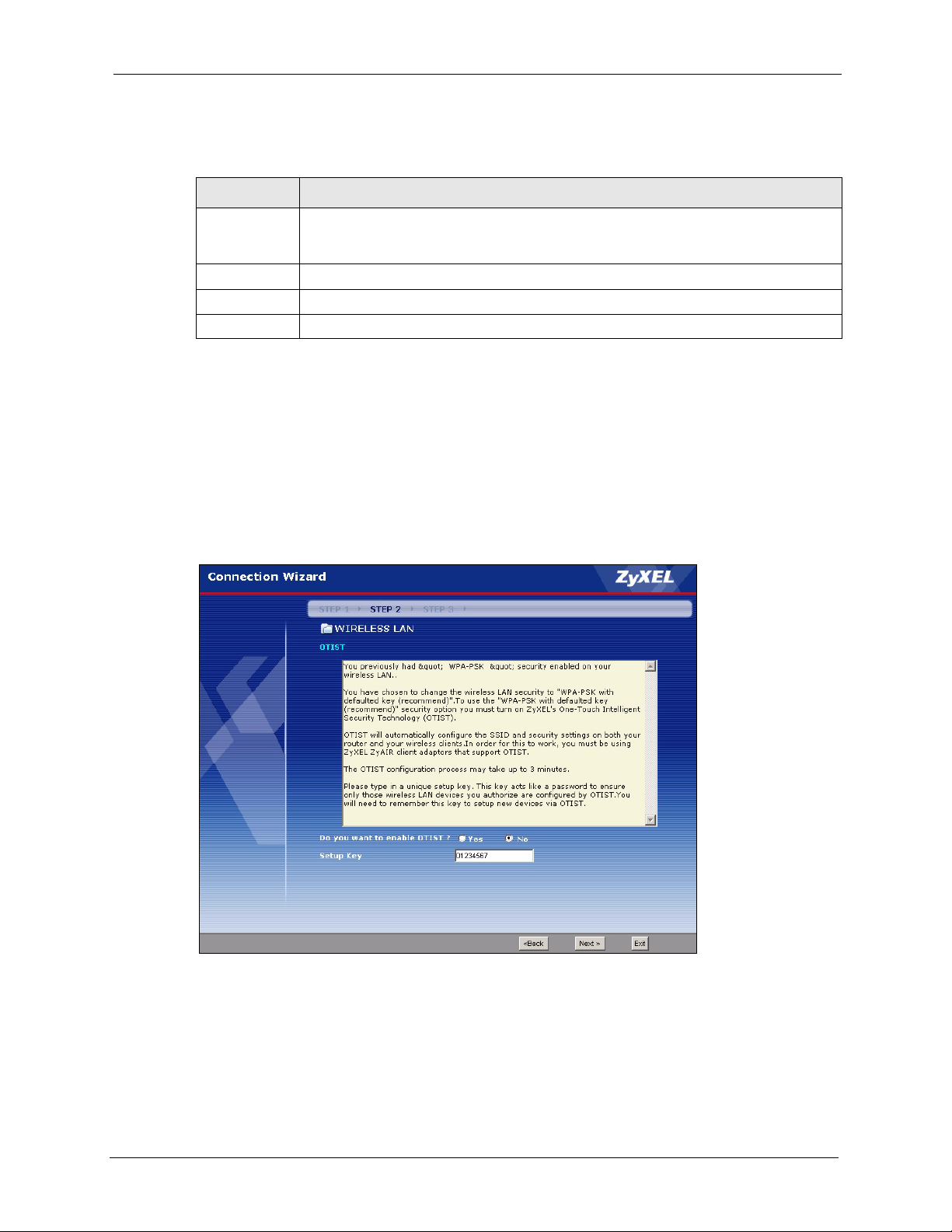
The following table describes the labels in this screen.
Tabl e 11 Extend(WPA-PSK) Security
LABEL DESCRIPTION
P-320W User’s Guide
Pre-Shared
Key
Back Click Back to display the previous screen.
Next Click Next to proceed to the next screen.
Exit Click Exit to close the wizard screen without saving.
3.3.3 OTIST
The following screen allows you to enable Prestige One-Touch Intelligent Security
Technology (OTIST). One-Touch Intelligent Security Technology (OTIST) allows your
Prestige to assign wireless clients the Prestige’s SSID and static WEP or WPA-PSK
encryption settings. The wireless client must also support OTIST and have OTIST enabled.
See
Figure 18 OTIST
Type from 8 to 63 case-sensitive ASCII characters. You can set up the most secure
wireless connection by configuring WPA in the wireless LAN screens. You need to
configure an authentication server to do this.
Section 4.5 on page 72 for more information.
Chapter 3 Connection Wizard 51
Page 52
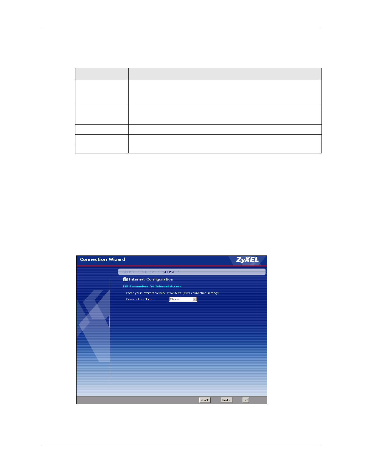
P-320W User’s Guide
The following table describes the labels in this screen.
Table 12 OTIST
LABEL DESCRIPTION
Do you want to
enable OTIST?
Setup Key The default OTIST Setup Key is “01234567”. This key can be changed in the
Back Click Back to display the previous screen.
Next Click Next to proceed to the next screen.
Exit Click Exit to close the wizard screen without saving.
Select the Yes radio button and click Next to proceed with the setup wizard and
enable OTIST only when you click Finish in the final wizard screen.
Click No and then Next to proceed to the following screen.
web configurator. Be sure to use the same OTIST Setup Key on the Prestige
and wireless clients.
Refer to the chapter on wireless LAN for more information.
3.4 Connection Wizard: STEP 3: Internet Configuration
The Prestige offers three Internet connection types. They are Ethernet, PPP over Ethernet or
PPTP. The wizard attempts to detect which WAN connection type you are using. If the wizard
does not detect a connection type, you must select one from the drop-down list box. Check
with your ISP to make sure you use the correct type.
Figure 19 Connection Wizard: STEP 3: WAN Connection Type.
52 Chapter 3 Connection Wizard
Page 53
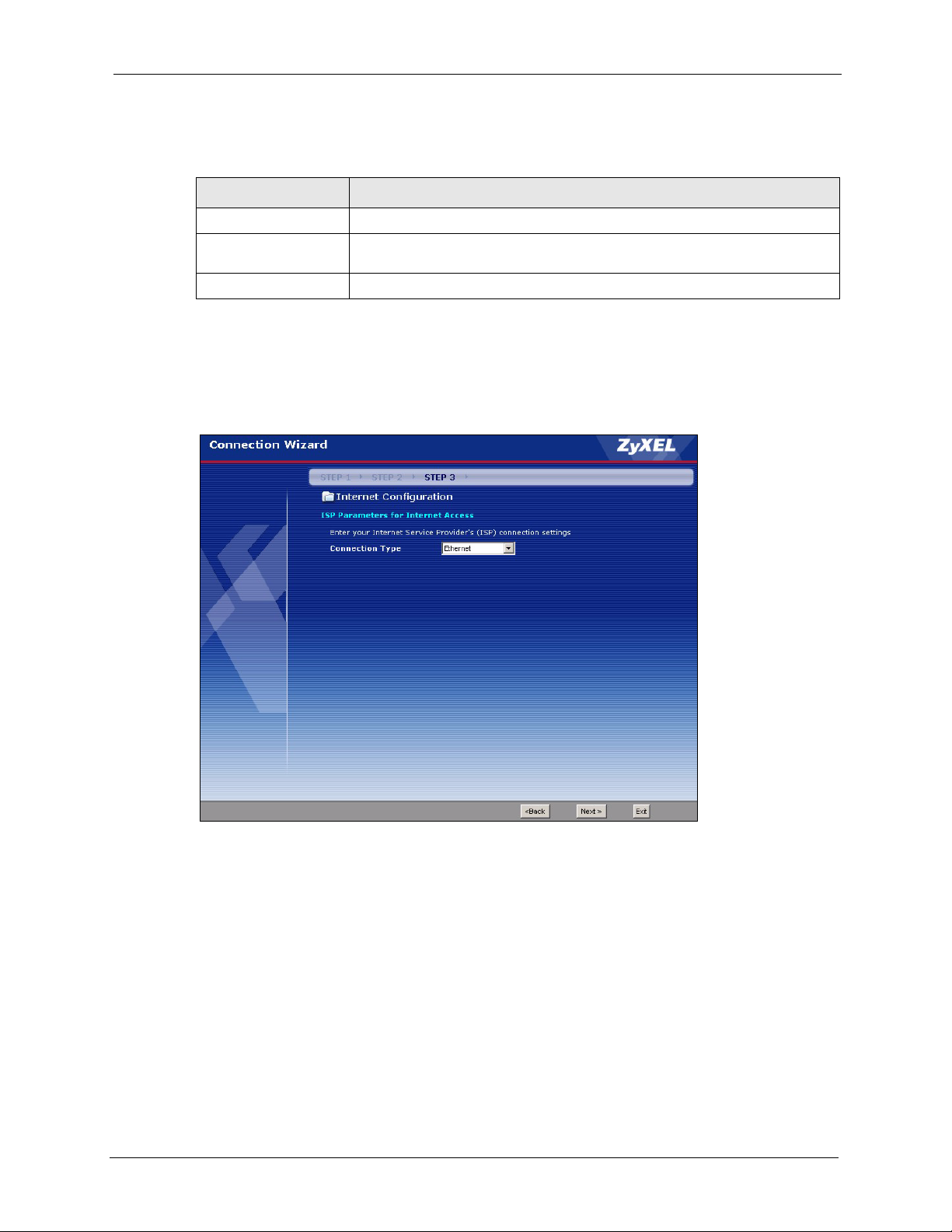
The following table describes the labels in this screen,
Table 13 Connection Wizard: STEP 3: WAN Connection Type
CONNECTION TYPE DESCRIPTION
Ethernet Select the Ethernet option when the WAN port is used as a regular Ethernet.
PPPoE Select the PPP over Ethernet option for a dial-up connection. If your ISP
gave you a an IP address and/or subnet mask, then select PPTP.
PPTP Select the PPTP option for a dial-up connection.
3.4.1 Ethernet Connection Type
Choose Ethernet when the WAN port is used as a regular Ethernet.
Figure 20 Ethernet Connection Type
P-320W User’s Guide
3.4.2 PPPoE Connection Type
Point-to-Point Protocol over Ethernet (PPPoE) functions as a dial-up connection. PPPoE is an
IETF (Internet Engineering Task Force) standard specifying how a host personal computer
interacts with a broadband modem (for example DSL, cable, wireless, etc.) to achieve access
to high-speed data networks.
For the service provider, PPPoE offers an access and authentication method that works with
existing access control systems (for instance, RADIUS).
Chapter 3 Connection Wizard 53
Page 54

P-320W User’s Guide
One of the benefits of PPPoE is the ability to let end users access one of multiple network
services, a function known as dynamic service selection. This enables the service provider to
easily create and offer new IP services for specific users.
Operationally, PPPoE saves significant effort for both the subscriber and the ISP/carrier, as it
requires no specific configuration of the broadband modem at the subscriber’s site.
By implementing PPPoE directly on the Prestige (rather than individual computers), the
computers on the LAN do not need PPPoE software installed, since the Prestige does that part
of the task. Furthermore, with NAT, all of the LAN's computers will have Internet access.
Refer to the appendix for more information on PPPoE.
Figure 21 PPPoE Connection Type
The following table describes the labels in this screen.
Table 14 PPPoE Connection Type
LABEL DESCRIPTION
ISP Parameter for Internet Access
Service Name Type the name of your service provider.
User Name Type the user name given to you by your ISP.
Password Type the password associated with the user name above.
Next Click Next to continue.
Back Click Back to return to the previous screen.
Exit Click Exit to close the wizard screen without saving.
54 Chapter 3 Connection Wizard
Page 55
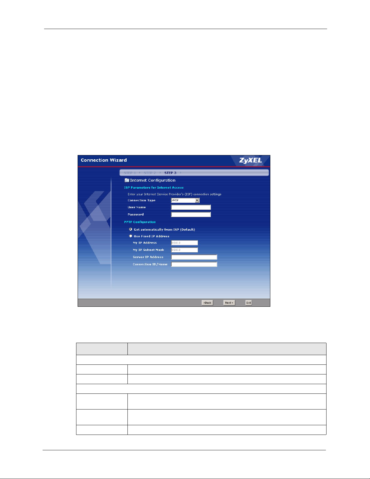
3.4.3 PPTP Connection Type
Point-to-Point Tunneling Protocol (PPTP) is a network protocol that enables transfers of data
from a remote client to a private server, creating a Virtual Private Network (VPN) using TCP/
IP-based networks.
PPTP supports on-demand, multi-protocol, and virtual private networking over public
networks, such as the Internet.
Refer to the appendix for more information on PPTP.
Note: The Prestige supports one PPTP server connection at any given time.
Figure 22 PPTP Connection Type
P-320W User’s Guide
The following table describes the fields in this screen
Table 15 PPTP Connection Type
LABEL DESCRIPTION
ISP Parameters for Internet Access
User Name Type the user name given to you by your ISP.
Password Type the password associated with the User Name above.
PPTP Configuration
Get automatically
from ISP
Use fixed IP
address
My IP Address Type the (static) IP address assigned to you by your ISP.
Chapter 3 Connection Wizard 55
Select this radio button if your ISP did not assign you a fixed IP address.
Select this radio button, provided by your ISP to give the Prestige a fixed, unique
IP address.
Page 56
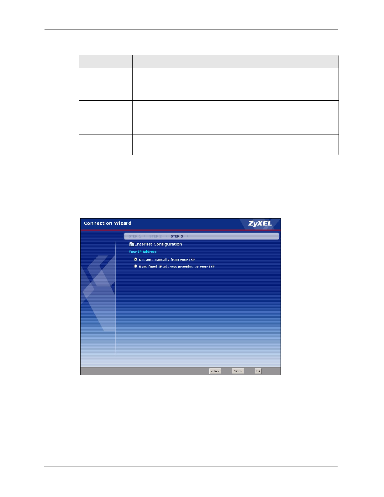
P-320W User’s Guide
Table 15 PPTP Connection Type
LABEL DESCRIPTION
My IP Subnet
Mask
Server IP
Address
Connection ID/
Name
Back Click Back to return to the previous screen.
Next Click Next to continue.
Exit Click Exit to close the wizard screen without saving.
3.4.4 Your IP Address
The following wizard screen allows you to assign a fixed IP address or give the Prestige an
automatically assigned IP address depending on your ISP.
Figure 23 Your IP Address
Type the subnet mask assigned to you by your ISP (if given).
Type the IP address of the PPTP server.
Enter the connection ID or connection name in this field. It must follow the "c:id"
and "n:name" format. For example, C:12 or N:My ISP.
This field is optional and depends on the requirements of your ISP.
56 Chapter 3 Connection Wizard
Page 57

The following table describes the labels in this screen
Table 16 Your IP Address
LABEL DESCRIPTION
P-320W User’s Guide
Get automatically from
ISP
Use fixed IP address
provided by your ISP
Back Click Back to return to the previous screen.
Next Click Next to continue.
Exit Click Exit to close the wizard screen without saving.
3.4.5 WAN MAC Address
Every Ethernet device has a unique MAC (Media Access Control) address. The MAC address
is assigned at the factory and consists of six pairs of hexadecimal characters, for example, 00A0-C5-00-00-02.
You can configure the WAN port's MAC address by either using the factory default or cloning
the MAC address from a computer on your LAN. Once it is successfully configured, the
address will be copied to the "rom" file (ZyNOS configuration file). It will not change unless
you change the setting or upload a different "rom" file.
Table 17 Example of Network Properties for LAN Servers with Fixed IP Addresses
Select this option If your ISP did not assign you a fixed IP address. This is
the default selection.
Select this option If the ISP assigned a fixed IP address. The fixed IP
address should be in the same subnet as your broadband modem or
router.
Choose an IP address 192.168.1.2-192.168.1.32; 192.168.1.65-192.168.1.254.
Subnet mask 255.255.255.0
Gateway (or default route) 192.168.1.1(Prestige LAN IP)
This screen allows users to configure the WAN port's MAC address by either using the factory
default or cloning the MAC address from a computer on your LAN.
Chapter 3 Connection Wizard 57
Page 58

P-320W User’s Guide
Figure 24 WAN MAC Address
The following table describes the fields in this screen.
Table 18 WAN MAC Address
LABEL DESCRIPTION
Factory Default Select Factory Default to use the factory assigned default MAC address.
Spoof this
computer’s MAC
address
MAC Address Enter the MAC address of the computer on the LAN whose MAC address you
Back Click Back to return to the previous screen.
Next Click Next to continue.
Exit Click Exit to close the wizard screen without saving.
Select this option and click Clone MAC to clone the MAC address in the MAC
Address field.
Once it is successfully configured, the address will be copied to the rom file
(ZyNOS configuration file). It will not change unless you change the setting or
upload a different ROM file. It is advisable to clone the MAC address from a
computer on your LAN even if your ISP does not presently require MAC address
authentication.
want to clone.
3.4.6 Connection Wizard Complete
Follow the on-screen instructions and click Next.
58 Chapter 3 Connection Wizard
Page 59
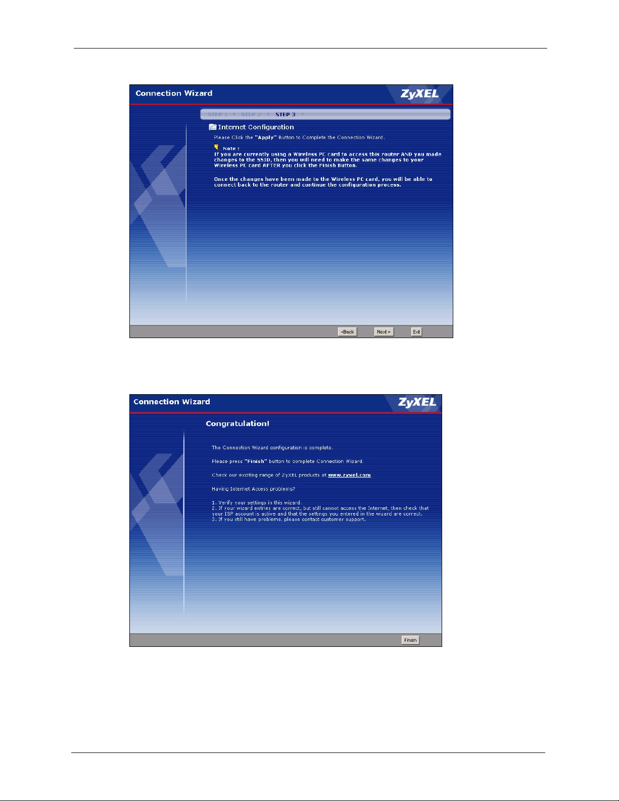
Figure 25 Connection Wizard Complete
P-320W User’s Guide
Click Finish to complete the wizard setup and save your configuration.
Figure 26 Connection Wizard: Congratulation
Well done! You have successfully set up your Prestige to operate on your network and access
the Internet.
Chapter 3 Connection Wizard 59
Page 60

P-320W User’s Guide
60 Chapter 3 Connection Wizard
Page 61

This chapter discusses how to configure Wireless LAN.
4.1 Introduction
A wireless LAN can be as simple as two computers with wireless LAN adapters
communicating in a peer-to-peer network or as complex as a number of computers with
wireless LAN adapters communicating through access points which bridge network traffic to
the wired LAN.
Note: See the WLAN appendix for more detailed information on WLANs.
P-320W User’s Guide
CHAPTER 4
Wireless LAN
4.2 Wireless Security Overview
Wireless security is vital to your network to protect wireless communication between wireless
stations, access points and the wired network.
Wireless security methods available on the Prestige are data encryption, wireless client
authentication, restricting access by device MAC address and hiding the Prestige identity.
4.2.1 Encryption
• Use WPA security if you have WPA-aware wireless clients and a RADIUS server. WPA
has user authentication and improved data encryption over WEP.
• Use WPA-PSK if you have WPA-aware wireless clients but no RADIUS server.
• If you don’t have WPA-aware wireless clients, then use WEP key encrypting. A higher
bit key offers better security at a throughput trade-off. You can use Passphrase to
automatically generate 64-bit or 128-bit WEP keys or manually enter 64-bit or 128-bit
WEP keys.
4.2.2 Authentication
WPA has user authentication and you can also configure IEEE 802.1x to use a RADIUS server
to authenticate wireless clients before joining your network.
• Use RADIUS authentication if you have a RADIUS server. See the appendices for
information on protocols used when a client authenticates with a RADIUS server via the
Prestige.
Chapter 4 Wireless LAN 61
Page 62

P-320W User’s Guide
4.2.3 Restricted Access
The MAC Filter screen allows you to configure the AP to give exclusive access to devices
(Allow) or exclude them from accessing the AP (Deny).
4.2.4 Hide Prestige Identity
If you hide the ESSID, then the Prestige cannot be seen when a wireless client scans for local
APs. The trade-off for the extra security of “hiding” the Prestige may be inconvenient for
some valid WLAN clients.
4.2.5 Using OTIST
In a wireless network, the wireless clients must have the same SSID and security settings as
the access point (AP) or wireless router (we will refer to both as “AP” here) in order to
associate with it. Traditionally this meant that you had to configure the settings on the AP and
then manually configure the exact same settings on each wireless client.
OTIST (One-Touch Intelligent Security Technology) allows you to transfer your AP’s SSID
and WEP or WPA-PSK security settings to wireless clients that support OTIST and are within
transmission range. You can also choose to have OTIST generate a WPA-PSK key for you if
you didn’t configure one manually.
Note: OTIST replaces the pre-configured wireless settings on the wireless clients.
4.3 Configuring Wireless LAN on the Prestige
1 Configure the SSID and Security Mode in the Wireless screen. If you configure WEP,
you can’t configure WPA or WPA-PSK.
2 Use the MAC Filter screen to restrict access to your wireless network by MAC address.
3 If you have OTIST-enabled clients, configure OTIST in the OTIST screen. OTIST
transfers device SSID and WEP or WPA-PSK key settings (if enabled) to wireless
clients.
62 Chapter 4 Wireless LAN
Page 63

The following figure shows the relative effectiveness of these wireless security methods
available on your Prestige.
Table 19 ZyAIR Wireless Security Levels
Security Level Security Type
Least Secure
Most Secure
Unique SSID (Default)
Unique SSID with Hide SSID Enabled
MAC Address Filtering
WEP Encryption
IEEE802.1x EAP with RADIUS Server Authentication
Wi-Fi Protected Access (WPA)
Note: You must enable the same wireless security settings on the Prestige and on all
wireless clients that you want to associate with it.
4.4 General Wireless LAN Screen
P-320W User’s Guide
Note: If you are configuring the Prestige from a computer connected to the wireless
LAN and you change the Prestige’s SSID or WEP settings, you will lose your
wireless connection when you press Apply to confirm. You must then change
the wireless settings of your computer to match the Prestige’s new settings.
Click the Wireless LAN link under Network to open the General screen.
Figure 27 Wireless: General
Chapter 4 Wireless LAN 63
Page 64

P-320W User’s Guide
The following table describes the general wireless LAN labels in this screen.
Table 20 Wireless: General
LABEL DESCRIPTION
Enable
Wireless LAN
Name(SSID) (Service Set IDentity) The SSID identifies the Service Set with which a wireless
Click the check box to activate wireless LAN.
station is associated. Wireless stations associating to the access point (AP) must
have the same SSID. Enter a descriptive name (up to 32 printable 7-bit ASCII
characters) for the wireless LAN.
Note: If you are configuring the Prestige from a computer connected
to the wireless LAN and you change the Prestige’s SSID or
WEP settings, you will lose your wireless connection when you
press Apply to confirm. You must then change the wireless
settings of your computer to match the Prestige’s new settings.
Hide SSID Select this check box to hide the SSID in the outgoing beacon frame so a station
cannot obtain the SSID through passive scanning using a site survey tool.
Channel
Selection
Apply Click Apply to save your changes back to the Prestige.
Reset Click Reset to reload the previous configuration for this screen.
Set the operating frequency/channel depending on your particular region.
Select a channel from the drop-down list box.
Refer to the Connection Wizard chapter for more information on channels.
See the rest of this chapter for information on the other labels in this screen.
4.4.1 No Security
Select No Security to allow wireless stations to communicate with the access points without
any data encryption.
Note: If you do not enable any wireless security on your Prestige, your network is
accessible to any wireless networking device that is within range.
64 Chapter 4 Wireless LAN
Page 65
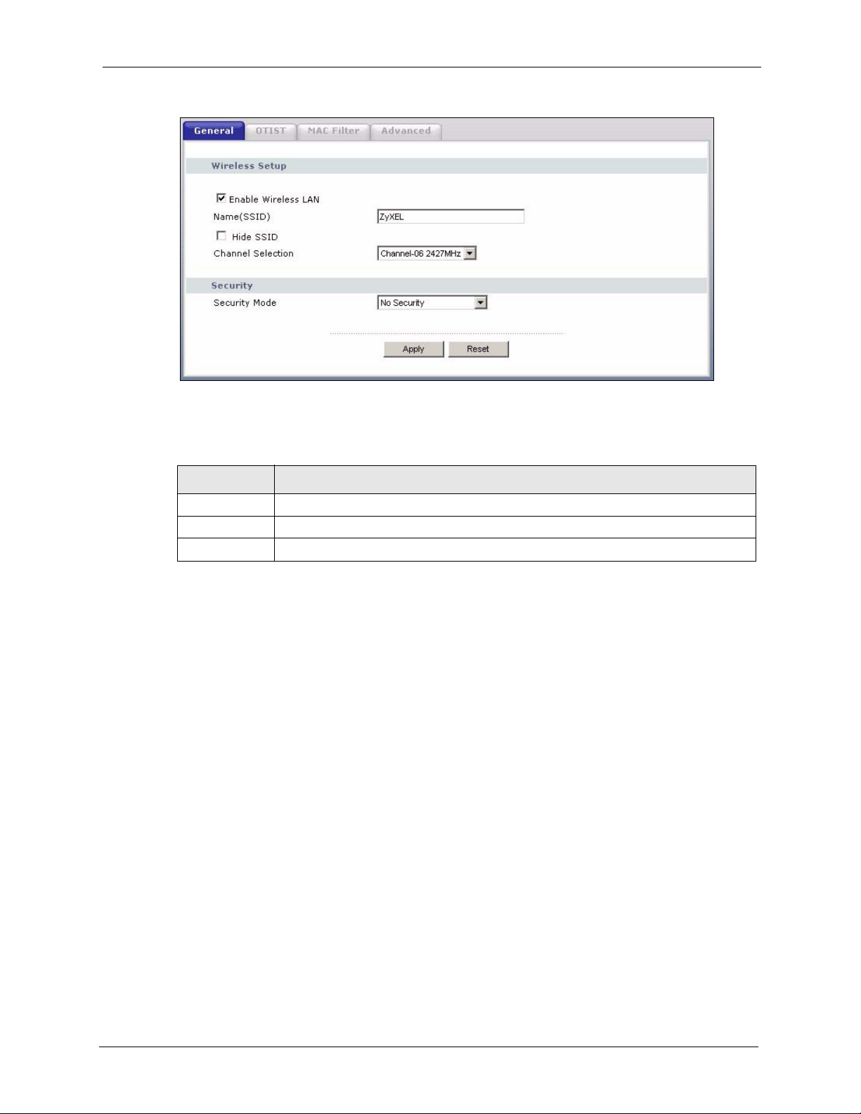
Figure 28 Wireless: No Security
The following table describes the labels in this screen.
Table 21 Wireless No Security
P-320W User’s Guide
LABEL DESCRIPTION
Security Mode Choose No Security from the drop-down list box.
Apply Click Apply to save your changes back to the Prestige.
Reset Click Reset to reload the previous configuration for this screen.
4.4.2 WEP Encryption
WEP encryption scrambles the data transmitted between the wireless stations and the access
points to keep network communications private. It encrypts unicast and multicast
communications in a network. Both the wireless stations and the access points must use the
same WEP key.
Your Prestige allows you to configure up to four 64-bit or 128-bit WEP keys but only one key
can be enabled at any one time.
In order to configure and enable WEP encryption; click Wireless LAN and Wireless to
display the General screen.
Select Static WEP from the Security Mode list.
Chapter 4 Wireless LAN 65
Page 66
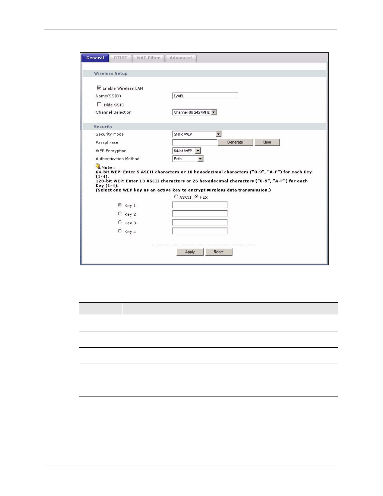
P-320W User’s Guide
Figure 29 Wireless: Static WEP Encryption
The following table describes the wireless LAN security labels in this screen.
Table 22 Wireless: Static WEP Encryption
LABEL DESCRIPTION
Passphrase Enter a Passphrase (up to 32 printable characters) and clicking Generate. The
Prestige automatically generates four different WEP keys.
Generate After you enter the passphrase, click Generate to have the Prestige generates four
different WEP keys automatically.
Clear Click Clear to discard the passphrase you configured in the Passphrase field and the
WEP
Encryption
Authentication
Method
ASCII
Hex
WEP key(s) generated automatically or maually configured.
Select 64-bit WEP or 128-bit WEP to enable data encryption.
Select Auto, Open System or Shared Key from the drop-down list box.
Select this option in order to enter ASCII characters as the WEP key.
Select this option in order to enter hexadecimal characters as a WEP key.
The preceding "0x", that identifies a hexadecimal key, is entered automatically.
66 Chapter 4 Wireless LAN
Page 67

Table 22 Wireless: Static WEP Encryption
LABEL DESCRIPTION
Key 1 to Key 4 The WEP keys are used to encrypt data. Both the Prestige and the wireless stations
must use the same WEP key for data transmission.
If you chose 64-bit WEP, then enter any 5 ASCII characters or 10 hexadecimal
characters ("0-9", "A-F").
If you chose 128-bit WEP, then enter 13 ASCII characters or 26 hexadecimal
characters ("0-9", "A-F").
You must configure at least one key, only one key can be activated at any one time.
The default key is key 1.
Apply Click Apply to save your changes back to the Prestige.
Reset Click Reset to reload the previous configuration for this screen.
4.4.3 Introduction to WPA
Wi-Fi Protected Access (WPA) is a subset of the IEEE 802.11i standard. WPA is preferred to
WEP as WPA has user authentication and improved data encryption. See the appendix for
more information on WPA user authentication and WPA encryption.
P-320W User’s Guide
If both an AP and the wireless clients support WPA and you have an external RADIUS server,
use WPA for stronger data encryption. If you don't have an external RADIUS server, you
should use WPA-PSK (WPA-Pre-Shared Key) that only requires a single (identical) password
entered into each access point, wireless gateway and wireless client. As long as the passwords
match, a wireless client will be granted access to a WLAN.
4.4.4 WPA-PSK Application Example
A WPA-PSK application looks as follows.
1 First enter identical passwords into the AP and all wireless clients. The Pre-Shared Key
(PSK) must consist of between 8 and 63 ASCII characters (including spaces and
symbols).
2 The AP checks each wireless client's password and (only) allows it to join the network if
the password matches.
3 The AP derives and distributes keys to the wireless clients.
4 The AP and wireless clients use the TKIP encryption process to encrypt data exchanged
between them.
Chapter 4 Wireless LAN 67
Page 68
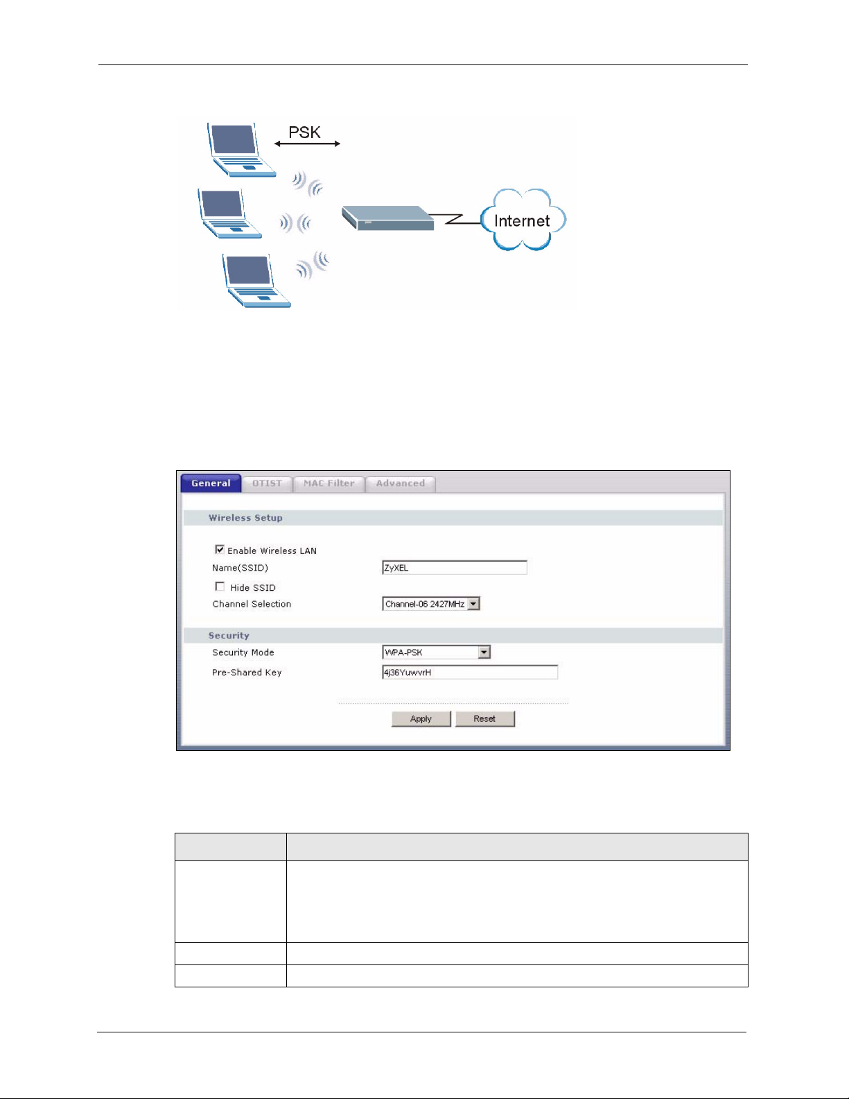
P-320W User’s Guide
Figure 30 WPA-PSK Authentication
4.4.5 WPA-PSK Authentication Screen
In order to configure and enable WPA-PSK Authentication; click the Wireless LAN link
under Network to display the General screen. Select WPA-PSK from the Security Mode
list.
Figure 31 Wireless: WPA-PSK
The following table describes the labels in this screen.
Table 23 Wireless: WPA-PSK
LABEL DESCRIPTION
Pre-Shared Key The encryption mechanisms used for WPA and WPA-PSK are the same. The only
difference between the two is that WPA-PSK uses a simple common password,
instead of user-specific credentials.
Type a pre-shared key from 8 to 63 case-sensitive ASCII characters (including
spaces and symbols).
Apply Click Apply to save your changes back to the Prestige.
Reset Click Reset to reload the previous configuration for this screen.
68 Chapter 4 Wireless LAN
Page 69
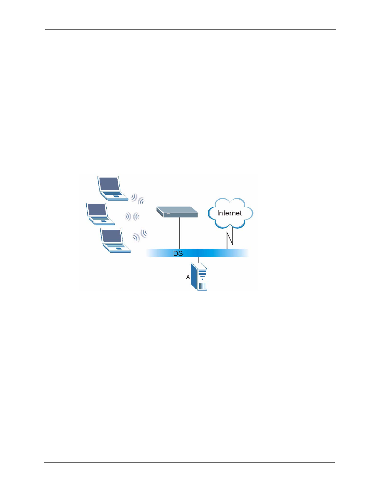
4.4.6 WPA with RADIUS Application Example
You need the IP address of the RADIUS server, its port number (default is 1812), and the
RADIUS shared secret. A WPA application example with an external RADIUS server looks
as follows. "A" is the RADIUS server. "DS" is the distribution system.
1 The AP passes the wireless client's authentication request to the RADIUS server.
2 The RADIUS server then checks the user's identification against its database and grants
or denies network access accordingly.
3 The RADIUS server distributes a Pairwise Master Key (PMK) key to the AP that then
sets up a key hierarchy and management system, using the pair-wise key to dynamically
generate unique data encryption keys to encrypt every data packet that is wirelessly
communicated between the AP and the wireless clients.
Figure 32 WPA with RADIUS Application Example
P-320W User’s Guide
4.4.7 Wireless Client WPA Supplicants
A wireless client supplicant is the software that runs on an operating system instructing the
wireless client how to use WPA. At the time of writing, the most widely available supplicant is
the WPA patch for Windows XP, Funk Software's Odyssey client.
The Windows XP patch is a free download that adds WPA capability to Windows XP's builtin "Zero Configuration" wireless client. However, you must run Windows XP to use it.
4.4.8 WPA Authentication Screen
In order to configure and enable WPA Authentication; click the Wireless LAN link under
Network to display the General screen. Select WPA from the Security Mode list.
Chapter 4 Wireless LAN 69
Page 70
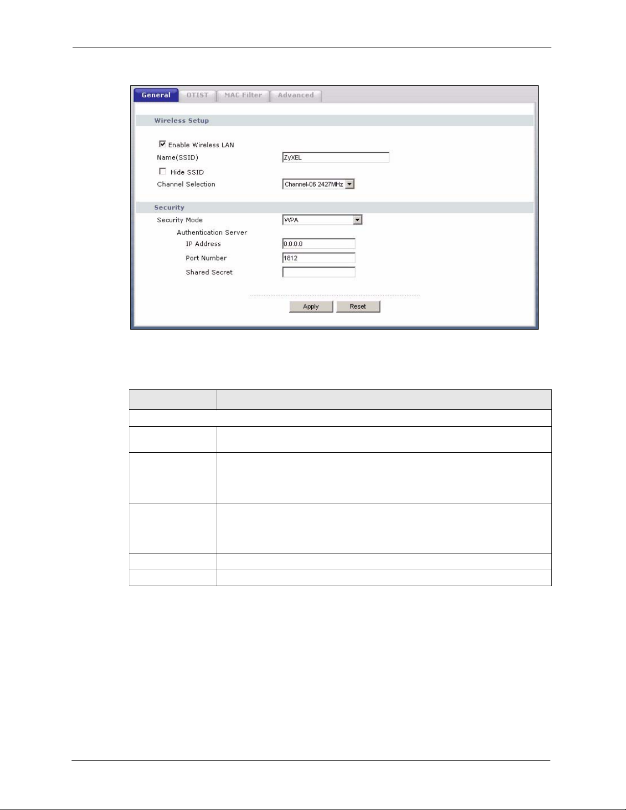
P-320W User’s Guide
Figure 33 Wireless: WPA
The following table describes the labels in this screen.
Table 24 Wireless: WPA
LABEL DESCRIPTION
Authentication Server
IP Address Enter the IP address of the external authentication server in dotted decimal
notation.
Port Number Enter the port number of the external authentication server. The default port
Shared Secret Enter a password (up to 31 alphanumeric characters) as the key to be shared
Apply Click Apply to save your changes back to the Prestige.
Reset Click Reset to reload the previous configuration for this screen.
number is 1812.
You need not change this value unless your network administrator instructs you
to do so with additional information.
between the external authentication server and the Prestige.
The key must be the same on the external authentication server and your
Prestige. The key is not sent over the network.
4.4.9 IEEE 802.1x Overview
You need the following for IEEE 802.1x authentication.
• A computer with an IEEE 802.11 a/b/g wireless LAN adapter and equipped with a web
browser (with JavaScript enabled) and/or Telnet.
70 Chapter 4 Wireless LAN
Page 71
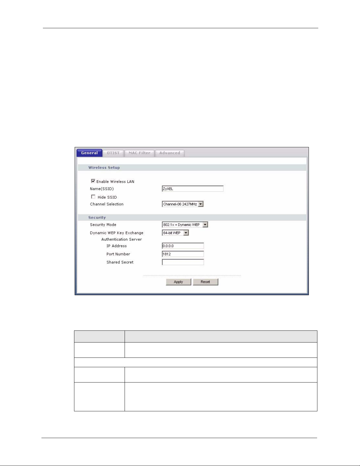
P-320W User’s Guide
• A wireless station computer must be running IEEE 802.1x-compliant software. Not all
Windows operating systems support IEEE 802.1x (see the Microsoft web site for details).
For other operating systems, see their documentation. If your operating system does not
support IEEE 802.1x, then you may need to install IEEE 802.1x client software.
• An optional network RADIUS server for remote user authentication and accounting.
4.4.10 IEEE 802.1x and Dynamic WEP Key Exchange Screen
In order to configure and enable 802.1x and dynamic WEP key exchange; click the Wireless
LAN link under Network to display the General screen. Select 802.1x + Dynamic WEP
from the Security Mode list.
Figure 34 Wireless: 802.1x and Dynamic WEP
The following table describes the labels in this screen.
Table 25 Wireless: 802.1x and Dynamic WEP
LABEL DESCRIPTION
Dynamic WEP Key
Exchange
Authentication Server
IP Address Enter the IP address of the external authentication server in dotted decimal
Port Number Enter the port number of the external authentication server. The default port
Chapter 4 Wireless LAN 71
Select 64-bit WEP or 128-bit WEP to enable data encryption. Up to 32 stations
can access the Prestige when you configure dynamic WEP key exchange.
notation.
number is 1812.
You need not change this value unless your network administrator instructs you
to do so with additional information.
Page 72

P-320W User’s Guide
Table 25 Wireless: 802.1x and Dynamic WEP
LABEL DESCRIPTION
Shared Secret Enter a password (up to 31 alphanumeric characters) as the key to be shared
Apply Click Apply to save your changes back to the Prestige.
Reset Click Reset to reload the previous configuration for this screen.
4.5 OTIST
OTIST (One-Touch Intelligent Security Technology) allows your Prestige to set the wireless
client to use the same wireless settings as the Prestige.
Note: The wireless client must support OTIST and have OTIST enabled.
The following are the wireless settings that the Prestige assigns to the wireless client if OTIST
is enabled on both devices and the OTIST setup keys are the same.
between the external authentication server and the Prestige.
The key must be the same on the external authentication server and your
Prestige. The key is not sent over the network.
•SSID
• Security (WEP or WPA-PSK)
Note: This will replace the pre-configured wireless settings on the wireless clients.
4.5.1 Enabling OTIST
You must enable OTIST on both the AP and wireless client before you start transferring
settings.
Note: The AP and wireless client(s) MUST use the same Setup key.
4.5.1.1 AP
You can enable OTIST using the Reset button or the web configurator.
4.5.1.1.1 Reset button
If you use the Reset button, the default (01234567) or previous saved (through the web
configurator) Setup key is used to encrypt the settings that you want to transfer.
Hold in the Reset button for one or two seconds.
Note: If you hold in the Reset button too long, the device will reset to the factory
defaults!
72 Chapter 4 Wireless LAN
Page 73
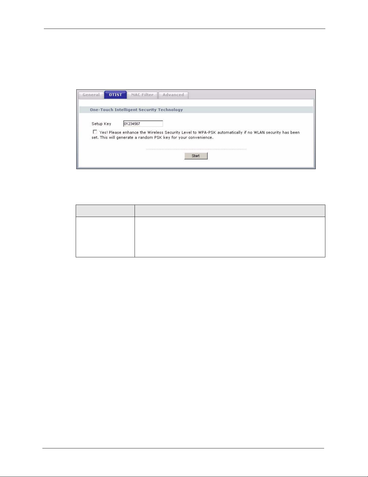
4.5.1.1.2 Web Configurator
Click the Wireless LAN link under Network and then the OTIST tab. The following screen
displays.
Figure 35 Wireless: OTIST
The following table describes the labels in this screen.
Table 26 Wireless: OTIST
P-320W User’s Guide
LABEL DESCRIPTION
Setup Key Type an OTIST Setup Key of exactly eight ASCII characters in length.
The default OTIST setup key is "01234567".
Note: If you change the OTIST setup key here, you must also
make the same change on the wireless client(s).
Chapter 4 Wireless LAN 73
Page 74

P-320W User’s Guide
Table 26 Wireless: OTIST
LABEL DESCRIPTION
Yes! To have OTIST automatically generate a WPA-PSK key, select this check box.
Star t Click Start to encrypt the wireless security data using the setup key and have
If you manually configured a WEP key or a WPA-PSK key and you also select
this check box, then the key you manually configured is used.
If you want to configure your own WPA-PSK and have OTIST use that WPAPSK, you must:
• Configure a WPA-PSK in the Wireless General screen.
• Clear the Ye s! checkbox in the OTIST screen and click Apply.
Note: If you already have a WPA-PSK configured in the
Wireless General screen, and you run OTIST with Yes!
selected, OTIST will not replace the WPA-PSK. Clear the
checkbox in the OTIST screen.
If you want OTIST to automatically generate a WPA-PSK, you must:
• Change your security to No Security in the Wireless General screen.
• Select the the Yes! checkbox in the OTIST screen and click Apply.
• The Wireless General screen displays an auto generated WPA-PSK and
is now in WPA-PSK security mode.
The WPA-PSK security settings are assigned to the wireless client when you
start OTIST.
the Prestige set the wireless station to use the same wireless settings as the
Prestige. You must also activate and start OTIST on the wireless station at the
same time.
The process takes three minutes to complete.
4.5.1.2 Wireless Client
Start the ZyXEL utility and click the Adapter tab. Select the OTIST check box, enter the
same Setup Key as your AP’s and click Save.
Figure 36 Example Wireless Client OTIST Screen
74 Chapter 4 Wireless LAN
Page 75
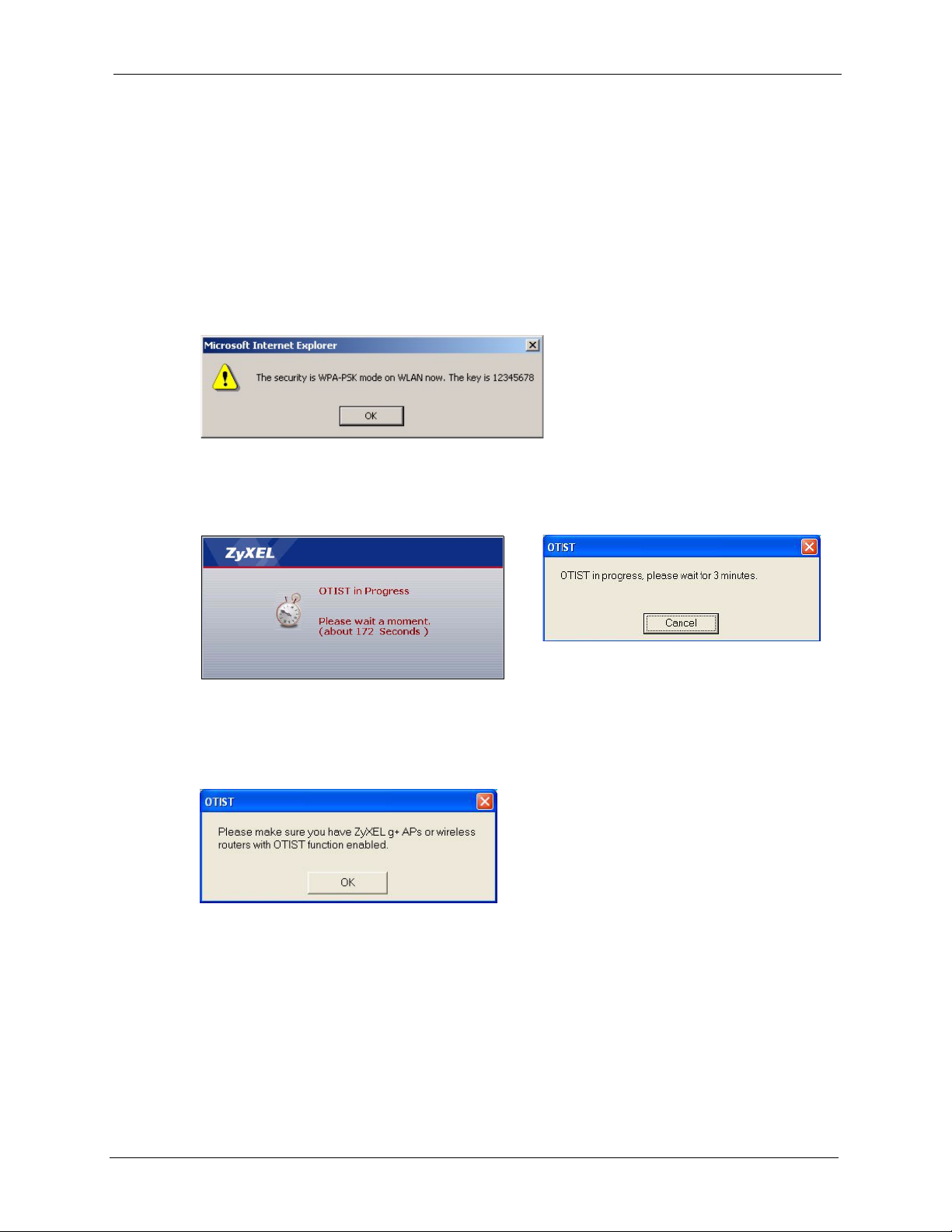
4.5.2 Starting OTIST
Note: You must click Start in the AP OTIST web configurator screen and in the
wireless client(s) Adapter screen all within three minutes (at the time of
writing). You can start OTIST in the wireless clients and AP in any order but
they must all be within range and have OTIST enabled.
1 In the AP, a web configurator screen pops up showing you the security settings to
transfer. After reviewing the settings, click OK.
Figure 37 Security Key
2 This screen appears while OTIST settings are being transferred. It closes when the
transfer is complete.
P-320W User’s Guide
Figure 38 OTIST in Progress (AP) Figure 39 OTIST in Progress (Client)
• In the wireless client, you see this screen if it can't find an OTIST-enabled AP (with the
same Setup key). Click OK to go back to the ZyXEL utility main screen.
Figure 40 No AP with OTIST Found
• If there is more than one OTIST-enabled AP within range, you see a screen asking you to
select one AP to get settings from.
4.5.3 Notes on OTIST
1 If you enabled OTIST in the wireless client, you see this screen each time you start the
utility. Click Ye s for it to search for an OTIST-enabled AP.
Chapter 4 Wireless LAN 75
Page 76

P-320W User’s Guide
Figure 41 Start OTIST?
2 If an OTIST-enabled wireless client loses its wireless connection for more than ten
seconds, it will search for an OTIST-enabled AP for up to one minute. (If you manually
have the wireless client search for an OTIST-enabled AP, there is no timeout; click
Cancel in the OTIST progress screen to stop the search.)
3 When the wireless client finds an OTIST-enabled AP, you must still click Start in the AP
OTIST web configurator screen or hold in the Reset button (for one or two seconds) for
the AP to transfer settings.
4 If you change the SSID or the keys on the AP after using OTIST, you need to run OTIST
again or enter them manually in the wireless client(s).
5 If you configure OTIST to generate a WPA-PSK key, this key changes each time you run
OTIST. Therefore, if a new wireless client joins your wireless network, you need to run
OTIST on the AP and ALL wireless clients again.
4.6 MAC Filter
The MAC filter screen allows you to configure the Prestige to give exclusive access to up to
32 devices (Allow) or exclude up to 32 devices from accessing the Prestige (Deny). Every
Ethernet device has a unique MAC (Media Access Control) address. The MAC address is
assigned at the factory and consists of six pairs of hexadecimal characters, for example, 00A0-C5-00-00-02. You need to know the MAC address of the devices to configure this screen.
To change your Prestige’s MAC filter settings, click the Wireless LAN link under Network
and then the MAC Filter tab. The screen appears as shown.
76 Chapter 4 Wireless LAN
Page 77

Figure 42 Wireless: MAC Address Filter
P-320W User’s Guide
The following table describes the labels in this menu.
Table 27 MAC Address Filter
LABEL DESCRIPTION
Active Select Yes from the drop down list box to enable MAC address filtering.
Filter Action
Set
MAC Address
Apply Click Apply to save your changes back to the Prestige.
Reset Click Reset to reload the previous configuration for this screen.
Chapter 4 Wireless LAN 77
Define the filter action for the list of MAC addresses in the MAC Address table.
Select Deny to block access to the Prestige, MAC addresses not listed will be allowed
to access the Prestige
Select Allow to permit access to the Prestige, MAC addresses not listed will be denied
access to the Prestige.
This is the index number of the MAC address.
Enter the MAC addresses of the wireless station that are allowed or denied access to
the Prestige in these address fields. Enter the MAC addresses in a valid MAC address
format, that is, six hexadecimal character pairs, for example, 12:34:56:78:9a:bc.
Page 78

P-320W User’s Guide
4.7 Wireless LAN Advanced Screen
See the appendix for background information on roaming.
To enable roaming on your Prestige, click the Wireless LAN link under Network and then the
Advanced tab. The screen appears as shown.
Figure 43 Wireless: Advanced
The following table describes the labels in this screen.
Table 28 Wireless: Advanced
LABEL DESCRIPTION
Wireless Advanced Setup
RTS/CTS
Threshold
Fragmentation
Threshold
Preamble Preamble is used to signal that data is coming to the receiver.
Enter a value between 0 and 2432.
It is the maximum data fragment size that can be sent. Enter a value between 256 and
2432.
Short preamble increases performance as less time sending preamble means more
time for sending data. All IEEE 802.11b compliant wireless adapters support long
preamble, but not all support short preamble.
Select Long preamble if you are unsure what preamble mode the wireless adapters
support, and to provide more reliable communications in busy wireless networks.
Select Short preamble if you are sure the wireless adapters support it, and to provide
more efficient communications.
Note: The Prestige and the wireless stations MUST use the same
preamble mode in order to communicate.
802.11 Mode Select 802.11b Only to allow only IEEE 802.11b compliant WLAN devices to
associate with the Prestige.
Select 802.11g Only to allow only IEEE 802.11g compliant WLAN devices to
associate with the Prestige.
Select Mixed to allow either IEEE802.11b or IEEE802.11g compliant WLAN devices
to associate with the Prestige. The transmission rate of your Prestige might be
reduced.
78 Chapter 4 Wireless LAN
Page 79

Table 28 Wireless: Advanced
LABEL DESCRIPTION
Apply Click Apply to save your changes back to the Prestige.
Reset Click Reset to reload the previous configuration for this screen.
P-320W User’s Guide
Chapter 4 Wireless LAN 79
Page 80

P-320W User’s Guide
80 Chapter 4 Wireless LAN
Page 81

This chapter describes how to configure WAN settings.
5.1 WAN IP Address Assignment
Every computer on the Internet must have a unique IP address. If your networks are isolated
from the Internet, for instance, only between your two branch offices, you can assign any IP
addresses to the hosts without problems. However, the Internet Assigned Numbers Authority
(IANA) has reserved the following three blocks of IP addresses specifically for private
networks.
Table 29 Private IP Address Ranges
P-320W User’s Guide
CHAPTER 5
WAN
10.0.0.0 - 10.255.255.255
172.16.0.0 - 172.31.255.255
192.168.0.0 - 192.168.255.255
You can obtain your IP address from the IANA, from an ISP or have it assigned by a private
network. If you belong to a small organization and your Internet access is through an ISP, the
ISP can provide you with the Internet addresses for your local networks. On the other hand, if
you are part of a much larger organization, you should consult your network administrator for
the appropriate IP addresses.
Note: Regardless of your particular situation, do not create an arbitrary IP address;
always follow the guidelines above. For more information on address
assignment, please refer to RFC 1597, Address Allocation for Private Internets
and RFC 1466, Guidelines for Management of IP Address Space.
5.2 IP Address and Subnet Mask
Similar to the way houses on a street share a common street name, so too do computers on a
LAN share one common network number.
Where you obtain your network number depends on your particular situation. If the ISP or
your network administrator assigns you a block of registered IP addresses, follow their
instructions in selecting the IP addresses and the subnet mask.
Chapter 5 WAN 81
Page 82

P-320W User’s Guide
If the ISP did not explicitly give you an IP network number, then most likely you have a single
user account and the ISP will assign you a dynamic IP address when the connection is
established. The Internet Assigned Number Authority (IANA) reserved this block of addresses
specifically for private use; please do not use any other number unless you are told otherwise.
Let's say you select 192.168.1.0 as the network number; which covers 254 individual
addresses, from 192.168.1.1 to 192.168.1.254 (zero and 255 are reserved). In other words, the
first three numbers specify the network number while the last number identifies an individual
computer on that network.
Once you have decided on the network number, pick an IP address that is easy to remember,
for instance, 192.168.1.1, for your Prestige, but make sure that no other device on your
network is using that IP address.
The subnet mask specifies the network number portion of an IP address. Your Prestige will
compute the subnet mask automatically based on the IP address that you entered. You don't
need to change the subnet mask computed by the Prestige unless you are instructed to do
otherwise.
5.3 DNS Server Address Assignment
Use DNS (Domain Name System) to map a domain name to its corresponding IP address and
vice versa, for instance, the IP address of www.zyxel.com is 204.217.0.2. The DNS server is
extremely important because without it, you must know the IP address of a computer before
you can access it.
The Prestige can get the DNS server addresses in the following way.
1 The ISP tells you the DNS server addresses, usually in the form of an information sheet,
when you sign up. If your ISP gives you DNS server addresses, enter them in the DNS
Server fields in DHCP Setup.
If the ISP did not give you DNS server information, leave the DNS Server fields in DHCP
Setup set to 0.0.0.0 for the ISP to dynamically assign the DNS server IP addresses.
5.4 TCP/IP Priority (Metric)
The metric represents the "cost of transmission". A router determines the best route for
transmission by choosing a path with the lowest "cost". RIP routing uses hop count as the
measurement of cost, with a minimum of "1" for directly connected networks. The number
must be between "1" and "15"; a number greater than "15" means the link is down. The
smaller the number, the lower the "cost".
The metric sets the priority for the Prestige’s routes to the Internet. If the routes have the same
metric, the Prestige uses the following pre-defined priorities:
1 WA N: designated by the ISP or a static route (see Chapter 10 on page 115)
82 Chapter 5 WAN
Page 83

2 Traffic Redirect (see Section 5.9 on page 90)
For example, if WA N has a metric of "1" and Traffic Redirect has a metric of "2", the WAN
connection acts as the primary default route. If the WA N route fails to connect to the Internet,
the Prestige tries Traffic Redirect next.
5.5 WAN MAC Address
Every Ethernet device has a unique MAC (Media Access Control) address. The MAC address
is assigned at the factory and consists of six pairs of hexadecimal characters, for example, 00A0-C5-00-00-02.
You can configure the WAN port's MAC address by either using the factory default or cloning
the MAC address from a computer on your LAN. Once it is successfully configured, the
address will be copied to the "rom" file (ZyNOS configuration file). It will not change unless
you change the setting or upload a different "rom" file.
Table 30 Example of Network Properties for LAN Servers with Fixed IP Addresses
P-320W User’s Guide
Choose an IP address 192.168.1.2-192.168.1.32; 192.168.1.65-192.168.1.254.
Subnet mask 255.255.255.0
Gateway (or default route) 192.168.1.1(Prestige LAN IP)
5.6 Internet Connection
To change your Prestige’s WAN ISP, IP and MAC settings, click WA N under Network. The
screen differs by the encapsulation.
5.6.1 Ethernet Encapsulation
The screen shown next is for Ethernet encapsulation.
Chapter 5 WAN 83
Page 84
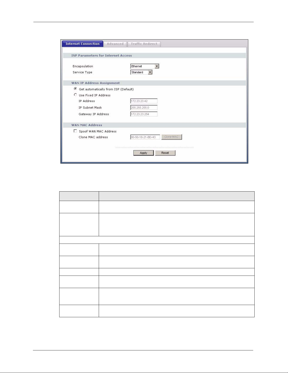
P-320W User’s Guide
Figure 44 WAN: Ethernet Encapsulation
The following table describes the labels in this screen.
Table 31 WAN: Ethernet Encapsulation
LABEL DESCRIPTION
Encapsulation You must choose the Ethernet option when the WAN port is used as a regular
Ethernet.
Service Type Choose from Standard, Tel stra (RoadRunner Telstra authentication method),
WAN IP Address Assignment
Get automatically
from ISP
Use fixed IP
address
IP Address Enter your WAN IP address in this field if you selected Use Fixed IP Address.
Remote IP
Subnet Mask
Backup
Gateway IP
Address
WAN MAC
Address
RR-Manager (Roadrunner Manager authentication method), RR-Toshiba
(Roadrunner Toshiba authentication method) or Telia Login.
The following fields do not appear with the Standard service type.
Select this option If your ISP did not assign you a fixed IP address. This is the
default selection.
Select this option If the ISP assigned a fixed IP address.
Enter the Remote IP Subnet Mask (if your ISP gave you one) in this field.
Enter a Backup Gateway IP Address (if your ISP gave you one) in this field.
84 Chapter 5 WAN
Page 85

Table 31 WAN: Ethernet Encapsulation
LABEL DESCRIPTION
P-320W User’s Guide
Spoof WAN MAC
Address
Clone MAC
address
Apply Click Apply to save your changes back to the Prestige.
Reset Click Reset to begin configuring this screen afresh.
The MAC address section allows users to configure the WAN port's MAC address
by either using the factory default or cloning the MAC address from a computer on
your LAN.
Clear the check box to use the factory assigned default MAC Address.
Select this option and and click Clone MAC to clone the MAC address in the MAC
Address field.
Enter the MAC address of the computer on the LAN whose MAC you are cloning.
Once it is successfully configured, the address will be copied to the rom file
(ZyNOS configuration file). It will not change unless you change the setting or
upload a different ROM file.
5.6.2 PPPoE Encapsulation
The Prestige supports PPPoE (Point-to-Point Protocol over Ethernet). PPPoE is an IETF
standard (RFC 2516) specifying how a personal computer (PC) interacts with a broadband
modem (DSL, cable, wireless, etc.) connection. The PPP over Ethernet option is for a dialup connection using PPPoE.
For the service provider, PPPoE offers an access and authentication method that works with
existing access control systems (for example RADIUS).
One of the benefits of PPPoE is the ability to let you access one of multiple network services,
a function known as dynamic service selection. This enables the service provider to easily
create and offer new IP services for individuals.
Operationally, PPPoE saves significant effort for both you and the ISP or carrier, as it requires
no specific configuration of the broadband modem at the customer site.
By implementing PPPoE directly on the Prestige (rather than individual computers), the
computers on the LAN do not need PPPoE software installed, since the Prestige does that part
of the task. Furthermore, with NAT, all of the LANs’ computers will have access.
The screen shown next is for PPPoE encapsulation.
Chapter 5 WAN 85
Page 86
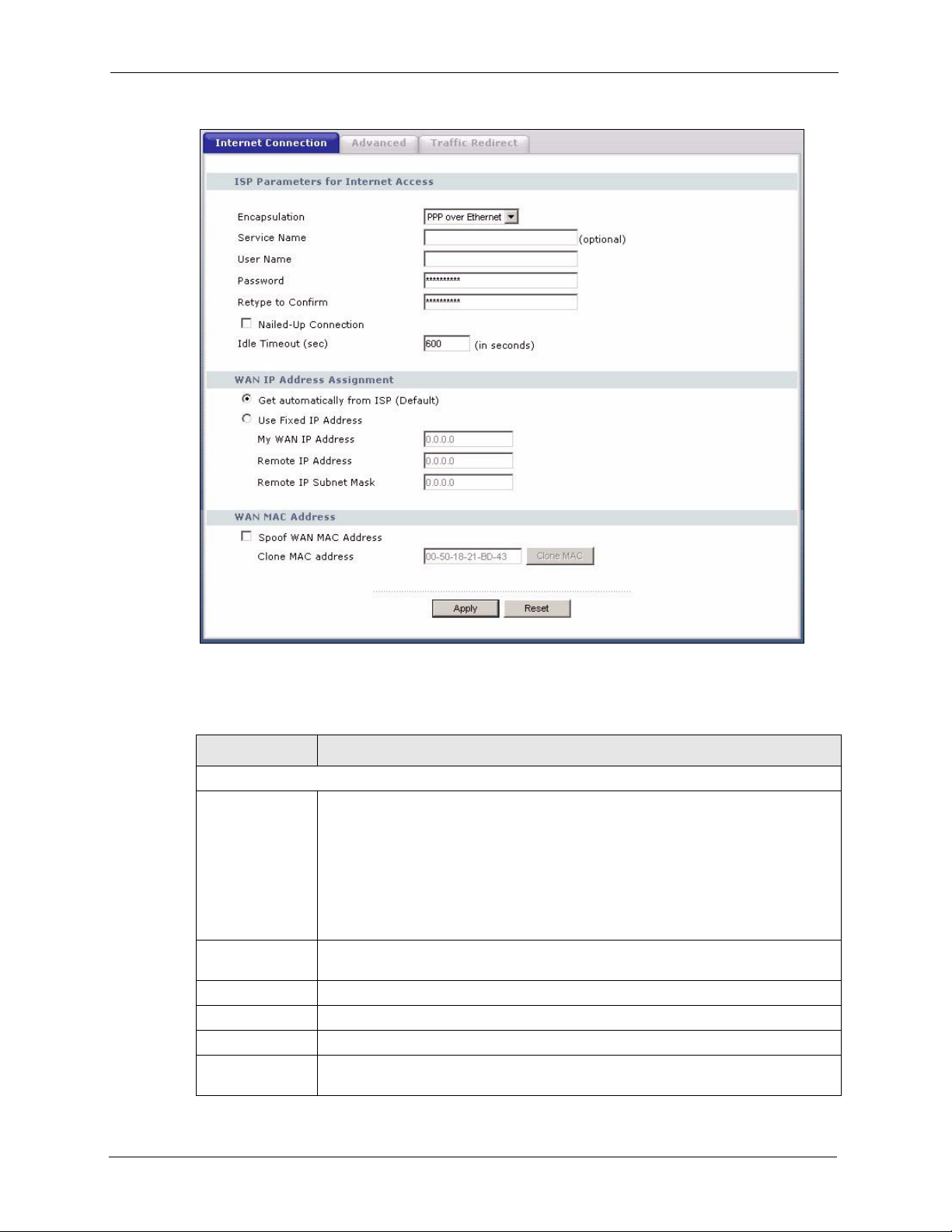
P-320W User’s Guide
Figure 45 WAN: PPPoE Encapsulation
The following table describes the labels in this screen.
Table 32 WAN: PPPoE Encapsulation
LABEL DESCRIPTION
ISP Parameters for Internet Access
Encapsulation The PPP over Ethernet choice is for a dial-up connection using PPPoE. The
Prestige supports PPPoE (Point-to-Point Protocol over Ethernet). PPPoE is an
IETF standard (RFC 2516) specifying how a personal computer (PC) interacts with
a broadband modem (i.e. xDSL, cable, wireless, etc.) connection. Operationally,
PPPoE saves significant effort for both the end user and ISP/carrier, as it requires
no specific configuration of the broadband modem at the customer site. By
implementing PPPoE directly on the router rather than individual computers, the
computers on the LAN do not need PPPoE software installed, since the router does
that part of the task. Further, with NAT, all of the LAN's computers will have access.
Service Name Type the PPPoE service name provided to you. PPPoE uses a service name to
identify and reach the PPPoE server.
User Name Type the User Name given to you by your ISP.
Password Type the password associated with the User Name above.
Retype to Confirm Type your password again to make sure that you have entered is correctly.
Nailed-Up
Connection
Select Nailed-Up Connection if you do not want the connection to time out.
86 Chapter 5 WAN
Page 87

P-320W User’s Guide
Table 32 WAN: PPPoE Encapsulation
LABEL DESCRIPTION
Idle Timeout This value specifies the time in seconds that elapses before the router automatically
disconnects from the PPPoE server.
WAN IP Address Assignment
Get automatically
from ISP
Use fixed IP
address
My WAN IP
Address
Remote IP
Address
Remote IP
Subnet Mask
WAN MAC
Address
Spoof WAN MAC
Address
Clone MAC
address
Apply Click Apply to save your changes back to the Prestige.
Reset Click Reset to begin configuring this screen afresh.
Select this option If your ISP did not assign you a fixed IP address. This is the
default selection.
Select this option If the ISP assigned a fixed IP address.
Enter your WAN IP address in this field if you selected Use Fixed IP Address.
Enter the Remote IP Address (if your ISP gave you one) in this field.
Enter the Rmote IP subnet Mask in this field.
The MAC address section allows users to configure the WAN port's MAC address
by either using the factory default or cloning the MAC address from a computer on
your LAN.
Clear the check box to use the factory assigned default MAC Address.
Select this option and and click Clone MAC to clone the MAC address in the MAC
Address field.
Enter the MAC address of the computer on the LAN whose MAC you are cloning.
Once it is successfully configured, the address will be copied to the rom file (ZyNOS
configuration file). It will not change unless you change the setting or upload a
different ROM file.
5.6.3 PPTP Encapsulation
Point-to-Point Tunneling Protocol (PPTP) is a network protocol that enables secure transfer of
data from a remote client to a private server, creating a Virtual Private Network (VPN) using
TCP/IP-based networks.
PPTP supports on-demand, multi-protocol and virtual private networking over public
networks, such as the Internet.
The screen shown next is for PPTP encapsulation.
Chapter 5 WAN 87
Page 88
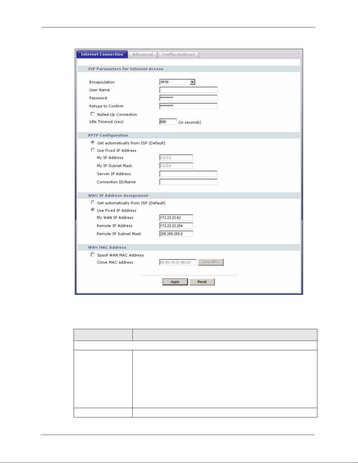
P-320W User’s Guide
Figure 46 PPTP Encapsulation
The following table describes the labels in this screen.
Table 33 PPTP Encapsulation
LABEL DESCRIPTION
ISP Parameters for Internet Access
Encapsulation Point-to-Point Tunneling Protocol (PPTP) is a network protocol that enables
secure transfer of data from a remote client to a private server, creating a
Virtual Private Network (VPN) using TCP/IP-based networks. PPTP supports
on-demand, multi-protocol, and virtual private networking over public
networks, such as the Internet. The Prestige supports only one PPTP server
connection at any given time.
To configure a PPTP client, you must configure the User Name and
Password fields for a PPP connection and the PPTP parameters for a PPTP
connection.
User Name Type the user name given to you by your ISP.
88 Chapter 5 WAN
Page 89

P-320W User’s Guide
Table 33 PPTP Encapsulation
LABEL DESCRIPTION
Password Type the password associated with the User Name above.
Retype to Confirm Type your password again to make sure that you have entered is correctly.
Nailed-up Connection Select Nailed-Up Connection if you do not want the connection to time out.
Idle Timeout This value specifies the time in seconds that elapses before the Prestige
automatically disconnects from the PPTP server.
PPTP Configuration
Get automatically from
ISP
Use fixed IP address Select this option If the ISP assigned a fixed IP address.
My IP Address Type the (static) IP address assigned to you by your ISP.
My IP Subnet Mask Your Prestige will automatically calculate the subnet mask based on the IP
Server IP Address Type the IP address of the PPTP server.
Connection ID/
Name
WAN IP Address Assignment
Get automatically from
ISP
Use fixed IP address Select this option If the ISP assigned a fixed IP address.
My WAN IP
Address
Remote IP Address Enter the Remote IP Address (if your ISP gave you one) in this field.
Remote IP Subnet
Mask
WAN MAC Address
Spoof WAN MAC
Address
Clone MAC address Enter the MAC address of the computer on the LAN whose MAC you are
Apply Click Apply to save your changes back to the Prestige.
Reset Click Reset to begin configuring this screen afresh.
Select this option If your ISP did not assign you a fixed IP address. This is the
default selection.
address that you assign. Unless you are implementing subnetting, use the
subnet mask computed by the Prestige.
Type your identification name for the PPTP server.
Select this option If your ISP did not assign you a fixed IP address. This is the
default selection.
Enter your WAN IP address in this field if you selected Use Fixed IP Address.
Enter the Rmote IP subnet Mask in this field.
The MAC address section allows users to configure the WAN port's MAC
address by either using the factory default or cloning the MAC address from a
computer on your LAN.
Clear the check box to use the factory assigned default MAC Address.
Select this option and and click Clone MAC to clone the MAC address in the
MAC Address field.
cloning. Once it is successfully configured, the address will be copied to the
rom file (ZyNOS configuration file). It will not change unless you change the
setting or upload a different ROM file.
5.7 Advanced WAN Screen
To change your Prestige’s advanced WAN settings, click the WAN link under Network, and
the Advanced tab. The screen appears as shown.
Chapter 5 WAN 89
Page 90

P-320W User’s Guide
Figure 47 Advanced
The following table describes the labels in this screen.
Table 34 Advanced
LABEL DESCRIPTION
DNS Servers
First DNS Server
Second DNS Server
Apply Click Apply to save your changes back to the Prestige.
Reset Click Reset to begin configuring this screen afresh.
Enter the IP address(es) of the DNS server(s). If you do not configure a DNS
server, you must know the IP address of a computer in order to access it.
5.8 Traffic Redirect
Traffic redirect forwards WAN traffic to a backup gateway when the Prestige cannot connect
to the Internet through its normal gateway. Connect the backup gateway on the WAN so that
the Prestige still provides firewall protection.
Figure 48 Traffic Redirect WAN Setup
5.9 Traffic Redirect Screen
To change your Prestige’s Traffic Redirect settings, click the WAN link under Network and
the Traffic Redirect tab. The screen appears as shown.
90 Chapter 5 WAN
Page 91
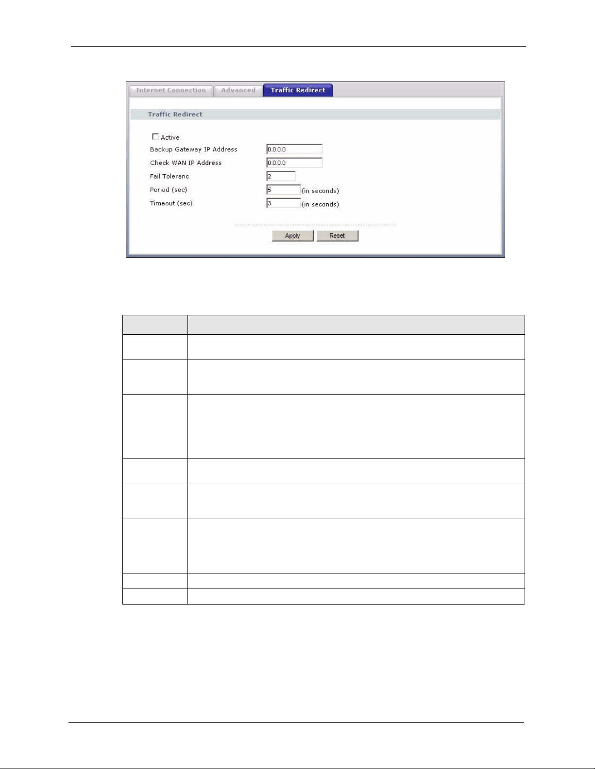
Figure 49 WAN: Traffic Redirect
The following table describes the labels in this screen.
Table 35 Traffic Redirect
P-320W User’s Guide
LABEL DESCRIPTION
Active Select this check box to have the Prestige use traffic redirect if the normal WAN
connection goes down.
Backup
Gateway IP
Address
Check WAN IP
Address
Fail Tolerance Type the number of times your Prestige may attempt and fail to connect to the Internet
Period
(seconds)
Timeout
(seconds)
Apply Click Apply to save your changes back to the Prestige.
Reset Click Reset to begin configuring this screen afresh.
Type the IP address of your backup gateway in dotted decimal notation. The Prestige
automatically forwards traffic to this IP address if the Prestige's Internet connection
terminates.
Configuration of this field is optional. If you do not enter an IP address here, the
Prestige will use the default gateway IP address. Configure this field to test your
Prestige's WAN accessibility. Type the IP address of a reliable nearby computer (for
example, your ISP's DNS server address). If you are using PPTP or PPPoE
Encapsulation, type "0.0.0.0" to configure the Prestige to check the PVC (Permanent
Virtual Circuit) or PPTP tunnel.
before traffic is forwarded to the backup gateway.
Type the number of seconds for the Prestige to wait between checks to see if it can
connect to the WAN IP address (Check WAN IP Address field) or default gateway.
Allow more time if your destination IP address handles lots of traffic.
Type the number of seconds for your Prestige to wait for a ping response from the IP
Address in the Check WAN IP Address field before it times out. The WAN connection
is considered "down" after the Prestige times out the number of times specified in the
Fail Tolerance field. Use a higher value in this field if your network is busy or
congested.
Chapter 5 WAN 91
Page 92

P-320W User’s Guide
92 Chapter 5 WAN
Page 93

This chapter describes how to configure LAN settings.
6.1 LAN Overview
Local Area Network (LAN) is a shared communication system to which many computers are
attached. The LAN screens can help you configure a LAN DHCP server, manage IP addresses,
and partition your physical network into logical networks.
6.1.1 IP Pool Setup
The Prestige is pre-configured with a pool of 32 IP addresses starting from 192.168.1.33 to
192.168.1.64. This configuration leaves 31 IP addresses (excluding the Prestige itself) in the
lower range for other server computers, for instance, servers for mail, FTP, TFTP, web, etc.,
that you may have.
P-320W User’s Guide
CHAPTER 6
LAN
6.1.2 System DNS Servers
Refer to the IP Address and Subnet Mask section in the Wizard Connection chapter.
6.2 LAN TCP/IP
The Prestige has built-in DHCP server capability that assigns IP addresses and DNS servers to
systems that support DHCP client capability.
6.2.1 Factory LAN Defaults
The LAN parameters of the Prestige are preset in the factory with the following values:
• IP address of 192.168.1.1 with subnet mask of 255.255.255.0 (24 bits)
• DHCP server enabled with 32 client IP addresses starting from 192.168.1.33.
These parameters should work for the majority of installations. If your ISP gives you explicit
DNS server address(es), read the embedded web configurator help regarding what fields need
to be configured.
Chapter 6 LAN 93
Page 94
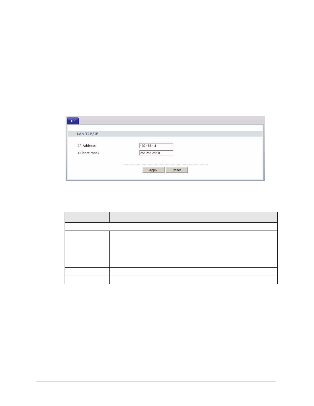
P-320W User’s Guide
6.2.2 IP Address and Subnet Mask
Refer to the section about IP address and subnet mask in the Wizard Setup chapter for this
information.
6.3 IP Screen
Click the LAN link under Network to open the IP screen.
Figure 50 LAN IP
The following table describes the labels in this screen.
Table 36 LAN IP
LABEL DESCRIPTION
LAN TCP/IP
IP Address Type the IP address of your Prestige in dotted decimal notation 192.168.1.1
(factory default).
IP Subnet Mask The subnet mask specifies the network number portion of an IP address. Your
Prestige will automatically calculate the subnet mask based on the IP address
that you assign. Unless you are implementing subnetting, use the subnet mask
computed by the Prestige 255.255.255.0.
Apply Click Apply to save your changes back to the Prestige.
Reset Click Reset to begin configuring this screen afresh.
94 Chapter 6 LAN
Page 95

7.1 DHCP
DHCP (Dynamic Host Configuration Protocol, RFC 2131 and RFC 2132) allows individual
clients to obtain TCP/IP configuration at start-up from a server. You can configure the Prestige
as a DHCP server or disable it. When configured as a server, the Prestige provides the TCP/IP
configuration for the clients. If DHCP service is disabled, you must have another DHCP server
on your LAN, or else the computer must be manually configured.
7.2 DHCP Screen
P-320W User’s Guide
CHAPTER 7
DHCP Server
Click the DHCP Server link under Network and the General tab. The following screen
displays.
Figure 51 General
Chapter 7 DHCP Server 95
Page 96

P-320W User’s Guide
The following table describes the labels in this screen.
Table 37 General
LABEL DESCRIPTION
Enable DHCP Server DHCP (Dynamic Host Configuration Protocol, RFC 2131 and RFC 2132)
IP Pool Starting
Address
Pool Size This field specifies the size, or count of the IP address pool.
DNS Servers Assigned by DHCP Server
The Prestige passes a DNS (Domain Name System) server IP address (in the order you specify here)
to the DHCP clients. The Prestige only passes this information to the LAN DHCP clients when you
select the Enable DHCP Server check box. When you clear the Enable DHCP Server check box,
DHCP service is disabled and you must have another DHCP sever on your LAN, or else the computers
must have their DNS server addresses manually configured.
First DNS Server
Second DNS Server
Apply Click Apply to save your changes back to the Prestige.
Reset Click Reset to begin configuring this screen afresh.
allows individual clients (computers) to obtain TCP/IP configuration at startup
from a server. Leave the Enable DHCP Server check box selected unless
your ISP instructs you to do otherwise. Clear it to disable the Prestige acting
as a DHCP server. When configured as a server, the Prestige provides TCP/IP
configuration for the clients. If not, DHCP service is disabled and you must
have another DHCP server on your LAN, or else the computers must be
manually configured. When set as a server, fill in the following four fields.
This field specifies the first of the contiguous addresses in the IP address pool.
Enter the IP address(es) of the DNS server(s). If you do not configure a DNS
server, you must know the IP address of a computer in order to access it.
7.3 Static DHCP Screen
This table allows you to assign IP addresses on the LAN to specific individual computers
based on their MAC addresses.
Every Ethernet device has a unique MAC (Media Access Control) address. The MAC address
is assigned at the factory and consists of six pairs of hexadecimal characters, for example, 00A0-C5-00-00-02.
To change your Prestige’s Static DHCP settings, click the DHCP Server link under Network
and the Static DHCP tab. The following screen displays.
96 Chapter 7 DHCP Server
Page 97
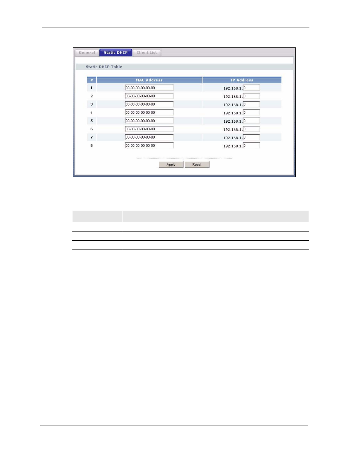
Figure 52 Static DHCP
P-320W User’s Guide
The following table describes the labels in this screen.
Table 38 Static DHCP
LABEL DESCRIPTION
# This is the index number of the Static IP table entry (row).
MAC Address Type the MAC address (with colons) of a computer on your LAN.
IP Address Type the LAN IP address of a computer on your LAN.
Apply Click Apply to save your changes back to the Prestige.
Reset Click Reset to begin configuring this screen afresh.
7.4 Client List Screen
The DHCP table shows current DHCP client information (including IP Address, Host Name
and MAC Address) of all network clients using the Prestige’s DHCP server.
Configure this screen to always assign an IP address to a MAC address (and host name). Click
the DHCP Server link under Network and the Client List tab.
Note: You can also view a read-only client list by clicking the DHCP Table (Detail)
hyperlink in the Status screen.
The following screen displays.
Chapter 7 DHCP Server 97
Page 98
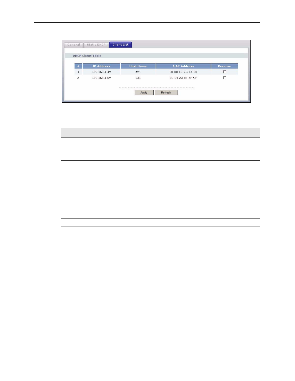
P-320W User’s Guide
Figure 53 Client List
The following table describes the labels in this screen.
Table 39 Client List
LABEL DESCRIPTION
# This is the index number of the host computer.
IP Address This field displays the IP address relative to the # field listed above.
Host Name This field displays the computer host name.
MAC Address The MAC (Media Access Control) or Ethernet address on a LAN (Local Area
Reserve Select this check box to have the Prestige always assign this IP address to this
Apply Click Apply to save your changes back to the Prestige.
Refresh Click Refresh to reload the DHCP table.
Network) is unique to your computer (six pairs of hexadecimal notation).
A network interface card such as an Ethernet adapter has a hardwired address
that is assigned at the factory. This address follows an industry standard that
ensures no other adapter has a similar address.
MAC address (and host name). You can select up to 8 entries in this table.
After you click Apply, the MAC address and IP address also display in the
Static DHCP screen (where you can edit them).
98 Chapter 7 DHCP Server
Page 99

Network Address Translation
This chapter discusses how to configure NAT on the Prestige.
8.1 NAT Overview
NAT (Network Address Translation - NAT, RFC 1631) is the translation of the IP address of a
host in a packet. For example, the source address of an outgoing packet, used within one
network is changed to a different IP address known within another network.
P-320W User’s Guide
CHAPTER 8
(NAT)
8.1.1 NAT Definitions
Inside/outside denotes where a host is located relative to the Prestige. For example, the
computers of your subscribers are the inside hosts, while the web servers on the Internet are
the outside hosts.
Global/local denotes the IP address of a host in a packet as the packet traverses a router. For
example, the local address refers to the IP address of a host when the packet is in the local
network, while the global address refers to the IP address of the host when the same packet is
traveling in the WAN side.
Note that inside/outside refers to the location of a host, while global/local refers to the IP
address of a host used in a packet. Thus, an inside local address (ILA) is the IP address of an
inside host in a packet when the packet is still in the local network, while an inside global
address (IGA) is the IP address of the same inside host when the packet is on the WAN side.
The following table summarizes this information.
Chapter 8 Network Address Translation (NAT) 99
Page 100

P-320W User’s Guide
Table 40 NAT Definitions
TERM DESCRIPTION
Inside This refers to the host on the LAN.
Outside This refers to the host on the WAN.
Local This refers to the packet address (source or destination) as the packet travels on the LAN.
Global This refers to the packet address (source or destination) as the packet travels on the
WAN.
Note: NAT never changes the IP address (either local or global) of an outside host.
8.1.2 What NAT Does
In the simplest form, NAT changes the source IP address in a packet received from a
subscriber (the inside local address) to another (the inside global address) before forwarding
the packet to the WAN side. When the response comes back, NAT translates the destination
address (the inside global address) back to the inside local address before forwarding it to the
original inside host. Note that the IP address (either local or global) of an outside host is never
changed.
The global IP addresses for the inside hosts can be either static or dynamically assigned by the
ISP. In addition, you can designate servers (for example a web server and a telnet server) on
your local network and make them accessible to the outside world. If you do not define any
servers (for Many-to-One and Many-to-Many Overload mapping), NAT offers the additional
benefit of firewall protection. With no servers defined, your Prestige filters out all incoming
inquiries, thus preventing intruders from probing your network. For more information on IP
address translation, refer to RFC 1631, The IP Network Address Translator (NAT).
8.1.3 How NAT Works
Each packet has two addresses – a source address and a destination address. For outgoing
packets, the ILA (Inside Local Address) is the source address on the LAN, and the IGA (Inside
Global Address) is the source address on the WAN. For incoming packets, the ILA is the
destination address on the LAN, and the IGA is the destination address on the WAN. NAT
maps private (local) IP addresses to globally unique ones required for communication with
hosts on other networks. It replaces the original IP source address (and TCP or UDP source
port numbers for Many-to-One and Many-to-Many Overload NAT mapping) in each packet
and then forwards it to the Internet. The Prestige keeps track of the original addresses and port
numbers so incoming reply packets can have their original values restored. The following
figure illustrates this.
100 Chapter 8 Network Address Translation (NAT)
 Loading...