

Page 1
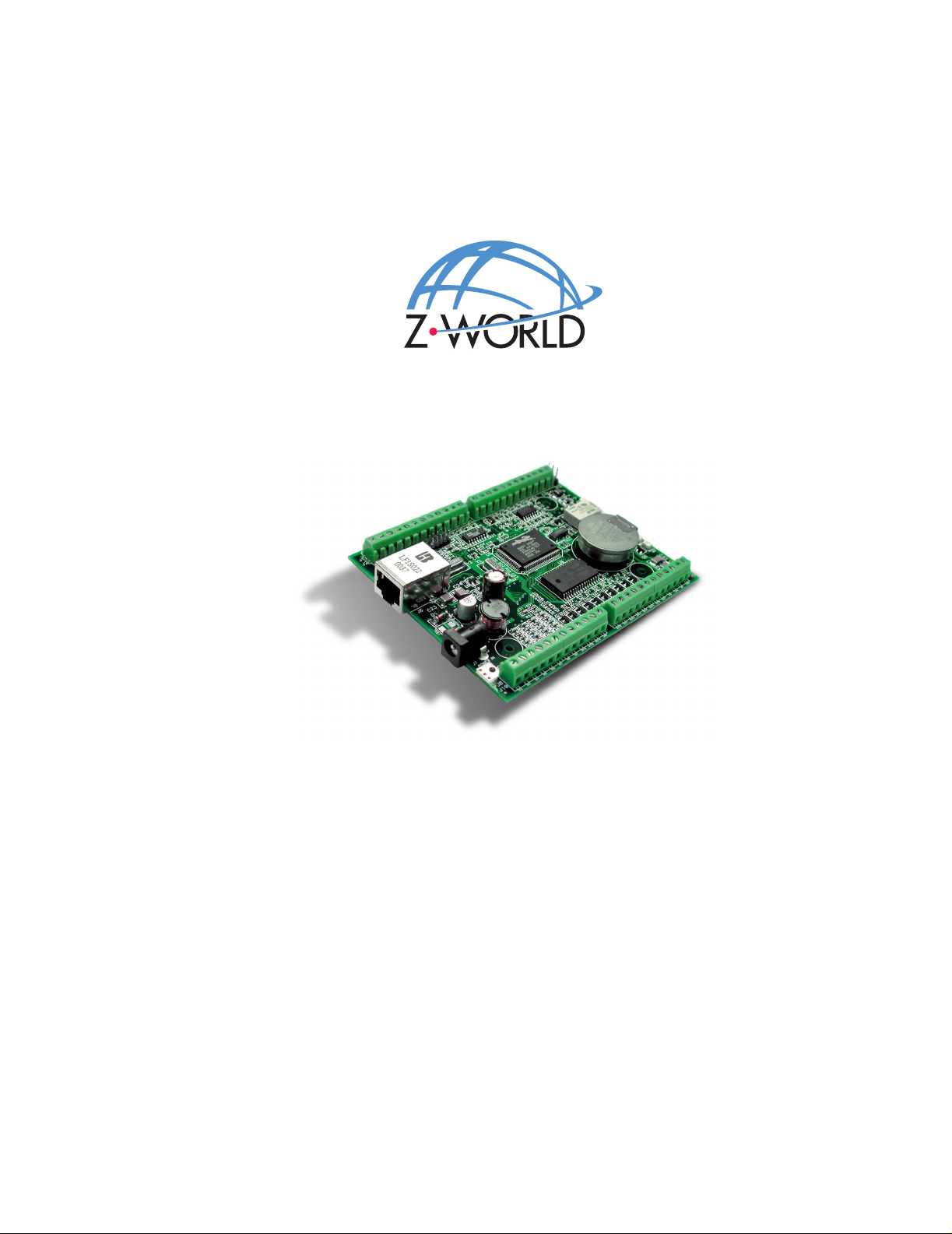
Wildcat (BL2000)
C-Programmable Singl e-Boar d Comp ut er with Et hern et
User’s Manual
019–0094 • 040731–K
Page 2

Wildcat (BL2000) User’s Manual
Part Number 019-0094 • 040731–K • Printed in U. S.A.
©2001–2004 Z-World Inc. • All rights reserved.
Z-World reserves the right to make changes and
improvements to its products without providing n otice.
T r ade mark s
Rabbit and Rabbit 2000 are registered trademarks of Rabbit Semico nductor.
Dynamic C is a registered trademark of Z-World Inc.
Z-World, Inc.
2900 Spafford Street
Davis, California 95616-6800
USA
Tel e phone: (530) 757-3737
Fax: (530) 753-5141
www .zworld.com
Wildcat (BL2000)
Page 3

TABLE OF CONTENTS
Chapter 1. Introduction 1
1.1 BL2000 Description..............................................................................................................................1
1.2 BL2000 Features...................................................................................................................................1
1.2.1 Connector Options........................................................................................................................2
1.3 Development and Evaluation Tools......................................................................................................3
1.3.1 Tool Kit.........................................................................................................................................3
1.3.2 Software........................................................................................................................................4
1.4 CE Compliance.....................................................................................................................................5
1.4.1 Design Guidelines.........................................................................................................................6
1.4.2 Interfacing the BL2000 to Other Devices.....................................................................................6
Chapter 2. Getting Started 7
2.1 BL2000 Connections............................................................................................................................7
2.2 Installing Dynamic C............................................................................................................................9
2.3 Starting Dynamic C ............................................................................................................................10
2.4 PONG.C..............................................................................................................................................11
2.5 Where Do I Go From Here? ...............................................................................................................11
Chapter 3. Subsystems 13
3.1 BL2000 Pinouts..................................................................................................................................14
3.1.1 Headers and Screw Terminals.....................................................................................................15
3.1.2 Power Supply Pins......................................................................................................................15
3.2 Digital I/O...........................................................................................................................................16
3.2.1 Digital Inputs...............................................................................................................................16
3.2.2 Digital Outputs............................................................................................................................18
3.3 Relay Outputs .....................................................................................................................................20
3.4 Serial Communication ........................................................................................................................21
3.4.1 RS-232 ........................................................................................................................................21
3.4.2 RS-485 ........................................................................................................................................21
3.4.3 Programming Port.......................................................................................................................23
3.4.4 Ethernet Port ...............................................................................................................................24
3.5 A/D Converter Inputs..........................................................................................................................26
3.6 D/A Converter Outputs .......................................................................................................................27
3.7 Memory...............................................................................................................................................29
3.7.1 SRAM .........................................................................................................................................29
3.7.2 Flash Memory.............................................................................................................................29
3.8 Programming Cable............................................................................................................................30
3.8.1 Detailed Instructions: Changing from Program Mode to Run Mode..........................................30
3.8.2 Detailed Instructions: Changing from Run Mode to Program Mode..........................................30
3.9 Other Hardware...................................................................................................................................31
3.9.1 External Interrupts.......................................................................................................................31
3.9.2 Clock Doubler.............................................................................................................................31
3.9.3 Spectrum Spreader......................................................................................................................31
Chapter 4. Software 33
4.1 Running Dynamic C...........................................................................................................................33
4.1.1 Upgrading Dynamic C................................................................................................................34
User’s Manual
Page 4

4.2 Sample Programs................................................................................................................................ 35
4.2.1 General BL2000 Sample Programs............................................................................................35
4.2.2 Digital I/O...................................................................................................................................35
4.2.3 Serial Communication................................................................................................................36
4.2.4 A/D Converter Inputs.................................................................................................................36
4.2.5 D/A Converter Outputs...............................................................................................................37
4.2.6 TCP/IP Sample Programs...........................................................................................................37
4.3 BL2000 Libraries...............................................................................................................................38
4.4 BL2000 Function APIs....................................................................................................................... 39
4.4.1 Board Initialization.....................................................................................................................39
4.4.2 Digital I/O...................................................................................................................................41
4.4.3 Serial Communication................................................................................................................42
4.4.4 Relay and LED Outputs..............................................................................................................43
4.4.5 A/D Converter Inputs.................................................................................................................44
4.4.6 D/A Converter Outputs...............................................................................................................47
Chapter 5. Using the TCP/IP Features 51
5.1 TCP/IP Connections...........................................................................................................................51
5.2 TCP/IP Sample Programs...................................................................................................................53
5.2.1 How to Set IP Addresses in the Sample Programs.....................................................................53
5.2.2 How to Set Up your Computer’s IP Address for a Direct Connection ......................................54
5.3 Run the PINGME.C Sample Program................................................................................................55
5.4 Running More Sample Programs With a Direct Connection......................................... ..... ...............56
5.5 Where Do I Go From Here?...............................................................................................................56
Appendix A. Specifications 57
A.1 Electrical and Mechanical Specifications..........................................................................................58
A.1.1 Headers......................................................................................................................................61
A.2 Conformal Coating............................................................................................................................62
A.3 Jumper Configurations......................................................................................................................63
A.4 Use of Rabbit 2000 Parallel Ports.....................................................................................................65
Appendix B. Plastic Enclosure 67
B.1 Assembly........................................................................................................................................... 68
B.2 Dimensions........................................................................................................................................70
Appendix C. Power Supply 71
C.1 Power Supplies..................................................................................................................................71
C.1.1 Power for Analog Circuits.........................................................................................................72
C.2 Batteries and External Battery Connections........................................... ...... ...... ...............................72
C.2.1 Replacing the Backup Battery...................................................................................................73
C.2.2 Battery-Backup Circuit..............................................................................................................73
C.2.3 Power to VRAM Switch............................................................................................................74
C.2.4 Reset Generator..........................................................................................................................75
C.3 Chip Select Circuit.............................................................................................................................76
Appendix D. Demonstration Board 79
D.1 Connecting Demonstration Board..................................................................................................... 79
Appendix E. Programming Cable 83
Notice to Users 87
Index 89
Schematics 91
Wildcat (BL2000)
Page 5

1. INTRODUCTION
The BL2000 is a high-performance, C-programmable singleboard computer that offers built-in digital and analog I/O combined with Ethernet connectivity in a compact form factor. A
Rabbit 2000
fast data processing. An optional plastic enclosure is available,
and may be wall-mounted or panel-mounted.
1.1 BL2000 Description
The BL2000 is an advanced single-board computer that incorporates the powerful Rabbit
2000 microprocessor, flash memory, static RAM, digital I/O ports, A/D converter inputs,
D/A converter outputs, an SPDT relay output, and a 10Base-T Ethernet port.
1.2 BL2000 Features
®
microprocessor operating at 22.1 MHz provides
• Rabbit 2000® microprocessor operating at 22.1 MHz.
• 128K static RAM and 256K flash memory.
• Up to 28 digital I/O:
11 protected digital inputs (plus up to 7 dual-purpose unbuffered analog inputs that
may be software-configured for use as digital inputs) and 10 high-current digital
sinking outputs that may be factory-configured as sourcing outputs.
• 11 analog channels: nine 12-bit A/D converter inputs, two 12-bit D/A converter outputs.
• Onboard SPDT relay .
• One RJ-45 Ethernet port compliant with IEEE 802.3 standard for 10Base-T Ethernet
protocol.
• Eight status LEDs.
• 4 serial ports (2 RS-232 or 1 RS-232 with RTS/CTS, 1 RS-485, and 1 CMOS-compati-
ble programming port).
• Real-time clock.
• Watchdog supervisor.
• Voltage regulator.
User’s Manual 1
Page 6
• Backup battery.
• Ability to send e-mail and serve Web pages containing embedded data from single-
board computer.
• Remote program downloading and debugging capability via RabbitLink.
• Boards with the CE mark are CE-compliant.
• Optional plastic enclosure (can be wall-mounted or panel-mounted) and LED light
pipes (enclosure and light pipes are included with the Tool Kit, and are also sold separately).
Appendix A provides detailed specifications.
Four models of the BL2000 are available. Their standard features are summarized in
Table 1.
Table 1. BL2000 Series Features
Model Features
BL2000 Full-featured single-board computer.
BL2010
BL2020 BL2000 without Ethernet interface, only 6 LEDs.
BL2030 BL2010 without Ethernet interface, only 6 LEDs.
BL2000 with eleven 10-bit A/D converter inputs (no D/A
converter outputs).
1.2.1 Connector Options
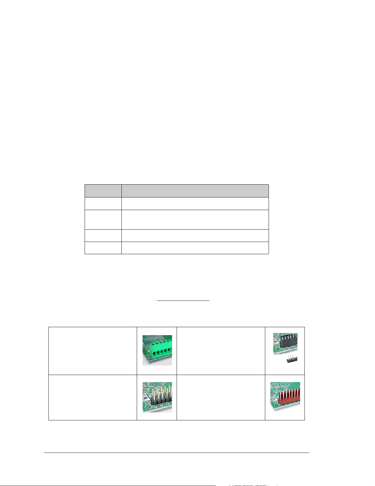
In addition to the standard screw-terminal connectors supplied on BL2000 boards, IDC
headers, bottom-mount connectors, and polarized friction-lock terminals may be factoryinstalled instead. Visit our Web site at www.zworld.com
or contact your Z-World sales
representative or authorized distributor for further information.
Standard screw terminals, accept
up to 14 AWG (1.5 mm
2
) wire
“Bottom-mount connector” to
mount BL2000 directly on 0.1"
pitch pins located on motherboard
2 × 17 IDC headers, 0.1" pitch
2 Wildcat (BL2000)
Polarized friction-lock terminals,
0.1" pitch
Page 7
1.3 Development and Evaluation Tools
1.3.1 Tool Kit
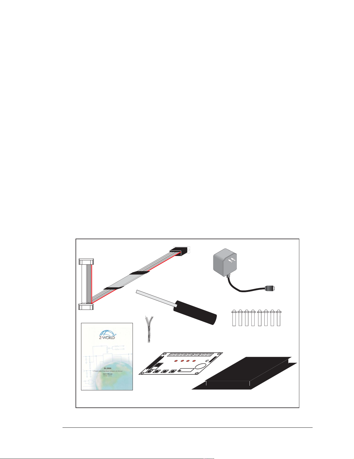
A T ool Kit contains the hardware essentials you will need to use your own BL2000 singleboard computer. The items in the Tool Kit and their use are as follows:
• BL2000 User’s Manual with schematics (this document).
• Dynamic C CD-ROM, with complete product documentation on disk.
• Programming cable, used to connect your PC serial port to the BL2000.
• AC adapter, used to power the BL2000
. An AC adapter is supplied with tool kits sold in
the North American market. If you are using another power supply, it must provide 9 to
40 V DC
.
• Demonstration Board with pushbutton switches and LEDs. The Demonstration Board
can be hooked up to the BL2000 to demonstrate the I/O and the TCP/IP capabilities of
the BL2000.
• Wire assembly to connect Demonstration Board to BL2000.
• Plastic enclosure with four screws and eight customer-installable light pipes.
• Screwdriver.
• Rabbit 2000 Processor Easy Reference poster.
• Registration card.
DIAG
Programming
Cable
Screwdriver
AC Adapter
(North American
kits only)
PROG
Demo Board
Wiring Harness
·
·
S
S
G
W
W
N
D
2
1
H2
LED1 LED2 LED3 LED4
· ·
1-2
· ·
3-4
DEMO BOARD
· ·
5-6
SW1 SW2 SW3 SW4
·
1
L
K
S
+
S
E
5
W
W
V
D
D
4
3
2
1
·
·
·
·
H
·
·
·
·
1
2
8
6
4
-
-
-
7
5
3
L
E
3
BUZZER
1
B
L
L
E
E
U
D
D
Z
4
Z
E
R
J
·
·
·
·
·
·
·
·
·
LED Light Pipes
Demo Board
User's Manual
Plastic Enclosure
Figure 1. BL2000 Tool Kit
User’s Manual 3
Page 8

1.3.2 Software
The BL2000 is programmed using version 7.04 or later of Z-World’s Dynamic C. A com-
patible version is included on the Tool Kit CD-ROM.
Z-World also offers add-on Dynamic C modules containing the popular µC/OS-II realtime operating system, as well as PPP, Advanced Encryption Standard (AES), and other
select libraries. In addition to the Web-based technical support included at no extra charge,
a one-year telephone-based technical support module is also available for purchase. Visit
our Web site at www.zworld.com
or contact your Z-World sales representative or autho-
rized distributor for further information.
4 Wildcat (BL2000)
Page 9
1.4 CE Compliance
Equipment is generally divided into two classes.
CLASS A CLASS B
Digital equipment meant for light industrial use Digital equipment meant for home use
Less restrictive emissions requirement:
less than 40 dB µV/m at 10 m
(40 dB relative to 1 µV/m) or 300 µV/m
More restrictive emissions requirement:
30 dB µV/m at 10 m o r 100 µV/m
These limits apply over the range of 30–230 MHz. The limits are 7 dB higher for frequencies above 230 MHz. Although the test range goes to 1 GHz, the emissions from Rabbitbased systems at frequencies above 300 MHz are generally well below background noise
levels.
The BL2000 single-board computer has been tested and was found to
be in conformity with the following applicable immunity and emission
standards. The BL2010, BL2020, and BL2030 single-board computers
are also CE qualified as they are sub-versions of the BL2000 singleboard computer. Boards that are CE-compliant have the CE mark.
NOTE: Earlier versions of the BL2000 sold before 2003 that do not have the CE mark
are not CE-compliant.
Immunity
The BL2000 series of single-board computers meets the following EN55024/1998 immunity standards.
• EN61000-4-3 (Radiated Immunity)
• EN61000-4-4 (EFT)
• EN61000-4-6 (Conducted Immunity)
Additional shielding or filtering may be required for a heavy industrial environment.
Emissions
The BL2000 series of single-board computers meets the following emission standards
using the enhanced-EMI PCB, Part# 175-0224 Rev. A, and the 668-0003 Rev. A Rabbit
2000 microprocessor.
• EN55022:1998 Class B
• FCC Part 15 Class B
Your results may vary, depending on your application, so additional shielding or filtering
may be needed to maintain the Class B emission qualification.
User’s Manual 5
Page 10

1.4.1 Design Guidelines
Note the following requirements for incorporating the BL2000 series of single-board computers into your application to comply with CE requirements.
General
• The power supply provided with the Tool Kit is for development purposes only. It is the
customer’s responsibility to provide a CE-compliant power supply for the end-product
application.
• When connecting the BL2000 single-board computer to outdoor cables, the customer is
responsible for providing CE-approved surge/lighting protection.
• Z-World recommends placing digital I/O or analog cables that are 3 m or longer in a
metal conduit to assist in maintaining CE compliance and to conform to good cable
design practices.
• When installing or servicing the BL2000, it is the responsibility of the end-user to use
proper ESD precautions to prevent ESD damage to the BL2000.
Safety
• All inputs and outputs to and from the BL2000 series of single-board computers must
not be connected to voltages exceeding SELV levels (42.4 V AC peak, or 60 V DC).
• The lithium backup battery circuit on the BL2000 single-board computer has been
designed to protect the battery from hazardous conditions such as reverse charging and
excessive current flows. Do not disable the safety features of the design.
1.4.2 Interfacing the BL2000 to Other Devices
Since the BL2000 series of single-board computers is designed to be connected to other
devices, good EMC practices should be followed to ensure compliance. CE compliance is
ultimately the responsibility of the integrator. Additional information, tips, and technical
assistance are available from your authorized Z-World distributor, and are also available
on our Web site at www.zworld.com
.
6 Wildcat (BL2000)
Page 11
2. GETTING S TARTED
Chapter 2 explains how to connect the programming cable and
power supply to the BL2000.
2.1 BL2000 Connections
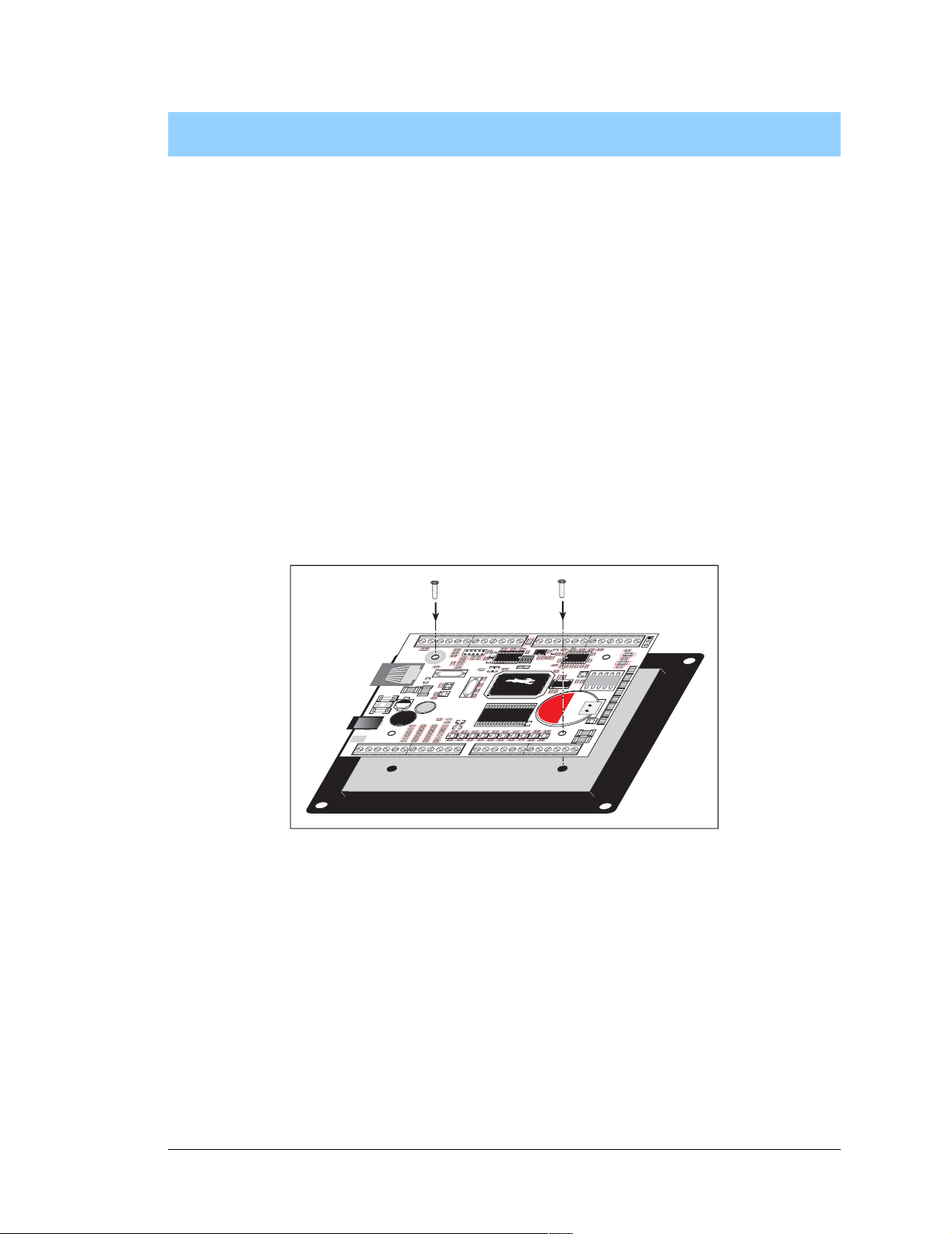
1. Attach the BL2000 to the plastic enclosure base.
Position the BL2000 over the plastic enclosure base as shown below in Figure 2. Attach
the BL2000 to the base at the top left and bottom right positions using the two 4-40 × ¼
screws supplied with the enclosure.
GND RST- IN1 IN0 485- 485+ RXD2 TXD2 RXD1 TXD1 AGNDDAC1 DAC0 ADC8ADC7 ADC6 ADC5ADC4 ADC3 ADC2ADC1 ADC0+RAW +K
J1
J2
GND
GN D
GND GND
R1
J6
C23
D1
C25
T
C28
V
S
1
+
D2
14
+
L1
23
C
3
3
R
R
3
3
6
7
R
R
5
J7
POWER IN
GND
J8
J10
IN3IN2 IN4 IN5 IN6 IN7 IN8 IN9 IN10 OUT8 OUT9 GND GNDOUT0 OUT1OUT2 OUT3 OUT4OUT5 OUT6 OUT7 NC
5
0
1
C
C
3
3
8
9
R
R
5
5
5
4
R
R
5
5
9
8
GN D
J5
R4
R6
R12
C10
C80
R20
R130
R16
R15
C20
R19
C16
C19
Y3
Y2
C17
C24
U4
R
1
5
1
R33
C
3
4
2
C
4
0
R
5
6
R
6
0
R
2
8
C
2
Q2
7
R30
C29
R32
R34
R35
R40
C31
R31
D3
C
C
3
3
6
5
R
R
R41
R42
3
3
9
8
D4
D5
R
R
5
5
3
C
4
1
R
5
7
R
6
1
C46
C44
C43
C45
GNDGNDGNDGND
GND
GND GND
R13
R153
U5
C
2
2
R
2
7
R43 R44
D6
C47
GND
C1
R9
R154
C18
9
0
R45
D7 D8 D9
C85
J4
J3
AGND
AGND
AGND
C2
C3
C75
R5
C79
U2
C8
R7
C4
R
R
R
C
J
1
P
1
1
1
5
1
1
0
1
R17
7
U1
C13
JP2
C76
C
R152
1
R22
4
C21
R
2
6
4
5
1
5
U6
R46
C50
C49C48
GND
Y1
4
0
1432
R29
C26
D
Q3
G
Battery
Q5
CAUTION
C32
R48
R47
R49
D11 D12
D10
C51
C52
GND
GND
GN D
NO
COM
AGND
AG ND
AGND
R2
R3
C78
C
1
5
R
2
C77
Q1
3
56
R
R
2
2
5
6
Q4
S
Q6
4
2
GND
J11
J9
J12
C5
C7
+
R8
C9
U3
R14
R18
C12
D
R21
S
R
1
W
P
D
1
K
S
N
2
L
D
1
S
0
T
3
C
A
D
0
T
S
U
4
O
K1
D
S
1
BT1
T
5
U
O
D
2
+
S
T
6
U
O
D
3
S
T
7
U
+
O
D
A
B
DS8
C
3
7
C
Figure 2. Attach BL2000 to Plastic Enclosure Base
The plastic enclosure base facilitates handling the BL2000 during development, and provides an attractive mounting alternative. Alternatively, you may wish to use standoffs to
protect the components on the other side of the board. The plastic enclosure is offered as a
separate option when individual BL2000 boards are purchased.
NOTE: Appendix B, “Plastic Enclosure,” provides additional information and specifica-
tions for the plastic enclosure.
User’s Manual 7
Page 12
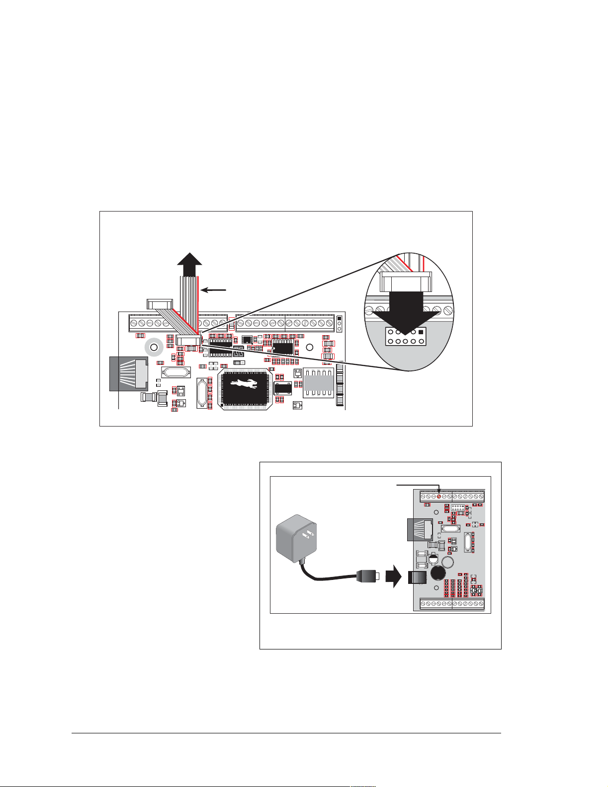
2. Connect the programming cable to download programs from your PC and to debug the
BL2000.
Connect the 10-pin
PROG connector of the programming cable to header J5 on the BL2000.
Ensure that the colored edge lines up with pin 1 as shown. (Do not use the DIAG connector,
which is used for monitoring only, as explained in Appendix E, “Programming Cable.”)
Connect the other end of the programming cable to a COM port on your PC. Make a note of
the port to which you connect the cable, as Dynamic C will need to ha ve this parameter configured. Note that COM1 on the PC is the default COM port used by Dynamic C.
To
PC COM port
Programming Cable
Colored edge
DIAG
GND RST- IN1 IN0 485- 485+ RXD2 TXD2 RXD1 TXD1 AGND DAC1 DAC0 ADC8 ADC7 ADC6 ADC5 ADC4 ADC3 ADC2 ADC1 ADC0+RAW +K
J1
J2
GND GND
R1
GND
GN D
GND GND
R13
J5
R4
R6
PROG
R12
C10
C80
R20
C20
R130
R16
R15
R19
C16
Y3
C17
C24
U4
C25
R151
R30
Q2
J6
C23
C85
J4
J3
AGND
AGND
C2
C3
C75
C1
R9
R153
C19
U5
Y2
R28
C27
U2
C8
R157
R10
JP1
U1
R154
C18
JP2
R27C22
65
90
15
AG ND
AGND
R5
C79
R2
C78
R7
C4
R11
C11
R17
C13
C76
C14
R152
R22
C21
R24
40
1432
R29
C26
AGND
AGND
R3
C5
R8
U3
R18
C15
R23
C77
Q1
56
Y1
R25
R26
Q4
J12
C7
+
C9
R14
C12
DS1
R21
PWRLNKACTOUT 0
1
10
DS4DS3DS2
K1
PROG
J5
Figure 3. Programming Cable Connections
3. Connect the power supply.
Plug the DC end of the power supply into jack J7, which is labeled
POWER IN, as shown in Figure 4.
4. Apply power.
Plug in the AC adapter. If you are
using your own power supply, it
must provide 9 V to 40 V DC—
voltages outside this range could
RESET
PIN
GND RST- IN1 IN0 485- 485+ RXD2 TXD2 RXD1 TXD1+RAW +K
J1
J2
GND
GN D
GND GND
R4
R6
R1
R12
C10
R20
C20
C16
C17
C24
R151
J6
C23
D1
C25
TVS1
C28
+
D2
14
+
L1
23
C33
J7
J8
J10
POWER IN
R36
C38R50
R54
R58
GND
GN D
IN3IN2 IN4 IN5 IN6 IN7 IN8 IN9 IN10 OUT8 OUT9 GND
J5
R16
R19
U4
R30
C29
C34
R37
R51
C39
R55
R59
damage the BL2000.
The green PWR LED and the red
Figure 4. Power Supply Connection
BAD LED should come on, indicat-
ing that the BL2000 is now ready to be used.
NOTE: A hardware RESET is done by unplugging the AC adapter , th en plu gging it back i n, or
by momentarily grounding the board r ese t i nput at pin 9 on screw terminal header J 2.
C80
Q2
C31
R33
GND GND
R13
R130
R15
Y3
R31
C35
R38
R52
C40
R56
R60
C1
R9
R153
R154
C19
U5
Y2
R27C22
R28
C27
R32
R34
R35
R40
D3
C36
R39
R41
D4
C41R53
R57
R61
C44
C43
GNDGNDGNDGND
GND
8 Wildcat (BL2000)
Page 13

2.2 Installing Dynamic C
If you have not yet installed Dynamic C version 7.04 (or a later version), do so now by
inserting the Dynamic C CD in your PC’s CD-ROM drive. The CD will auto-install unless
you have disabled auto-install on your PC.
If the CD does not auto-install, click
browse for the Dynamic C
setup.exe file on your CD drive. Click OK to begin the
installation once you have selected the
Start > Run from the Windows St art button and
setup.exe file.
The online documentation is installed along with Dynamic C, and an icon for the documentation menu is placed on the workstation’s desktop. Double-click this icon to reach the
menu. If the icon is missing, create a new desktop icon that points to default.htm in the
docs folder, found in the Dynamic C installation folder.
The latest versions of all documents are always available for free, unregistered download
from our web sites as well.
The Dynamic C User’s Manual provides detailed instructions for the installation of
Dynamic C and any future upgrades.
NOTE: If you have an earlier version of Dynamic C already installed, the default instal-
lation of the la te r ver sion wi ll b e in a different fold er, and a sep arate icon will appear on
your desktop.
User’s Manual 9
Page 14

2.3 St arting Dynamic C
Once the BL2000 is connected to your PC and to a power source, start Dynamic C by dou-
ble-clicking on the Dynamic C icon or by double-clicking on dcrabXXXX.exe in the Dynamic
C root directory, where XXXX are version-specific characters.
Dynamic C defaults to using the serial port on your PC that you specified during installation. If the port setting is correct, Dynamic C should detect the BL2000 and go through a
sequence of steps to cold-boot the BL2000 and to compile the BIOS. (Some versions of
Dynamic C will not do the initial BIOS compile and load until the first time you compile a
program.)
If you receive the message
No Rabbit Processor Detected, the programming
cable may be connected to the wrong COM port, a connection may be faulty, or the target
system may not be powered up. First, check both ends of the programming cable to ensure
that it is firmly plugged into the PC and the programming port.
If there are no faults with the hardware, select a different COM port within Dynamic C.
From the
Options menu, select Communications. Select another COM port from the list,
then click OK. Press <Ctrl-Y> to force Dynamic C to recompile the BIOS. If Dynamic C
still reports it is unable to locate the target system, repeat the above steps until you locate the
active COM port. You should receive a Bios compiled successfully message
once this step is completed successfully.
If Dynamic C appears to compile the BIOS successfully, but you then receive a communication error message when you compile and load a sample program, it is possible that your
PC cannot handle the higher program-loading baud rate. Try changing the maximum
download rate to a slower baud rate as follows.
• Locate the Serial Options dialog in the Dynamic C Options > Communications
menu. Select a slower Max download baud rate.
If a program compiles and loads, but then loses target communication before you can
begin debugging, it is possible that your PC cannot handle the default debugging baud
rate. Try lowering the debugging baud rate as follows.
• Locate the
Serial Options dialog in the Dynamic C Options > Communications
menu. Choose a lower debug baud rate.
10 Wildcat (BL2000)
Page 15

2.4 PONG.C
You are now ready to test your set-up by running a sample program.
Find the file
open it with the
PONG.C, which is in the Dynamic C SAMPLES folder. To run the program,
File menu (if it is not still open), compile it using the Compile m enu, and
then run it by selecting Run in the Run menu. The STDIO window will open and will display a small square bouncing around in a box.
This program does not test the serial ports, the I/O, or the TCP/IP part of the board, but
does ensure that the board is basically functional. The sample program described in
Section 5.3, “Run the PINGME.C Sample Program,” tests the TCP/IP portion of the
board.
2.5 Where Do I Go From Here?
NOTE: If you purchased your BL2000 through a distributor or Z-World partner, contact
the distributor or Z-World partner first for technical support.
If there are any problems at this point:
• Check the Z-W orld Technical Bulletin Board at www.zworld.com/support/bb/.
• Use the T echn ical Support e-mail form at www.zworld.com/support/support_submit.htm l.
If the sample program ran fine, you are now ready to go on to explore other BL2000 features and develop your own applications.
Chapter 3, “Subsystems,” provides a description of the BL2000’s features, Chapter 4,
“Software,” describes the Dynamic C software libraries and introduces some sample programs, and Chapter 5, “Using the TCP/IP Features,” explains the TCP/IP features.
User’s Manual 11
Page 16

12 Wildcat (BL2000)
Page 17
3. SUBSYSTEMS
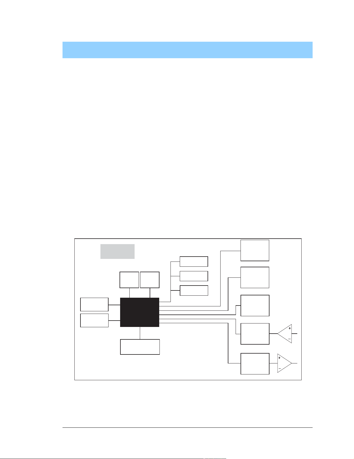
Chapter 3 describes the principal subsystems for the BL2000.
• Digital I/O
• Relay Outputs
• Serial Communication
• A/D Converter Inputs
• D/A Converter Outputs
• Memory
• External Interrupts
Figure 5 shows these Rabbit-based subsystems designed into the BL2000.
SRAM
Flash
BL2000
32 kHz
osc
RABBIT
Ethernet
Programming
Port
11 MHz
osc
RS-232
RS-485
2000
Figure 5. BL2000 Subsystems
Digital
Inputs
Digital
Outputs
Relay
Output
A/D
Converter
D/A
Converter
User’s Manual 13
Page 18
3.1 BL2000 Pinouts
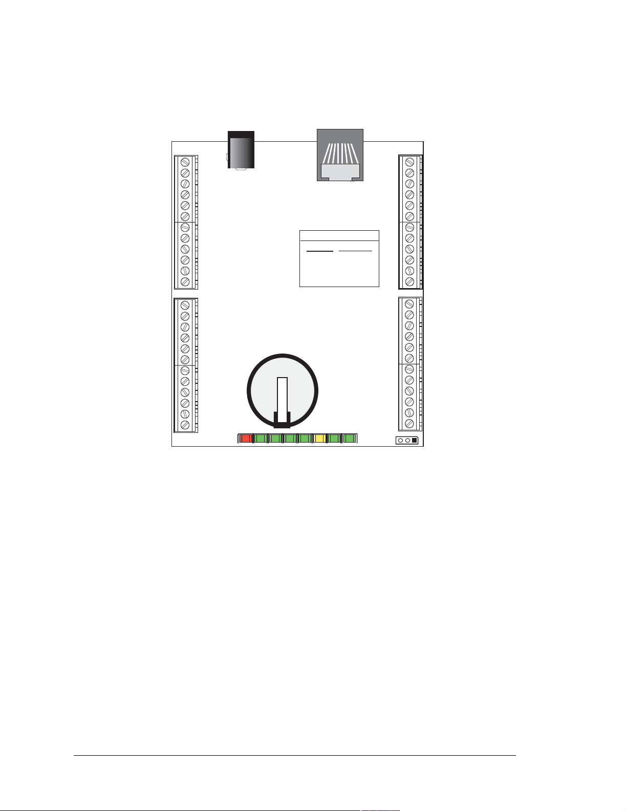
The BL2000 pinouts are shown in Figure 6(a) and Figure 6(b).
IN10
OUT8
OUT9
GND
OUT0
OUT1
OUT2
OUT3
OUT4
OUT5
OUT6
OUT7
COM
GND/VCC
IN2
IN3
IN4
IN5
IN6
IN7
IN8
IN9
NO
NC
1
J8
2
J8
3
4
5
6
7
8
9
10
11
12
1
2
J8
3
4
5
6
7
8
9
10
11
12
J9
J7
Battery
J6
Serial Port Nomenclature
TXD1
RXD1
TXD2
RXD2
Rabbit 2000
TxB
RxB
TxC/RTS
RxC/CTS
HeaderJ2
J2
J4
12
11
10
9
8
7
6
5
4
3
2
1
12
11
10
9
8
7
6
5
4
3
2
1
+RAW
GND
J8
+K
/RESET
IN1
IN0
485
485+
RXD2
TXD2
RXD1
TXD1
AGND
DAC1
J8
DAC0
ADC8
ADC7
ADC6
ADC5
ADC4
ADC3
ADC2
ADC1
ADC0
J12
BAD OUT3 OUT2 OUT1 OUT0 ACT LNK PWR
DS8
DS7
DS6
DS5
DS4
DS3
DS2
DS1
GND
GND
VBATEXT
Figure 6(a). BL2000 Pinouts (screw-terminal headers)
14 Wildcat (BL2000)
Page 19
3.1.1 Headers and Screw Terminals
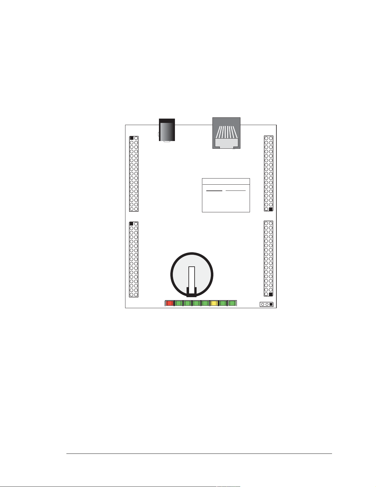
All BL2000 models are equipped with 1 × 12 screw terminal strips (J2, J4, J8, and J9) and
a 2-pin power jack (J7). The BL2000 and BL2010 also have the RJ-45 Ethernet jack (J6).
There is provision on the circuit board to accommodate 2 × 17 IDC headers or 1 × 17
friction-lock connectors with a pitch of 0.1" instead of the screw terminal strips. The
pinouts for these connectors are shown in Figure 6(b).
GND
GND
GND
GND
IN10
OUT8
GND
OUT9
GND
OUT0
OUT1
GND
OUT2
OUT3
GND
OUT4
OUT5
GND
OUT6
OUT7
GND
COM
GND
GND/VCC
IN2
IN3
IN4
IN5
IN6
IN7
IN8
IN9
NO
NC
1
3
5
7
9
11
13
15
17
19
21
23
25
27
29
31
33
1
3
5
7
9
11
13
15
17
19
21
23
25
27
29
31
33
J10
J11
J7
Battery
J6
Serial Port Nomenclature
TXD1
RXD1
TXD2
RXD2
Rabbit 2000
TxB
RxB
TxC/RTS
RxC/CTS
HeaderJ2
J1
J3
33
31
29
27
25
23
21
19
17
15
13
11
33
31
29
27
25
23
21
19
17
15
13
+RAW
GND
GND
+K
/RESET
GND
IN1
IN0
GND
485
485+
GND
9
RXD2
7
TXD2
5
GND
3
RXD1
1
TXD1
AGND
DAC1
AGND
DAC0
ADC8
AGND
ADC7
ADC6
AGND
ADC5
ADC4
11
AGND
9
ADC3
7
ADC2
5
AGND
3
ADC1
1
ADC0
J12
BAD OUT3 OUT2 OUT1 OUT0 ACT LNK PWR
DS8
DS7
DS6
DS5
DS4
DS3
DS2
DS1
GND
GND
VBATEXT
Figure 6(b). BL2000 Pinouts (other 0.1" headers)
3.1.2 Power Supply Pins
Instead of connecting an AC adapter to the power supply jack, J7, the input power supply
(9 V to 40 V DC) may be connected to pins 12 and 11 on header J2 (see Figure 6(a) or
Figure 6(b)).
Pin 12 on header J9 or J10 is normally GND by factory default, but may be changed to
Vcc by removing resistor R161 and installing resistor R160. See Appendix C, “Power
Supply,” for more information on this configuration and for information on backupbattery options.
User’s Manual 15
Page 20
3.2 Digital I/O
3.2.1 Digital Inputs
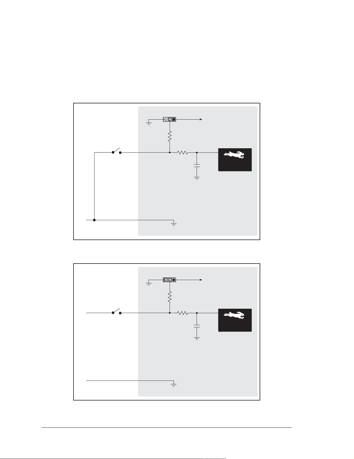
The BL2000 has 11 digital inputs, IN0–IN10, each of which is protected over a range of
–36 V to +36 V. The inputs are factory-configured to be pulled up to +5 V, but they can
also be pulled down by moving the surface-mounted jumper at JP6 as shown in Figure 7.
GND
JP6
JP6
3
1
27 kW
22 kW
Vcc
10 nF
Factory
Default
Rabbit 2000
Microprocessor
Figure 7(a). BL2000 Digital Inputs [Pulled Up—JP6(1–2) connected]
JP6
JP6
3
1
Vcc
27 kW
+5 V
GND
22 kW
10 nF
Rabbit 2000
Microprocessor
Figure 7(b). BL2000 Digital Inputs [Pulled Down—JP6(2–3) connected]
16 Wildcat (BL2000)
Page 21
JP6
JP6
3
1
27 kW
Vcc
22 kW
10 nF
Rabbit 2000
Microprocessor
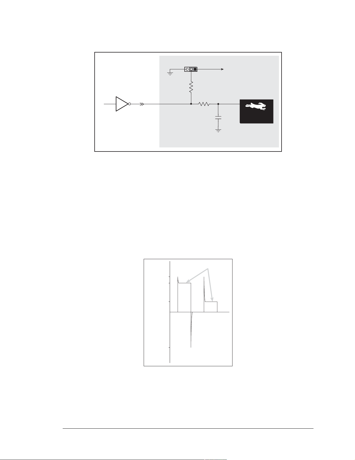
Figure 7(c). Example of Logic Gate Driving BL2000 Digital Input
The actual switching threshold is approximately 2.40 V for channels IN0–IN10. Anything
below this value is a logic 0, and anything above is a logic 1.
The A/D converter inputs can be used as additional digital inputs using the parameters
specified for the digIn software function call. The default threshold for channels IN11–
IN21 is also set to 2.40 V, but may be changed by adding two lines to your program as discussed for the digIn software function call.
The digital inputs are each fully protected over a range of -36 V to +36 V, and can handle
short spikes of ±40 V.
Normal Switching
Levels
Spikes
+40 V
+36 V
Spikes
+3.3 V
Digital Input Voltage
40 V
Spikes
Figure 8. BL2000 Digital Input Protected Range
User’s Manual 17
Page 22
3.2.2 Digital Outputs
The BL2000 has 10 digital outputs, OUT0–OUT9, each of which can either sink or source
up to 200 mA, depending on how the outputs are configured. On boards that carry the CE
mark, OUT8 and OUT9 are each capable of sinking up to 750 mA.
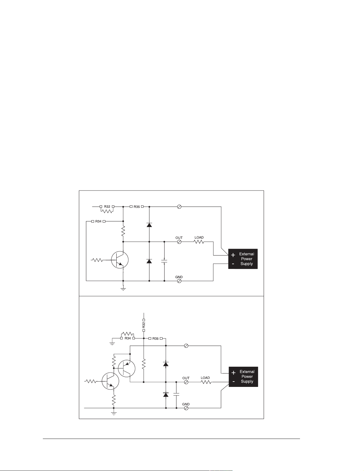
Each output can be configured individually as either a sinking or a sourcing output as shown
in Figure 9. The outputs can be pulled as a group to Vcc, +K, or GND through 27 kΩ resistors. Tie the outputs high to either Vcc or +K when using the outputs as sinking outputs (via
0 Ω resistors at R32 or R35 respectively), or tie the outputs to GND via R34 when using the
outputs as sourcing outputs. +K is an externally supplied voltage of up to 40 V DC, and is
used primarily in combination with current sourcing outputs, and must also be connected to
an external supply when an inductive load is connected to a sinking output.
NOTE: Remove the 27 kΩ resistors (R143–R150) from the output circuits if no pull-
up/down is required to avoid leakage between the outputs. These resistors are located
on the bottom side of the BL2000 board above the solder points for screw terminal
header J9.
SINKING OUTPUTFactory Default
Vcc
0 W
27 kW
K
SOURCING OUTPUTSpecial Order
Vcc
0 W
K
27 kW
Figure 9. BL2000 Digital Outputs
18 Wildcat (BL2000)
Page 23
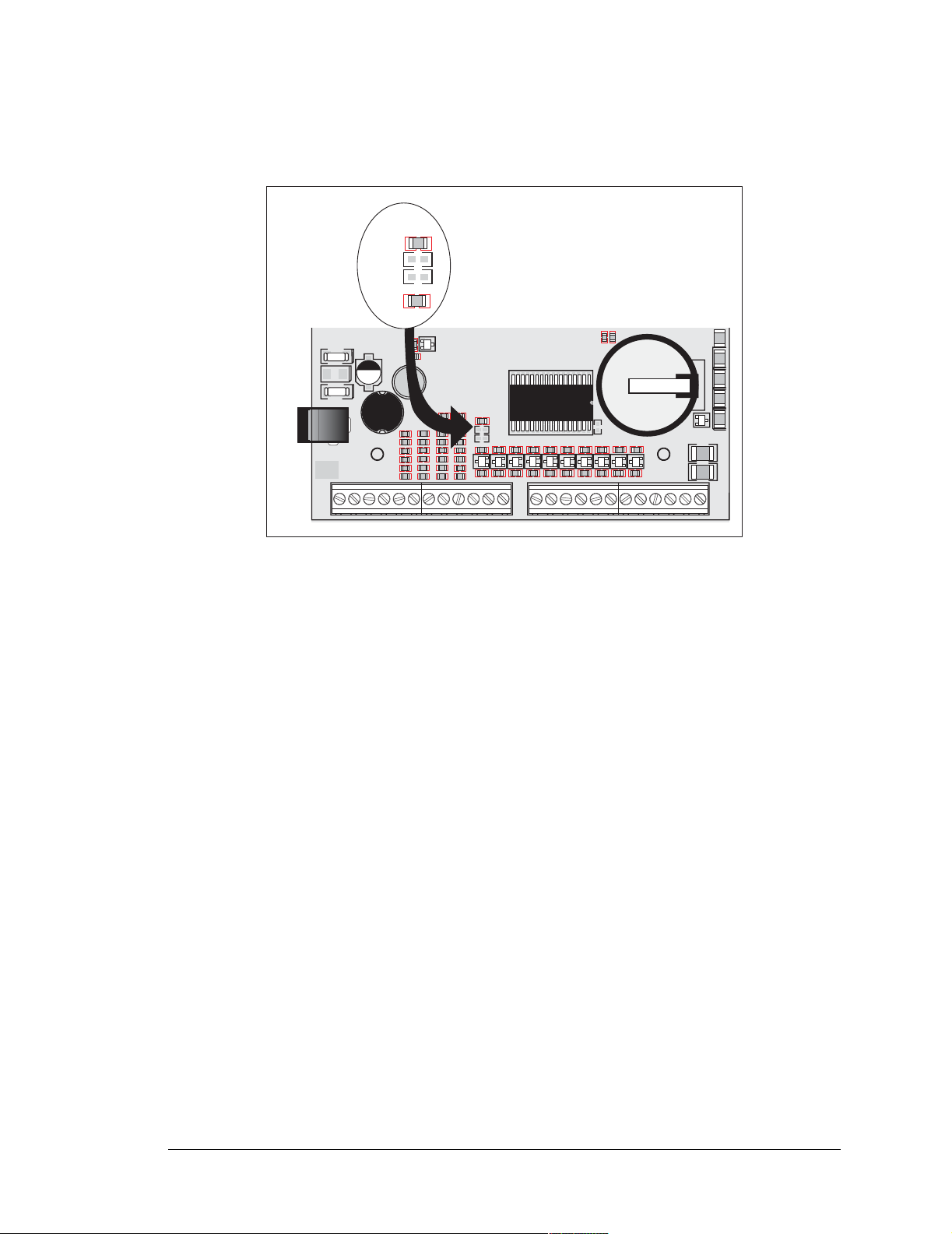
The locations of the output pull-up/pull-down select resistors R32, R34, and R35 are
shown in Figure 10.
R32
R34
R35
D1
TVS1
D2
C25
C28
+
14
23
J7
POWER IN
GND
J8
J10
IN3IN2 IN4 IN5 IN6 IN7 IN8 IN9 IN10 OUT8 OUT9 GND GND/VCCOUT0 OUT1 OUT2 OUT3 OUT4 OUT5 OUT6 OUT7 NCNO
Q2
R30
C29
+
L1
C33
R36
C38R50
R54
R58
GN D
R32
R34
R35
R40
C31
R31
D3
R33
C34
C36
C35
R37
R39
R38
R41
R42
D4
R51
R52
C39
C40
R55
R56
R60
R59
D5
C41R53
R57
R61
C44
C43
C45
GNDGNDGNDGND
GND
SRAM
R45
R43 R44
D7 D8 D9
D6
C47
C46
GND
U6
R46
C49C48
R29
C26
C32
R47
D10
C50
GND
D
Q3
Battery
Q5
R48
R49
D11 D12
C51
C52
GN D
Q4
S
G
GND
DS4
OUT 0OUT 1OUT 2OUT 3BAD
DS5
BT1
DS6
+
DS7
+
DS8
Q6
C37
C42
GND
GND
J11
J9
COM
Figure 10. Locations of Resistors R32, R34, and R35
All BL2000 models are factory-configured with sinking outputs and pull-up resistors tied
to Vcc via a 0 Ω resistor at R32.
User’s Manual 19
Page 24
3.3 Relay Outputs
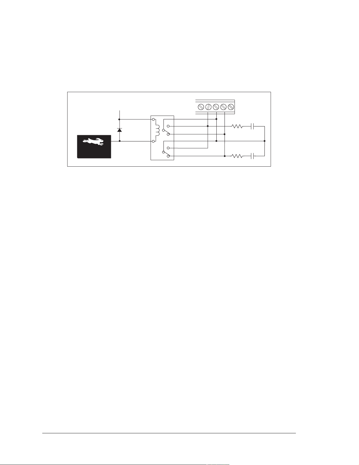
Figure 11 shows the BL2000 relay contact connections. A diode across the coil provides a
return path for inductive spikes, and snubbers across the relay contacts protect the relay
contacts from inductive spikes.
10
9
11
47 W
47 W
J9
100 nF
100 nF
Vcc
COM
8
7
NO
9
NC
COM
3
4
NO
2
NC
Rabbit 2000
Microprocessor
1
10
Figure 11. BL2000 Relay Output Contact Connections
The relay is driven by PA0, which is the same Rabbit 2000 parallel port that drives OUT0
and LED DS4. OUT0 therefore works in parallel with the relay output.
The relay included on the BL2000 has contacts rated for 1 A @ 30 V DC or 300 mA @
120 V AC. When using the BL2000 in a CE-certified application, the voltages handled by
the relay must not exceed SELV levels (42.4 V AC peak, or 60 V DC).
20 Wildcat (BL2000)
Page 25
3.4 Serial Communication
The BL2000 has one RS-232 serial channel (with RTS/CTS) or two RS-232 (3-wire)
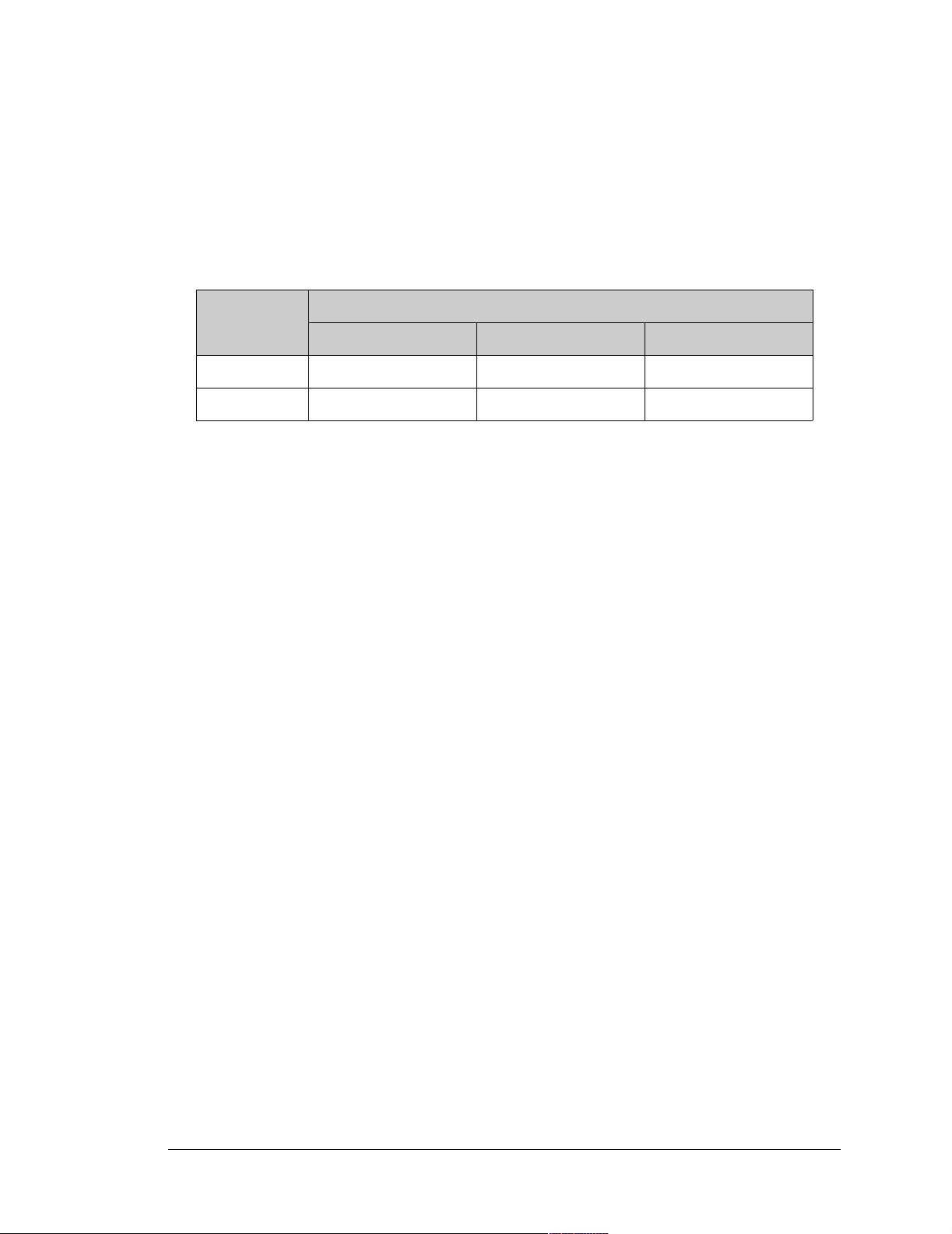
channels, one RS-485 serial channel, and one CMOS serial channel. The RS-232 channel(s) are configured with the serMode software function call. Table 2 summarizes the
options.
Table 2. Serial Communication Configurations
Serial Port
Mode
B C D
0 RS-232, 3-wire RS-232, 3-wire RS-485
1 RS-232, 5-wire CTS/RTS RS-485
All four serial ports operate in an asynchronous mode. An asynchronous port can handle 7
or 8 data bits. A 9th bit address scheme, where an additional bit is sent to mark the first
byte of a message, is also supported. Serial Port A can be operated alternately in the
clocked serial mode. In this mode, a clock line synchronously clocks the data in or out.
Either of the two communicating devices can supply the clock. The BL2000 series boards
typically use all four ports in the asynchronous serial mode. Serial Ports B and C are used
for RS-232 communication, and Serial Port D is used for RS-485 communication. The
BL2000 uses an 11.0592 MHz crystal, which is doubled to 22.1184 MHz. At this frequency, the BL2000 supports standard baud rates up to a maximum of 230,400 bps.
3.4.1 RS-232
The BL2000 RS-232 serial communication is supported by an RS-232 transceiver , U1. U1
provides the voltage output, slew rate, and input voltage immunity required to meet the
RS-232 serial communication protocol. Basically, the chip translates the Rabbit 2000’s
CMOS/TTL signals to RS-232 signal levels. Note that the polarity is reversed in an
RS-232 circuit so that a +5 V output becomes approximately -10 V and 0 V is output as
+10 V. U1 also provides the proper line loading for reliable communication.
RS-232 can be used effectively at this baud rate for distances up to 15 m.
3.4.2 RS-485
The BL2000 has one RS-485 serial channel, which is connected to the Rabbit 2000 Serial
Port D through U8, an RS-485 transceiver.
protocol. The chip’s slew rate limiters provide for a maximum baud rate of
U8 supports the RS-485 serial communication
230,400
bps
,
which allows for a network of up to 300 m (or 1000 ft). The half-duplex communication
uses the Rabbit 2000’s PB6 pin to control the transmit enable on the communication line.
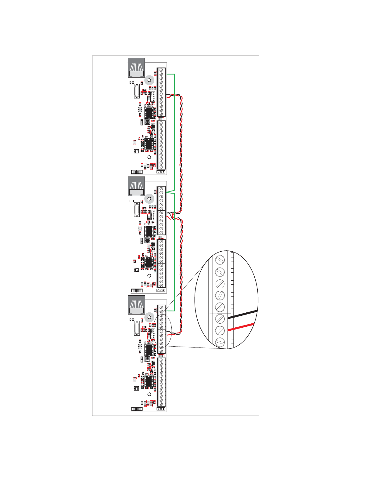
The BL2000 can be used in an RS-485 multidrop network. Connect the 485+ to 485+ and
485– to 485– using single twisted-pair wires (nonstranded, tinned) as shown in Figure 12.
Note that a common ground is recommended.
User’s Manual 21
Page 26
J2
J1
GND GND
R1
GND RST- IN1 IN0 485- 485+ RXD2 TXD2 RXD1 TXD1 AGND DAC1 DAC0ADC8 ADC7 ADC6 ADC5 ADC4 ADC3 ADC2 ADC1 ADC0+RAW +K
C20
GND
R4
C17
R6
R20
C10
C16
R12
GN D
R19
R16
J5
C80
Y3
Y2
C19
U5
C21
R24
DS2
PWRLNK
GND GND
R130
R13
R15
R9
C1
R153
R154
C18
U1
C2
C3
C8
AGND
U2
JP1
JP2
R157
AGND
C75
R10
R11
C13
R5
C11
R17
C4
R152
C79
C76
AGND
R7
R2
R22
C78
C14
AG ND
R23
C77
R3
Q1
AGND
R8
R18
C15
U3
C5
R21
C7
AGND
+
R14
DS1
C12
J12
C9
J2
GND GND
R1
C20
GND
R4
C17
R6
R20
C10
C16
R12
GN D
R19
R16
J5
C80
Y3
Y2
C19
U5
C21
R24
DS2
PWRLNK
GND GND
R130
R13
R15
R9
C1
R153
R154
C18
U1
C2
C3
C8
AGND
U2
JP1
JP2
R157
AGND
C75
R10
R11
C13
R5
C11
R17
C4
R152
C79
C76
AGND
R7
R2
R22
C78
C14
AG ND
R23
C77
R3
Q1
AGND
R8
R18
C15
U3
C5
R21
C7
AGND
+
R14
DS1
C12
J12
C9
J2
GND GND
R1
C20
GND
R4
C17
R6
R20
C10
C16
R12
GN D
R19
R16
J5
C80
Y3
Y2
C19
U5
C21
R24
DS2
PWRLNK
GND GND
R130
R13
R15
R9
C1
R153
R154
C18
U1
C2
C3
C8
AGND
U2
JP1
JP2
R157
AGND
C75
R10
R11
C13
R5
C11
R17
C4
R152
C79
C76
AGND
R7
R2
R22
C78
C14
AG ND
R23
C77
R3
Q1
AGND
R8
R18
C15
U3
C5
R21
C7
AGND
+
R14
DS1
C12
J12
C9
Ground recommended
C85
J4
J3
J1
GND RST- IN1 IN0 485- 485+ RXD2 TXD2 RXD1 TXD1 AGND DAC1 DAC0ADC8 ADC7 ADC6 ADC5 ADC4 ADC3 ADC2 ADC1 ADC0+RAW +K
C85
J4
J3
10
9
J1
GND RST- IN1 IN0 485- 485+ RXD2 TXD2 RXD1 TXD1 AGND DAC1 DAC0ADC8 ADC7 ADC6 ADC5 ADC4 ADC3 ADC2 ADC1 ADC0+RAW +K
C85
J4
J3
8
7
6
5
J2
GN
+K
/RESET
IN1
IN0
485
485+
RX
Figure 12. Multidrop BL2000 Network
22 Wildcat (BL2000)
Page 27
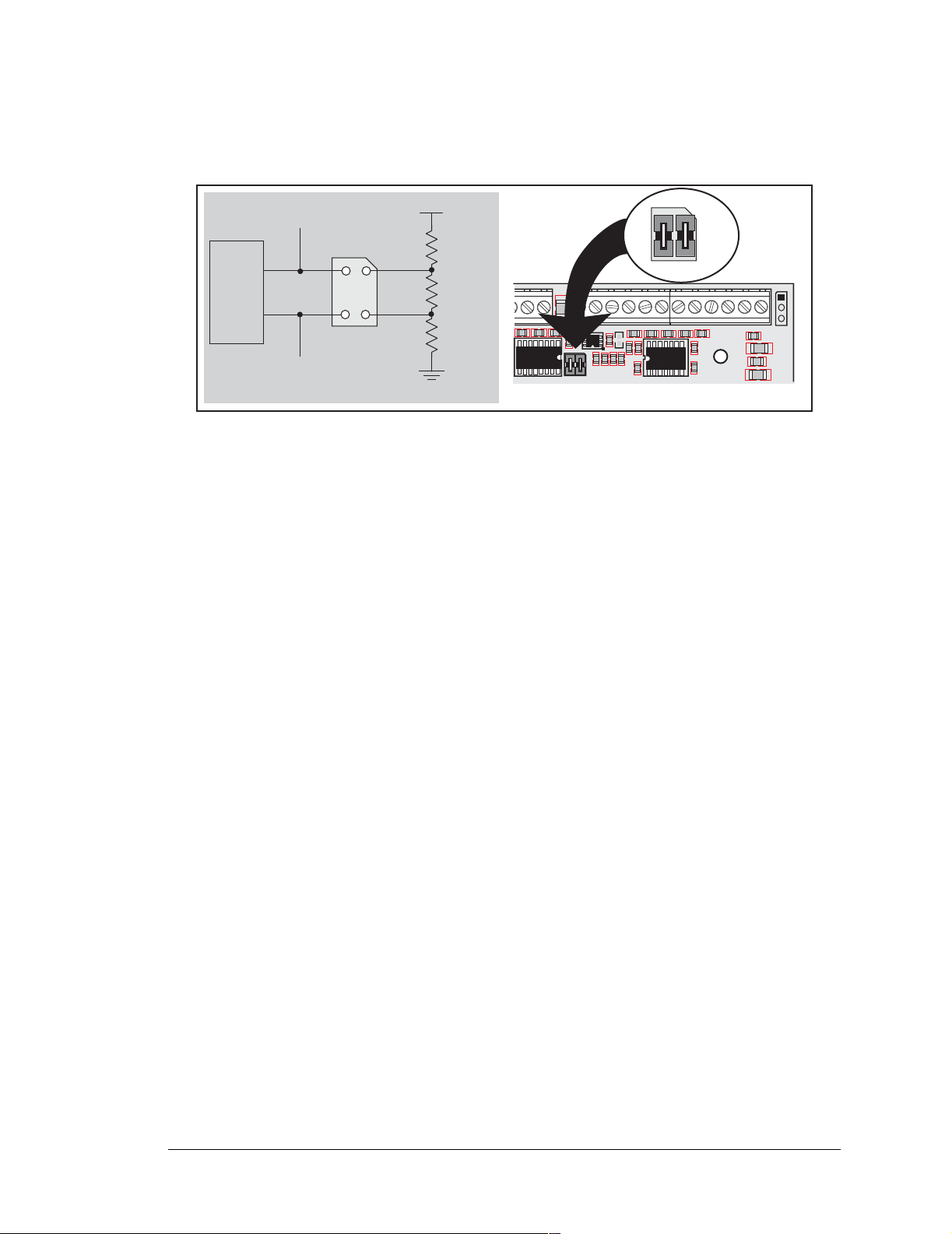
The BL2000 comes with a 220 Ω termination resistor and two 681 Ω bias resistors installed
and enabled with jumpers across pins 1–2 and 3–4 on header JP1, as shown in Figure 13.
1
U8
6
7
485+
485
2
4
JP1
1
3
bias
termi-
nation
bias
R68
681 W
R70
220 W
R77
681 W
3
JP1
2
C85
RXD1 TXD1 AGND DAC1 DAC0 ADC8 ADC7 ADC6 ADC5 ADC4 ADC3 ADC2 ADC1 ADC0
J4
J3
GND AGND
U1
AGND
C2
C3
C75
R5
U2
C8
R157
R10
R11
JP1
4
AG ND
AGND
R2
C79
C4
C11
R3R7C78
AGND
R8
R18
U3
C5
AGND
C7
Factory
Default
J12
+
C9
R14
C12
Figure 13. RS-485 Termination and Bias Resistors
The bias and termination resistors in a multidrop network should only be enabled on both
end nodes of the network. Disable the termination and bias resistors on the intervening
BL2000 units in the network by removing both jumpers from header JP1.
3.4.3 Programming Port
The BL2000 has a 10-pin programming header labeled J5. The programming port uses the
Rabbit 2000’s Serial Port A for communication. The Rabbit 2000 startup-mode pins
(SMODE0, SMODE1) are presented to the programming port so that an externally connected device can force the BL2000 to start up in an external bootstrap mode.
NOTE: Refer to the Rabbit 2000 Microprocessor User’s Manual for more information
related to the bootstrap mode.
The programming port is used to start the BL2000 in a mode where the BL2000 will
download a program from the port and then execute the program. The programming port
transmits information to and from a PC while a program is being debugged.
The BL2000 can be reset from the programming port via the /EXT_RSTIN line.
The Rabbit 2000 status pin is also presented to the programming port. The status pin is an
output that can be used to send a general digital signal.
User’s Manual 23
Page 28
3.4.4 Ethernet Port
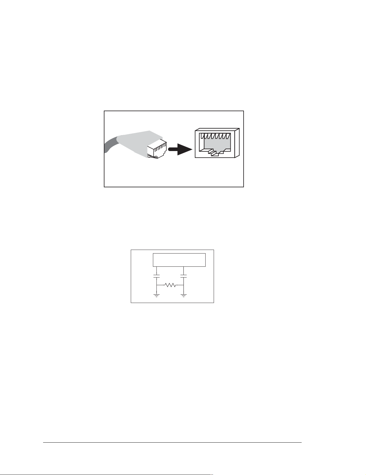
Figure 14 shows the pinout for t he Ether net po rt (J6) . Note t hat th ere are tw o stan dar ds for
numbering the pins on this connector—the convention used here, and numbering in reverse
to that shown. Regardless of the numbering convention followed, the pin positions relative
to the spring tab position (located at the bottom of the RJ-45 jack in Figure 14) are always
absolute, and the RJ-45 connector will work pr operly with off-the-shelf Ethernet cables.
ETHERNET
J6
1
1. E_Tx+
2. E_Tx
3. E_Rx+
6. E_Rx
RJ-45 Plug
RJ-45 Jack
Figure 14. RJ-45 Ethernet Port Pinout
8
RJ-45 pinouts are sometimes numbered opposite to the way shown in Figure 14.
The transformer/connector assembly ground is connected to the BL2000 printed circuit
board digital ground via a 0 Ω resistor “jumper,” R1, as shown in Figure 15.
RJ-45 Ethernet Plug
R1
Board
Ground
Chassis
Ground
Figure 15. Isolation Resistor R1
The factory default is for the 0 Ω resistor “jumper” at R1 to be installed. In high-noise
environments, it may be useful to ground the transformer/connector assembly directly
through the chassis ground. This will be especially helpful to minimize ESD and/or EMI
problems. Once you have removed the 0 Ω resistor “jumper,” R1, use a ring lug to attach
the BL2000 to the chassis ground, thereby grounding the transformer/connector assembly.
24 Wildcat (BL2000)
Page 29
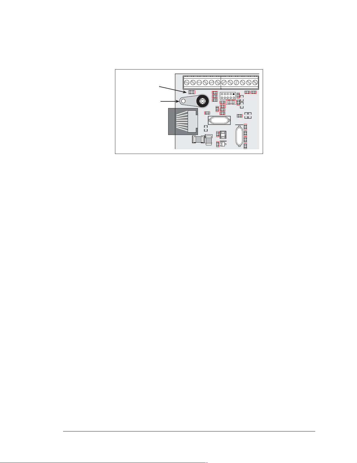
A convenient position for the ring lug has been provided at the top-left mounting screw
hole near the RJ-45 jack as shown in Figure 16.
GND RST- IN1 IN0 485- 485+ RXD2 TXD2 RXD1 TXD1+RAW +K
J1
Remove R1
Add solder lug to
connect ground
wire to chassis
Figure 16. Recommended Location for Ring Lug
J2
J6
C23
D1
GND GND
R1
GND
C20
R4
R6
C17
C24
R20
C10
R12
C16
R151
GN D
GND GND
J5
C80
R16
R19
Y3
U4
Q2
R130
R13
R15
R153
C19
Y2
C1
R9
R154
U5
R27C22
R28
C27
User’s Manual 25
Page 30
3.5 A/D Converter Inputs
The single 14-channel A/D converter used in the BL2000 has a resolution of 12 bits (models
BL2000 and BL2020) or 10 bits (models BL2010 and BL2030). Eleven of the 14 channels
are available externally, and three are used internally for the reference voltages: 4.096 V
(V
), 2.048 V (V
ref
/2), and Analog Ground. These internal voltages can be used to check
ref
the functioning of the A/D converter.
The A/D converter only measures voltages between 0 V and the applied reference voltage.
Therefore, each external input has circuitry that provides scaling and buffering. The first
four external inputs are scaled and buffered to provide the user with an input impedance of
1 MΩ and a range of -10.24 V to +10.24 V. The remaining five or seven inputs are not
buffered, but are scaled to provide inputs that can range from 0 V to +49 V.
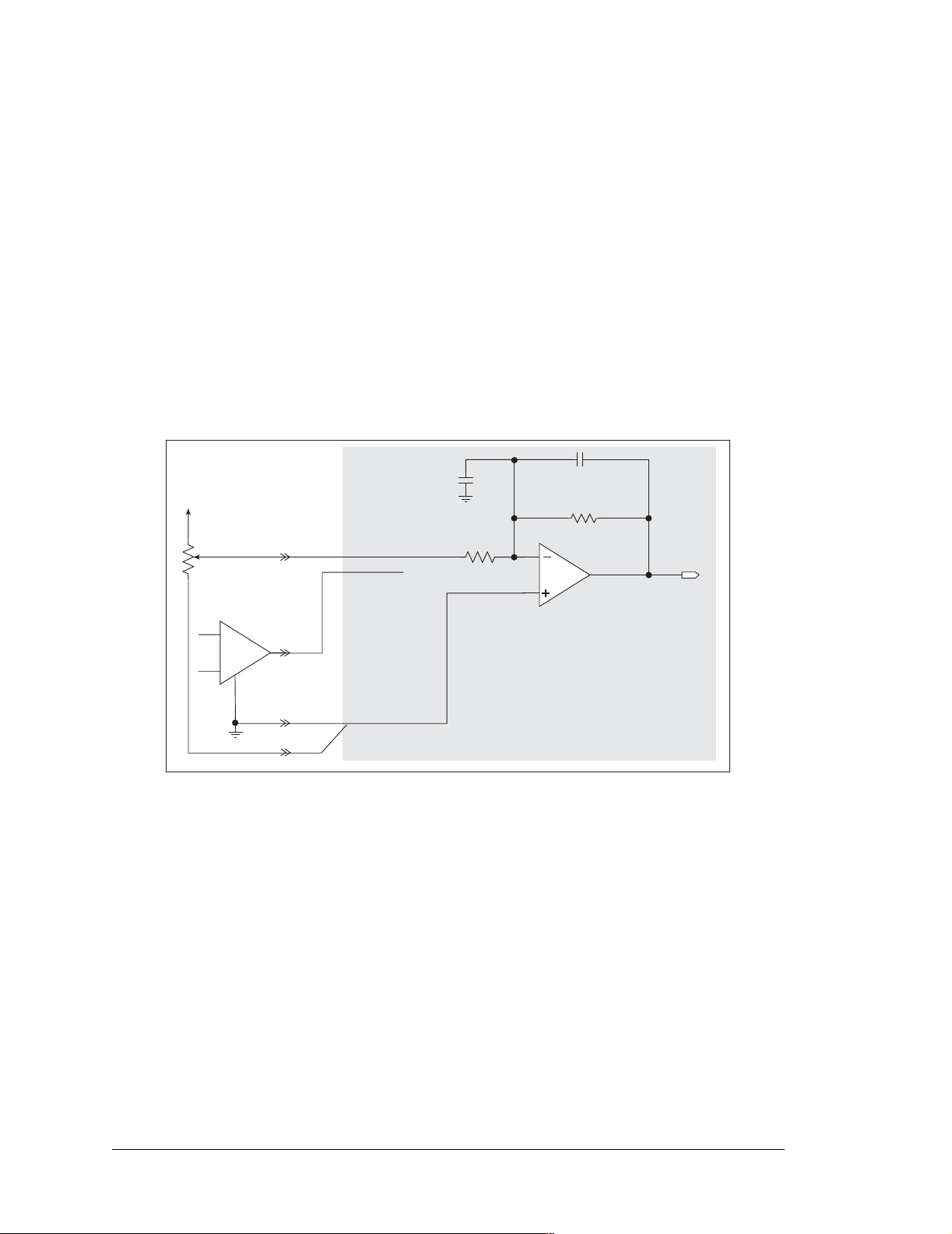
Figure 17 shows the buffered A/D converter inputs.
100 pF
200 kW
To AD C
+ V
ADC0
ADC1
100 pF
R
IN
1 MW
AGND
Figure 17. Buffered A/D Converter Inputs
The op-amp is powered from the +V supply. The 1 MΩ and 200 kΩ resistors set the gain
(scale factor), which is 0.2 in this case. This results in a dynamic input range of 4.096 V ÷
0.2 or 20.48 V. The center point of this range is set by the 1.707 V reference voltage. With
the reference set to 1.707 V, the center point is at 0 V and the input voltage can range from
-10.24 V to +10.24 V. To maintain the best accuracy, the input range should be limited to
-10.0 V to +10.0 V.
The five or seven unbuffered inputs have an impedance of 12 kΩ and a scale factor of
0.0833, which provides for an input voltage range of 0 V to 49.15 V. Accuracy is maintained over the specified voltage range from 0 V to 48 V DC.
The analog inputs can also be used as digital inputs when required. In this case a lower
quality 10-bit D/A converter can be used, and the software would assign a 1 or 0 to a voltage based on whether it is above or below a particular threshold. See the
digIn function
description for more information.
26 Wildcat (BL2000)
Page 31
3.6 D/A Converter Outputs
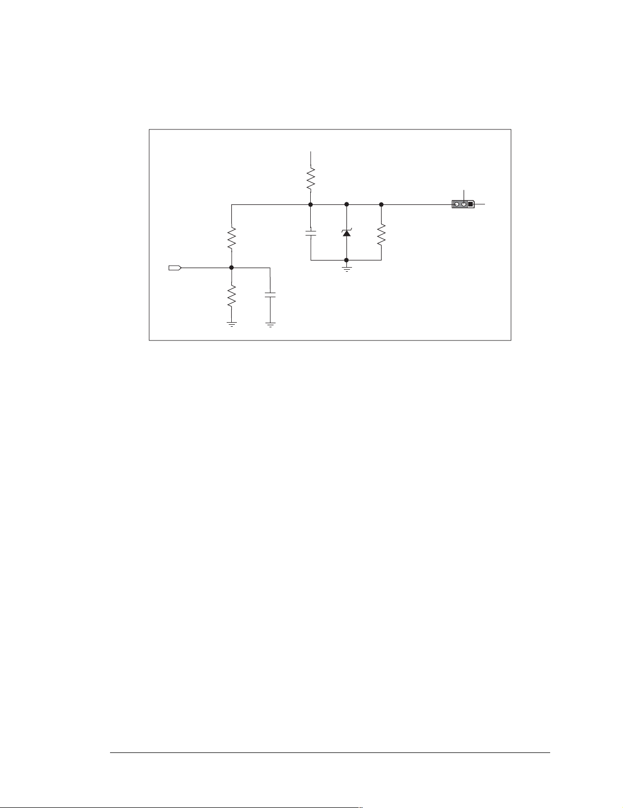
Figure 18 shows the analog voltage reference circuit.
+V
1.707_VREF
14 kW
10 kW
100 W
4.096_VREF
100 nF
ref diode
4.096 V
100 nF
Figure 18. Analog Reference Voltages
453 W
DAC_PWR
JP3
3
+ V
2
1
This circuit generates the 4.096 V reference voltage, which is used by the A/D converter
and optionally by the two D/A converters. This sets the operating range of the A/D converter and the D/A converters (0–4.096 V). To use the full accuracy of the A/D converter
and the D/A converters, this voltage must be accurate to the same degree.
Under normal operation, the 453 Ω resistor is not installed. The reference zener diode in
combination with the 100 Ω resistor form a shunt regulator. The 4.096 V reference voltage
then feeds the A/D converter, the D/A converters, and the voltage divider composed of the
10 kΩ and the 14 kΩ resistors. The voltage divider generates a second reference voltage of
1.707 V to feed the four op-amps for the buffered A/D converter inputs.
The reference voltage can be ratiometric rather than absolute. This is done by removing
the zener diode and installing the 453 Ω resistor. With this arrangement, the reference
voltages follow changes in the power supply voltages Vcc and V+, which is a filtered version of Vcc. This type of measurement circuit is preferred by some customers whose sensors are powered from the Vcc supply and hence the outputs track Vcc.
A jumper on header JP3 allows the D/A converters to be powered either from the 4.096 V
reference (factory default) or from the analog supply +V. The D/A converters use their
power source also as the reference input, so normally powering the D/A converters from
the more accurate 4.096 V reference is best. However, should a customer desire more
dynamic range (0–5 V rather than 0–4.096 V), the jumper across JP3 can be set to power
the D/A converters from +V. When powered from the +V supply, the outputs of the D/A
converters will always be ratiometric, independent of whether the zener diode is installed.
User’s Manual 27
Page 32
Only the BL2000 and the BL2020 models are stuffed with D/A converters. The D/A converters provide only a voltage output. This means that in order to maintain the maximum
accuracy of the D/A converters, only a small amount of current should be drawn from the
D/A converter output (of the order of µA).
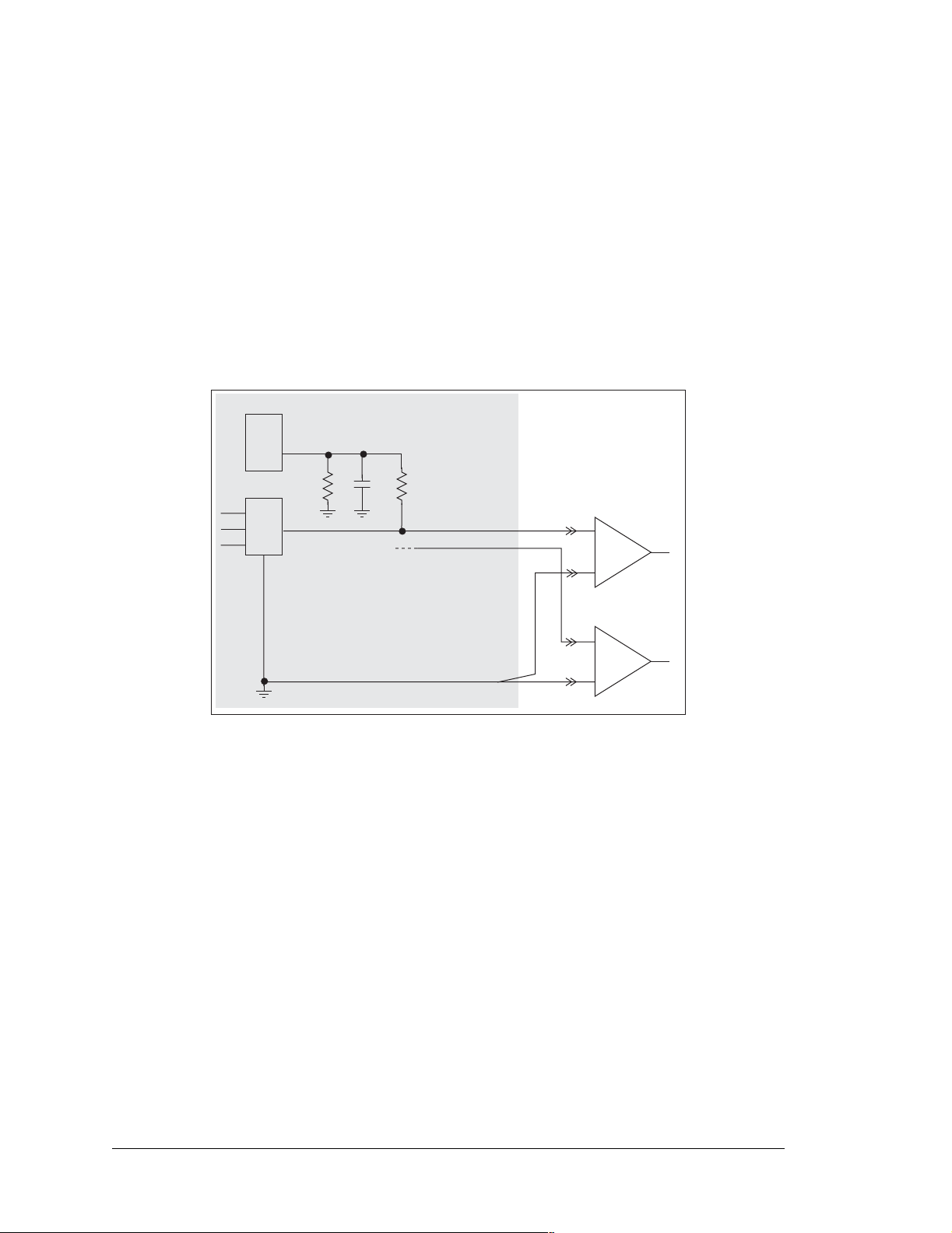
With D/A converters installed, the user has the option of using an unbuffered A/D converter input to read the output of a D/A converter or one of the two fixed voltages +V or
Vcc. The standard BL2000 configuration is for A/D converter channels 9 and 10 to monitor D/A converter channels 0 and 1 respectively.
Figure 19 shows the D/A converter outputs with buffer amplifiers, which may be used to
increase the D/A converter output voltage range to 0 V to +10 V.
ADC
AIN9
1 kW
10 nF
DAC0
11 kW
DAC0
DAC1
+
AGND
Figure 19. D/A Converter Outputs
+
28 Wildcat (BL2000)
Page 33
3.7 Memory
Section A.3, “Jumper Configurations,” shows where the 0 Ω surface-mounted “jumpers”
described in this section are found.
3.7.1 SRAM
The BL2000 is designed to accept 128K to 512K of SRAM packaged in an SOIC case.
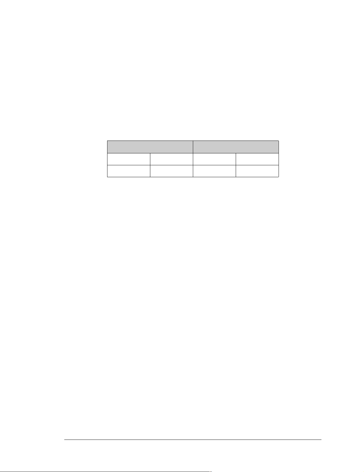
The standard models come with 128K of SRAM. Table 3 lists the jumper settings for the
jumpers used to set the SRAM size. The “jumpers” are 0 Ω surface-mounted resistors.
Table 3. Memory Jumper Selections
SRAM (JP5) Flash Memory (JP4)
1–2 128K 1–2 128K/256K
2–3 512K 2–3 512K
3.7.2 Flash M emory
The BL2000 is also designed to accept 128K to 512K of flash memory packaged in a
TSOP case.
The BL2000 comes with one 256K flash memory. Table 3 lists the jumper settings for the
jumpers used to set the SRAM size. The “jumpers” are 0 Ω surface-mounted resistors.
NOTE: Z-Wor ld rec ommends that any cust omer applications should not be constrain ed
by the sector size of the flash memory since it may be necessary to change the sector
size in the future.
A Flash Memory Bank Select jumper configuration option exists at JP2 with 0 Ω surfacemounted resistors. This option, used in conjunction with some configuration macros,
allows Dynamic C to compile two different co-resident programs for the upper and lower
halves of the 256K flash in such a way that both programs start at logical address 0000.
This is useful for applications that require a resident download manager and a separate
downloaded program. See Technical Note 218, Implementing a Serial Download Man-
ager for a 256K Flash, for details.
User’s Manual 29
Page 34
3.8 Programming Cable
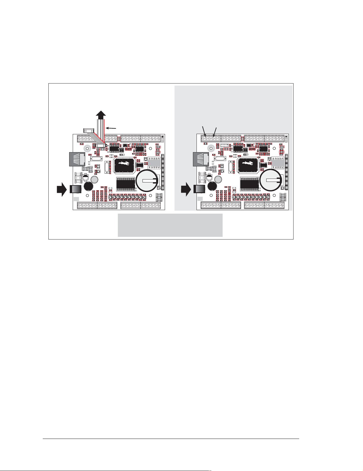
The BL2000 is automatically in Program Mode when the programming cable is attached,
and is automatically in Run Mode when no programming cable is attached. See Figure 20.
Power
Program Mode
To
PC COM port
Programming Cable
J5
R16
R19
U4
Q2
C80
Y3
C31
R33
GND GND
R13
C1
R9
R130
R15
R153
C19
U5
Y2
C27
R32
R34
R35
R40
R31
D3
C36
C35
R39
R38
R52
C41R53
C40
R57
R56
R60
R61
C43
GNDGNDGNDGND
Colored edge
C85
J4
J3
AGND
C2
C3
U2
C8
R157
JP1
U1
R154
C18
JP2
65
R27C22
90
R28
15
R41
R42
R43 R44
D4
D7 D8 D9
D5
D6
C47
C46
C44
C45
GND
AGND
AGND
C75
R5
C79
R2
R7
C4
R10
R11
C11
R17
C13
C76
R152
40
C26
U6
R47
R45
R46
D10
C50
C49C48
GND
GND
DIAG
GND RST- IN1 IN0 485- 485+ RXD2 TXD2 RXD1 TXD1 AGND DAC1 DAC0ADC8 ADC7 ADC6ADC5 ADC4 ADC3ADC2 ADC1 ADC0+RAW +K
J1
J2
GND
GN D
GND GND
R4
R6
R1
PROG
R12
C10
R20
C20
C16
C17
C24
J6
TVS1
J7
POWER IN
J8
J10
R151
C23
D1
C25
R30
C28
C29
+
D2
14
+
L1
23
C34
C33
R36
R37
R51
C38R50
C39
R55
R54
R59
R58
GND
GN D
IN3IN2 IN4 IN5 IN6 IN7 IN8 IN9 IN10 OUT8 OUT9 GND GNDOUT0 OUT1OUT2 OUT3 OUT4 OUT5 OUT6OUT7 NC
RESET BL2000 when changing mode:
Short out RESET pin on header J2 to ground,
Remove, then reapply power
after removing or attaching programming cable.
R22
C21
C32
AG ND
C78
R23
C14
R24
1432
R29
Q3
Q5
Battery
R48
D11 D12
C51
GN D
AGND
AGND
R3
C77
Y1
D
J12
C5
C7
+
R8
C9
U3
R14
R18
C12
C15
DS1
R21
Q1
R25
R26
G
R49
C52
GND
56
Q4
S
NO
COM
PWRLNKACTOUT 0OUT 1OUT 2OUT 3BAD
1
10
DS4DS3DS2
K1
DS5
BT1
DS6
+
+
Q6
GND
GND
Power
DS7
DS8
C37
C42
J11
J9
GND
GND RST- IN1 IN0 485- 485+ RXD2 TXD2 RXD1 TXD1 AGND DAC1 DAC0ADC8 ADC7 ADC6ADC5 ADC4 ADC3ADC2 ADC1 ADC0+RAW +K
J1
J2
GND GND
R1
J6
C23
D1
TVS1
+
D2
14
23
J7
POWER IN
GND
J8
J10
IN3IN2 IN4 IN5 IN6 IN7 IN8 IN9 IN10 OUT8 OUT9 GND GNDOUT0 OUT1OUT2 OUT3 OUT4 OUT5 OUT6OUT7 NC
OR
Figure 20. BL2000 Program Mode and Run Mode Set-Up
RESET
PIN
GND
R4
R6
R12
C10
R20
C20
C16
C17
C24
R151
C25
C28
L1
+
C33
R36
C38R50
R54
R58
Run Mode
GN D
GND GND
J5
R13
C1
R9
C80
R130
R16
R15
R19
R153
R154
C18
C19
Y3
U5
Y2
R27C22
U4
R28
C27
Q2
R30
C29
R32
R34
R35
R40
C31
R31
D3
R33
C34
C36
C35
R37
R39
R38
R41
D4
R51
R52
C39
C41R53
C40
R57
R55
R56
R60
R59
R61
C44
C43
GNDGNDGNDGND
GN D
GND
C85
J4
J3
AGND
AGND
AGND
C2
C3
C75
R5
C79
U2
C8
R7
C4
R157
R10
R11
C11
JP1
R17
U1
C13
JP2
C76
R152
65
90
40
15
U6
R45
R42
R43 R44
R46
D7 D8 D9
D5
D6
C47
C46
C49C48
C45
GND
GND
AGND
AG ND
AGND
R2
C78
R3
R23
C14
C77
R22
C21
R24
Y1
1432
R29
C26
D
Q3
Battery
Q5
C32
R48
R47
D11 D12
D10
C51
C50
GN D
J12
C5
C7
+
R8
C9
U3
R14
R18
C12
C15
DS1
R21
Q1
R25
R26
G
R49
C52
GND
56
Q4
S
NO
PWRLNKACTOUT 0OUT 1OUT 2OUT 3BAD
1
10
DS4DS3DS2
K1
DS5
BT1
DS6
+
DS7
+
DS8
Q6
C37
C42
GND
GND
J11
J9
COM
3.8.1 Detailed Instructions: Changing from Program Mode to Run Mode
1. Disconnect the programming cable from header J5 of the BL2000.
2. Reset the BL2000 by unplugging the AC adapter, then plugging it back in, or by
momentarily connecting the reset pin on screw terminal header J2 to ground.
The BL2000 is now ready to operate in the Run Mode.
3.8.2 Detailed Instructions: Changing from Run Mode to Program Mode
1. Attach the programming cable to header J5 of the BL2000.
2. Reset the BL2000 by unplugging the AC adapter, then plugging it back in, or by
momentarily connecting the reset pin on screw terminal header J2 to ground. Alternatively, you may press <Ctrl-Y> on your PC if Dynamic C is running.
The BL2000 is now ready to operate in the Program Mode.
30 Wildcat (BL2000)
Page 35

3.9 Other Hardware
3.9.1 External Interrupts
BL2000 boards with a Rabbit 2000 microprocessor labeled IQ3T or higher have external
interrupts available on digital inputs IN2 and IN3. Older BL2000 boards (Rabbit 2000
microprocessors labeled IQ2T) have one external interrupt available—see T echnical Note
TN301, Rabbit 2000 Microprocessor Interrupt Problem, for further information on how
to use this interrupt on the older boards.
3.9.2 Clock Doubler
The BL2000 takes advantage of the Rabbit 2000 microprocessor’s internal clock doubler.
A built-in clock doubler allows half-frequency crystals to be used to reduce radiated emissions. The 22.1 MHz frequency is generated using an 11.0592 MHz crystal. The clock
doubler is disabled automatically in the BIOS for crystals with a frequency above
12.9 MHz.
The clock doubler may be disabled if 22.1 MHz clock speeds are not required. Disabling
the Rabbit 2000 microprocessor’s internal clock doubler will reduce power consumption
and further reduce radiated emissions. The clock doubler is disabled with a simple change
to the BIOS as described below.
1. Open the BIOS source code file, RABBITBIOS.C in the BIOS directory.
2. Change the line
#define CLOCK_DOUBLED 1 // set to 1 to double clock if
// Rabbit 2000: crystal <= 12.9024 MHz,
// Rabbit 3000: crystal <= 26.7264 MHz,
// or to 0 to always disable clock doubler
to read as follows.
#define CLOCK_DOUBLED 0
3. Save the change using File > Save.
3.9.3 Spectrum Spreader
BL2000 boards that carry the CE mark have a Rabbit 2000 microprocessor that features a
spectrum spreader, which helps to mitigate EMI problems. By default, the spectrum
spreader is on automatically for BL2000 boards that carry the CE mark when used with
Dynamic C 7.32 or later versions, but the spectrum spreader may also be turned off or set
to a stronger setting. The means for doing so is through a simple change to the following
BIOS line in a way that is similar to the clock doubler described above.
#define ENABLE_SPREADER 1 // Set to 0 to disable spectrum spreader
// 1 to enable normal spreading, or
// 2 to enable strong spreading.
NOTE: The strong spectrum-spreading setting is unnecessary for the BL2000.
There is no spectrum spreader functionality for BL2000 boards that do not carry the CE
mark or when using any BL2000 with a version of Dynamic C prior to 7.30.
User’s Manual 31
Page 36

32 Wildcat (BL2000)
Page 37

4. SOFTWARE
Dynamic C is an integrated development system for writing
embedded software. It runs on an IBM-compatible PC and is
designed for use with Z-World single-board computers and other
devices based on the Rabbit microprocessor.
Chapter 4 provides the libraries, function calls, and sample programs related to the BL2000.
4.1 Running Dynamic C
You have a choice of doing your software development in the flash memory or in the static
RAM included on the BL2000. The advantage of working in RAM is to save wear on the
flash memory, which is limited to about 100,000 write cycles.
NOTE: An application can be developed in RAM, but cannot run standa lone from RAM
after the programming ca ble is disconn ected. S tandalone ap plications can on ly run from
flash memory.
The disadvantage of using flash memory for debug is that interrupts must be disabled for
approximately 5 ms whenever a break point is set in the program. This can crash fast interrupt routines that are running while you stop at a break point or single-step the program.
Flash memory or RAM is selected on the Options > Compiler menu.
Dynamic C provides a number of debugging features. You can single-step your program,
either in C, statement by statement, or in assembly language, instruction by instruction.
You can set break points, where the program will stop, on any statement. Y ou can evaluate
watch expressions. A watch expression is any C expression that can be evaluated in the
context of the program. If the program is at a break point, a watch expression
expression using local or external variables.
can view any
User’s Manual 33
Page 38

4.1.1 Upgrading Dynamic C
4.1.1.1 Patches and Bug Fixes
Dynamic C patches that focus on bug fixes are available from time to time. C heck the Web
site
• www.zworld.com/support/
for the latest patches, workarounds, and bug fixes.
The default installation of a patch or bug fix is to install the file in a directory (folder) dif-
ferent from that of the original Dynamic C installation. Z-World recommends using a different directory so that you can verify the operation of the patch without overwriting the
existing Dynamic C installation. If you have made any changes to the BIOS or to libraries,
or if you have programs in the old directory (folder), make these same changes to the
BIOS or libraries in the new directory containing the patch. Do not simply copy over an
entire file since you may overwrite a bug fix; of course, you may copy over any programs
you have written. Once you are sure the new patch works entirely to your satisfaction, you
may retire the existing installation, but keep it available to handle legacy applications.
4.1.1.2 Upgrades
Dynamic C installations are designed for use with the board they are included with, and
are included at no charge as part of our low-cost kits. Dynamic C is a complete software
development system, but does not include all the Dynamic C features. Z-W orld also offers
add-on Dynamic C modules containing the popular µC/OS-II real-time operating system,
as well as PPP, Advanced Encryption Standard (AES), and other select libraries. In addition to the Web-based technical support included at no extra charge, a one-year telephonebased technical support module is also available for purchase.
34 Wildcat (BL2000)
Page 39

4.2 Sample Programs
Sample programs are provided in the Dynamic C SAMPLES folder. The sample program
PONG.C demonstrates the output to the STDIO window. The various directories in the
SAMPLES folder contain specific sample programs that illustrate the use of the correspond-
ing Dynamic C libraries.
SAMPLES\BL2000 folder provides sample programs specific to the BL2000. Each
The
sample program has comments that describe the purpose and function of the program. Follow the instructions at the beginning of the sample program.
T o r un a s ample progra m, op en it with the File menu (if it is not st ill o pen) , comp ile it using
the Compile menu, and then run it by selecting Run in the Run menu. The BL2000 must
be in Program mode (see Section 3.8, “Programming Cab le,”) an d must be connected to a
PC using the programming cable as described in Section 2.1, “BL2000 Connections.”
More complete information on Dynamic C is provided in the Dynamic C User’s Manual.
4.2.1 General BL2000 Sample Programs
• BOARD_ID.C—This program is used to identify the model of BL2000 being used, and
displays that information in the STDIO window.
• COUNTLEDS.C—This program will count from 0 to 31 in binary, using the four general-purpose LEDs, DS4–DS7, and the Processor Bad LED, DS8. The LEDs are used
in reverse logical order to min imize the cyc ling of the rel ay, which is slaved to the same
output as DS4.
• LEDS_4.C—This program creates four “devices” (lights), and four buttons to toggle
them. Users can view the devices with their Web browser, and change the status of the
lights. If the Demonstration Board is connected to the BL2000, the lights on the Demonstration Board will match the ones on the Web page. See Appendix D for hookup
instructions for the Demonstration Board.
4.2.2 Digital I/O
The following sample programs are found in the IO subdirectory in SAMPLES/BL2000.
• ANADIGIN.C—Demonstrates using the A/D converter channels as digital inputs. You
will be able to see an input channel toggle HIGH and LOW when pressing the pushbuttons on the Demonstration Board. See Appendix D for hookup instructions for the
Demonstration Board.
• DIGIN.C—Demonstrates the use of the digital inputs. Using the Demonstration Board,
you can see an input channel toggle from HIGH to LOW when pressing a pushbutton
on the Demonstration Board. See Appendix D for hookup instructions for the Demonstration Board.
• DIGOUT.C—Demonstrates the use of the high-current outputs. Using the Demonstration Board, you can see an LED toggle on/off via a high-current output. See Appendix
D for hookup instructions for the Demonstration Board.
• LED.C—Demonstrates how to toggle the output LEDs on the BL2000 on/off.
User’s Manual 35
Page 40

• PWM.C—Demonstrates the use of Timer B to generate a PWM signal on digital output
OUT8. The program generates a 42 Hz PWM signal with the duty cycle adjustable
from 1 to 99%.
RELAY.C—Demonstrates how to control the relay on the BL2000.
•
4.2.3 Serial Co mmunication
The following sample programs are found in the RS232 subdirectory in SAMPLES/BL2000.
• PUTS.C—Transmits and then receives an ASCII string on Serial Ports B and C. It also
displays the serial data received from both ports in the STDIO window.
• RELAYCHR.C—This program echoes characters over Serial Port B to Serial Port C. It
must be run with a serial utility such as Hyperterminal.
The following sample programs are found in the RS485 subdirectory in SAMPLES/BL2000.
• MASTER.C—This program demonstrates a simple RS-485 transmission of lower case
letters to a slave BL2000. The slave will send back converted upper case letters back to
the master BL2000 and display them in the STDIO window. Use SLAVE.C to program
the slave BL2000.
• SLAVE.C—This program demonstrates a simple RS-485 transmission of lower case
letters to a slave BL2000. The slave will send back converted upper case letters back to
the master BL2000 and display them in the STDIO window . Use MASTER.C to program
the master BL2000.
4.2.4 A/D Converter Inputs
The following sample programs are found in the ADC subdirectory in SAMPLES/BL2000.
• AD_CALIB.C—Demonstrates how to recalibrate an A/D converter channel using two
known voltages to generate two coefficients, gain and offset, which are rewritten into
the user block data area. The voltage that is being monitored is displayed continuously.
Note that this sample program will overwri te the c alibra tion cons tant s se t at t he fa c tory.
• AD1.C—Demonstrates how to access the A/D internal test voltages in both the
TLC2543 and TLC1543 A/D converter chips. The program reads the A/D internal voltages and then uses the STDIO window to display the RAW data.
• AD2.C—Demonstrates how to access the A/D channels using the anaInVolt function .
The program uses the STDIO window to display the voltage that is being monitored.
• AD3.C—Demonstrates how to access the A/D converter channels with the low-level
A/D driver. The program uses the STDIO window to display the voltage that is being
monitored on all the A/D channels using the low-level A/D driver.
• AD4.C—Demonstrates how to use the A/D converter channels with the low-level A/D
driver. The program uses the STDIO window to display the voltage (average of 10 samples) that is being monitored on all the A/D converter channels using the low-level A/D
driver.
36 Wildcat (BL2000)
Page 41

4.2.5 D/A Converter Outputs
The following sample programs are found in the DAC subdirectory in SAMPLES/BL2000.
DACAL.C—This program demonstrates how to recalibrate an D/A converter channel
•
using two known voltages, and defines the two coefficients, gain and offset, that will be
rewritten into the D/A converter's EEPROM simulated in flash memory. Note that this
sample program will overwrite the calibration constants set at the factory.
• DAOUT1.C—This program outputs a voltage that can be read with a voltmeter. The output voltage is computed using the calibration constants that are read from the EEPROM
simulated in flash memory.
• DAOUT2.C—This program demonstrates the use of both the D/A and the A/D converters. The user selects both the D/A converter and A/D channel to be used, then sets the
D/A converter output voltage to be read by the A/D channel. All activity will be displayed in the STDIO window.
4.2.6 TCP/IP Sample Programs
TCP/IP sample programs are described in Chapter 5.
User’s Manual 37
Page 42

4.3 BL2000 Libraries
Two library directories are used to develop applications for the BL2000.
•
BL2000-—libraries associated with features specific to the BL2000.
• TCPIP—libraries specific to using TCP/IP functions on the BL2000.
Other generic functions applicable to all devices based on the Rabbit 2000 microprocessor
are described in the Dynamic C Function Reference Manual.
38 Wildcat (BL2000)
Page 43

4.4 BL2000 Function APIs
4.4.1 Board Initialization
void brdInit (void);
Call this function at the beginning of your program. This function initializes the system I/O ports and
loads all the A/D and DAC calibration constants from flash memory into SRAM for use by your program.
The ports are initialized as follows:
Port I/O Function
PA0 Output OUT0/RELAY/LED_DS4
PA1 Output OUT1/LED_DS5
PA2 Output OUT2/LED_DS6
PA3 Output OUT3/LED_DS7
PA4 Output OUT4
PA5 Output OUT5
PA6 Output OUT6
PA7 Output OUT7
PB0 Input IN6 N/A
Output Function
State
High-Current Driver
Off
High-Current Driver
Off
High-Current Driver
Off
High-Current Driver
Off
High-Current Driver
Off
High-Current Driver
Off
High-Current Driver
Off
High-Current Driver
Off
PB1 Input CLKA N/A
PB2 Input IN7 N/A
PB3 Input IN8 N/A
PB4 Input IN9 N/A
PB5 Input IN10 N/A
PB6 Output RS485_EN Off
PB7 Output UPGOOD Bad Indicator Off
PC0 Output TXD RS-485 Inactive high
PC1 Input RXD RS-485 N/A
User’s Manual 39
Page 44

Port I/O Function
Output Function
State
PC2 Output RTS/TXC RS-232 Inactive high
PC3 Input CTS/RXC RS-232 N/A
PC4 Output TXB RS-232 Inactive high
PC5 Input RXB RS-232 N/A
PC6 Output TXA Programmi ng Po rt Inactive high
PC7 Input RXA Programming Port N/A
PD0 Output DAC-ADC_SK On
PD1 Output DAC-ADC_SDI On
PD2 Input RTL-ADC_SDO N/A
PD3 Input RTL_SK
N/A
PD4 Output RTL_SDI On
PD5 Output DAC0_CS Inactive high
PD6 Output DAC1_CS Inactive high
PD7 Output ADC_CS Inactive high
PE0 Output OUT8
PE1 Output OUT9
High-Current Driver
Off
High-Current Driver
Off
PE2 Input IN0 N/A
PE3 Input IN1 N/A
PE4 Input IN2 N/A
PE5 Input IN3 N/A
PE6 Input IN4 N/A
PE7 Input IN5 N/A
* PD3 is an output (and is on) for the BL2020 and the BL2030.
*
SEE ALSO
digOut, digIn, serMode
40 Wildcat (BL2000)
Page 45

4.4.2 Digital I/O
int digIn(int channel);
Reads the state of an input channel:
IN0–IN10—standard digital inputs, ± 36 V DC
IN11–IN14—pseudo digital inputs using A/D converter inputs ADC0–ADC3, ± 10 V DC
IN15–IN19—pseudo digital inputs using A/D converter inputs ADC4–ADC8, 0 V to 48 V DC
IN20–IN21—pseudo digital inputs using A/D converter inputs DAC0–DAC1, 0 V to 48 V DC
(BL2010 and BL2030)
The threshold is fixed at 2.40 V for channels IN0–IN10. Anything below 2.40 V is a logic 0, and anything higher than or equal to 2.40 V is a logic 1.
The default threshold for channels IN11–IN21 is also set to 2.40 V. The threshold for these channels may
be changed by adding the following two lines to your program.
#undef THRESHOLD
#define THRESHOLD xx.xx
where xx.xx is the desired threshold voltage. Anything below the threshold value is a logic 0, and anything higher than or equal to the threshold value is a logic 1.
PARAMETER
channel is the input channel number (0–21)
RETURN VALUE
The state of the input (0 or 1).
SEE ALSO
brdInit, digOut
void digOut(int channel, int value);
Sets the state of a digital output (OUT0–OUT9).
The default setting for the function is for current-sinking outputs. To change from sinking to sourcing
outputs, add the following two lines at the beginning of your program.
#undef OUTPUT_DRIVE
#define OUTPUT_DRIVE SOURCING
The relay is driven by PA0, which is the same Rabbit 2000 parallel port th at drives OU T0 and LED D S4.
OUT0 therefore works in parallel with the relay output. Z-World therefore recommends that you do not
use OUT0 for a digital output when you are using the relay.
PARAMETERS
channel is the output channel number (0–9).
value is the output value (0 or 1).
SEE ALSO
brdInit, digIn
User’s Manual 41
Page 46
4.4.3 Serial Co mmunication
Library files included with Dynamic C provide a full range of serial communications support. The RS232.LIB library provides a set of circular-buffer-based serial functions. The
PACKET.LIB library provides packet-based serial functions where packets can be delim-
ited by the 9th bit, by transmission gaps, or with user-defined special characters. Both
libraries provide blocking functions, which do not return until they are finished transmitting or receiving, and nonblocking functions, which must be called repeatedly until they
are finished. For more information, see the Dynamic C Function Reference Manual and
Technical Note 213, Rabbit 2000 Serial Port Software.
The following function calls are specific to the BL2000.
int serMode(int mode);
User interface to set up BL2000 serial communication lines. Call this function after serXOpen().
If Mode 1 is selected, CTS/RTS flow control is exercised using the
serCflowcontrolOff functions from the RS232.LIB library.
PARAMETER
mode is the defined serial port configuration.
Serial Port
Mode
B C D
0 RS-232, 3-wire RS-232, 3-wire RS-485
1 RS-232, 5-wire CTS/RTS RS-485
RETURN VALUE
0 if valid mode, 1 if not.
SEE ALSO
ser485Tx, ser485Rx
void ser485Tx(void);
Sets (high) pin 3 (DE) to enable Tx.
serCflowcontrolOn and
SEE ALSO
serMode, ser485Rx
void ser485Rx(void);
Resets (low) pin 3 (DE) to disable Tx.
SEE ALSO
serMode, ser485Tx,
42 Wildcat (BL2000)
serCflowcontrolOn, serCflowcontrolOff
Page 47

4.4.4 Relay and LED Outputs
void relayOut(int relay, int value);
Sets the state of a relay.
The relay is driven by PA0, which is the same Rabbit 2000 parallel port th at drives OU T0 and LED D S4.
OUT0 therefore works in parallel with the relay output. Z-World therefore recommends that you do not
use OUT0 for a digital output when you are using the relay.
PARAMETERS
relay is the relay to control, 0 = Relay 0.
value is the value used to connect the relay common contact to one of the following contacts:
0 = relay common connected to relay normally closed contact
1 = relay common connected to relay normally open contact
SEE ALSO
brdInit
void ledOut(int led, int value);
LED ON/OFF control.
The relay is driven by PA0, which is the same Rabbit 2000 parallel port that drives OUT0 and LED0.
OUT0 therefore works in parallel with the relay output. Z-World therefore recommends that you do not
use OUT0 for a digital output when y ou are u sing the relay. The relay and OUT0 are also turned on when
LED0 is turned on.
PARAMETERS
led is the LED to control:
0 = OUT0 LED
1 = OUT1 LED
2 = OUT2 LED
3 = OUT3 LED
4 = BAD indicator
value is the value used to control the LED:
0 = OFF
1 = ON
SEE ALSO
brdInit
User’s Manual 43
Page 48

4.4.5 A/D Converter Inputs
void anaInCalib(int channel, int value1,
float volts1, int value2, float volts2);
Calibrates the response of the A/D converter channel as a linear function using the two conversi on poi nts
provided. Gain and offset constants are calculated and placed into global table
PARAMETERS
channel is the A/D converter input channel (0–10).
value1 is the first A/D converter channel value.
volts1 is the voltage corresponding to the first A/D converter channel value.
value2 is the second A/D converter channel value.
volts2 is the voltage corresponding to the second A/D converter channel value.
RETURN VALUE
0 if successful.
-1 if not able to make calibration constants.
SEE ALSO
anaIn, anaInVolts, brdInit
_adcInCalib.
int _anaIn(unsigned char cmd, char len);
Reads the voltage of an analog input channel by serially clocking out an 8-bit command to the A/D converter device of the following formats:
TLC2543 commands
D7–D4
Channel 0 - 10
Channel 11 = (V
Channel 12 = V
Channel 13 = V
Channel 14 = software powerdown
D3-D2
Output data length:
01—8 bits
00—12 bits (normally used as default)
11—16 bits (not supported by driver)
D1
Output data format
0—MSB first
1—LSB first (not supported by driver)
D0
Mode of operation
0—Unipolar (normally used as default)
1—Bipolar
ref+
refref+
- V
ref-
)/2
44 Wildcat (BL2000)
Page 49

TLC1543 commands (the TLC1543 is a 10-bit A/D converter)
D7–D4
Channel 0 - 10
Channel 11 = (Vref+ - Vref-)/2
Channel 12 = VrefChannel 13 = Vref+
(No software power-down mode available)
D3–D0
No specific values assigned.
PARAMETERS
cmd is the A/D converter input channel (0–10) to read.
len is the output data length:
0 = 12-bit mode (BL2000/BL2020 only)
1 = 8-bit mode (BL2000/BL2020 only)
2 = 10-bit mode (BL2010/BL2030 only)
RETURN VALUE
A value corresponding to the voltage on the A/D converter input channel, which will be:
0–4095 for 12-bit A/D conversio ns
0–1023 for 10-bit A/D conversio ns
0–255 for 8-bit A/D conversions
SEE ALSO
anaIn, anaInVolts, brdInit, samples/bl2000/adc/AD3.C
int anaIn(unsigned int channel);
Reads the state of an A/D converter input channel.
PARAMETER
channel is the A/D converter input channel (0–10) to read.
RETURN VALUE
A value corresponding to the voltage on the analog input channel, which will be:
0–4095 for 12-bit A/D conversio ns (BL200 0,B L202 0)
0–1023 for 10-bit A/D conversio ns (BL201 0,B L203 0).
SEE ALSO
anaInVolts, anaInCalib, _anaIn, brdInit
User’s Manual 45
Page 50

float anaInVolts(unsigned int channel);
Reads the state of an A/D converter input channel and uses the previously set calibration constants to
convert it to volts.
PARAMETER
channel is the A/D converter input channel (0–10).
RETURN VALUE
A voltage value corresponding to the voltage on the analog input channel.
SEE ALSO
anaIn, anaInCalib, brdInit
int anaInEERd(unsigned int channel);
Reads the calibration constants, gain, and offset from the simulated EEPROM in flash memory (located
in reserved user block memory area 0x1C00–0x1FFF).
PARAMETER
channel is the A/D converter input channel (0–10).
RETURN VALUE
0 if successful.
-1 if address or range is invalid.
SEE ALSO
anaInEEWr, brdInit
int anaInEEWr(unsigned int channel);
Writes the calibration constants, gain, and offset to the simulated EEPROM in flash memory (located in
reserved user block memory area 0x1C00–0x1FFF).
PARAMETER
channel is the A/D converter input channel (0–10).
RETURN VALUE
0 if successful.
-1 if address or range is invalid.
SEE ALSO
anaInEERd, brdInit
The address range of the user block memory area where the calibration constants are
stored may be determined using
readUserBlock( _adcCalib, ADC_CALIB_ADDR, sizeof( _adcCalib ) );
where _adcCalib and ADC_CALIB_ADDR are macros defined in the BL20XX.LIB
library.
46 Wildcat (BL2000)
Page 51

4.4.6 D/A Converter Outputs
The functions in this section apply only to the BL2000 and the BL2020 models.
int anaOutCalib(int channel, int value1,
float volts1, int value2, float volts2);
Calibrates the response of the D/A converter channel desired as a linear function using the two conversion points provided. Gain and offset constants are calculated and placed into global table _dacCalib.
PARAMETERS
channel is the D/A converter output channel (0 or 1).
value1 is the first D/A converter value.
volts1 is the voltage corresponding to the first D/A converter value.
value2 is the second D/A converter value.
volts2 is the voltage corresponding to the second D/A converter value.
RETURN VALUE
0 if sucessful .
-1 if not able to make calibration constants.
SEE ALSO
anaOut, anaOutVolts, brdInit
User’s Manual 47
Page 52
void anaOut(unsigned int channel, unsigned int
modecount);
Sets the voltage of a D/A converter output channel by serially clocking in 16 bits to a D/A converter
using the following format:
D15–D14
Doesn’t matter.
D13–D12
Mode of operation
00—Normal Operation
01—Software Powerdown, 1 kΩ to GND
10—Software Powerdown, 100 kΩ to GND
11—Software Powerdown, three-state
D11–D0
Data bits, MSB–LSB (0–4095)
PARAMETERS
channel is the D/A converter output channel to write (0 or 1).
modecount is a value corresponding to the voltage on the D/A converter output and/or setting the
mode of operation
:
Operation
Mode
0 Normal Mode 0–4095
1 Software Powerdown, 1 kΩ to GND 0x1000
2 Softw are Powerdow n, 100 kΩ to GND 0x2000
3 Software Powerdown, three-state 0x3000
RETURN VALUE
None
SEE ALSO
anaOutVolts, anaOutCalib, brdInit
Description modecount Value
48 Wildcat (BL2000)
Page 53

void anaOutVolts(unsigned int channel,
float voltage);
Sets the voltage of a D/A converter output channel by using the previously set calibration constants to
calculate the correct data values.
PARAMETERS
channel is the D/A converter output channel (0 or 1).
voltage is the voltage desired on the output channel.
SEE ALSO
anaOut, anaOutCalib, brdInit
int anaOutEERd(unsigned int channel);
Reads the calibration constants, gain, and offset from the simulated EEPROM in flash memory (located
in reserved user block memory area 0x1C00–0x1FFF).
PARAMETER
channel is the D/A converter output channel (0 or 1).
RETURN VALUE
0 if successful.
-1 if address or range is invalid.
SEE ALSO
anaOutEEWr, brdInit
int anaOutEEWr(unsigned int channel);
Writes the calibration constants, gain, and offset to the simulated EEPROM in flash memory (located in
reserved user block memory area 0x1C00–0x1FFF).
PARAMETER
channel is the D/A converter output channel (0 or 1).
RETURN VALUE
0 if successful.
-1 if address or range is invalid.
SEE ALSO
anaOutEERd, brdInit
The address range of the user block memory area where the calibration constants are
stored may be determined using
readUserBlock( _dacCalib, DAC_CALIB_ADDR, sizeof( _dacCalib ) );
where _dacCalib and DAC_CALIB_ADDR are macros defined in the BL20XX.LIB
library.
User’s Manual 49
Page 54

50 Wildcat (BL2000)
Page 55
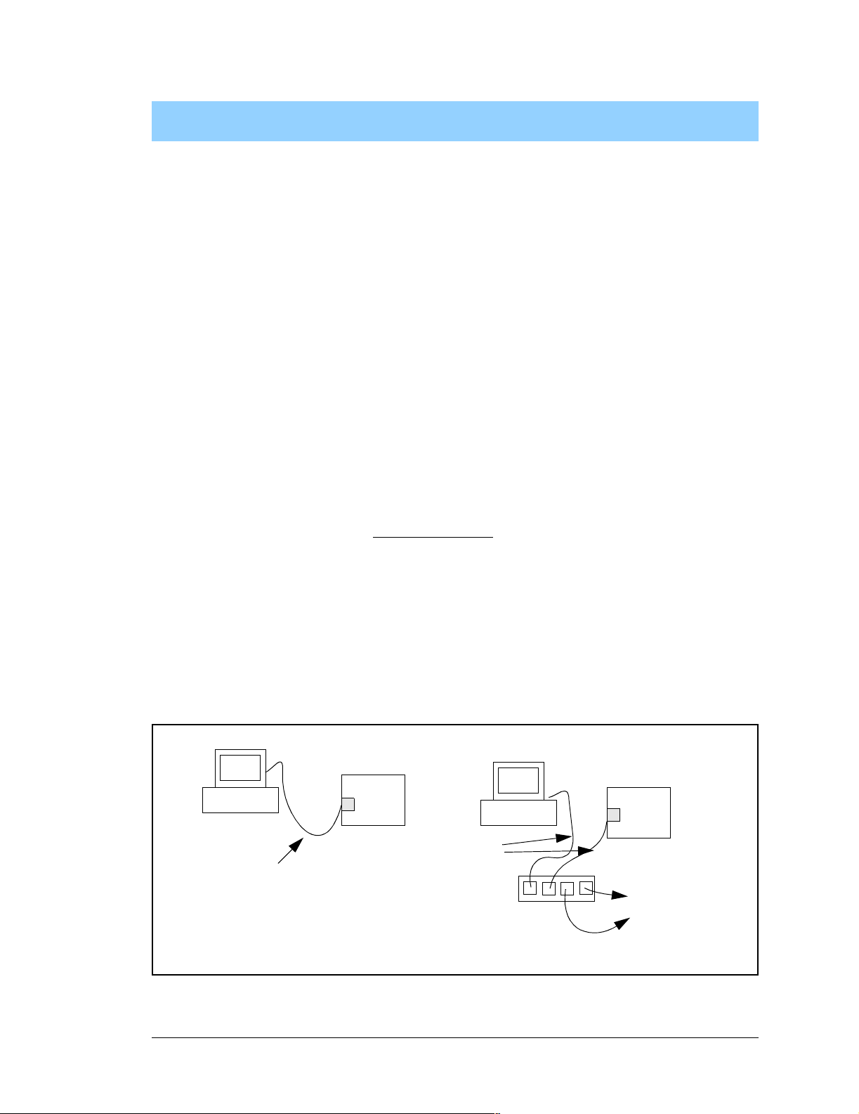
5. USING THE TCP/IP FEATURES
Chapter 5 provides an introduction to using th e TCP/IP features
on your BL2000 board.
5.1 TCP/IP Connections
Before proceeding you will need to have the following items.
• If you don’t have Ethernet access, you will need at least a 10Base-T Ethernet card
(available from your favorite computer supplier) installed in a PC.
• Two RJ-45 straight through Ethernet cables and a hub, or an RJ-45 crossover Ethernet
cable.
The Ethernet cables and Ethernet hub are available from Z-World in a TCP/IP tool kit.
More information is available at www.zworld.com.
1. Connect the AC adapter and the programming cable as shown in Chapter 2, “Getting
Started.”
2. Ethernet Connections
If you do not have access to an Ethernet network, use a crossover Ethernet cable to connect the BL2000 to a PC that at least has a 10Base-T Ethernet card.
If you have Ethernet access, use a straight through Ethernet cable to establish an Ethernet
connection to the BL2000 from an Ethernet hub. These connections are shown in Figure 21.
BL2000
User’s PC
Ethernet
crossover
cable
Direct Connection
(Network of 2 computers)
Figure 21. Ethernet Connections
Board
Ethernet
cables
Hub
Direct Connection Using a Hub
BL2000
Board
To additional
network
elements
User’s Manual 51
Page 56

The PC running Dynamic C through the serial programming port on the BL2000 does not
need to be the PC with the Ethernet card.
3. Apply Power
Plug in the AC adapter. The BL2000 is now ready to be used.
NOTE: A hardware RESET is accomplished by unplugging the AC adapter, then plug-
ging it back in, or by momentarily grounding the boar d re set input at pin 9 on screw terminal header J2.
When working with the BL2000, the green LNK light is on when a program is running and
the board is properly connected either to an Ethernet hub or to an active Ethernet card. The
orange ACT light flashes each time a packet is received.
52 Wildcat (BL2000)
Page 57

5.2 TCP/IP Sample Programs
W e have provided a number of sample programs demonstrating various uses of TCP/IP for
networking embedded systems. These programs require that you connect your PC and the
BL2000 together on the same network. This network can be a local private network (preferred for initial experimentation and debugging), or a connection via the Internet.
5.2.1 How to Set IP Addresses in the Sample Programs
With the introduction of Dynamic C 7.30 we have taken steps to make it easier to run
many of our sample programs. Instead of the MY_IP_ADDRESS and other macros, you will
see a TCPCONFIG macro. This macro tells Dynamic C to select your configuration from a
list of default configurations. You will have three choices when you encounter a sample
program with the TCPCONFIG macro.
1. You can replace the TCPCONFIG macro with individual MY_IP_ADDRESS,
MY_NETMASK, MY_GATEWAY, and MY_NAMESERVER macros in each program.
2. Y ou can leave TCPCONFIG at the usual default of 1, which will set the IP configurations
to 10.10.6.100, the netmask to 255.255.255.0, and the nameserver and gateway
to 10.10.6.1. If you would like to change the default values, for example, to use an IP
address of 10.1.1.2 for the BL2000 board, and 10.1.1.1 for your PC, you can edit
the values in the section that directly follows the “General Configuration” comment in
the TCP_CONFIG.LIB library. You will find this library in the LIB\TCPIP directory.
3. You can create a CUSTOM_CONFIG.LIB library and use a TCPCONFIG value greater
than 100. Instructions for doing this are at the beginning of the TCP_CONFIG.LIB file.
There are some other “standard” configurations for TCPCONFIG that let you select different features such as DHCP. Their values are documented at the top of the
TCP_CONFIG.LIB library. More information is available in the Dynamic C TCP/IP
User’s Manual.
IP Addresses Before Dynamic C 7.30
Most of the sample programs such as shown in the example below use macros to define the
IP address assigned to the board and the IP address of the gateway, if the re is a ga te way.
#define MY_IP_ADDRESS "10.10.6.170"
#define MY_NETMASK "255.255.255.0"
#define MY_GATEWAY "10.10.6.1"
#define MY_NAMESERVER "10.10.6.1"
In order to do a direct connection, the following IP addresses can be used for the BL2000:
#define MY_IP_ADDRESS "10.1.1.2"
#define MY_NETMASK "255.255.255.0"
// #define MY_GATEWAY "10.10.6.1"
// #define MY_NAMESERVER "10.10.6.1"
In this case, the gateway and nameserver are not used, and are commented out. The IP
address of the board is defined to be 10.1.1.2. The IP address of you PC can be defined
as 10.1.1.1.
User’s Manual 53
Page 58
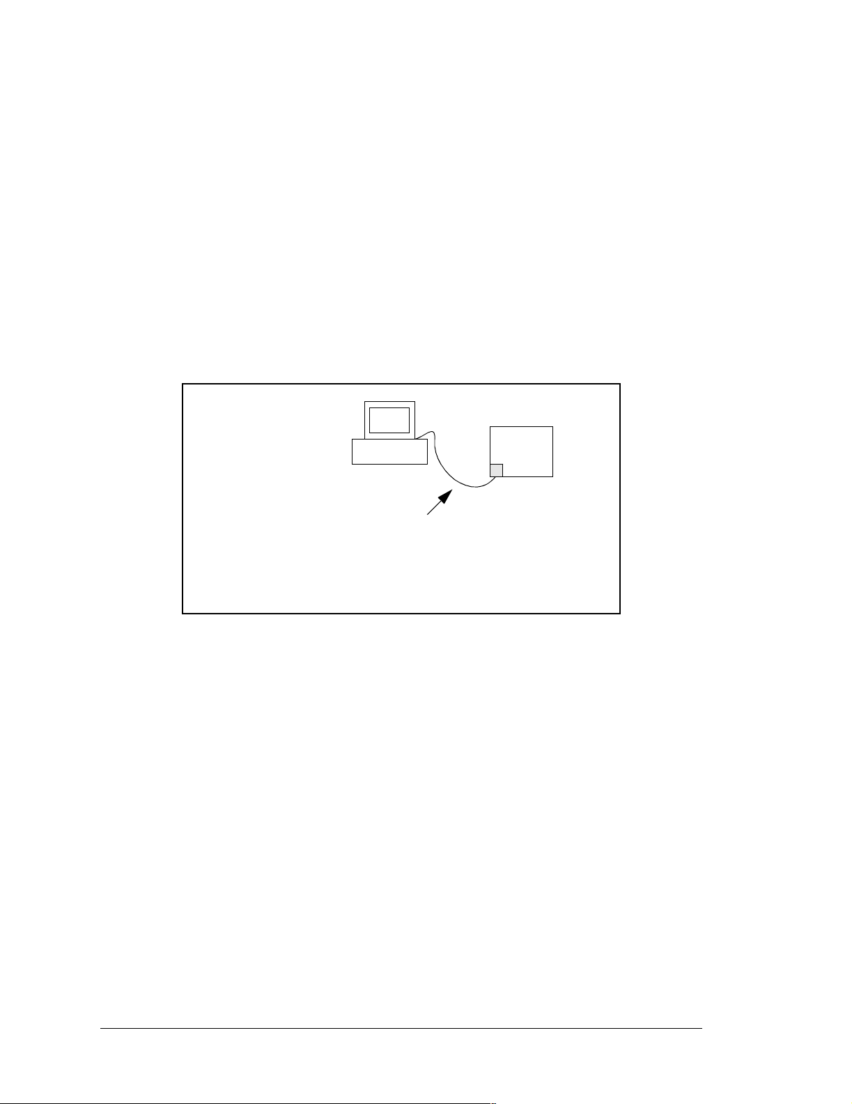
5.2.2 How to Set Up your Computer’s IP Address for a Direct Connection
When your computer is connected directly to the BL2000 via an Ethernet connection, you
need to assign an IP address to your computer. To assign the PC the address
10.10.6.101 with the netmask 255.255.255.0, do the following.
Click on
Start > Settings > Control Panel to bring up the Control Panel, and then dou-
ble-click the Network icon. Depending on which version of Windows you are using, look
for the TCP/IP Protocol/Network > Dial -Up Connections/Network line or tab. Double-
click on this line or select Properties or Local Area Connection > Properties to bring
up the TCP/IP properties dialog box. You can edit the IP address and the subnet mask
directly. (Disable “obtain an IP address automatically.”) You may want to write down the
existing values in case you have to restore them later. It is not necessary to edit the gateway address since the gateway is not used with direct connect.
BL2000
IP 10.10.6.101
Board
Netmask
255.255.255.0
User’s PC
Ethernet
crossover
cable
Direct Connection PC to BL2000 Board
54 Wildcat (BL2000)
Page 59

5.3 Run the PINGME.C Sample Program
Connect the crossover cable from your computer’s Ethernet port to the BL2000’s RJ-45
Ethernet connector. Open this sample program from the SAMPLES\TCPIP\ICMP folder,
compile the program, and start it running under Dynamic C. When the program starts running, the green LNK light on the BL2000 should be on to indicate an Ethernet connection
is made. (Note: If the LNK light does not light, you may not have a crossover cable, or if
you are using a hub perhaps the power is off on the hub.)
The next step is to ping the board from your PC. This can be done by bringing up the MSDOS window and running the pingme program:
ping 10.10.6.100
or by Start > Run
and typing the entry
ping 10.10.6.100
Notice that the orange ACT light flashes on the BL2000 while the ping is taking place, and
indicates the transfer of data. The ping routine will ping the board four times and write a
summary message on the screen describing the operation.
User’s Manual 55
Page 60

5.4 Running More Sample Programs With a Direct Connection
The program SSI.C (SAMPLES\BL2000\TCPIP\) demonstrates how to make the
BL2000 a Web server. This program allows you to turn the LEDs on an attached Demonstration Board from the Tool Kit on and off from a remote Web browser. LEDs DS4–DS8
on the BL2000 will match those on the Web page. As long as you have not modified the
TCPCONFIG 1 macro in the sample program, enter the following server address in your
Web browser to bring up the Web page served by the sample program.
http://10.10.6.100
Otherwise use the TCP/IP settings you entered in the TCP_CONFIG.LIB library.
The sample program
SMTP.C (SAMPLES\BL2000\TCPIP\) allows you to send an E-mail
when a switch on the Demonstration Board is pressed. Follow the instructions included
with the sample program.
The sample program TELNET.C (SAMPLES\BL2000\TCPIP\) allows you to communicate with the BL2000 using the Telnet protocol. This program takes anything that comes
in on a port and sends it out Serial Port B. It uses digital input IN0 to indicate that the
TCP/IP connection should be closed, and it uses high-current output OUT0 to indicate that
there is an open connection. You may change the digital input and output to suit your
application needs.
Run the Telnet program on your PC (Start > Run telnet 10.10.6.100). As long as
you have not modified the TCPCONFIG 1 macro in the sample program, the IP address is
10.10.6.100 as shown; otherwise use the TCP/IP settings you entered in the
TCP_CONFIG.LIB library . Each character you type will be printed in Dynamic C's STDIO
window, indicating that the board is receiving the characters typed via TCP/IP.
5.5 Where Do I Go From Here?
NOTE: If you purchased your BL2000 through a distributor or Z-World partner, contact
the distributor or Z-World partner first for technical support.
If there are any problems at this point:
• Check the Z-W orld Technical Bulletin Board at www.zworld.com/support/bb/.
• Use the T echn ical Support e-mail form at www.zworld.com/support/support_submit.htm l.
If the sample programs ran fine, you are now ready to go on.
Additional sample programs are described in the Dynamic C TCP/IP User’s Manual.
Refer to the Dynamic C TCP/IP User’s Manual to develop your own applications. An
Introduction to TCP/IP provides background information on TCP/IP, and is available on
Z-World’s Web site.
56 Wildcat (BL2000)
Page 61

APPENDIX A. SPECIFICATIONS
Appendix A provides the specifications for the BL2000 and
describes the conformal coating.
User’s Manual 57
Page 62
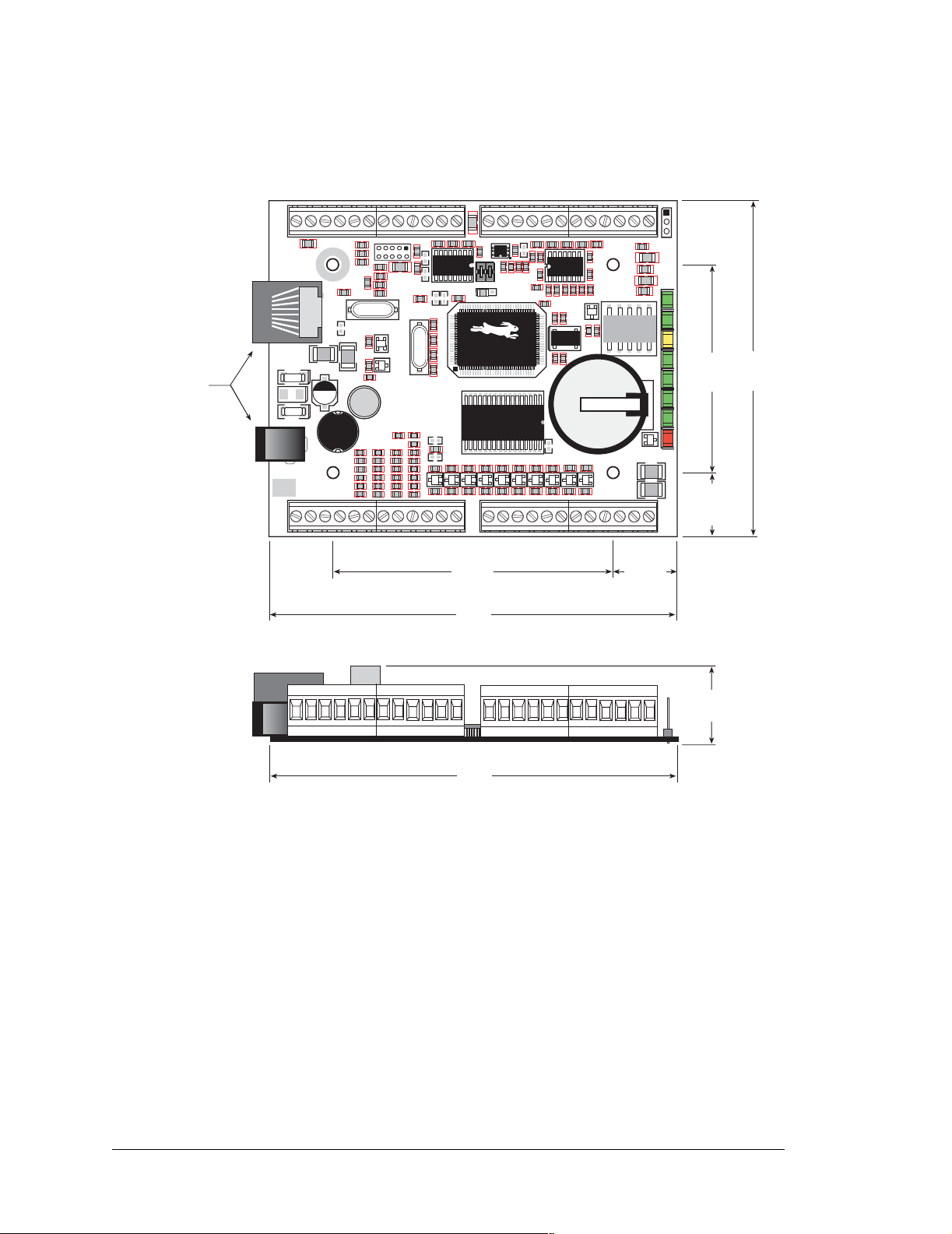
A.1 Electrical and Mechanical Specifications
Figure A-1 shows the mechanical dimensions for the BL2000.
Jacks extend
0.16" (4.0 mm)
past edge of
board
GND RST- IN1 IN0 485- 485+ RXD2 TXD2 RXD1 TXD1 AGND DAC1 DAC0 ADC8 ADC7 ADC6 ADC5 ADC4 ADC3 ADC2 ADC1 ADC0+RAW +K
J1
TVS1
J2
J6
C23
D1
GND GND
R1
GND
C20
C25
C28
R4
R6
C17
R20
C24
C10
R151
GN D
GND GND
J5
R13
R12
C80
R130
R16
R15
R19
C16
C19
Y3
Y2
U4
Q2
R30
C29
+
D2
14
23
J7
POWER IN
GND
J8
J10
IN3IN2 IN4 IN5 IN6 IN7 IN8 IN9 IN10 OUT8 OUT9 GND GNDOUT0 OUT1 OUT2 OUT3 OUT4 OUT5 OUT6 OUT7 NC
+
C31
L1
R31
R33
C34
C33
C35
R36
R37
R38
R51
R52
C38R50
C39
C40
R55
R54
R56
R60
R59
R58
GN D
C85
J4
J3
AGND
AGND
C2
R154
C3
C8
U1
C18
C1
R9
R153
U5
R27C22
90
R28
C27
AGND
C75
R5
R2
C79
U2
R7
C4
R157
R10
R11
C11
JP1
R17
C13
JP2
C76
R152
R22
65
15
C21
40
C26
U6
R32
R34
R35
R40
D3
C36
R39
R41
R43 R44
R42
D4
C41R53
R57
R61
C44
C43
GNDGNDGNDGND
GND
2.85
(105)
D5
C45
(72)
4.15
D6
C46
D7 D8 D9
C47
GND
C32
R47
R45
R46
D10
C50
C49C48
GND
AG ND
C78
R23
C14
R24
Y1
1432
R29
Q3
Battery
Q5
R48
D11 D12
C51
GN D
AGND
AGND
R3
C5
R8
U3
R18
C15
C77
Q1
56
R25
R26
Q4
S
D
G
R49
J12
C7
+
C9
R14
C12
DS1
R21
K1
BT1
Q6
PWRLNKACTOUT 0OUT 1OUT 2OUT 3BAD
1
DS3DS2
10
DS4
DS5
DS6
+
DS7
+
DS8
2.13
C37
(54)
(87)
3.43
C42
C52
GND
GND
GND
J11
COM
0.65
(16.5)
J9
NO
0.65
(16.5)
0.82
(21)
4.15
(105)
Figure A-1. BL2000 Dimensions
NOTE: All measurements are in inches followed by millimeters enclosed in parentheses.
58 Wildcat (BL2000)
Page 63

Table A-1 lists the electrical, mechanical, and environmental specifications for the BL2000.
Table A-1. BL2000 Specificat ions
Feature BL2000 BL2010 BL2020 BL2030
Microprocessor
Rabbit 2000
®
at 22.1 MHz
Ethernet Port 10Base-T, LNK and ACT LEDs None
Flash Memory 256K (standard)
SRAM 128K (standard)
Panasonic CR2330 or equivalent 3 V lithium coin type, 265 mA·h
Backup Battery
standard using onboard battery holder; optional 3 V, 950 mA·h
solder-in battery available; external battery connector
Digital Inputs
Digital Outputs
Analog Inputs
Analog Outputs
Dual-Purpose Analog or Digital
Inputs
200 mA maximum per channel (2 channels can sink up to 750 mA each)
Four 12-bit res.,
± 10 V DC, 1 MΩ,
up to 4,000
samples/s
Two 12-bit res.,
0–4 V DC,
update rate 12 kHz
Five at 12
12-bit res.,
0–48 V DC
11 inputs hardware-configurable pull-up or pull-down,
± 36 V DC, switchin g threshold 2.4 V typical
10 outputs sinking or sourcing, +40 V DC,
Four 10-bit res.,
± 10 V DC, 1 MΩ,
kΩ,
Seven at 12 kΩ,
up to 4,000
samples/s
None
10-bit res.,
0–48 V DC
Four 12-bit res.,
± 10 V DC, 1 MΩ,
up to 4,000
samples/s
Two 12-bit res.,
0–4 V DC,
update rate 12 kHz
Five at 12 kΩ,
12-bit res.,
0–48 V DC
Four 10-bit res. ,
± 10 V DC, 1 MΩ,
up to 4,000
samples/s
None
Seven at 12 kΩ,
10-bit res.,
0–48 V DC
SPDT with snubbers
Relay Output
*
: 1 A @ 30 V DC, 300 mA @ 120 V AC
(uses one digital output)
max. contact settling time 4 ms
4 serial ports:
• two RS-232 or one RS-232 (with CTS/RTS)
Serial P orts
• one RS-485, onboard network termination and bias resistors
• one 5 V CMOS-compatible programming port
Serial Rate
one RJ-45 (Ethernet)
one 2 × 5, 2 mm pitch (serial programming port)
Connectors
one power jack for AC adapter
four 12-terminal s crew connector s (14 AWG/1.5 mm
and digital I/O, relay
Real-Time Clock Yes
User’s Manual 59
Max. burst rate = CLK/32
Max. sustained rate = CLK/64
2
wire) for analog
Page 64
Table A-1. BL2000 Specifications (continued)
Feature BL2000 BL2010 BL2020 BL2030
Timers
Five 8-bit timers (four are cascadable from the first) and
one 10-bit timer with two match registers
W atchdog/Supervisor Yes
Power 9–40 V DC or 24 V AC (±10%), 1.5 W max.
Operating Temperature –40°C to +70°C
Humidity 5–95%, noncondensing
Board Size
3.43" × 4.15" × 0.82"
(87 mm × 105 mm × 21 mm)
* When using the BL2000 in a CE-certified application, th e voltages handled by the relay must
not exceed SELV levels (42.4 V AC peak, or 60 V DC).
60 Wildcat (BL2000)
Page 65
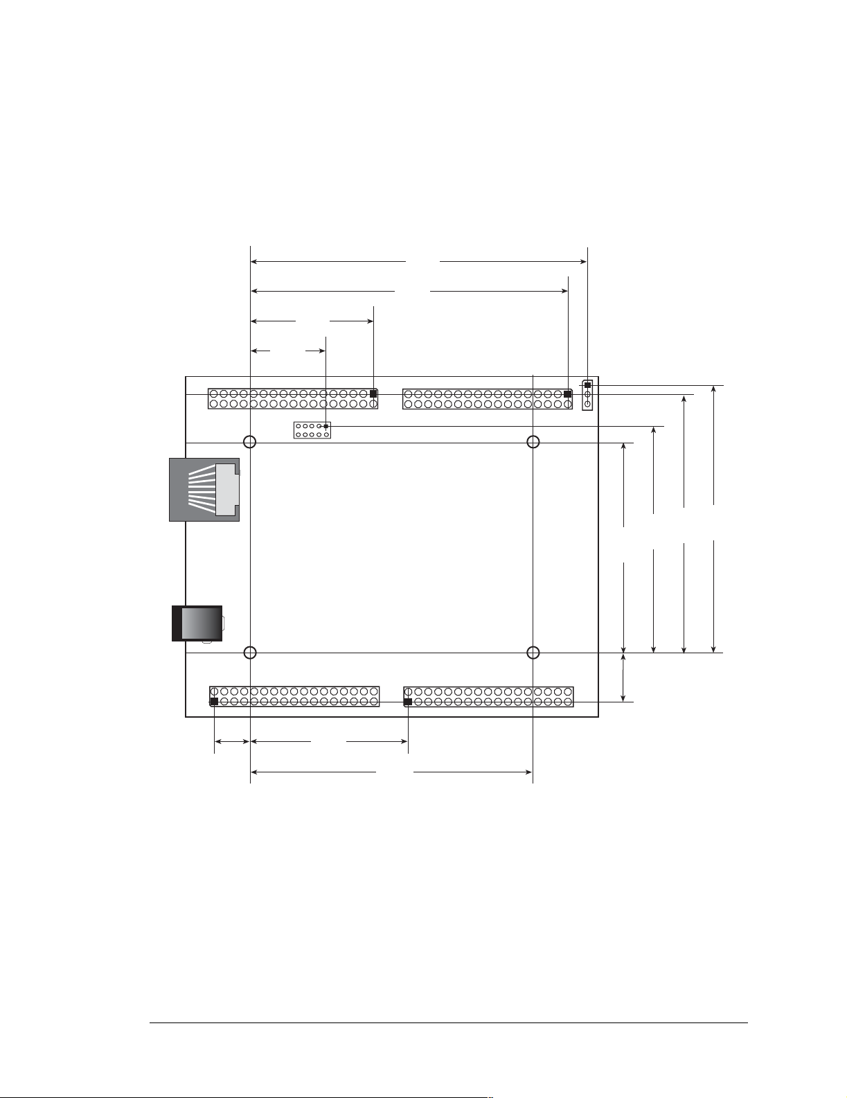
A.1.1 Headers
The BL2000 has an option for 0.1" IDC headers or friction-lock connectors at J1, J3, J10,
and J11 for physical connection to other boards or ribbon cables.
Figure A-2 shows the BL2000 footprint. These values are relative to one of the mounting
holes.
3.380
(85.9)
3.189
(81.0)
1.239
(31.5)
0.760
(19.3)
0.361
(9.2)
J1
J6
J7
J10
J5
J3
J11
1.589
(40.4)
2.839
(72.1)
Figure A-2. User Board Footprint for BL2000
J12
(53.7)
2.113
(12.4)
0.487
(57.9)
2.280
(66.0)
2.598
(67.1)
2.641
User’s Manual 61
Page 66
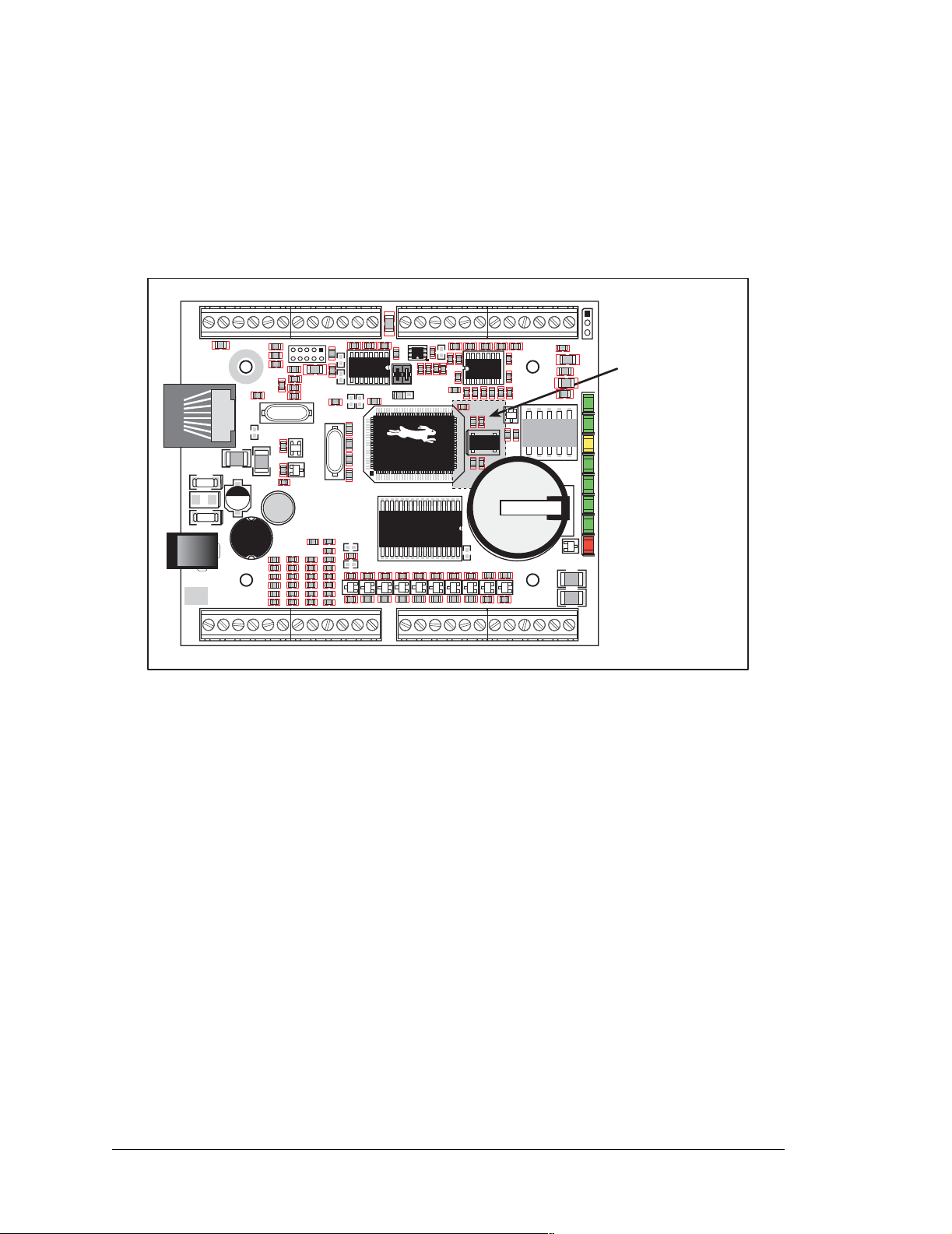
A.2 Conformal Coating
The areas around the crystal oscillator and the battery backup circuit on the BL2000 have
had the Dow Corning silicone-based 1-2620 conformal coating applied. The conformally
coated areas are shown in Figure A-3. The conformal coating protects these high-impedance circuits from the effects of moisture and contaminants over time.
GND RST- IN1 IN0 485- 485+ RXD2 TXD2 RXD1 TXD1 AGND DAC1 DAC0 ADC8 ADC7 ADC6 ADC5 ADC4 ADC3 ADC2 ADC1 ADC0+RAW +K
J1
TVS1
J2
J6
C23
D1
GND GND
R1
GND
C20
C25
C28
R4
R6
C17
C10
R20
C24
R12
C16
R151
GN D
GND GND
J5
R13
C80
R130
R16
R15
R19
C19
Y3
Y2
U4
Q2
R30
C29
+
D2
14
23
J7
POWER IN
GND
J8
J10
IN3IN2 IN4 IN5 IN6 IN7 IN8 IN9 IN10 OUT8 OUT9 GND GNDOUT0 OUT1 OUT2 OUT3 OUT4 OUT5 OUT6 OUT7 NC
+
C31
L1
R31
R33
C34
C33
C35
R36
R37
R38
R51
R52
C38R50
C39
C40
R55
R54
R56
R60
R59
R58
GN D
C85
J4
J3
AGND
AGND
C2
C3
C75
C18
U2
C8
R157
R10
R11
JP1
U1
90
C13
JP2
65
15
C1
R9
R153
R154
U5
R27C22
R28
C27
U6
R32
R34
R35
R40
D3
C36
R39
R41
R42
D4
D5
C41R53
R57
R61
C44
C43
C45
GNDGNDGNDGND
GND
R43 R44
D6
C46
R45
D7 D8 D9
C47
GND
AG ND
AGND
R5
C79
R2
C78
R7
C4
C11
R17
C76
R23
C14
R152
R22
C21
R24
Y1
40
1432
R29
C26
Q3
Battery
Q5
C32
R48
R47
R46
D11 D12
D10
C51
C50
C49C48
GN D
GND
AGND
AGND
R3
C5
R8
U3
R18
C15
C77
Q1
56
R25
R26
Q4
S
D
G
R49
R21
J12
C7
+
C9
C12
PWRLNKACTOUT 0OUT 1OUT 2OUT 3BAD
DS4DS3DS2
DS8
C37
Conformally
coated area
K1
BT1
Q6
R14
DS1
1
10
DS5
DS6
+
DS7
+
C42
C52
GND
GND
GND
J11
NO
J9
COM
Figure A-3. BL2000 Areas Receiving Conformal Coating
Any components in the conformally coated area may be replaced using standard soldering
procedures for surface-mounted components. A new conformal coating should then be
applied to offer continuing protection against the effects of moisture and contaminants.
NOTE: For more information on conformal coatings, refer to Rabbit Semiconductor
Technical Note 303, Conformal Coatin gs.
62 Wildcat (BL2000)
Page 67
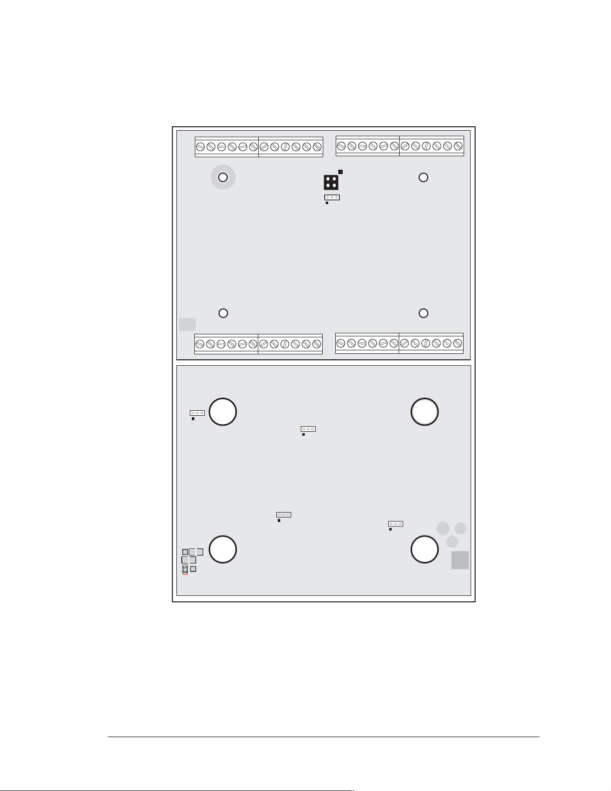
A.3 Jumper Configurations
Figure A-4 shows the header locations used to configure the various BL2000 options via jumpers.
JP1
JP2
Top Side
GND
JP3
JP4
JP5
JP6
TP15
R160
R161
TP17
R118
Bottom Side
Figure A-4. Location of BL2000 Configurable Positions
GND
User’s Manual 63
Page 68

Table A-2 lists the configuration options.
Table A-2. BL2000 Jumper Configurations
Header Description Pins Connected
Pin 12 is Vcc R160 installed
J9
Pin 12 is GND R161 installed
1–2
Bias and termination resistors
3–4
JP1
JP2 Flash Memory Bank Select
JP3 D/A Converter Power Supply
JP4 Flash Memory Size
RS-485 Bias and Termination
Resistors
connected
Bias and termination resistors not
None
connected
1–2 Normal Mode
2–3 Bank Mode
1–2 +V
2–3 +REF
1–2 128K/256K
2–3 512K
Factory
Default
×
×
×
×
×
1–2 128K
JP5 SRAM Size
2–3 512K
JP6
Digital Input Pull-Up/Pull-Down
Resistors
NOTE: Only header JP1 uses actual jumpers. The other connections are made using 0 Ω
surface-mounted resistors.
1–2 Pulled up
2–3 Pulled down
×
×
64 Wildcat (BL2000)
Page 69
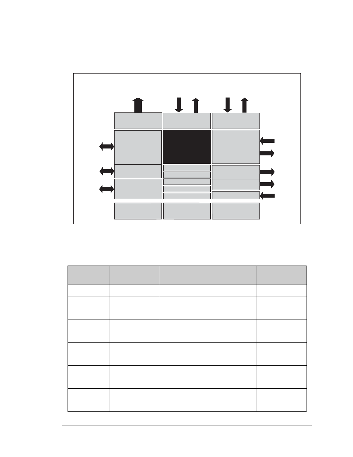
A.4 Use of Rabbit 2000 Parallel Ports
Figure A-5 shows the Rabbit-based subsystems designed into the BL2000.
PD0
PD1
PA0PA7
PB0
PB5
PB6
PB7
PD2
PD3
PD4
PB7
Port B
(IN6IN10, CTRL)
R
ABBIT
2000
Real-Time Clock
Watchdog
7 Timers
Slave Port
Clock Doubler
Backup Battery
Support
Port D
(ADC, DAC, Eth)
Port E
(IN0IN5
OUT8OUT9)
Address Lines
I/O Control
Misc. Input
Flash
PC0PC5
PC6PC7
DA0DA7
Port A
(OUT0OUT7)
Serial Ports
(Port C)
Programming
Port
Data Lines
RAM
Figure A-5. BL2000 Rabbit-Based Subsystems
Table A-3 lists the Rabbit 2000 parallel ports and their use in the BL2000.
Table A-3. Use of Rabbit 2000 Parallel Port s
Port I/O Signal
Output Function
PE2PE7
PE0, PE1
A0A18
IORD
IOWR
RESET
State
PA0 Output OUT0/RELAY/LED_DS4 Off
PA1 Output OUT1/LED_DS5 Off
PA2 Output OUT2/LED_DS6 Off
PA3 Output OUT3/LED_DS7 Off
PA4 Output OUT4 Off
PA5 Output OUT5 Off
PA6 Output OUT6 Off
PA7 Output OUT7 Off
PB0 Input IN6 N/A
PB1 Input CLKA N/A
PB2 Input IN7 N/A
User’s Manual 65
Page 70

Table A-3. Use of Rabbit 2000 Parallel Ports (continued)
Port I/O Signal
Output Function
State
PB3 Input IN8 N/A
PB4 Input IN9 N/A
PB5 Input IN10 N/A
PB6 Output RS485_EN Off
PB7 Output UPGOOD Off
PC0 Output TXD RS-485
Inactive high
Serial Port D
PC1 Input RXD RS-485 N/A
PC2 Output RTS/TXC RS-232
Inactive high
Serial Port C
PC3 Input CTS/RXC RS-232 N/A
PC4 Output TXB RS-232
Inactive high
Serial Port B
PC5 Input RXB RS-232 N/A
PC6 Output TXA Programmi ng Po rt
Inactive high
Serial Port A
PC7 Input RXA Programming Port N/A
PD0 Output DAC-ADC_SK On
PD1 Output DAC-ADC_SDI On
PD2 Input RTL-ADC_SDO N/A
PD3 Input RTL_SK
N/A
*
PD4 Output RTL_SDI On
PD5 Output /DAC0_CS Inactive high
PD6 Output /DAC1_CS Inactive high
PD7 Output /ADC_CS Inactive high
PE0 Output OUT8 Off
PE1 Output OUT9 Off
PE2 Input IN0 N/A
PE3 Input IN1 N/A
PE4 Input IN2 N/A
PE5 Input IN3 N/A
PE6 Input IN4 N/A
PE7 Input IN5 N/A
* PD3 is an output (and is on) for the BL2020 and the BL2030.
66 Wildcat (BL2000)
Page 71

APPENDIX B. PLASTIC ENCLOSURE
The plastic enclosure provides a secure way to protect your
BL2000. The enclosure itself ma y be mounted on any flat surface.
Appendix B d esc ribe s how t o mo unt t he BL200 0 i nsi de th e pl astic enclosure, how to install the optional light pipes, and provides details on mounting the assembly.
User’s Manual 67
Page 72
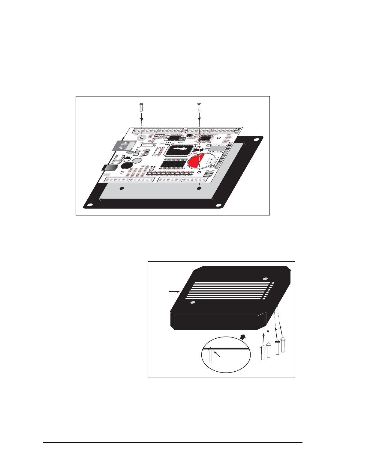
B.1 Assembly
1. Attach the BL2000 to the plastic enclosure base.
Positi o n the
BL2000
over the plastic enclosure base as shown below in Figure B-1.
the BL2000 to the base using the two 4-40 × ¼ screws supplied.
C1
R9
R154
D7 D8 D9
GND
C85
J4
J3
AGND
C75
R5
C79
R7
C4
R
C
1
1
1
1
R17
C76
R152
R22
C21
1432
R29
C26
D
Q3
Q5
CAUTION
R49
GND
GND
NO
COM
AGND
R2
R23
C
14
R
2
4
Y1
R
2
5
G
Battery
GND
AG ND
AGND
R3
C78
C5
C7
R8
U3
R18
C
1
5
R21
C77
Q1
1
56
1
0
R
2
6
DS4
K1
DS5
Q4
S
BT1
DS6
+
DS7
+
DS8
Q6
C
37
C
42
J11
J9
AGND
C2
C3
U2
C8
R
R
JP
1
10
5
1
7
U1
C18
90
C13
JP2
6
5
4
0
1
5
U6
C32
R48
R47
R45
R46
D11 D12
D10
C51
C50
C49C48
C52
GN D
GND
GND RST- IN1 IN0 485- 485+ RXD2 TXD2RXD1 TXD1 AGND DAC1 DAC0ADC8 ADC7 ADC6ADC5 ADC4 ADC3ADC2 ADC1 ADC0+RAW +K
J1
J2
J6
C23
D1
TVS1
+
D2
14
23
J7
POWER IN
GND
J8
J10
IN3IN2 IN4 IN5 IN6 IN7 IN8 IN9 IN10 OUT8 OUT9 GND GNDOUT0 OUT1OUT2 OUT3 OUT4OUT5 OUT6 OUT7 NC
8
GN D
GND
GND GND
R1
C25
C28
+
L1
C
3
3
R
3
6
R
5
0
1
C
C
3
3
8
9
R
R
5
5
5
4
R
R
5
5
9
GN D
GND GND
J5
R13
R4
R6
R12
C10
C80
R20
R130
R16
C20
C17
C24
R
151
R30
C29
C31
R33
C
3
3
4
5
R
R
3
3
7
8
R
R
5
5
2
C
4
0
R
5
6
R
6
0
R15
R19
C16
C
C
4
1
R
5
7
R
6
1
C43
GNDGNDGNDGND
R153
C19
Y3
U5
Y2
C
2
2
R
27
U4
R
2
8
C
2
Q2
7
R32
R34
R35
R40
R31
D3
C
3
6
R
R41
R43 R44
R42
3
9
D4
D5
D6
R
5
3
C47
C46
C44
C45
GND
Figure B-1. Attach BL2000 to Plastic Enclosure Base
2. Install light pipes (optional).
Attach
AGND
J12
+
C9
R14
C12
DS1
PWRLNKACTOUT 0OUT 1OUT 2OUT 3BAD
DS2
DS3
Light pipes are included in the
Tool Kit to facilitate seeing the
LEDs on the BL2000 board
once the enclosure is assembled.
Notched
With the enclosure top posi-
side
tioned as shown in Figure B-2,
insert the eight light pipes into
the slots identified in Figure B-
2. Position the light pipes snugly
against the enclosure top since
there is little clearance between
the light pipes and the LEDs on
the BL2000. The light pipes
Light pipe
flange is firmly
against
enclosure
“snap” in place. Verify that the
light pipes are aligned over the
LEDs, then apply a drop of
Figure B-2. Install Light Pipes in Enclosure Top
cyanoacrylate or contact cement
to the inside of the enclosure around each light pipe to hold it in place.
NOTE: Once the glue is applied, it wi ll not be possible to change the alignment of the
light pipes without damaging the plastic enclosure.
...
68 Wildcat (BL2000)
Page 73
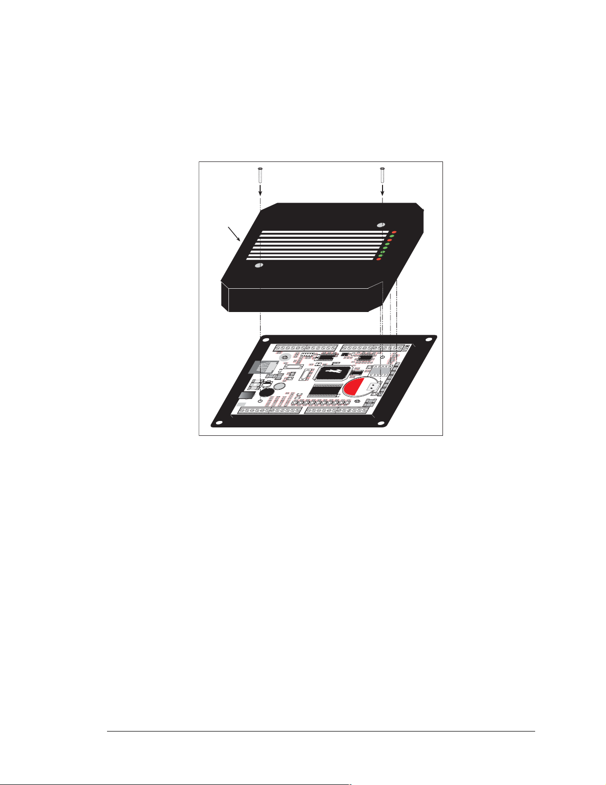
3. Attach the enclosure top to the base.
Position the enclosure top over the plastic enclosure base as shown below in Figure B-3.
Attach the enclosure top to the base using the two 4-40 × ½ screws supplied. If you
installed the light pipes, be sure they are aligned over the LEDs as shown.
Notched
side
GND RST- IN1 IN0 485- 485+ RXD2 TXD2 RXD1TXD1 AGND DAC1DAC0 ADC8 ADC7ADC6 ADC5 ADC4ADC3 ADC2 ADC1ADC0+RAW +K
J1
J2
GND
GN D
GND GND
R1
J6
C23
D1
C25
T
C28
V
S
1
+
D2
14
+
L1
23
C
3
3
R
3
6
R
J7
POWER IN
J8
J10
5
0
C
C
3
3
8
9
R
R
5
5
5
4
R
R
5
5
GND
IN3IN2 IN4 IN5 IN6 IN7 IN8 IN9 IN10 OUT8 OUT9 GND GNDOUT0 OUT1OUT2 OUT3 OUT4OUT5 OUT6 OUT7 NC
9
8
GN D
J5
R4
R6
R12
C10
C80
R20
R130
R16
C20
R19
C16
C19
Y3
Y2
C17
C24
U4
R
151
2
Q2
7
R30
C29
R32
R34
R35
R40
C31
R31
D3
R33
C
C
C
3
3
3
4
6
5
R
R
R
R41
R42
3
3
3
7
9
8
D4
D5
R
R
R
5
5
5
1
3
2
C
C
4
4
0
1
R
R
5
5
7
6
R
R
6
6
0
1
C46
C44
C43
C45
GNDGNDGNDGND
GND
R15
R153
R
2
8
C
GND GND
R13
U5
C
2
2
R
2
7
R43 R44
D6
C47
GND
C1
R9
D7 D8 D9
J4
J3
C
C
3
2
AGND
AGND
AGND
C75
R5
C79
U2
R7
C4
C8
R
R
C
1
1
1
R17
1
1
0
U1
JP2
R154
C13
C76
R152
C18
R22
C21
6
4
5
9
4
0
0
1432
1
5
R29
C26
D
U6
Q3
G
Q5
CAUTION
C32
R48
R47
R49
R45
R46
D11 D12
D10
C51
C50
C52
C49C48
GND
GND
GND
GN D
NO
COM
C
1
4
R
2
Y1
B
R2
R
2
3
R
2
5
Q4
attery
GND
AGND
AG ND
AGND
C78
R3
J12
C5
C7
+
R8
C9
U3
R14
R18
C12
C
1
5
D
R21
S1
R
Q1
56
K1
BT1
+
S
7
+
DS8
C
37
C
42
W
P
DS
1
K
2
LN
D
1
S
0
3
CT
A
D
T 0
S4
U
O
DS5
UT 1
O
DS
T 2
6
U
O
D
T 3
U
O
AD
B
C77
R
2
6
S
Q6
J11
J9
Figure B-3. Attach Enclosure Top
4. Mount plastic enclosure (optional).
Use four #10 screws to attach the assembled plastic enclosure to the surface on which it
will be mounted. This step applies to production versions of BL2000 boards once development has been completed.
User’s Manual 69
Page 74
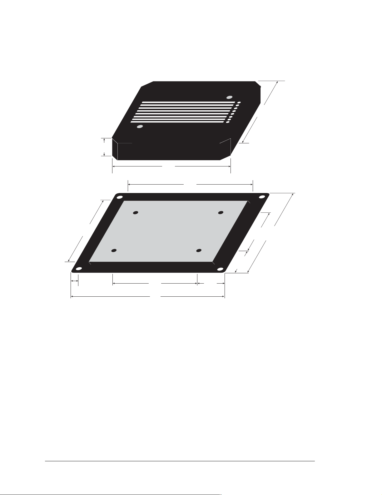
B.2 Dimensions
Figure B-4 shows the dimensions for the plastic enclosure.
0.70
(18)
5.00
(127)
4.35
(110)
4.25
(108)
0.375" (9.5 mm)
is cut off each corner
(92)
0.25
(6.4)
3.62
2.85
(72)
5.60
(142)
1.375
(35)
1.375
(35)
2.13
(54)
(124)
4.875
Figure B-4. Plastic Enclosure Dimensions
When fully assembled with the BL2000 installed, the total height of the plastic enclosure
will be 1.1" (28 mm).
70 Wildcat (BL2000)
Page 75
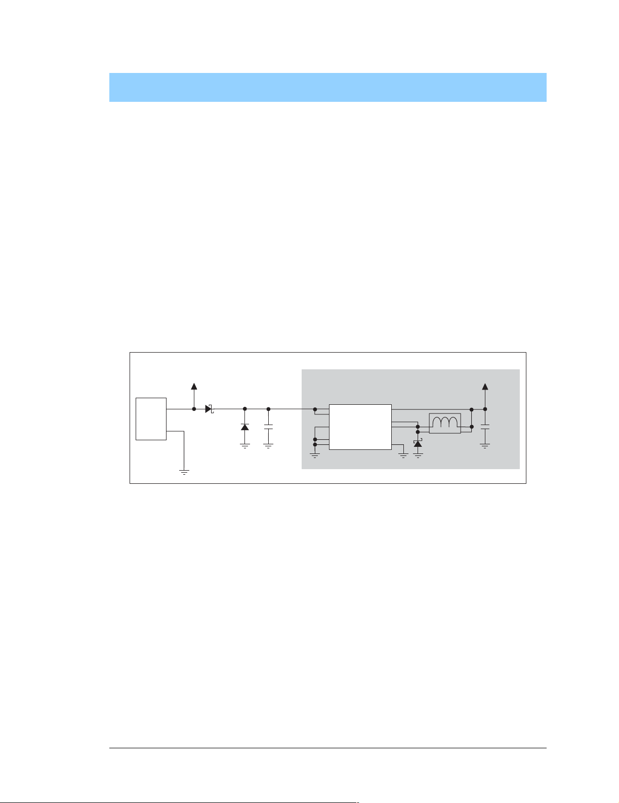
APPENDIX C. POWER SUPPLY
Appendix C describes the power circuitry distributed on the
BL2000.
C.1 Power Supplies
Power is supplied to the BL2000 via a mini phone jack located at J7 or through the screw
terminal strip, header J2. The BL2000 itself is protected against reverse polarity by a
diode at D1 as shown in Figure C-1.
J2 orJ7
POWER
IN
+RAW
D1
TVS1
SWITCHING POWER REGULATOR
DCIN
C28
47 µF
14
15
12
8
1
U12
LM2575
7
17
18
10
2
330 µH
1
L1
D2
1N5819
Vcc
C29
4
330 µF
3
Figure C-1. BL2000 Power Supply
Capacitor C28 provides surge current protection for the voltage regulator, and allows the
external power supply to be located some distance away from the BL2000. A switching
power regulator is used. The input voltage range is from 9 V to 40 V.
The BL2000 can alternatively be powered by 24 V AC. In this case D1 and C28 act as a
half-wave rectifier to produce approximately 40 V DC at the input of the switching regulator, U12. Although a significant drop will be measured at DCIN, the voltage will never
drop below +9 V DC. As long as the minimum input level is maintained at the input to the
regulator, Vcc will be held at +5 V DC.
Pin 12 on header J9 can be configured to either supply Vcc (0 Ω surface-mounted resistor
installed at R160) or GND (0 Ω surface-mounted resistor installed at R161). When using
pin 12 on header J9 to supply Vcc, take care not to draw more than 25 mA current from
this pin, especially if you are using 24 V AC as your +RAW input power supply. The R160
and R161 locations are shown in Figure A-4.
User’s Manual 71
Page 76

C.1.1 Power for Analog Circuits
Power to the analog circuits is provided by way of a two-stage low-pass filter, which isolates the analog section from digital noise generated by the other components. The analog
power voltage +V powers the op-amp for the buffered A/D converter inputs, the A/D converter, and the 4.096 V reference circuit. The two D/A converters can be powered either
from the reference, which is t he st andar d, or from + V when r atiome tr ic me asure men ts are
desired. The maximum current draw on +V is less than 10 mA.
There are three digital grounds, one on each of the screw-terminal headers associated with
the digital functions (J2, J8, and J9). The digital ground and the analog ground share a single split ground plane on the board, with the analog ground connected at a single point to
the digital ground by a 0 Ω resistor (R87). This is done to minimize digital noise in the
analog circuits and to eliminate the possibility of ground loops. External connections to
analog ground are made on screw-terminal header J4.
C.2 Batteries and External Battery Connections
The SRAM and the real-time clock have battery backup. Power to the SRAM and the realtime clock (VRAM) is provided by two different sources, depending on whether the main
part of the BL2000 is powered or not. When the BL2000 is powered normally, and Vcc is
within operating limits, the SRAM and the rea l-time cl ock ar e power ed fr om Vcc. If power
to the board is lost or falls below 4.63 V, the VRAM power will come from the battery. The
reset generator circuit controls the source of power by way of its /RESET output signal.
A replaceable 265 mA·h lithium battery provides power to the real-time clock and SRAM
when external power is removed from the circuit board. The drain on the battery is typically
less than 10 µA when there is no external power applied, and so the expected in-service life
of the battery is
265 mA·h
------------------------ 3.0 years.=
10 µA
The drain on the battery is typically less tha n 4 µA when external power is applied, and so
the expected BL2000 shelf life is
265 mA·h
------------------------ 7.5 yea rs.=
4 µA
A long-life 950 mA·h solder-in battery is also provided for in the board layout. Alternatively, an external battery may be connected to the BL2000 via header J12. The existing
battery does not have to be removed when an external battery is used.
72 Wildcat (BL2000)
Page 77
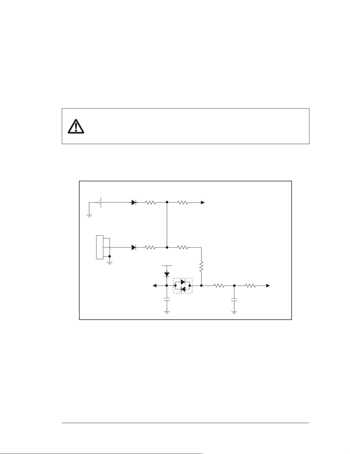
C.2.1 Replacing the Backup Battery
The battery is user-replaceable, and is fitted in a battery holder. To replace the battery, lift
up on the spring clip and slide out the old battery. Use only a Panasonic CR2330 or equivalent replacement battery, and insert it into the battery holder with the + side facing up.
NOTE: The SRAM contents and the real-time clock settings will be lost if the battery is
replaced with no power applied to the BL2000. Exercise care if you replace the battery
while external power is applied to the BL2000.
CAUTION: There is an explosion danger if the battery is short-ci rcuited, recharged,
or replaced incorrectly. Replace the battery only with the same type or an equivalent
type recommended by the battery manufacturer. Dispose of used batteries according
to the battery manufacturer’s instructions.
C.2.2 Battery-Backup Circuit
Figure C-2 shows the battery-backup circuit.
Internal Battery
BT1
VBAT-INT
D14
R162
1 kW
R164
VRAM
1 kW
External Battery
J12
1
2
3
VBAT-EXT
D16
R163
1 kW
VBAT
D18
Vcc
C30
1 nF
R165
47 kW
D20
R25
11 kW
R159
22 kW
C83
1 nF
R92
47 kW
VOSC
Figure C-2. BL2000 Backup Battery Circuit
The battery-backup circuit serves three purposes:
• It reduces the battery voltage to the SRAM and to the real-time clock, thereby limiting
the current consumed by the real-time clock and lengthening the battery life.
• It ensures that current can flow only out of the battery to prevent charging the battery.
• A voltage, VOSC, is supplied to U14, which keeps the 32.768 kHz oscillator working
when the voltage begins to drop.
VRAM and Vcc are nearly equal (<100 mV, typically 10 mV) when power is supplied to
the BL2000.
User’s Manual 73
Page 78
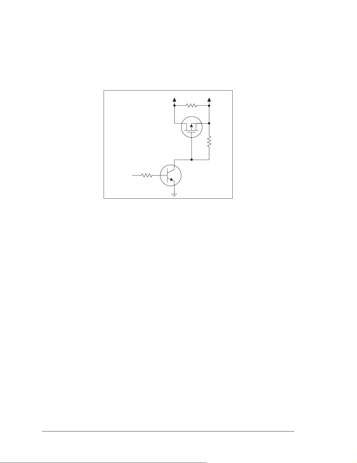
C.2.3 Power to VRAM Switch
The VRAM switch, shown in Figure C-3, allows the battery backup to provide power
when the external power goes off. The switch provides an isolation between Vcc and the
battery when Vcc goes low. This prevents the Vcc line from draining the battery.
/RESET
R104
22 kW
VCC
Q9
FDV302P
Q8
MMBT3904
R99
0 W
VRAM
R93
11 kW
Figure C-3. VRAM Switch
Field-effect transistor Q9 is needed to provide a very small voltage drop between Vcc and
VRAM (<100 mV, typically 10 mV) so that the board components powered by Vcc will
not have a significantly different voltage than VRAM.
When the BL2000 is not in reset, the /RESET line will be high. This turns on Q8, causing
its collector to go low. This turns on Q9, allowing VRAM to nearly equal Vcc.
When the BL2000 is in reset, the /RESET line will go low. This turns off Q8 and Q9, providing an isolation between Vcc and VRAM.
74 Wildcat (BL2000)
Page 79
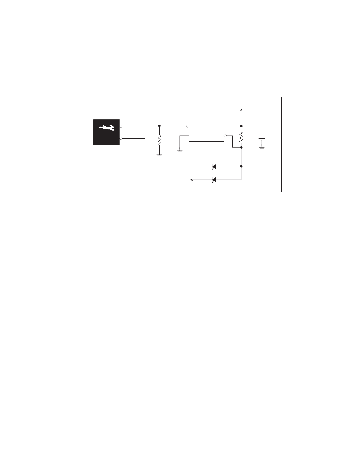
C.2.4 Reset Generator
The BL2000 uses a reset generator, U4, to reset the Rabbit 2000 mi croprocessor when the
voltage drops below the voltage necessary for reliable operation. The reset occurs between
4.50 V and 4.75 V, typically 4.63 V. The reset can be initiated either externally or by a
watchdog timeout (WDTOUT) on the Rabbit 2000 microprocessor.
+5 V
/RESET
WDTOUT
R151
100 kW
EXT
RESET
U4
RESET
GENERATOR
D15
D17
R69
22 kW
C24
100 nF
Figure C-4. Reset Generator
NOTE: The Dynamic C f unction chkWDTO is not able to detect whether a watchdog
timeout has occurred on the BL2000. The GCSR status bits are read and stored by the
BIOS, and the reset status bit would normally change once a reset has occurred. However, sin ce WDTOUT is tied to the reset generator, a watchdog timeout forces a hard-
ware reset, followed by the BIOS reading and storing the status bits corresponding to
power-up or reset.
To use chkWDTO to detect a watchdog timeout, remove D15 (located on the bottom
side of the BL2000).
User’s Manual 75
Page 80
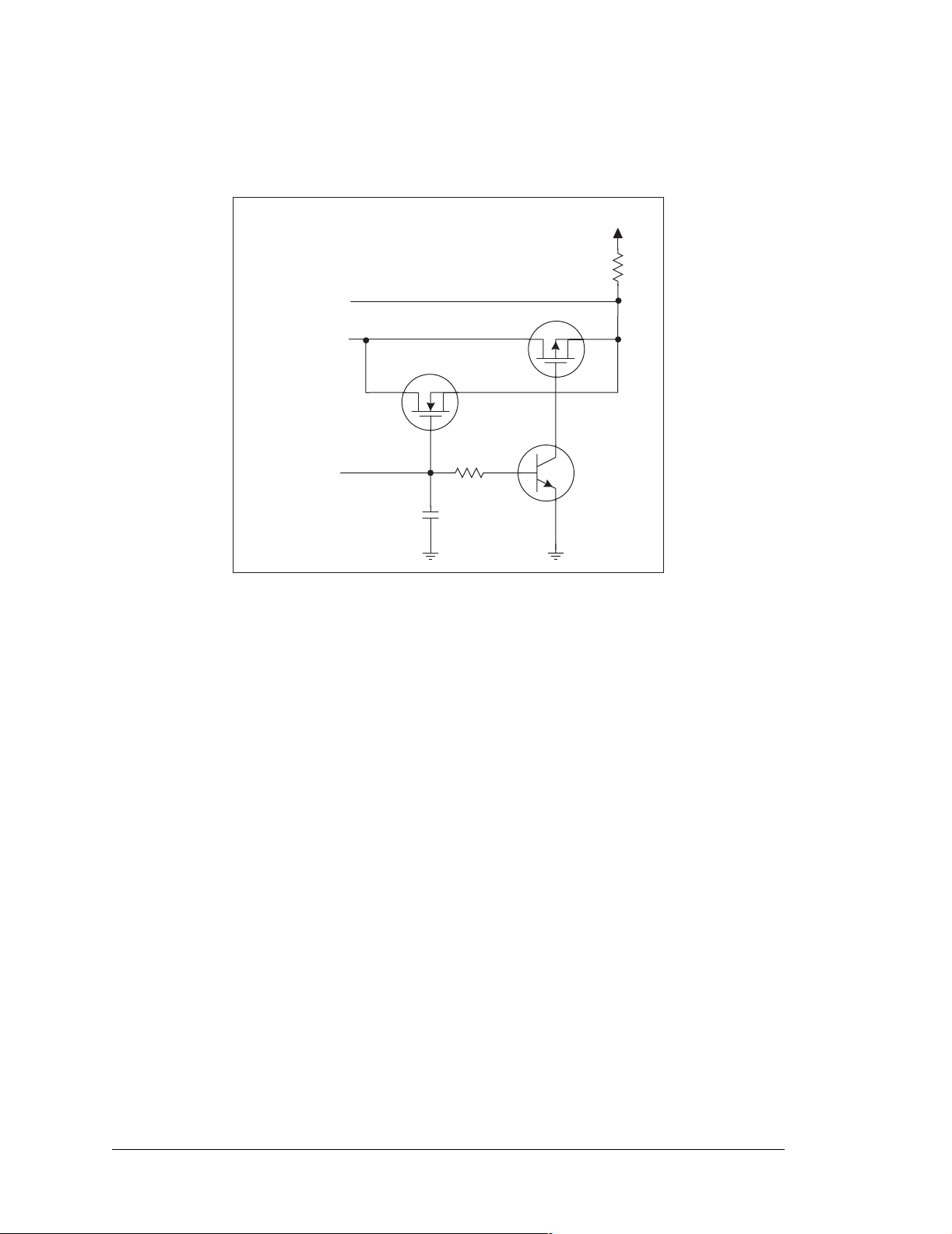
C.3 Chip Select Circuit
Figure C-5 shows a schematic of the chip select circuit.
R101
100 kW
VRAM
/CSRAM
/CS1
Q4
R104
/RESET
22 kW
C81
1 nF
Figure C-5. Chip Select Circuit
Q3
Q8
The current drain on the battery in a battery-backed circuit must be kept at a minimum.
When the BL2000 is not powered, the battery keeps the SRAM memory contents and the
real-time clock (RTC) going. The SRAM has a powerdown mode that greatly reduces
power consumption. This powerdown mode is activated by raising the chip select (CS)
signal line. Normally the SRAM requires Vcc to operate. However, only 2 V is required
for data retention in powerdown mode. Thus, when power is removed from the circuit, the
battery voltage needs to be provided to both the SRAM power pin and to the CS signal
line. The CS control circuit accomplishes this task for the SRAM’s chip select signal line.
In a powered-up condition, the CS control circuit must allow the processor’s chip select
signal /CS1 to control the SRAM’ s CS signal /CSR AM. So, with power applied, /CSRAM
must be the same signal as /CS1, and with power removed, /CSRAM must be held high
(but only needs to be battery voltage high). Q3 and Q4 are MOSFET transistors with complementary polarity. They are both turned on when power is applied to the circuit. They
allow the CS signal to pass from the processor to the SRAM s o that the proc essor can per iodically access the SRAM. When power is removed from the circuit, the transistors will
turn off and isolate /CSRAM from the processor. The isolated /CSRAM line has a 100 kΩ
pullup resistor to VRAM (R101). This pullup resistor keeps /CSRAM at the VRAM voltage level (which under no power condition is the backup battery’s regulated voltage at a
little more than 2 V).
76 Wildcat (BL2000)
Page 81

Transistors Q3 and Q4 are of opposite polarity so that a rail-to-rail voltage can be passed.
When the /CS1 voltage is low, Q4 will conduct. When the /CS1 voltage is high, Q3 conducts. It takes time for the transistors to turn on, creating a propagation delay. This propagation delay is typically very small, about 10 ns to 15 ns.
The signal that turns the transistors on is a high on the processor’s reset line,
/RESET.
When the BL2000 is not in reset, the reset line will be high, turning on n-channel Q4
directly and p-channel FET Q3 by way of Q8. When the board is in reset both Q3 and Q4
are off, isolating /CSRAM and allowing it to be pulled to VRAM.
User’s Manual 77
Page 82

78 Wildcat (BL2000)
Page 83

APPENDIX D.
DEMONSTRATION BOARD
Appendix D shows how t o connect the Demonstration Board to
the BL2000.
D.1 Connecting Demonstration Board
Before running sample programs based on the Demonstration Board, you will have to connect the Demonstration Board
follows.
from the BL2000 Tool Kit to the BL2000 board. Proceed as
1. Use the wires included in the
tion
Board to header J8 and J9 on the BL2000. The connections are shown in Figure D-1
for sample programs DIGIN.C, DIGOUT.C, and SMTP.C, and in
program ANADIGIN.C.
2. Make sure that your BL2000 is connected to your PC and that the power supply is connected to the BL2000 and plugged in as described in Chapter 2, “Getting Started.”
BL2000 Tool
Kit to connect header J1 on the Demonstra-
Figure D-2
for sample
User’s Manual 79
Page 84
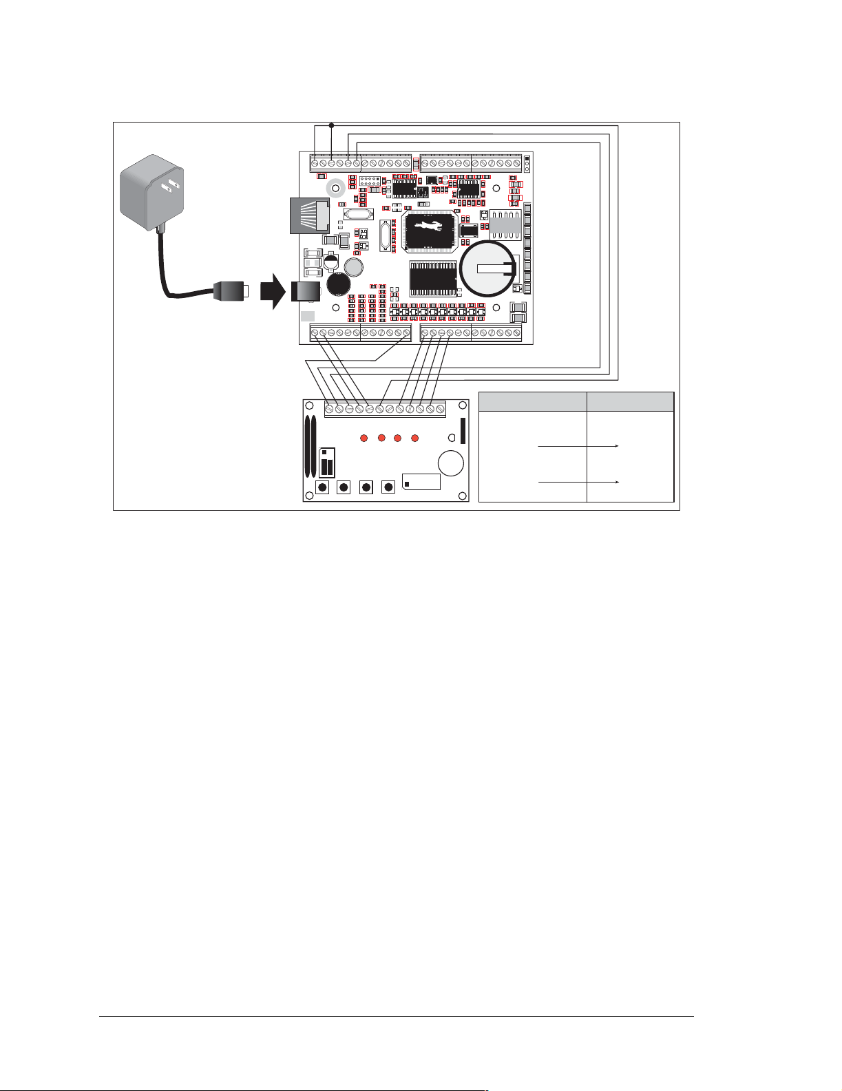
12 V DC max.
GND GND
C80
R130
Y3
R31
C35
R38
R52
C40
R56
R60
C85
J4
J3
AGND
AGND
AGND
C2
C3
C75
R5
R2
C79
R13
C1
R9
R15
C19
Y2
C36
R39
C41R53
R57
R61
U2
C8
R7
C4
R157
R10
R11
C11
JP1
R17
U1
R153
R154
U5
R27C22
R28
C27
R32
R34
R35
R40
D3
C43
GNDGNDGNDGND
C13
C18
JP2
C76
R152
65
90
40
15
C26
U6
R41
R42
D4
D5
C44
C45
GND
R43 R44
D6
C46
R45
D7 D8 D9
C47
GND
R47
R46
D10
C50
C49C48
GND
GND RST- IN1 IN0 485- 485+ RXD2 TXD2 RXD1 TXD1 AGND DAC1 DAC0 ADC8ADC7 ADC6 ADC5 ADC4 ADC3 ADC2 ADC1ADC0+RAW +K
J1
J2
GND
GN D
GND GND
R1
J6
C23
D1
TVS1
D2
J7
POWER IN
GND
J8
J10
IN3IN2 IN4 IN5 IN6 IN7 IN8 IN9 IN10 OUT8 OUT9 GND GNDOUT0 OUT1OUT2 OUT3 OUT4 OUT5 OUT6OUT7 NC
R4
R6
C10
R20
C20
C16
C17
C24
R151
C25
C28
+
14
23
J5
R12
R16
R19
U4
Q2
R30
C29
+
C31
L1
R33
C34
C33
R36
R37
R51
C38R50
C39
R55
R54
R59
R58
GN D
R22
C21
C32
C78
1432
AG ND
C14
Q5
R48
D11 D12
C51
GN D
R3
R23
C77
R24
Y1
R25
R29
D
Q3
Battery
R49
C52
AGND
R8
R18
Q1
R26
G
GND
C5
U3
C15
Q4
NO
AGND
C7
R21
56
S
GND
COM
+
K1
BT1
Q6
J12
C9
R14
C12
DS1
1
10
DS4DS3DS2
DS5
DS6
+
DS7
+
DS8
C37
C42
GND
J11
J9
PWRLNKACTOUT 0OUT 1OUT 2OUT 3BAD
BL2000
Jumpers:
H1: None
H2: As shown
·
·
·
·
·
GND
H2
· · 1-2
· · 3-4
· · 5-6
SW4
SW3
SW2
SW1
LED1 LED2 LED3 LED4
DEMO BOARD
+5V
SW1 SW2 SW3 SW4
· K·
LED1
· · 2-1
LED2
BUZZER
LED4
LED3
BUZZER
· · 8-7
· · 6-5
· ·
H1
J1
·
·
·
·
·
4-3
BL2000
(Header J2/J8/J9)
+RAW, K
GND
IN0
IN1
IN2
IN3
OUT0
OUT1
OUT2
OUT3
Demonstration Board
(Header J1)
+5V
GND
SW1
SW2
SW3
SW4
LED1
LED2
LED3
LED4
Figure D-1. General Digital Connections Between BL2000 and Demonstration Board
80 Wildcat (BL2000)
Page 85
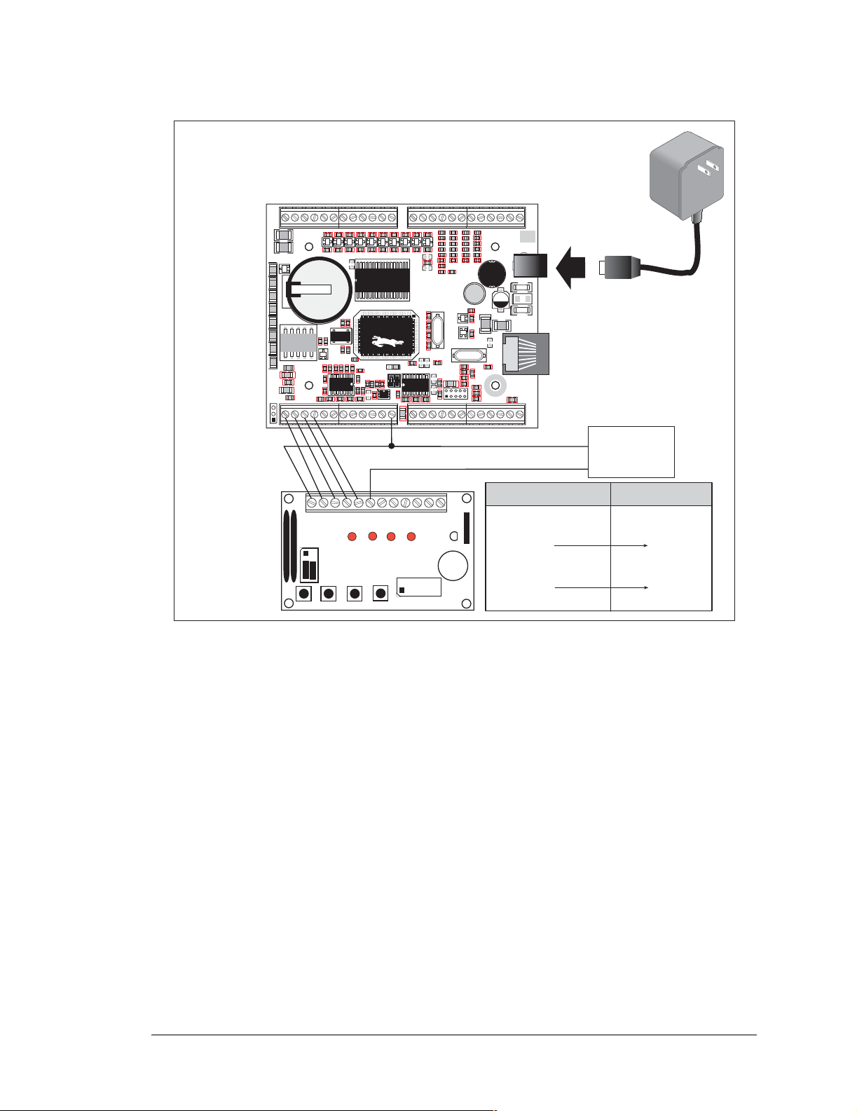
BL2000
COM
NO
J9
J11
GND
GND
GND
GN D
GND
C49C48
C52
C51
C50
GND
GND
C45
C44
C46
C47
C42
D5
D6
D7 D8 D9
D10
R21
C7
AGND
G
S
Q4
R25
R26
56
Q1
C15
R18
U3
R8
C5
AGND
R49
Battery
Q3
D
R29
Y1
R24
C77
R23
R3
D11 D12
R46
R45
R47
R48
C32
Q5
U6
C26
1432
40
C21
R22
R152
C14
C76
C13
R17
C11
R11
C4
R7
C78
R2
C79
R5
AGND
AG ND
C37
Q6
DS8
+
DS7
+
DS6
BT1
DS5
K1
DS4
10
DS3DS2
1
PWRLNKACTOUT 0OUT 1OUT 2OUT 3BAD
DS1
C12
R14
C9
+
J12
D4
R43 R44
R42
R41
C27
15
R28
90
R27C22
65
U5
JP2
C18
R154
U1
JP1
R10
R157
C8
U2
C75
C3
C2
AGND
AGND
J3
J4
C85
GN D
GNDGNDGNDGND
C43
R61
R59
R60
R55
R56
R57
C41R53
C40
C39
R52
R51
R38
R39
R37
C35
C36
C34
R33
D3
R31
C31
R40
R35
R34
R32
C29
R30
Q2
U4
Y2
Y3
C19
R153
R19
R15
R16
R130
C80
R9
C1
R13
J5
GND GND
GN D
IN3IN2 IN4 IN5 IN6 IN7 IN8 IN9 IN10 OUT8 OUT9 GND GNDOUT0 OUT1 OUT2 OUT3 OUT4 OUT5 OUT6 OUT7 NC
J10
J8
R151
C16
C24
C17
C20
R20
C10
R6
R4
GND
23
14
+
C28
C25
GND
POWER IN
J7
D2
TVS1
12 V DC max.
D1
C23
J6
R1
GND GND
J2
J1
GND RST- IN1 IN0 485- 485+ RXD2 TXD2 RXD1 TXD1 AGND DAC1 DAC0 ADC8ADC7 ADC6 ADC5 ADC4 ADC3 ADC2 ADC1 ADC0+RAW +K
GND
EXTERNAL
POWER SUPPLY
+5 V
R58
R54
C38R50
R36
C33
L1
+
R12
Jumpers:
H1: None
H2: As shown
·
·
·
·
·
+5V
SW4
SW3
SW2
SW1
GND
H2
LED1 LED2 LED3 LED4
· · 1-2
· · 3-4
DEMO BOARD
· · 5-6
SW1 SW2 SW3 SW4
J1
·
·
·
·
·
· K·
BUZZER
LED4
LED3
LED2
LED1
BUZZER
· · 8-7
· · 6-5
· ·
· · 2-1
H1
4-3
BL2000
(Header J4)
Separate Power Supply
GND
ADC0
ADC1
ADC2
ADC3
N/C
N/C
N/C
N/C
Demonstration Board
(Header J1)
+5V
GND
SW1
SW2
SW3
SW4
LED1
LED2
LED3
LED4
Figure D-2. Analog Connections Between BL2000 and Demonstration Board
User’s Manual 81
Page 86

82 Wildcat (BL2000)
Page 87

APPENDIX E. PROGRAMMING CABLE
Appendix E provides additional information for the programming port in association with the
DIAG and PROG connectors
on the programming cable. The
when the programming cable is attached to the programming
connector (header J5) while a new application is being developed. Otherwise, the
allows the programming cable to be used as an RS-232 to
CMOS level converter for serial communication, which is
appropriate for monitoring or debugging a BL2000 system
while it is running.
DIAG connector on t he p rog r am mi ng ca bl e
PROG connector is used only
User’s Manual 83
Page 88
The programming port, which is shown in Figure E-1, can serve as a convenient communications port for field setup or other occasional communication need (for example, as a
diagnostic port). If the port is simply to perform a setup function, that is, write setup information to flash memory, then the single-board computer can be reset through the programming port and a cold boot performed to start execution of a special program dedicated to
this functionality.
PROGRAMMING PORT PIN ASSIGNMENTS
12
34
56
78
9
Programming Port
Pin Numbers
10
(Rabbit PQFP pins are shown in parenthesis)
1. RXA (51)
2. GND
3. CKLKA (94)
4. +5 V/+3 V
5. /RESET
6. TXA (54)
7. n.c.
8. STATUS (output) (38)
9. SMODE0 (36)
10. SMODE1 (35)
~50 kW
~50 kW
~10 kW
~50 kW
~50 kW
+
+
+
GND
GND
Figure E-1. Programming Port Pin Assignments
When the PROG connector is used, the /RESET line can be asserted by manipulating
DTR and the STATUS line can be read as DSR on the serial port. The target can be
restarted by pulsing reset and then, after a short delay, sending a special character string at
2400 bps. To simply restart the BIOS, the string 80h, 24h, 80h can be sent. When the
BIOS is started, it can tell whether the programming cable is connected because the
SMODE1 and SMODE0 pins are sensed as being high.
Alternatively, the DIAG connector can be used to connect the programming port. The
/RESET line and the SMODE1 and SMODE0 pins are not connected to this connector.
The programming port is then enabled as a diagnostic port by polling the port periodically
to see if communication needs to begin or to enable the port and wait for interrupts. The
pull-up resistors on RXA and CLKA prevent spurious data reception that might take place
if the pins floated.
If the clocked serial mode is used, the serial port can be driven by having two toggling
lines that can be driven and one line that can be sensed. This allows a conversation with a
device that does not have an asynchronous serial port but that has two output signal lines
and one input signal line.
The line TXA (also called PC6) is zero after reset if the cold-boot mode is not enabled. A
possible way to detect the presence of a cable on the programming port is for the cable to
connect TXA to one of the SMODE pins and then test for the connection by raising PC6
(by configuring it as a general output bit) and reading the SMODE pin after the cold-boot
mode has been disabled. The value of the SMODE pin is read from the SPCR register.
84 Wildcat (BL2000)
Page 89

Once you establish that the programming port will never again be needed for programming, it is possible to use the programming port for additional I/O lines. Table E-1 lists the
pins available for this alternate configuration.
Table E-1. BL2000 Programming Port Pinout Configu rations
Pin Pin Name Default Use Alternate Use Notes
1 RXA Serial Port A PC6—Input
2GND
3CLKA
4VCC
5 RESET
6 TXA Serial Port A PC7—Output
8 STATUS Output
9 SMODE0 Input
10 SMODE1 Input
PB1—Bitwise or parallel
programmable input
Connected to reset
generator U4
Must be low when
BL2000 boots up
Must be low when
BL2000 boots up
User’s Manual 85
Page 90

86 Wildcat (BL2000)
Page 91

NOTICE TO USERS
Z-WORLD PRODUCTS ARE NOT AUTHORIZED FOR USE AS CRITICAL COMPONENTS IN LIFESUPPORT DEVICES OR SYSTEMS UNLESS A SPECIFIC WRITTEN AGREEMENT REGARDING
SUCH INTENDED USE IS ENTERED INTO BETWEEN THE CUSTOMER AND Z-WORLD PRIOR
TO USE. Life-support devices or systems are devices or systems intended for surgical implantation into the
body or to sustain life, and whose failure to perfo rm, when pro perly used in accor dance with instructions for
use provided in the labeling and user’s manual, can be reasonably expected to result in significant injury.
No complex software or hardware system is perfect. Bugs are always present in a system of any size. In
order to prevent danger to life or property, it is the responsibility of the system designer to incorporate
redundant protective mechanisms appropriate to the risk involved.
All Z-World products are 100 percent functionally tested. Additional testing may include visual quality control inspections or mechanical defects analyzer inspections. Specifications are based on characterization of
tested sample units rather than testing over temperature and voltage of each unit. Z-World products may
qualify components to operate within a range of parameters that is different from the manufacturer’s recommended range. This strategy is believed to be more economical and effective. Additional testing or burn-in
of an individual unit is available by special arrangement.
User’s Manual 87
Page 92

88 Wildcat (BL2000)
Page 93

INDEX
A
A/D converter inputs .............26
analog I/O
reference voltages .............27
analog inputs
use as digital inputs ........... 26
analog outputs ....................... 27
B
battery
connections .......................72
life ..................................... 72
replacing the backup bat-
tery ................................73
C
CE compliance ........................5
design guidelines .................6
chip select circuit .................. 76
clock doubler ........................31
conformal coating ................. 64
connections
battery ............................... 72
Ethernet cable ................... 51
D
D/A converter outputs ...........27
Demonstration Board ..............3
hookup instructions ........... 79
analog sample programs 81
digital sample programs 80
wire assembly .....................3
digital inputs .........................16
configured pull-up or pull-
down .............................16
dual-purpose A/D converter
inputs as digital inputs ..17
switching threshold ...........17
digital outputs .......................18
+K ..................................... 18
pulled up or pulled down .. 18
sinking ...............................18
sourcing .............................18
dimensions
BL2000 board ................... 58
plastic enclosure ................70
Dynamic C ........................4, 33
add-on modules .................34
basic instructions ...............33
COM port ..........................10
debugging features ............ 33
installation ........................... 9
starting .............................. 10
telephone-based technical
support ...................... 4, 34
upgrades and patches ........34
E
EMI
spectrum spreader feature . 31
Ethernet cables ......................51
Ethernet connections .............51
steps .................................. 51
Ethernet port .........................24
ground lug .........................25
handling EMI and noise .... 24
pinout ................................ 24
external interrupts ................. 31
F
features ....................................1
flash memory
lifetime write cycles .......... 33
I
installation
plastic enclosure
BL2000 .........................68
light pipes ...................... 68
top ................................. 69
IP addresses ..........................54
how to set ..........................53
how to set PC IP address .. 54
J
jumper configurations ..... 63, 64
J9(12) ................................ 71
J9(12) is GND ................... 64
J9(12) is Vcc ..................... 64
JP1 (RS-485 bias and termin a-
tion resistors) .......... 23, 64
JP2 (flash memory bank
select) ......................29, 64
JP3 (D/A converter power
supply) .................... 27, 64
JP4 (flash memory size) 29, 64
JP5 (SRAM size) ........ 29, 64
JP6 (digital input pull-up/pull-
down resistors) ....... 16, 64
jumper locations ................63
K
K ........................................... 18
M
memory .................................29
flash memory configura-
tions ..............................29
SRAM configuration for
different sizes ...............29
models .....................................2
BL2000 ............................... 2
BL2010 ............................... 2
BL2020 ............................... 2
BL2030 ............................... 2
P
pin configurations
programming port ............. 85
pinout
BL2000 headers .......... 14, 15
Ethernet port ..................... 24
programming port ............. 84
User’s Manual 89
Page 94

plastic enclosure ................3, 68
attach BL2000 to base .........7
dimensions .........................70
power management ...............71
power supplies .......................71
backup-battery circuit ........73
battery backup ...................72
chip select circuit ...............76
switching voltage regulator 71
VRAM switch ...................74
power supply ...........................3
connections ....................8, 15
Program Mode .......................30
programming
flash vs. RAM ................... 33
programming cable ..............3
programming port ..............23
programming cable .................3
connections ..........................8
DIAG connector ................84
programming port
pin configurations ..............85
pinout .................................84
used as diagnostic port ...... 84
R
Rabbit 2000
parallel ports ......................65
relay outputs ..........................20
operation in parallel with
digital output OUT0 ......20
reset .........................................8
hardware ..............................8
reset generator ...................75
RS-232 ..................................21
RS-485 ..................................21
RS-485 network ....................22
termination and bias resistors
23
Run Mode ..............................30
S
sample programs ...................35
A/D converter inputs
AD_CALIB.C ................36
AD1.C ............................36
AD2.C ............................36
AD3.C ............................36
AD4.C ............................36
BOARD_ID.C ...................35
COUNTLEDS.C ...............35
D/A converter outputs
DACAL.C ......................37
DAOUT1.C ...................37
DAOUT2.C ...................37
digital I/O
ANADIGIN.C ...............35
DIGIN.C ........................35
DIGOUT.C ....................35
LED.C ............................35
PWM.C ..........................36
RELAY.C ......................36
how to set IP address .........53
LEDS_4.C .........................35
PONG.C ............................11
serial communication
MASTER.C ...................36
PUTS.C ..........................36
RELAYCHR.C ..............36
SLAVE.C ......................36
TCP/IP ............................... 53
PINGME.C ....................55
SMTP.C .........................56
SSI.C ..............................56
TELNET.C ....................56
serial communication ............21
programming port ..............23
RS-232 description ............21
RS-485 description ............21
RS-485 network ................22
RS-485 termination and bias
resistors .........................23
serial ports
Ethernet port ......................24
setup ........................................7
attach BL2000 to enclosure
base .................................7
power supply connecti ons ...8
programming cable connec-
tions ................................. 8
software ................................... 4
A/D converter inputs
_anaIn ............................44
anaIn ..............................45
anaInCalib .....................44
anaInEERd .....................46
anaInEEWr ....................46
anaInVolts .....................46
board initialization ............39
brdInit ............................39
D/A converter outputs
anaOut ...........................48
anaOutCalib ...................47
anaOutEERd ..................49
anaOutEEWr .................49
anaOutVolts ...................49
digital I/O
digIn ...............................41
digOut ............................41
LED outputs
ledOut ............................43
libraries .............................. 30
BL2000 ..........................38
PACKET.LIB ................42
RS232.LIB .....................42
TCP/IP ...........................38
relay output
relayOut .........................43
sample programs ............... 35
BOARD_ID.C ...............35
COUNTLEDS.C ............35
LEDS_4.C .....................35
PONG.C ........................11
serial communication
flow control ...................42
ser485Rx ........................42
ser485Tx ........................ 42
serCflowcontrolOff .......42
serCflowcontrolOn ........42
watchdog timeout
chkWDTO .....................75
specifications
BL2100
header footprint .............61
headers ...........................61
relative pin 1 locations ..61
dimensions
plastic enclosure ............70
dimensions BL2000 ..........58
electrical ............................59
temperature ........................59
spectrum spreader .................31
subsystems ......................13, 14
T
TCP/IP connections ...............51
10Base-T Ethernet card .....51
additional resources ...........56
Ethernet hub ......................51
steps ................................... 51
technical support ...................11
Tool Kit ...................................3
AC adapter ............... ...........3
DC power supply .................3
Demonstration Board ..........3
Dynamic C software ............3
plastic enclosure ..................3
programming cable ..............3
software ...............................3
User’s Manual .....................3
wire assembly ......................3
V
Vcc
J9(12) ................................. 71
90 Wildcat (BL2000)
Page 95

SCHEMATICS
090-0117 BL2000 Schematic
www.zworld.com/documentation/schemat/090-0117.pdf
090-0042 Demonstration Board Schematic
www.zworld.com/documentation/schemat/090-0042.pdf
090-0128 Programming Cable Schematic
www.zworld.com/documentation/schemat/090-0128.pdf
The schematics included with the printed manual were the la te st revisi ons availa ble at the
time the manual was last revised. The online versions of the manual contain links to the
latest revised schematic on the Web site. You may also use the URL information provided
above to access the latest schematics directly.
User’s Manual 91
Page 96

 Loading...