


M-1600
Table of contents
 Loading...
Zund M-1600, L-3200, L-2500, XL-3200, 2XL-1600 Operating Manual
...
Digital flatbed cutter
G3 series
(M-1600, M-2500, L-2500, L-3200, XL-1600, XL-3200, 2XL-1600, 2XL-3200, 3XL-1600, 3XL-3200)
Operating manual
EN

Original operating instructions
Author Technical Communications
Department, Zünd Systemtechnik AG
Composition and publication Zünd Systemtechnik AG
Copyright
©
Version:
Menu version:
Date:
Doc. no.:
Zünd Systemtechnik AG
09
1.45
05-2010
5106015

G3 series
0
Contents
1 Introduction . . . . . . . . . . . . . . . . . . . . . . . . . . . . . . . . . . . . . . . . . . . . . . . . . 1
1.1 Foreword . . . . . . . . . . . . . . . . . . . . . . . . . . . . . . . . . . . . . . . . . . . . . . . . . . . 1
1.2 Using the documentation . . . . . . . . . . . . . . . . . . . . . . . . . . . . . . . . . . . . . . 2
1.2.1 Structure of the operating manual . . . . . . . . . . . . . . . . . . . . . . . . . . . . . . . 2
1.2.2 Symbols . . . . . . . . . . . . . . . . . . . . . . . . . . . . . . . . . . . . . . . . . . . . . . . . . . . 3
1.3 Points to note when reading this operating manual . . . . . . . . . . . . . . . . . . 4
1.4 Care of the documentation . . . . . . . . . . . . . . . . . . . . . . . . . . . . . . . . . . . . . 4
1.5 Current status of documentation . . . . . . . . . . . . . . . . . . . . . . . . . . . . . . . . . 5
1.6 Standardisation, tests, marking . . . . . . . . . . . . . . . . . . . . . . . . . . . . . . . . . 5
1.6.1 Standards . . . . . . . . . . . . . . . . . . . . . . . . . . . . . . . . . . . . . . . . . . . . . . . . . . 5
1.6.2 CE marking . . . . . . . . . . . . . . . . . . . . . . . . . . . . . . . . . . . . . . . . . . . . . . . . . 5
1.6.3 UL testing . . . . . . . . . . . . . . . . . . . . . . . . . . . . . . . . . . . . . . . . . . . . . . . . . . 6
1.7 Legal notice . . . . . . . . . . . . . . . . . . . . . . . . . . . . . . . . . . . . . . . . . . . . . . . . 7
1.8 Troubleshooting, hints and tips . . . . . . . . . . . . . . . . . . . . . . . . . . . . . . . . . . 7
1.9 Documented cutter models . . . . . . . . . . . . . . . . . . . . . . . . . . . . . . . . . . . . . 7
1.10 Publishing details . . . . . . . . . . . . . . . . . . . . . . . . . . . . . . . . . . . . . . . . . . . . 7
2 Product description . . . . . . . . . . . . . . . . . . . . . . . . . . . . . . . . . . . . . . . . . . .1
2.1 General . . . . . . . . . . . . . . . . . . . . . . . . . . . . . . . . . . . . . . . . . . . . . . . . . . . . 1
2.2 Product identification . . . . . . . . . . . . . . . . . . . . . . . . . . . . . . . . . . . . . . . . . 2
2.2.1 Rating plate . . . . . . . . . . . . . . . . . . . . . . . . . . . . . . . . . . . . . . . . . . . . . . . . . 2
2.2.2 UL marking . . . . . . . . . . . . . . . . . . . . . . . . . . . . . . . . . . . . . . . . . . . . . . . . . 3
2.3 Intended use . . . . . . . . . . . . . . . . . . . . . . . . . . . . . . . . . . . . . . . . . . . . . . . . 3
2.4 Cutter - overview . . . . . . . . . . . . . . . . . . . . . . . . . . . . . . . . . . . . . . . . . . . . . 4
2.5 Modules, tools . . . . . . . . . . . . . . . . . . . . . . . . . . . . . . . . . . . . . . . . . . . . . . . 5
2.5.1 General . . . . . . . . . . . . . . . . . . . . . . . . . . . . . . . . . . . . . . . . . . . . . . . . . . . . 5
2.5.2 UM . . . . . . . . . . . . . . . . . . . . . . . . . . . . . . . . . . . . . . . . . . . . . . . . . . . . . . . 5
2.5.2.1
2.5.3 RM-A . . . . . . . . . . . . . . . . . . . . . . . . . . . . . . . . . . . . . . . . . . . . . . . . . . . . . . 7
2.5.4 PUM . . . . . . . . . . . . . . . . . . . . . . . . . . . . . . . . . . . . . . . . . . . . . . . . . . . . . . 7
2.5.5 MAM-S/D . . . . . . . . . . . . . . . . . . . . . . . . . . . . . . . . . . . . . . . . . . . . . . . . . . 8
2.6 Material handling, options . . . . . . . . . . . . . . . . . . . . . . . . . . . . . . . . . . . . . . 9
2.6.1 Laser pointer . . . . . . . . . . . . . . . . . . . . . . . . . . . . . . . . . . . . . . . . . . . . . . . . 9
2.6.2 ICC camera . . . . . . . . . . . . . . . . . . . . . . . . . . . . . . . . . . . . . . . . . . . . . . . . . 9
2.6.3 Cutter with static work surface . . . . . . . . . . . . . . . . . . . . . . . . . . . . . . . . . . 9
2.6.4 Cutter with conveyor . . . . . . . . . . . . . . . . . . . . . . . . . . . . . . . . . . . . . . . . . 10
2.6.5 Sheet feeder options . . . . . . . . . . . . . . . . . . . . . . . . . . . . . . . . . . . . . . . . . 10
2.6.6 Drip tray . . . . . . . . . . . . . . . . . . . . . . . . . . . . . . . . . . . . . . . . . . . . . . . . . . 11
2.7 Technical description . . . . . . . . . . . . . . . . . . . . . . . . . . . . . . . . . . . . . . . . 12
2.7.1 Complete machine . . . . . . . . . . . . . . . . . . . . . . . . . . . . . . . . . . . . . . . . . . 12
2.7.2 Schedule of work sequences . . . . . . . . . . . . . . . . . . . . . . . . . . . . . . . . . . 12
2.7.3 Complete machine . . . . . . . . . . . . . . . . . . . . . . . . . . . . . . . . . . . . . . . . . . 13
2.7.4 Movement system . . . . . . . . . . . . . . . . . . . . . . . . . . . . . . . . . . . . . . . . . . . 14
2.7.5 Processing materials . . . . . . . . . . . . . . . . . . . . . . . . . . . . . . . . . . . . . . . . 15
2.8 Technical information . . . . . . . . . . . . . . . . . . . . . . . . . . . . . . . . . . . . . . . . 16
2.8.1 Dimensions and weights . . . . . . . . . . . . . . . . . . . . . . . . . . . . . . . . . . . . . . 16
2.8.1.1
2.8.1.2
2.8.2 Electrical connection, power consumption . . . . . . . . . . . . . . . . . . . . . . . . 19
Tools for the UM
Basic device
. . . . . . . . . . . . . . . . . . . . . . . . . . . . . . . . . . . . . . . . . . . . . . . 16
Cutter extension
. . . . . . . . . . . . . . . . . . . . . . . . . . . . . . . . . . . . . . . . . . . . . 6
. . . . . . . . . . . . . . . . . . . . . . . . . . . . . . . . . . . . . . . . . . . . 18
000017,03,06-2009, jmu
0-1

0
G3 series
2.8.3 Environmental conditions . . . . . . . . . . . . . . . . . . . . . . . . . . . . . . . . . . . . . 19
2.8.4 Basic device compressed air . . . . . . . . . . . . . . . . . . . . . . . . . . . . . . . . . . 19
2.8.5 Control unit . . . . . . . . . . . . . . . . . . . . . . . . . . . . . . . . . . . . . . . . . . . . . . . . 20
2.8.6 Performance . . . . . . . . . . . . . . . . . . . . . . . . . . . . . . . . . . . . . . . . . . . . . . . 21
2.8.7 Emissions . . . . . . . . . . . . . . . . . . . . . . . . . . . . . . . . . . . . . . . . . . . . . . . . . 22
2.8.8 FCC approval . . . . . . . . . . . . . . . . . . . . . . . . . . . . . . . . . . . . . . . . . . . . . . 22
3 Safety . . . . . . . . . . . . . . . . . . . . . . . . . . . . . . . . . . . . . . . . . . . . . . . . . . . . .1
3.1 General . . . . . . . . . . . . . . . . . . . . . . . . . . . . . . . . . . . . . . . . . . . . . . . . . . . . 1
3.2 Proper use . . . . . . . . . . . . . . . . . . . . . . . . . . . . . . . . . . . . . . . . . . . . . . . . . 2
3.3 Examples of improper use . . . . . . . . . . . . . . . . . . . . . . . . . . . . . . . . . . . . . 2
3.4 Hazard warnings, important instructions . . . . . . . . . . . . . . . . . . . . . . . . . . . 3
3.4.1 Explanation of the hazard warning . . . . . . . . . . . . . . . . . . . . . . . . . . . . . . . 3
3.4.2 Structure of the hazard warnings . . . . . . . . . . . . . . . . . . . . . . . . . . . . . . . . 4
3.5 Areas of responsibility . . . . . . . . . . . . . . . . . . . . . . . . . . . . . . . . . . . . . . . . . 5
3.6 Personnel requirements . . . . . . . . . . . . . . . . . . . . . . . . . . . . . . . . . . . . . . . 5
3.7 Rules and safety at work . . . . . . . . . . . . . . . . . . . . . . . . . . . . . . . . . . . . . . . 6
3.8 Procedure in case of malfunctions . . . . . . . . . . . . . . . . . . . . . . . . . . . . . . . 6
3.9 Danger areas . . . . . . . . . . . . . . . . . . . . . . . . . . . . . . . . . . . . . . . . . . . . . . . 7
3.9.1 General danger area . . . . . . . . . . . . . . . . . . . . . . . . . . . . . . . . . . . . . . . . . . 7
3.9.2 Danger area on the module carriage . . . . . . . . . . . . . . . . . . . . . . . . . . . . . 8
3.9.3 Danger area during the installation . . . . . . . . . . . . . . . . . . . . . . . . . . . . . . . 9
3.10 Working and traffic area . . . . . . . . . . . . . . . . . . . . . . . . . . . . . . . . . . . . . . 10
3.11 Safety signs . . . . . . . . . . . . . . . . . . . . . . . . . . . . . . . . . . . . . . . . . . . . . . . 11
3.11.1 Responsibility of the operator . . . . . . . . . . . . . . . . . . . . . . . . . . . . . . . . . . 11
3.11.2 Position of the safety signs . . . . . . . . . . . . . . . . . . . . . . . . . . . . . . . . . . . . 11
3.12 Safety and monitoring devices . . . . . . . . . . . . . . . . . . . . . . . . . . . . . . . . . 14
3.12.1 Protective system . . . . . . . . . . . . . . . . . . . . . . . . . . . . . . . . . . . . . . . . . . . 15
3.12.2 Operating unit . . . . . . . . . . . . . . . . . . . . . . . . . . . . . . . . . . . . . . . . . . . . . . 15
3.12.3 Emergency stop switch . . . . . . . . . . . . . . . . . . . . . . . . . . . . . . . . . . . . . . . 16
3.12.4 Safety cut-off feature . . . . . . . . . . . . . . . . . . . . . . . . . . . . . . . . . . . . . . . . . 16
3.13 Personal protective equipment, clothing . . . . . . . . . . . . . . . . . . . . . . . . . . 17
3.14 Mechanical hazards . . . . . . . . . . . . . . . . . . . . . .
3.14.1 Gathering, retraction . . . . . . . . . . . . . . . . . . . . . . . . . . . . . . . . . . . . . . . . . 18
3.14.2 Gathering, impacts of foreign objects . . . . . . . . . . . . . . . . . . . . . . . . . . . . 18
3.14.3 Cuts and stab wounds . . . . . . . . . . . . . . . . . . . . . . . . . . . . . . . . . . . . . . . 19
3.15 Risk of burns . . . . . . . . . . . . . . . . . . . . . . . . . . . . . . . . . . . . . . . . . . . . . . . 19
3.16 Electrical hazard . . . . . . . . . . . . . . . . . . . . . . . . . . . . . . . . . . . . . . . . . . . . 20
3.17 Risks arising from the emission of toxic dust . . . . . . . . . . . . . . . . . . . . . . 21
3.18 Risks arising from the processing of toxic/hazardous materials . . . . . . . . 21
3.19 Environmental hazard . . . . . . . . . . . . . . . . . . . . . . . . . . . . . . . . . . . . . . . . 22
3.20 Handling and storage of chemicals . . . . . . . . . . . . . . . . . . . . . . . . . . . . . . 23
3.21 Risk of fire and explosion . . . . . . . . . . . . . . . . . . . . . . . . . . . . . . . . . . . . . 24
3.22 Danger caused by laser beam (laser pointer) . . . . . . . . . . . . . . . . . . . . . . 25
3.23 Safety instructions for operators . . . . . . . . . . . . . . . . . . . . . . . . . . . . . . . . 25
3.24 Safety precautions for service personnel . . . . . . . . . . . . . . . . . . . . . . . . . 26
3.25 Disposal . . . . . . . . . . . . . . . . . . . . . . . . . . . . . . . . . . . . . . . . . . . . . . . . . . 26
. . . . . . . . . . . . . . . . . . . 18
0-2
000017,03,06-2009, jmu

G3 series
4 Controls and operation . . . . . . . . . . . . . . . . . . . . . . . . . . . . . . . . . . . . . . . . 1
4.1 General . . . . . . . . . . . . . . . . . . . . . . . . . . . . . . . . . . . . . . . . . . . . . . . . . . . . 1
4.2 Safe working practices . . . . . . . . . . . . . . . . . . . . . . . . . . . . . . . . . . . . . . . . 1
4.3 Controls . . . . . . . . . . . . . . . . . . . . . . . . . . . . . . . . . . . . . . . . . . . . . . . . . . . 2
4.3.1 Control panel . . . . . . . . . . . . . . . . . . . . . . . . . . . . . . . . . . . . . . . . . . . . . . . 2
4.3.1.1
4.3.1.2
4.3.1.3
4.3.1.4
4.3.1.5
4.3.1.6
4.3.1.7
4.3.2 Emergency stop switches . . . . . . . . . . . . . . . . . . . . . . . . . . . . . . . . . . . . . . 7
4.3.3 Maintenance unit . . . . . . . . . . . . . . . . . . . . . . . . . . . . . . . . . . . . . . . . . . . . 9
4.3.4 Interfaces . . . . . . . . . . . . . . . . . . . . . . . . . . . . . . . . . . . . . . . . . . . . . . . . . 10
4.4 Menu navigation . . . . . . . . . . . . . . . . . . . . . . . . . . . . . . . . . . . . . . . . . . . . 11
4.4.1 Menus and functions . . . . . . . . . . . . . . . . . . . . . . . . . . . . . . . . . . . . . . . . . 11
4.4.2 Help . . . . . . . . . . . . . . . . . . . . . . . . . . . . . . . . . . . . . . . . . . . . . . . . . . . . . 13
4.4.3 Info menu . . . . . . . . . . . . . . . . . . . . . . . . . . . . . . . . . . . . . . . . . . . . . . . . . 13
4.4.4 Popups/dialogues . . . . . . . . . . . . . . . . . . . . . . . . . . . . . . . . . . . . . . . . . . . 13
4.4.5 User level . . . . . . . . . . . . . . . . . . . . . . . . . . . . . . . . . . . . . . . . . . . . . . . . . 14
4.4.6 Function keys . . . . . . . . . . . . . . . . . . . . . . . . . . . . . . . . . . . . . . . . . . . . . . 15
4.5 Functions . . . . . . . . . . . . . . . . . . . . . . . . . . . . . . . . . . . . . . . . . . . . . . . . . 16
4.5.1 Set language . . . . . . . . . . . . . . . . . . . . . . . . . . . . . . . . . . . . . . . . . . . . . . . 16
4.5.2 Set display . . . . . . . . . . . . . . . . . . . . . . . . . . . . . . . . . . . . . . . . . . . . . . . . 16
4.5.3 Setting the volume of the signal . . . . . . . . . . . . . . . . . . . . . . . . . . . . . . . . 16
4.5.4 Delete data buffer . . . . . . . . . . . . . . . . . . . . . . . . . . . . . . . . . . . . . . . . . . . 16
4.6 Operation . . . . . . . . . . . . . . . . . . . . . . . . . . . . . . . . . . . . . . . . . . . . . . . . . 17
4.6.1 Daily checks prior to start-up . . . . . . . . . . . . . . . . . . . . . . . . . . . . . . . . . . 17
4.6.2 Start-up . . . . . . . . . . . . . . . . . . . . . . . . . . . . . . . . . . . . . . . . . . . . . . . . . . . 18
4.6.3 Operating status . . . . . . . . . . . . . . . . . . . . . . . . . . . . . . . . . . . . . . . . . . . . 20
4.6.3.1
4.6.3.2
4.6.3.3
4.6.4 Moving the bar/module manually . . . . . . . . . . . . . . . . . . . . . . . . . . . . . . . 23
4.7 Handling modules/tools . . . . . . . . . . . . . . . . . . . . . . . . . . . . . . . . . . . . . . 24
4.7.1 Module/tool/tool insert . . . . . . . . . . . . . . . . . . . . . . . . . . . . . . . . . . . . . . . . 25
4.7.2 Set module/tool change position . . . . . . . . . . . . . . . . . . . . . . . . . . . . . . . . 26
4.7.3 Inserting/replacing the module . . . . . . . . . . . . . . . . . . . . . . . . . . . . . . . . . 27
4.7.3.1
4.7.3.2
4.7.4 Activating a module . . . . . . . . . . . . . . . . . . . . . . . . . . . . . . . . . . . . . . . . . 29
4.7.5 Tool handling . . . . . . . . . . . . . . . . . . . . . . . . . . . . . . . . . . . . . . . . . . . . . . 30
4.7.5.1
4.7.5.2
4.7.5.3
4.7.6 Attaching/selecting a tool . . . . . . . . . . . . . . . . . . . . . . . . . . . . . . . . . . . . . 32
4.7.6.1
4.7.6.2
4.7.6.3
Operating unit
Navigation keys
Numerical keys
Function keys
Travel keys
Soft keys
Special keys, shortcuts
OFFLINE
STOPPED
ONLINE
Module mount
Inserting/replacing the module (e.g. UM)
Marking the tool (e.g.)
Switching the tool manager on/off
. . . . . . . . . . . . . . . . . . . . . . . . . . . . . . . . . . . . . . . . . . . . . . . 3
. . . . . . . . . . . . . . . . . . . . . . . . . . . . . . . . . . . . . . . . . . . . . 4
. . . . . . . . . . . . . . . . . . . . . . . . . . . . . . . . . . . . . . . . . . . . . . 4
. . . . . . . . . . . . . . . . . . . . . . . . . . . . . . . . . . . . . . . . . . . . . . . 4
. . . . . . . . . . . . . . . . . . . . . . . . . . . . . . . . . . . . . . . . . . . . . . . . . 5
. . . . . . . . . . . . . . . . . . . . . . . . . . . . . . . . . . . . . . . . . . . . . . . . . . . 5
. . . . . . . . . . . . . . . . . . . . . . . . . . . . . . . . . . . . . . . . 6
. . . . . . . . . . . . . . . . . . . . . . . . . . . . . . . . . . . . . . . . . . . . . . . . . . 21
. . . . . . . . . . . . . . . . . . . . . . . . . . . . . . . . . . . . . . . . . . . . . . . . . 21
. . . . . . . . . . . . . . . . . . . . . . . . . . . . . . . . . . . . . . . . . . . . . . . . . . 22
. . . . . . . . . . . . . . . . . . . . . . . . . . . . . . . . . . . . . . . . . . . . . . 27
. . . . . . . . . . . . . . . . . . . . . . . . . 28
. . . . . . . . . . . . . . . . . . . . . . . . . . . . . . . . . . . . . . . . 30
. . . . . . . . . . . . . . . . . . . . . . . . . . . . . . 30
Tool manager — change tool (UM module)
Creating a new tool
Selecting a tool
Deleting a tool
. . . . . . . . . . . . . . . . . . . . . . . . . . . . . . . . . . . . . . . . . . 32
. . . . . . . . . . . . . . . . . . . . . . . . . . . . . . . . . . . . . . . . . . . . . 32
. . . . . . . . . . . . . . . . . . . . . . . . . . . . . . . . . . . . . . . . . . . . . . 32
. . . . . . . . . . . . . . . . . . . . . . . 31
0
000017,03,06-2009, jmu
0-3

0
G3 series
4.7.6.4
4.7.7 Inserting and connecting a tool (e.g. oscillating tool) . . . . . . . . . . . . . . . . 33
4.7.8 Connecting driven tools - allocating port . . . . . . . . . . . . . . . . . . . . . . . . . . 35
4.7.8.1
4.7.8.2
4.7.9 Tool positions . . . . . . . . . . . . . . . . . . . . . . . . . . . . . . . . . . . . . . . . . . . . . . 37
4.8 Material hold-down . . . . . . . . . . . . . . . . . . . . . . . . . . . . . . . . . . . . . . . . . . 38
4.8.1 Preparation . . . . . . . . . . . . . . . . . . . . . . . . . . . . . . . . . . . . . . . . . . . . . . . . 39
4.8.2 Defining/checking the vacuum range . . . . . . . . . . . . . . . . . . . . . . . . . . . . 40
4.8.3 Setting the strength . . . . . . . . . . . . . . . . . . . . . . . . . . . . . . . . . . . . . . . . . . 41
4.8.4 Switching on/off . . . . . . . . . . . . . . . . . . . . . . . . . . . . . . . . . . . . . . . . . . . . . 41
4.8.5 Working with air-permeable materials . . . . . . . . . . . . . . . . . . . . . . . . . . . . 41
4.9 Feeding options* . . . . . . . . . . . . . . . . . . . . . . . . . . . . . . . . . . . . . . . . . . . . 42
4.9.1 Feeding clamps . . . . . . . . . . . . . . . . . . . . . . . . . . . . . . . . . . . . . . . . . . . . . 43
4.9.2 Feed guide rail . . . . . . . . . . . . . . . . . . . . . . . . . . . . . . . . . . . . . . . . . . . . . 44
4.9.3 Feeding options . . . . . . . . . . . . . . . . . . . . . . . . . . . . . . . . . . . . . . . . . . . . 45
4.9.3.1
4.9.3.2
4.10 Automatic tool initialisation (AKI) . . . . . . . . . . . . . . . . . . . . . . . . . . . . . . . 46
4.10.1 Description . . . . . . . . . . . . . . . . . . . . . . . . . . . . . . . . . . . . . . . . . . . . . . . . 46
4.10.2 Adjusting the height . . . . . . . . . . . . . . . . . . . . . . . . . . . . . . . . . . . . . . . . . 47
4.10.3 Initialisation . . . . . . . . . . . . . . . . . . . . . . . . . . . . . . . . . . . . . . . . . . . . . . . . 48
4.11 Laser pointer, reference point . . . . . . . . . . . . . . . . . . . . . . . . . . . . . . . . . . 49
4.11.1 Laser pointer settings . . . . . . . . . . . . . . . . . . . . . . . . . . . . . . . . . . . . . . . . 49
4.11.2 Reference point settings . . . . . . . . . . . . . . . . . . . . . . . . . . . . . . . . . . . . . . 50
4.11.3 Choose laser pointer as pointer type . . . . . . . . . . . . . . . . . . . . . . . . . . . . 51
4.11.4 Define reference point . . . . . . . . . . . . . . . . . . . . . . . . . . . . . . . . . . . . . . . . 51
4.12 Material stop . . . . . . . . . . . . . . . . . . . . . . . . . . . . . . . . . . . . . . . . . . . . . . . 52
4.13 Module carriage slot protective plate . . . . . . . . . . . . . . . . . . . . . . . . . . . . 53
4.14 Module and tool holder* . . . . . . . . . . . . . . . . . . . . . . . . . . . . . . . . . . . . . . 54
4.15 Switch off the machine . . . . . . . . . . . . . . . . . . . . . . . . . . . . . . . . . . . . . . . 55
Saving tool-specific cutter settings
. . . . . . . . . . . . . . . . . . . . . . . . . . . . . . 32
Connection - electrical tools (EOT, DRT, etc.)
Connection - pneumatic tools
Automatic feed
Manual feed
. . . . . . . . . . . . . . . . . . . . . . . . . . . . . . . . . . . . . . . . . . . . . 45
. . . . . . . . . . . . . . . . . . . . . . . . . . . . . . . . . . . . . . . . . . . . . . . 45
. . . . . . . . . . . . . . . . . . . . . . . . . . . . . . . . . . 36
. . . . . . . . . . . . . . . . . . . . . 35
5 Description of menu . . . . . . . . . . . . . . . . . . . . . . . . . . . . . . . . . . . . . . . . . .1
5.1 General . . . . . . . . . . . . . . . . . . . . . . . . . . . . . . . . . . . . . . . . . . . . . . . . . . . . 1
5.2 Menu structure . . . . . . . . . . . . . . . . . . . . . . . . . . . . . . . . . . . . . . . . . . . . . . 1
5.3 Description of menu . . . . . . . . . . . . . . . . . . . . . . . . . . . . . . . . . . . . . . . . . . 2
6 Malfunctions . . . . . . . . . . . . . . . . . . . . . . . . . . . . . . . . . . . . . . . . . . . . . . . .1
6.1 Troubleshooting . . . . . . . . . . . . . . . . . . . . . . . . . . . . . . . . . . . . . . . . . . . . . 1
6.2 Locate error . . . . . . . . . . . . . . . . . . . . . . . . . . . . . . . . . . . . . . . . . . . . . . . . . 1
6.2.1 Error display . . . . . . . . . . . . . . . . . . . . . . . . . . . . . . . . . . . . . . . . . . . . . . . . 2
6.2.2 Error code . . . . . . . . . . . . . . . . . . . . . . . . . . . . . . . . . . . . . . . . . . . . . . . . . . 3
6.3 Error messages . . . . . . . . . . . . . . . . . . . . . . . . . . . . . . . . . . . . . . . . . . . . . . 4
0-4
000017,03,06-2009, jmu

G3 series
7 Cleaning and maintenance . . . . . . . . . . . . . . . . . . . . . . . . . . . . . . . . . . . . .1
7.1 General . . . . . . . . . . . . . . . . . . . . . . . . . . . . . . . . . . . . . . . . . . . . . . . . . . . . 1
7.2 Safe maintenance of the machine . . . . . . . . . . . . . . . . . . . . . . . . . . . . . . . 2
7.3 Operating resources . . . . . . . . . . . . . . . . . . . . . . . . . . . . . . . . . . . . . . . . . . 3
7.3.1 Handling operating materials . . . . . . . . . . . . . . . . . . . . . . . . . . . . . . . . . . . 3
7.3.2 Cleaning fluids . . . . . . . . . . . . . . . . . . . . . . . . . . . . . . . . . . . . . . . . . . . . . . 4
7.3.3 Lubricants . . . . . . . . . . . . . . . . . . . . . . . . . . . . . . . . . . . . . . . . . . . . . . . . . . 4
7.3.4 Adhesives . . . . . . . . . . . . . . . . . . . . . . . . . . . . . . . . . . . . . . . . . . . . . . . . . . 4
7.4 Steps for maintenance . . . . . . . . . . . . . . . . . . . . . . . . . . . . . . . . . . . . . . . . 5
7.5 Lubrication diagram . . . . . . . . . . . . . . . . . . . . . . . . . . . . . . . . . . . . . . . . . . 8
7.6 Accessories case . . . . . . . . . . . . . . . . . . . . . . . . . . . . . . . . . . . . . . . . . . . . 8
7.7 Maintenance jobs . . . . . . . . . . . . . . . . . . . . . . . . . . . . . . . . . . . . . . . . . . . 10
7.7.1 Service flaps and covers . . . . . . . . . . . . . . . . . . . . . . . . . . . . . . . . . . . . . . 10
7.7.2 Maintenance position . . . . . . . . . . . . . . . . . . . . . . . . . . . . . . . . . . . . . . . . 11
7.7.3 Visually inspect the machine for damage . . . . . . . . . . . . . . . . . . . . . . . . . 11
7.7.4 Clean the machine . . . . . . . . . . . . . . . . . . . . . . . . . . . . . . . . . . . . . . . . . . 12
7.7.5 Clean X axis guide rails . . . . . . . . . . . . . . . . . . . . . . . . . . . . . . . . . . . . . . 13
7.7.6 Oil X axis guide bearings . . . . . . . . . . . . . . . . . . . . . . . . . . . . . . . . . . . . . 15
7.7.7 Cleaning/oiling Y axis guide rails . . . . . . . . . . . . . . . . . . . . . . . . . . . . . . . 19
7.7.8 Lubricating the Y axis bearing . . . . . . . . . . . . . . . . . . . . . . . . . . . . . . . . . 21
7.7.9 Clean the chipping protection brush . . . . . . . . . . . . . . . . . . . . . . . . . . . . . 22
7.7.10 Cleaning the feeding clamps/feed guide rail . . . . . . . . . . . . . . . . . . . . . . . 23
7.7.11 Draining the maintenance unit condensation water . . . . . . . . . . . . . . . . . 24
7.7.12 Automatic circuit breakers . . . . . . . . . . . . . . . . . . . . . . . . . . . . . . . . . . . . 25
7.7.13 Conveyor belt . . . . . . . . . . . . . . . . . . . . . . . . . . . . . . . . . . . . . . . . . . . . . . 27
7.7.13.1
7.7.13.2
7.7.13.3
7.8 Instructions for disposal . . . . . . . . . . . . . . . . . . . . . . . . . . . . . . . . . . . . . . 36
7.9 Starting up after periods at a standstill . . . . . . . . . . . . . . . . . . . . . . . . . . . 36
7.9.1 Vacuum generator 1-9 KW/1-15 KW . . . . . . . . . . . . . . . . . . . . . . . . . . . . 36
Removing the conveyor belt
Removing the covers
Fitting a conveyor belt
. . . . . . . . . . . . . . . . . . . . . . . . . . . . . . . . . . . . . . . . 28
. . . . . . . . . . . . . . . . . . . . . . . . . . . . . . . . . . . . . . . 29
. . . . . . . . . . . . . . . . . . . . . . . . . . . . . . . . . . . 27
0
8 Tools . . . . . . . . . . . . . . . . . . . . . . . . . . . . . . . . . . . . . . . . . . . . . . . . . . . . . . 1
9 Modules . . . . . . . . . . . . . . . . . . . . . . . . . . . . . . . . . . . . . . . . . . . . . . . . . . . . 1
10 Options . . . . . . . . . . . . . . . . . . . . . . . . . . . . . . . . . . . . . . . . . . . . . . . . . . . . 1
11 Material handling . . . . . . . . . . . . . . . . . . . . . . . . . . . . . . . . . . . . . . . . . . . . .1
12 Additional specifications . . . . . . . . . . . . . . . . . . . . . . . . . . . . . . . . . . . . . . . 1
13 Documents . . . . . . . . . . . . . . . . . . . . . . . . . . . . . . . . . . . . . . . . . . . . . . . . . 1
14 Glossary . . . . . . . . . . . . . . . . . . . . . . . . . . . . . . . . . . . . . . . . . . . . . . . . . . . 1
000017,03,06-2009, jmu
0-5

0
G3 series
0-6
000017,03,06-2009, jmu

G3 series Introduction
Foreword
1 Introduction
Zünd Systemtechnik AG
Altstätten, Switzerland
1
1.1 Foreword
Dear customer,
By purchasing our product you are participating in the worldwide success of Zünd
cutter systems.
The modular design of our systems ensures:
• A system solution that is suited to your individual requirements in terms of speed
and quality
• The availability of the most up-to-date technology thanks to constant developments
Our approach
Constant and intensive cooperation with successful users is a prerequisite for
innovative and practical solutions. We are therefore grateful for any comments or
suggestions on how we can improve.
Contact
Zünd Systemtechnik AG Industriestrasse 8 CH - 9450 Altstätten
Tel. ++41 71-757 8181
Fax ++41 71-757 8191
Email
www zund.com
info@zund.com
000009,06,11-2009, jmu
1-1

1
Introduction G3 series
Using the documentation
1.2 Using the documentation
The instruction handbook supplied is intended to help you to:
– Operate the machine safely
– Perform routine machine maintenance
– Use the machine optimally in all permitted areas
To do this, you need to be able to find what you want within the documentation.
The instruction handbook comprises:
Volume 1 - Operating manual
This volume contains information on the engineering, installation, operation and
maintenance of the basic machine.
The technical documentation for the service personnel is contained in volumes 2 and
3:
Volume 2 - Service manual *
This volume contains information on the structure of the machine and on servicing
by authorised service personnel
Volume 3 - Spare parts catalogue * (See Zünd homepage)
1.2.1 Structure of the operating manual
The operating manual consists of individual, consecutively numbered chapters.
These sections are arranged according to the ring binder tabs.
The table of contents provides information on the structure of the individual chapters.
The numbers of pages and certain large graphics are prefixed with the number of the
relevant chapter. Page number "2-10", for example, means the tenth page of chapter
2 "Product description".
1-2
000009,06,11-2009, jmu

G3 series Introduction
Using the documentation
1.2.2 Symbols
Illustration
Close, fix, tighten, in
Open, release, loosen, out
Higher
1
Lower
Text structuring
Task: Steps to perform
Result: Outcome of the tasks performed.
Prerequisites for performing a task
List of tools
Optional accessories
There are a number of optional accessories available for the machine. Any
description relating to an optional accessory is identified in the operating manual by
the * symbol.
000009,06,11-2009, jmu
1-3

1
Introduction G3 series
Points to note when reading this operating manual
1.3 Points to note when reading this operating manual
Text references
Chapter headings are numbered consecutively, with the first figure corresponding to
the chapter number. Where reference is made to sections outside the current
chapter, note the first figure and turn to the corresponding chapter, which contains
the cited section. See chapter 2-4 "Overview of the machine", for example, leads to
chapter 2 "Product description", which contains section 4 "Overview of the machine".
Sketches and schematic representations
These are provided for general information and do not necessarily correspond to the
latest version of the machine.
Dimensional information
Dimensional information is listed in the SI/US unit system according to the place of
installation.
1.4 Care of the documentation
Volume 1 "Instruction manual" must always be kept in close vicinity of the
workstation.
Volume 2 "Service manual" must be made available to maintenance and service
personnel when required.
1-4
000009,06,11-2009, jmu

G3 series Introduction
Current status of documentation
1.5 Current status of documentation
Act accordingly to make sure that the documentation is complete and up-to-date at
all times:
– Do not remove parts of the documentation
– Request copies of missing or illegible pages from the manufacturer, or download
and print them from the Zünd homepage
– If any new documentation is delivered as a result of conversions taking place, file
it away immediately
– If documentation is changed, file the new information and destroy the old
– If the documentation exists in more than one language, ensure that all languages
are kept up-to-date
1.6 Standardisation, tests, marking
1.6.1 Standards
Scope of the documentation supplied
Volume 1: Operating manual
Volume 2: Service manual *
Volume 3: Spare parts catalogue *
1
Execution
This operating manual makes reference to the following standards:
• EN 62079
• EN 62023
• ANSI Z535-6
• EN ISO 12100-2
Important!
EU standards and guidelines which are applied are listed in the declaration of
conformity.
In the interests of our customers, we reserve the right to make changes as a result
of technical improvements. This document therefore corresponds to the technical
status of the product supplied and not the manufacturer's current state of
development.
1.6.2 CE marking
Within the EU, the cutter system is delivered with CE marking and an EC declaration
of conformity according to Annex II A of the EC Machinery Directive 2006/42/EC (see
chapter "Documents")
000009,06,11-2009, jmu
Important!
If the purchaser adds additional devices to the cutter system, or if the system is
integrated into an larger system then the device is supplied with a "Declaration for
the installation of an incomplete machine" according to Appendix II A of the EU
1-5

1
Introduction G3 series
Standardisation, tests, marking
Machinery Directive 2006/42/EC and/or without CE marking. As a result, the
declaration of conformity must be issued again by the purchaser.
1.6.3 UL testing
Zünd G3 cutters have been UL tested and comply with the ISO 60950 standard.
The certification can be accessed under UL number E176661.
1-6
000009,06,11-2009, jmu

G3 series Introduction
Legal notice
1.7 Legal notice
The information contained in this publication is intended for information purposes
only and is subject to change without notice at any time. This does not constitute an
obligation on the part of Zünd Systemtechnik AG.
No part of this document may be copied, distributed, used or disclosed to third parties
without express permission. Offenders will be liable for damages.
1.8 Troubleshooting, hints and tips
Important!
You can find information about troubleshooting and useful hints and tips on the Zünd
homepage. (www.zund.com)
1.9 Documented cutter models
This documentation applies for the following types of G3 series cutters.
1
G3 series
M line L line XL line 2XL line 3XL line
M-1600 L-3200 XL-3200 2XL-3200 3XL-3200
M-2500 L-2500
1.10 Publishing details
Name
Operating manual for G3 series cutters, side-support version.
Composition, illustration and publication
Zünd Systemtechnik AG - Technical Communications Department
©Copyright
Zünd Systemtechnik AG
XL-1600 2XL-1600 3XL-1600
000009,06,11-2009, jmu
1-7

1
Introduction G3 series
Publishing details
1-8
000009,06,11-2009, jmu
G3 series Product description
General
2 Product description
2.1 General
This chapter contains information on the following:
– Representational conventions in the operating manual
– Possible uses of the machine
– Structure of the main components
– Important technical data
– General technical description of the device
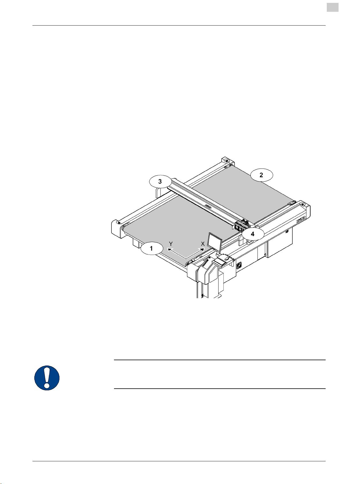
Directional information
Directions such as "right, left" or "forwards, backwards" are specified according to the
operator's view of the machine during operation.
2
000003,07,05-2010, jmu
Fig. 2-1 Directional information
1 Front 3 Left
2 Back 4 Right
Y Y axis X X axis
Important information
Important!
Refers to user tips and useful information which enhance the usability and prolong
the service life of the machine and make the work significantly easier.
2-1

2
Product description G3 series
Product identification
2.2 Product identification
2.2.1 Rating plate
Important!
The rating plate is used to uniquely identify your machine.
Fig. 2-2 Position of rating plate
1 Manufacturer
2 Product category
3 Device type
4 Serial number
1
see chapter "Introduction", "Standardisation, CE marking"
Structure of the serial number
Example:
Serial number Description
G3 Product
00L Bar length
25 Table length
0001 Consecutive device number
5 Year of manufacture
6 CE marking
7 Manufacturer's address
1
2-2
000003,07,05-2010, jmu

G3 series Product description
Intended use
2.2.2 UL marking
2
Fig. 2-3 UL marking
1 UL marking (Canada, USA)
2 Voltage range
2.3 Intended use
The cutter system can be used for the following purposes:
– As an output device for CAD/CAM data
– For processing and labelling materials arranged on the table
Aside from this, the intended use and the limits of the application are as follows:
– Depending on the tools and material feed system available,
– Described in the chapters "Tools", "Modules" and "Material transport".
3 Max. current
4 Frequency
000003,07,05-2010, jmu
2-3
2
Product description G3 series
Cutter - overview
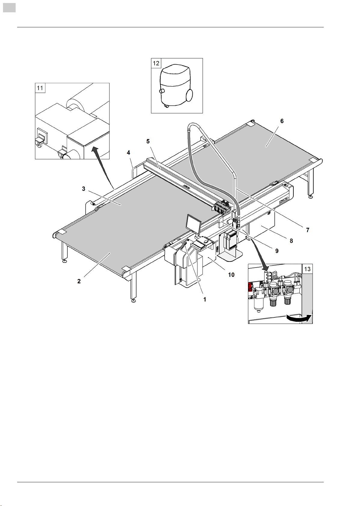
2.4 Cutter - overview
2-4
Fig. 2-4 Cutter - overview
1 Work station
2 Cutter extension, front
3 Table with vacuum
4 Left-hand safety device
5 Bar
6 Cutter extension, rear
7 Boom for router option
8 Power unit
9 Right-hand safety device
10 Electronics unit
11 Vacuum generator
12 Extractor (optional)
13 Maintenance unit (air pressure setting)
000003,07,05-2010, jmu

G3 series Product description
Modules, tools
2.5 Modules, tools
2.5.1 General
Modules
The use of modules and tool inserts means that Zünd
cutters can be highly specialised on the one hand,
whilst still being able to be easily converted for
processing other materials on the other hand.
As standard three modules can be fastened onto the
module carriage.
Instructions on the operation of your module can be
found in the chapter "Modules"/"Tool inserts".
Tools
Zünd offers tools for processing the most wide ranging
materials. A selection of important tool inserts can be
found under the corresponding module.
On the Zünd homepage (www.zund.com) you can find
Fig. 2-5 Modules - tool inserts - tools
1 1 Modules (UM/RM/PUM)
2 2 Tools (EOT/POT/DRT)
3 3 Module carriage
4 4 Router, blade, etc.
all the current tool inserts or contact your Zünd partner
for detailed information.
Instructions on the operation of your tool/module can
be found in the chapter "Modules"/"Tools".
2
2.5.2 UM
Tangentially controlled high-performance module for
the following tool inserts:
•POT
•EOT
• DRT
• Various insert sleeves and tool holders
000003,07,05-2010, jmu
2-5

2
Product description G3 series
Modules, tools
2.5.2.1 Tools for the UM
POT: Pneumatic oscillating tool for thick or tough
materials such as foam, filling materials, thick leather,
upholstery fabrics etc.
EOT: Electrical oscillating tool for cutting soft to
average toughness materials.
DRT: Driven tool for rotating knives for cutting textiles,
fibrous materials such as Kevlar, carbon
VCT: Cutting tool for producing V-cuts
UCT: Cutting tool which can be used universally
KCT: Cutting tool for foils with and without mount
material
UDT: Drawing tool
PPT: Passepartout (all-purpose) tool
2-6
000003,07,05-2010, jmu

G3 series Product description
Modules, tools
2.5.3 RM-A
Router module for the use of 1000 W Zünd motor
spindles.
2
2.5.4 PUM
Motor spindle with 1000 W for the processing of the
most wide-ranging materials.
Punching and stamping module for the processing of
leather materials.
000003,07,05-2010, jmu
2-7

2
Product description G3 series
Modules, tools
2.5.5 MAM-S/D
Single/double marking module for use of ballpoint pens
and other marking inserts.
2-8
000003,07,05-2010, jmu

G3 series Product description
Material handling, options
2.6 Material handling, options
2.6.1 Laser pointer
The laser pointer is used as an aid for the precise
definition of the reference point
2.6.2 ICC camera
2
The ICC camera is used as an aid for importing the
registration marks. The processing of the data is
dependent on the communication software.
2.6.3 Cutter with static work surface
The feeding and removal of the processing material
takes place on the work surface of the cutter. The work
surface is protected against damage using a cutting
base.
Fig. 2-6 Static work surface
000003,07,05-2010, jmu
2-9

2
Product description G3 series
Material handling, options
2.6.4 Cutter with conveyor
Conveyor systems are used for pulling the materials to
be worked with. The conveyor belt is used as a cutting
base and conveyor belt at the same time.
During the processing, the material to be processed is
fixed in place using a vacuum. After cutting, the bar
moves backwards. The conveyor clamping elements
fix the conveyor belt and the feeding clamps are
pressed onto the material to be pushed forward. The
bar tightens the conveyor belt to the set position.
The shape of the feeding clamps varies depending on
the material to be worked with. An auxiliary drive is
used in the case of larger tables or processing
Fig. 2-7 Conveyor
materials that are heavier for transportation.
Cutter extensions guarantee efficient work. The
material supply/removal is carried out while the cutter
is completing its jobs. These extensions are available
in different sizes, either with or without auxiliary drive.
Fig. 2-8 Cutter extension
2.6.5 Sheet feeder options
Fully-automatic sheet feeding
2-10
000003,07,05-2010, jmu

G3 series Product description
Material handling, options
2.6.6 Drip tray
Catches cutting waste
2
000003,07,05-2010, jmu
2-11
2
Product description G3 series
Technical description
2.7 Technical description
2.7.1 Complete machine
The G3 cutter is a variable processing system for flexible and rigid materials with
various tool systems. Extension options are available to provide improved handling
and for the adjustment of the system to special requirements or for processing
specific materials.
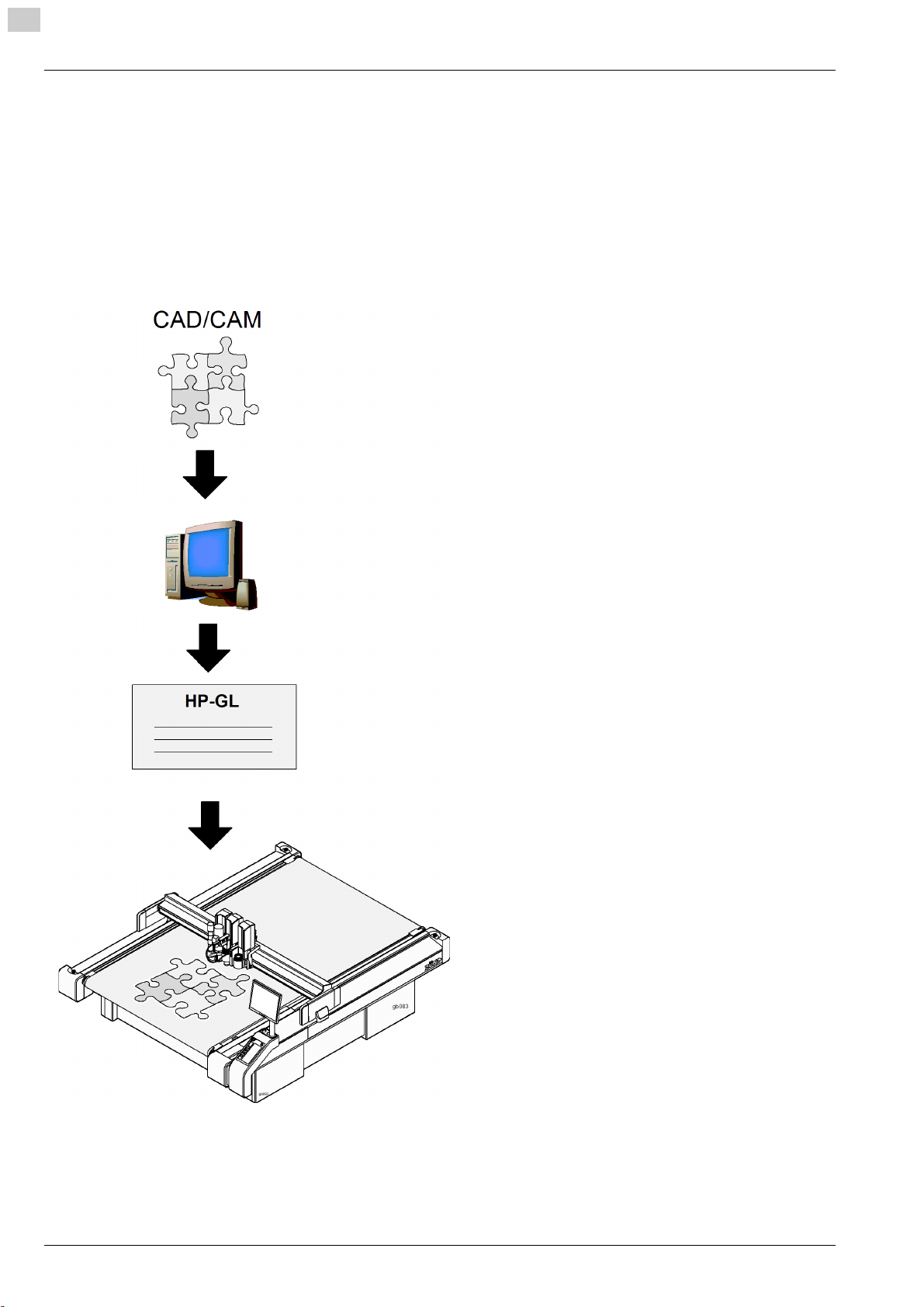
2.7.2 Schedule of work sequences
Starting point: CAD/CAM data
Communication software (e.g. ZCC)
Sending the HP-GL data to the cutter
Processing the sent data
2-12
000003,07,05-2010, jmu

G3 series Product description
Technical description
2.7.3 Complete machine
Table/vacuum plate
The work surface is designed as a perforated sheet. Vacuum zones are arranged
under this perforated sheet which are connected to a high-performance vacuum
generator via a distributor.
The vacuum is used for holding down and tightening the material to be processed.
The cutter control permits sequential activation/deactivation of the individual vacuum
zones and therefore reduces energy consumption. The vacuum generator (turbine
vacuum generator, vacuum pump) automatically regulates the vacuum strength (100
mBar).
Electronics unit
The electronics unit is housed in the front right-hand side of the cutter and is only
accessible for service personnel via a removable cover. The cutter control is housed
in the electronics unit.
Power unit
The power unit is housed in the rear right-hand side of the cutter and is only
accessible for service personnel via a removable cover. The power unit contains the
power supply of the complete cutter and is activated/deactivated using an on/off
switch. The connection of the individual consumers takes place using software
control if required.
2
Pneumatics
Air pressure and air flow are adjusted for the respective consumer via a maintenance
unit. The maintenance unit is accessible via a service door so that settings and
maintenance work can be carried out.
000003,07,05-2010, jmu
2-13

2
Product description G3 series
Technical description
2.7.4 Movement system
The G3 series has four electronically driven axes.
Axis Function Movement system
Bar Drive via toothed belt/steel belt
X
Material transport, material
transport extension
Y Movement of the module
carriage
Z Height adjustment of the
module
T Rotary movement of the
module
X axis - bar
The bar is driven by a motor via a toothed belt/gear mechanism and a toothed belt/
metal belt combination. The construction ensures that the function is backlash-free
and it also minimises wear on the drive system. The bar is supplied with control
signals and compressed air via an energy chain. All drive parts are protected against
direct access/contamination using covers.
Feed clamp elements, feeding
clamps, auxiliary drive
Drive via toothed belt/steel belt
Example: Universal module,
routing module
Example: Universal module
X axis - material transport
The material transport takes place via conveyor clamp elements and feed elements
on the bar, which move the conveyor belt including the material to be used via the
bar movement. In the case of large cutters, or cutters with material transport
extension, an auxiliary drive is also used.
Y axis - module carriage
The module carriage is driven by a motor via a toothed belt/gear mechanism and a
metal belt. The construction ensures that the function is backlash-free and it also
minimises wear on the drive system. The module carriage is supplied with control
signals and compressed air via an energy chain. All drive parts are protected against
direct access/contamination using covers.
Z axis - height adjustment of the module
Machine-controlled setting of the processing height (e.g. universal module)
T axis - rotary movement of the module
Modules with integrated T axis (e.g. universal module)
2-14
000003,07,05-2010, jmu
Loading...