

Page 1

WIP2
User’s Manual
Manual Part Number 90-18800
Zultys Technologies
771 Vaqueros Avenue
Sunnyvale CA 94085-5327
USA
+1-408-328-0450
http://www.zultys.com
Page 2

Notice
The information contained in this document is subject to change without notice.
Zultys Technologies makes no warranty of any kind with regard to this material, including, but
not limited to, the implied warranties of merchantability and fitness for a particular purpose.
Zultys Technologies shall not be liable for errors contained herein or for incidental or
consequential damages in connection with the furnishing, performance, or use of this material.
Zultys Technologies assumes no responsibility for the use or reliability of interconnected
equipment that is not furnished by Zultys Technologies.
This document contains proprietary information which is protected by copyright. The contents of
this manual and the associated software are the property of Zultys Technologies, and all rights are
reserved. No part of this document may be photocopied, reproduced, stored in any computer
format, translated to another language, or publicly displayed without the prior written consent of
Zultys Technologies.
The information contained herein has been prepared by Zultys Technologies solely for use by
Zultys’s employees, agents, and customers. Dissemination or use of the information or concepts
contained herein to or by other parties is prohibited without prior written consent from Zultys
Te c h n o l o g i e s .
Zultys, the Zultys logo, the Zultys mark, and Zultys product names are trademarks of Zultys
Technologies and may be registered trademarks in certain countries. All other names may be
trademarks or registered trademarks of their respective owners.
Revision History
Release Release Date
1.0.0 12 January 2006
Page 3

Contents
Chapter 1 Introduction 1
1.1 Scope . . . . . . . . . . . . . . . . . . . . . . . . . . . . . . . . . . . . . . . . . . . . . . . . . 1
1.1.1 Audience . . . . . . . . . . . . . . . . . . . . . . . . . . . . . . . . . . . . . . . . . . . . . . . . 1
1.1.2 Installation and Use . . . . . . . . . . . . . . . . . . . . . . . . . . . . . . . . . . . . . . . . 1
1.1.3 What this Manual Includes . . . . . . . . . . . . . . . . . . . . . . . . . . . . . . . . . . 1
1.1.4 What this Manual Does Not Include . . . . . . . . . . . . . . . . . . . . . . . . . . . 2
1.2 Phone Description. . . . . . . . . . . . . . . . . . . . . . . . . . . . . . . . . . . . . . . 2
1.2.1 Feature Set . . . . . . . . . . . . . . . . . . . . . . . . . . . . . . . . . . . . . . . . . . . . . . . 2
1.2.2 Display Description . . . . . . . . . . . . . . . . . . . . . . . . . . . . . . . . . . . . . . . . 4
1.2.3 Speakers . . . . . . . . . . . . . . . . . . . . . . . . . . . . . . . . . . . . . . . . . . . . . . . . . 4
1.2.4 USB Port . . . . . . . . . . . . . . . . . . . . . . . . . . . . . . . . . . . . . . . . . . . . . . . . 4
1.2.5 Cradle . . . . . . . . . . . . . . . . . . . . . . . . . . . . . . . . . . . . . . . . . . . . . . . . . . 4
1.3 Documentation Overview . . . . . . . . . . . . . . . . . . . . . . . . . . . . . . . . . 4
1.3.1 Organization . . . . . . . . . . . . . . . . . . . . . . . . . . . . . . . . . . . . . . . . . . . . . 4
1.3.2 Nomenclature . . . . . . . . . . . . . . . . . . . . . . . . . . . . . . . . . . . . . . . . . . . . 5
1.3.3 Special Paragraph Styles . . . . . . . . . . . . . . . . . . . . . . . . . . . . . . . . . . . . 5
1.4 Forms of Documentation . . . . . . . . . . . . . . . . . . . . . . . . . . . . . . . . . 5
1.5 Colophon . . . . . . . . . . . . . . . . . . . . . . . . . . . . . . . . . . . . . . . . . . . . . . 6
1.6 Documentation Feedback . . . . . . . . . . . . . . . . . . . . . . . . . . . . . . . . . 6
Chapter 2 Receiving the Phone 7
2.1 Initial Inspection . . . . . . . . . . . . . . . . . . . . . . . . . . . . . . . . . . . . . . . . 7
2.2 Package Contents . . . . . . . . . . . . . . . . . . . . . . . . . . . . . . . . . . . . . . . 7
2.2.1 Unpacking the Phone . . . . . . . . . . . . . . . . . . . . . . . . . . . . . . . . . . . . . . . 7
2.2.2 Verify Contents . . . . . . . . . . . . . . . . . . . . . . . . . . . . . . . . . . . . . . . . . . . 7
2.2.3 Serial Numbers . . . . . . . . . . . . . . . . . . . . . . . . . . . . . . . . . . . . . . . . . . . 8
2.3 In Case of Damage or Malfunction. . . . . . . . . . . . . . . . . . . . . . . . . . 8
2.4 Returning Items for Repair or Replacement . . . . . . . . . . . . . . . . . . 9
2.4.1 Warranty Coverage . . . . . . . . . . . . . . . . . . . . . . . . . . . . . . . . . . . . . . . . 9
2.4.2 Describing the Problem . . . . . . . . . . . . . . . . . . . . . . . . . . . . . . . . . . . . . 9
2.4.3 Accessories . . . . . . . . . . . . . . . . . . . . . . . . . . . . . . . . . . . . . . . . . . . . . . 9
2.4.4 Packing . . . . . . . . . . . . . . . . . . . . . . . . . . . . . . . . . . . . . . . . . . . . . . . . . 9
2.4.5 Shipping . . . . . . . . . . . . . . . . . . . . . . . . . . . . . . . . . . . . . . . . . . . . . . . . 10
i
Page 4

WIP2 User’s Manual
2.4.6 Correspondence . . . . . . . . . . . . . . . . . . . . . . . . . . . . . . . . . . . . . . . . . . 10
Chapter 3 Installation 11
3.1 Preparing the Phone for Use . . . . . . . . . . . . . . . . . . . . . . . . . . . . . 11
3.1.1 Connecting the Cradle to Power . . . . . . . . . . . . . . . . . . . . . . . . . . . . . 11
3.1.2 Inserting Battery into Phone . . . . . . . . . . . . . . . . . . . . . . . . . . . . . . . . 12
3.1.3 Power . . . . . . . . . . . . . . . . . . . . . . . . . . . . . . . . . . . . . . . . . . . . . . . . . . 13
3.1.4 Connecting to the Network . . . . . . . . . . . . . . . . . . . . . . . . . . . . . . . . . 13
3.2 Power On . . . . . . . . . . . . . . . . . . . . . . . . . . . . . . . . . . . . . . . . . . . . . 13
3.2.1 Turning the Phone on and off . . . . . . . . . . . . . . . . . . . . . . . . . . . . . . . 13
3.2.2 Power on Sequence . . . . . . . . . . . . . . . . . . . . . . . . . . . . . . . . . . . . . . . 14
3.2.3 Startup panels and Startup tone . . . . . . . . . . . . . . . . . . . . . . . . . . . . . . 14
3.2.4 Running a Quick Test . . . . . . . . . . . . . . . . . . . . . . . . . . . . . . . . . . . . . 15
3.2.5 Communicating with the Network . . . . . . . . . . . . . . . . . . . . . . . . . . . 16
3.2.6 Satisfactory Connections . . . . . . . . . . . . . . . . . . . . . . . . . . . . . . . . . . . 18
Chapter 4 Provisioning the Phone 21
4.1 Introduction . . . . . . . . . . . . . . . . . . . . . . . . . . . . . . . . . . . . . . . . . . . 21
4.2 Provisioning Methods . . . . . . . . . . . . . . . . . . . . . . . . . . . . . . . . . . . 21
4.2.1 Configuration Files . . . . . . . . . . . . . . . . . . . . . . . . . . . . . . . . . . . . . . . 21
4.2.2 Web Interface Configuration Utility . . . . . . . . . . . . . . . . . . . . . . . . . . 25
4.3 Boot Process . . . . . . . . . . . . . . . . . . . . . . . . . . . . . . . . . . . . . . . . . . 25
4.3.1 Boot Options . . . . . . . . . . . . . . . . . . . . . . . . . . . . . . . . . . . . . . . . . . . . 25
4.3.2 Boot Process Description . . . . . . . . . . . . . . . . . . . . . . . . . . . . . . . . . . 26
4.4 Updating Software. . . . . . . . . . . . . . . . . . . . . . . . . . . . . . . . . . . . . . 27
4.4.1 Performing an Update . . . . . . . . . . . . . . . . . . . . . . . . . . . . . . . . . . . . . 27
4.4.2 Update Process . . . . . . . . . . . . . . . . . . . . . . . . . . . . . . . . . . . . . . . . . . 28
4.4.3 Summary . . . . . . . . . . . . . . . . . . . . . . . . . . . . . . . . . . . . . . . . . . . . . . . 31
4.5 Provision Settings . . . . . . . . . . . . . . . . . . . . . . . . . . . . . . . . . . . . . . 31
4.5.1 Wi-Fi Parameters . . . . . . . . . . . . . . . . . . . . . . . . . . . . . . . . . . . . . . . . . 31
4.5.2 IP Settings . . . . . . . . . . . . . . . . . . . . . . . . . . . . . . . . . . . . . . . . . . . . . . 32
4.5.3 SIP Settings . . . . . . . . . . . . . . . . . . . . . . . . . . . . . . . . . . . . . . . . . . . . . 33
4.5.4 Codec Settings . . . . . . . . . . . . . . . . . . . . . . . . . . . . . . . . . . . . . . . . . . . 34
Chapter 5 Interacting with the Phone 35
ii
Page 5

Contents
5.1 Call Appearances . . . . . . . . . . . . . . . . . . . . . . . . . . . . . . . . . . . . . . 35
5.2 Display . . . . . . . . . . . . . . . . . . . . . . . . . . . . . . . . . . . . . . . . . . . . . . . 35
5.2.1 Display Organization . . . . . . . . . . . . . . . . . . . . . . . . . . . . . . . . . . . . . . 35
5.2.2 Display Panels . . . . . . . . . . . . . . . . . . . . . . . . . . . . . . . . . . . . . . . . . . . 37
5.2.3 Adjusting the LCD . . . . . . . . . . . . . . . . . . . . . . . . . . . . . . . . . . . . . . . 39
5.2.4 Event Timer . . . . . . . . . . . . . . . . . . . . . . . . . . . . . . . . . . . . . . . . . . . . . 40
5.3 Keyboard . . . . . . . . . . . . . . . . . . . . . . . . . . . . . . . . . . . . . . . . . . . . . 41
5.3.1 Description . . . . . . . . . . . . . . . . . . . . . . . . . . . . . . . . . . . . . . . . . . . . . 41
5.3.2 Key Click Tone . . . . . . . . . . . . . . . . . . . . . . . . . . . . . . . . . . . . . . . . . . 42
5.3.3 Dial Timeout . . . . . . . . . . . . . . . . . . . . . . . . . . . . . . . . . . . . . . . . . . . . 43
5.3.4 Programming the Right Button . . . . . . . . . . . . . . . . . . . . . . . . . . . . . . 43
5.3.5 Alphanumeric Mode . . . . . . . . . . . . . . . . . . . . . . . . . . . . . . . . . . . . . . 43
5.4 Handset, Headset, and Speaker . . . . . . . . . . . . . . . . . . . . . . . . . . . 45
5.4.1 Listening Devices . . . . . . . . . . . . . . . . . . . . . . . . . . . . . . . . . . . . . . . . 45
5.4.2 Device Modes . . . . . . . . . . . . . . . . . . . . . . . . . . . . . . . . . . . . . . . . . . . 46
5.4.3 Volume Adjustment . . . . . . . . . . . . . . . . . . . . . . . . . . . . . . . . . . . . . . . 46
5.5 Menu . . . . . . . . . . . . . . . . . . . . . . . . . . . . . . . . . . . . . . . . . . . . . . . . 47
5.5.1 Accessing the Menu . . . . . . . . . . . . . . . . . . . . . . . . . . . . . . . . . . . . . . 47
5.5.2 Navigating Through the Menu . . . . . . . . . . . . . . . . . . . . . . . . . . . . . . 47
5.5.3 Protected Mode . . . . . . . . . . . . . . . . . . . . . . . . . . . . . . . . . . . . . . . . . . 48
5.5.4 Exiting the Menu . . . . . . . . . . . . . . . . . . . . . . . . . . . . . . . . . . . . . . . . . 48
5.5.5 Using the Menu and Receiving a Call . . . . . . . . . . . . . . . . . . . . . . . . . 48
5.5.6 Saving the Data . . . . . . . . . . . . . . . . . . . . . . . . . . . . . . . . . . . . . . . . . . 48
5.6 Storing Phone Numbers . . . . . . . . . . . . . . . . . . . . . . . . . . . . . . . . . 49
5.6.1 Phone Book . . . . . . . . . . . . . . . . . . . . . . . . . . . . . . . . . . . . . . . . . . . . . 49
5.6.2 Call Log . . . . . . . . . . . . . . . . . . . . . . . . . . . . . . . . . . . . . . . . . . . . . . . . 49
5.7 Presence . . . . . . . . . . . . . . . . . . . . . . . . . . . . . . . . . . . . . . . . . . . . . 50
5.8 Restoring Factory Defaults . . . . . . . . . . . . . . . . . . . . . . . . . . . . . . . 50
5.9 Data Backup . . . . . . . . . . . . . . . . . . . . . . . . . . . . . . . . . . . . . . . . . . 50
Chapter 6 Using the Phone 53
6.1 Introduction . . . . . . . . . . . . . . . . . . . . . . . . . . . . . . . . . . . . . . . . . . . 53
6.2 Dialling and Sending a Call . . . . . . . . . . . . . . . . . . . . . . . . . . . . . . 53
6.2.1 The Call Panel . . . . . . . . . . . . . . . . . . . . . . . . . . . . . . . . . . . . . . . . . . . 53
6.2.2 The Phone Book . . . . . . . . . . . . . . . . . . . . . . . . . . . . . . . . . . . . . . . . . 55
6.2.3 The Call Log . . . . . . . . . . . . . . . . . . . . . . . . . . . . . . . . . . . . . . . . . . . . 55
6.2.4 Dialling an Invalid Destination . . . . . . . . . . . . . . . . . . . . . . . . . . . . . . 56
6.2.5 Making a Call Without a SIP Proxy . . . . . . . . . . . . . . . . . . . . . . . . . . 56
iii
Page 6

WIP2 User’s Manual
6.3 Call Proceeding and Call Answered . . . . . . . . . . . . . . . . . . . . . . . 57
6.3.1 Display Contents . . . . . . . . . . . . . . . . . . . . . . . . . . . . . . . . . . . . . . . . . 57
6.3.2 Call Progress Tones . . . . . . . . . . . . . . . . . . . . . . . . . . . . . . . . . . . . . . . 57
6.3.3 Call Answered . . . . . . . . . . . . . . . . . . . . . . . . . . . . . . . . . . . . . . . . . . . 58
6.4 Receiving a Call. . . . . . . . . . . . . . . . . . . . . . . . . . . . . . . . . . . . . . . . 59
6.4.1 Call Alerts . . . . . . . . . . . . . . . . . . . . . . . . . . . . . . . . . . . . . . . . . . . . . . 59
6.4.2 Rejecting or Not Answering a Call . . . . . . . . . . . . . . . . . . . . . . . . . . . 60
6.4.3 Answering the Call . . . . . . . . . . . . . . . . . . . . . . . . . . . . . . . . . . . . . . . 61
6.5 During a Call . . . . . . . . . . . . . . . . . . . . . . . . . . . . . . . . . . . . . . . . . . 61
6.5.1 Keyboard Response . . . . . . . . . . . . . . . . . . . . . . . . . . . . . . . . . . . . . . . 61
6.5.2 Displaying Call Information . . . . . . . . . . . . . . . . . . . . . . . . . . . . . . . . 62
6.5.3 Phone Status During a Call . . . . . . . . . . . . . . . . . . . . . . . . . . . . . . . . . 62
6.5.4 Muting a Call . . . . . . . . . . . . . . . . . . . . . . . . . . . . . . . . . . . . . . . . . . . . 63
6.5.5 Call Handling Options . . . . . . . . . . . . . . . . . . . . . . . . . . . . . . . . . . . . . 63
6.6 Ending a Call . . . . . . . . . . . . . . . . . . . . . . . . . . . . . . . . . . . . . . . . . . 64
6.6.1 You End the Call . . . . . . . . . . . . . . . . . . . . . . . . . . . . . . . . . . . . . . . . . 64
6.6.2 Other Party Ends the Call (Call Disconnect setting) . . . . . . . . . . . . . . 64
6.7 Page Calls . . . . . . . . . . . . . . . . . . . . . . . . . . . . . . . . . . . . . . . . . . . . 65
Chapter 7 Calling Features 67
7.1 Suspending a Call . . . . . . . . . . . . . . . . . . . . . . . . . . . . . . . . . . . . . . 67
7.1.1 Hold . . . . . . . . . . . . . . . . . . . . . . . . . . . . . . . . . . . . . . . . . . . . . . . . . . . 67
7.1.2 Park . . . . . . . . . . . . . . . . . . . . . . . . . . . . . . . . . . . . . . . . . . . . . . . . . . . 69
7.2 Conference Calls. . . . . . . . . . . . . . . . . . . . . . . . . . . . . . . . . . . . . . . 70
7.2.1 Creating a Conference Call . . . . . . . . . . . . . . . . . . . . . . . . . . . . . . . . . 70
7.2.2 Display Contents During a Conference Call . . . . . . . . . . . . . . . . . . . . 71
7.2.3 Suspending and Resuming Conference Calls . . . . . . . . . . . . . . . . . . . 72
7.2.4 Muting a Conference Call . . . . . . . . . . . . . . . . . . . . . . . . . . . . . . . . . . 72
7.2.5 Terminating a Conference Call . . . . . . . . . . . . . . . . . . . . . . . . . . . . . . 73
7.3 Transferring Calls . . . . . . . . . . . . . . . . . . . . . . . . . . . . . . . . . . . . . . 73
7.4 Forwarding Calls . . . . . . . . . . . . . . . . . . . . . . . . . . . . . . . . . . . . . . . 74
7.4.1 Call Forwarding Options . . . . . . . . . . . . . . . . . . . . . . . . . . . . . . . . . . . 74
7.4.2 Call Forwarding Methods . . . . . . . . . . . . . . . . . . . . . . . . . . . . . . . . . . 75
7.5 Encryption . . . . . . . . . . . . . . . . . . . . . . . . . . . . . . . . . . . . . . . . . . . . 75
7.5.1 Encryption Modes . . . . . . . . . . . . . . . . . . . . . . . . . . . . . . . . . . . . . . . . 76
7.5.2 Individual Calls . . . . . . . . . . . . . . . . . . . . . . . . . . . . . . . . . . . . . . . . . . 76
7.5.3 Encrypted Calls on Hold . . . . . . . . . . . . . . . . . . . . . . . . . . . . . . . . . . . 78
7.5.4 Encrypted Conference Calls . . . . . . . . . . . . . . . . . . . . . . . . . . . . . . . . 78
iv
Page 7

Contents
7.6 Messages. . . . . . . . . . . . . . . . . . . . . . . . . . . . . . . . . . . . . . . . . . . . . 79
7.6.1 Voice Messages (Stutter tone) . . . . . . . . . . . . . . . . . . . . . . . . . . . . . . . 79
7.6.2 Text Messages . . . . . . . . . . . . . . . . . . . . . . . . . . . . . . . . . . . . . . . . . . . 80
Chapter 8 Menu Operations 81
8.1 Introduction . . . . . . . . . . . . . . . . . . . . . . . . . . . . . . . . . . . . . . . . . . . 81
8.2 Presence . . . . . . . . . . . . . . . . . . . . . . . . . . . . . . . . . . . . . . . . . . . . . 82
8.3 Phone Book . . . . . . . . . . . . . . . . . . . . . . . . . . . . . . . . . . . . . . . . . . . 82
8.3.1 Add New Contact . . . . . . . . . . . . . . . . . . . . . . . . . . . . . . . . . . . . . . . . 82
8.3.2 Search . . . . . . . . . . . . . . . . . . . . . . . . . . . . . . . . . . . . . . . . . . . . . . . . . 84
8.3.3 Edit . . . . . . . . . . . . . . . . . . . . . . . . . . . . . . . . . . . . . . . . . . . . . . . . . . . 84
8.3.4 Delete . . . . . . . . . . . . . . . . . . . . . . . . . . . . . . . . . . . . . . . . . . . . . . . . . . 85
8.4 Text Messages. . . . . . . . . . . . . . . . . . . . . . . . . . . . . . . . . . . . . . . . . 85
8.4.1 Composing and Sending a New Text Message . . . . . . . . . . . . . . . . . . 86
8.4.2 View Inbox Contents . . . . . . . . . . . . . . . . . . . . . . . . . . . . . . . . . . . . . . 86
8.4.3 Viewing the Outbox . . . . . . . . . . . . . . . . . . . . . . . . . . . . . . . . . . . . . . 87
8.4.4 Replying to a Message . . . . . . . . . . . . . . . . . . . . . . . . . . . . . . . . . . . . . 88
8.4.5 Resending a Message . . . . . . . . . . . . . . . . . . . . . . . . . . . . . . . . . . . . . 88
8.4.6 Removing Messages from the Text Message Box . . . . . . . . . . . . . . . 88
8.4.7 Configure . . . . . . . . . . . . . . . . . . . . . . . . . . . . . . . . . . . . . . . . . . . . . . . 89
8.5 Information . . . . . . . . . . . . . . . . . . . . . . . . . . . . . . . . . . . . . . . . . . . 89
8.5.1 Times . . . . . . . . . . . . . . . . . . . . . . . . . . . . . . . . . . . . . . . . . . . . . . . . . . 90
8.5.2 Communications . . . . . . . . . . . . . . . . . . . . . . . . . . . . . . . . . . . . . . . . . 90
8.5.3 Manufacture . . . . . . . . . . . . . . . . . . . . . . . . . . . . . . . . . . . . . . . . . . . . . 91
8.6 User Settings . . . . . . . . . . . . . . . . . . . . . . . . . . . . . . . . . . . . . . . . . . 92
8.6.1 LCD Contrast . . . . . . . . . . . . . . . . . . . . . . . . . . . . . . . . . . . . . . . . . . . . 92
8.6.2 Call Forwarding . . . . . . . . . . . . . . . . . . . . . . . . . . . . . . . . . . . . . . . . . . 93
8.6.3 Right Button . . . . . . . . . . . . . . . . . . . . . . . . . . . . . . . . . . . . . . . . . . . . 93
8.6.4 Greeting Message . . . . . . . . . . . . . . . . . . . . . . . . . . . . . . . . . . . . . . . . 94
8.6.5 Clear Settings . . . . . . . . . . . . . . . . . . . . . . . . . . . . . . . . . . . . . . . . . . . . 95
8.6.6 Date and Time . . . . . . . . . . . . . . . . . . . . . . . . . . . . . . . . . . . . . . . . . . . 95
8.6.7 Audio . . . . . . . . . . . . . . . . . . . . . . . . . . . . . . . . . . . . . . . . . . . . . . . . . . 96
8.6.8 Timeouts . . . . . . . . . . . . . . . . . . . . . . . . . . . . . . . . . . . . . . . . . . . . . . 104
8.6.9 Regional Options . . . . . . . . . . . . . . . . . . . . . . . . . . . . . . . . . . . . . . . . 105
8.6.10 Factory Defaults . . . . . . . . . . . . . . . . . . . . . . . . . . . . . . . . . . . . . . . . 107
8.7 Pswd Settings . . . . . . . . . . . . . . . . . . . . . . . . . . . . . . . . . . . . . . . . 107
8.7.1 Password . . . . . . . . . . . . . . . . . . . . . . . . . . . . . . . . . . . . . . . . . . . . . . 108
8.7.2 WI-Fi Settings . . . . . . . . . . . . . . . . . . . . . . . . . . . . . . . . . . . . . . . . . . 110
8.7.3 IP Settings . . . . . . . . . . . . . . . . . . . . . . . . . . . . . . . . . . . . . . . . . . . . . 113
v
Page 8

WIP2 User’s Manual
8.7.4 SIP Settings . . . . . . . . . . . . . . . . . . . . . . . . . . . . . . . . . . . . . . . . . . . . 118
8.7.5 Names & Numbers . . . . . . . . . . . . . . . . . . . . . . . . . . . . . . . . . . . . . . 124
8.7.6 Audio . . . . . . . . . . . . . . . . . . . . . . . . . . . . . . . . . . . . . . . . . . . . . . . . . 125
8.8 Self Test . . . . . . . . . . . . . . . . . . . . . . . . . . . . . . . . . . . . . . . . . . . . . 128
8.8.1 PER . . . . . . . . . . . . . . . . . . . . . . . . . . . . . . . . . . . . . . . . . . . . . . . . . . 128
8.8.2 Audio . . . . . . . . . . . . . . . . . . . . . . . . . . . . . . . . . . . . . . . . . . . . . . . . . 129
8.8.3 Audio Return . . . . . . . . . . . . . . . . . . . . . . . . . . . . . . . . . . . . . . . . . . . 129
Chapter 9 Configuration Files 131
9.1 Introduction . . . . . . . . . . . . . . . . . . . . . . . . . . . . . . . . . . . . . . . . . . 131
9.2 Configuration File Types. . . . . . . . . . . . . . . . . . . . . . . . . . . . . . . . 131
9.2.1 Common Configuration File . . . . . . . . . . . . . . . . . . . . . . . . . . . . . . . 131
9.2.2 Specific Configuration File . . . . . . . . . . . . . . . . . . . . . . . . . . . . . . . . 131
9.3 Configuration File Format. . . . . . . . . . . . . . . . . . . . . . . . . . . . . . . 132
9.3.1 File Sections . . . . . . . . . . . . . . . . . . . . . . . . . . . . . . . . . . . . . . . . . . . 132
9.3.2 Parameter Entries . . . . . . . . . . . . . . . . . . . . . . . . . . . . . . . . . . . . . . . . 132
9.4 Configuration Parameters. . . . . . . . . . . . . . . . . . . . . . . . . . . . . . . 133
9.4.1 Network Configuration . . . . . . . . . . . . . . . . . . . . . . . . . . . . . . . . . . . 133
9.4.2 SIP Configuration . . . . . . . . . . . . . . . . . . . . . . . . . . . . . . . . . . . . . . . 136
9.4.3 General Information . . . . . . . . . . . . . . . . . . . . . . . . . . . . . . . . . . . . . 140
9.4.4 Hardware Configuration . . . . . . . . . . . . . . . . . . . . . . . . . . . . . . . . . . 144
9.4.5 Audio Information . . . . . . . . . . . . . . . . . . . . . . . . . . . . . . . . . . . . . . . 145
9.4.6 Locations . . . . . . . . . . . . . . . . . . . . . . . . . . . . . . . . . . . . . . . . . . . . . . 149
Chapter 10 Web Interface Configuration Utility 151
10.1 Introduction . . . . . . . . . . . . . . . . . . . . . . . . . . . . . . . . . . . . . . . . . . 151
10.1.1 Accessing the Configuration Utility . . . . . . . . . . . . . . . . . . . . . . . . . 151
10.1.2 Interface Structure . . . . . . . . . . . . . . . . . . . . . . . . . . . . . . . . . . . . . . . 152
10.2Home panel . . . . . . . . . . . . . . . . . . . . . . . . . . . . . . . . . . . . . . . . . . 152
10.3Phone Book . . . . . . . . . . . . . . . . . . . . . . . . . . . . . . . . . . . . . . . . . . 152
10.3.1 Add Entry panel . . . . . . . . . . . . . . . . . . . . . . . . . . . . . . . . . . . . . . . . . 153
10.3.2 Edit panel . . . . . . . . . . . . . . . . . . . . . . . . . . . . . . . . . . . . . . . . . . . . . . 153
10.3.3 Delete panel . . . . . . . . . . . . . . . . . . . . . . . . . . . . . . . . . . . . . . . . . . . . 154
10.4 Information . . . . . . . . . . . . . . . . . . . . . . . . . . . . . . . . . . . . . . . . . . 155
10.4.1 Times Panel . . . . . . . . . . . . . . . . . . . . . . . . . . . . . . . . . . . . . . . . . . . . 155
10.4.2 Communications Panel . . . . . . . . . . . . . . . . . . . . . . . . . . . . . . . . . . . 156
vi
Page 9

Contents
10.4.3 Manufacture Panel . . . . . . . . . . . . . . . . . . . . . . . . . . . . . . . . . . . . . . . 157
10.4.4 Logs Panel . . . . . . . . . . . . . . . . . . . . . . . . . . . . . . . . . . . . . . . . . . . . . 157
10.5User Settings Menu. . . . . . . . . . . . . . . . . . . . . . . . . . . . . . . . . . . . 158
10.5.1 General Info panel . . . . . . . . . . . . . . . . . . . . . . . . . . . . . . . . . . . . . . . 158
10.5.2 Date and Time . . . . . . . . . . . . . . . . . . . . . . . . . . . . . . . . . . . . . . . . . . 161
10.5.3 Audio . . . . . . . . . . . . . . . . . . . . . . . . . . . . . . . . . . . . . . . . . . . . . . . . . 161
10.5.4 Regional Settings . . . . . . . . . . . . . . . . . . . . . . . . . . . . . . . . . . . . . . . . 163
10.5.5 Factory Defaults . . . . . . . . . . . . . . . . . . . . . . . . . . . . . . . . . . . . . . . . 163
10.6Protected Settings. . . . . . . . . . . . . . . . . . . . . . . . . . . . . . . . . . . . . 164
10.6.1 Network Setup . . . . . . . . . . . . . . . . . . . . . . . . . . . . . . . . . . . . . . . . . . 164
10.6.2 IP Communications . . . . . . . . . . . . . . . . . . . . . . . . . . . . . . . . . . . . . . 165
10.6.3 SIP Communications . . . . . . . . . . . . . . . . . . . . . . . . . . . . . . . . . . . . . 166
10.6.4 Names and Numbers . . . . . . . . . . . . . . . . . . . . . . . . . . . . . . . . . . . . . 168
10.6.5 Audio . . . . . . . . . . . . . . . . . . . . . . . . . . . . . . . . . . . . . . . . . . . . . . . . . 169
10.6.6 Maintenance . . . . . . . . . . . . . . . . . . . . . . . . . . . . . . . . . . . . . . . . . . . 170
Appendix A Menu Structure 173
Appendix B Acronyms 177
Index 179
vii
Page 10

WIP2 User’s Manual
viii
Page 11

Chapter 1
Introduction
1.1 Scope
1.1.1 Audience
This manual is intended for networking engineers and network administrators who need to
install, maintain, support, and use the WIP2 phone. The manual can also be used by engineers
that want to make a phone system compatible with the phone. The manual assumes you are
familiar with networking and telephony principles and practices.
If you use WIP2 phones with the MX250 or the MX30, you should read this manual in conjunction
with the MX Administrator User’s Manual.
phone interact with the enterprise media exchange.
This manual can be used by a user who wants to understand in detail how features and functions
of the phone operate. End users who do not need the depth of information contained in this
manual (which is about 200 pages) should refer to the WIP2 User ’s Guide. One guide is shipped
with each phone.
All Zultys manuals can be downloaded from the Zultys Technologies website at:
http://www.zultys.com
1
That manual describes how certain features of the
1.1.2 Installation and Use
Unpack the phone and verify the contents as described in section 2.2 on page 7. Install the
product as described in Chapter 3, starting on page 11.
1.1.3 What this Manual Includes
This manual provides detailed information and instructions on the complete installation and
operation of the WIP2 phone.
1. The MX250 and MX30 are Enterprise Media Exchanges. They are manufactured by Zultys and provide the communications needs of an enterprise by integrating voice, data, video, and fax.
1
Page 12
WIP2 User’s Manual
1.1.4 What this Manual Does Not Include
This manual does not provide technology details, pricing, names of sales representatives, or
names of distribution channels. Access the Zultys web site for this information:
http://www.Zultys.com
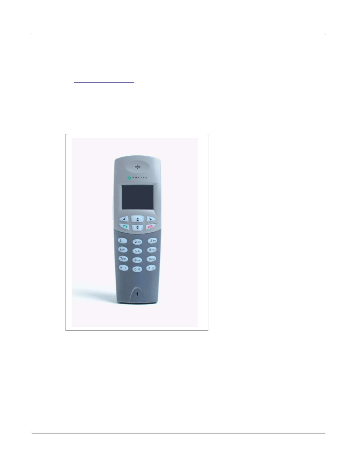
1.2 Phone Description
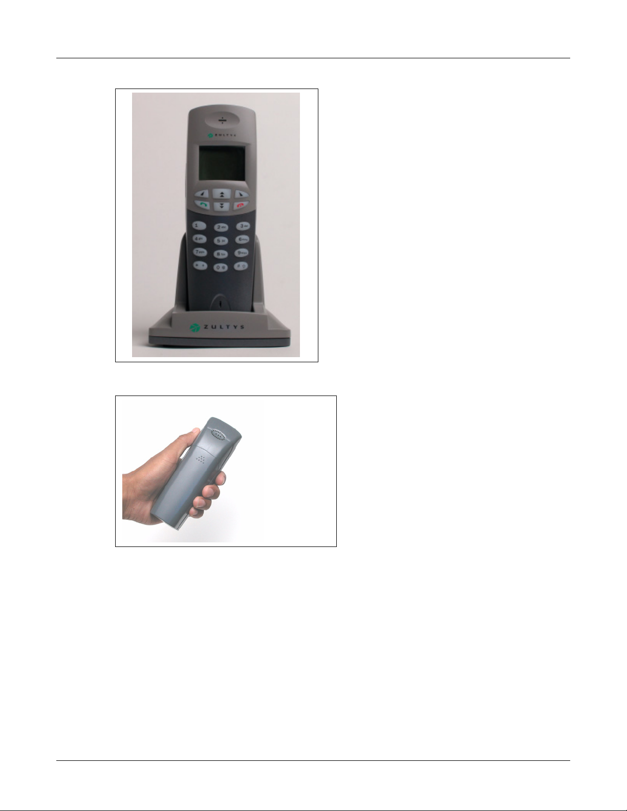
The WIP2 is a SIP based IP phone that provides two call appearances and interacts with network
servers through a wireless access point. Figure 1-1 displays the front side of the phone. The
handset speaker, keypad, and microphone are located on this side of the phone.
Figure 1-1 Top View of WIP 2
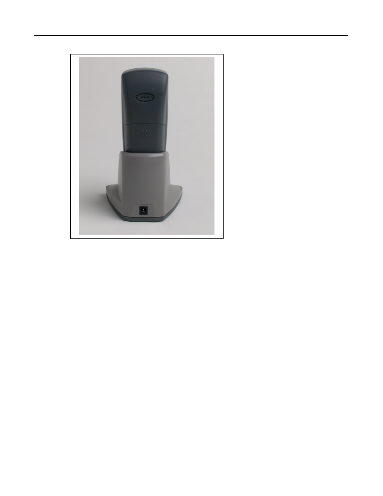
Figure 1-2 displays the rear side of the phone while placed in the charging cradle. The external
speaker is located at the top of the rear side. The rear panel can be removed to place the battery
in the phone. The connector in the middle of the cradle receives power from an ac adapter
1.2.1 Feature Set
Key features of the WIP2 phone include:
• two virtual lines support two simultaneous calls
2
Page 13
1. Introduction
Figure 1-2 Rear view of WIP2 phone and cradle
• handset and speaker modes
• acoustic echo cancellation in speaker mode provides high quality speaker phone
• supports all commonly used PBX functions when used in conjunction with an appropriate call
control system
• receives power from removable battery or ac adapter
• speech encryption ensures that your calls can be kept secure
• easy to create conferences with three people, including those who call you
• 18 buttons provide significant ease of use
• 5 line easy to read display that supports proportionally spaced font
• uses standard SIP messages to interface to a variety of call managers from various
manufacturers
• dial by number or SIP address
• hot key dialling
• critical operational parameters are protected by password
• 100 memory phone book plus 64 location memory for last numbers received or dialled
• based on highly stable Linux operating system
3
Page 14
WIP2 User’s Manual
1.2.2 Display Description
The display is a graphical LCD, 96 dots by 65 dots. It is used mostly to display five rows of
characters. The display utilizes a proportional font, therefore the number of characters on each
row varies. Typically, each row displays about 16 characters. Section 5.2 on page 35 describes LCD
modes and methods of adjusting the display appearance.
1.2.3 Speakers
The WIP2 phone provides a handset speaker and an external speaker. The handset speaker,
located at the top end of the phone’s front side, is used by placing it next to your ear as you speak
into the microphone at the bottom of the phone. The external speaker, located on the rear side of
the phone, allows multiple people to participate in phone conversations.
1.2.4 USB Port
The USB port, located at the bottom of the phone, connects the WIP2 to either a computer for
downloading software updates, or a headset that accommodates hands free mobile use.
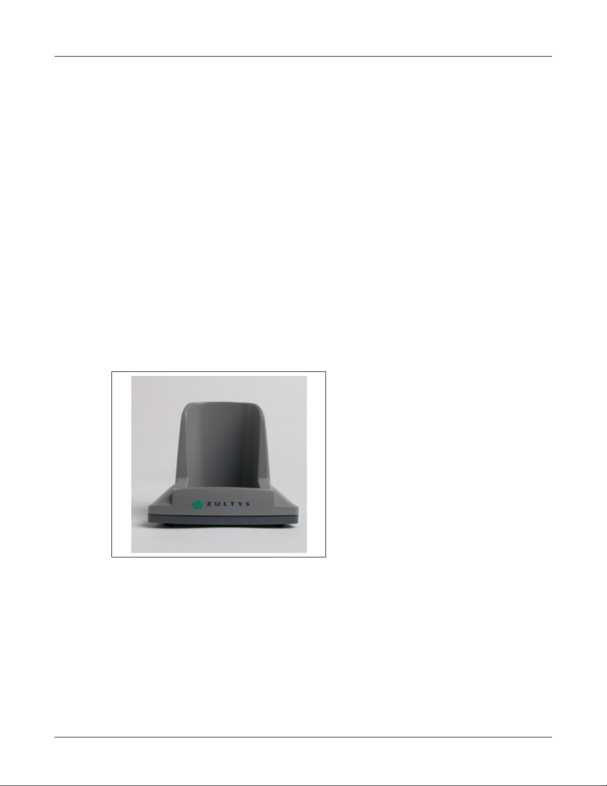
1.2.5 Cradle
The charging cradle, shown in figure 1-3, connects to an power source through an ac adapter and
provides dc power for operating the phone and recharging the battery.
Figure 1-3 WIP2 Cradle
1.3 Documentation Overview
1.3.1 Organization
This user’s manual describes:
• how to install the WIP2 phone
• how to provision the phone for use within the network
4
Page 15

• how to make and receive calls
• how to access the features of the phone
• how to customize the phone to suit your preferences
• what to do when you are convinced there is a problem
1.3.2 Nomenclature
1.3.2.1 Acronyms
This manual often uses acronyms specific to the industry of telecommunications and data
communications. Because the sections (and, to a certain extent, the subsections) can be read in any
sequence, acronyms are not defined in the text. For a complete list of acronyms used in this
manual, see Appendix B, starting on page 177.
1.3.2.2 Jargon
This manual often uses technical terms specific to the industry of telecommunications and data
communications. Very specialized terms are sparsely used, and their meanings are clearly
explained where they are used.
1. Introduction
1.3.3 Special Paragraph Styles
The following are the notices that are used to attract special attention to certain items. They set
text off from the main body of the manual. These notices also appear in other languages where
required by certain regulatory bodies:
Important This notice contains special information that should not be ignored.
Caution This notice calls attention to a condition or procedure which, if not observed, could
result in damage to the phone or the loss of data.
Warning This notice indicates that if a specific procedure or practice is not correctly
followed, permanent damage to the phone and personal injury may result.
Danger This notice warns you of imminent hazard to yourself and others if proper
procedures are not followed.
1.4 Forms of Documentation
This manual is updated with each major release of the software. The manual describes the
features in that release of the software.
5
Page 16

WIP2 User’s Manual
Between major releases of software, Zultys may issue one or more minor releases of software.
These minor releases may have more capabilities than the current formal release. The features in
that software may or may not be described in this manual.
This manual is available only in PDF format. You can download the PDF file from the Zultys web
site at:
http://www.zultys.com
You can obtain old versions of the manual that may describe the software that you have or the
latest manual that describes all the latest features of the product. You can identify the version of
the manual from the title page, opposite the table of contents (page 2 of the PDF file).
When you use the PDF file, you can click on any reference in the text. This powerful feature
allows you to follow the references in the text very easily. Using Acrobat, you can then return to
the page you were previously reading. This is a huge benefit to you if you want to study a small
area of the product.
1.5 Colophon
This document was produced on personal computers using Adobe’s FrameMaker for Windows.
The headings are set in Swiss 721, Bitstream’s version of the Helvetica™ typeface; the copy is set
in Zapf Calligraphic, Bitstream’s version of the Palatino™ typeface; notices are set in Swiss 721 or
News Gothic, Bitstream’s version of the Kingsley-ATF Type Corporation typeface. The drawings
were produced using Adobe Photoshop, Adobe Illustrator, and Microsoft Visio.
1.6 Documentation Feedback
Zultys appreciates any constructive feedback on all our documentation. If you have comments or
error reports on any Zultys documentation, please submit your feedback to:
Technical Publications Department
Zultys Technologies
771 Vaqueros Avenue
Sunnyvale, California 94085 USA
techpubs@Zultys.com
6
Page 17

Receiving the Phone
2.1 Initial Inspection
When the your WIP2 phone shipment arrives, inspect the shipping boxes for external damages
and record any discrepancies. Save the boxes and packing material in case you need to ship the
phone to another facility. Always retain the packing materials if you suspect that the shipment is
damaged — the carrier may need to inspect them.
Warning Do not attempt to use the WIP2 phone or its accessories if it or they appear
damaged. Immediately report the damage your Zultys reseller.
Chapter 2
2.2 Package Contents
2.2.1 Unpacking the Phone
If the phone box has not been damaged in transit, unpack it carefully. Ensure that you do not
discard any accessories that may be packaged in the same box as the phone.
2.2.2 Verify Contents
Upon delivery of your phone, inspect the packing list and confirm that all items listed on that note
were received. Compare the packing slip with your purchase order.
Ensure that the following accessories are present in the shipment:
• phone body
• ac adapter for your country
• charging cradle
• User’s Guide
Ensure that there are no discrepancies and then install the phone as described in Chapter 3,
starting on page 11.
7
Page 18
WIP2 User’s Manual
Important If you suspect that there are discrepancies or that the equipment is not fully
functional, contact Zultys or your Zultys sales representative immediately.
Retain all packing materials and the shipping note for Zultys or its representative
to inspect. ZULTYS CANNOT BE HELD RESPONSIBLE IF YOU CLAIM THAT
AN ITEM IS MISSING, AND YOU HAVE NOT INFORMED ZULTYS WITHIN
THREE DAYS OF RECEIPT, OR IF YOU HAVE NOT RETAINED ALL PACKING
MATERIALS FOR INSPECTION.
2.2.3 Serial Numbers
The serial number of the phone is a twelve character alphanumeric code printed on a white
barcode label located on the bed that holds the battery. To view, remove the back cover of the
phone, as described in section 3.1.2 on page 12, then lift the battery off of the bed. Figure 2-1
displays the location of the serial number label.
Verify the serial number of the phone and compare it to the serial number on the packing lists.
Figure 2-1 Serial Number location
2.3 In Case of Damage or Malfunction
Notify your Zultys sales or service representative under any of the following conditions:
• the shipping container or any of the contents appear damaged
• an item is missing
• there is a discrepancy between the packing slip and the equipment received
• the equipment does not function correctly
Your supplier will arrange for repair or replacement, at Zultys’s discretion. In certain cases, Zultys
may require a claim settlement.
8
Page 19

2.4 Returning Items for Repair or Replacement
2.4.1 Warranty Coverage
Zultys provides a warranty only through distribution channels. If you are an end user, consult
the reseller or distributor who has sold you the phone for complete terms of the product that you
have purchased. Zultys requires that its distributors provide a standard warranty that is one year
in duration and that complies with the local laws and expectations of the country in which you
reside.
Before returning merchandise to Zultys for repair or replacement, you must ensure that the items
are under warranty. If you are unsure about the warranty of your merchandise, call your supplier
or a local Zultys sales representative for clarification. Contact your supplier for a return
merchandise authorization (RMA) number before returning any merchandise; this includes
equipment covered under warranty.
For merchandise not under warranty, you will be charged for a repair if the item is returned to
the factory. Call your supplier for pricing on an extended warranty for your merchandise.
2.4.2 Describing the Problem
If you are returning equipment for service, attach a tag or sheet of paper to the equipment giving
the following details:
2. Receiving the Phone
• your company or institution’s name, address, and phone number
• the main person to contact, an alternative contact, and their phone numbers if different from
the main phone number
• the return shipping address and any special shipping instructions
• the model number and serial number of the equipment being returned
• a description of the failure (If failure is intermittent, describe its frequency and special
conditions that initiate the failure.)
• any additional comments
2.4.3 Accessories
Do not return any of the accessories with the equipment unless you suspect that one of them is
faulty. If you return an accessory, place a tag on it that clearly identifies it as yours and briefly
explain the problem.
2.4.4 Packing
Wherever possible, use the original packing materials to ship the equipment. If these are not
available, containers and cushioning material similar to those originally used are available from
Zultys.
If it is inconvenient to obtain supplies from Zultys, use a strong, double-walled shipping carton.
Place about 70 mm (3 in) of cushioning material around all sides of the equipment.
Zultys is not responsible for any damage that occurs during shipment back to your supplier or to
the factory.
9
Page 20

Chapter 3
Installation
3.1 Preparing the Phone for Use
To use your WIP2 phone, you must supply power to the phone and configure the phone to
communicate to your wireless access points.
Important This device complies with part 15 of the FCC rules. Operation is subject to the
following two conditions: (1) this device may not cause harmful interference, and
(2) this device must accept any interference received, including interference that
may cause undesired operation. The manufacturer is not responsible for any
radio or TV interference caused by unauthorized modifications to this
equipment. Such modifications could void the user’s authority to operate the
equipment.
3.1.1 Connecting the Cradle to Power
The charging cradle is a mobile mounting device that conducts power from the ac adapter to the
phone. Placing the phone in an installed cradle recharges the battery and provides a stable base
for conducting conversations through the external speaker.
To install the charging cradle, place it on a level platform. Then connect the ac adapter to the
connector at the rear of the cradle. After the cradle is installed, you can place the phone in the
cradle as shown in figure 3-1.
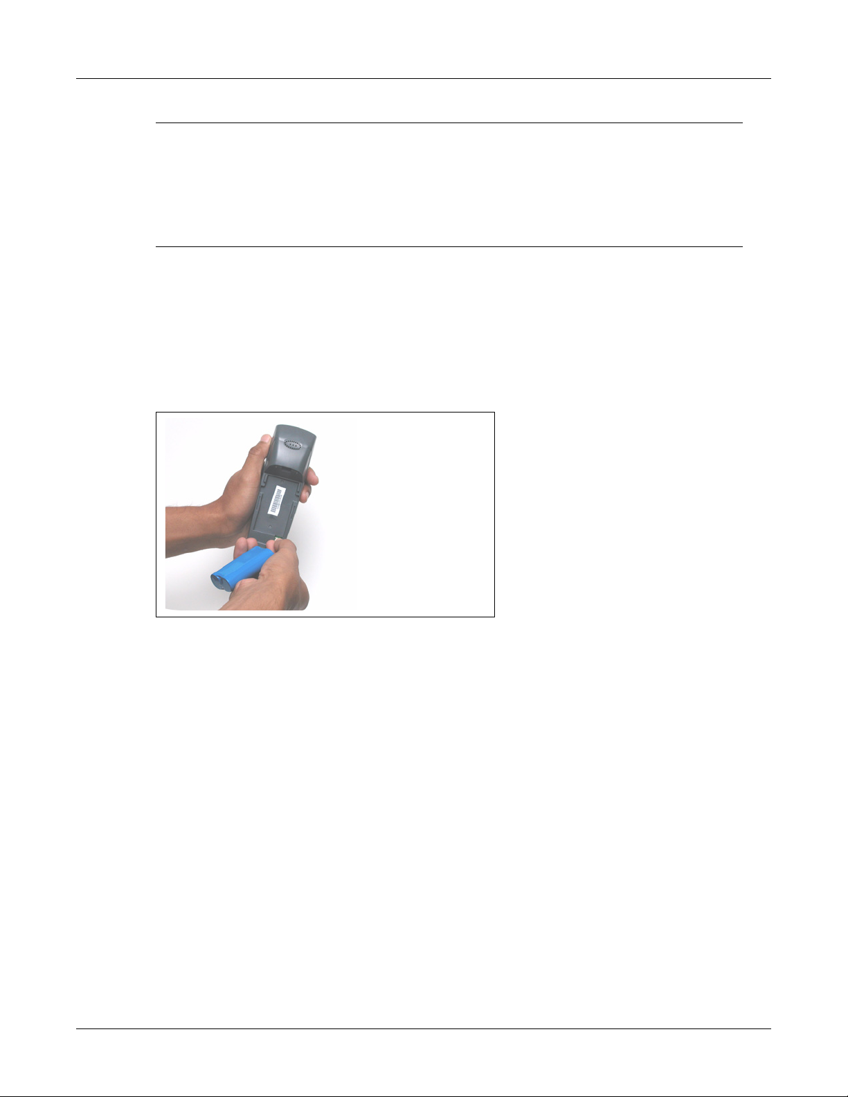
3.1.2 Inserting Battery into Phone
The WIP2 battery is accessed through a removable cover located on the rear of the phone. To
open the rear cover:
1. Firmly grasp the phone with one hand such that the rear side of the phone is up, as shown
in figure 3-2.
2. Press down on the nine raised dots located at the top of the battery cover.
3. While pressing down on the dots, slide the cover towards the bottom of the phone.
4. Lift the cover to access the battery, as shown in figure 3-3.
The battery socket is located on the bottom right corner of the battery compartment.
11
Page 21

Chapter 3
Installation
3.1 Preparing the Phone for Use
To use your WIP2 phone, you must supply power to the phone and configure the phone to
communicate to your wireless access points.
Important This device complies with part 15 of the FCC rules. Operation is subject to the
following two conditions: (1) this device may not cause harmful interference, and
(2) this device must accept any interference received, including interference that
may cause undesired operation. The manufacturer is not responsible for any
radio or TV interference caused by unauthorized modifications to this
equipment. Such modifications could void the user’s authority to operate the
equipment.
3.1.1 Connecting the Cradle to Power
The charging cradle is a mobile mounting device that conducts power from the ac adapter to the
phone. Placing the phone in an installed cradle recharges the battery and provides a stable base
for conducting conversations through the external speaker.
To install the charging cradle, place it on a level platform. Then connect the ac adapter to the
connector at the rear of the cradle. After the cradle is installed, you can place the phone in the
cradle as shown in figure 3-1.
3.1.2 Inserting Battery into Phone
The WIP2 battery is accessed through a removable cover located on the rear of the phone. To
open the rear cover:
1. Firmly grasp the phone with one hand such that the rear side of the phone is up, as shown
in figure 3-2.
2. Press down on the nine raised dots located at the top of the battery cover.
3. While pressing down on the dots, slide the cover towards the bottom of the phone.
4. Lift the cover to access the battery, as shown in figure 3-3.
The battery socket is located on the bottom right corner of the battery compartment.
11
Page 22
WIP2 User’s Manual
Figure 3-1 WIP2 Phone in Charging Cradle
Figure 3-2 Grasping the WIP 2 to remove the rear cover
• To insert a battery into the phone, plug the battery connector into the battery socket, then
place the battery onto the bed.
• To remove the battery, pull the plug up from the socket. Avoid pulling on the wires when
removing the plug from the phone.
12
Page 23
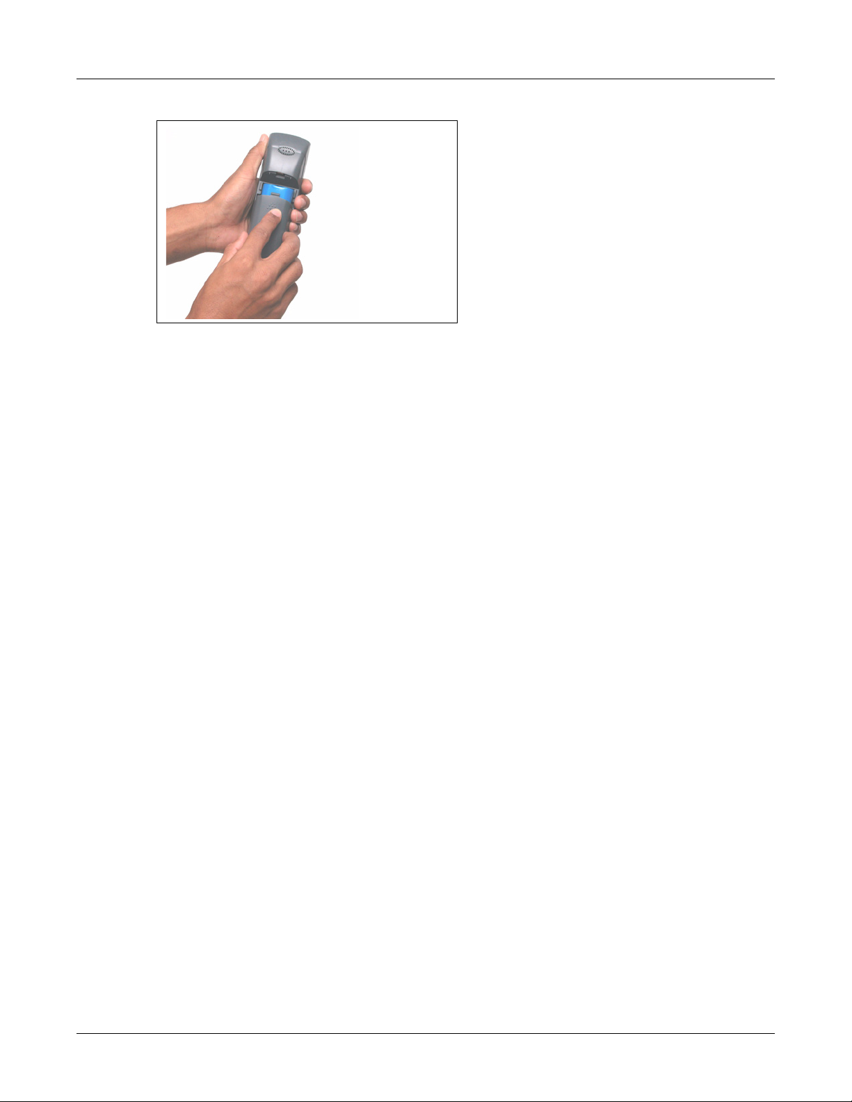
Figure 3-3 Removing the Rear Cover from the WIP 2
3.1.3 Power
3.1.3.1 Power from Battery
The WIP2 can operate independent of the charging cradle when the battery is sufficiently
charged. The battery icon, located in the top right corner of the display, indicates the remaining
power reserves. When fully charged, battery icon displays three bars. The battery icon blinks to
warn you that existing battery reserves can provide power to the phone for less than 15 minutes.
When the icon is not blinking, the battery contains sufficient reserves to power the phone, even
when the icon contains no bars.
3. Installation
3.1.3.2 Power from an AC Adapter
The WIP2 operates from power provided by the ac adapter when the phone is placed in the
charging cradle and the ac adapter is properly connected to the cradle and to an ac power source.
When the battery is being charged, the bars in the battery icon flash on and off sequentially.
The ac adapter has an output rating of 7 Vdc, 850 mA and is marked LPS or (for US) NEC Class 2.
The plug should be 2.0 mm or 2.1 mm with the center positive. Zultys does not warrant operation
of the WIP2 with any adapter not supplied by Zultys for use specifically with the WIP2.
3.1.3.3 Applying Power to the WIP2
The WIP2 receives power from the ac adapter when it is placed in a properly installed charging
cradle, regardless of the charging status of the battery. The phone receives power from the battery
only when it is not receiving power from the ac adapter through the cradle.
3.1.4 Connecting to the Network
LANs provide access to wireless devices through bridge type access points. An access point is a
device that connects to a wired network through an Ethernet port, connects to WiFi devices
through 2.4 GHz radio signals at data rates up to 11 Mbps, and provides transparent
communications between the two networks. A bridge type access point permits communications
13
Page 24

WIP2 User’s Manual
between the networks in both directions. Multiple access points within a network use Layer 2
connectivity, allowing the wireless devices to seamlessly communicate with the LAN as it moves
into areas serviced by different access points.
Refer to section 8.7.2.1 on page 110 for information on scanning the area for access points.
3.2 Power On
3.2.1 Turning the Phone on and off
The WIP2 phone must be powered on in order to make and receive calls, access messages, and
set operation parameters. The phone can be turned on by using one of the following two
methods:
• Press the green button until the first six keys are illuminated. This should take about one
second.
• Place the phone in the charger cradle that is receiving dc power through an ac adapter.
To turn off the WIP 2, remove it from the charger cradle, then press the red button until the
display light turns off. This requires about two seconds.
3.2.2 Power on Sequence
When you power up the phone, it performs a quick power on self test, and typically starts
operation in less than 20 seconds. The exact time depends on your network. The phone tries to
find a DHCP server if DHCP is enabled.
server contains configuration files that fully provision your phone and contains addresses for
network elements used by the phone to can register with the SIP server. Chapter 4, starting on
page 21 describes the exact start up sequence.
3.2.3 Startup panels and Startup tone
The WIP2 signals the start of the power on sequence by illuminated the first six keys. Within two
seconds, the LCD displays the Starting panel. The display remains unlighted.
The key lights are turned off two seconds later. After displaying the starting panel for 15 seconds,
the display light and all key LEDs are turned on. The phone then displays the Copyright logo:
After displaying the Copyright panel, the phone displays information panels while searching for
the DHCP server and TFTP server.
1
The DHCP server points to a TFTP server. The TFTP
1. DHCP is enabled by default. To assign a static IP address to the phone, see section 4.5.2.2 on page 32.
14
Page 25

3. Installation
If your system is configured for multiple locations, the WIP2 displays a panel requesting your
current location. Select a location with the arrow buttons, then press the LEFT button to enter that
location and complete the startup process.
The phone then plays the startup tone, and displays the home panel, as described in section
5.2.2.1 on page 37.
To program the startup tone:
• Menu commands: Section 8.6.7.10 on page 101.
• Configuration commands: Section 9.4.5 on page 145.
• Web Interface Configuration Utility: Section 10.6.5 on page 169.
3.2.4 Running a Quick Test
You can run quick hardware tests immediately after powering on the phone. The WIP2 also
provides a comprehensive set of tests that you can perform whenever the phone is operating
normally. Section 8.8 on page 128 describes the available tests.
To perform the quick test, press and hold the Left Soft Button (located directly above the green
button) during the boot process while the phone displays the Zultys logo. The phone performs
the following tests:
1. LCD alternately displays the following two fixed graphical patterns:
Observe the LCD and verify that all segments are turned on and off.
2. Press the green button to begin LED test. The phone turns on the LED that illuminates the
left side of the LCD and the display shows the following panel:
15
Page 26

WIP2 User’s Manual
3. Press the green button or the right soft button to begin the vibrator test.
4. Press the green button to begin the keypad test
5. After you press all 18 buttons in proper order, the phone displays a completion message:
The WIP2 uses six LEDs to illuminate the display and six LEDs to illuminate the keyboard.
Pressing the left soft button turns off the LED that is on and turns on a different LED.
Pressing the left soft button twelve times steps through each LED through the LEDs.
This test requires that you push each button and key in sequence, starting with the button
in the top left corner of the keypad and proceeding right. The LCD shows an @ symbol for
each button that has been pushed:
The last key pushed in this test is the # key.
If you do not press a button during a 10 second period, the phone displays a timeout
message:
In either case, the phone resumes the power up sequence 10 seconds after displaying one of
these messages.
3.2.5 Communicating with the Network
3.2.5.1 Connecting to a DHCP Server
If the phone is configured for dynamic IP addressing, it attempts to locate a DHCP server. The
phone displays:
16
Page 27

Depending on your network, this can take from two to 30 seconds. The phone displays a progress
bar on the second row and the time it has been trying in the lower right corner of the display, in
minutes, and seconds. Every 20 seconds, the phone clears the progress bar then starts adding
characters again.
The phone continues to try to find the DHCP server indefinitely.
3.2.5.2 Connecting to the TFTP Server
Once the phone has its IP address, it tries to locate the TFTP server if it is programmed with the
address of the TFTP server or if it obtained the address from the DHCP server.
Depending on your network, this can take from one to 75 seconds. The phone displays a progress
bar on the second row and the time it has been trying in the lower right corner of the display, in
seconds.
3. Installation
If the phone can find the TFTP server, the configuration file or files it retrieves may indicate that
the phone needs to update its software. See section 4.4.3 on page 31 for details of the screen that
the phone shows in this case.
If the phone can find the TFTP server but cannot find the configuration file (or it can find it, but
there is an error with it), the phone displays:
The phone displays this for three seconds and then proceeds to register.
The phone continues to try to find the TFTP server for 75 seconds. If it cannot locate the TFTP
server within this time, it displays
The phone displays this for three seconds and then proceeds to register.
17
Page 28

WIP2 User’s Manual
3.2.5.3 Connecting to the SIP Registrar
If the phone has an address for the SIP registrar, it displays:
If the phone is unable to register with the primary SIP proxy, it attempts to register with the
backup proxy (if the phone is configured for a backup proxy). If the backup proxy registration is
successful, calls will be serviced by the backup proxy and the phone will continue attempting to
register with the primary proxy in the background.
3.2.5.4 Failure When Using a Fixed IP Address
If you have configured the phone to use a fixed IP address, and to not use DHCP, the phone
should boot up and connect to the TFTP server (if provisioned) and then connect to the SIP
registrar. If there is a problem with this process, the phone displays:
Use the menu to configure the protected settings as described in section 8.7 on page 107, then
restart the phone.
The phone will also display this message if you have configured it for DHCP but the DHCP server
is incorrectly configured. This is an unusual situation, because administrators take great care to
ensure that the DHCP servers are correctly configured.
3.2.5.5 Attempt to Establish Connection
The phone continually tries to re-establish connection with the network, once every four
seconds.
cycle the power on the phone to make the phone usable.
The phone retains the display until you press a key or until you make a call or the phone receives
a call. You need to use the menu to access the status as described in section 8.5.2 on page 90.
1. The WIP2 sends the second request 500 ms after the first request. It sends the third request 1.0 s after that, the fourth
request 2.0 s after that, and thereafter every four seconds.
1
If it does establish connection, you can use the phone to make calls. You do not need to
18
Page 29
3.2.6 Satisfactory Connections
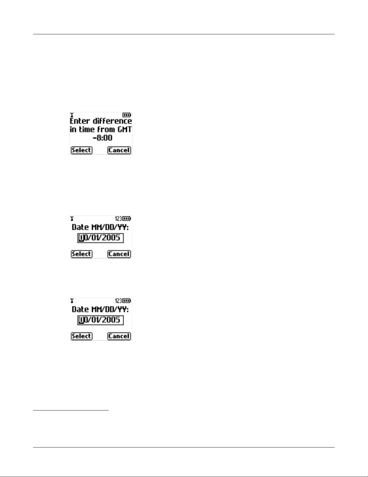
3.2.6.1 Date and Time
The WIP2 receives the time and date from a specified NTP. The time zone can be provided by the
system needs to know the difference between the local time and GMT.
location, the phone therefore displays:
Use the Up and Down keys to select the correct time difference. The phone provides a list of
existing time zones. When you have made your entry, press the LEFT (Select) button. The phone
shows the idle display.
If the phone cannot find an NTP server, you must enter the date and time manually. The phone
displays:
3. Installation
1
Instead of asking for a
Enter the day of the month by using the keyboard on the phone.
Press the OK button. The phone displays:
Use the Up and Down keys to scroll between the months.
Press the OK button. The phone displays:
Use the Up and Down keys to select the correct year. The phone defaults to 2005 scrolls to a
maximum of 2099, then to 2002.
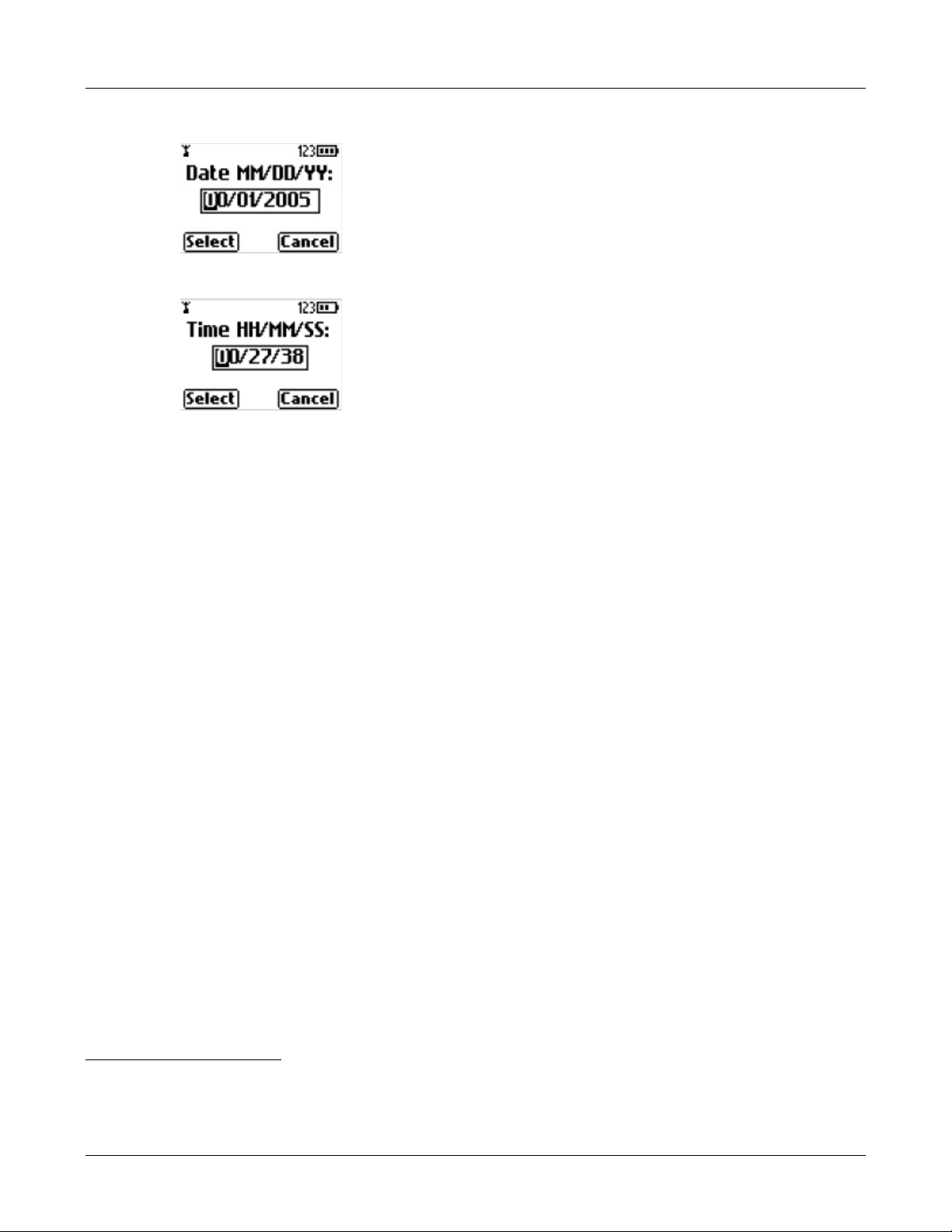
Press the OK button. The phone displays:
1. After the phone has booted it uses SNTP to obtain the date and time for the first time. Thereafter, it uses NTP every ten
to 15 minutes to obtain the date and time.
19
Page 30
WIP2 User’s Manual
Enter the time with the keypad using 24 hour notation.1 Use the * key to enter the colon character
that separates hours from minutes and minutes from seconds. You do not have to enter the
seconds. If you do not enter the seconds, the phone sets the seconds to zero.
Press the OK button when you have entered the time. The phone shows the idle display, as
described in section 5.2.2.1 on page 37.
You can subsequently alter the date and time using the menu as described in section 5.2.3.4 on
page 40, or you can cycle power on the phone to obtain the same screen.
3.2.6.2 Subsequent Loss of Connection
If the phone has established LAN connectivity and registered with the phone system, and then it
loses connectivity, or a subsequent registration request is denied, you cannot make calls. Contact
your system administrator for assistance.
3.2.6.3 Viewing Startup Information
WIP2 provides menu commands and web interface panels that display when the phone was
powered up, when the phone most recently registered with a SIP server, and the network status.
The WIP2 provides the following methods for view startup information and network status:
• Menu commands: Section 8.5 on page 89.
• Web Interface Configuration Utility: Section 10.4 on page 155.
1. Use 24 hour notation regardless of the format you may have chosen in which time is displayed in section 8.6.9.4 on page
106.
20
Page 31

Chapter 4
Provisioning the Phone
4.1 Introduction
Provisioning functions include the booting process that initializes the phone, the configuration
process that customizes your phone, and the update process that allows you to run the most
recent software version of the phone.
You can either dynamically assign an IP address to the phone through a DHCP server or assign
a static IP address. The DHCP server can also be used to obtain the IP addresses of various
network servers. The phone also supports the use of configuration files that can deliver a
common set of phone parameters to various phones throughout a network.
This chapter describes the components used to configure WIP2 phones, the booting and
configuration process, and the method for updating the software that operates the phones. These
sections also present the underlying method for the exchanges that take place.
4.2 Provisioning Methods
4.2.1 Configuration Files
Device configuration files are ASCII text files that specify phone parameter settings. A system user
can setup his or her phone to download its configuration files from the TFTP server every time
the phone is booted.
Each WIP2 phone has a unique MAC address that identifies the device. A TFTP server uses this
address to pass configuration data to the device. Phones can access two configuration files: a
common configuration file and a specific configuration file.
Many parameters in the configuration files correspond to the parameters that you can configure
through the menu of the phone or through the web interface. Configuration parameters are
described in Chapter 9, starting on page 131.
4.2.1.1 Common Configuration File
The common configuration file for the WIP2 is named:
21
Page 32

WIP2 User’s Manual
WIP2_common.cfg
The common configuration file specifies parameter settings that are common for all phones that
access the TFTP server, such as server addresses, registration periods, and service phone
numbers. The common configuration file is stored in the root directory of the TFTP server.
4.2.1.2 Specific Configuration File
The specific configuration file defines parameter settings that are unique to an individual phone
or a set of phones. The specific configuration file is stored in the TFTP directory designated by the
common configuration file.
If a parameter is defined in the common file and the specific file, the specific file setting takes
precedence. The file name of a specific configuration file is constructed by using the MAC ID for
the individual device:
<MAC address>.cfg
For example,
0050C2180FD8.cfg
Each phone, knowing its own MAC address, locates the file that has been uniquely created for it
and obtains configuration data that is unique for the phone.
4.2.1.3 Configuration File Format
The format for common and specific configuration files is identical; an example of a configuration
file is shown in figure 4-1. This is an ASCII text file, with the name of the parameter and the value
of the parameter listed on the same line. Each parameter must be within the section (denoted by
square brackets “[ ]”). The contents of the file are not case sensitive; you can enter parameter
names in upper or lower case. Comment lines are denoted with a leading semi-colon (;) and have
no effect on the operation of the phone.
[HW_CONFIG]
lcd_contrast=8
ring_volume=5
speaker_volume=5
handset_volume=5
[NET_CONFIG]
use_dhcp=yes
ip_addr=
subnet_mask=
default_gateway=
primary_dns=
secondary_dns=
;host_name is DNS lookup for this phone
host_name=
domain=zultys.com
ntp_server_addr=
tftp_server_addr=
tftp_cfg_dir=./WIP2
22
Figure 4-1 Format for Configuration File
Page 33

[SIP_CONFIG]
phone_sip_port=5060
rtp_start_port=33000
;The Device ID is the user portion of the SIP URI
device_id=West
;The Display Name is sent in SIP messages
display_name=Zultys WIP2
register_w_proxy=yes
proxy_addr=10.1.32.224
proxy_port=5060
voice_mail_uri=258
registration_expires=3600
session_expires=3600
[AUDIO_INFO]
ext_ring_tone=0
ext_cust_ring=
int_ring_tone=0
int_cust_ring=
ring_tone2=0
cust_ring2=
key_click=0
codec=0
distinctive_ring=yes
sound_url=
4. Provisioning the Phone
[GENERAL_INFO]
software_version=1.0.0
;The message displayed on the LCD in idle mode
greeting_message=WIP2 SIP Phone
password=985897
time_fmt=%H:%M
date_fmt=%m/%-d/%Y
date_time_order=0
;This is the offset from GMT, in minutes
timezone=-480
country=USA
language=ENGLISH
clear_settings=2
Figure 4-1 Format for Configuration File (Continued)
4.2.1.4 Accessing the Configuration Files
Every time the phone restarts (either by command or by power on), the phone may read the
configuration files. The phone extracts the data in the files and saves it to memory. This
overwrites all parameters that are saved in memory except for user settings that are not
configured to be cleared; these settings are retained in the phone.
For example, suppose the common configuration specifies the greeting message as:
WIP2 SIP Phone
and the specific configuration specifies the greeting message as:
23
Page 34

WIP2 User’s Manual
Freddy Phone
Then, in the idle state, the phone will display:
The phone continues to start, using the parameters that are now saved in its memory.
4.2.1.5 Retaining User Settings
Configuration commands either specifies parameter values that the phone requires to
communicate with the network servers or setup the behavior of features that define how you
interact with the phone. Personal interaction features include:
• display properties, including the LCD contrast, greeting message, date format, time format,
and the display timeout, and the display language.
• volume settings, including the ring, handset, and speaker volume
• phone alert tones, including ring tones, second call tone, hold reminder tone, key click sound,
and stutter tone
• automatic call answer settings
Specific information about each of these settings is listed in the following chapters. Each of these
settings can be altered through configuration commands, permitting the reset of feature values
each time you power up the phone. Additionally, the WIP2 can be configured to specify when
these user settings are reset, allowing you to retain preferred settings that differ from
configuration file commands even when the phone is rebooted.
The Clear User Settings command provides three options.
• Never: Each time the phone powers on, it retains the user settings that were previously
entered
• On Next Power On: The phone modifies user settings to the values listed in the configuration
file the next time it is powered on. After that instance, the phone sets this parameter to never
and will not take settings from the configuration file again unless you manually alter this
setting.
• On Each Power On: The phone takes its user settings from the configuration file every time
the phone powers up.
The WIP2 provides the following methods for scheduling the clearance of user settings:
• Section 8.6.5 on page 95 describes the menu commands that clear the user settings.
24
• Section 9.4.3 on page 140 describes the configuration commands that clear the user settings.
• Section 10.5.1 on page 158 describes the Web Interface panel that clear the user settings.
Page 35

4.2.2 Web Interface Configuration Utility
The phone provides a web interface configuration utility, offering an alternative method of
storing information to your phone. Through this utility, you can modify all operating parameters
that are available through configuration files.
To access the web interface, enter the IP address of your phone in the address entry box of your
web browser and press the key button. The login panel will appear in your browser. Section
8.7.3.2 on page 114 provides the menu command that displays your phone’s IP address.
Web Interface panels provide an update button to download changes to your phone. Many
changes take effect when you download them to the phone. Some changes require that you
reboot the phone to become enabled. When you have made at least one change that requires a
phone reboot, a Restart Phone option appears in the menu on the left side of the panel.
If you have specified a TFTP server, restarting the phone reloads the configuration files to the
phone which files may write over the changes specified by the web interface; see section 4.3.1.2
for details on booting the phone without reloading the configuration files.
Chapter 10, starting on page 151, describes each panel of the web interface configuration utility.
4.3 Boot Process
4. Provisioning the Phone
4.3.1 Boot Options
The phone provides several boot process options, allowing you to customize the phone to your
network configuration. This section describes the process options, then lists the steps that the
boot up process requires.
4.3.1.1 IP Address Assignment Options
Dynamic IP and TFTP Address Assignment. This option uses DHCP to specify the IP address and
subnet mask of the phone, the IP address of the default gateway, and the IP address of the various
network servers that the phone will access. Figure 4-2 displays the configuration commands that
specify this option.
[NET_CONFIG]
use_dhcp=yes
tftp_addr_fixed=no
Figure 4-2 Configuration File Instructions: Dynamic IP and TFTP Assignment
Dynamic IP Address and Fixed TFTP Address Assignments. This option uses DHCP to specify the
IP address and subnet mask of the phone, the IP address of the default gateway, and the IP
address of the various network servers that the phone will access except for the TFTP server. The
IP address of the TFTP server is either provided by the configuration file or retained from the
previous setting in the phone’s internal memory. Figure 4-3 displays the configuration commands
that specify this option.
Fixed IP Address Assignment. This option fixes the phone’s IP address and subnet mask and the
IP address of the default gateway and all of the various network servers that the phone will
access. Figure 4-4 displays the configuration commands that specify this option.
25
Page 36

WIP2 User’s Manual
[NET_CONFIG]
use_dhcp=yes
tftp_addr_fixed=yes
tftp_server_addr=10.1.32.224
Figure 4-3 Configuration File Instructions: Dynamic IP, Static TFTP Assignment
[NET_CONFIG]
use_dhcp=no
tftp_addr_fixed=yes
tftp_server_addr=10.1.32.224
Figure 4-4 Configuration File Instructions: Static IP and TFTP Assignment
4.3.1.2 Configuration File Usage Options
Download Configuration Files. This option downloads the common and specific configuration
files from the TFTP server and stores the values specified by the commands in the files into the
memory of the phone. To download configuration files, you must either enable DHCP mode and
specify dynamic TFTP address assignment, or specify fixed TFTP assignment and assign a valid
IP address to the TFTP address parameter.
Do Not Access Configuration Files. This option does not download any configuration files from
the TFTP. The phone uses its memory contents to configure itself upon startup. To perform this
option, specify fixed TFTP assignment (see section 8.7.3.8 on page 117) and assign an empty value
to the TFTP address parameter (see section 8.7.3.9 on page 117).
4.3.2 Boot Process Description
The following steps provision the WIP2 phone:
1. The phone obtains its IP address and the address of the TFTP server. These addresses are
obtained in one of the following ways:
• dynamic assignment by accessing the DHCP server
• static assignment from the configuration file
• maintains address assignment as configured in the phone’s internal memory
2. The phone accesses the TFTP server to locate the common configuration file. If the TFTP
address parameter does not specify an address to the TFTP server, the phone does not access
the common configuration file.
3. If the phone downloaded the common configuration file, it reads the file and accesses the
specific configuration file from the directory pointed at by the common configuration file.
4. The phone reads its specific configuration file.
5. The phone stores the data retrieved from the configuration files in its internal memory.
26
6. The phone uses the parameter settings in its internal memory to configure itself to operate
properly in the network.
Page 37

4.4 Updating Software
Zultys periodical releases new versions of the software that controls the WIP2. New versions may
provide additional features or enhance the performance of the phone. The following sections
describe the phone software update process.
To view the software version that the phone is running, along with the date of manufacture, MAC
address, boot code version, and hardware version:
• Menu commands: Section 8.5.3 on page 91.
• Web Interface Configuration Utility: Section 10.4.3 on page 157.
4.4.1 Performing an Update
The phone must be able to communicate with the LAN that has a TFT P server and a DHCP server.
DHCP mode must be enabled to perform the software update.
Important You cannot update the software if you fix the IP address of the phone.
The DHCP server provides an IP address to the phone and also the address of the TFTP server.
The phone accesses the TFTP server to locate and retrieve its configuration files. It reads the
configuration files to identify what software version it should be using. If the files specify a
different version from that on the phone, the phone retrieves the specified software version from
the TFTP server.
4. Provisioning the Phone
The WIP2 provides two modes for updating software. Forced updates are performed
automatically by the system administrator. Manual updates are performed by the user.
4.4.1.1 Forced Software Updates
Forced software updates are initiated by the system administrator and received by the WIP2 from
configuration files received from the TFTP server.
Important To receive a manual update, the phone must be placed in the charger cradle and
receiving power from the ac adapter.
After completing the software update, the Forced Software Update process automatically powers
down the phone, then turns the power on.
4.4.1.2 Manual Software Updates
The following procedure initiates a manual software update:
1. Verify that the phone is powered off.
2. Press and hold the “1” key. While holding the “1” key, turn on the phone by pressing the
green SEND button until the top six number keys are illuminated.
The phone displays the Update agent screen:
27
Page 38

WIP2 User’s Manual
3. If necessary, change the parameter values to contact the server that will provide the software
4. Press the Right button (Apply) to begin the update.
5. Power up the phone to complete the software update.
update.
Press the green SEND button to move between fields. Press the Up button to backspace. You
can also scan for available Access Points by pressing the Left button (Scan).
During the update, the WIP2 displays a sequence of screens that display update status and
information, such as the TFTP server address and the software version number.
When the server has completed sending the update, the phone will automatically power off.
4.4.2 Update Process
4.4.2.1 Description
To update the software, one or both of the configuration files described in section 4.2.1 on page 21
must specify the software version that the phone must use. This is specified on the line shown in
figure 4-1 as:
The phone compares the version specified to that installed on the phone. If the versions are the
same, the phone continues with the startup process. If the versions are different, the phone
retrieves the software from the TFTP site. The phone looks first in the root directory of the TFTP
site, then in the subdirectory of the TFTP site where the specific configuration file may be stored,
if one is specified.
The software name for WIP2 software is:
For example:
The file name uses the underscore character to separate the three parts of the software version
number.
If the common configuration file and specific configuration file indicates a different software
versions, the phone retrieves the software version specified by the specific configuration file.
software_version=1.0.3
WIP2_<version>.bin
WIP2_1_0_3.bin
28
The phone programs itself with the new software and restarts.
Page 39

4.4.2.2 Binary File
The binary file for the software contains the software version. When the phone reads the file, it
verifies the version that is contained in the file with the file name and will not load it if the
versions do not match.
The first characters in the binary file are encoded as a null terminated ASCII string. The end of the
file contains a 16 bit CRC checksum.
The size of the binary file is between 2 MB and 4 MB.
4.4.2.3 Ladder Diagram
Figure 4-5 shows the messages used in this process for the WIP2. The following steps describe the
process of obtaining the TFTP address from the DHCP server. If the TFTP server address is fixed
by the configuration file or web interface, the phone accesses the specified TFTP server and
continues with Step 5.
1. WIP2 sends DHCP DISCOVER (broadcast)
The WIP2 boots (after power is initially applied or after receiving a SIP NOTIFY message)
and sends out a DHCP DISCOVER message requesting an IP Address and other options
(same as those provided in DHCP ACK).
4. Provisioning the Phone
2. DHCP Server responds with a DHCP OFFER
The DHCP Server indicates an available IP Address to the WIP2.
3. WIP2 sends DHCP REQUEST (broadcast)
The WIP2 accepts the DHCP server’s offer and asks the server to provide its configuration.
4. DHCP Server sends DHCP ACK
DHCP Server responds with committed IP Address and other configuration options. The
specific options needed by the WIP2 are described in section 4.5.2.1 on page 32.
5. WIP2 initiates TFTP read request for WIP2_common.cfg
WIP2 requests its common configuration file using the TFTP Server address provided by
DHCP option #66.
6. WIP2 receives TFTP data (WIP2_common.cfg) from the TFTP Server
The WIP2 receives the common configuration file and reads it. It is possible that the specific
configuration file for a phone is located in a directory that is not the TFTP root directory. If
this is the case, the subdirectory is indicated in this common configuration file.
7. WIP2 initiates TFTP read request for MAC_address.cfg
The WIP2 requests its specific configuration file. The specific configuration file is uniquely
named with the specific MAC address of the phone (for example, 0008A10FF312.cfg).
8. WIP2 receives TFTP data (MAC_address.cfg) from the TFTP Server
The WIP2 reads its specific configuration file and determines whether its software version
matches that specified. If not, it retrieves the new software.
9. WIP2 initiates TFTP read request for WIP2_version bin.
The WIP2 requests the specific software version using the TFTP Server address provided by
DHCP option #66 (for example, WIP2_1_2_34.bin).
29
Page 40

WIP2 User’s Manual
30
Figure 4-5 Messages for WIP 2 to Obtain Configuration
10. The WIP2 receives TFTP data (WIP2_version.bin) from the TFTP Server
After downloading the software version the WIP2 reboots and repeats all of the steps (except
for retrieving software). At this point, the WIP2 performs a checksum verification and
compares the new software version file name with the version information stored internally
to the .bin file. If the checksum fails or if the file name does not match that of the version
information stored internally to the .bin file, the phone indicates an error and loads the
previous software version.
Page 41

4.4.3 Summary
For a user, the process of updating the software is fully automatic. The administrator of the
network can initiate this process at any time. When the phone is idle, it will start the process of
updating the software. Usually, the administrator would cause this to happen when no one is
likely to want to use the phone. The phone displays an update message using different characters
than normal.
Important Do not disturb the phone during the update process. You cannot use the phone
When the phone has provisioned the software, it restarts itself, just as it does when you power it
on. After about 15 seconds the phone displays the idle display and is ready to use.
If the software update process fails, the phone may display a message indicating that the
Application update failed. The phone displays this message if it found the software file but the
file had been corrupted. Contact the system administrator to resolve this. You will not be able to
use the phone until you resolve the problem.
4. Provisioning the Phone
to make or receive calls while the software is being updated. This process takes
about 30 seconds.
4.5 Provision Settings
4.5.1 Wi-Fi Parameters
Wi-Fi parameters configure the connection between your wireless networks and the WIP2
phone. Section 8.7.2 on page 110 describes the menu commands that adjust Wi-Fi parameter
settings. Section 8.5.2.1 on page 90 describes the menu commands that display wireless network
parameters settings.
The WIP2 defines the following Wi-Fi parameters:
• SSID: The Service Set Identifier (SSID) specifies the wireless network that the WIP2 is
accessing. The SSID setting enables communications between the WIP2 and the access points
of the specified network.
• Network: The Network setting specifies the communication method the phone uses to
communicate with other devices. The valid network options include:
— Infra (Infrastructure): In this mode, wireless devices communicate with other devices,
either other wireless devices or wired devices, after going through an access point.
— Independent: Also known as Ad-hoc mode. In this mode, devices communicate directly
with each other without the use of access points.
• Channel: A channel is a division of the 2.4 GHz wireless band that supports a transmission
path. The WIP2 supports 11 channels in the US, 13 channels in Europe, and 14 channels in
Japan. The channel is not configured by the user.
• WEP: Wired Equivalent Policy (WEP) is a security protocol for wireless networks. WEP
encrypts data over radio waves as it is transmitted between endpoints. When this parameter
is enabled, the phone encrypts all voice transmissions.
31
Page 42

WIP2 User’s Manual
• WEP Keys: A key is an integer variable that an algorithm applies to a data block to produce
encrypted data. This option specifies the WEP keys available for data transmissions when
WEP is enabled.
• WEP Active Key: This parameter selects the WEP key used by the WIP2.
4.5.2 IP Settings
IP settings configure the IP address of the WIP2 and the servers required by the phone. When
operating in DHCP mode, the DHCP server provides all of the IP addresses. When DHCP is
disabled, the phone is configured in static IP address mode and uses the addresses stored its
memory.
4.5.2.1 DHCP Mode
You can dynamically assign the IP address of the phone and other network servers by accessing
a DHCP server. When you connect the phone to a DHCP server, the DHCP server must be
configured with the following options for your network to fully support the phone:
• subnet mask (option 1)
• default gateway (option 3)
• domain name server (option 6)
• IP Address (option 50)
• TFTP server name (option 66)
In addition, it is recommended that your DHCP server also provide:
• NTP Time Offset (option 2)
• domain name (option 15)
• NTP servers (option 42)
The WIP2 provides the following methods for enabling DHCP mode:
• Menu commands: Section 8.7.3.1 on page 114.
• Configuration commands: Section 9.4.1 on page 133.
• Web Interface Configuration Utility: Section 10.6.2 on page 165.
4.5.2.2 Fixed Address Mode
When the WIP2 boots with DCHP mode disabled, the IP address and subnet mask of the phone
must be configured in memory. IP addresses of the following devices and servers must also be
stored in the phone’s memory:
• Default Gateway: The Default Gateway is the IP address of the router that the phone uses to
communicate with the outside world.
32
• DNS Servers: DNS servers is a device that locates records to answer IP address queries. The
WIP2 allows the configuration of primary and secondary DNS servers.
• NTP Server: An NTP server is a device that maintains a common clock time among hosts
within a network.
Page 43

• TFTP Server Address: TFTP servers are typically accessed by devices to receive their "boot
strap" information. When DHCP is disabled, the TFTP IP address is configured as a fixed IP
address.
• DSCP Setting: This parameter configures DiffServ (layer 3 QoS) setting. All voice packets
(RTP) leaving the phone will have the ToS byte in the IP header set to this value. The default
value is 0, which corresponds to best effort. If you use differentiated services in your network,
you should set the value to 46 (101110 binary) which corresponds to the expedited forwarding
per hop behavior (PHB)
The WIP2 provides the following methods for setting network IP addresses:
• Menu commands: Section 8.7.3 on page 113.
• Configuration commands: Section 9.4.1 on page 133.
• Web Interface Configuration Utility: Section 10.6.2 on page 165 configures the IP address and
subnet mask of the phone. Section 10.6.1 on page 164 configures all other network IP
addresses.
4.5.3 SIP Settings
4. Provisioning the Phone
4.5.3.1 Registration Address
When registering with a SIP proxy, each device provides an address (SIP URI) in the form
device_id@domain, where device_id identifies the specific device and domain specifies the
domain name for the enterprise. The default device_id is the MAC address of the phone.
The WIP2 provides the following methods for setting network IP addresses:
• Menu commands: Section 8.7.5.1 on page 124 (user name) and section 8.7.5.2 on page 124
(domain).
• Configuration commands: Section 9.4.2 on page 136.
• Web Interface Configuration Utility: Section 10.6.4 on page 168.
4.5.3.2 Proxy Addresses
SIP settings include the parameters required by the phone to communicate with the SIP proxy
and registrar servers. The phone can be configured to either register with a registrar server or the
SIP Proxy; you can also program the phone to register with neither device.
SIP proxy parameter settings include:
• Proxy Address, Port, and Password: These parameters specify the IP address and the TCP or
UDP port of the server that handles call control for the phone. The default proxy port is 5060.
You can also specify a password for servers that requires device authentication.
• Backup proxy address and port: These parameters specify the IP address and the TCP or UDP
port for a backup proxy server. The default proxy port is 5060. You can also program the phone
to register with the backup proxy at startup.
• Registration Expires: This parameter specifies the time period, in seconds, after which a
REGISTRATION expires. This value is inserted into the Expires header field.
33
Page 44

WIP2 User’s Manual
• Subscription Expires: This parameter specifies time period, in seconds, after which a
SUBSCRIBE expires. This value is inserted into the Expires header field.
• Backup Registration Expires: This parameter specifies the time period, in seconds, after which
a REGISTRATION expires for the Backup proxy. This value is inserted into the Expires header
field.
• DNS SRV Lookup: This parameter configures the phone to resolve the SIP Proxy IP address
through DNS SRV records.
• Registrar address and port: These parameters specifies the SIP registrar server address and
port. When this value is set and registration is enabled, the phone attempts to register with
this server instead of the proxy server. The default proxy port is 5060.
• Phone SIP Port: This phone specifies the transport port number that is uses to receive SIP
messages.
• RTP Starting Port: The phone uses consecutively numbered RTP and RTCP port numbers
(actually UDP port numbers) for communication. RTP carries media and RTCP carries control
information. The default RTP start port is 1760.
• Transport Protocol: This parameter specifies the protocol used to transport SIP messages.
Currently, the WIP2 only supports UDP transport.
• Invite Retransmissions: This parameter specifies the number of unsuccessful INVITE
transmissions before the phone switches to the backup proxy.
• Non-Invite Retransmissions: This parameter specifies the number of unsuccessful
retransmissions (other than INVITE) before the phone switches to the backup proxy.
• Validate Request URI in SIP messages: When this parameter is set to Yes , the phone verifies
the IP address, Device ID, and port number of any SIP messages that it receives. If these
parameters do not match those of the phone, the SIP message is discarded.
The WIP2 provides the following methods for setting network IP addresses:
• Menu commands: Section 8.7.4 on page 118.
• Configuration commands: Section 9.4.2 on page 136.
• Web Interface Configuration Utility: Section 10.6.3 on page 166.
4.5.4 Codec Settings
Codecs are algorithms that the phone uses to encode voice data. The WIP2 provides the following
four codecs:
• G.711-µ-law: typically used in North America and Japan
• G.711 A-law: typically used everywhere else
• G.729 A: used in bandwidth restricted networks
• G.729 AB: used in bandwidth restricted networks
The WIP2 provides the following methods for setting network IP addresses:
34
• Menu commands: Section 8.7.6.1 on page 126.
• Configuration commands: Section 9.4.5 on page 145.
• Web Interface Configuration Utility: Section 10.6.5 on page 169.
Page 45

Chapter 5
Interacting with the Phone
5.1 Call Appearances
The WIP2 phone has two call appearances. Each call appearance supports a separate voice call.
This type of phone is different from phones in common use for the past 100 years. On those older
phones a physical pair (or two pairs) of wires carry a single voice call. A phone that can
accommodate two voice calls connects to two such circuits, with each circuit being referred to as
a line. A switch on the phone selects between the lines (and therefore with whom you are talking).
A phone that has two lines has two such sets of circuits and can allow two simultaneous calls.
The WIP2 phone has a single circuit to connect to the switch. All calls take place over this same
circuit, or line. Dedicated software and hardware inside the phone and the switch support two
simultaneous conversations. These are referred to as two call appearances, not two lines.
5.2 Display
The display, located below the handset speaker and above the buttons, is a graphical LCD, 96 dots
65 dots that displays five rows of characters. The display utilizes a proportional font, therefore the
number of characters on a row varies on the basis of the text being displayed. Typically, the
display shows about 16 characters.
The WIP2 provides a back light that illuminates the display when you press a button or during a
call. The back light automatically turns off after the phone has been inactive for 30 seconds.
5.2.1 Display Organization
The LCD comprises the following three component rows: the icon bar, the text display, and the
menu bar.
35
Page 46

WIP2 User’s Manual
5.2.1.1 Icon bar
The Icon bar is located at the top of the LCD and displays one or more icons that indicate WIP2
status. Icons displayed by the WIP2 include:
• The Antenna icon, located in the left corner of the Icon bar, indicates the reception level of the
signal being received from the specified network. This icon displays a small antenna figure
followed by 0-4 bars: zero bars indicates that the phone is not receiving a signal; four bars
indicates the phone is receiving a strong signal.
• The Handset icon indicates that the phone is servicing a voice call in Handset Listening mode.
• The Speaker icon indicates that the phone is servicing a voice call in Speaker mode.
• The Envelope icon indicates that you have an unread voice mail or text message.
• The Key icon indicates the keypad is locked
• The Padl oc k i c on indicates the phone is servicing an encrypted call.
• The Alphanumeric icon indicates the case mode for entering digits and characters. See section
5.3.5.3 on page 43.
• The Battery icon indicates the remaining battery reserves. The number of bars in the battery
indicates the status of the battery:
— three bars indicates a fully charged battery
— zero bars indicates a operational battery with limited reserves
— flashing bars indicates the battery is being charged
— a blinking battery, with no bars, indicates the battery is almost discharged and the phone
will turn off in less than three minutes.
The icon bar in the above figure displays the antenna, handset, and battery icons.
5.2.1.2 Status Bar
The Status Bar comprises three rows in the center of the LCD that displays phone status,
configuration menus, date, time, a greeting message, and calling options. Status Bar contents
depend on the operational status of the phone.
The status bar in the above figure displays 1. Connected on the first line, Bonnie Hopkins on the
second line, and the QoS icon with the time of day on the third line.
5.2.1.3 Option Bar
The Option bar, located at the bottom of the display, shows options triggered by pressing the
LEFT soft button and the RIGHT soft button. The available options depend on the status of the
WIP2. Option bar options displayed by the WIP 2 include:
• Answer: Press the soft button to answer an incoming call.
• Back: Press the soft button to return to the previous view.
36
• DND: Press this soft button to send an incoming call directly to voice mail.
• Exit: Press this soft button to return the Status Panel to the greeting message view.
• Menu: Press this soft button to access the configuration menus.
Page 47

• Mode: Press this soft button to change the case mode when in alphabetic mode.
• Options: Press this soft button to access a list of calling options.
• Presence: Press this soft button to change your user presence.
• Select: Press this soft button to select the highlighted menu option.
• Store: Press this soft button to store the Status Panel contents to the phone book.
The sample panel displays Options for the LEFT soft button and Mode for the Right soft button.
5.2.2 Display Panels
The WIP2 phone displays call status and configuration settings through the LCD. The following
sections describe WIP2 panels displayed by the LCD.
5.2.2.1 Home panel
The WIP2 displays the Home panel when the phone is not servicing a voice call and an option list
is not available.
5. Interacting with the Phone
• the Icon Bar displays the Antenna icon and the Battery icon
• the Status Bar displays the greeting message (WIP2 Phone) on the top row, the time on the
center row, and the date on the bottom row
The contents of the center and bottom rows are configured by the Time and Date order
parameter, as described in section 5.2.3.4 on page 40.
• the Option Bar displays Menu (LEFT button) and Presence (RIGHT button) options.
5.2.2.2 List Panels
List panels display a set of available options. The WIP2 uses List Panels to navigate through
configuration menus or to display available calling options as you use the phone. List panels
comprise the following components:
• The Icon Bar displays the name of the List (Options). This name often includes the menu path.
37
Page 48

WIP2 User’s Manual
• The Status Bar displays the available menu options (Pick up, Pag e , and Text Message). The
black bar is the cursor that indicates the highlighted option (Pa g e). A scroll bar on the right side
of the Status Bar indicates the list contain additional options that are not displayed.
Press the UP and DOWN buttons to move the cursor through all available options.
• The Option Bar displays the actions performed by pressing the LEFT (Select) or RIGHT (Exit)
soft buttons.
Pressing the Select option activates the highlighted option. The WIP 2 behavior that is
triggered by pressing the Select button depends on the type of option selected
— Menu options open another List panel. The WIP 2 implements a hierarchical menu
— Parameter options open a Selection panel for specifying a parameter setting. See section
— Action options display a data entry panel for specifying contact information. This
— Information options display an Information panel that displays a parameter setting. See
structure that provides access to configuration settings through layers of List panels often
referred to as menus and submenus. See section 5.5 on page 47.
5.2.2.3.
information may be added to the WIP2 phone book or used to establish a voice call or send
an instant message. See section 5.2.2.4.
section 5.2.2.5.
5.2.2.3 Action Panels
WIP2 activity that affects the contents of the Status Panel includes dialling a call, sending a call,
receiving a call, servicing an active call, and disconnecting a call. Chapter 6, starting on page 53,
describes the display contents during all phone activities.
5.2.2.4 Selection Panel
The phone displays a Selection panel when you press the LEFT (Menu) while a Menu panel
highlights an option that requires a parameter setting. The sample menu panel is displayed by
selecting Menu | User Settings | Right Button from the Home panel.
When the phone displays a selection panel:
• The Icon Bar displays the name of the parameter (Right button) that panel is configuring.
• The Status Bar displays the parameter setting options (Presence, Pa ge , and Phone book). The
circles on the left side indicates the present parameter setting. A scroll bar on the right side of
the Status Bar indicates the list contain additional options that are not displayed.
38
Page 49

In the above panel, Presence is the current setting and Pa ge will be activated if you select the
LEFT (Select) button. A scroll bar on the right side indicates that additional options can be
displayed by pressing the UP or DOWN buttons. The black bar is the cursor that indicates the
highlighted option (Pa ge ).
• The Option Bar displays the Select and Back options that are activated by pressing the LEFT
or RIGHT buttons. Pressing LEFT (Select) activates the highlighted option and returns to the
previous panel. Pressing RIGHT (Back) returns to the previous menu panel without activating
the highlighted option. Pressing the red END button returns to the Home panel without
activating the highlighted option.
5.2.2.5 Information Panel
The phone displays an Information panel when you select a menu option that returns a
parameter setting. The following panel is displayed by selecting Menu | Information | Times |
Powered on.
5. Interacting with the Phone
The phone begins displaying the Information Panel when you select the specified menu option
and continues displaying the panel for the period specified by the Event Timer (section 5.2.4).
WIP2 parameters cannot be modified from an Information panel. Some Information panels
display parameters that can be adjusted from a Selection panel. Other Information panels display
information that cannot be configured, can be changed only by power cycling the phone, or is
changed automatically as the phone is being used.
5.2.3 Adjusting the LCD
5.2.3.1 Contrast
The contrast setting adjusts the display darkness to improve its readability. The display
readability is affected by ambient light, room temperature, and the angle at which you view the
display. To adjust the LCD contrast:
• Menu commands: Section 8.6.1 on page 92.
• Configuration commands: Section 9.4.4 on page 144.
• Web Interface Configuration Utility: Section 10.5.1 on page 158.
5.2.3.2 Greeting
The Greeting is the message displayed on the top line of the Status panel when the phone is idle
In the following panel, the greeting message is Jack’s Phone.
To change the LCD greeting:
39
Page 50

WIP2 User’s Manual
• Menu commands: Section 8.6.4 on page 94.
• Configuration commands: Section 9.4.3 on page 140.
• Web Interface Configuration Utility: Section 10.5.1 on page 158.
5.2.3.3 Language
The WIP2 can display LCD text in one of several languages. To change the display language:
• Menu commands: Section 8.6.9.2 on page 106.
• Configuration commands: Section 9.4.3 on page 140.
• Web Interface Configuration Utility: Section 10.5.4 on page 163.
5.2.3.4 Date and Time Format
The WIP2 displays the date and time of day on the bottom two rows of the Status Panel when the
phone is inactive. You can adjust the format of the time and date display as follows:
• Time and Date order: This parameter determines the rows that display the time and date. By
default, the second row displays the time is and the third row displays the date.
• Time Format: The time can be displayed in 12 hour (1:30 pm) or 24 hour format (13:30). To
adjust the time format.
• Date Format: The date can be displayed in four different formats
To adjust the time and date display:
• Menu commands:
— section 8.6.9.3 on page 106 (date and time order)
— section 8.6.9.4 (time format)
— section 8.6.9.5 (date format)
• Configuration commands: section 9.4.3 on page 140
• Web Interface Configuration Utility: section 10.5.4 on page 163
5.2.4 Event Timer
The event timer determines the time period that the WIP2 displays call status or error messages
before returning to the normal display. To adjust the event timer:
40
• Menu commands: section 8.6.8.1 on page 104
• Configuration commands: section 9.4.3 on page 140
Page 51

• Web Interface Configuration Utility: section 10.5.1 on page 158
5.3 Keyboard
5.3.1 Description
The keyboard contains all of the keys and buttons on the phone. The term buttons refers to the
switches directly below the display. The term keys refers to the switches that have writing on
them. Figure 5-1 displays the WIP2 keyboard.
5. Interacting with the Phone
1
ghi
4
7
pqrs
Figure 5-1 WIP2 Keypad
2
abc
5
jkl
tuv
8
+
@
0
5.3.1.1 Description of Buttons
The six WIP2 buttons are located below the display and access features or functions of the phone
or phone system. Figure 2 identifies each WIP2 button. In addition to the following list of primary
button functions, specific features are also accessed through these buttons, as explained in the
manual sections that describe these features.
Left
Soft
Button
Up
Button
def
3
mno
6
wxyz
9
#
Right
Soft
Button
Send
Button
Down
Button
(green)
Figure 5-2 WIP2 Buttons
End
Button
(red)
41
Page 52

WIP2 User’s Manual
• Left soft button: This button selects the option displayed in the bottom left corner of the
display.
• Up button: The function of this button depends on the operation mode of the phone
— When the phone is idle and displays the main view, this button accesses a list of feature
— When a call is active and the phone displays the main view, this button accesses a menu that
— When the phone displays a menu, this button moves the cursor up one position within the
• Right Soft button: This button selects the option displayed in the bottom right corner of the
display.
• Send button: This button is also called the green button. Press this button after entering the
digits of a call to send that call. When the phone is idle, this button accesses the call log. You
can also press this button to power on the phone.
• Down button: The function of this button depends on the operation mode of the phone
— When the phone is idle and displays the main view, this button accesses a menu that adjusts
options, including call pickup, text messages, and the phone book.
adjusts the handset volume.
list.
the ringer volume.
— When a call is active and the phone displays the main view, this button accesses a menu that
adjusts the handset volume.
— When the phone displays a menus, this button moves the cursor down one position within
the list.
• End button: This button is also called the red button. Press this button to terminate a call or to
disconnect the phone after the other party terminates the call. You can also press this button
to power off the phone.
5.3.1.2 Keypad Description
The keypad is located below the six buttons and comprises 12 keys labelled 0 to 9, *, and #. These
are used to dial a number and perform other functions.
5.3.2 Key Click Tone
The Key Click Tone parameter specifies the sound emitted by the phone when you press a button
or key while you are not talking on the phone. Available key click tones include silence, clicks,
beeps, or a bleep tone.
The WIP2 provides the following methods for adjusting the key click tone:
• Menu commands: Section 8.6.7.9 on page 101
• Configuration commands: Section 9.4.5 on page 145
42
• Web Interface Configuration Utility: Section 10.5.3 on page 161
Page 53

5.3.3 Dial Timeout
When dialling a number, you signal the phone that the phone number is complete and ready to
send by pressing the # key. If you do not press the # key after dialling a number, the Dial Timeout
determines the time that the phone waits after the last digit is dialled before sending the number
to the SIP server.
The WIP2 provides the following methods for adjusting the dial timeout value:
• Menu commands: Section 8.6.8.2 on page 104
• Configuration commands: Section 9.4.3 on page 140
• Web Interface Configuration Utility: Section 10.5.1 on page 158
5.3.4 Programming the Right Button
The Right Soft button is programmable, allowing you to define its function when the phone is
idle. Available functions including setting your presence (section 5.7 on page 50), calling a paging
group (section 6.7 on page 65), or accessing your phone book (section 5.6 on page 49).
The WIP2 provides the following methods for programming the right soft button:
• Menu commands: Section 8.6.3 on page 93
5. Interacting with the Phone
• Configuration commands: Section 9.4.3 on page 140
5.3.5 Alphanumeric Mode
5.3.5.1 Purpose
The keypad can be used to enter alphabetic characters. This is useful for dialling a SIP address or
entering names in the phone book. The phone provides specific menus for using alphabetic
mode, including the phone book entry view (see section 5.6 on page 49) and the number dialling
view (see section 6.2 on page 53).
5.3.5.2 Entering Alphanumeric mode
The phone indicates that you are in alphanumeric mode by showing an alphanumeric icon in the
upper right corner of the display, next to the battery level indicator. The alphanumeric icon
comprises the numbers “123”, or the letters “ABC” in various cases.
5.3.5.3 Case modes
The alphanumeric icon, located in the upper right corner of the display next to the battery icon,
indicates the case mode of the text that the phone enters as you press the numeral keys:
• abc indicates that only lower case text will be entered.
• ABC indicates that only upper case text will be entered.
• Abc indicates that the first letter following a space will be upper case and all other letters will
be lower case
• 123 indicates that only numbers will be entered.
43
Page 54

WIP2 User’s Manual
To change the character mode, press the RIGHT Soft Button (Mode) when available or the #
button when Mode is not available.
5.3.5.4 Entering Alphanumeric Characters
The digit keys 2 to 9 enter letters of the alphabet that are displayed on those keys. When you press
a key, it selects the first character. If you quickly press the key again, it selects the second letter and
so on. When you repeatedly press the key, the phone selects the next character in sequence, then
the number of the key, then it scrolls back to the first letter.
To scroll through the list of characters, press the key within 800 ms of the last press. If you take
longer than this, the cursor position moves to the right and when you next press the key you will
select the first letter in the list. If you want to select a character from the same key to be the next
character you enter, you can wait or you can press the UP key.
5.3.5.5 Character Mapping on Numeric Keys
The characters mapped to the numeric keys depends on the language parameter selected (see
section 5.2.3.3 on page 40). This is a list of the English characters selected by repeatedly pressing
the specified keys:
• 1: ~, -, _, !, 1
• 2: a, b, c, 2; or A, B, C, 2
• 3: d, e, f, 3; or D, E, F, 3
• 4: g, h, i, 4; or G, H, I, 4
• 5: j, k, l, 5; or J, K, L, 5
• 6: m, n, o, 6; or M, N, O, 6
• 7: p, q, r, s, 7; or P, Q, R, S, 7
• 8: t, u, v, 8; or T, U, V, 8
• 9: w, x, y, z, 9; or W, X, Y, Z, 9
• 0: @, space, 0
• *: * . , : ; - _ ( ) ’ ” @ & % / \ < > ~ + = ? ! $ { } [ ] |
You can enter a dot (period or full stop) quickly by pressing the * key two twice.
• #: Pressing the # button can either change the alphanumeric mode (section 5.3.5.6) or execute
a call (section 6.2.1.3 on page 54). To enter the # character into the data entry area, press and
hold the # key.
5.3.5.6 Exiting Alphanumeric Mode
To exit alphanumeric mode, terminate the function that you are performing. When entering a SIP
address, you terminate the function by either calling the address (pressing the SEND or # button)
or discontinuing the call (press the END button). When entering a phone book address, press the
LEFT (Store) button to add the address to memory or press the RIGHT (Back) button to discard
the field contents.
44
Page 55

5.4 Handset, Headset, and Speaker
5.4.1 Listening Devices
The WIP2 provides three devices for conducting phone conversations - handset, speaker phone,
and headset.
• Handset: When used as a traditional handset, the speaker and microphone are located on the
front of the phone. The speaker is located at the top of the phone, above the display. The
microphone is located at the bottom of the phone, below the number keys. When using the
handset, hold the phone next to your ear and mouth, similar to a traditional phone.
The phone shows a handset icon in the display when you use the handset.
5. Interacting with the Phone
• Speaker phone: When configured for use as a speaker phone, audio is played through the
speaker located on the back of the phone above the battery cover. You speak through the
microphone that is used for handset mode. The WIP2 can be conveniently used as a speaker
phone when placed in the charger cradle.
The phone shows a speaker icon in the upper left corner of the display when being used as a
speaker phone.
• Headset mode: An optional headset can be plugged into the USB port located on the bottom
panel of the WIP2. The output speaker and the microphone are located on the headset.
To switch between Handset mode and Speaker mode during a call, press the green SEND button.
Section 6.2.1.5 on page 55 and section 6.4.3.1 on page 61 describes the method of specifying a
listening device when making or answering a call.
45
Page 56

WIP2 User’s Manual
5.4.2 Device Modes
Device modes specify the manner that listening modes are invoked. Normal Mode defines the
default device operation. All manual procedures assume that the WIP2 is in Normal mode unless
otherwise stated. Transposed Mode switches the method of initiating voice conversations in
handset mode and speaker mode.
5.4.2.1 Normal Device Mode
In Normal Device mode:
• Press the SEND button to answer a call activates the handset
• Press the # button to answer a call activates the speaker phone
• Place a call by pressing the SEND button activates the handset
• Place a call by pressing the # button activates the speaker phone
5.4.2.2 Transposed Device Mode
In Transposed Device mode:
• Pressing the # button to answer a call activates the handset
• Press the SEND button to answer a call activates the speaker phone
• Placing a call by pressing the # button activates the handset
• Placing a call by pressing the SEND button activates the speaker phone
5.4.2.3 Toggling Device Mode.
The WIP2 provides the following methods for changing the device mode:
• Menu commands: Section 8.6.7.4 on page 98.
• Web Interface Configuration Utility: Section 10.5.3 on page 161.
5.4.3 Volume Adjustment
You can adjust the volume for the ringer, the headset and the external speaker. In addition to the
following manual adjustment methods, you can set the volume for each through configuration
commands, as listed in section section 9.4.5 on page 145. Valid volume settings, as displayed by
the Volume panel, range from 0 to 20. The following panel displays the Ringer Volume setting.
46
To adjust the Ringer volume:
1. Press the DOWN button while the phone is idle to access the Ringer Volume panel.
Page 57

2. Press the UP and DOWN buttons to adjust the volume.
To adjust the Handset volume:
1. Activate the handset during a voice call.
2. Press the UP or DOWN button to access the Handset Volume panel
3. Press the UP and DOWN buttons to adjust the volume.
To adjust the Speaker phone volume:
1. Activate the speaker phone during a voice call
2. Press the UP or DOWN button to access the Speaker Volume panel
3. Press the UP and DOWN buttons to adjust the volume.
5.5 Menu
The Menu is the collection of List panels that provide access to configuration settings, the WIP2
phone book, and instant message tools. You can view or modify configuration settings and user
preferences through the Menu.
This section describes how to access and exit the menu. Chapter 8, starting on page 81 summarizes
the menu structure and describes all commands accessible through the menu.
5. Interacting with the Phone
5.5.1 Accessing the Menu
To access the Menu, press the LEFT button (Menu) while the display is in idle mode.
5.5.2 Navigating Through the Menu
Pressing the Menu button displays a list of submenus, each of which provides access to other
menus or to configuration settings. Menus are displayed on List panels (section 5.2.2.2 on page
37). You access configuration parameter panel by navigating through a series of List panels. Each
item in the Main Menu List Panel points to a List panel that is a submenu of the main menu.
The example panel displays the User Settings, Pswd Settings, and Self Test options in the Menu
List panel. The scroll bar indicates that there are other menu options; press the UP and DOWN
buttons to display these options.
To select an option, use the UP and DOWN buttons to highlight the desired item, then press the
LEFT (Select) button. Press the RIGHT (Exit) button to return to the previous panel. Press the red
END button returns the display to the Home panel.
47
Page 58

WIP2 User’s Manual
5.5.3 Protected Mode
Selected configuration parameters are password protected to prevent unauthorized access. You
may view these parameter settings at any time, but you must enter Protected mode to modify
them. To place the phone in protected mode, enter the WIP2 password in the appropriate data
entry panel.
After modifying protected parameters, you should exit protected mode to prevent anyone else
from making authorized changes. The WIP2 automatically exits protected mode if you do not
make any configuration changes for ten minutes or when you turn the power off.
The configuration file can change the password, allowing the administrator to restore a specified
password each time you power on the phone.
To access the Web Interface Utility, you must enter the password.
To perform password operations, including protection mode entry and exit, and changing the
password:
• Menu commands: Section 8.7.1 on page 108
• Configuration commands (changing the password): Section 9.4.3 on page 140
• Web Interface Configuration Utility
— Entering Protected Mode: Section 10.1.1 on page 151
— Leaving Protected Mode: Section 10.1.2 on page 152
— Changing the Password: Section 10.6.6.1 on page 170
5.5.4 Exiting the Menu
To exit the menu and return to the Home panel:
• press the red END button at any time; this discards any proposed changes on the current
display panel
• press the RIGHT button repeatedly until the display shows the Home panel.
If you do not press any keys or buttons for 60 seconds, the phone automatically exits the Menu
mode.
5.5.5 Using the Menu and Receiving a Call
When you receive a call while accessing the menu, the display immediately shows the incoming
call panel (section 6.4 on page 59) and continues to show the call status through the duration of
the call. When the call is finished, the LCD returns to the state it was in prior to the call, allowing
you to continue the menu operations.
5.5.6 Saving the Data
When you exit the menu system after changing the value of a menu parameter, the phone saves
the data to non volatile memory. The phone displays the message:
48
The process of saving the configuration takes about two seconds. Do not turn off the power while
the phone displays this message.
Page 59

After the phone saves the data, the phone returns to idle display mode or plays a different
message if the phone is active. You can send and receive calls while this message is displayed. The
phone continues saving the data and changes the display appropriately.
If you change the menu configuration and turn off the power without exiting the menu system,
the phone will not save your changes and the changes that you made will be lost.
5.6 Storing Phone Numbers
The WIP2 provides a Phone Book and Call Log for storing frequently called phone numbers and
addresses.
5. Interacting with the Phone
5.6.1 Phone Book
The WIP2 Phone Book stores the names and numbers of 99 contacts. You can initiate calls to
contacts from the phone by pushing the SEND button. The phone book can be searched for a
contact by name or you can access each contact sequentially by press the UP and DOWN buttons.
To access the WIP2 phone book:
• Menu commands: section 8.3 on page 82
• Web Interface Configuration Utility: section 10.3 on page 152
5.6.2 Call Log
The WIP2 call log retains the name and contact information for the most recent 64 calls. To access
the call log from the Idle state, press the SEND button:
Each line displays the following information about the voice call:
• The icon and arrow specifies the type and direction of the call, as indicated by the following
icons:
• The arrow specifies the direction of the call; an X indicates a missed call.
• The number specifies the position of the call within the call log; 1 indicates the most recent call.
• Then name or number after the placement number specifies the other party of the call.
49
Page 60

WIP2 User’s Manual
Press the UP and DOWN buttons to scroll through call log entries.
Press the SEND button to call the contact specified by the call log entry.
Press the END button or the RIGHT (Exit) button to return to the idle mode.
Press the LEFT (Select) button to display the time and date of the call. You can also store the caller
information to the phone book from this panel:
5.7 Presence
Presence is a service available on the MX250, MX30, and many other systems that uses and
distributes the availability status of each system user. Presence information allows you to verify
the availability of system users before attempting to contact them. Presence improves overall
enterprise productivity by reducing calls to unavailable parties and by providing the enhanced
ability to instantly schedule meetings, events, and communications sessions based on the
availability of desired participants.
The WIP2 provides a menu that changes your presence status if your system supports presence.
Section 8.2 on page 82 describes the menu commands that changes your presence state.
5.8 Restoring Factory Defaults
The WIP2 provides a method of resetting all phone parameters to their original factory installed
values. To adjust the LCD contrast:
• Menu commands: Section 8.6.10 on page 107.
• Web Interface Configuration Utility: Section 10.5.5 on page 163.
5.9 Data Backup
When you remove the battery from the phone, the phone saves data in non-volatile memory. This
storage does not depend on a battery and the data will therefore be saved for many years.
50
Data stored in this non-volatile memory includes:
Page 61

• everything that you enter with the menu
• call forwarding
• the list of recent calls made and received
• the list of 100 contacts in the phone book
5. Interacting with the Phone
51
Page 62

WIP2 User’s Manual
52
Page 63

Chapter 6
Using the Phone
6.1 Introduction
The WIP2 phone communicates directly with a SIP server, which acts as an exchange to provide
access to users and services to which it is similarly connected. When communicating with a SIP
server that can access a telephony gateway, your WIP2 can conduct voice calls with other legacy
telephones in addition to other device connected to the gateway.
While the WIP2 performs similarly to a convention telephone, there are subtle differences that
affect the manner in which you use the IP phone. This chapter describes using the WIP2 phone
to dial, send, receive, and end voice calls.
6.2 Dialling and Sending a Call
IP phones, such as the WIP2, operate differently than phones that have been in common use over
the past 100 years. To specify the destination for a call, a conventional telephone transmits
individual digits to the telephone exchange as you dial them. The WIP2 assembles all of the digits,
then sends the complete phone number in a single message to the SIP server that handles the call.
In addition to traditional phone numbers, the WIP2 supports the use of alphabetic characters in
the calling message, allowing you to specify a SIP address as the destination for your call.
Dialling a Call refers to the process of assembling the alphanumeric characters that comprise the
destination address (or phone number) into a message, then sending that message to the SIP
server. You dial a call from any of the following three WIP 2 panels:
• The Call panel composes a phone number or SIP address
• The Phone Book specifies a phone number or SIP address previously stored in the phone’s
memory
• The Call Log specifies contact information for the previous 64 calls sent or received by the
phone.
6.2.1 The Call Panel
The Call Panel, as shown in figure 1, provides the data regions for entering phone numbers or SIP
addresses. Call panel component contents include:
• The Icon bar contains the antenna icon, alphanumeric icon, and battery icon.
• The top row of the Status panel displays the Call Appearance number of the new call.
• The bottom two rows of the Status panel is the data entry area.
53
Page 64

WIP2 User’s Manual
• The Menu bar displays the Menu and Mode options for the soft buttons.
Figure 6-1 Call Panel
6.2.1.1 Accessing the Call Panel
To access the Call Panel from the Idle panel, press any number key, the * key, or the # key
To display the Call Panel and hear dial tone as you enter the phone number or SIP address:
1. access the Home panel
2. press the UP button
3. select New Call from the option list
4. press LEFT (Select)
To access the Call Panel from any menu panel, press the green SEND button.
To access the Call Panel during an active call, perform the following procedure:
1. Place the current call on hold by pressing RIGHT (Hold).
2. Press LEFT (Options).
3. Select New Call from the option list.
The top line of the Status panel indicates that the call will use the second call appearance.
6.2.1.2 Entering Characters in the Call Panel
The call panel cursor is a blinking horizontal link located in the data entry area. Pressing a
numeral key enters a character at the cursor location.
Press the DOWN button to remove the character immediately left of the cursor.
Press the UP button to move the cursor one character to the right without removing that
character. If the cursor is at the end of the string, pressing the UP button moves the cursor to the
beginning of the string.
6.2.1.3 Using the # key in the Call Panel
Press and release the # key to send the Call Panel contents to the SIP Server. Press and hold the
# key to enter a # character into the phone number.
6.2.1.4 Dialling Using a SIP Address
When you dial a SIP address, you do not need to know a person’s phone number. This is a good
method of making a call if the person’s address was created logically.
A SIP address is normally written as:
54
Page 65

SIP:name@domain
For example:
SIP:john.doe@zultys.com
Do not write “SIP:” when entering a SIP address; the phone automatically inserts that into the
address. When calling an address in the same domain as your phone, the domain name is also not
required.
To enter a SIP address, place the phone in alphanumeric mode, as described in section 5.3.5 on
page 43.
6.2.1.5 Sending a Call from the Call Panel
To send a call from the Call Panel, press the SEND button to use the handset or press the # key
to use the speaker phone. If the data entry region is blank, pressing the SEND button or the # key
accesses the Call Log.
If you accessed the call panel by selecting New Call from the options list, the phone automatically
sends the call after you enter the number even if you do not press the SEND or # key. Refer to
section 5.3.3 on page 43 for information on the dial timeout period. This parameter configures the
time between when you finish entering the phone number and when the phone sends the call.
6. Using the Phone
6.2.2 The Phone Book
The phone book stores calling information for a maximum of 99 contacts. You can call phone book
contacts directly from phone book panels. Section 5.6.1 on page 49 describes the WIP2 phone
book.
To call a phone book contact:
1. Access the Menu when the phone is in Idle Mode by pressing the LEFT (Menu) button.
2. Press the DOWN button to highlight Phone Book, then press the LEFT (Select) button.
3. Select a phone book entry using one of the following methods:
• use the UP and DOWN buttons to scroll through the contact list
• use the number keys to move the cursor directly to a specific entry
4. Press the green SEND button to send a call to the specified contact.
6.2.3 The Call Log
The WIP2 call log retains the name and contact information for the most recent 64 calls. Section
5.6.2 on page 49 describes the WIP2 call log.
To call a call log contact:
1. Access the Call Log while the phone is in Idle Mode by pressing the green SEND button. You
can also access the Call Log by pressing the SEND button from the Call Panel if the data entry
area is empty.
2. Select a contact by using the UP and DOWN buttons to scroll through the Call Log entries.
3. Press the green SEND button to send a call to the specified contact.
55
Page 66

WIP2 User’s Manual
6.2.4 Dialling an Invalid Destination
When you initiate the call, the phone performs a simple check on the number or address that you
entered. If the number or address is invalid, the phone a Network Busy panel:
The phone retains this display until you disconnect the call by pressing the red SEND button.
6.2.5 Making a Call Without a SIP Proxy
The WIP2 phone is intended for use with a telephone system but it is possible to use it without
one. You might do this if you have two phones either directly connected or isolated on a network.
To make the call, you must know the IP address of the phone you want to call or the other device
must have an FQDN that your phone can resolve with a DNS server.
To make a call directly to the other device, ensure that:
• your phone has a unique IP address
• your phone has not registered with a SIP registrar
• you know the IP address and device ID of the phone you want to contact
The following instructions contain many steps, some of which may not be applicable depending
on the configuration of the phone:
1. Log into the phone using the password as described in section 8.7.1 on page 108.
2. Disable DHCP, set the static IP address, subnet mask, and default gateway, as described in
section 8.7.3 on page 113.
The phones do not require a static IP address. However, phones using DHCP may receive a
new IP address after its lease expires. You must find out the new IP address before making
calls to that phone.
3. Remove the address of the TFTP server and the address of the SIP outbound proxy, as
described in section 8.7.3 on page 113.
4. Assign a unique device ID to the phone and remove the domain name, as described in
section 8.7.5 on page 124.
5. Repeat these steps for the other phone.
6. Connect the phones so that they can be accessed over the LAN.
7. Create a call from one phone to the other using the method, addressing the other phone by
its device ID and IP address or FQDN. For example, if the two phones have device IDs of
East and West, you might make a call from East to West by typing:
56
8. To make repeated calls in this manner, enter the address into a memory location. Section 5.6.1
on page 49 describes the phone book.
Page 67

6.3 Call Proceeding and Call Answered
6.3.1 Display Contents
After sending a call, the display changes to indicate a proceeding call:
6. Using the Phone
1
The phone plays the specified ringback tone while the call is proceeding.
6.3.2 Call Progress Tones
Call progress tones inform you of the status of a call. These tones include the dial tone, ringback
tone, busy tone, and network busy (congestion) tone. Conventional phones receive these tones
from a central office. The cadence used for each tone depends upon the country of origin of the
tone.
The WIP2 receives call status information from the system to which it is connected. It can then
play a call status tone to mimic the operation of a conventional phone. The country setting
specifies the country setting for these call progress tones.
The WIP2 provides the following methods for adjusting Country Setting for Call Progress Tones:
• Menu commands: Section 8.6.9.1 on page 105.
• Configuration commands: Section 9.4.3 on page 140.
• Web Interface Configuration Utility: Section 10.5.4 on page 163.
6.3.2.1 Ringback
When calling another SIP phone, the ringback that you hear is generated by your phone. The
tones will be those for the country that you selected.
1. The phone actually displays a “Calling” panel until is receives a RINGING SIP message from the destination phone. In
normal operation, the message is received quickly enough to prevent the Calling panel from being seen.
57
Page 68

WIP2 User’s Manual
When calling a PSTN phone using ISDN circuits, the SIP to PSTN gateway normally opens the
communication path so that you hear the sound coming from the network. Therefore, if you are
calling a different country you will hear the ringback tone from that country. This tone may be
different from that used in your country.
When calling a PSTN phone using T1 CAS circuits, the SIP to PSTN gateway may not know the
status of the connection and open the speech path even though there is no ringback. The phone
behaves as if the call was established. Because the speech path is open, you may hear a valid busy
tone, even though the WIP2 indicates that you are connected.
6.3.2.2 Far End Busy
If the person you are calling is busy, the phone either plays the busy tone for your country or the
busy tone that is generated by the phone network at the far end. This depends on if your server
is notified that the called party is busy. The LCD shows the busy panel (section 6.3.1).
The phone maintains this state until you disconnect the call by pressing the END button.
6.3.2.3 Network Busy
If the network is busy, the phone either plays the fast busy tone (congestion tone) for your
country or the fast busy tone that is generated by the phone network at the far end. This depends
whether your server can detect if the network is busy.
The phone displays the busy panel i(section 6.3.1) if the address or number you are calling does
not exist or is not available.
The phone maintains this state until you disconnect the call by pressing the END button.
6.3.2.4 Network Failure
If the phone sends a message to the SIP server that the SIP server does not answer, the phone
displays:
The phone makes the handset and speaker quiet and displays the message until you attempt to
make another call or perform another task on the phone.
You should contact the administrator of the system if you see this message.
6.3.3 Call Answered
When the called party answers, the phone displays the call status panel, as described in section
6.5.2.1.
58
Page 69

6.4 Receiving a Call
6.4.1 Call Alerts
When you receive a call, the WIP2 displays an incoming call message and can either vibrate or
play an audible tone. The call alert options that are available depends on the state of the phone
when you receive a call.
6.4.1.1 When the Phone is Idle or When a Call is on Hold
You can specify the manner that the WIP2 informs you of incoming calls when it is idle or when
you have a call on hold. Available options include:
Select the call alert mode. The WIP2 can be programmed to alert you of an incoming call by
vibrating, playing a ring tone, or by vibrating and playing a ring tone. To set the alert mode:
6. Using the Phone
• Menu commands: Section 8.6.7.3 on page 98.
• Configuration commands: Section 9.4.5 on page 145
• Web Interface Configuration Utility: Section 10.5.3 on page 161.
Specifying distinctive rings for internal and external calls. The WIP2 can be programmed to play
the same ring tone for all incoming calls or one tone for calls from internal sources and a different
ring tone for calls from external sources. To set the distinctive ring tone parameter:
• Menu commands: Section 8.7.6.3 on page 127.
• Configuration commands: Section 9.4.5 on page 145.
• Web Interface Configuration Utility: Section 10.6.5 on page 169.
Selecting ring tones for incoming calls. The WIP 2 provides several standard ring tones for
incoming calls. You can also program the phone to play custom ring tones in the form of wav files
that are stored on your network.
To select ring tones for internal or external calls:
• Menu commands: Section 8.6.7.1 on page 96.
• Configuration commands: Section 9.4.5 on page 145.
• Web Interface Configuration Utility: Section 10.5.3 on page 161.
Accessing wave files from a network location allows a system administrator to control the
selection of files that can be used to announce incoming calls.
To specify the network location of wav files:
• Menu commands: Section 8.7.6.4 on page 127.
• Configuration commands: Section 9.4.5 on page 145.
59
Page 70

WIP2 User’s Manual
• Web Interface Configuration Utility: Section 10.6.5 on page 169.
6.4.1.2 Receiving a Call During an Existing Call (Second Call tone)
The WIP2 plays a Second Call tone (also call a Call Waiting tone) if you receive a call while talking
on the phone. If you receive an incoming call while a call is on hold, the phone plays the ring tone
specified in Section 6.4.1.1 on page 59. To select the second call tone:
• Menu commands: Section 8.6.7.7 on page 100.
• Configuration commands: Section 9.4.5 on page 145.
• Web Interface Configuration Utility: Section 10.5.3 on page 161.
6.4.1.3 Receiving a Call While Accessing the Menu
If the WIP2 receives a call while you are accessing the menu, the phone displays the Incoming
Message panel. The phone continues to display call handling view panels until all calls are
terminated. After the last call is terminated, the phone displays the menu panel that you were
accessing when you received the first call.
6.4.2 Rejecting or Not Answering a Call
6.4.2.1 Rejecting Calls
To reject an incoming call, press the RIGHT (DND) button. If the phone is receiving multiple calls,
pressing DND only disconnects the call indicated by the display.
The phone behavior depends on the system to which it is connected. Your system may disconnect
the call or route the call to voice mail.
6.4.2.2 Not Answering Calls
If you do not answer the call, the phone behavior depends upon the system to which it is
connected. Your system may route a call voice mail or it may disconnect the caller.
6.4.2.3 Missed Calls
When the phone returns to the Home panel, it shows the number of calls that you missed or
rejected:
60
If you have configured the phone to unconditionally forward all calls, none of the calls that the
phone receives is counted as being missed.
Page 71

Access the call log (section 6.2.3 on page 55) to view a list of the missed calls. You can return a call
to a caller if the system received an address from the caller.
The phone may reject a call because of encryption policies, as described in section 7.5.2 on page
76.
6.4.3 Answering the Call
6.4.3.1 Manually Answering a Call
To answer a call, perform one of the following:
• Press the green SEND or LEFT (Answer) button to answer the call in handset mode.
• Press the # button to answer the call in speaker mode.
When you answer an incoming call while talking on the phone, the WIP2 places the existing call
on hold and establishes the active voice path with the new call.
6.4.3.2 Automatic Call Answering
The WIP2 phone can be programmed to automatically go off hook after one ring. To set the
automatic call answering parameters:
6. Using the Phone
• Menu commands: Section 8.6.7.2 on page 97.
• Configuration commands: Section 9.4.5 on page 145.
• Web Interface Configuration Utility: Section 10.5.3 on page 161.
6.5 During a Call
6.5.1 Keyboard Response
If you press one of the keys 0 to 9, *, or # during an active call, the phone sends a message for that
key and plays a DTMF tone through the active speaker.
Pressing the LEFT (Options) button display a menu of operations that you can perform during a
call, as described in section 6.5.5.
Pressing the RIGHT (Hold) button places the current call on hold, as described in section 7.1.1.
Pressing the green SEND button switches the active listening device. If the handset is active,
pressing the SEND button activates the speaker; if the speaker is active, pressing the SEND button
activates the handset.
Pressing the UP and DOWN buttons adjusts the volume of the active listening device.
Pressing the red END button disconnects the call.
If the SIP Server becomes unreachable during an active call, pressing a button that requires a SIP
server response (such as Options | Transfer) terminates the call.
61
Page 72

WIP2 User’s Manual
6.5.2 Displaying Call Information
6.5.2.1 LCD Contents
The phone displays the Call Status panel when servicing an active call:
• The icon bar displays the antenna icon (indicating strength of signal), a listening device icon
(handset or speaker) and the battery icon (indicating remaining power reserves)
• The top row of the status panel displays the call appearance number and the call status
• The middle row of the status panel displays contact information of the other party – usually
the phone number or SIP address. If your phone book lists the phone number or SIP address
of the other party, the middle row displays the name associated with the number.
• The bottom row of the status panel displays the quality of service indicator and the duration
of the call. Depending on the system and the protocol used to complete the call, the phone
may believe the call is connected but the called person has not yet answered the call.
• The menu bar displays the available soft key options.
6.5.2.2 Viewing Quality of Service
The Quality of Service icon displays the voice quality of your call. The number of bars that the
QoS indicator displays reflects the voice packet loss in the network, which directly affects the
voice quality during the call:
• eight bars are present: no packet loss, voice quality is normal
• six bars are present: you may hear some clicks
• four bars are present: you will hear many clicks
• two bars are present: voice will sound garbled
• no bars are present: voice is almost unrecognizable
6.5.3 Phone Status During a Call
The top status panel row displays the active call appearance number status. Status indicators that
the status row can display includes:
• Connected: indicates that the microphone and active listening device is connected to the call
serviced by the displayed call appearance.
62
• Hold: indicates that the call serviced by the displayed call appearance is on hold
The option listed for the RIGHT soft button can also provide phone activity status. The phone
displays the following options, listed in order or preference, for the RIGHT button:
Page 73

• Toggle: This option indicates that both call appearances are servicing calls. Press the RIGHT
button to place the current call on hold and resume the call on the other call appearance.
• Unmute: This option indicates that the microphone is disabled and the other party cannot
listen to you. Press the RIGHT button to enable the microphone.
• Hold or Resume: This option indicates the hold status of the phone. Press the RIGHT button
to change the hold status to the displayed option.
If both call appearances are active, you can determine the mute status of the phone by pressing
the LEFT (Options) button. The microphone is enabled if the Mute option is available; the
microphone is disabled if the Unmute option is available
6.5.4 Muting a Call
Muting a calls silences the microphone; this allows you to hear the person on the other end of the
call without letting that person hear you. When you mute the phone, the entire phone is muted,
not just the current conversation.
When you mute the phone and press the digit keys, the phone plays the DTMF digit into the
audio path you have selected and sends the digit to the switch. You might use this feature to
communicate with an IVR system.
6. Using the Phone
To mute the WIP2 phone during a call:
1. Press the UP button.
2. Use the UP and DOWN buttons to select Mute.
3. Press the RIGHT (Select) button.
If the phone is only servicing one call, the RIGHT button option changes to Unmute. When both
call appearances are busy, the LCD does not display a mute indicator. To determine the mute
mode, press the UP button and search for the Mute or Unmute option. The phone mode is
opposite of the available option.
To turn the mute mode off:
1. Press the UP button.
2. Use the UP and DOWN buttons to select Unmute.
3. Press the RIGHT (Select) button.
6.5.5 Call Handling Options
When a call is active, pressing the LEFT (Options) button provides access to the following phone
options:
• Pick up: Select this option to pick up a parked calls. Refer to section 7.1.2.2 on page 69.
• Hold or Resume: Select this option to change the Hold status of the call on the current call
appearance. Refer to section 7.1.1 on page 67.
• Mute or Unmute: Select this option to change the microphone status of the phone. Refer to
section 6.5.4.
• Speaker on or Speaker off: Select this option to turn on the Speaker or the Handset. Refer to
section 5.4.1 on page 45.
63
Page 74

WIP2 User’s Manual
• Tr a n s f e r : Select this option to transfer the current call. Refer to section 7.3 on page 73.
• Conference: Select this option to create a conference call. Refer to section 7.2 on page 70.
• Encrypt On or Encrypt Off: Select this option to change the encryption status of the current
call. Refer to section 7.5 on page 75.
• Park: Select this option to park the current call. Refer to section 7.1.2 on page 69.
• Text Message: Select this option to access the Text Mailbox. Refer to section 7.6.2 on page 80.
• New Call: Select this option to initiate another voice call. Refer to section 6.2 on page 53.
• Phone Book: Select this option to access the phone book. Refer to section 5.6.1 on page 49.
• Call Log: Select this option to access the call log. Refer to section 5.6.2 on page 49.
6.6 Ending a Call
6.6.1 You End the Call
To end a call, press the red END button.
• If phone is not servicing another call, the display returns to the state immediately before the
first call.
• If the phone is servicing another call, the LCD displays the state of the other call.
6.6.2 Other Party Ends the Call (Call Disconnect setting)
When the party goes on hook, the WIP2 response depends on the Call Disconnect setting.
• If Call Disconnect is set to silent, the display immediately returns to the panel that was
displayed before servicing the current call.
• If Call Disconnect is set to Busy tone, the phone plays the busy signal and displays the Call
Disconnect panel until you press the red END button.
• If Call Disconnect is set to Busy tone time, the phone plays the busy signal for the period
specified by the Event timer or until you press the red END button. While playing the busy
tone, the LCD displays the Call Disconnect panel.
64
You can also program the phone to play a busy signal when the other party terminates the call.
The phone continues to play the busy signal and display the disconnect panel until you press the
red END button.
To C al l Di sc on n ec t p ar a me te r:
• Menu commands: Section 8.6.7.6 on page 99.
Page 75

• Configuration commands: Section 9.4.5 on page 145.
• Web Interface Configuration Utility: Section 10.5.3 on page 161.
6.7 Page Calls
A page call is a voice call that is sent to a all devices specified by a paging profile. The WIP2 can
perform page calls if the media exchange to which it is connected supports paging. The media
exchange defines all paging profiles, specifies the devices that belong to each paging profile, and
provides the list of paging profiles to the phone. The WIP2 specifies one paging profile as the
active profile. Page calls are sent to all devices that are members of the active paging profile.
To se nd a p ag e:
• program the Right Button for Paging (section 5.3.4 on page 43), then press the RIGHT (Page )
button from the idle menu
• select Pa ge from the Call option menu (section 6.5.5 on page 63).
To select a paging profile:
• Menu commands: Section 8.6.7.5 on page 99.
6. Using the Phone
65
Page 76

WIP2 User’s Manual
66
Page 77

Chapter 7
Calling Features
7.1 Suspending a Call
Hold and Park are call handling functions that temporarily suspend the conversation while
maintaining the state of the call. A user that suspends a call can perform other functions from the
phone while the system plays music or pre-recorded messages for the other party. These call
handling functions differ as follows:
• Calls on hold must be retrieved from the same phone from which the call was placed on hold
• Parked calls can be picked up from any phone on the system.
7.1.1 Hold
The Hold function suspends the conversation while maintaining the state of a call. The other
person cannot hear you and you cannot hear the other person. To resume the conversation, you
must retrieve the call from the same phone used to place the call on hold.
7.1.1.1 Placing a Call on Hold (Hold Reminder tone)
To place a call on hold, perform one of the following procedures:
• Press the RIGHT (Hold) button if the Hold option is displayed on the menu bar. The RIGHT
button does not offer the Hold option if both call appearances are servicing calls or if the WIP2
is muted.
• Press the LEFT (Options) button, use the UP and DOWN buttons to select Hold, then press
the LEFT (Select) button.
When the active call appearance is on hold, the first line of the Status Panel indicates the Hold
status of the call and the bottom line of the status panel displays the Quality of Service icon and
the time period that the call has been on hold:
The phone remains silent while a call is on hold until you retrieve the call or activate the other call
appearance. The other party hears music or other messages, depending on your system.
67
Page 78

WIP2 User’s Manual
Pressing the red END button does not affect the call. To disconnect a call that is on hold, you must
resume the call then end the call. If the other phone terminates the call while on hold, the phone
remains silent and the display returns to the state it enjoyed before the first call.
You can program the phone to play a tone once every 30 seconds to remind you that a call is on
hold. To select the Hold Reminder Tone:
• Menu commands: Section 8.6.7.8 on page 100.
• Configuration commands: Section 9.4.5 on page 145.
• Web Interface Configuration Utility: Section 10.5.3 on page 161.
7.1.1.2 Making a New Call After Placing a Call on Hold
To initiate a new call after placing a call on hold, perform the following:
1. Press the LEFT (Select) button to access the Call Options menu.
2. Use the UP and DOWN buttons to select New Call from the Call Options menu.
3. Enter the name or number in the data entry area, then press the green SEND button or the
# key. Refer to Section 6.2 on page 53.
7.1.1.3 Receiving a Call During a Conversation
If you receive an incoming call while you are talking with a person on another call appearance,
the phone displays the Incoming Call banner and plays Second Call tone. If you answer the
incoming call, the WIP2 automatically places the other call on hold.
7.1.1.4 Resuming the Conversation
To resume a conversation with a party on hold, perform one of the following actions:
• Press the RIGHT (Resume) button if the menu bar displays the Resume option.
• Press the LEFT (Options) button, use the UP and DOWN buttons to select Resume, then press
the LEFT (Select) button.
When both call appearances are servicing calls and the phone is not in conference mode, the call
on the inactive call appearance is on hold. To activate that call, press the RIGHT (Toggle) button.
The call on the current call appearance is placed on hold before the other call appearance is
activated.
If both call appearances are on hold, resume the conversation on the active call appearance by
pressing the LEFT (Options) button, then using the UP and DOWN buttons to select Resume.
The call on the inactive call appearance is not affected.
68
Page 79

7.1.2 Park
Parking a call suspends the conversation while maintaining the call on the system. Parked call
differ from calls on hold in that a parked call can be resumed through any phone on the system
and the call appearance is no longer servicing the call and can be used for other calls.
Using call park and call pickup dependent on the support of these functions by the phone system.
The following description is based on connecting the WIP2 to a phone system (such as an MX250)
that fully supports these functions.
7.1.2.1 Parking a Call
Parking a call suspends the conversation of the call on the active call appearance – you cannot
park a call that is on hold. To park a call, press the LEFT (Options) button and select Park from
the Call Options menu. The WIP2 transfers the call to the park server and displays a two digit
Pickup number. The party that picks up the parked call must enter this number to specify this call.
The person on the parked call hears music or other messages (depending on your system) while
the call is in the parked state. The call appearance is released from the call and can be used to dial
and send another call.
If the park is unsuccessful, the phone displays:
7. Calling Features
The phone retains this display until you press a key, lift the handset, or replace the handset, after
which it displays the screen that the phone was showing prior to you attempting to park the call.
You remain connected to the other person.
You can try to park the call again, but if your attempts to park a call fail repeatedly, you should
consult your system administrator.
7.1.2.2 Call Pickup
The call pickup functionality depends on the phone system. You can pickup an individual call or
a conference call that has been parked.
You can pickup a call that was parked by yourself or by another person parked. You cannot
pickup a call that was parked if the other party terminated the call while the call was parked.
To resume a parked conversation:
1. Access the Call Options menu by pressing the UP button when the phone is idle or the LEFT
(Options) button during an active call.
2. Select Pickup.
3. Enter the two digit pickup number for the desired call, then press the SEND button, the
LEFT (Pick up) button or the # key. The system provides this number to the party that parks
the call at the time a call is parked.
69
Page 80

WIP2 User’s Manual
If the phone is off hook, the phone will play the fast busy tone when you have entered an
invalid number. You can enter a valid number or press the Esc button to exit the function.
If you forget the two digit number, call the operator for assistance. The operator may be able to
assist you to find the number. If you pickup a parked call that you had not intended to pickup,
park the call again. Call the operator and tell the operator what has happened.
7.2 Conference Calls
The WIP2 supports Conference calls, or simultaneous conversations with two other people. The
WIP2 can perform conference calls when operating on a phone system that supports multiple call
appearances to the phone. You can have only a single conference call active at a time.
You can join people into the conference call that you have called or who have called you. You can
drop individuals from and add individuals to the conference at any time.
7.2.1 Creating a Conference Call
7.2.1.1 Adding a New Call to an Existing Conversation
The following procedure initiates a conference by adding a third participant to an existing call:
1. Make or answer a normal call. Verify that the call is not on hold.
2. Press the LEFT (Options) button to access the Call Options menu.
3. Select Conference and press the LEFT (Select) button.
The phone places the Call Panel, as described in section 6.2.1 on page 53.
4. Enter the number or address of the third conference participant, then press the green SEND
button.
The phone joins both calls into a single conversation.
7.2.1.2 Joining Two Existing Calls into a Conference
The following procedure creates a conference from two existing calls.
1. Verify that both call appearances are servicing active voice calls.
One or both calls may be on hold.
2. Press the LEFT (Options) button to access the Call Options menu.
3. Select Conference and press the LEFT (Select) button.
The phone joins both calls into a single conversation.
70
Page 81

7.2.2 Display Contents During a Conference Call
7.2.2.1 Display Both Calls
The status panel normally displays information about both call appearances during a conference
call:
• The first row of the status panel displays the conference participant on call appearance 1.
• The second row of the status panel displays the participant on call appearance 2.
• The third row of the status panel displays the Conference status and the duration of the
conference call.
7. Calling Features
7.2.2.2 Display Individual Call Information
The following procedure displays call information for an individual call appearance during a
conference call:
1. Press the LEFT (Options) button to access the Call Options menu.
2. Select Detail call 1 or Detail call 2 and press the LEFT (Select) button.
The LCD displays the following information about the selected call appearance:
• The first row of the status panel displays the call appearance number and the conference
status of the call appearance.
• The second row of the status panel displays the participant on the selected call
appearance.
• The third row of the status panel displays the Quality of Service icon for this call
appearance and the duration of the call to this participant. This time will differ from the
Conference time.
3. Press the RIGHT (Back) button to return to the normal conference display.
71
Page 82

WIP2 User’s Manual
7.2.3 Suspending and Resuming Conference Calls
7.2.3.1 Conference Calls on Hold
To place a conference on hold:
• Press the RIGHT (Hold) button if the Hold option is visible.
• Press the LEFT (Options) button and select Hold.
Use this select when the phone is muted.
The other people on the conference call can converse without you. The people on the conference
call cannot hear you and you cannot hear the other people.
To resume a conference call:
• Press the RIGHT (Resume) button if the Resume option is visible.
• Press the LEFT (Options) button and select Resume.
Use this select when the phone is muted.
7.2.3.2 Parked Conference Calls
To park a conference call, press the LEFT (Options) button and select Park.
When you park a conference call, the WIP2 parks both calls that comprise the conference call. The
phone system returns a two digit park number for each call in the conference call:
The phone system normally issues sequential numbers for the park numbers, but this cannot be
guaranteed.
To pick up a conference call, you must pickup each of the calls that was parked, then resume the
conference:
1. Pick up the first call by pressing the UP button from the Idle menu, selecting Pick up, then
entering the Parked Call Number of the first call.
You are now communicating with one of the people on the conference call.
2. Pick up the second call by pressing the LEFT (Options) button, selecting Pick up, then
entering the Parked Call Number of the second call.
3. Resume the conference by pressing the LEFT (Options) button and selecting Conference.
7.2.4 Muting a Conference Call
To disable your microphone during a conference call, press the LEFT (Options) button, then
select Mute.
72
Page 83

When a conference is muted, the other people on the conference call can continue their
conversation uninterrupted. You can hear the conversation but the other people on the
conference cannot hear you.
To enable the microphone during a conference call, press the LEFT (Options) button, then select
Unmute.
7.2.5 Terminating a Conference Call
7.2.5.1 Ending the Entire Conference
To end a conference call, verify that the conference call is not on hold, then press the red END
button. The phone terminates the calls on each call appearance.
7.2.5.2 Individuals Dropping from the Conference
When an individual leaves the conference call, the conference function is terminated and the
remaining call is treated as a normal voice call. The call appearance occupied by the person that
left the conference is available for new calls.
If you receive a new call while the remaining call is on line, the two calls are treated as separate
conversations until you invoke the Conference function, as described in section 7.2.1.
7. Calling Features
7.2.5.3 Dropping Caller from a Conference
To drop an individual caller from a conference:
• Press the LEFT (Options) button and select Drop call 1 or Drop call 2.
• Display the panel for the call to be dropped (refer to section 7.2.2.2), then press LEFT (Drop
call).
7.2.5.4 Ceasing to be Part of the Conference
If you no longer want to take part in the conference but want the other participants to continue
to talk to one another, place the conference on hold as described in section 7.2.3.1.
Your phone continues to mix the audio signals for the conference call and it continues to use the
call appearances on your phone. As the participants in the call leave the conference, the call
appearances used by the individuals will once again become free and the phone will turn off the
LEDs on those call appearance buttons.
7.3 Transferring Calls
You can transfer a call you made to, or a call you answered from, another person inside or outside
of the enterprise. You can choose to speak to the person to whom you are transferring the call
(referred to as an “attended transfer”), or to not speak with the person (referred to as an
“unattended transfer” or “blind transfer”). You cannot transfer a conference call.
73
Page 84

WIP2 User’s Manual
To tr a n sf er a c al l :
1. Ensure that you have at least one free call appearance. You cannot transfer a call if you
2. Ensure that the call you want to transfer not on hold.
3. Press the LEFT (Options) button and select Tr a n s f e r .
4. Call the party that will receive the transferred call. Refer to section 6.2 on page 53
5. Perform the action required to execute the desired transfer:
currently have two calls.
The phone places the active call on hold and displays the call panel (refer to section 6.2.1 on
page 53).
The phone displays the Call Ringing panel that includes a Transfer button:
Unattended Transfer: If you do not want to talk to the person to whom you are transferring
the call, press the LEFT (Transfer) button before the other party answers the phone.
Attended Transfer: If you want to talk to the person to whom you are transferring the call,
wait until the other party answers the call. Then press the RIGHT (Transfer) button or press
the red END button to execute the transfer.
To terminate the transfer operation without transferring the call, either disconnect the call to
the transfer recipient before that call is answered or wait for the transfer recipient to
disconnect the call.
7.4 Forwarding Calls
When the phone is configured to forward calls, it redirects incoming calls to another destination
(name or number). The destination can be another extension within the enterprise or an external
number.
7.4.1 Call Forwarding Options
You can turn on and off forwarding to instruct the phone to forward calls:
• unconditionally (all calls)
• if you do not answer the phone (on no answer)
• if you have an active call (when busy)
74
Page 85

7.4.1.1 Unconditional
If you have configured the phone to forward calls unconditionally the phone does not announce
that it is receiving an incoming call. It does not change the display or any LED. The phone
immediately forwards the call to the destination that you have specified.
When the phone is configured for unconditional transfers, incoming calls are not counted as
missed calls.
7.4.1.2 On No Answer
If you have configured the phone to forward calls on no answer, the phone announces an
incoming call in the usual manner. If you do not answer the call within ten seconds, the phone
transfers the call to the destination that you have specified.
The phone counts the number of calls that it forwards on no answer as missed calls.
7.4.1.3 When Busy
If you configured the phone to forward calls when busy, the phone announces an incoming call
in the usual manner if you do not have an active call.
If you have an active call, the phone forwards the call to the destination that you specified. In this
case, an active call is one where you are in the middle of a conversation. If you have one call on
hold and the other call appearance is available, the phone accepts and announces any incoming
call.
7. Calling Features
If the phone receives more than one incoming call, the phone will indicate there are incoming
calls on multiple call appearances. As soon as you answer one of the calls, the phone is now busy
and it immediately forwards the other call to the specified forwarding destination.
The phone counts the number of calls that it forwards when busy as missed calls.
7.4.2 Call Forwarding Methods
To program the WIP2 to forward calls:
• Menu commands: Section 8.6.2 on page 93.
• Configuration commands: Section 9.4.2 on page 136. Forwarding calls through configuration
commands requires two parameter settings: fwd_condition specifies the forwarding
condition, fwd_address specifies the forwarding address.
7.5 Encryption
The speech traffic to and from an IP phone is sent over the LAN. It is possible for a person who is
equipped with the appropriate equipment to monitor the LAN traffic and thus hear your
conversation. If you want to keep your conversation private so that it cannot be monitored, you
should enable encryption on the phone.
WIP 2 encryption is based on open standards. To encrypt the conversation, each person must use
a device that supports these open standards, such as another WIP2 phone, a Zultys ZIP IP phone,
or a compatible phone.
75
Page 86

WIP2 User’s Manual
The encryption is completely loss-less. That is, the quality of the voice for encrypted and
unencrypted calls is the same. The encryption introduces negligible delay to the speech. When
you switch between the call being encrypted or not encrypted, the phone performs this almost
instantaneously, but can take as long as 200 ms if there is a lot of traffic on the network.
7.5.1 Encryption Modes
The encryption mode specifies the WIP2 default encryption behavior and the encryption options
that are available during your conversations. The WIP2 defines four encryption modes: normally
on, normally off, always on, or never on
• If the encryption mode is always on, the WIP2 can make calls only to devices that also support
encryption and all calls are encrypted. The phone cannot make a call to, or receive a call from,
a device that cannot encrypt the speech and encryption cannot be turned off during a call.
During a call, the phone rejects all requests by the far end to disable encryption.
• If the encryption mode is normally on, your phone can communicate with devices regardless
of their capacity for supporting encryption. When calling other devices, the phone first
attempts to engage encryption; if unsuccessful, the call continues unencrypted. The call
option panel provides an option for changing the encryption status of the call. During a call,
the phone honors all requests change the encryption status.
• If the encryption mode is normally off, your phone can communicate with devices regardless
of their capacity for supporting encryption. When calling other devices, the phone first
attempts the call with encryption disabled; if the other device requires encryption, the
continues encrypted. The call option panel provides an option for changing the encryption
status of the call. During a call, the phone honors all requests change the encryption status.
• If the encryption mode is never on, the WIP2 can make calls only to devices that allow
unencrypted calls. The phone cannot make a call to, or receive a call from, a device that
requires encryption. Encryption cannot be turned on during a call. During a call, the phone
rejects all requests by the far end to engage encryption.
To set the encryption mode:
• Menu commands: Section 8.7.6.2 on page 126.
• Configuration commands: Section 9.4.2 on page 136.
• Web Interface Configuration Utility: Section 10.6.5 on page 169.
7.5.2 Individual Calls
During an encrypted call, the first row of the status bar displays the call appearance number, the
status of the call, and the encryption key used to generate the encrypted data stream. The padlock
icon in the icon bar indicates that the phone is encrypting your calls.
76
Page 87

Calls that are not completed because the encryption policies of the two devices are incompatible
generate a Network Busy panel (section 6.2.4 on page 56).
Encryption functions on each call appearance independently: one call appearance can service
encrypted call while the other call appearance services an unencrypted call.
7.5.2.1 Making an Encrypted Call
When the Encryption mode is always on, all WIP2 phone calls are encrypted. Calls to devices that
do not support encryption generate a Network Busy panel.
When the Encryption mode is normally on:
• calls to any device that supports encryption are encrypted
• calls to a device that does not support or allow encryption are not encrypted
When the Encryption mode is normally off:
• calls to any device that allows unencrypted calls are unencrypted
• calls to a device that requires encryption are encrypted
When the Encryption mode is never on, all WIP2 phones are unencrypted. Calls to devices that
require encryption generate a Network Busy panel.
7. Calling Features
7.5.2.2 Receiving an Encrypted Call
When the Encryption mode is always on, the WIP2 can receive calls only from devices that
support or allow encryption. The status panel displays a call missed message when the WIP2
receives a call from a device that does not allow or support encryption.
When the Encryption mode is normally on or normally off, the phone can receive calls from any
device. In these modes, the WIP2 enables or disables encryption on the basis of the calling
device’s encryption request.
When the Encryption mode is normally off, the WIP2 can receive calls only from devices that
allow unencrypted calls. The status panel displays a call missed message when the WIP2 receives
a call from a device that services only encrypted calls.
7.5.2.3 Adjusting Encryption During a Call
When the Encryption mode is always on or never on, you cannot change a calls encryption status.
When the Encryption mode is normally on or normally off, the Call Options menu provides
Encrypt on or Encrypt off for changing the encryption engagement of a call. To access the Call
Options menu during an active call, press the LEFT (Options) button.
If the far end phone rejects the request to enable encryption, your phone beeps three times
through the audio channel you are using, and displays an information panel:
77
Page 88

WIP2 User’s Manual
The phone holds this display for the event timeout period or until you either press a key or
terminate the call.
When the other party attempts to change the encryption engagement of a call, the WIP2
immediately accepts the request if the encryption mode is Normally on or Normally off. The
phone signals this change by beeping three times through the audio channel you are using. The
first row of the status panel is adjusted to display the encryption key when encryption is engaged
or to remove the encryption key when encryption is disabled.
7.5.3 Encrypted Calls on Hold
After placing a call on hold, the other person’s device communicates with your call manager
system instead of your phone. If the encryption policies of the other person’s phone and your call
manager are not compatible, the call will be dropped.
For example, consider the case when you are speaking with a person who puts the call on hold:
• If your phone is configured for normally on or normally off, it will adapt to the new speech
path coming from the phone system by either engaging or turning off encryption.
• If your phone is configured for always on or never on, the phone system must support
encryption in the former case or must be able to establish communication without encryption
in the latter case. If the phone system cannot communicate with your phone, your phone
rejects the call and your conversation is not placed on hold. Depending on the phone system,
your call may then be dropped or the phone system may reconnect you to the other person.
7.5.3.1 Transferring Calls
After you transfer a call or forward a call, the other party of your initial call is communicating with
the call recipient. If the encryption policies of the other devices are not compatible, the call will be
dropped.
If encryption on each phone is set for normally on or normally off, the encryption state of the
transferred call depends on your call to the person that will receive the transferred call.
After placing the active call on hold:
• if you call the person that will receive the active call with encryption on, then the transferred
call will be encrypted
• if you call the person that will receive the active call with encryption off, then the transferred
call will not be encrypted.
7.5.4 Encrypted Conference Calls
Both calls that comprise a conference call must have the same encryption engagement. You
cannot encrypt one call and leave the other call unencrypted; this makes the entire conference
subject to eavesdropping and is therefore not secure.
To establish an encrypted conference call:
1. Establish the conference call, as described in section 7.2.1 on page 70.
2. Press the LEFT (Options) button.
78
3. Use the UP and DOWN buttons to select Encryption On.
Page 89

7. Calling Features
4. Press the LEFT (Select) button.
To disable encryption during a conference call:
1. Press the LEFT (Options) button.
2. Use the UP and DOWN buttons to select Encryption Off.
3. Press the LEFT (Select) button.
When the WIP2 is encrypting a conference call, the display shows an encryption icon in the icon
bar, but does not display the encryption keys for the audio data streams.
The Call Detail panel displays the encryption key for the specific data stream on the third row of
the Status Bar. Each audio stream uses a different key to encrypt the call.
The WIP2 that establishes the conference is the only device that can adjust encryption during the
call. The phone will reject all requests to turn encryption on or off. You can turn off encryption if
both participating devices permit unencrypted conversations.
If you try to turn off encryption and one or more devices can accept only encrypted speech, the
other device will reject the request and the call will remain encrypted.
7.6 Messages
7.6.1 Voice Messages (Stutter tone)
When your voice mailbox contains unread voice mail messages, the Icon bar displays the
Envelope icon. To retrieve your voice mail, press and hold the “1” key for two seconds to access
your voice mail server, then follow the spoken prompts. You can also access the voice mail server
by entering its extension. The operation of the voice mail system is independant of the operation
of the phone.
The voice mail server number is typically stored in the phone through a configuration command.
However, you can alter this setting from the menu or web interface. If this setting is incorrect,
pressing the “1” key will not access the voice mail serve. To set the voice mail server number in
the WIP2:
• Menu commands: Section 8.7.5.3 on page 125.
79
Page 90

WIP2 User’s Manual
• Configuration commands: Section 9.4.2 on page 136.
• Web Interface Configuration Utility: Section 10.6.4 on page 168.
7.6.2 Text Messages
7.6.2.1 Sending and Receiving Text Messages
You can exchange instant messages with other SIP devices connected to the same SIP server that
services the WIP2. The WIP2 can send message of 1000 characters in length and receive messages
of up to 3600 messages.
The WIP2 displays an incoming message panel when you receive a instant message. To
immediately read your instant message, press the LEFT (Read) button. The message remains in
your mail box if you press the RIGHT (Exit) button.
When your text mailbox contains unread messages, the Icon bar display the Envelope icon. To
access your instant messages, access your mail box from the Idle panel pressing the UP button,
then selecting Text messages. You can also access your mailbox during a call by pressing the LEFT
(Options) button and selecting Text Messages.
Section 8.4 on page 85 describes the WIP2 text mailbox.
7.6.2.2 Text Message Alerts
You can program the phone to inform you of incoming text messages. To program the text
message alert method:
• Menu commands: Section 8.6.7.11 on page 102.
• Configuration commands: Section 9.4.5 on page 145.
• Web Interface Configuration Utility: Section 10.5.3 on page 161.
80
Page 91

Chapter 8
Menu Operations
8.1 Introduction
When you press the Menu button, the phone displays the first three options on the main menu
options:
Each main menu option access a submenu. As you press the Up and Down keys, the display
scrolls through the list of choices. Main menu options include:
• Presence: Edit your presence state. See section 8.2.
• Phone Book: Store and recall numbers that you want to dial. See section 8.3.
• Te x t M es s a g e s: Exchange instant message with other system users and manage your text
mailbox. See section 8.4.
• Information: View data about the phone, the way it is connected, and the calls you have
made. See section 8.5 on page 89.
• User Settings: Customize the phone to suit your needs. See section 8.6 on page 92.
• Pswd Settings: Adjust the communications settings so that the phone works within your
network. See section 8.7 on page 107.
• Self Test: Test the functionality of your phone and its connections to your network. See section
8.8 on page 128.
Section 5.5 on page 47 describes the WIP2 menu and includes instruction on navigating through
the Menu list panels. See Appendix A, starting on page 173, for a complete summary of the menu
structure. Most commands that are accessible through the Menu are also available through
configuration file commands (Chapter 9, starting on page 131) and the Web Interface
Configuration Utility. See Chapter 10, starting on page 151).
81
Page 92

WIP2 User’s Manual
8.2 Presence
Presence is a service available on the MX250, MX30, and many other systems that uses and
distributes the availability status of each system user. Presence information allows you to verify
the availability of system users before attempting to contact them. Refer to section 5.7 on page 50
for more information.
To modify your presence state:
1. Select Menu | Presence.
The Presence list comprises the following presence states: Available, Not Available, Busy, At
Lunch, In a Meeting, Be Right Back, and Appear offline.
2. Use the UP and DOWN buttons to scroll through the Presence list. Select the desired state
and press the LEFT (Select) button.
Press the RIGHT (Back) button to exit the Presence list without changing the presence state.
8.3 Phone Book
Menu commands add, edit, and remove contacts from your WIP2 phone book. You can also
search for a specific contact or execute a voice call to a contact from phone book menu. Section 5.6
on page 49 describes the WIP2 phone book. The following section describes procedures for
adding, editing, and deleting contacts and for searching the phone book for specific contacts.
When you select Menu | Phone Book, the first row is a New Entry option, followed by the name
of the first contact in the phone book. The phone book lists your contacts in alphabetic order.
8.3.1 Add New Contact
To add a new contact to the phone book:
1. Select Menu | Phone Book | [New entry]
82
The phone displays the Name entry panel and places the keypad in alphanumeric mode:
2. Type the name of the contact using alphabetic mode, as described in section 5.3.5 on page 43.
Page 93

8. Menu Operations
The maximum length of the name is 19 characters. After you type the 19th character, the
cursor remains on the last character. If you try to add more characters, the phone plays the
# key DTMF digit and replaces the last character in the string with the last typed character.
If the name is greater than 15 characters, the display scrolls to show just 15 characters.
3. Press the LEFT (Store) button.
The phone displays the Address entry panel and places the keypad in alphanumeric mode.
4. Enter the contact’s phone number or SIP URI in the data entry area. Do not append a #
character to the end of the phone string.
You can include punctuation marks when entering numbers. The phone stores all characters
entered in this panel but only sends digits to the phone system when you dial the contact.
Although preceding the address with SIP: is not required for calling a SIP address, it is
permitted in the phone book.
While you can save a contact without an address, you cannot dial a contact from the phone
book without an address.
5. After entering the address, press the LEFT (Store) button.
The display shows a list of unused memory locations and points to the lowest free location.
6. Press the UP and DOWN buttons to select a memory location
7. Press LEFT (Select) to place the contact in the phone book. The LCD displays an info panel.
8. After the event timeout, the LCD returns to the phone book, highlighting the new contact.
83
Page 94

WIP2 User’s Manual
8.3.2 Search
To search for a contact in the phone book:
1. Select Menu | Phone Book
2. Enter the name of the desired contact
When you enter the first character, the phone displays a data entry area at the bottom of the
phone book panel, listing the characters that you have entered. The top row of the phone
book panel displays the first phone book entry that matches the characters that you have
entered.
3. Continue entering characters until the desired contact is listed on the top row of the phone
book panel.
• To call this contact, press the green SEND button or the # button.
• To modify this contact, press the LEFT (Select) button.
8.3.3 Edit
To edit a contact in the phone book contact:
1. Find the desired contact, following the procedure listed in section 8.3.2.
2. After finding the contact, press the LEFT (Select) button.
The phone displays the contact name in the icon bar and available operations in the first two
rows of the status panel.
3. Use the UP or DOWN button to select Edit, then press the LEFT (Select) button.
The LCD displays the Name data entry panel with the contact name in the data entry area.
4. Modify the contact name.
Press the UP button to move the cursor forward one character. Press the DOWN button to
remove the character left of the cursor. Enter characters by pressing keys on the keypad.
5. Press the LEFT (Store) button.
The LCD displays the Address data entry panel with the contact name in the data entry area.
6. Modify the contact address.
Press the UP button to move the cursor forward one character. Press the DOWN button to
remove the character left of the cursor. Enter characters by pressing keys on the keypad.
84
7. Press the LEFT (Store) button.
The phone displays the memory location that contains the edited information.
Page 95

8. To store the contact information in the same location, press the LEFT (Select) button. To
select a new location for the contact, press the UP and DOWN buttons to highlight the
desired phone number location, then press the LEFT (Select) button. Moving the contact
information to a new location will write over the old information in that location.
8.3.4 Delete
To edit a contact in the phone book contact:
1. Find the desired contact, following the procedure listed in section 8.3.2.
2. After finding the contact, press the LEFT (Select) button.
The phone displays the contact name in the icon bar and available operations in the first two
rows of the status panel.
3. Use the UP or DOWN button to select Delete, then press the LEFT (Select) button.
The phone immediately removes the contact from the phone book.
8.4 Text Messages
You can exchange instant messages with other SIP devices connected to the same SIP server that
connects to your WIP2. Section 7.6.2 on page 80 describes the WIP2 capacity for sending text
messages and directions for sending and receiving text messages outside of the menu structure.
8. Menu Operations
Select Menu | Text messages to display the Text Message list panel:
Text Message List options include:
• New Message: Select this option to compose a new text message
• Inbox < x unread>: Select this option to view the text messages that you have received. This
line indicates the number of unread messages or the total number of messages in your text
mailbox.
• Outbox < y msgs>: Select this option to view the text messages that you have sent. This line
indicates the number of messages in your outbox.
• Erase All: Select this option to remove all of the messages from your inbox or outbox.
• Configure: Select this option to program the WIP2 to receive or reject text messages.
The following sections describe WIP2 text message operations available through the menu.
85
Page 96

WIP2 User’s Manual
8.4.1 Composing and Sending a New Text Message
To create and send a new text message:
1. Select Menu | Text Message | New message from the Home panel.
The phone displays the Text message data entry panel and places the keypad in character
entry mode:
2. Enter the message in the data entry area using the character mode described in section 5.3.5
on page 43.
3. Press LEFT (Options) after entering your message.
4. Select Send and press the LEFT (Select) button to specify the recipient to your message. The
phone displays the phone book contacts, which you can use to select the message recipient.
To delete the message and return to the date entry area, select Erase all text before pressing
LEFT (Select).
5. Specify the recipient of your message from the phone book.
If the phone book contains the contact to receive the message, highlight the contact name by
searching the phone book (section 8.3.2) or by using the UP and DOWN buttons.
If the phone book does not contain the contact, select [New Entry] from the Send Message to
panel, then enter the phone number or address of the recipient (see step 4 in section 8.3.1).
If the phone book is empty, the WIP2 displays a Phone Number data entry panel. Enter the
phone number of the recipient, then press LEFT (Select).
6. Press the LEFT (Select) button to send the message to the highlighted contact.
The phone displays a Message sent panel, then returns to the Text messages panel.
8.4.2 View Inbox Contents
Text messages received by the WIP2 are placed in the inbox. The icon bar displays the Envelope
icon when the inbox contains unopened instant messages. If you have unread messages, the
Inbox line displays number of unread messages in the Inbox; otherwise, this line displays the
number of messages the Inbox contains.
From the Inbox, you can view the contents of the Inbox and access each text message in the box.
You can also reply to your text messages or remove messages from the Inbox.
86
To access the instant message inbox:
1. Select Menu | Text Message | Inbox from the Home panel.
The LCD displays the list of instant messages in your inbox, as shown below. If the Inbox
contains more than three messages, the Inbox displays contents bar on the right side of the
panel. This bar indicates the cursor position relative to the contents of the entire Inbox.
Page 97

8. Menu Operations
The open envelope symbol on the first line indicates that the instant message sent from the
extension listed on the line was previously opened. The closed envelope symbol on the
bottom two lines indicates that those messages are new and have not been opened.
2. To open a message, use the UP and DOWN buttons to highlight the desired message, then
press the LEFT (Select) button:
The icon bar displays the name of the contact that sent the message. The status panel
displays the time and date the message was received, followed by the message. Press the UP
and DOWN buttons to scroll the message contents on the LCD.
The bottom line displays the text message response menu. Available message options
include sending a reply (section 8.4.4) or deleting the message.
3. To send a reply to the message or to delete the message, press LEFT (Options). To return to
the Inbox, press RIGHT (Back).
8.4.3 Viewing the Outbox
Instant messages that are sent from the WIP2 are placed in the outbox, where they remain until
you delete them. The outbox line of the Instant Message display lists the number of messages that
remain in the outbox; the Instant Message display shown in section 8.4 on page 85 indicates that
the outbox contains three messages.
To access the text message outbox:
1. Select Menu | Text messages | Outbox from the Home panel. The LCD displays the list of
instant messages that you have sent, as shown below.
2. To open a message, use the up and down buttons to highlight the desired message, then
press the LEFT (Select) button.
87
Page 98

WIP2 User’s Manual
The icon bar displays the contact information for the recipient of the message. The status bar
displays the time and date the message was sent, followed by the message. Press the UP and
DOWN buttons to scroll the message contents on the LCD.
3. To resend or to delete the message, press LEFT (Options). To return to the Outbox, press
RIGHT (Back).
8.4.4 Replying to a Message
To reply to a message in your Inbox:
1. Select Menu | Text messages | Inbox from the Home panel.
2. Use the UP and DOWN buttons to select the message to which you wish to reply, then press
the LEFT (Select) button.
3. Verify the text of the incoming message, then press the LEFT (Options) button.
The reply options provided by this panel include Reply, Quick Reply, and Delete.
4. To compose the reply message, select Reply or Quick Reply.
Selecting Reply opens a blank Text Message data entry panel; compose a message in the data
entry area using the character mode described in section 5.3.5 on page 43. After entering the
message, press LEFT (Options), select Send, and press LEFT (Select).
Selecting Quick Reply provides a method of sending a short common phrase. The available
phrases include “Yes”, “No”, “I will be late”, “In 5 minutes”, and “On my way”. Send one of
these phrases by selecting it with the UP and DOWN buttons, then press the LEFT (Select)
button. You can also edit the each of these phrases by selecting the phrase and pressing the
RIGHT (Edit) button.
8.4.5 Resending a Message
To resend a message in your Outbox:
1. Select Menu | Text messages | Outbox from the Home panel.
2. Use the UP and DOWN buttons to select the message that you wish to resend, then press
the LEFT (Select) button.
3. Verify the text of the message, then press the LEFT (Options) button.
4. Select Resend with the UP or DOWN buttons, then press LEFT (Select).
8.4.6 Removing Messages from the Text Message Box
To remove a message from your Mailbox:
1. Select Menu | Text messages from the Home panel.
2. Select Inbox to remove a message from the Inbox. Select Outbox to remove a message from
the Outbox.
88
3. Use the UP and DOWN buttons to select the message to be deleted, then press LEFT (Select).
4. Verify that you have selected the proper message to delete, then press LEFT (Options).
5. Use the UP and DOWN buttons to select Delete, then press LEFT (Select).
Page 99

To remove all messages from your Inbox or Outbox:
1. Select Menu | Text messages | Erase All from the Home panel.
2. Use the UP and DOWN buttons to select Inbox or Outbox, then press LEFT (Select).
Inbox is a listed option only if your inbox contains at least one message. Outbox is a listed
option only if your outbox contains at least one message.
3. Confirm the deletion by pressing the LEFT (Select) button.
To remove all messages from your text mailbox:
1. Select Menu | Text messages | Erase All from the Home panel.
2. Use the UP and DOWN buttons to select Both, then press LEFT (Select).
Both is a listed option only if your inbox and outbox each contain at least one message.
3. Confirm the deletion by pressing the LEFT (Select) button.
8.4.7 Configure
Selecting the Configure option displays a menu that programs the WIP2 to receive instant
messages.
8. Menu Operations
• To configure the WIP2 to always accept and show instant messages, select Receive and Show.
• To disable the WIP2 from accepting text messages, select Reject.
• To configure the WIP2 to accept and show instant message only it is not in the charging cradle,
select Reject if cradled.
After selecting the desired option, press the LEFT (Select) option.
8.5 Information
Information panels display WIP2 configuration, functional, and structural data. You cannot
modify configuration or function parameters from Information panels.
Select an option to display an Information panel (section 5.2.2.5). Each panel displays the
parameter name followed by the parameter setting. The phone displays the panel for the Event
Timeout period or until you press a button or key.
The following information panel is displayed by selecting Menu | Information | Times
| Total Talk Time from the Home panel.
When you select Menu | Information, the LCD displays the following options:
• Times: This menu accesses panels that display the time zone offset, along with the times and
dates of several initial phone configuration events. See section 8.5.1.
89
Page 100

WIP2 User’s Manual
• Communications: These panels display phone connection parameters. See section 8.5.2.
• Manufacture: These panels display numbers that uniquely identify, along with version
numbers for various phone components. See section 8.5.3.
8.5.1 Times
Times information panels display the time zone offset setting used by the WIP2 when displaying
the current time, along with operational statistics.
To access Time Information panels, select Menu | Information | Times from the Home panel.
Press the UP and DOWN panels to highlight the desired panel name, then press the LEFT (Select)
button to display the panel.
Time Information panels on the WIP2 include:
• Time Difference from GMT: This panel displays the offset that the phone uses to display the
local time. The WIP2 calculates the local time by adding the time difference to the GMT time
obtained from the NTP server. This value is either entered manually, as described in section
3.2.6.1 on page 18, or obtained from the configuration file.
• Phone Power On: This panel displays the time and date when the phone was turned on.
• Phone Connected: This panel displays the time and date when the phone connected to the
network.
• Registered: This panel displays the time and date when the phone most recently registered
with the SIP server. The phone needs to register periodically, typically each hour.
• To ta l Tal k Ti me : This panel displays the total time that the phone has been in the active call
state since power on. It is the summation of time spent on calls originated from and received
by the WIP2. This time is reset whenever the power is cycled on the phone. The time is shown
in days, hours, minutes, and seconds.
8.5.2 Communications
Communications information panels display parameter settings the phone uses to connect to
your network and access the configuration file on the TFTP server.
To access Communications information panels, select Menu | Information | Communications
from the Home panel. Press the UP and DOWN panels to highlight the desired panel name, then
press the LEFT (Select) button to display the panel.
The Communication option provides access to five wireless panels, a TFTP address panel, and a
configuration file status panel.
8.5.2.1 Wireless
Wireless information panels access five panels that list wireless network status or WIP2 parameter
settings used to access the LAN through the wireless network. Refer to Section 4.5.1 on page 31
for information on Wireless network parameters. To display the Wireless Information panel, select
Menu| Information | Communications | Wireless from the home panel.
90
Wireless communication panels include:
• Status: This panel displays the WIP2 reception status of the wireless signal.
 Loading...