

Page 1

08
Fall
Z u l t y s , I n c . 7 7 1 V a q u e r o s S u n n y v a l e , C a l i f o r n i a , U S A 9 4 0 8 5 w w w . z u l t y s . c o m
Author: Zultys Technical Support Department
This document covers basic set up of the following Media Gateway models MG4/S, MG8/S, MG4/O,
MG8/O, MG8/SO (MG will designate any model in this series) in conjunction with the MX250 and MX30.
This document is based on MG gateways with software revision 1.9.82.306.X and MX system with
software revision 6.0.
It is assumed the reader is familiar with creating Users, Devices, Assignments, SIP Servers on the MX
system and is a current ZCSE Technician. Basic Telephony and Basic Networking is assumed as well.
Consult “Media Gateway installation Guide” for installation procedures. Consult “MG User Configuration
Guide” for description of features not present in this manual.
It is strongly recommended that the MX is configured PRIOR to integrating the Media Gateways to prevent
the IP address of the Media Gateway being blocked by the MX.
MG Gateways must be configured with Microsoft® Internet Explorer®. At this time, FireFox®, Safari® and
other internet browsers are not supported by the current revision of MG Gateway software.
July
11
MG4 & MG8 Series Gateway Setup
Manual
Technical Publications
Page 2

Technical Publications
1 Contents
2 CONFIGURE ALL PORTS ON THE MG ........................................................................ 3
3 MX250/30 SETUP ....................................................................................................... 3
3.1 CREATE USERS ........................................................................................................... 3
3.2 CREATE DEVICES FOR FXS/FXO PORTS ......................................................................... 4
3.2.1 CREATE NEW GENERIC SIP PROFILE ....................................................................................... 4
3.2.2 CREATE DEVICES ................................................................................................................ 6
3.2.3 ASSIGN USERS TO DEVICES ................................................................................................... 7
4 CONNECTING THE COMPUTER TO MG GATEWAY .................................................... 8
5 CONFIGURATION OF MG8 ....................................................................................... 10
5.1 MG8 FRONT PANEL .................................................................................................. 10
5.1.1 DESCRIPTION OF MG8 FRONT PANEL .................................................................................. 10
5.2 MG8 BACK PANEL ................................................................................................... 11
5.2.1 DESCRIPTION OF MG8 BACK PANEL ................................................................................... 11
5.3 CONFIGURATION DESCRIPTION OF ANALOG LINE INTERFACES FOR ALL MG8 MODELS ....... 11
6 BASIC SETTINGS ...................................................................................................... 12
6.1 IP ADDRESSING................................................................................................ ........ 13
6.2 SYSTEM SETTINGS .................................................................................................... 14
6.3 ADVANCED SETTINGS MEDIA STREAM ........................................................................ 16
6.4 BASIC SETTINGS FOIP ............................................................................................... 17
6.5 SET THE TONES TO US ............................................................................................... 17
6.6 SET CALLER ID TRANSMIT .......................................................................................... 18
7 FXS SETTINGS ......................................................................................................... 19
7.1 SETUP THE PREFIX .................................................................................................... 19
8 SET UP THE FXS LINE (FEATURES) .......................................................................... 20
8.1 YOU SET UP THE FXS LINE ON THE FXS CONFIGURATION PAGE. ...................................... 20
8.2 ADVANCED FEATURES OF THE FXS PORT ...................................................................... 24
9 CREATE SIP TRUNK FROM ZULTYS TO MG ............................................................. 26
9.1 CREATE SIP TRUNK ON MX ....................................................................................... 26
10 FXO SETTINGS ....................................................................................................... 27
10.1 IF THE MG8 HAS FXO LINES, YOU NEED TO SET THEM UP ON THE FXO CONFIGURATION
PAGE. 27
10.2 FXO LINE CONFIGURATION ...................................................................................... 28
10.3 ADVANCED FXO SETTINGS ...................................................................................... 29
11 ROUTING ............................................................................................................... 32
MG Series Gateway Setup Manual ver 306.X (0000000272)
Revision 20 Jul. 12, 11
© 2011 Zultys, Inc. No reproduction of distribution without permission
Page 2 of 42
Page 3

Technical Publications
11.1 DIGIT MAP ............................................................................................................ 32
11.2 ROUTING TABLE ..................................................................................................... 33
12 SIP PROTOCOL SETTINGS ...................................................................................... 38
12.1 YOU NEED TO SET UP THREE PARAMETERS ON THE SIP CONFIGURATION PAGE. ................ 38
13 ADDITIONAL OPTIONS .......................................................................................... 40
13.1 ENABLE BUSY TONE DETECTION FOR FXO ................................................................. 40
13.2 BATTERY DENIAL TIMING DISCONNECT FOR FXO ........................................................ 40
13.3 USING AUTHENTICATION FOR MANAGED DEVICES ....................................................... 40
13.4 SILENCE AFTER DISCONNECT (FXS PORTS) ................................................................. 41
14 FAIL OVER ............................................................................................................. 41
14.1 SIP FAILURE BETWEEN THE MG AND THE MX ............................................................. 41
14.2 POWER FAIL MG8SO (4FXO/4FXS) ........................................................................ 41
15 TROUBLESHOOTING .............................................................................................. 42
15.1 OUTGOING ON CALLS ON FXO FAIL TO CONNECT. ....................................................... 42
15.2 BLANK SIP MESSAGES ARE BEING SENT TO THE MX FROM THE MG ............................... 42
15.3 MWI LIGHTS ARE NOT SET CORRECTLY ...................................................................... 42
15.4 DNS INFORMATION IS INCORRECT AFTER UPDATING A DNS SERVER .............................. 42
15.5 LOCAL 3 WAY CONFERENCING OF THE FXS PORT ON THE MG DOES NOT WORK BY DEFAULT
42
2 Configure all ports on the MG
You MUST configure all ports on the MG, if you fail to configure all ports (even if
you are not using them) the MG will continue to attempt to register, this action
devices to block the IP of the MG itself.
3 MX250/30 Setup
It is recommended that the MX have a generic SIP device created for each FXS Port
that is on the MG to register against. The Device ID used in the MX will be the
phone number used on the MG for registration purposes; this configuration does
not count against any licensing, as the MX is not licensed by registration.
3.1 Create Users
Create a user for each FXS (SLT) port of the MG gateway by logging into the MX
Admin UI and navigating to Configure | Users.
MG Series Gateway Setup Manual ver 306.X (0000000272)
Revision 20 Jul. 12, 11
© 2011 Zultys, Inc. No reproduction of distribution without permission
Page 3 of 42
Page 4
Technical Publications
3.2 Create Devices for FXS/FXO Ports
Create a device for each FXS/FXO port of the Gateway by navigating to Configure |
Devices in the Admin UI. Each step is outlined below. Since you are creating
Generic SIP devices no restart of the MX is needed. You will not be using the FXS
configuration portion of the MX Admin UI, as the devices connected to Media
Gateways are connected as SIP devices.
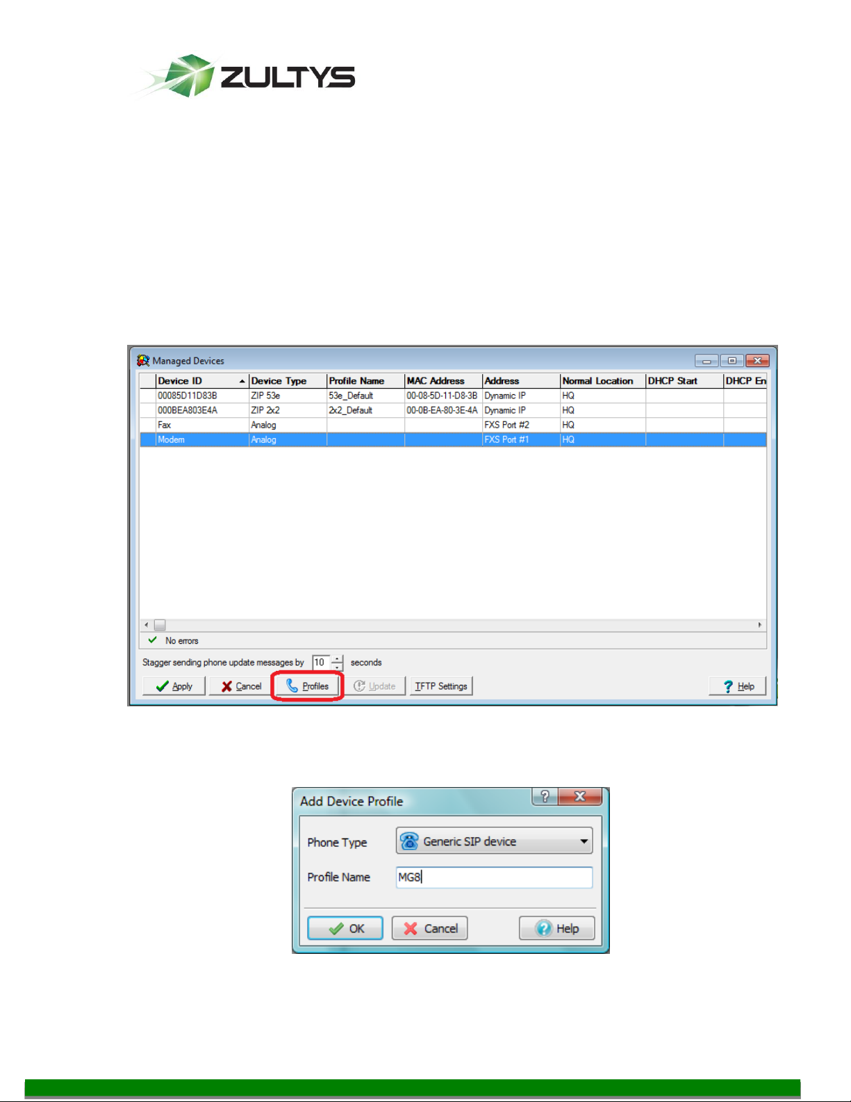
3.2.1 Create new Generic SIP Profile
Before creating devices for Gateway from the Manage Device screen click the
Profiles button, and create a new Generic SIP profile.
From the dropdown select Generic SIP device, and give the profile a unique name.
MG Series Gateway Setup Manual ver 306.X (0000000272)
Revision 20 Jul. 12, 11
© 2011 Zultys, Inc. No reproduction of distribution without permission
Page 4 of 42
Page 5
Technical Publications
Click the OK button.
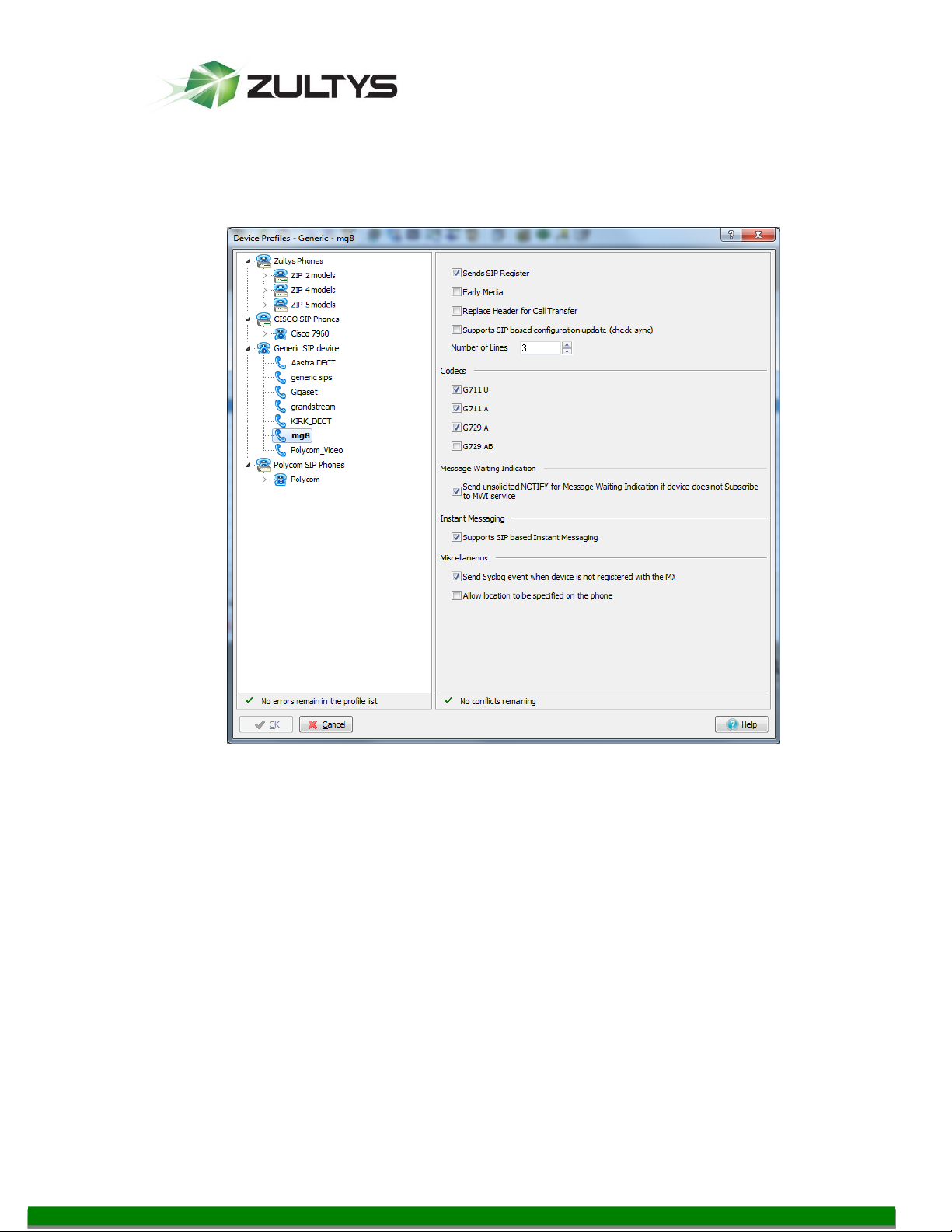
Recommended Settings:
Sends SIP Registration
G711 Codec (G729 is optional)
Send Syslog event when device is not registered with the MX
Send unsolicited NOTIFY for Message Waiting Indication if device does not
Subscribe to MWI service
Click OK.
MG Series Gateway Setup Manual ver 306.X (0000000272)
Revision 20 Jul. 12, 11
© 2011 Zultys, Inc. No reproduction of distribution without permission
Page 5 of 42
Page 6
Technical Publications
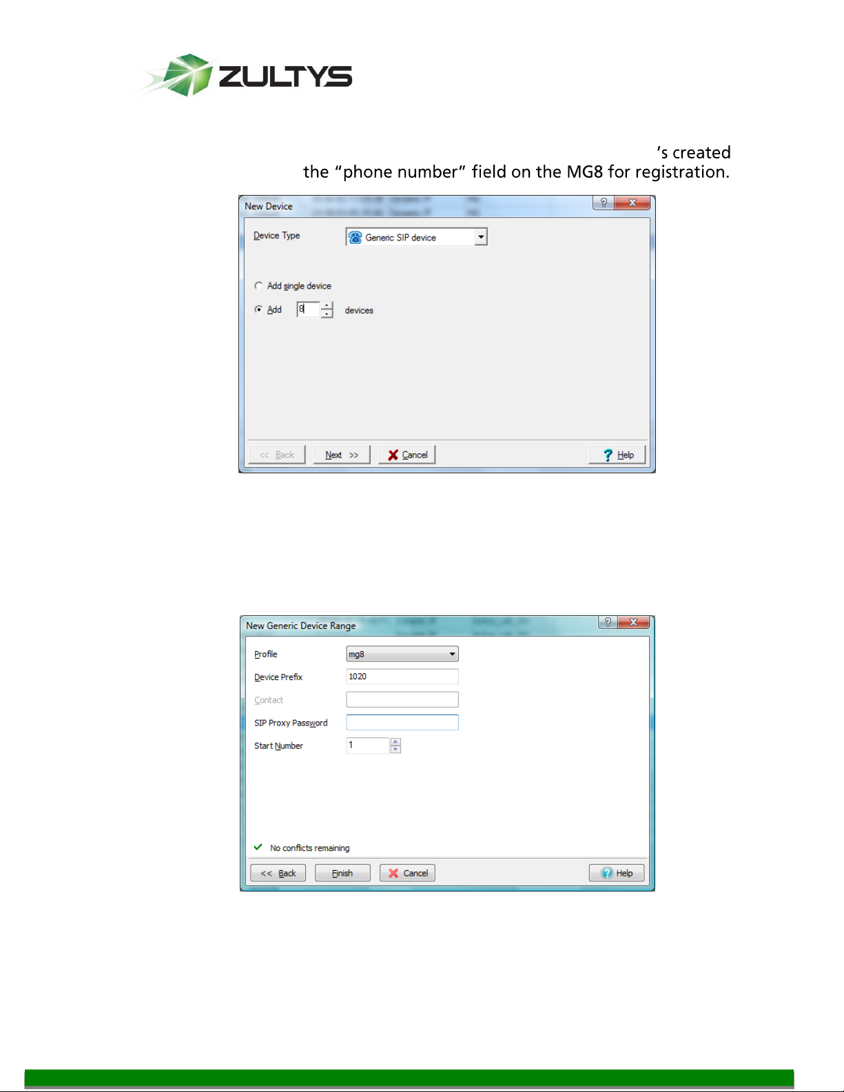
3.2.2 Create Devices
Create the same number of devices the gateway can support. By default the
gateway will register ALL ports, even if not being used. The device ID
here should be used in
Select Generic SIP device
Add all available ports that are supported by the device
Click Next
Select the Profile created
MG Series Gateway Setup Manual ver 306.X (0000000272)
Revision 20 Jul. 12, 11
© 2011 Zultys, Inc. No reproduction of distribution without permission
Page 6 of 42
Page 7
Technical Publications
Device Prefix will be the starting digits of the device name (in this example
we are creating device names of 10201 to 10204).
SIP proxy Password is optional
o The password is required for each device if the MX configured to have
Start Number (1 in this example)
Click Finish
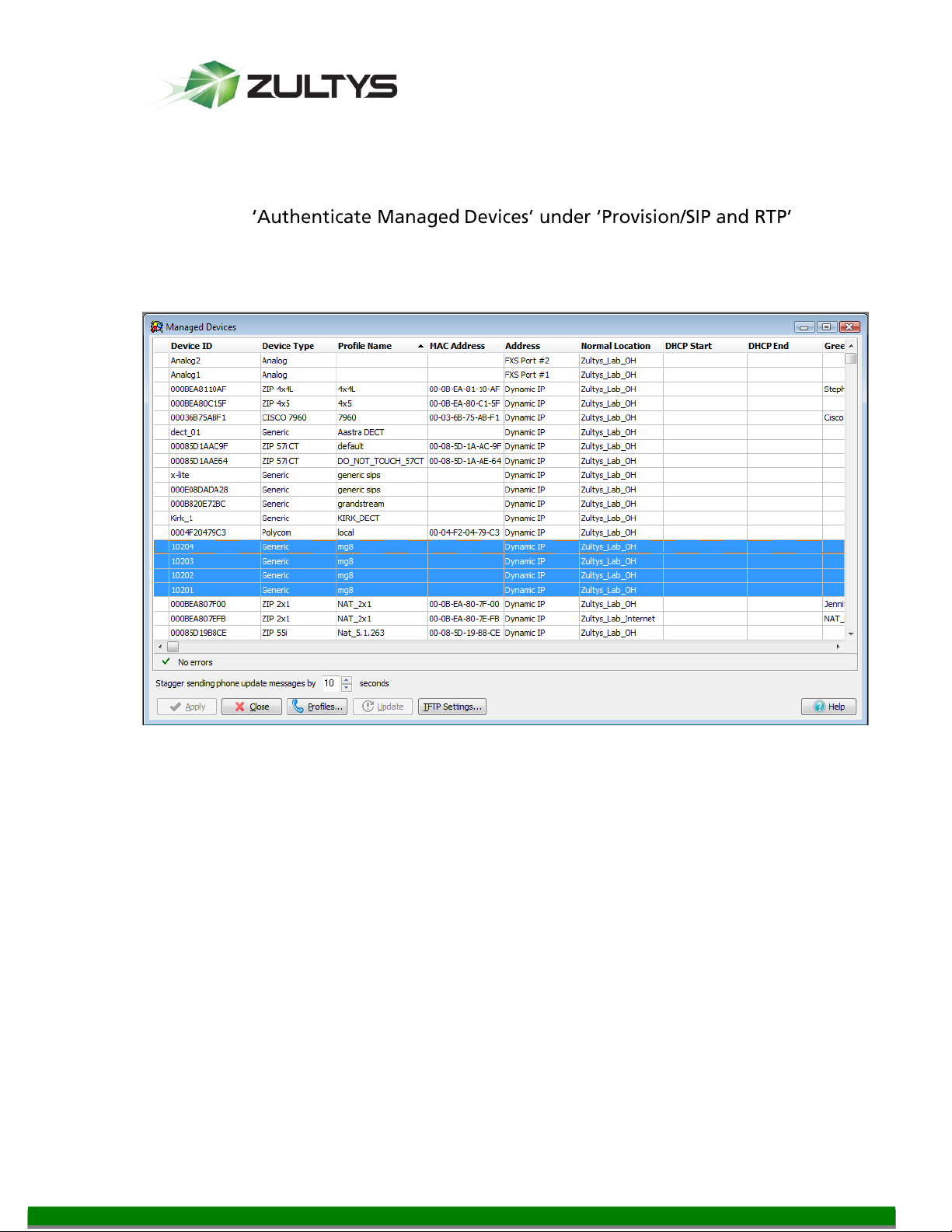
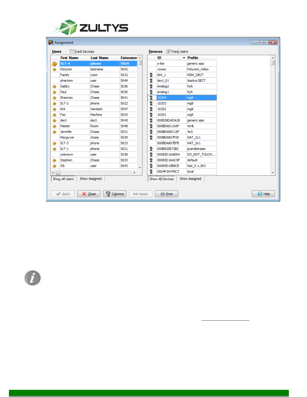
3.2.3 Assign Users to devices
Assign users to the devices.
MG Series Gateway Setup Manual ver 306.X (0000000272)
© 2011 Zultys, Inc. No reproduction of distribution without permission
Revision 20 Jul. 12, 11
Page 7 of 42
Page 8
Technical Publications
We recommend assigning users to the devices associated with FXS ports of MG
only.
4 Connecting the Computer to MG Gateway
To configure the MG Gateway, use the web interface.
Use the Ethernet cable that comes with the system to connect MG to the network
By default the MG8 uses DHCP and can accept the IP address from DHCP
automatically. If there is no DHCP server on the network, you can use factory
default IP address of 192.168.2.218. After the MG8 is started (when leds stop
flashing), it will repeat the IP address to the first off-hook user; in addition, you can
dial ## from any analog phone connected to the FXS Ports to have the MG play its
IP. If there is only FXO ports use external call and dial ## after been connected.
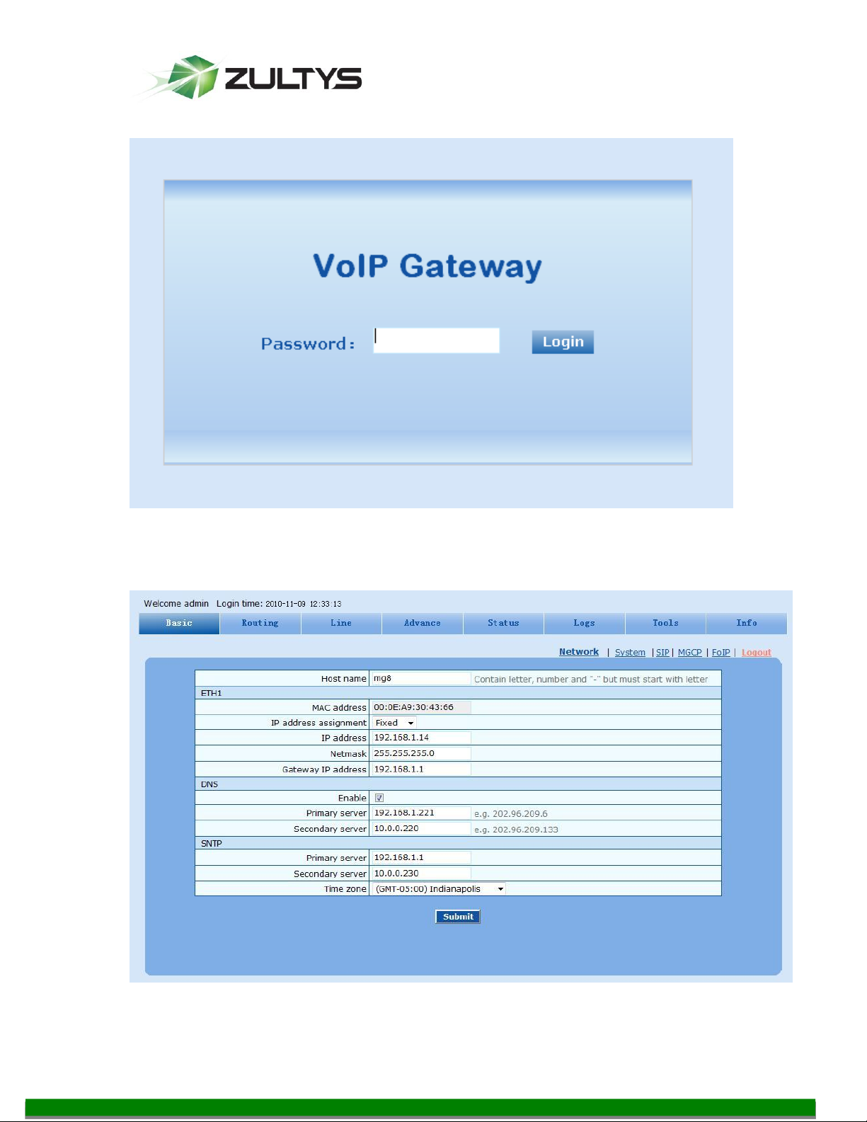
From the PC that is on the same network as MG8, open Internet Explorer, no other
browsers are supported at this time. Enter the gateway IP address in the Address
field (for example, 192.168.2.218). On the login page enter the gateway password
(the default password is voip, which can be changed on the page Changing
Password), and you enter the web configuration interface.
MG Series Gateway Setup Manual ver 306.X (0000000272)
Revision 20 Jul. 12, 11
© 2011 Zultys, Inc. No reproduction of distribution without permission
Page 8 of 42
Page 9
Technical Publications
MG Series Gateway Setup Manual ver 306.X (0000000272)
Revision 20 Jul. 12, 11
© 2011 Zultys, Inc. No reproduction of distribution without permission
Page 9 of 42
Page 10

Technical Publications
Models
Number of FXS
Ports
Number of FXO
Ports
MG8-4S
4
0
MG8-8S
8
0
MG8-4FXO
0
4
MG8-8FXO
0 8 MG8-4S/4
4
4
#
Description
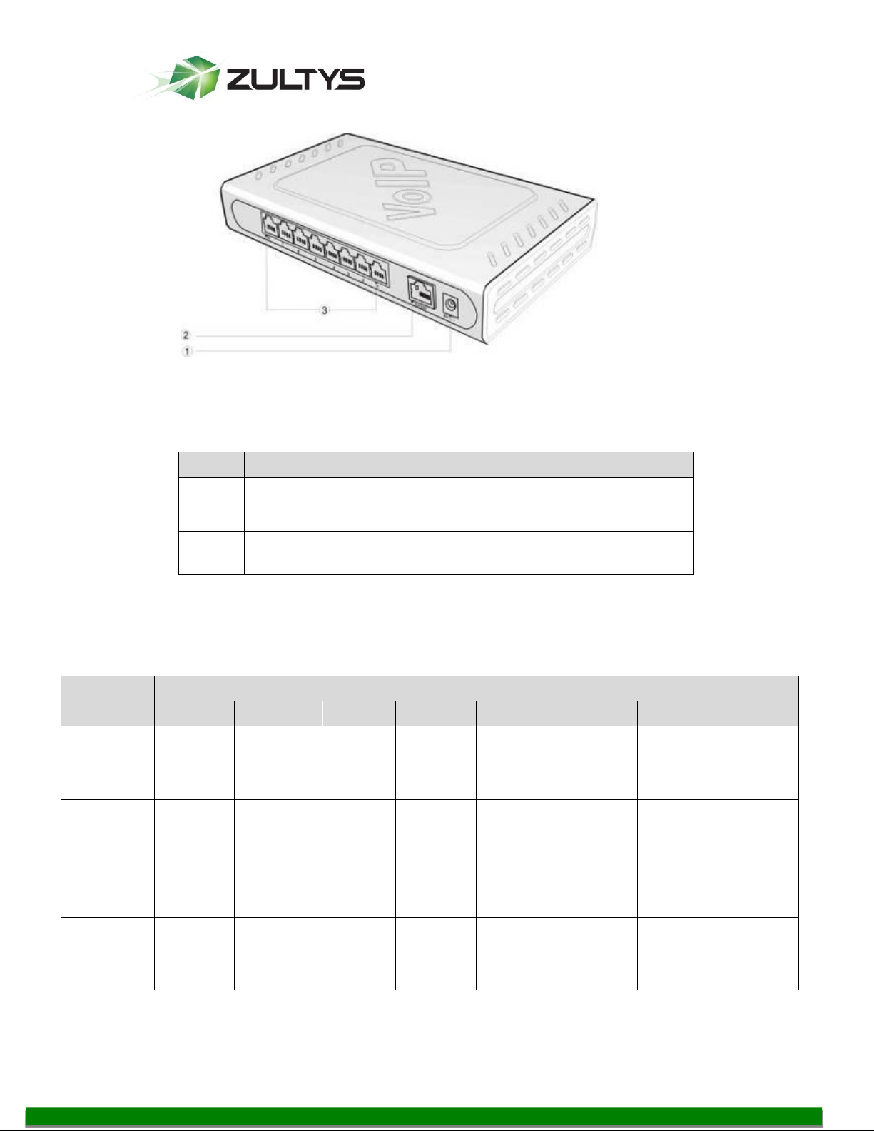
①
Power indicator (PWR), the light on indicates that it has
been powered.
②
Ethernet interface indicator (ETH), the light on indicates
successful connection, the light flashing indicates that data
packets are being received or sent.
③
Analog subscriber line (FXS) or analog trunk (FXO)
interface indicator, the light on indicates that it is in use.
5 Configuration of MG8
The MG8 has a small plastic structure for desktop placement; the MG8 can provide
up to 8 analog line interfaces. MG8 supports the following types of configuration:
5.1 MG8 Front Panel
5.1.1 Description of MG8 Front Panel
MG Series Gateway Setup Manual ver 306.X (0000000272)
© 2011 Zultys, Inc. No reproduction of distribution without permission
Revision 20 Jul. 12, 11
Page 10 of 42
Page 11
Technical Publications
#
Description
①
Power interface, 5-9 VDC input
②
10/100 M Ethernet Interface, RJ45
③
Analog subscriber line (FXS) or analog trunk (FXO)
interface
MG 8
Models
RJ11 Interface Configuration
1 2 3 4 5 6 7
8
MG 8-4S
Subscrib
er Line 1
Subscrib
er Line 2
Subscrib
er Line 3
Subscrib
er Line 4
NA
NA
NA
NA
MG 8-8S
Subscrib
er Line 1
Subscrib
er Line 2
Subscrib
er Line 3
Subscrib
er Line 4
Subscrib
er Line 5
Subscrib
er Line 6
Subscrib
er Line 7
Subscrib
er Line 8
MG8-4FO
Trunk
Line 1
Trunk
Line 2
Trunk
Line 3
Trunk
Line 4
NA
NA
NA
NA
MG 88FXO
Trunk
Line 1
Trunk
Line 2
Trunk
Line 3
Trunk
Line 4
Trunk
Line 5
Trunk
Line 6
Trunk
Line 7
Trunk
Line 8
5.2 MG8 Back Panel
5.2.1 Description of MG8 Back Panel
5.3 Configuration Description of Analog Line Interfaces for All MG8
Models
MG Series Gateway Setup Manual ver 306.X (0000000272)
Revision 20 Jul. 12, 11
© 2011 Zultys, Inc. No reproduction of distribution without permission
Page 11 of 42
Page 12

Technical Publications
MG 8
Models
RJ11 Interface Configuration
1 2 3 4 5 6 7
8
MG 8-4S/4
Subscrib
er Line 1
Subscrib
er Line 2
Subscrib
er Line 3
Subscrib
er Line 4
Trunk
Line 1
Trunk
Line 2
Trunk
Line 3
Trunk
Line 4
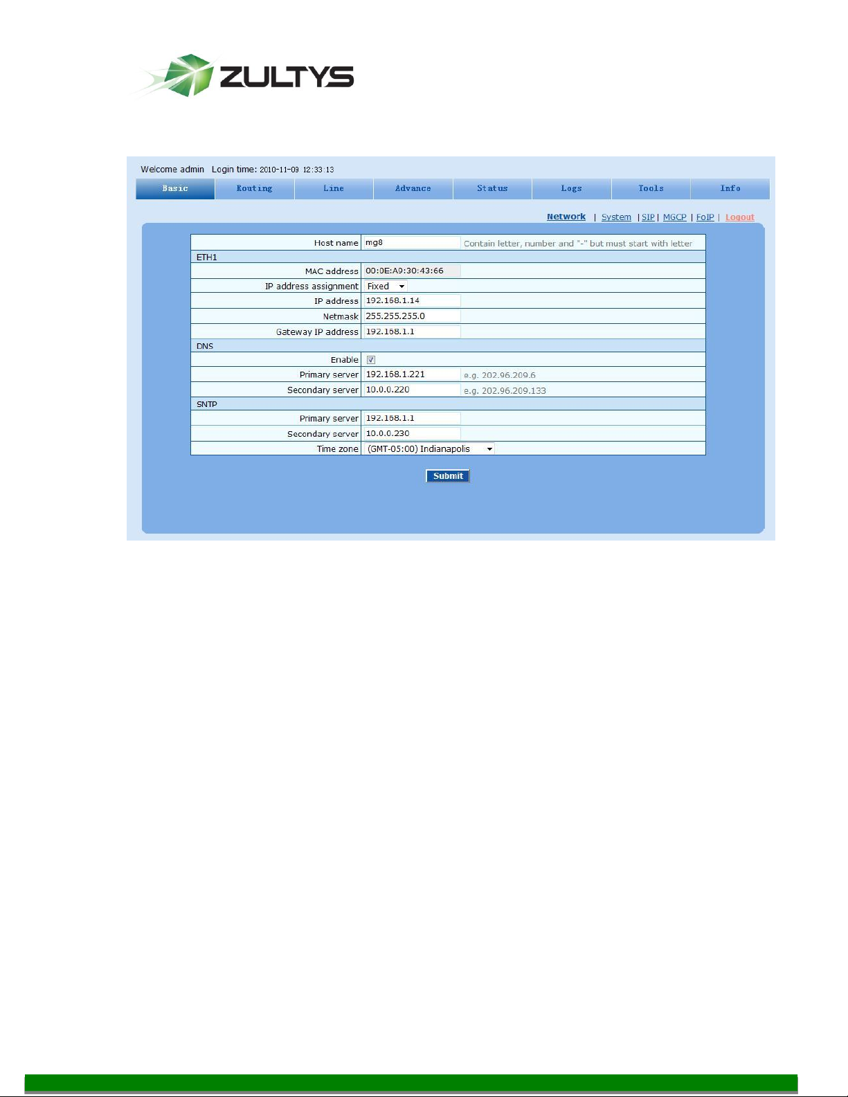
6 Basic Settings
Basic settings are where you set the IP addressing and SIP Registrations settings. SIP
registration settings for the FXS/FXO port MUST be set LAST, to prevent the MX
from blocking the IP address of the MG8. If the IP address is blocked by the MX (a
syslog event will be generated) you must restart them MX to remove this block.
MG Series Gateway Setup Manual ver 306.X (0000000272)
Revision 20 Jul. 12, 11
© 2011 Zultys, Inc. No reproduction of distribution without permission
Page 12 of 42
Page 13
Technical Publications
6.1 IP addressing
Click on the Basic button and then click on the Network link.
Recommended Settings
Host Name: Optional to change from the default
IP Address assignment: Fixed
DNS : Enabled
Primary Server: Populate with correct server
Secondary Server: Optional
SNTP: The IP of the MX
Time zone: Select appropriate Time Zone
Requires a system reboot, or you can make all the changes first and finish with a
system reboot at a later time.
MG Series Gateway Setup Manual ver 306.X (0000000272)
Revision 20 Jul. 12, 11
© 2011 Zultys, Inc. No reproduction of distribution without permission
Page 13 of 42
Page 14

Technical Publications
6.2 System Settings
Click the System link.
Recommended Settings
Hook-flash handle: Internal
DTMF: RFC 2833 (required, MX only supports RFC 2833)
2833 payload type: 101 (required, or DTFM may not function)
Codec: G729A/20, PCMU/20
o If you are using the MG for faxing, you MUST use PCMU/20 ONLY
The rest can be left Default
Click Submit, and requires a restart.
MG Series Gateway Setup Manual ver 306.X (0000000272)
Revision 20 Jul. 12, 11
© 2011 Zultys, Inc. No reproduction of distribution without permission
Page 14 of 42
Page 15

Technical Publications
Name
Description
First digit
timer
parameter after offhook, the gateways will consider that the subscriber
has given up the call and prompt to hang up in busy tone. Unit: second;
Default value: 12 seconds.
Inter-digit
timer
dialing the last number key to the set time by this parameter, the
gateways will consider that the subscriber has ended dial-up and call out
the dialed number. Unit: second; Default value: 12 seconds.
Critical digit
timer
This parameter is used with the "x.T" rule set in dialing rules. For
example, there is "021.T" in the dialing rules table. When a subscriber
this parameter (eg. 5 seconds), the gateways will consider that the
subscriber has ended dial-up and call out the dialed number 021.
Unit: second; Default value: 5 seconds.
Codec
Codecs methods supported by the gateways include G729A/20,
G723/30, PCMU/20, PCMA/20, iLBC/30 and GSM/20 (as shown in
table 2-5). This parameter must be set due to no default value.
Several encoding methods can configure in this item at the same time,
platform in the order from front to back when configuring the codec
methods
Hook-flash
handle
The gateways provide the following processing modes after detecting
hook flash from subscriber terminals: processing the hook flash
internally; transmitting the hook flash to platform with RFC 2833, and
transmitting the flash-off to platform with SIP INFO.
DTMF method
Transmission modes of DTMF signal supported by the gateways include
Audio, RFC 2833 and SIP INFO. The default value is Audio.
Audio: DTMF signal is transmitted to the platform with sessions;
SIP INFO: Separate DTMF signal from sessions and transmit it to the
platform in the form of SIP INFO messages;
RFC 2833: Separate DTMF signal from sessions and transmit it to the
platform through RTP data package in the format of RFC2833.
2833 payload
type
value of 2833 payload type is 100. The effective range available: 96 ~
127. This parameter should match the setting of far-end device (eg.
platform).
DTMF on-time
This parameter sets the on time (in ms) of DTMF signal sent from FXO
port. The default value is 100 ms. Generally, the duration time should be
set in the range of 80 ~ 150 ms.
MG Series Gateway Setup Manual ver 306.X (0000000272)
© 2011 Zultys, Inc. No reproduction of distribution without permission
Revision 20 Jul. 12, 11
Page 15 of 42
Page 16

Technical Publications
Name
Description
DTMF off-time
This parameter sets the off time (ms) of DTMF signal sent from FXO
port. The default value is 100 ms. Generally, the interval time should be
set in the range of 80 ~ 150 ms.
DTMF
detection
threshhold
Minimum duration time of effective DTMF signal. Its effective range is
32-96 ms and the default value is 48 ms. The greater the value is set, the
more stringent the detection is.
6.3 Advanced Settings Media Stream
Recommended settings:
Min.RTP port 20000
Max.RTP port 20999
TOS bits 0x2E
The rest can be left as default
MG Series Gateway Setup Manual ver 306.X (0000000272)
© 2011 Zultys, Inc. No reproduction of distribution without permission
Revision 20 Jul. 12, 11
Page 16 of 42
Page 17

Technical Publications
6.4 Basic Settings FoIP
.
Recommended Settings:
Support Audio Only and T.38 and Voice-band Data and then
select Audio Only . With this selection, MG supports T.30 fax protocol
only, which use audio for fax data transmission. This selection will instruct
the MG not to offer T.38 fax in any way.
The rest can be left Default
Click Submit
6.5 Set the tones to US
Set the tones to United States on Advanced | Tones
MG Series Gateway Setup Manual ver 306.X (0000000272)
Revision 20 Jul. 12, 11
© 2011 Zultys, Inc. No reproduction of distribution without permission
Page 17 of 42
Page 18

Technical Publications
6.6 Set Caller ID transmit
Set the Caller ID Transmit settings to
FSK
MDMF (allows for passing of name and number)
After Ringing
Without Parity
MG Series Gateway Setup Manual ver 306.X (0000000272)
Revision 20 Jul. 12, 11
© 2011 Zultys, Inc. No reproduction of distribution without permission
Page 18 of 42
Page 19
Technical Publications
Name
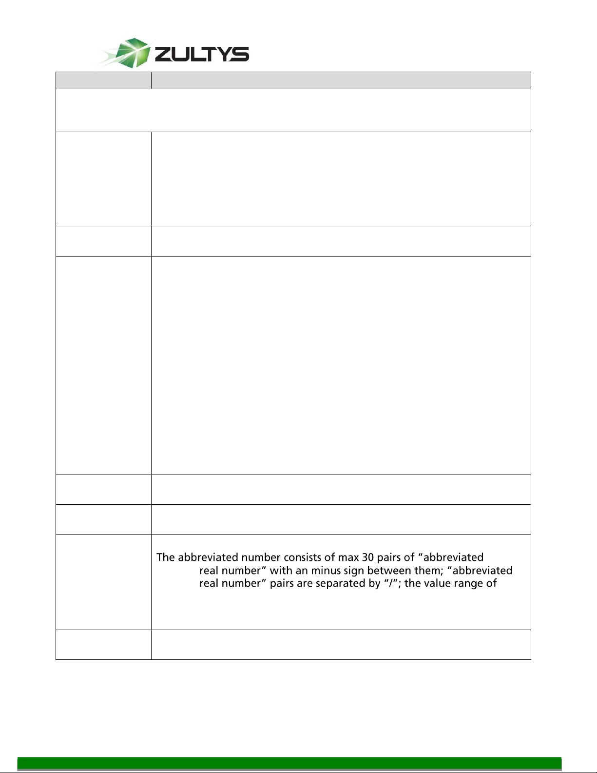
Description
FXS 1st line No.
This number is used for the batch setup of consecutive number of
number of Line 1 adopts initial number; that of Line 2 increases 1
if you do not use batch configuration or the number is not
consecutive.
ID n
Fill in the generic SIP device ID associated with the subscriber line n
(FXS port). This should be manually performed if Batch mode is not
used.
7 FXS Settings
Use the generic SIP devices you created earlier.
7.1 Setup the Prefix
Enter in the starting number and click Batch, the system will automatically
increment for all available ports.
Those IDs correspond to Generic devices created in MX
You set up the prefix for all the FXS lines on the Phone Number page.
MG Series Gateway Setup Manual ver 306.X (0000000272)
© 2011 Zultys, Inc. No reproduction of distribution without permission
Revision 20 Jul. 12, 11
Page 19 of 42
Page 20

Technical Publications
The following is a sample setting for your reference. You need to click the Submit
button for these settings to go into effect.
8 Set up the FXS Line (Features)
From the Line tab, click the Feature link.
8.1 You set up the FXS line on the FXS Configuration page.
Recommended Settings
Phone Number: this is the registration name. It will be the Device ID.
Registration: Yes (checked)
Password: Blank (If filled should correspond to the password of the Generic
device created on MX)
Call waiting: Checked
CID on call waiting: Checked
Call Hold: Checked
Caller transfer: Checked
Caller ID Display: Checked
Subscribe MWI: Unchecked, allows the MG to subscribe to the MX for
Message notification.
The reaming options are left default unchecked
Click Submit to submit the changes
MG Series Gateway Setup Manual ver 306.X (0000000272)
Revision 20 Jul. 12, 11
© 2011 Zultys, Inc. No reproduction of distribution without permission
Page 20 of 42
Page 21

Technical Publications
Name
Description
Line ID
-
for selected line - indicates the current selected subscriber line number and m indicates the
total number of subscriber lines.
Phone number
Display the device ID FXS phone
Registration
Select if this line is required to register with MX. This is selected as
default.
Password
password for register of this line here.
Click Feature Batch to assign the parameters to all FXS Ports
Click Submit, requires a reboot
MG Series Gateway Setup Manual ver 306.X (0000000272)
© 2011 Zultys, Inc. No reproduction of distribution without permission
Revision 20 Jul. 12, 11
Page 21 of 42
Page 22
Technical Publications
Name
Description
Note: The following features are valid only in SIP protocol. When the gateways use MGCP
protocol, features are controled by the proxy server without the need of setting on
gateways.
Hot line
Select if the gateways are required to automatically dial out the hotline
number after off hook. By default, hot line is disabled.
Disable hot line: Close this feature.
Hot line: Automatically dial out the hotline number after off hook.
Delayed hot line: Automatically dial out the hotline number after off
hook is timeout with a time delay of 5 seconds.
Hot line
number
After the hotline function is activated on this line, the hotline number
must be entered here.
CRBT
CRBT stands for Color Ring Back Tone. Set if CRBT is activated, that is,
provide prepared audio package as ring back tone. Note: it is required to
set the CRBT file download platform. This is not selected by default.
MX8 and M100 support two CRBT storage modes: on-system (stored in a
flash memory) and run-time download (from FTP server). The capacity of
both modes are described as follows:
On-system:
MX8: No more than 20 seconds in G.729 format (fring1.dat)
MX100: Up to 20 tone files, a maximum of 400 seconds in G.729 format
or 50 seconds in G.711 format.
Run-time download:
MX8/MX100: Up to 20 tone files, a maximum of 10000 seconds in G.729
format or 1250 seconds in G.711 format.
Note: Tone files are stored in the flash memory and the gateways
automatically download the tone files from FTP server after power on.
CRBT ID
Set the CRBT number with a valid rang of 0~255, where 0 indicates
disabling CRBT. The default value is 0.
Speed dials
Select if the Speed dials is activated on this line. By default, this is not
selected.
Speed dial list
If the Speed dials is activated on this line, enter the speed dials list.
numbernumberabbreviated number is 20 ~ 49. For example: 20-61202700/2313052475522/30-96961. Users can set the list on a telephone set and
display it here.
Call
forwarding
Select if Call Transfer is activated on this line. By default, it is not
selected.
MG Series Gateway Setup Manual ver 306.X (0000000272)
Revision 20 Jul. 12, 11
© 2011 Zultys, Inc. No reproduction of distribution without permission
Page 22 of 42
Page 23

Technical Publications
Name
Description
CFU
If it is required to forward all incoming calls unconditionally, enter the
new destination number here.
CFNR
If it is required to forward an incoming call when there is no answer,
enter the new destination number here.
CFB
If it is required to forward an incoming call when it is busy, enter the new
destination number here.
Forking
Select if the Forking is activated. Forking allows the gateway to initiate a
call to another telephone terminal while ringing on this line terminal and
the answer by either terminal will end up with ringing of the other
terminal.
Forking
number
If forking of this line is activated, set a number for the second ringing
terminal here. The ringing terminal can be another port of gateways or
an external terminal such as mobile phone.
Release
control by
caller
Select if the call release is controlled by the caller. By default, this is not
selected.
Selected: The gateway will immediately release the call upon caller
hanging up; the gateway will not release the call as long as the caller is
still off until timeout (60 seconds by default);
Unselected: The gateway will immediately release the call upon either
party hanging up the call.
Call waiting
Select if Call waiting is activated on this line. By default this is not
selected.
CID on call
waiting
Select if Caller ID Display is activated on this line during call waiting. By
default, this is not selected.
Call hold
Select if Call Hold is activated on this line. By default this is not selected.
Note:
If this function is activated, the gateways will automatically activate Call
Transfer (Either party may transfer the current call to a third party).
Caller Transfer
Select if Caller Transfer is activated on this line. By default, this is not
selected. When A calls to B, B picks up the call and transfers the call to C,.
Note: The call hold must be activated before caller transfer.
Caller ID
display
Set if Caller ID display is activated on this line. By default, this is selected.
Note: In addition to number display, the Caller ID can display the names
of incoming calls as long as terminal equipment support.
Caller ID
restriction
Set if the number of this telephone is sent to the called party. By default
this is not selected.
Outgoing call
barring
Select if outgoing calls are barred on this line. By default, this is not
selected.
MG Series Gateway Setup Manual ver 306.X (0000000272)
© 2011 Zultys, Inc. No reproduction of distribution without permission
Revision 20 Jul. 12, 11
Page 23 of 42
Page 24
Technical Publications
Name
Description
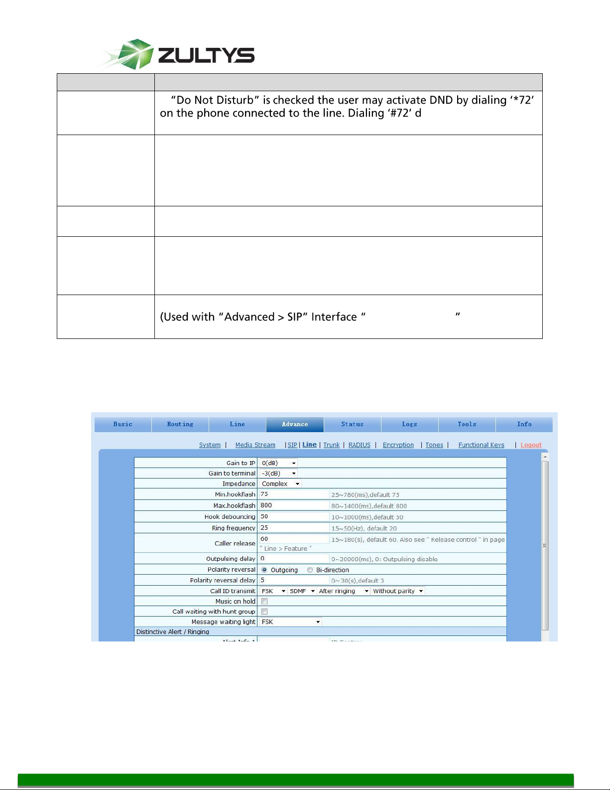
DND
If
eactivate DND state of
the line. By default DND is disabled.
Direct Dialing
in (DDI)
Set if DDI (Direct Dialing In) is activated, By default this is not selected.
Different from FXS, DDI is only used for incoming calls, and the gateways
will not send dial tone after off-hook (calling in) on user side.
Note: Reverse polarity signal must be activated on the gateways when
DDI is used.
Maintenance
Select if the line is set to maintenance status, namely, stop to supply of
power for the line port. By default, this is not selected.
Polarity
reversed signal
Select if reverse polarity signal is activated on this line. By default, this is
not selected.
Note: The gateways will provide reverse polarity signal when the phone
is connected after this feature is activated.
Subscribe MWI
Select if voice mail service is activated, and by default this is not selected.
MWI subscription
Configuration)
8.2 Advanced features of the FXS port
The advanced features of the FXS port are configured under Advance Line
MG Series Gateway Setup Manual ver 306.X (0000000272)
© 2011 Zultys, Inc. No reproduction of distribution without permission
Revision 20 Jul. 12, 11
Page 24 of 42
Page 25
Technical Publications
Name
Description
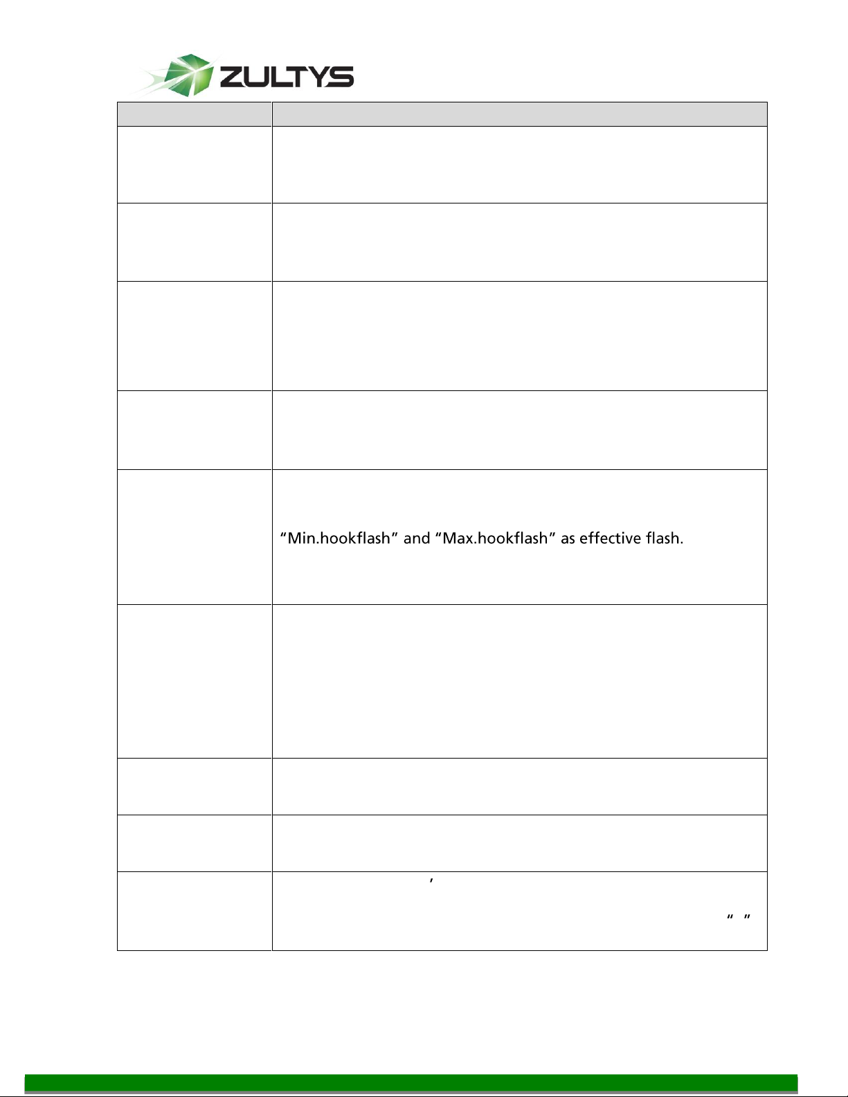
Gain to IP
Set the voice volume gain towards IP side, the default is 0. Taking
decibel as the unit, setting range is -3 ~ +3 decibels. -3 means
declining of 3 decibels; +3 denotes the amplification of 3 decibels.
Gain to terminal
Set the voice volume gain towards FXS port side, the default is -3.
Taking decibel as the unit, setting range is -6 ~ +3 decibels. -3
means declining of 3 decibels; +3 denotes the amplification of 3
decibels.
Impedance
Select the parameter of FXS port line impedance and the default
value is 600 ohm. The optional values as below:
Complex
600(ohm)
900(ohm)
Min.hookflash
Used by gateway to detect Hook Flash event, the default is 75
milliseconds. The gateway will ignore any flash that fall short of
the shortest flash time. Generally, this value should not be less than
75 milliseconds.
Max.hookflash
Used by gateway to detect hook flash, the default is 800
milliseconds.
The gateway will regard the flash duration between
Any flash
lasting over the longest time will be considered by gateway as
hang up. Generally, this value should not be less than 800
milliseconds.
Hook debouncing
Used by gateway to avoid the glitch of the phone status, with
default of 50 milliseconds.
When the duration from hang-up to off-hook falls short of this
value, the gateway will ignore the status variation, and consider
the phone remains hang-up status. In case of vice versa, the
gateway will ignore the status variation, and consider the phone
remains off hook status. Effective range of setting is 10~1000
milliseconds.
Ring frequency
Set the ringing frequency to be transmitted by gateway to the
phone, ranging from 15 to 50 Hz, with default of 20 Hz.
Caller release
Set the delay release time of line as caller control method, with
default of 60 seconds. Effective range of setting is 15~180 seconds.
Outpulsing delay
Used when gateways FXS port is connected with the trunk
interface of PBXs. For calls from gateway to PBX, gateways will
relay the extensions to PBX after the delay set here. Setting of 0
means no extension number relay. The default is 0 millisecond.
MG Series Gateway Setup Manual ver 306.X (0000000272)
© 2011 Zultys, Inc. No reproduction of distribution without permission
Revision 20 Jul. 12, 11
Page 25 of 42
Page 26

Technical Publications
Name
Description
Polarity reversal
Set the trigger for polarity reversal
Outgoing: Transmit reverse polarity signal only when the
outbound is connected;
Bi-direction: Transmit reverse polarity signal for the
connection of both inbound and out bound calls.
Polarity reversal
delay
The delay time from call being answered to the transmission of
reverse polarity signal. The default value is 3 in seconds. Effective
range of setting is 0 ~ 30 seconds.
Call ID transmit
Select transmission mode of Caller ID signal from the FXS port to
the phone.
FSK or DTMF;
SDMF or MDMF;
Sending Caller ID data before or after ringing;
Sending Caller ID data with or without parity.
Music on hold
Choose whether to play the background music while call waiting,
and the default is not to play.
Call waiting with
hunt group
Choose whether to activate hunt group feature for call waiting,
Default not selected.
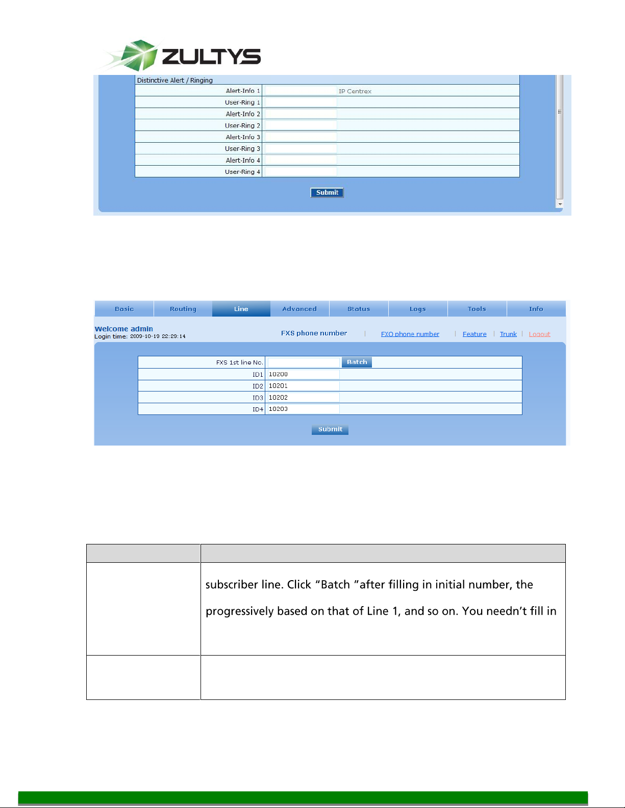
Message waiting
light
Choose the lighting method of message waiting indicator of voice
mail here: None, Polarity reversed, FSK. Message waiting indicator
refers to the special LED on a phone, working with voice mail
function. When user gets the latest mail, the gateway will light this
lamp upon receiving the notice from platform; the light goes off
when the user well received all the
understand whether the phone supports the indicators and
lighting method when selecting the lighting method.
9 Create SIP Trunk from Zultys to MG
This SIP Trunk to the MG8 is used to allow calls from the MG8 to the MX and will
be used to place FXO calls out of the MG8.
9.1 Create SIP Trunk on MX
MG Series Gateway Setup Manual ver 306.X (0000000272)
© 2011 Zultys, Inc. No reproduction of distribution without permission
Revision 20 Jul. 12, 11
Page 26 of 42
Page 27

Technical Publications
Recommended Settings:
Type: External
Address: IP Address or FQDN of the MG Gateway
The rest can remain the default settings
10 FXO Settings
Calls placed from the MX to the MG8 will arrive on the SIP trunk created earlier.
The MG8 routing table will control calls leaving the MG8 to the PSTN.
10.1 If the MG8 has FXO lines, you need to set them up on the FXO Configuration page.
MG Series Gateway Setup Manual ver 306.X (0000000272)
Revision 20 Jul. 12, 11
© 2011 Zultys, Inc. No reproduction of distribution without permission
Page 27 of 42
Page 28

Technical Publications
Name
Description
Recommended Settings:
Unique Identifiers for each trunk, correspond to Generic SIP devices created
on MX
10.2 FXO Line configuration
Recommended settings:
Phone Number: Unique Identifier per trunk
Registration: Unchecked
Inbound Handle: Binding
Binding Number: A DID of the user/call group/auto attendant on the MX
that all incoming calls will ring to
Call ID Detection: Checked
Echo cancellation: Checked
Click submit to save changes
Click Trunk Batch to copy to remaining FXO lines
MG Series Gateway Setup Manual ver 306.X (0000000272)
Revision 20 Jul. 12, 11
© 2011 Zultys, Inc. No reproduction of distribution without permission
Page 28 of 42
Page 29

Technical Publications
Trunk ID
- the
-
- indicates the current selected trunk number and m indicates the total
number of trunks.
Phone number
Display device ID
Registration
Select if this trunk registers with the SIP registration server. By default,
this is selected.
Password
The authentication password for register of this line must be entered
here corresponding to the password set for the same device ID on MX.
Note: The following features are valid only in SIP protocol. When the gateways use MGCP
protocol, the control of all call services is provided by the proxy server without the need of
setting.
Inbound handle
The gateways provide two scenarios for handling incoming calls of
FXO port:
port, the gateways will provide the second dial tone and route the
call according to the extension number pressed in. Note: dialing
tone or voice prompt file can be changed by user.
gateways will route the call to a FXS port according to the DID
number bound with the port. Note: Setting a number to be bound is
required or this setting is invalid.
Polarity reversed
signal detection
If a PSTN line supports reverse polarity, make a selection here. Or this
setting is invalid. By default, this is not selected.
Caller ID
detection
Select if the detection function of caller ID for this FXO port is
enabled. By default, this is selected.
Outgoing call
barring
Select if this FXO port bars outgoing call service to PSTN. By default,
this is not selected.
Echo cancellation
Select if echo cancellation is enabled for this FXO line. By default, this
is selected.
Connect signal
delay
After making an outgoing call from a FXO port, the gateway will send
a 200 OK message to the platform with delay if this parameter is
selected. If unselected, the system sends a 200 OK message to the
platform after off hook on the FXO port. Used with the configuration
10.3 Advanced FXO settings
Suggested settings are
Caller ID detection mode: After ringing A
MG Series Gateway Setup Manual ver 306.X (0000000272)
© 2011 Zultys, Inc. No reproduction of distribution without permission
Revision 20 Jul. 12, 11
Page 29 of 42
Page 30

Technical Publications
Title
Explanation
Gain to IP
Set the voice volume gain towards IP side, the default is 0. Taking
decibel as the unit, setting range is -3 ~ +9 decibels. -3 means declining
of 3 decibels; +3 denote the amplification of 3 decibels.
Gain to PSTN
Set the voice volume gain towards PSTN side, the default is -3. Taking
decibel as the unit, setting range is -6 ~ +9 decibels.
Impedance
Set the parameter of FXO line impedance, with the default of 600
ohm. The optional settings as below:
Complex
600(ohm)
Outpulsing Delay: 600
Busy|Repeat: 30 (allow at least 30 cycles of busy tone for outgoing call
before disconnecting the line)*
The rest as defaults
MG Series Gateway Setup Manual ver 306.X (0000000272)
© 2011 Zultys, Inc. No reproduction of distribution without permission
Revision 20 Jul. 12, 11
Page 30 of 42
Page 31

Technical Publications
900(ohm)
Outpulsing delay
The time interval between FXO going off-hook and starting outpulsing
the first digit to PSTN. The default is 400 in milliseconds.
Ring relay
Whether to relay the ring of inbound call to the FXS port when
Busy line handle
Either a voice prompt or hanging up can be applied to FXO port when
an incoming call goes to the FXS port which is in busy. This applicable
only to DID feature.
PSTN failover
PSTN failover: if checked then when network connection from MG to
MX fails, MG tries to reroute the call. The recommended routing is
included in suggested routing table
Caller ID
detection modes.
Before ringing A
Before ringing B
After ringing A (set for US)
After ringing B
Inbound first
digit timeout
Set the timeout of calling DTMF on FXO port for inbound calls, ranging
from 10-60 seconds, with default of 24 seconds.
Answer delay
Set the delay time of outbound connection ranging from 10-60
Line >T
Connect signal delay
Off-hook for
rejection
Used for binding a FXO port with a FXS port. For inound calls to a FXO
port, if the FXS port which binging with the FXO port is in the state of
busy line, the gateway will hang up after hook off according to the
time set by the parameter, so as to refuse the upcoming call. The
duration of off hook is 500~5000 milliseconds, with default of 600
milliseconds.
On-hook
protection time
Protection period following hang up of FXO port. During this period,
gateway ignores any voltage variation of line. Value range is 100~5000
milliseconds, the default is 400 in milliseconds.
Polarity
detection.
Choose whether to activate the detection of reverse polarity signal of
FXO port inlet. Note the detection will work only when the trunk
supports polarity reversal.
Busy Detection
Repeat
Gateways will regard the busy tone signal with the repeat times
specified here as hang-up signal. Default is 2, values range from 2 to
40. *The web interface needs to be corrected to reflect this change
On-time
Set duration of busy tone signal, the default is 350 in milliseconds.
Off-time
Set the interval time of busy tone, the default is 350 in milliseconds.
MG Series Gateway Setup Manual ver 306.X (0000000272)
© 2011 Zultys, Inc. No reproduction of distribution without permission
Revision 20 Jul. 12, 11
Page 31 of 42
Page 32

Technical Publications
11 Routing
The routing table in the MG8 is used to route traffic between the MX
andMG8ports.
11.1 Digit Map
Recommended patterns, (where extensions on MX are 5000 to 5999)
This will allow calling Voice Mail, Park Server, Page Server, Blind Transfer Code, dial
internal extensions, and external calls.
*77xx
*4xx
*38
*86
#xx
5xxx*
x.T
x.#
#xx
##
*1
MG Series Gateway Setup Manual ver 306.X (0000000272)
Revision 20 Jul. 12, 11
© 2011 Zultys, Inc. No reproduction of distribution without permission
Page 32 of 42
Page 33
Technical Publications
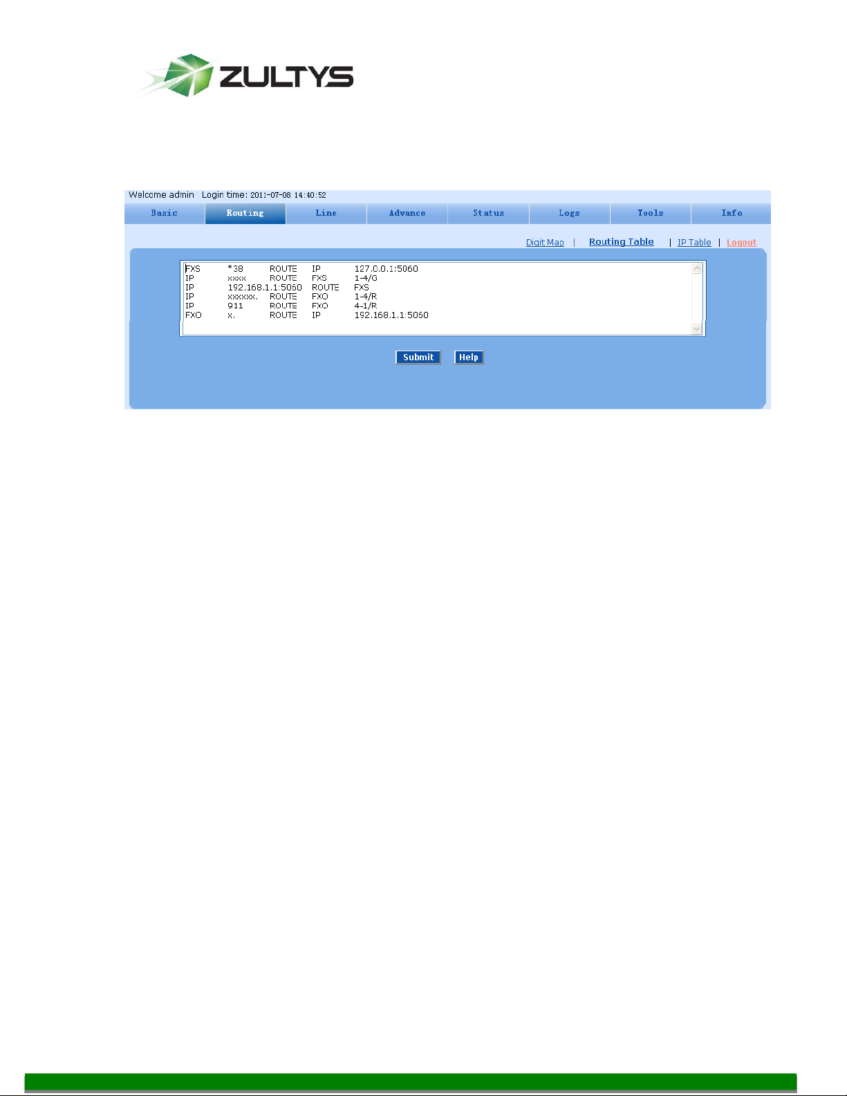
11.2 Routing Table
Recommended settings: (where 192.168.1.1 is the IP Address of the MX)
FXS *38 ROUTE IP 127.0.0.1:5060
IP xxxx ROUTE FXS 1-4/g
IP 192.168.1.1:5060 ROUTE FXS
IP xxxxxx. ROUTE FXO 1-4/R
IP 911 ROUTE FXO 4-1/R
FXO x. ROUTE IP 192.168.1.1:5060
The above settings will allow
1. Blind transfer by doing a hook flash on the FXS and dialing *38 , wait for the
tone and then dial the transfer number
2. In a fail over situation (no IP connection to the MX) calls from the FXO lines
will ring all 4 FXS ports simultaneously
3. Calls from the MX to the FXS ports on the MG8
4. Calls from the MX to the MG8 that are 6 digits and longer are to be routed
to the PSTN (FXO) starting from port 1 to port 4 in a Round Robin manner.
5. Calls from the MX to the MG8 that are the exact match to 911 are to be
routed to the PSTN (FXO) starting from port 4 to port 1 in a Round Robin
manner.
6. Calls from the FXO ports to be sent to the MX
Calls from the FXS to the MX are handled by the registration/proxy process.
MG Series Gateway Setup Manual ver 306.X (0000000272)
Revision 20 Jul. 12, 11
© 2011 Zultys, Inc. No reproduction of distribution without permission
Page 33 of 42
Page 34

Technical Publications
Routing Table Format
Name
Description
Source
There are three types of source: IP, FXS and FXO.
Among them, IP source can be any IP address and is denoted by
“IP”; “IP [xxx.xxx.xxx.xxx]” is used to denote specific IP address; “IP
[xxx.xxx.xxx.xxx: port]” is used to denote specific IP address with
port number.
FXS and FXO ports can be any port, represented with “FXS” or “FXO”;
special lines can be represented with FXS or FXO + port number, eg.
FXS1, FXO2 or FXS [1-2], etc.
Number
It should be a calling number with the form of CPN + number or a
called number with the form of number. The number may be denoted
with digit 0-9,"*",".","#"," x ", etc., and uses the same regular
expression as that of dialing rules. Examples:
Designate a specific number: eg.114,61202700;
Designate a number matching a prefix: such as 61xxxxxx. Note: the
matching effect of 61xxxxxx is different from that of 61x or 61.
Specify a number scope. For example, 268[0-1,3-9] specifies any
4-digit number starting with 268 and followed by a digit between 01or 3-9;
Note: Number matching follows the principle of “minimum matching”.
For example: x matches any number with at least one digit; xx
matches any number with with at least two-digit; 12x matches any
number with at least 3-digit starting with 12.
Processing Mode
Description and Example
KEEP
Keep number. The positive number behind KEEP means to keep
several digits in front of the number; the negative number means to
keep several digits at the end of the number.
Example: FXS 02161202700 KEEP -8
Keep the last 8 digits of the called number 02161202700 for calls from
FXS. The transformed called number is 61202700.
REMOVE
Remove number. The positive number behind REMOVE means to
remove several digits in the front of the number; the negative number
means to remove several digits at the end of the number.
For example: FXS 021 REMOVE 3
Remove 021 of the called number beginning with 021 for calls from
FXS.
Number Transformations
MG Series Gateway Setup Manual ver 306.X (0000000272)
© 2011 Zultys, Inc. No reproduction of distribution without permission
Revision 20 Jul. 12, 11
Page 34 of 42
Page 35
Technical Publications
Processing Mode
Description and Example
ADD
Add prefix or suffix to number. The positive number behind ADD is
the prefix; the negative number is suffix.
Example 1:
FXS1 CPNX ADD 021
FXS2 CPNX ADD 010
Add 021 in front of calling numbers for calls from FXS port 1; add 010
in front of calling numbers for calls from FXS port 2.
Example 2:
FXS CPN6120 ADD -8888
Add 8888 at the end of the calling number starting with 6120 for calls
from FXS port.
REPLACE
Number replacement. The replaced number is behind REPLACE.
Example: FXS CPN88 REPLACE 2682000
Replace the calling number beginning with 88 for calls from FXS port
to 2682000.
REPLACE
Other use of REPLACE is to replace the specific number based on
other number associated with the call. For example, replacing the
calling number according to the called number.
Examples:
FXS 12345 REPLACE CPN-1/8621
FXS CPN13 REPLACE CDPN0/0
For calls from FXS ports with called party number of 1234, removing
one digit at the rear of the calling number and add 8621; for call s
from FXS ports with calling party number starting with 13, add 0 in
front of the called number.
MG Series Gateway Setup Manual ver 306.X (0000000272)
© 2011 Zultys, Inc. No reproduction of distribution without permission
Revision 20 Jul. 12, 11
Page 35 of 42
Page 36
Technical Publications
Processing Mode
Description and Example
END or ROUTE
End of number transformation. From top to bottom, number
transformation will be stopped when END or ROUTE is encountered;
the gateways will route the call to the default routing after meeting
EDN, or route the call to the designed routing after meeting ROUTE.
Example 1:
FXS 12345 ADD -8001
FXS 12345 REMOVE 4
FXS 12345 END
Add suffix 8001 to the called number starting with 12345 for calls
from FXS ports, then remove four digits in front of the number to end
number transformation.
Example 2:
IP[222.34.55.1] CPNX. REPLACE 2680000
IP[222.34.55.1] CPNX. ROUTE FXS 2
For calls from IP address 222.34.55.1, calling party number is
replaced by 2680000, and then the call is routed to FXS port 2 with
the new calling party number.
CODEC
Designate the use of codec, such as PCMU/20/16, where PCMU
denotes G.711, /20 denotes RTP package interval of 20 milliseconds,
and /16 denotes echo cancellation with 16 milliseconds window.
PCMU/20/0 should be used if echo cancellation is not required to
activate.
Example:
IP 6120 CODEC PCMU/20/16
PCMU/20/16 codec will be applied to calls from IP with called party
number starting with 6120.
RELAY
Insert prefix of called party number when calling out. The inserted
prefix number follows behind REPLAY.
Example:
IP 010 RELAY 17909
For calls from IP with called party number starting with 010, digit
stream 17909 will be pulsed out before the original called party
number being sending out.
Destination
Description and Example
ROUTE NONE
Calling barring.
Example:
IP CPN[1,3-5] ROUTE NONE
Bar all calls from IP, of which the calling numbers start with 1, 3, 4, 5.
Routing Destination
MG Series Gateway Setup Manual ver 306.X (0000000272)
© 2011 Zultys, Inc. No reproduction of distribution without permission
Revision 20 Jul. 12, 11
Page 36 of 42
Page 37

Technical Publications
Destination
Description and Example
ROUTE FXS
Route a call to FXS ports.
Example 1:
IP 800[0-3] ROUTE FXS 1,2,3,4
Select FXS port in a sequential way.
Example 2:
IP 800[0-3] ROUTE FXS 1
Point this call to FXS port 1.
Example 3:
IP 800[0-3] ROUTE FXS 1,2,3,4/g
For terminating the call from IP, ring FXS port 1, 2, 3, 4 simultaneously.
ROUTE FXO
Route a call to FXO port.
Example:
IP x ROUTE FXO 1,2,3,4/r
Select the outgoing call FXO port in a round robin way.
ROUTE IP
Route a call to the IP platform.
Example:
FXS 021 ROUTE IP 228.167.22.34:5060
228.167.22.34:5060 is the IP address of the platform.
MG Series Gateway Setup Manual ver 306.X (0000000272)
© 2011 Zultys, Inc. No reproduction of distribution without permission
Revision 20 Jul. 12, 11
Page 37 of 42
Page 38
Technical Publications
Name
Description
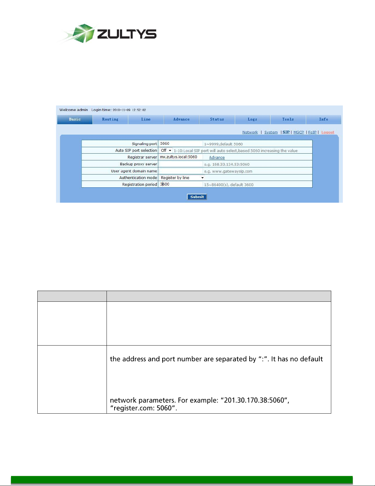
Signaling port
Configure the UDP port for transmitting and receiving SIP messages,
with its default value 5060.
Note: The signaling port number can be set in the range of 1-9999,
but cannot conflict with the other port numbers used by the
equipment.
Register server
Configure the address and port number of SIP register server, and
value.
The register server address can be an IP address or a domain name.
When a domain name is used, it is required to activate DNS service
and configure DNS server parameters on the page of configuring
12 SIP protocol Settings
SIP protocol Settings are on the Basic tab and click on the SIP link.
12.1 You need to set up three parameters on the SIP Configuration page.
Recommended Settings:
Signaling port: 5060
Registrar server: IP Address or FQDN of the MX:5060
Proxy Server: IP Address or FQDN of the MX:5060
Authentication mode: Register by line
Registration period: 3600
MG Series Gateway Setup Manual ver 306.X (0000000272)
© 2011 Zultys, Inc. No reproduction of distribution without permission
Revision 20 Jul. 12, 11
Page 38 of 42
Page 39

Technical Publications
Name
Description
Proxy server
Configure the IP address and port number of SIP proxy server, and
value.
The proxy server address can be set to an IP address or a domain
name. When a domain name is used, it is required to activate DNS
service and configure DNS server parameters on the page of
configuring network parameters. Examples of complete and
effective configuration: "201.30.170.38:5060", "softswitch.com:
5060".
Backup proxy
server
Configure the IP address and port number of backup proxy server. It
has no default value. Add the address of calling proxy server here,
and the gateways can support selection function of multiple
softswitch addresses through IP address. The format must be IP
address format and complete and effective configuration, eg.
identical.
Conditions for falling over to the backup proxy server (any):
1)Gateway register is timeout;
2)No response to master server calls is timeout;
User agent
domain name
This domain name will be used in INVITE messages. If it is not set
here, the gateways will use the IP address or domain name of proxy
server as user agent domain name. It has no default value.
It is recommended that subscribers not use LAN IP address to set
domain name parameter.
Authentication
mode
The gateway support three registration scheme: register per line,
register per gateway and Line Reg/GW Auth. The default value is
register by line.
Register by line: authentication and register per line;
Register by gateway: authentication and register per gateway;
Line Reg/GW Auth: register per line, but authentication per
gateway.
User name
Configure the user name as part of the account for registration, and
it has no default value.
MG Series Gateway Setup Manual ver 306.X (0000000272)
© 2011 Zultys, Inc. No reproduction of distribution without permission
Revision 20 Jul. 12, 11
Page 39 of 42
Page 40
Technical Publications
Name
Description
Password
Password as part of account information is used for authentication
by platform. It has no default value. It is formed with either numbers
or characters, and case sensitive.
the password
Registration
period
Valid time of SIP re-registration in second.
13 Additional Options
To enable additional settings you will need to use Internet Explorer, and enter
custom http urls in the Address window.
13.1 Enable Busy Tone Detection for FXO
To enable Busy Tone Detection for FXO
URl: http://xx.xx.xx.xx/xml?method=gw.config.set&pass=voip&id235=zzz
For US the zzz recommended value is 480 (for use in the US set value to 480
which is the busy tone frequency in US)
To view the current value:
http://xx.xx.xx.xx/xml?method=gw.config.get&pass=voip&id=235
13.2 Battery Denial Timing Disconnect for FXO
The minimal timing of consistent battery denial detected on FXO port to recognize
such condition
URl: http://xx.xx.xx.xx/xml?method=gw.config.set&pass=voip&id205=400
The recommended value is 400 ms
To view the current value:
http://xx.xx.xx.xx/xml?method=gw.config.get&pass=voip&id=205
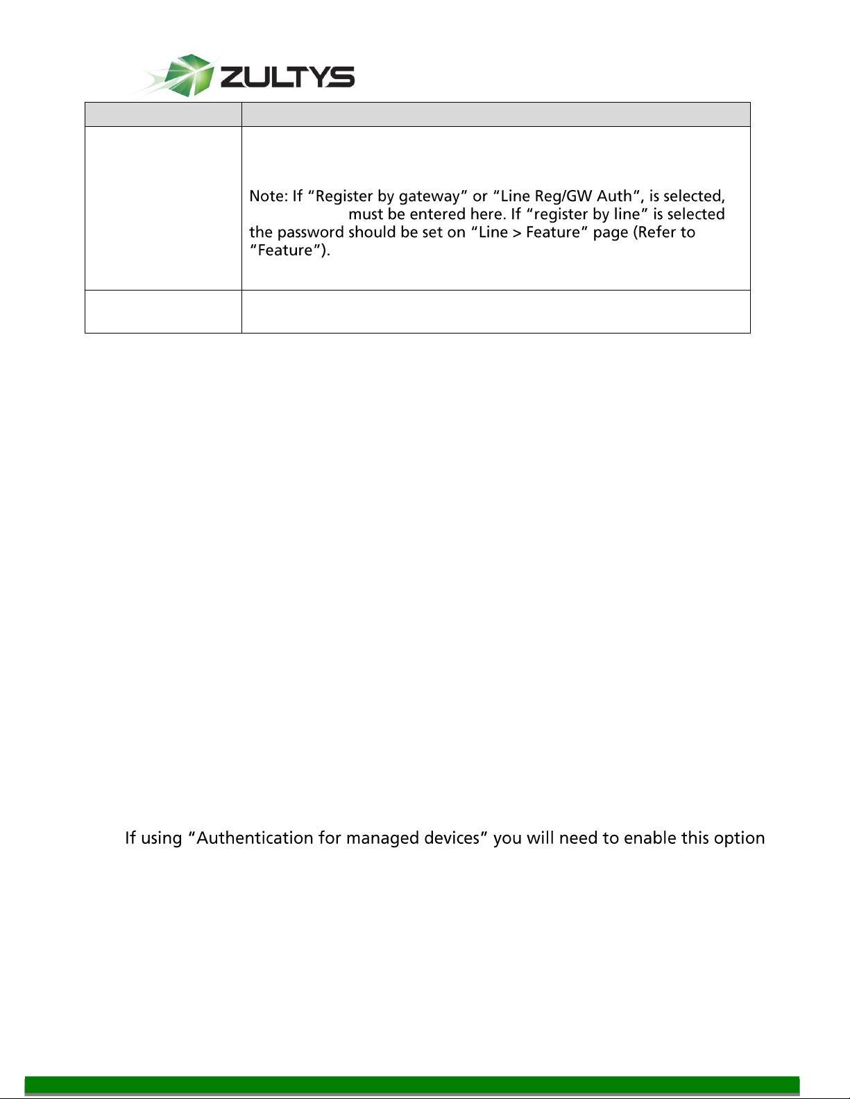
13.3 Using Authentication for Managed devices
on the MG to guarantee that the FXS ports disconnect properly.
URl: http://xx.xx.xx.xx/xml?method=gw.config.set&pass=voip&id638=yes
Read back the current value:
http://xx.xx.xx.xx/xml?method=gw.config.get&pass=voip&id=638
MG Series Gateway Setup Manual ver 306.X (0000000272)
© 2011 Zultys, Inc. No reproduction of distribution without permission
Revision 20 Jul. 12, 11
Page 40 of 42
Page 41

Technical Publications
13.4 Silence after disconnect (FXS ports)
This option allows switching silence on FXS Ports after
receiving disconnect from the other side. The silence is used with special paging
devices, which disconnect on silence.
To set silence as disconnect indication enter
URI: http://xx.xx.xx.xx/xml?method=gw.config.set&id603=1
To set busy tone as disconnect indication enter
URI: http://xx.xx.xx.xx/xml?method=gw.config.set&id603=0
To read back the current value:
http://xx.xx.xx.xx/xml?method=gw.config.get&pass=voip&id=603
The setting affects all FXS ports
14 Fail Over
14.1 SIP Failure between the MG and the MX
In the event SIP communications is lost between the MG and the MX, incoming
calls can be routed to the FXS Ports via the Routing Table. The recommended entry
is
IP xxxx ROUTE FXS 1-4/g
This will route all incoming calls that have that are exactly 4
digits in length to FXS Ports 1-4 simultaneously.
or shorter than
section.
14.2 Power Fail MG8SO (4FXO/4FXS)
In the event of a power failure for the MG8SO (which has 4 FXS Ports, and 4 FXS
Ports).
section.
FXO Port 1 will be relay switched to FXS Port 1
FXO Port 2 will be relay switched to FXS Port 2
FXO Port 3 will be relay switched to FXS Port 3
FXO Port 4 will be relay switched to FXS Port 4
MG Series Gateway Setup Manual ver 306.X (0000000272)
Revision 20 Jul. 12, 11
© 2011 Zultys, Inc. No reproduction of distribution without permission
Page 41 of 42
Page 42

Technical Publications
15 Troubleshooting
This section covers basic troubleshooting areas of the MG.
15.1 Outgoing on calls on FXO fail to connect.
Try to e Out Pulsing De from 400 ms to longer time (600-1000 ms.
This will extend the time from going off hook on the FXO before sending out the
first DTMF tone. This can be done on the Advanced Tab | Trunk page.
15.2 Blank SIP messages are being sent to the MX from the MG
To st
MX, disable NAT Transversal, on the Advanced Tab | System page.
15.3 MWI Lights are not set correctly
Change the MWI Subscription time from once every 24 hours (86400) to once an
hour (3600 seconds). This can be done under the Advanced Tab | SIP page.
15.4 DNS information is incorrect after updating a DNS server
DNS is cached on the MG and is only updated on a reboot. This can be modified by
Zultys Technical Support.
15.5 Local 3 way conferencing of the FXS port on the MG does not work by default
Local conferencing is disabled by default and can be enabled by Zultys Technical
Support.
MG Series Gateway Setup Manual ver 306.X (0000000272)
Revision 20 Jul. 12, 11
© 2011 Zultys, Inc. No reproduction of distribution without permission
Page 42 of 42
 Loading...