

Page 1

ZTE CORPORATION
NO.55,Hi-techRoadSouth,ShenZhen,P.R.China
Postcode:518057
Tel: (86) 755 26771900 800-9830-9830
Fax: (86) 755 26772236
URL: http://support.zte.com.cn
E-mail:
doc@zte.com.cn
ZXV10 B760E
RichMedia Box
User Guide
1
Page 2

LEGAL INFORMATION
Revision No.
Revision Date
Revision Reason
R1.0
2014–05–22
First
Copyright © 2012 ZTE CORPORATION.
All rights reserved.
No part of this publication may be excerpted, reproduced, tra nsla ted or ut iliz e d in
any form or by any means, electronic or mechanical, including photocopying and
microfilm, without the prior written permission of ZTE Corporation.
The manual is published by ZTE Corporation. We reserve the right to make
modifications on print errors or update specifications without prior notice.
History Revision
Serial No.: SJ-20140522095238-001
2
Page 3

FCC Statement
This equipment has been t e ste d and fou nd t o co mp ly with the limits for a Cla ss B
digital device, pursuant to part 15 of the FCC Rules. T hese li mit s ar e d esi gne d to
provide reasonable protection again st har mf ul inter fer en ce in a residentia l
installation. This equipment generates, uses and can radiate radio frequency
energy and, if not installed and used in accordance with the instructions, may
cause harmful interference to radio communications. However, there is no
guarantee that interference will not occur in a particular installation. If this
equipment does cause harmful interference to radio or television reception,
which can be determined by turning the equipment off and on, the user is
encouraged to try to correct the interference by one or more of the following
measures:
—Reorient or relocate the receiving antenna.
—Increase the separation between the equipment and receiver.
—Connect the equipment into an outlet on a circuit different from that to which
the receiver is connected.
—Consult the dealer or an experienced radio/TV technician for help.
FCC Radiation Exposure Statement
This device complies with FCC radiation exposure limits set forth for an
uncontrolled environment a nd it als o co mpl ies w it h Part 15 of the FCC RF Rules.
This equipment must be installed and operated in accordance with provided
instructions and the antenna(s) used for this transmitter must be installed to
provide a separation distance of at least 20 cm from all persons and must not be
co-located or operating in conjunction with any other antenna or transmitter.
End-users and installers must be provide with antenna installation instructions
and consider removing the no-collocation statement.
This device complies with Par t 15 of the FC C R ules. Operation is sub ject t o the
following two conditions: (1) this device may not cause harmful interference,
and (2) this device must accept any interference received, including interf er en ce
that may cause undesired operation.
Caution!
Any changes or modifications not expressly approved by the party
responsible for compliance could void the user's authority to operate the
equipment.
3
Page 4

Content
Chapter 1 Safety Instructions ............................................... 1
Chapter 2 Packing List ...................................................... 2
Chapter 3 Panels ............................................................... 3
3.1 Front Panel .......................................................................................... 3
3.2 Rear Panel ........................................................................................... 3
3.3 Side Panel ........................................................................................... 4
Chapter 4 Connecting Up................................................... 4
4.1 Connecting Network ............................................................................ 4
4.2 Video and Audio Connections ............................................................. 5
4.2.1 Connecting Standard Definition Interface ................ 5
4.2.2 Connecting High Definiti on Interface ........................ 6
4.2.3 Connecting Digital Audio .......................................... 7
4.3 Power ON ............................................................................................ 8
4.4 Upgrade ............................................................................................... 8
Chapter 5 Remote Control ................................................. 9
5.1 STB Remote Control ............................................................................ 9
5.2 Key Customization ............................................................................. 10
Chapter 6 Operation Guide .............................................. 11
6.1 Standby/Working Status .................................................................... 11
6.2 EPG Operations................................................................................. 11
6.3 Common Operations During Watching Programs .............................. 12
6.4Controlling Program Playing ............................................................... 13
6.5 Watching TSTV Program ................................................................... 14
Chapter 7 Troubleshooting ............................................... 15
Chapter 8 Technical Specification .................................... 17
4
Page 5

Chapter 1 Safety Instructions
Special Note
• Remove the plastic covering before using the Set-Top Box to provide normal
ventilation.
• Use the power adapter provided with the Set-Top Box.
Important Safety Instructions
• Ensure that the electric voltage meets the device requirements. Check the
cables periodically, replace any damaged cabl es im mediat e l y .
• To prevent electric shock, do not remove cover. There are no user serviceable
parts inside. Refer servicing to qualified service.
• Do not use this apparatus near water.
• Clean with only dry cloth.
• Place the device on a flat surface. Do not place any heavy objects on the
device.
• Do not block any ventilation openings. Install according to the manufacturer’s
instructions.
• Do not install near any heat sources, such as radiators, heat registers, stoves,
or other apparatus (including amplifiers) that produce heat.
• Only use attachments/accessories specified by the manufacturer.
• Power off and pull out the power plug if the device will not be used for a long
time and during lightning storms.
• After power off, wait at least 15 seconds between power off and next power-on.
• For the adapter, the socket-outlet shall be installed near the adapter and shall
be easily accessible.
Service
Do not disassemble the device. Contact the service provider if the following
problems occur:
1
Page 6
• The power cable or power socket is damaged.
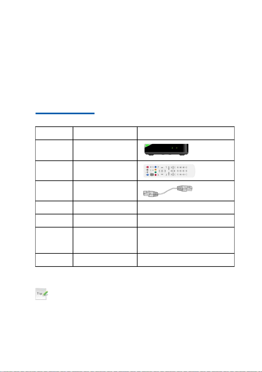
Quantity
Item
Remarks
Set-Top Box (STB)
Remote control
Ethernet network
cable
1
Power adapter
-
1
User Guide
-
Qualification
NTY
1
Packing list
-
• There is any liquid leaks into the device.
• Fails to run normally even after following the instructions.
• The device is physically damaged.
Chapter 2
1
1
1
1
Certificate/WARRA
Packing List
Tips:
This packing list is for reference only. The items actually delivered depend
on the companion packing list of the STB. Contact the provider
immediately if parts are missing or damaged. Keep all packaging and
available components for return purposes.
2
Page 7
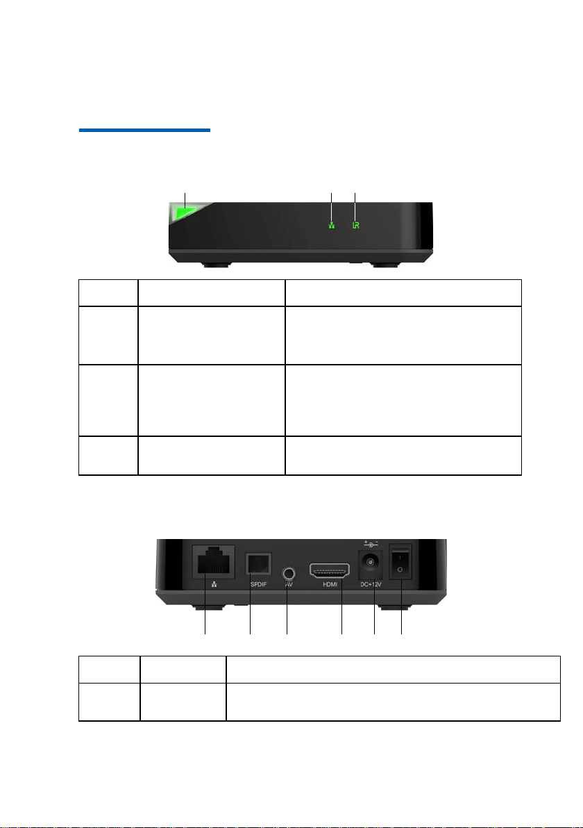
Chapter 3 Panels
1
2 3
Key
Name
Description
Running status indicator
Red: STB is in standby state.
Connection status
Infrar ed indicato r
The green indicator flashes when the STB
receives signals from the remote control.
1 2 3 4 5 6
Key
Name
Description
1
WAN
10/100M Base-T RJ45 ethernet int erface, us ed to connect t o
gateway/xDSL modem.
3.1 Front Panel
1
2
3
indicator
3.2 Rear Panel
Green: STB is running normally
Not Lit: STB is not powered ON
Blinking (Green): the network connection is
normal.
Not Lit: the network connection fails or no
physical connection.
3
Page 8

Key
Name
Description
2
SPDIF
Optical digital audio output interface.
3
AV
Composite video output interface, which c an be used for
connecting to TV's composite video and audio input interface. .
4
HDMI
HDMI output interface.
5
DC+12V
Power input socket, +12 V DC power adapter provided.
Consult technical personnel before using other types of power
6
Power
switch
Make sure th e power switch is turned to I after the STB is powered
on
1
2
Key
Name
Description
1
USB
USB interface.
2
TF
TF card interface.
adapter.
3.3 Side Panel
Chapter 4 Connecting Up
4.1 Connecting Network
This section introduces the network connection methods for STB. Select one
method to connect according to the on-site condition s.
4
Page 9

Phone socket xDSL Modem
STB
TV
Telephone
line
Network
cable
Video/audio
cable
WAN interface
STB
Network
interface
TV
Network
cable
Video/audio
cable
WAN interface
Network
cable
LAN
STB
TV
Video/audio
cable
AP
4.2 Video and Audio Connections
4.2.1 Connecting Standard Definition Interface
Steps
1. Connect the R and L i nterfaces on the TV to the corresponding interfaces
with AV the cables.
2. Connect the VIDEO interface on STB to video input interface of TV with AV
cable (yellow), as shown in the follow figure.
5
Page 10

Power adapter
—END OF STEPS—
4.2.2 Connecting High Definition Interface
Steps
1. Connect the HDMI interface on STB to the corresponding interface on TV with
HDMI cable, as shown in the following figure.
6
Page 11

Power adapter
HDMI
TV set
Power
adapter
To digital audio
amplifier
Note:
HDMI output interface simultaneously generates uncompressed
high-definition video and multi-channel audio data. One HDMI data cable
is capable of conveying both video and audio data.
—END OF STEPS—
4.2.3 Connecting Digital Audio
There is one optical digital audio output interface, connect the S/PDIF interface
on STB to digital audio amplifier for using digital audio.
7
Page 12

4.3 Power ON
Steps
1. Ensure that all cables are connected correctly.
2. Install the power cable to STB using the power adapter and to AC power
source.
3. Ensure that all other devices are plugged in and rec eiving power.
4. Turn on the TV.
—END OF STEPS—
4.4 Upgrade
The STB can connect to the server on each power-on and check whether an
upgrade is required. If so, the upgrade starts at once, which normally takes three
to five minutes. Do not perform any operations during this period.
8
Page 13

Chapter 5 Remote Control
5.1 STB Remote Control
9
Page 14

Note:
The remote control provided depends on the IPTV service provider. The
appearance of remote control shown is for reference only.
Notes:
• The remote control is powered by two AAA batteries. Insert two AAA
batteries into the remote control according to the polarity instruction
displayed on it.
• During the operation, point the front part of the remote control to the
infrared receiving area on the STB.
5.2 Key Customization
There are four TV learning keys on the STB remote control (Power, TV/AV,
VOL+, VOL-) . These four corresponding functions on TV remote control can be
operated on the STB remote control through customization. Users can perform
some operations for both TV and STB by only using the remote control of STB.
1. Press and hold SET key for about 3 seconds until the learning status indicator
turns into solid green, which signals the starting of the learning process.
2. Place the two remote controls.
3. Press the key to be learned on the TV remote control (for example, the Power
key), the learning status indicator changes from solid green to solid red. Then
press the target key on the STB remote control (for example, Power key), the
learning status indicator changes from solid red to solid green, which signals
that the learning process is successful.
4. Follow step 3 to learn other keys.
5. After completing the learning process, do not perform any operations until the
learning status indicator is off, which signals that the learning information is
stored successfully. Or pres s SET key to save the learning set ting and qu it the
learning mode.
10
Page 15

Note:
Press key once to switch STB between the standby and working state.
Press key once to switch TV between the standby and working state.
Use TV/AV key to switch the system mode of TV.
Press Menu key on the remote control to enter the EPG homepage.
Press direction keys (up, down, left, and right) on the remote control to select
When EPG contents are organized in multiple levels or pages, perform a page flipping operation
via the following keys.
Go to the up per level if the current level is not th e t o p-most level .
If the STB remote control fails to control TV after learning, please learn
again following the above steps.
—END OF STEPS—
Chapter 6 Operation Guide
6.1 Standby/Working Status
6.2 EPG Operations
an EPG item (such as button, text box, c olumn).
Press OK key to confirm the selection.
11
Page 16

Go to the previous page if there are multiple pages in the same level.
Go to the ne x t page if ther e are multiple pages in the s ame level.
Use the following keys to switch program mode and open the requested page direc tly.
Go to live TV.
Go to TV On Dem and.
Go to Video-On Demand.
Go to information surfing program.
View program information.
Use the following keys to control the volume.
Switch between different audio modes (left channel, right channel, stereo).
back on.
Raise or l ower the audi o v olume of STB.
Raise or lower the audio volume of TV.
6.3 Common Operations During Wa tching
Programs
Press
key once to the sound off. Press key again to turn the sound
12
Page 17

Use the following keys to switch channels while watching progra ms.
number to directly turn to.
Select the next channel, up and down, when watching TV.
program.
Press key to stop playing the program.
the program.
Press
key display the channel number on the s creen, then enter chan nel
6.4Controlling Program Pla yi ng
When a program is play ing ( su ch a s l iv e T V , VO D , T S T V) , use the fol lowing keys
to control the progress of the program.
Press
Press ke y t o fast forward a Video-On Demand or TSTV program at a
speed of 2X, 4X, 8X, 16X, or 32X.
When the program is fast forwarded to the interested point, press the
to play the program.
Press
at a speed of 2X, 4X, 8X, 16X, or 32X.
When the program is rewind to the interested point, press the
Press
chapters.
When playing a TSTV program, press
key to pause the p rogram; Press key again to resume the
key to rewind when playing a Video-On Demand or TSTV program
key to go to the next chapter. Programs might be organized into
key
key to play
key to exit TSTV and go to live TV.
13
Page 18

When playing a single VOD program, press key to go to the end point of
press OK key to play the program from the interested point.
Press key to display the information of the current channel and program.
Enter TS T V program
program, then press key to play TSTV program.
Press key to go back to the starting point of the TSTV program.
key to adjust the progress of the pr ogram to an int erested poi nt.
the program.
Press
into chapters.
When play ing a TSTV prog ram, press
program.
When playing a single VOD program, press
start point.
Press
direction keys to adjust the progress of the program to an interested point and
key to back to the previous chapter. Progra m s might be organized
key to go to the start point of the
key to play the program from
key to pop up the program prog ress bar, th en use the left and right
6.5 Watching TSTV Program
Users can watch some missed live programs through time-shifted TV service of
STB.
When watc hing live program, press key to enter TSTV
Press key t o p op up the program progress bar, then us e left
14
Page 19

Press OK key to play the TSTV program from the interested point.
Exit TSTV program
Press key to exit TSTV and go back to Live program.
Problem
Possible Cause
Solution
The indicator is
The power adapter has
not been connecte d.
Connect the power adapt er .
The power adapter is
Consult the service
adapter with a new one.
The power outlet has no
power.
Check and ensure the
power outlet has power.
User cannot
The network cable has
properly.
Connect the network cab le
new cable.
The service network
Wait for service to be
service provider.
The network
correct.
Configure the network
No image on the
The STB is in standby.
Turn on STB by pressing
control.
The video cable has not
Reconnect video cable.
Chapter 7 Troubleshooting
not lit after
switching on the
STB.
damaged.
provider and replace power
connect to the
not been connecte d
EPG homepage.
fails.
configurati on is no t
TV screen.
properly or replace it with a
restored or consult the
parameters again.
key on the remote
15
Page 20

Problem
Possible Cause
Solution
been connected properly.
The video input source
incorrectly.
Switch the system mode of
is shown on the TV.
No sound from
the speaker.
The STB is in standby.
Turn on STB by pressing
control.
The audio cable has not
been connected properly.
Reconnect audio cable.
STB or TV is muted, or
TV.
The remote
There is no battery in the
backwards.
Install the batteries
The batteries are dead.
Replace the batteries.
TV cannot receive
Use the remote control
remote control and STB.
The
match the image.
Some video programs are
the audio mode.
Other problems
-
Restart STB or call the
customer service hotl ine.
of the TV has been set
the TV until the EPG page
key on the remote
control fails.
corresponding
sound does not
the volume has been
turned all the way down.
remote control, or the
batteries are install ed
instructions from remote
control.
broadcasted in multiple
audio tracks.
Press key on the
remote control, or increase
the volume of the STB or
correctly.
closer to STB, or remove
any obstacles between the
Press the key on the
remote control to switch
16
Page 21

Chapter 8 Technical Specification
Compliant
Standard
GB4943.1-2011、GB9254-2008、YD/T993-1998
Power Adapter
Input: 100 V ~ 240 V 50Hz/60Hz Output: +12.0 V DC
Environment
Working environment temperature: +32 ℉ ( 0 ℃ ) ~ +104 ℉
( +40 ℃ )
Working environment humidity: 5% ~ 95%
Protocol
TCP/IP, HTML 4.0, HTTP 1.1/JavaScr i pt 1.5 , NTP,FTP,
HTTPS/SSL2.0/3.0
Video
Supports PAL, NTSC, 720p, 1080i, 1080p
Format: 4:3/16:9
Receiving bit rate rang e: 200 Kbps ~ 40 Mbps
Resolution: 720 × 576/PAL, 720 × 480/NTSC, 1280 × 720 /720p ,
1920 × 1080 /1080i, 1920 × 1080 /1080p
Aduio
MPEG1 Lay er 1/2, MPEG1 Layer3(Optional), AAC, Mpeg-2 AAC
LC,Mpeg-4 AAC LC,HE-AAC v1/v2,wav,wma,PCM
Dolby 5.1, Suround,Single/Dual Track,Stereo,
Access Mod e
Supports DHCP,LAN,PPPOE, WLAN access
Supports PPPoE, IEEE 802.11 a/b/g/n, IPV4/IPV6
Dimension
110 mm × 110mm × 25 mm (Length × Wi dth × Height )
Requirement
Manufactured under license from Dolby Laboratories. Dolby and the double-D symbol are
trademarks of Dolby Laboratories.
17
 Loading...