

Page 1

ZXSDRR8860
CDMARemoteRadioUnit-8860
InstallationManual
ZTECORPORATION
ZTEPlaza,KejiRoadSouth,
Hi-TechIndustrialPark,
NanshanDistrict,Shenzhen,
P .R.China
518057
Tel:(86)75526771900
Fax:(86)75526770801
URL:http://ensupport.zte.com.cn
E-mail:support@zte.com.cn
Page 2

LEGALINFORMATION
Copyright©2006ZTECORPORATION.
Thecontentsofthisdocumentareprotectedbycopyrightlawsandinternationaltreaties.Anyreproductionordistributionof
thisdocumentoranyportionofthisdocument,inanyformbyanymeans,withoutthepriorwrittenconsentofZTECORPORATIONisprohibited.Additionally ,thecontentsofthisdocumentareprotectedbycontractualcondentialityobligations.
Allcompany ,brandandproductnamesaretradeorservicemarks,orregisteredtradeorservicemarks,ofZTECORPORA TION
oroftheirrespectiveowners.
Thisdocumentisprovided“asis”,andallexpress,implied,orstatutorywarranties,representationsorconditionsaredisclaimed,includingwithoutlimitationanyimpliedwarrantyofmerchantability ,tnessforaparticularpurpose,titleornon-infringement.ZTECORPORATIONanditslicensorsshallnotbeliablefordamagesresultingfromtheuseoforrelianceonthe
informationcontainedherein.
ZTECORPORATIONoritslicensorsmayhavecurrentorpendingintellectualpropertyrightsorapplicationscoveringthesubject
matterofthisdocument.ExceptasexpresslyprovidedinanywrittenlicensebetweenZTECORPORA TIONanditslicensee,
theuserofthisdocumentshallnotacquireanylicensetothesubjectmatterherein.
ZTECORPORATIONreservestherighttoupgradeormaketechnicalchangetothisproductwithoutfurthernotice.
UsersmayvisitZTEtechnicalsupportwebsitehttp://ensupport.zte.com.cntoinquirerelatedinformation.
TheultimaterighttointerpretthisproductresidesinZTECORPORATION.
RevisionHistory
RevisionNo.RevisionDateRevisionReason
R1.0
08/30/2008FirstEdition
SerialNumber:sjzl20082714
Page 3

Contents
Preface...............................................................i
SafteyDescription.............................................1
SafetySpecicationsGuide..............................................1
SafetySymbols..............................................................2
SafetyInstructions.........................................................3
InstallationOverview........................................7
ComponentstobeInstalled.............................................7
InstallationFlow.............................................................7
InstallationPreparation...................................................8
EngineeringConditionInspection..................................8
ToolsandInstrumentsPreparation................................9
On-siteDocuments...................................................10
UnpackingAcceptance................................................11
CountingGoods................................................11
CrateUnpacking...............................................11
CartonUnpacking.............................................12
AcceptanceandGoodsHandover.........................12
CabinetInstallation.........................................15
EngineeringIndices.......................................................15
InstallationModeInstruction...........................................16
Pole-mountedInstallationMode.......................................17
ComponentsUsedinPole-mountInstallation.................17
InstallingT woZXSDRR8860C806Pole-mountCabinets
(WithoutWaveT rap)..........................................19
InstallingT woZXSDRR8860C806Pole-mountCabinets
(WithWaveT rap)...............................................22
InstallingThreeZXSDRR8860C806CabinetsonPole
(WithoutWaveT rap)..........................................25
InstallingThreeZXSDRR8860C806CabinetonPole
(WithWaveT rap)...............................................27
Wall-mountedInstallationMode.......................................33
Page 4

ComponentsUsedinWall-MountInstallation.................33
InstallingCabinetonWall(Wall-Mount)........................34
FloorGantry-mountedInstallationMode...........................37
ComponentsUsedingantry-mountInstallation..............37
InstallingCabinetonGantry(WithoutWaveT rap)..........41
InstallingCabinetonGantry(WithWaveT rap)...............44
SimpliedCabinetIntegratedInstallationMode.................54
ComponentsUsedinIntegratedInstallation..................54
InstallingIntegratedCabinet.......................................57
InstallingSunshield......................................................65
ExternalCableInstallation..............................67
ExternalCableLayout....................................................67
ExternalCableInstallationFlow.......................................69
InstallingPowerCable....................................................70
InstallingGroundingCable..............................................71
InstallingFiberbetweenBBUandRRU..............................72
InstallingFiberbetweenRRUandRRU..............................73
InstallingEnvironmentMonitoringCable...........................75
InstallingAISGControlCable..........................................76
InstallingFrequencyPointExtensionCable........................77
InstallingJumper...........................................................78
MainAntennaFeederSystemInstallation........79
MainAntennaFeederSystemStructure............................79
MainAntennaFeederSystemInstallationPreparation.........85
MainAntennaFeederSystemInstallationFlow..................86
AntennaInstallation.......................................................87
AntennaInstallationT echnicalSpecications.................87
AntennaInstallationPosition.......................................88
DirectionalAntennaInstallation...................................88
OmniAntennaInstallation..........................................91
ConnectJumperandAntenna......................................91
FeederInstallation.........................................................92
FeederCuttingPrinciple..............................................92
FeederInstallationonT opofBuilding...........................93
FeederInstallationonT ower.......................................94
FeederLayoutPrinciples.............................................96
FeederFixingProcedures............................................97
FeederGroundingPrinciple.........................................97
FeederGroundingClipsInstallation..............................99
ConnectJumperandFeeder......................................102
Page 5

InstallingFeederHermetic-window................................102
FeederIndoorIngoing..................................................104
FeederIndoorArrangementPrinciple..........................104
LeadingMainFeederintoRoom................................105
InstallingTop-equipmentJumper...............................107
PerformingAntennaFeederSystemTest.........................108
PerformingOutdoor-connectorWaterproofProcess-
ing....................................................................109
PerformingFeederHermetic-windowWaterproof
Processing..........................................................111
CabinetJumperInstallationDescription..........................114
VSWRTest..................................................................115
HardwareInstallationInspection..................117
CheckingCabinetInstallation........................................117
CheckingCableInstallation...........................................117
CablesInstallationGeneralSpecication.....................117
PowerandGroundingCablesInstallationCheck...........119
OpticalFiberInstallationCheck.................................120
CheckingMainAntennaSystemInstallation....................120
Poweronandoff...........................................123
PoweronPreparation...................................................123
PowerON...................................................................123
PowerOFF..................................................................123
Cabinet-combinedInstallation......................125
ComponentsUsedinCabinet-combiningInstallation.........125
PerformingCabinet-combination....................................127
CascadingCabinetInstallation......................129
ComponentsUsedinCascadingInstallation.....................129
PerformingCabinetCascading.......................................130
OAU...............................................................131
OAUTechnicalIndices..................................................131
OAUAppearanceandInterface......................................132
OAUPoleInstallation...................................................134
OAUOn-wallInstallation...............................................140
OAUCableInstallation.................................................143
OLP48-2........................................................149
OLP48-2TechnicalIndices............................................149
OLP48-2AppearanceandInterface................................149
OLP48-2InstallationDescription....................................151
Page 6

ILP48-3.........................................................157
ILP48-3TechnicalIndices.............................................157
ILP48-3AppearanceandInterface.................................158
ILP48-3InstallationDescription.....................................159
ACLightningArrester....................................161
ACLightningT echnicalIndices.......................................161
ACLightningAppearanceandInterface..........................162
ACLightningInstallationDescription..............................163
ShieldedGroundingKitInstallation................................168
PDM...............................................................173
PDMAppearanceandInterface......................................173
PDMInstallation..........................................................174
Figures..........................................................177
Tables...........................................................183
ListofGlossary..............................................185
Page 7

PrerequisiteSkill
andKnowledge
WhatisinThis
Preface
PurposeZXSDRR8860isanoutdoorremoteRFunit.Composinganinte-
gratedBTS,ZXSDRR8860andBBUimplementwirelesstransmissionwithincoverageareas,controlofwirelesschannelaswellas
communicationwithBSC.
ThismanualprovidesbasicinstallationguideforengineeringpersonnelwhoperformZXSDRR8860hardwareinstallation.Atthe
sametime,itservesforthereferencematerialforthepersonnel
responsibleforoperationandmaintenance.
Intended
Audience
Manual
ThisdocumentisintendedforengineersandtechnicianswhoperforminstallationactivitiesonZXSDRR8841C804remoteradio
unit.
Tousethisdocumenteffectively ,usersshouldhaveageneralunderstandingofZXSDRR8860equipmentanditscomponents.Familiaritywiththefollowingishelpful:
�cdma2000fundamental
�ZXSDRR8860hardwarestructure
Thismanualcontainsthefollowingchaptersandappendixes:
Chapter
Chapter
1Safety
Instruction
Chapter2
Installation
Overview
Chapter
3Cabinet
Installation
Chapter4
External
Cable
Installation
Chapter
5Main
Antenna
Feeder
System
Installation
Chapter6
Hardware
Installation
Inspection
Summary
DescribesprecautionsinZXSDRR8860installationor
operationmaintenanceaswellasthemeaningsof
varioussafetysymbols.
DescribestherequirementsforZXSDRR8860
installationpersonnel,theinstallationowsand
installationpreparation.
DescribesfourinstallationmodesofZXSDRR8860
cabinetandinstallationsituations.
DescribestheinstallationmethodsofvariousZXSDR
R8860externalcables.
Describestheinstallationowsandinstallationmethods
ofZXSDRR8860mainantennafeedersystem.
Describestheinspectionmethodsofcabinetandcables
afterinstallationcompletion.
ConfidentialandProprietaryInformationofZTECORPORATIONi
Page 8

ZXSDRR8860InstallationManual
Chapter
Chapter7
Poweron
andoff
Appendix
ACabinetcombined
Installation
AppendixB
Cascading
Cabinet
Installation
AppendixC
OutdoorAC
UnitOAU
AppendixD
OutdoorDC
Lightning
Box
(OLP48–2)
AppendixE
IndoorDC
Lightning
Box
(ILP48–3)
Summary
DescribesthemethodsandprecautionsofZXSDR
R8860poweronandoff.
DescribesthemethodofZXSDRR8860cabinetcombinedinstallation.
DescribesthemethodofZXSDRR8860cascading
cabinetinstallation.
Describestechnicalindices,appearanceinterfaces,
installationintroductionandcableconnectionofOAU.
Describestechnicalindices,appearanceinterfaceand
installationintroductionofoutdoorDClightningbox.
Describestechnicalindices,appearanceinterfaceand
installationintroductionofindoorDClightningbox.
Appendix
FAC
Describesappearanceinterfacesandcableconnection
ofAClightningbox.
Lightning
Box
Appendix
GPower
Describesappearance,interfaceandinstallation
introductionofPDM.
Distribution
Box(PDM)
iiConfidentialandProprietaryInformationofZTECORPORATION
Page 9

Chapter1
SafteyDescription
TableofContents:
SafetySpecicationsGuide..................................................1
SafetySymbols..................................................................2
SafetyInstructions.............................................................3
SafetySpecificationsGuide
Thesesafetyinstructionsmustbeconsideredassupplementaryfor
localsafetyregulations.Theprioritymustbegiventolocalsafety
regulationsifthereisanyconictbetweenthetwo.
Themaintenancepersonnelmusthavetheknowledgeofsafety
operationsandmaintenancewithrequiredqualicationandtechnicalbackground.
Warning:
Thisdevicecomplieswithpart15oftheFCCRules.Operationis
subjecttothefollowingtwoconditions:(1)Thisdevicemaynot
causeharmfulinterference,and(2)thisdevicemustacceptany
interferencereceived,includinginterferencethatmaycauseundesiredoperation.Changesormodicationsnotexpresslyapproved
bythepartyresponsibleforcompliancecouldvoidtheuser’sauthoritytooperatetheequipment.
Alltheoperationandmaintenancepersonnelmustfollowthe
safetyprecautionsandinstructionsprovidedbyZTECorporation
toavoidanyaccident.
Note:
ZTECorporationdoesnotbearanyliabilitiesincurredbecauseof
violationoftheuniversalsafetyoperationrequirements,orviolationofsafetystandardsfordesigning,manufacturingandusing
theequipment.
ConfidentialandProprietaryInformationofZTECORPORATION1
Page 10
ZXSDRR8860InstallationManual
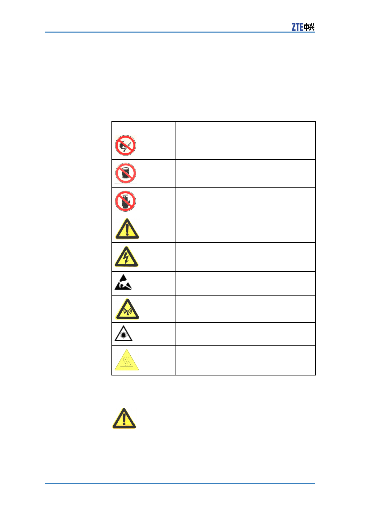
SafetySymbols
Table1listssafetysymbols.Theyaretoprompttheuserofthe
safetyprecautionstobeobservedduringZXSDRR8860operation
andmaintenance.
TABLE1SAFETYSYMBOLSDESCRIPTION
SafetySymbols
Meaning
Nosmoking:Smokingisforbidden
Noflammables:Noflammablescanbestored.
Notouching:Donottouch.
Universalalertingsymbol:Generalsafety
attentions.
Electricshock:Riskofelectricshock.
Electrostatic:Thedevicemaybesensitiveto
staticelectricity.
Microwave:Bewareofstrongelectromagnetic
field.
Laser:Bewareofstronglaserbeam.
Scald:Bewareofscald.
Amongstthesesafetysymbols,theuniversalalarmsymbolsare
classiedintothreelevels:danger ,warning,andcaution.The
formatsandmeaningsofthethreelevelsaredescribedasbelow:
Danger:
Indicatesapotentiallyhazardoussituationwhich,ifnotavoided,
willresultindeathorseriousinjuryofpeople,orequipmentdamagesandbreakdown.
2ConfidentialandProprietaryInformationofZTECORPORATION
Page 11
Chapter1SafteyDescription
Warning:
Indicatesapotentiallyhazardoussituationwhich,ifnotavoided,
couldresultindeathorseriousinjury.
Caution:
Indicatesapotentiallyhazardoussituationwhich,ifnotavoided,
couldresultinseriousinjuries,equipmentdamagesorinterruption
ofpartservices.
SafetyInstructions
ElectricalSafety
Thissectiondescribesthesafetyinstructionsrelatedtoelectrical
safety,antistatic,heavyobjectsandboards.
Thefollowingaretheelectricalsafetyinstructionsabouttools,high
Instructions
voltage,powercables,holesandlightning:
�Tools
Usespecialtoolsratherthancommontoolsforhigh-voltage
andACoperations.
�HighVoltage
Danger:
Highvoltageishazardous.Directorindirectcontactwithhigh
voltageormainsupplyusingawetobjectcouldresultindeath.
�StrictlyfollowlocalsafetyrulestoinstallACpowerequip-
ments.
�Installationstaffmustbequaliedforperforminghigh-volt-
ageandACoperations.
�Donotwearanywatch,handchain,bracelet,ringorany
otherconductiveobjectduringsuchoperations.
�Preventmoisturefromaccumulatingontheequipmentdur-
ingoperationsinadampenvironment.
�PowerCable
ConfidentialandProprietaryInformationofZTECORPORATION3
Page 12
ZXSDRR8860InstallationManual
Neverinstalloruninstallpowercableswhiletheyarelive.Otherwise,thepowercable,whencontactingaconductor ,mayresultinsparksorelectricarccausingareorevendamageto
eyes.
�Makesuretoshutoffpowersupplybeforeinstallingordis-
�Beforeconnectingthepowercable,makesurethatthecon-
�DrillingHoles
Itisnotallowedtodrillcabinetholeswithoutpermission.
Warning:
connectingapowercable.
nectingcableanditslabelisappropriatefortheactualinstallationrequirements.
Warning:
AntistaticSafety
�Unqualieddrillingcoulddamagewiringandcablesinside
thecabinet.Additionally,metalpiecesinsidethecabinetcreatedbythedrillingcouldresultinashortedcircuit
board.Useinsulationprotectionglovesandmovecables
withinthecabinetawayrstwhendrillingisnecessaryon
acabinet.
�Protecteyesduringdrillingasdustoryingdebrismay
damageeyes.
�Cleananydebrisintimeafterdrilling.
�Lightning
Danger:
Donotperformhigh-voltage,AC,irontowerormastoperations
inathunderstorm.
Thunderstormswouldgiverisetoastrongelectromagnetic
eldintheatmosphere.Therefore,theequipmentmustbe
groundedandprotectedintimeagainstlightningstrikes.
Instructions
Electrostatic:
Staticelectricityproducedbyhumanbodycandamagestatic-sensitivecomponentsoncircuitboard,suchaslarge-scaleintegrated
circuits.
�Frictioncausedbyhumanbodyactivitiesistherootcauseof
electrostaticchargeaccumulation.Staticvoltagecarriedbya
humanbodyinadryenvironmentcanbeupto30kV ,and
canremaininthereforalongtime.Anoperatorwithstatic
4ConfidentialandProprietaryInformationofZTECORPORATION
Page 13

HoistingHeavy
Chapter1SafteyDescription
electricitymaydischargeelectricitythroughacomponentwhen
he/shetouchestheconductorandcausingdamage.
�Wearanantistaticwriststrap(theotherendofwriststrapmust
bewellgrounded)beforetouchingtheequipmentorholding
aplug-inboard,circuitboard,IntegratedCircuit(IC)chipor
otherdevices,topreventhumanstaticelectricityfromdamagingsensitivecomponents.
�Aresistorover1MΩshouldbeconnectedinseriesonthecable
betweentheantistaticwriststrapandthegroundingpoint,to
protecttheoperatoragainstaccidentalelectricshock.Resistanceover1MΩislowenoughtodischargestaticvoltage.
�Theantistaticwriststrapusedmustbesubjecttoregular
check.Donotreplacethecableofanantistaticwriststrap
withanyothercable.
�Donotcontactstatic-sensitiveboardswithanyobjectthateas-
ilygeneratesstaticelectricity.Forexample,frictionofpackage
bag,transferboxandtransferbeltmadefrominsulationplasticmaycausestaticelectricityoncomponents.Dischargeof
staticelectricitymaydamagecomponentswhentheycontact
ahumanbodyortheground.
�Boardshouldonlycontactmaterialssuchasantistaticbag.
Keepboardsinantistaticbagsduringstorageandtransportation.
�Dischargestaticelectricityofthetestdevicebeforeuse,that
is,groundthetestdevicerst.
�DonotplacetheboardnearastrongDCmagneticeld,such
asthecathode-raytubeofamonitor .Keeptheboardatleast
10cmaway.
Objects
Warning:
Whenhoistingheavyobjects,ensurethatnobodyisstandingor
walkingunderthehoistedobject.
�Ensurethehoistercanmeethoistingrequirementswhendis-
assemblingheavyequipment,ormovingandreplacingequipment.
�Theoperatormustbedulytrainedandqualiedforhoisting
operations.
�Hoistingtoolsmustbeinspectedandcompletebeforeservice.
�Makesurethathoistingtoolsarexedrmlyonasufciently
securedobjectorwallbeforethehoistingoperation.
�Givebrieforalinstructionsduringhoistingoperationstopre-
ventanymishap.
Unplugging/Plug-
gingaBoard
�Neverplugaboardwithexcessiveforce,toensurethatthe
pinsonthebackplanedonotgetdeformed.
�Plugtheboardrightintotheslotandmakesureboardcircuit
facesdonotcontacteachotherlestanyshortcircuitmayoccur .
�Keephandsofftheboardcircuit,components,connectorsand
cabletroughwhenholdingaboard.
ConfidentialandProprietaryInformationofZTECORPORATION5
Page 14

ZXSDRR8860InstallationManual
OtherSafety
Instructions
Donotperformmaintenanceordebuggingindependently,unless
aqualiedpersonispresent.
�Replacinganypartsormakinganychangestotheequipment
mightresultinanunexpecteddanger .Therefore,besurenot
toreplaceanypartsorperformanychangestotheequipment
unlessauthorizedotherwise.
�ContactZTEofceifyouhaveanyquestion,toensureyour
safety.
Note:
6ConfidentialandProprietaryInformationofZTECORPORATION
Page 15

Chapter2
InstallationOverview
TableofContents:
ComponentstobeInstalled.................................................7
InstallationFlow.................................................................7
InstallationPreparation.......................................................8
ComponentstobeInstalled
ForZXSDRR8860,thefollowingcomponentswillbeinstalled:
�ZXSDRR8860cabinetandcomponents
Note:
Theinnercablesandfunctionalmodules/boardsinthecabinet
arealreadyinstalledbeforeequipmentdelivery.
�Sunshield(usedfortheoutdoorZXSDRR8860installation)
�Cables
�Antennafeedersystemincludingantenna,jumpersandfeeder
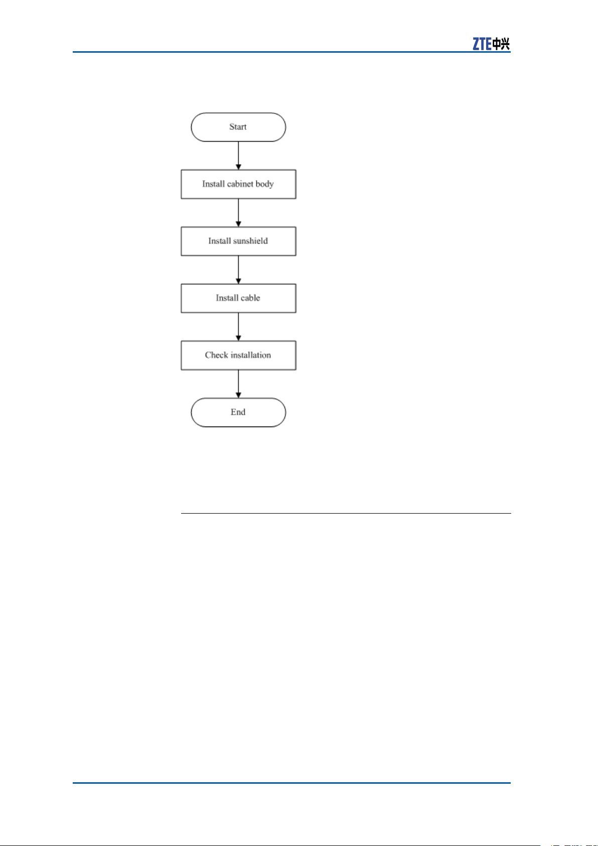
InstallationFlow
TheinstallationowofZXSDRR8860isdemonstratedinFigure1
.However ,itisnotrequiredtostrictlyfollowthestepsshowedin
thisow.Theactualinstallationproceduresdependontheonsite
requirements.
ConfidentialandProprietaryInformationofZTECORPORATION7
Page 16
ZXSDRR8860InstallationManual
FIGURE1INSTALLATIONFLOW
InstallationPreparation
EngineeringConditionInspection
Beforeinstallingdevices,followtherequirementsofEnvironment
AcceptanceReportandcheckinstallationenvironment.Thefol-
lowingcontentisjustasareference.
Installation
Position
Inspection
Temperature
andHumidity
Inspection
ZXSDRR8860installationpositionshouldaccordwiththerequirementsofengineeringdesign,thespeciedrequirementsasfollows:
�Avoiddusty,harmful-gasorexplosive-goodsenvironment;
�Avoidtheplaceswithbigshockorstrongnoise;
�Farawaysubstation;
�Farawaypollutionsource;
�Avoidanindustrialboilerandheatingboiler;
�Farawayhigh-powerwirelessinterferencesource.
ZXSDRR8860temperatureandhumidityinworkenvironment
shouldmeettherequirements,asshownin
8ConfidentialandProprietaryInformationofZTECORPORATION
Page 17

Chapter2InstallationOverview
PowerSupply
Inspection
TherequirementsofZXSDRR8860powersupplyaredescribedas
follows.
1.DCpowersupply:ZXSDRR8860is–48VDCpowersupplyand
thevoltageofpowersupplyis–40VDC~–57VDC.
2.IndirectACpowersupply:adoptanoutdoorACunit(OAU);
theOAUcanprovide220VACpowersupplyforoneZXSDR
B8200C100andoneZXSDRR8860atthesametime.
Lightning
Inspection
TheZXSDRR8860lightningrequirementsaredescribedasfollows.
�OutdoorInstallation
i.ForDCpowersupply,congureanoutdoorDClightningbox
OLP48-2.IftheDCpowerisexportedfromtheequipment
room,thelengthofpowercableismorethan10m(less
than50m)andtheoutputendofindoorDCpowerisnot
conguredwithB-levelorabovelightningdevices,itisrequiredtocongureanindoorDClightningboxILP48–3in
theequipmentroom.
ii.ForindirectACpowersupply,itisrequiredtocongurean
AClightningbox(ZXPCScombinedarrester).
�Forindoorinstallation,ifthepowercableisdistributedout-
doors,congurethepowerlightningboxaccordingtotheconditionsofoutdoorinstallation.
Grounding
Inspection
OtherInspections1.Thecorollarydevicesorcomponentsshouldaccordwiththe
ZXSDRR8860adoptsanassociatedgroundingmode.Thevalue
ofgroundingresistanceisnotmorethan5ohm.
requirementsofZXSDRR8860engineeringdesigndrawing.
2.ThetransmissiondevicesinterconnectedwithBBUshouldhave
beenprepared.
ToolsandInstrumentsPreparation
Table2showstoolsandmeterslistrequiredduringinstallation.
TABLE2TOOLANDMETERLIST
Category
Special-purposetools
Concretedrillingtools
Name
Onefeederconnectorknife
Onewirestripper
Onecrimpingpliers
Onemulti-functionalcrimpingpliersEarth
resistancetester
Oneelectricpercussiondrill
Auxiliaryandsamplebits
Onevacuumcleaner
Powersocket(two-phaseandthree-phase
socket,withcurrentcapacitygreaterthan15
A)
ConfidentialandProprietaryInformationofZTECORPORATION9
Page 18

ZXSDRR8860InstallationManual
Category
General-purposetools
Measurementtools
Protectiontools
Clamptools
Auxiliarytools
Name
Crossscrewdrivers(4”,6”and8”each)
Flatheadscrewdrivers(4” ,6”and8”each)
Adjustablewrenches(6’ ,8’ ,10’and12’)
Dual-purposespanners(17”and19”each)
Onesetofsocketwrench
5kg(11lb)nailhammer
One300Wiron
One40Wiron
Solderwires
Hotblower
Oilpaintbrush
Pliers
Scissor
Paperknife
One50m(164feet)tapemeasure
One5m(16feet)steeltape
One400mm(16inches)levelbar
Oneanglemeter
Onecompass
Plumb
Antistaticwriststrap
Safetyhelmet
Pairofgloves
Onehacksaw(withseveralsawblades)
Onepairofsharp-nosepliers(8″)
Onepairofdiagonalpliers(8″)
Onepairofslipjointpliers(8″)
Onepairofvices(8″)
Crowbar
Chainwheel
Rope
Ladder
Forklift
On-siteDocuments
ZXSDRR8860installationneedsthefollowingtechnicaldocuments
tobeready.
10ConfidentialandProprietaryInformationofZTECORPORATION
Page 19

Chapter2InstallationOverview
�ZXSDRR8860EngineeringExplorationReport
�ZXSDRR8860EnvironmentAcceptanceReport
ZXSDRR8860manualkitincludes:
�ZXSDRR8860CommissioningandCongurationManual
�ZXSDRR8860OperationandMaintenanceManual
�ZXSDRR8860TechnicalManual
UnpackingAcceptance
CountingGoods
PrerequisiteThetransportedcargoshouldhavereachedtheinstallationsite.
ContextTherepresentativeofcustomerandtheprojectsupervisormustbe
presentonsiteduringcountingofgoodsreceived.Ifanypartyis
notpresentatthattime,transportermustholdtheresponsibility
foranydiscrepanciesingoods.
Thestepsinvolvedincountinggoodsareasfollows:
Steps1.CheckDeliveryChecklistofZTECorporation.Checktotalnum-
berofgoods,intactnessofpackingboxes,andcheckwhether
arrivalplaceistheactualinstallationplaceagainstpackinglist
numberattachedtopackingboxes.Ifgoodsareintact,start
tounpackandinspectthem.
Note:
Itisrecommendedtounpackthegoodsafterabout30minutes
ofreceivingthecargo,sincethereisapossibilityofmoisture
contentduetotemperaturevariationsifany .
2.Equipmentinspectionlistandunpackingacceptancereportare
presentintherstpackingcarton.Firstly,openrstpacking
cartonandtakeouttheUnpackingAcceptanceReporttocheck
whetherthegoodsreceivedareinaccordancewiththeinspectionlist.
3.Duringthecountingandunpackinginspectionprocess,ifany
materialisfoundshort,orgoodsdamaged,thenll-inUnpack-
ingAcceptanceFeedbackTableandcontactZTEpromptly.
ENDOFSTEPS.
CrateUnpacking
PrerequisitePreparetheappropriatetoolssuchasstraightscrewdriver ,pliers,
andcrowbar .
ContextPerformthefollowingstepstoopenthecrate:
ConfidentialandProprietaryInformationofZTECORPORATION11
Page 20

ZXSDRR8860InstallationManual
Steps1.Insertastraightscrewdriverintotheslitbetweencrateand
frontcoverboardtomakeitloose;theninsertcrowbartounclenchcoverboard.
2.Pullthecoverboardoutfromthecrate.
3.Removetheotherboardsofthecrate.
ENDOFSTEPS.
CartonUnpacking
PrerequisitePreparetheappropriatetoolssuchasstraightscrewdriver ,diago-
nalpliers,andpaperknife.
ContextPerformthefollowingstepstounpackthecarton:
Steps1.Usediagonalplierstocutpackingstraps.
2.Useapaperknifetocutadhesivetapealongtheslitsoncarton
cover ,avoiddamaginggoodsinside.
3.Openthecarton,andremovethefoamboard.
4.Checkthegoodswithinthecarton.
Note:
�Avoiddamagingtheantistaticbag(Itcanbeusedinthe
futureforstorageofspareparts)duringunpacking.
�Whiletheequipmentismovedtoahotteranddamper
place,waitfor30minutesbeforeunpackingtheequipment.
Otherwise,moisturemaycondenseonthesurfaceofthe
equipmentandcausedamage.
�Properlydisposeofrecycledesiccants.
ENDOFSTEPS.
AcceptanceandGoodsHandover
ContextPerformthisprocedureforacceptinggoods,andhandingthem
overtooperators.
Steps1.Acceptance
Baseduponthename,categoryandnumbermentionedonthe
shippinglist,carefullycheckthegoodspiecebypiece.Make
surethatgoodsfullthefollowingconditions:
i.Makesurethattherearenobubbly ,peeling,nickandlth
markonthesurfaceofthechassis.
ii.Ensurethatoilpaintonthechassissurfaceisintact.
iii.Ensureclampingscrewsaretightandintact.
iv.Allthecomponentsareproperlyinstalledattheirrespective
positions.
12ConfidentialandProprietaryInformationofZTECORPORATION
Page 21

Chapter2InstallationOverview
v.Laydowntheinspectedgoodsaccordingtocategories.
2.Handover
Aftercompletingtheunpackingprocedure,representativeof
customerandprojectsupervisorshouldapproveandsignUn-
packingforInspectionReport.Eachpartyshouldhaveacopy
ofUnpackingforInspectionReport.Ifthegoodsarestillunderthesupervisionoftheoperatorevenafteracceptance,then
goodswillnotbehandedovertotheoperatoruntilbothparties
signonthereport.
ENDOFSTEPS.
ConfidentialandProprietaryInformationofZTECORPORATION13
Page 22

ZXSDRR8860InstallationManual
Thispageisintentionallyblank.
14ConfidentialandProprietaryInformationofZTECORPORATION
Page 23

Chapter3
CabinetInstallation
TableofContents:
EngineeringIndices...........................................................15
InstallationModeInstruction...............................................16
Pole-mountedInstallationMode...........................................17
Wall-mountedInstallationMode...........................................33
FloorGantry-mountedInstallationMode...............................37
SimpliedCabinetIntegratedInstallationMode.....................54
InstallingSunshield..........................................................65
EngineeringIndices
Table3describestheengineeringindicesofZXSDRR8860.
TABLE3ZXSDRR8860ENGINEERINGINDICES
Item
OverallDimensionWidthxHeightxDepth:320mmx500mm
UpperEnclosure
Dimension
LowerEnclosure
Dimension
Weight<22kg
Power
WorkTemperature
WorkHumidity
PowerConsumptionof
NormalWorkUnder-48V
DCPowerSupply
x172mm
WidthxHeightxDepth:320mmx370mm
x72mm
WidthxHeightxDepth:320mmx500mm
x100mm
-48VDC;-40V~-57V
220VAC:150V~285V/45Hz~65
Hz(viaexternalAC-to-DCconversion
lightningbox)
-40℃to55℃-40℉to131℉
5%RH~95%RH
�1Carrier
–OutputPower:20W/C/S
–PowerConsumption:170W
�2Carrier
–OutputPower:20W/C/S
–PowerConsumption:200W
�3Carrier
–OutputPower:20W/C/S
–PowerConsumption:230W
Indices
ConfidentialandProprietaryInformationofZTECORPORATION15
Page 24

ZXSDRR8860InstallationManual
ThetechnicalindicesoftheindoorDClightningbox,exemplied
byJD40K085C20H2–K1Z,arelistedinT able4,whichissubjectto
theactualeldtechnicalspecicationsforpracticalapplication.
TABLE4JD40K085C20H2–K1ZDCLIGHTNINGBOXTECHNICALINDICES
Item
Dimensions
NominalWorking
Voltage
InstallationModeIndoorwall-mountinstallation
WorkingTemperature
WorkingHumidity
WidthxHeightxDepth:400mmx450
mmx100mm(Theheightoftopcoverbox
lockexcluded)
–48V
-5℃to70℃
≤95%RH
Index
ThetechnicalindicesoftheexternalAC-to-DCconversionlightning
box,exempliedbyGPAD501M54-1A,arelistedinT able5,which
issubjecttotheactualeldtechnicalspecicationsforpractical
application.
TABLE5GPAD501M54-1AEXTERNALAC-TO-DCCONVERSIONLIGHTNING
BOXTECHNICALINDICES
Item
Dimensions
Weight4.65kg
InputVoltageMin.value:150V
InputFrequency
InstallationModePole-mountandwall-mountinstallation
WorkingTemperature
WorkingHumidity
WidthxHeightxDepth:217mmx288
mmx127mm
Typicalvalue:220V
Max.value:285V
Min.value:45Hz
Typicalvalue:50Hz
Max.value:65Hz
-40℃+65℃
5%95%
Index
InstallationModeInstruction
Accordingtodifferentinstallationenvironments,therearethree
modesofZXSDRR8860installation:
�Pole-mountinstallation
�Wall-mountinstallation
�Gantry-mountinstallation
�Simplied-cabinetintegrativeInstallation
16ConfidentialandProprietaryInformationofZTECORPORATION
Page 25

Chapter3CabinetInstallation
Pole-mountedInstallation Mode
ComponentsUsedinPole-mount Installation
Themaincomponentsusedinpole-mountinstallationinclude:
�Poleanchorclampcomponents;
�Polexingbracketcomponents.
Thepoleanchorclampcomponentsareusedforpole-mountinstallationofoneortwoZXSDRR8860s.Thepolexingbracket
componentsareusedforpole-mountinstallationofthreeZXSDR
R8860s.
Themainpoleanchorclampcomponentsusedinpole-mountinstallationforsingleZXSDRR8860arelistedinT
able6
TABLE6MAINCOMPONENTLIST1
Name
Shortanchorclamp
Longanchorclamp
Standardspringwasher10
M10×120hexagonheadbolt(full
thread)
I-typecommonM10hexagonal
nut
Flatwasher10
Standardspringwasher8
M8×40hexagonheadbolt
Bigwasher8
Themainpoleanchorclampcomponentsusedinpole-mountinstallationfortwoZXSDRR8860arelistedinT
TABLE7MAINCOMPONENTLIST2
Name
Quantity
2
2
4
4
4
4
4
4
4
able7
Quantity
Longanchorclamp
Standardspringwasher10
M10×120hexagonheadbolt(full
thread)
M10×80hexagonheadbolt(full
thread)
ConfidentialandProprietaryInformationofZTECORPORATION17
4
4
4
4
Page 26
ZXSDRR8860InstallationManual
Name
I-typecommonM10hexagonal
nut
Flatwasher10
Standardspringwasher8
M8×40Hexagonheadbolt
Bigwasher8
Quantity
4
4
8
8
8
Themainpolexingbracketcomponentsusedinpole-mountinstallationforthreeZXSDRR8860arelistedinTable8
TABLE8MAINCOMPONENTLIST3
Name
Polefixingbracket
Standardspringwasher10
M10×120hexagonheadbolt(full
thread)
I-typecommonM10hexagonal
nut
Flatwasher10
Standardspringwasher8
M8×40hexagonheadbolt
Bigwasher8
Quantity
4
4
4
4
4
12
12
12
Figure2illustratespoleanchorclampcomponents.Figure3illus-
tratespolexingbracketcomponents.
FIGURE2POLEANCHORCLAMPCOMPONENTS
18ConfidentialandProprietaryInformationofZTECORPORATION
Page 27
Chapter3CabinetInstallation
FIGURE3POLEFIXINGBRACKETCOMPONENTS
Note:
ThepoleanchorclampcomponentsshowninFigure2isadoptedin
onepole-mountinstallation.Thepoleanchorclampcomponents
usedintwopole-mountinstallationonlychangestwoshortanchor
clampsintotwolonganchorclamps,thespeciclistdescribedin
Table7
InstallingTwoZXSDRR8860C806
Pole-mountCabinets(WithoutWave
Trap)
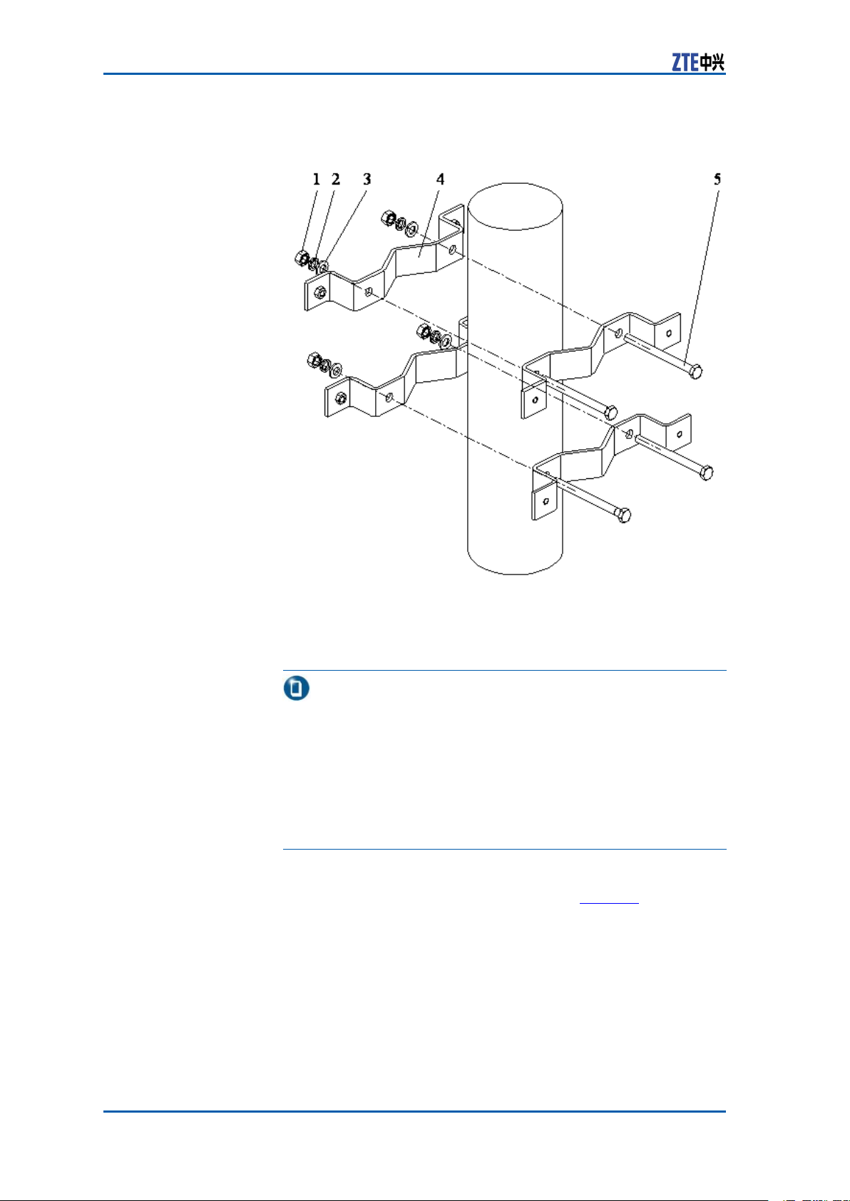
Steps1.Fixanchorclampsbacktobackontothepole,andalignthe
holesandscrewdownabitwithbolts.Adjustspacebetween
anchorclampsbasedonthescrews’positionofsupporting
panelasshowninFigure4.
ConfidentialandProprietaryInformationofZTECORPORATION19
Page 28
ZXSDRR8860InstallationManual
FIGURE4POLE-MOUNTINSTALLATION(1)
1.I-typecommonM10hexago-
nalnut
2.Standardspringwasher10
3.Bigatwasher10
4.Longanchorclamp
5.M10×120hexagonheadbolt
(fullthread)
Tip:
DuringtwoZXSDRR8860cabinetinstallation,thesuggested
polediameteris60to120mmandtherearetwokindsofbolt
lengths:
�Usetheboltoflength80mmforpolediameterof60mm
to90mm;
�Usetheboltoflength120mmforpolediameterof90mm
to120mm.
2.FixtwosupportingpanelsontheanchorclampwithM8bolts
andscrewM10boltstightly ,asshowninF
igure5.
20ConfidentialandProprietaryInformationofZTECORPORATION
Page 29

FIGURE5POLE-MOUNTINSTALLATION(2)
Chapter3CabinetInstallation
1.M8×40Hexagonheadbolt
2.Standardspringwasher8
3.Bigatwasher8
4.Insulationange
5.Supportingpanel
6.Insulationboard
7.Longanchorclamp
3.MountthetwoZXSDRR8860cabinetsonthesupportingpanel
andfastenthecabinetwithfourM6X20hexagonsocketcap
screwsasshowninF
FIGURE6POLE-MOUNTINSTALLATION(3)
igure6.
ConfidentialandProprietaryInformationofZTECORPORATION21
Page 30
ZXSDRR8860InstallationManual
ENDOFSTEPS.
InstallingTwoZXSDRR8860C806
Pole-mountCabinets(WithWave
Trap)
ContextWhileinstallingtheZXSDRR8860C806pole-mountinstallation
withtwowavetraps,adoptanchorclamps;forthepole-mount
installationofthreewavetraps,adoptxingbrackets.
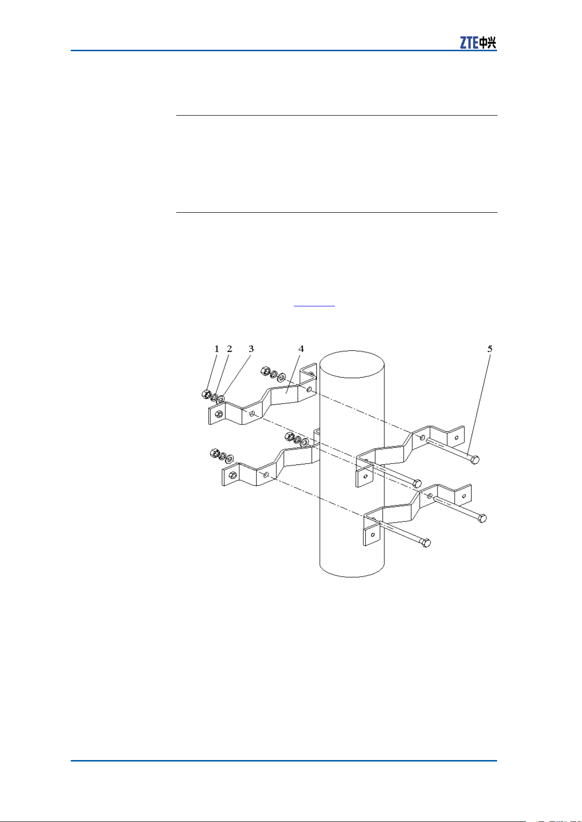
Steps1.Fixanchorclampsbacktobackontothepole,aligntheholes
andscrewdownabitwithbolts.Adjustspacebetweenanchor
clampsasshowninF
FIGURE7POLE-MOUNTINSTALLATION(1)
igure7.
1.I-typecommonM10hexagonalnut
2.Standardspringwasher10
3.Flatwasher10
4.Longanchorclamp
5.M10×120hexagonheadbolt
(fullthread)
22ConfidentialandProprietaryInformationofZTECORPORATION
Page 31

Chapter3CabinetInstallation
Tip:
DuringtwoZXSDRR8860installation,thesuggestedpolediameteris60to120mmandtherearetwokindsofboltlengths:
�Usetheboltoflength80mmforpolediameterof60mm
to90mm.
�Usetheboltoflength120mmforpolediameterof90mm
to120mm.
2.FixtwosupportingpanelsontheanchorclampswithM8bolts
andscrewdownM10bolts,asshowninFigure8.
FIGURE8POLE-MOUNTINSTALLATION(2)
1.M8×40hexagonheadbolt
2.Standardspringwasher8
3.Bigatwasher8
4.Insulationange
5.Supportingpanel
6.Insulationboard
7.Longanchorclamp
3.RepeattheStep1~Step2toinstalltwoanchorclampsandtwo
supportingpanels.
4.MountthetwoZXSDRR8860cabinetsontothesupportingpanelsandfastenthecabinetwithfourM6X20hexagonsocketcap
screwsasshowninF
ConfidentialandProprietaryInformationofZTECORPORATION23
igure9.
Page 32

ZXSDRR8860InstallationManual
FIGURE9POLE-MOUNTINSTALLATION(3)
5.MountthetwowavetrapsontothesupportingpanelsandfastenthemtothesupportingpanelswithfourM6X20hexagon
socketcapscrewsasshowninFigure10.
FIGURE10WAVETRAPINSTALLATION
1.Wavetrap
2.Fixingbeam
24ConfidentialandProprietaryInformationofZTECORPORATION
3.Supportingpanel
Page 33

Chapter3CabinetInstallation
ENDOFSTEPS.
InstallingThreeZXSDRR8860C806
CabinetsonPole(WithoutWave
Trap)
Steps1.Fixthetwosetsofxingbracketsontothepoleandalignthe
holesandscrewitabitwithbolts,asshowninF
FIGURE11POLE-MOUNTINSTALLATION(1)
igure11
1.FixingBracket
2.M10×120hexagonheadbolt
(fullthread)
3.Standardspringwasher10
2.Adjustspacebetweenthexingbracketsbasedonthescrews’
positionofinsulationboardsatthebackofsupportingpanels
asshowninFigure12.Fixthreesupportingpanelsonthe
xingbracketswithM8bolts.Screwthexingbracketswith
M10bolts.
ConfidentialandProprietaryInformationofZTECORPORATION25
4.Flatwasher10
5.I-typecommonM10hexagonalnut
Page 34

ZXSDRR8860InstallationManual
FIGURE12POLE-MOUNTINSTALLATION(2)
1.Fixingbracket
2.Insulationboard
3.Supportingpanel
4.Insulationange
5.Bigatwasher8
6.Standardspringwasher8
7.M8×40Hexagonheadbolt
3.MounttheZXSDRR8860cabinetsonthesupportingpanelsand
fastenthecabinetswithM6X20hexagonsocketcapscrewsas
showninF
FIGURE13POLE-MOUNTINSTALLATION(3)
igure13.
26ConfidentialandProprietaryInformationofZTECORPORATION
Page 35

Chapter3CabinetInstallation
Tip:
Thesidewithoutxingbracketcanbelocatedalongthewall.
ENDOFSTEPS.
InstallingThreeZXSDRR8860C806
CabinetonPole(WithWaveTrap)
ContextWhileinstallingtheZXSDRR8860C806pole-mountinstallation
withtwowavetraps,adoptanchorclamps;forthepole-mount
installationofthreewavetraps,adoptxingbrackets.
Steps1.Fixthetwosetsofxingbracketsontothepoleandalignthe
holesandscrewitabitwithbolts,asshowninFigure14.
FIGURE14POLE-MOUNTINSTALLATION(1)
1.FixingBracket
2.M10×120hexagonheadbolt
(fullthread)
3.Standardspringwasher10
4.Flatwasher10
5.I-typecommonM10hexagonalnut
2.Adjustspacebetweenthexingbracketsbasedonthescrews’
positionofinsulationboardsatthebackofsupportingpanels
asshowninF
igure15.Fixthreesupportingpanelsonthexing
bracketswithM8bolts.Screwdownthexingbracketswith
M10bolts.
ConfidentialandProprietaryInformationofZTECORPORATION27
Page 36

ZXSDRR8860InstallationManual
FIGURE15POLE-MOUNTINSTALLATION(2)
1.Fixingbracket
2.Insulationboard
3.Supportingpanel
4.Insulationange
5.Bigatwasher8
6.Standardspringwasher8
7.M8×40Hexagonheadbolt
3.RepeattheStep1~Step2toinstalltwosetsofxingbrackets
andthreesetsofsupportingpanels,asshowninF
igure16.
28ConfidentialandProprietaryInformationofZTECORPORATION
Page 37

FIGURE16POLE-MOUNTINSTALLATION(3)
Chapter3CabinetInstallation
1.Supportingpanel
4.MounttheZXSDRR8860cabinetsonthesupportingpanelsand
fastenthecabinetswithM6X20hexagonsocketcapscrewsas
showninFigure17.
ConfidentialandProprietaryInformationofZTECORPORATION29
Page 38
ZXSDRR8860InstallationManual
FIGURE17POLE-MOUNTINSTALLATION(4)
Tip:
Thesidewithoutxingbracketcanbelocatedalongthewall.
5.Mountthewavetrapsontothesupportingpanelandfastenit
tothesupportingpanelwithfourM6X20hexagonsocketcap
screws,asshowninF
igure18.
30ConfidentialandProprietaryInformationofZTECORPORATION
Page 39

FIGURE18WAVETRAPINSTALLATION
Chapter3CabinetInstallation
1.Wavetrap
2.Fixingbeam
3.Supportingpanel
ENDOFSTEPS.
ExampleAfterinstallationcompleted,theappearanceisasshowninFigure
19.
ConfidentialandProprietaryInformationofZTECORPORATION31
Page 40

ZXSDRR8860InstallationManual
FIGURE19INSTALLATIONCOMPLETION
1.Pole
2.ZXSDRR8860
3.Wavetrap
4.LightningBox
32ConfidentialandProprietaryInformationofZTECORPORATION
Page 41

Chapter3CabinetInstallation
Note:
InFigure19,anoutdoorDClightningboxoranAClightningbox
canbeadoptable.Theapplicationandinstallationforbothrefer
toAppendixCandAppendixE.
Wall-mountedInstallation Mode
ComponentsUsedinWall-Mount Installation
Thecomponentsusedinwall-mountinstallationarelistedinTable
9
TABLE9MAINCOMPONENTS
Name
Supportingpanel
Drilltemplate
M8×80expansionbolt
Bigwasher8
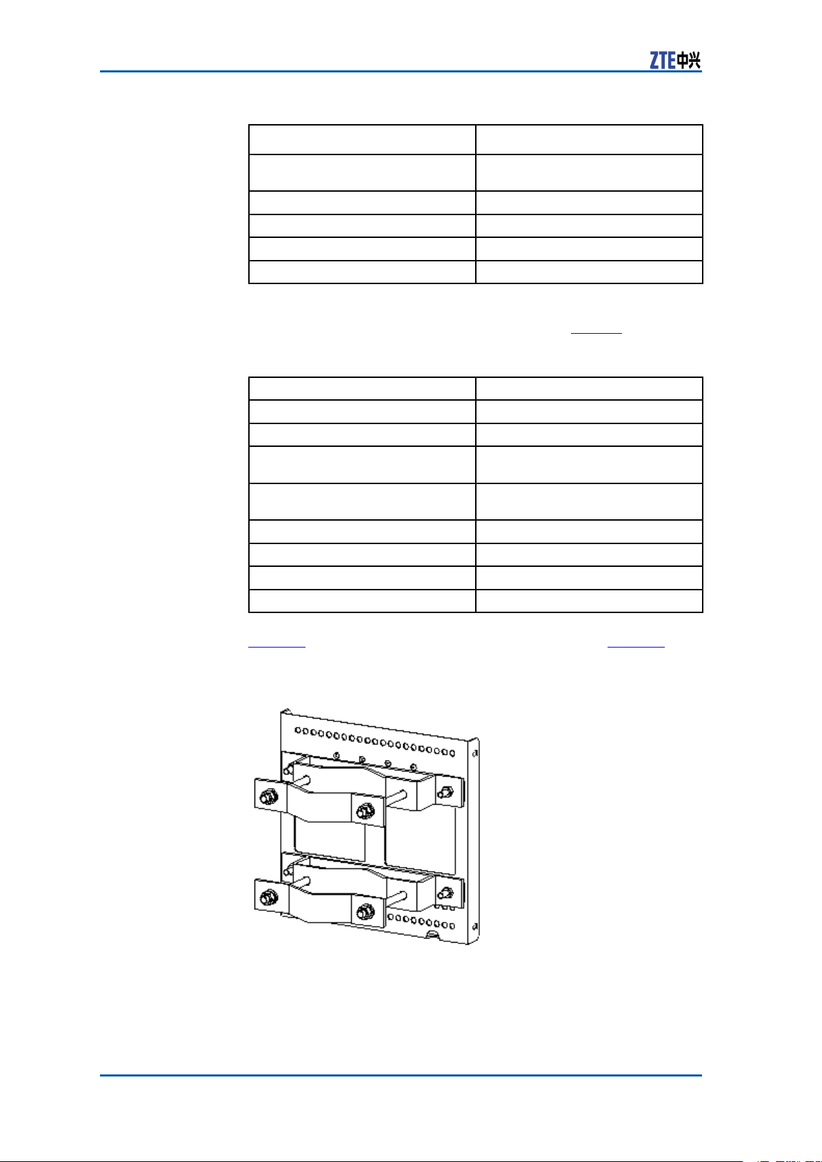
ThesupportingpanelisshowninFigure20.Theholemarking
designtemplateisshowninFigure21.
FIGURE20SUPPORTINGPANEL
Quantity
1
1
4
4
ConfidentialandProprietaryInformationofZTECORPORATION33
Page 42

ZXSDRR8860InstallationManual
Thesupportingpanel,asthecommoncomponentinZXSDRR8860
installation,isusedinthewall-mount,pole-mountandgantrymountinstallationmodes.
FIGURE21HOLEMARKINGDESIGNTEMPLATE(UNIT:MM)
Note:
InstallingCabinetonWall (Wall-Mount)
ContextFigure22illustratesthespacerequirement(Unit:mm)forwall-
mountinstallation.
34ConfidentialandProprietaryInformationofZTECORPORATION
Page 43

Chapter3CabinetInstallation
FIGURE22SPACEREQUIREMENTFORWALL-MOUNTINSTALLATION(UNIT:
MM)
Steps1.Firstlymarktheholepositionsonthewallwithholedesign
template.Drillthemarkedpointsabout60mmwithpercussive
drillandinstalltheexpansionbolts.
2.Fixthesupportingpanelonthewallwithboltsasshownin
F
igure23
ConfidentialandProprietaryInformationofZTECORPORATION35
Page 44

ZXSDRR8860InstallationManual
FIGURE23SUPPORTINGPANELINSTALLATIONONWALL
1.M8×80expansionbolt
2.Insulationboard
3.Supportingpanel
4.Insulationange
5.Bigatwasher8
6.Standardspringmat8
7.M8nut
l
3.MounttheZXSDRR8860cabinetontothesupportingpanel,
andfastenthecabinetwithfourM6X20hexagonsocketcap
screwsasshowninF
igure24.
36ConfidentialandProprietaryInformationofZTECORPORATION
Page 45

FIGURE24MOUNTINGCABINET
Chapter3CabinetInstallation
1.Supportingpanel
2.M6safeguardscrew
ENDOFSTEPS.
3.Retainingboard
FloorGantry-mounted InstallationMode
ComponentsUsedingantry-mount Installation
Thecomponentsusedingantry-mountinstallationincludesa
gantryandsupportingpanels.Thequantityofsupportingpanels
isconsistentwiththatofZXSDRR8860s.ForeveryZXSDRR8860
cabinet,onesupportingpanelisrequired.
ConfidentialandProprietaryInformationofZTECORPORATION37
Page 46

ZXSDRR8860InstallationManual
Table10listssomecomponentsofgantry.
TABLE10MAINCOMPONENTS
Name
Gantry
Quantity
1
M5X16screw24
M10X40tappingscrew6
M10X100expansionbolt
4
Figure25showstheappearanceofgantry.
38ConfidentialandProprietaryInformationofZTECORPORATION
Page 47

FIGURE25GANTRYAPPEARANCE
Chapter3CabinetInstallation
1.Coverplate
2.Uprightcolumn
3.Tiltedsupport
4.M5X16screw
5.Baseplate
6.M10X40tappingscrew
7.M10X100expansionbolt
ConfidentialandProprietaryInformationofZTECORPORATION39
Page 48

ZXSDRR8860InstallationManual
AdopttheM10X100expansionboltwhileinstallingthegantryon
aconcretebaseplate;adopttheM10X40tappingscrewwhileinstallingthegantryinsideabunker .
Table11listssomecomponentsofsupportingpanel.
TABLE11MAINCOMPONENTS
Note:
Name
Supportingpanel
M8×80expansionbolt
Bigwasher8
Quantity
1
4
4
Figure26showstheappearanceofsupportingpanel.
FIGURE26SUPPORTINGPANEL
40ConfidentialandProprietaryInformationofZTECORPORATION
Page 49
Note:
Thesupportingpanel,asthecommoncomponentinZXSDRR8860
installation,isusedinthewall-mount,pole-mountandgantrymountinstallationmodes.
InstallingCabinetonGantry(Without WaveTrap)
Steps1.Assemblethegantry
i.FixtheuprightcolumnuponthebaseplatewiththeM5X16
screws,asshowninFigure27.
FIGURE27FIXUPRIGHTCOLUMNANDBASEPLATE
Chapter3CabinetInstallation
1.M5X16screw
ii.Fastenthejunctionbetweenuprightcolumnandcoverplate
withtheM5X16screws,asshowninFigure28.
ConfidentialandProprietaryInformationofZTECORPORATION41
Page 50

ZXSDRR8860InstallationManual
iii.FastenthetiltedsupportwiththeM5X16screws,asshown
FIGURE28FASTENUPRIGHTCOLUMNANDCOVERPLATE
1.M5X16screw
inFigure29
FIGURE29FASTENTILTEDSUPPORT
1.M5X16screw
2.Installthegantry
Accordingtothespeciedinstallationpositionintheengineeringdesigndrawing,drillthemarkedholesandinstalltheexpansionbolts.
42ConfidentialandProprietaryInformationofZTECORPORATION
Page 51

Chapter3CabinetInstallation
Note:
AdopttheM10X100expansionboltwhileinstallingthegantry
onaconcretebaseplate;adopttheM10X40tappingscrew
whileinstallingthegantryinsideabunker .
3.InstalltheZXSDRR8860
i.Fastenthesupportingpanelsontotheproperpositionsof
gantrywithbolts.
ii.MounttheZXSDRR8860cabinetsontothesupporting
panels,andfastenthecabinetswithfourM6X20hexagon
socketcapscrews.
ENDOFSTEPS.
ExampleTheappearanceafterinstallationcompletionisasshowninFigure
30.
ConfidentialandProprietaryInformationofZTECORPORATION43
Page 52

ZXSDRR8860InstallationManual
FIGURE30ZXSDRR8860INDOORGANTRY-MOUNTINSTALLATION
APPEARANCE(ONLYRRUINSTALLED)
InstallingCabinetonGantry(With WaveTrap)
Steps1.Assemblethegantry.
44ConfidentialandProprietaryInformationofZTECORPORATION
Page 53

Chapter3CabinetInstallation
i.FixtheuprightcolumnuponthebaseplatewiththeM5X16
screws,asshowninFigure31.
FIGURE31FIXUPRIGHTCOLUMNANDBASEPLATE
1.M5X16screw
ii.Fastenthejunctionbetweenuprightcolumnandcoverplate
withtheM5X16screws,asshowninF
FIGURE32FASTENUPRIGHTCOLUMNANDCOVERPLATE
1.M5X16screw
igure32.
ConfidentialandProprietaryInformationofZTECORPORATION45
Page 54

ZXSDRR8860InstallationManual
iii.FastenthetiltedsupportwiththeM5X16screws,asshown
inFigure33.
FIGURE33FASTENTILTEDSUPPORT
1.M5X16screw
2.Installthegantry.
Accordingtothespeciedinstallationpositionintheengineeringdesigndrawing,drillthemarkedholesandinstalltheexpansionbolts.
Note:
AdopttheM10X100expansionboltwhileinstallingthegantry
onaconcretebaseplate;adopttheM10X40tappingscrew
whileinstallingthegantryinsideabunker .
3.Installthesupportingbracketofwavetrap.
ThesupportingbracketofwavetrapisasshowninFigure34.
FastenthesupportingbracketontothegantrywithM8bolts,
asshowninF
igure35.
46ConfidentialandProprietaryInformationofZTECORPORATION
Page 55

FIGURE34SUPPORTINGBRACKET
Chapter3CabinetInstallation
1.M8bolt
2.Insulationboard
3.Supportingbracket
4.InstalltheZXSDRR8860.
i.Fastenthesupportingpanelsontotheproperpositionsof
gantrywithbolts,asshowninFigure35.
ConfidentialandProprietaryInformationofZTECORPORATION47
Page 56

ZXSDRR8860InstallationManual
FIGURE35SUPPORTINGBRACKETANDWALL-MOUNTASSEMBLIES
1.Gantry
2.Supportingbracket
ii.MounttheZXSDRR8860cabinetsontothesupporting
panels,andfastenthecabinetswithfourM6X20hexagon
socketcapscrews,asshowninFigure36.
48ConfidentialandProprietaryInformationofZTECORPORATION
3.Supportingpanel
4.BBUwall-mountframe
Page 57
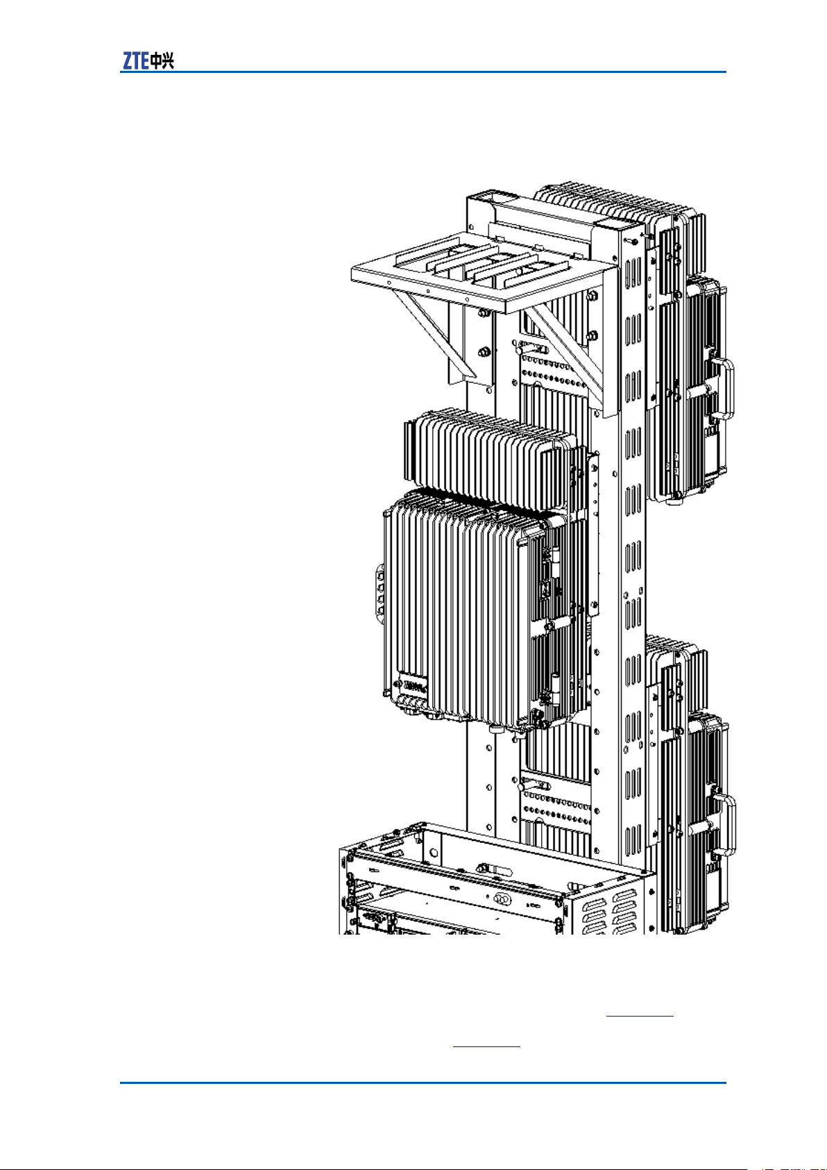
FIGURE36ZXSDRR8860INSTALLATION
Chapter3CabinetInstallation
5.Installthewavetrap.
TheappearanceofwavetrapisasshowninF
thewavetrapintothesupportingbracketandfastenthemwith
M6bolts,asshowninFigure38.
ConfidentialandProprietaryInformationofZTECORPORATION49
igure37.Insert
Page 58

ZXSDRR8860InstallationManual
FIGURE37WAVETRAP
1.Guideblock
2.Wavetrap
3.M6bolt
4.Frontbafer
50ConfidentialandProprietaryInformationofZTECORPORATION
Page 59

FIGURE38WAVETRAPINSTALLATION
Chapter3CabinetInstallation
ENDOFSTEPS.
ExampleTheZXSDRR8860gantry-mountintegratedinstallationiscom-
pleted.TheprolesareasshowninFigure39andFigure40.
ConfidentialandProprietaryInformationofZTECORPORATION51
Page 60

ZXSDRR8860InstallationManual
FIGURE39GANTRY-MOUNTINTEGRATEDINSTALLATION
1.ZXSDRR8860
2.ZXSDRB8200C100
3.Groundingcopperbar
4.Gantry
5.Wavetrap
52ConfidentialandProprietaryInformationofZTECORPORATION
Page 61

Chapter3CabinetInstallation
FIGURE40GANTRY-MOUNTINTEGRATEDINSTALLATION(SIDE)
ConfidentialandProprietaryInformationofZTECORPORATION53
Page 62

ZXSDRR8860InstallationManual
SimplifiedCabinetIntegrated InstallationMode
ComponentsUsedinIntegrated Installation
TheZXSDRR8860forintegratedinstallationneedsthefollowing
components:asimpliedcabinet,anupperxingframeanda
lowerxingframe.
Thedimensionofsimpliedcabinetis1650×600×450(H×W×D;
unit:mm),asshowninF
igure41.
54ConfidentialandProprietaryInformationofZTECORPORATION
Page 63

FIGURE41SIMPLIFIEDCABINETAPPEARANCE
Chapter3CabinetInstallation
1.M10×100expansionbolt
TheupperxingframeisasshowninFigure42.
ConfidentialandProprietaryInformationofZTECORPORATION55
Page 64

ZXSDRR8860InstallationManual
FIGURE42UPPERFIXINGFRAME
1.Upperxingframe
2.Supportingpanel
3.M6×16pan—headscrew
4.M4×12pan—headscrew
TheupperxingframeisasshowninFigure43.
56ConfidentialandProprietaryInformationofZTECORPORATION
Page 65
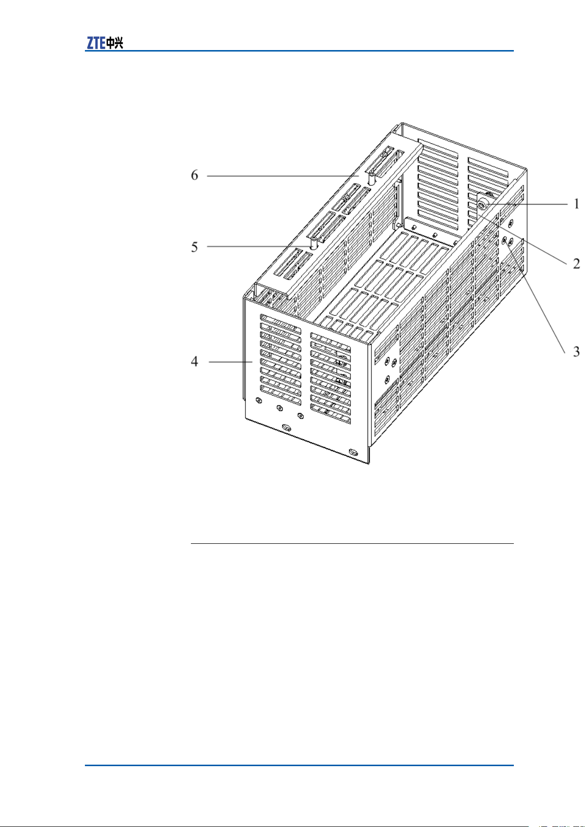
FIGURE43LOWERFIXINGFRAME
Chapter3CabinetInstallation
1.M6×16pan—headscrew
2.Supportingpanel1
3.M4×12pan—headscrew
4.Lowerxingframe
5.M6×16pan—headscrew
6.Supportingpanel2
InstallingIntegratedCabinet
PrerequisiteUnpackingandacceptancefortheZXSDRR8860andthesimplied
cabinetmeetrequirements.
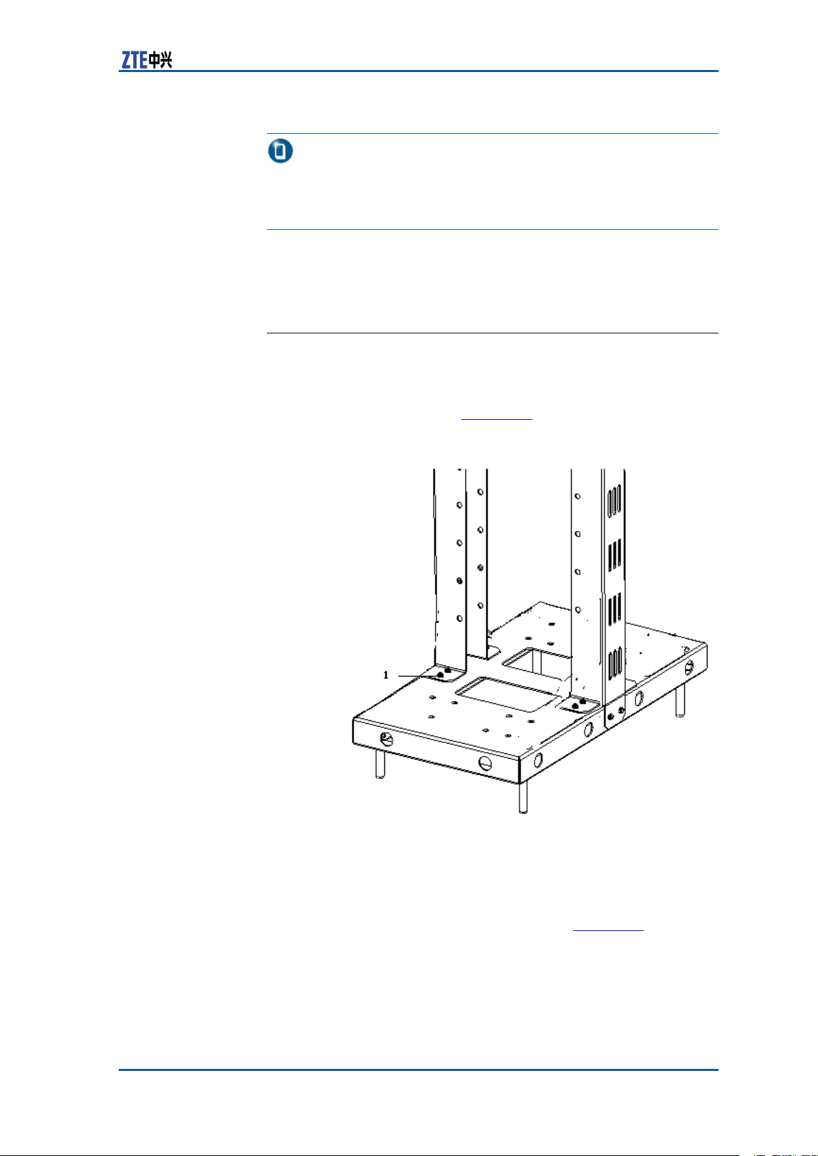
Steps1.Installthesimpliedcabinet.
Accordingtoaninstallationpositionintheengineeringdesign
document,drillholesontheindooroor .Theholepositions
andthedimensionareasshownin.Fastenthecabinetonthe
oorwithM10×100expansionbolts.
ConfidentialandProprietaryInformationofZTECORPORATION57
Page 66

ZXSDRR8860InstallationManual
FIGURE44HOLEPOSITIONSANDDIMENSION
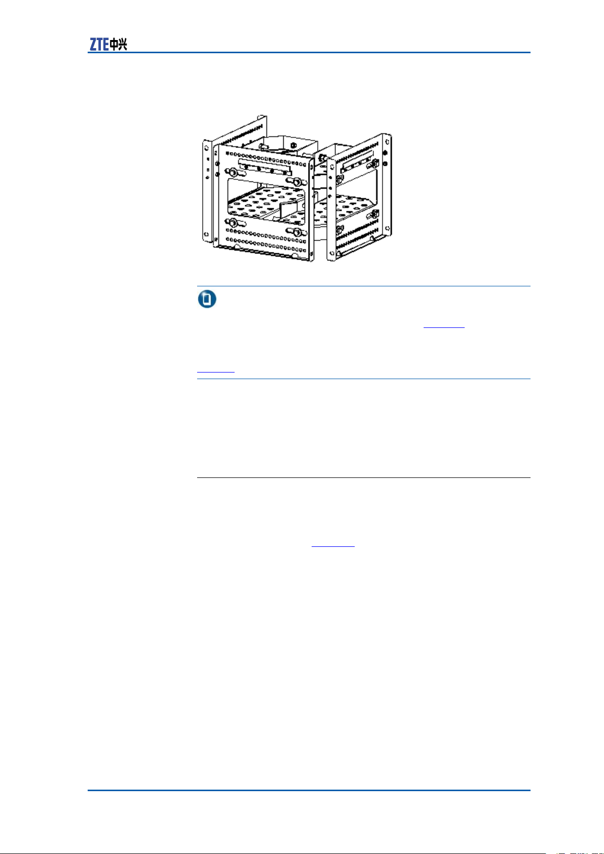
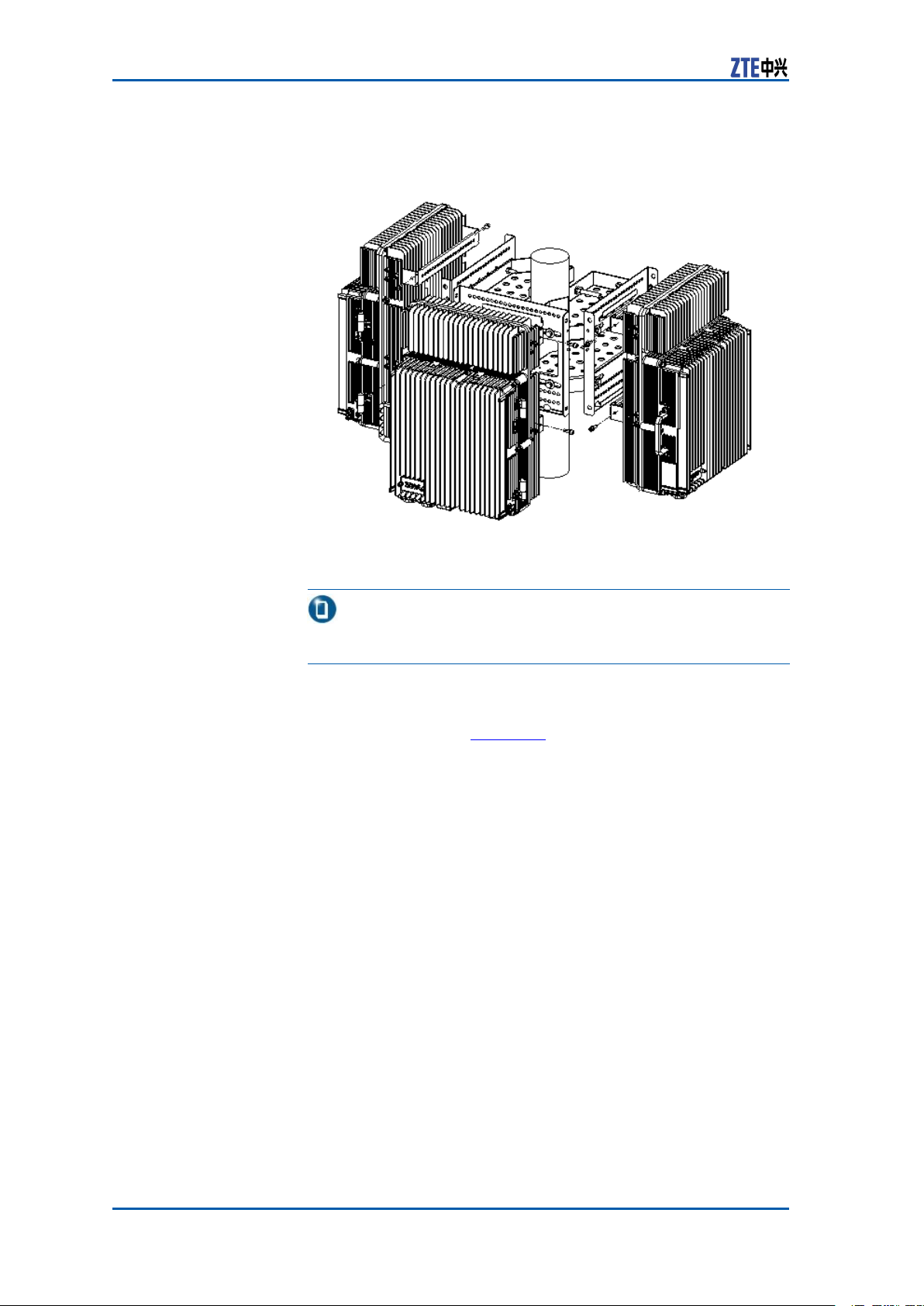
2.InstalltheZXSDRR8860.
showsallassembliesforZXSDRR8860integrated-cabinetinstallation.
58ConfidentialandProprietaryInformationofZTECORPORATION
Page 67

FIGURE45ZXSDRR8860ASSEMBLIES
Chapter3CabinetInstallation
1.Upperxingframe
2.Lowerxingframe
3.ZXSDRR8860
i.RemovethexingbeamsofZXSDRR8860.
TheZXSDRR8860carriestwoxingbeamsusedforwallmountandpole-mountinstallations,asshownin.Remove
thexingbeams.
ConfidentialandProprietaryInformationofZTECORPORATION59
Page 68

ZXSDRR8860InstallationManual
FIGURE46ZXSDRR8860FIXINGBEAM
1.Fixingbeam
ii.Installthelowerxingframe.
InserttheZXSDRR8860tothelowerxingframe.Fasten
thesupportingpanel2withtheZXSDRR8860byM6×12
pan-headscrewsandfastenthesupporting1withZXSDR
R8860byM6×16pan-headscrews,asshownin.
60ConfidentialandProprietaryInformationofZTECORPORATION
Page 69

FIGURE47LOWERFIXINGFRAMEINSTALLATION
Chapter3CabinetInstallation
1.Pan-headscrewM6×162.an-headscrewM6×12
iii.Installtheupperxingframe.
InserttheZXSDRR8860tothelowerxingframe.Fasten
thesupportingpanelofupperxingframewiththeZXSDR
R8860byM6×16pan-headscrews,asshownin.
ConfidentialandProprietaryInformationofZTECORPORATION61
Page 70

ZXSDRR8860InstallationManual
FIGURE48ZXSDRR8860INSTALLEDWITHUPPERANDLOWER
FIXINGFRAME
1.M6×16pan-headscrew
3.InstalltheZXSDRR8860tothesimpliedcabinet.
AligntheguidancechannelontheZXSDRR8860installedwith
theupperandlowerxingframestotherailonethesimplied
cabinet.ThenslidetheZXSDRR8860slowlyintothesimplied
cabinetandfastenthemwithfourM6×16pan-headscrews,as
shownin.
62ConfidentialandProprietaryInformationofZTECORPORATION
Page 71

Chapter3CabinetInstallation
FIGURE49ZXSDRR8860INSTALLATIONTOSIMPLIFIEDCABINET
1.M6×16pan-headscrew
4.InstallotherZXSDRR8860s.
RepeattheStep2~Step4toinstallotherZXSDRR8860sinto
thesimpliedcabinet.WhensixZXSDRR8860sareinstalled
completely,theappearanceisasshownin.
ConfidentialandProprietaryInformationofZTECORPORATION63
Page 72

ZXSDRR8860InstallationManual
FIGURE50ZXSDRR8860INSTALLATIONCOMPLETION
ENDOFSTEPS.
64ConfidentialandProprietaryInformationofZTECORPORATION
Page 73
Chapter3CabinetInstallation
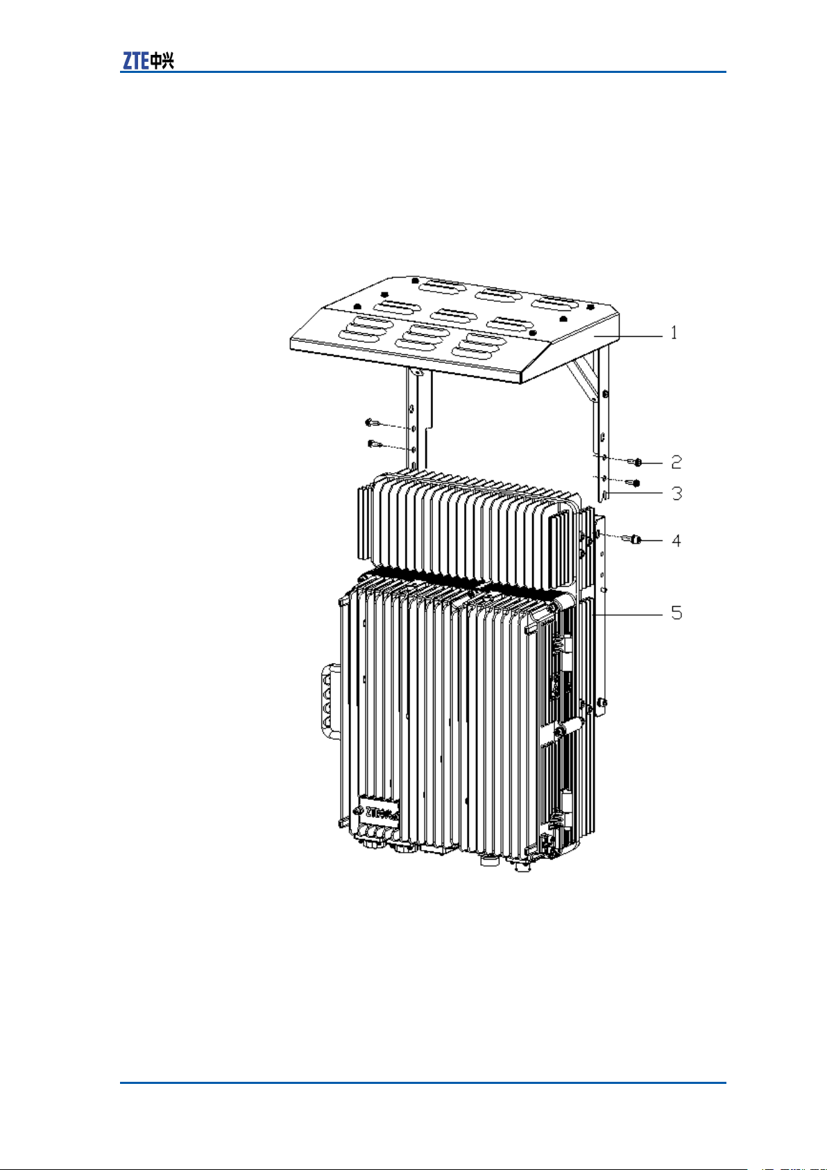
InstallingSunshield
ContextThecomponentsusedforinstallingsunshademustbeprepared.
showsthesunshadetobeinstalled.
FIGURE51SUNSHIELDSTRUCTURE
1.Sunshield
2.M5screw
3.Fixingposition(wedgedontothe
boltatthesideofthecommonpart
forwallmounting)
Steps1.Assemblethesunshadeonsiteandxthebrackettothe
4.M6screw
5.ZXSDRR8860cabinet
shield.
ConfidentialandProprietaryInformationofZTECORPORATION65
Page 74

ZXSDRR8860InstallationManual
2.UnscrewthetwoM6screwatthesidetopofthecabinetand
inserttheboltsatbothsidesofthewall-mountingcommon
parttothesunshade.
3.ScrewthetwoM6screwsandfourM5screwsonbothsidesof
thecabinetandtightenthem.
ENDOFSTEPS.
66ConfidentialandProprietaryInformationofZTECORPORATION
Page 75

Chapter4
ExternalCable Installation
TableofContents:
ExternalCableLayout........................................................67
ExternalCableInstallationFlow...........................................69
InstallingPowerCable........................................................70
InstallingGroundingCable..................................................71
InstallingFiberbetweenBBUandRRU..................................72
InstallingFiberbetweenRRUandRRU..................................73
InstallingEnvironmentMonitoringCable...............................75
InstallingAISGControlCable..............................................76
InstallingFrequencyPointExtensionCable............................77
InstallingJumper...............................................................78
ExternalCableLayout
TheconnectionrelationshipofZXSDRR8860externalcablesis
describedinT able12.
TABLE12ZXSDRR8860EXTERNALCABLECONNECTIONRELATIONSHIP
Name
PowercableConnectstheZXSDR
Connection
Relationship
R8860powerinterface
(DCIN)tothepower
supplyequipment
interface
Description
Oneendisthe
aviationplugandthe
otherendisreserved
forpowercablemade
onsite.Thelengthof
cableisbasedonthe
engineeringsurvey.
ConfidentialandProprietaryInformationofZTECORPORATION67
Page 76

ZXSDRR8860InstallationManual
Name
Connection
Relationship
Groundingcable
ConnectsoneZXSDR
R8860groundboltto
thecopperbar
OpticalFiberTherearetwotypes
ofZXSDRR8860fiber:
BBUconnection
/ZXSDRR8860
cascading.
Environment
monitoringcable
ConnectstheZXSDR
R8860environment
monitoringinterface
MONtothe
externalmonitoring
componentsorthe
drycontact.
AISGcontrolcableConnectstheZXSDR
R8860debugging
interface(AISG)
tothecontrol
interfaceof
electrical-adjustment
antenna.
Frequencypoint
extensioncable
Interconnects
theZXSDRR8860
RXin/RXout
interfaces.
Antenna,feederand
jumper
ConnectstheZXSDR
R8860tothemain
feeder.
Description
Thegroundingcableis
madeupofstrandsof
flame-retardantwire.
Thecrosssectional
areaofZXSDRR8860
groundingcableis
10mm
2
.The
colorofgrounding
cableisyellowand
green.Copperlugs
arecrimpedatboth
endsoftheZXSDR
R8860grounding
cable.
Therearetwotypesof
ZXSDRR8860optical
fiber:oneusedin
BBUconnectionand
theotherusedin
cascadingbetween
ZXSDRR8860s.
Aendofthe
environment
monitoringcable
isPINdesign.Bend,
with3mlengthin
total,needsmaking
basedontheon-site
engineering.
AISGisusedfor
controlofthe
electrical-adjustment
antenna.
Thefrequencypoint
extensioncable
usuallyadoptsthe
finished1/2″jumper
with2mlength.
Thejumpercanbe
self-madebased
onthereal-time
conditiononsite.
AandBends
ofjumperareN
connectors(male).
TheRFjumperusually
adoptsthefinished
1/2″jumperwith2m
length.Thejumper
canbeself-made
basedonthereal-time
conditiononsite.
TheendofjumperisN
connector(male)and
theotherendisDIN
connector(female).
68ConfidentialandProprietaryInformationofZTECORPORATION
Page 77

Chapter4ExternalCableInstallation
ExternalCableInstallation Flow
Figure52liststheinstallationowofexternalcable.Thisowcan
beadjustedbasedonthereal-timecondition.
FIGURE52EXTERNALCABLEINSTALLATIONFLOW
ConfidentialandProprietaryInformationofZTECORPORATION69
Page 78

ZXSDRR8860InstallationManual
InstallingPowerCable
ContextTheZXSDRR8860cabinetadopts-48VDCforpowersupply .End
AistheaviationplugandEndBisreservedforself-madepower
cableonsite.Thelengthofpowercableisaccordingtotheengineeringsurvey.
ZXSDRR8860F
FIGURE53POWERCABLESTRUCTURE
Table13describesthecolorsandspecicationsofinsidecoreca-
ble.
TABLE13COLORANDSPECIFICATION
igure53showsthestructureofpowercable.
Color
Blue
Black
Note:
1.Ifthetwo-corecableisadopted,thebluecorecablestands
for-48Vandtheblackcorecablestandsfor-48VGND;
2.Ifthefour-corecableisadopted,thetwobluecorecables
connectedinparallelstandfor-48Vandtheblackcorecables
connectedinparallelstandfor-48VGND.
Steps1.ConnectEndAofpowercablewithDCINinterfacelocatedat
thebottomofZXSDRR8860.
2.StriptheprotectivecoatofEndBandconnectitwiththeDC
inputpowersourceaccordingtocolorsoftheinsidecorecable.
3.MakewaterproofprotectionofEndB.
4.Attachlabelsatbothendsofthepowercable.
5.Fixthepowercable.
ENDOFSTEPS.
Specification
-48V
-48VGND
70ConfidentialandProprietaryInformationofZTECORPORATION
Page 79

Chapter4ExternalCableInstallation
InstallingGroundingCable
ContextThegroundingcableismadeupofstrandsofame-retardantwire.
ThecrosssectionalareaofZXSDRR8860groundingcableis10
2
mm
lugsarecrimpedatbothendsoftheZXSDRR8860groundingcable,asshowninF
FIGURE54GROUNDINGCABLESTRUCTURE
Steps1.Coverandxacopperlugontheagroundingboltofthe
.Thecolorofgroundingcableisyellowandgreen.Copper
igure54.
ZXSDRR8860cabinet,asshowninFigure55.
FIGURE55ZXSDRR8860GROUNDINGBOLT
1.Groundingbolt
ConfidentialandProprietaryInformationofZTECORPORATION71
Page 80

ZXSDRR8860InstallationManual
2.Connecttheothercopperlugtotheearth-networkingcopper
barandxitwithabolt,asshowninFigure56.
FIGURE56EARTH-NETWORKCOPPERBAR(UNIT:MM)
3.Attachthelabelonthegroundingcable.
4.Measurethegroundingresistanceandmakesureitlessthan
5Ω.
ENDOFSTEPS.
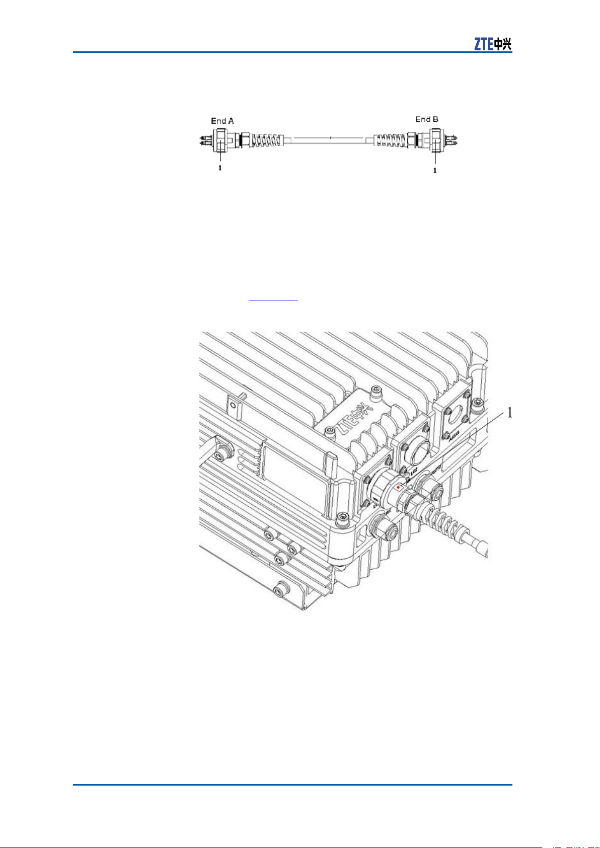
InstallingFiberbetween BBUandRRU
PrerequisiteTheZXSDRR8860cabinetmustbeinstalledandxedsuccessfully.
ContextFigure57showsberconnectionbetweenZXSDRR8860andBBU.
FIGURE57FIBERCONNECTIONBETWEENZXSDRR8860ANDBBU
1.OutdoorSealComponent
WhileconnectingaBBUtoZXSDRR8860,makesurethatthebase-
bandRFberinterface(LC1/2)oftheZXSDRR8860isconnected
totheopticalinterfaceconnectoroftheBBU.
72ConfidentialandProprietaryInformationofZTECORPORATION
Page 81

Chapter4ExternalCableInstallation
Steps1.Attachlabelsatbothendsoftheber .
2.AdjustthesideofEndAwiththecolormarkandinsertthe
ZXSDRR8860berinterface,andscrewdownthenuts,as
showninF
FIGURE58OPTICALFIBERINSTALLATION
igure58
1.Colormark
3.ConnectEndAofthebertothebasebandRFberinterface
(LC1/2)oftheZXSDRR8860.
4.ConnectEndBoftheber ,whichisaDLCconnector ,tothe
BBUopticalconnector .
5.ScrewdowntheoutdoorsealcomponentatEndAforwaterproong.
ENDOFSTEPS.
InstallingFiberbetween RRUandRRU
PrerequisiteThecascadingZXSDRR8860cabinetsmustbeinstalledandxed
successfully.
ContextFigure59showsberconnectionbetweenZXSDRR8860s.
ConfidentialandProprietaryInformationofZTECORPORATION73
Page 82
ZXSDRR8860InstallationManual
FIGURE59FIBERCONNECTIONBETWEENZXSDRR8860S
1.OutdoorSealComponent
WhileinterconnectingtheZXSDRR8860s,makesurethatthetwo
basebandRFberinterfaces(LC1/2)oftheZXSDRR8860areconnected.
Steps1.Attachlabelsatbothendsoftheopticalber .
2.AdjustthesideofEndAwiththecolormarkandinsertthe
ZXSDRR8860berinterface,andscrewdownthenuts,as
showninFigure60.
FIGURE60OPTICALFIBERINSTALLATION
1.Colormark
3.ConnectEndAoftheopticalbertothebasebandRFber
interface(LC1/2)oftheZXSDRR8860.
4.ConnectEndBoftheopticalbertotheotherbasebandRF
berinterface(LC1/2)oftheZXSDRR8860.
74ConfidentialandProprietaryInformationofZTECORPORATION
Page 83

Chapter4ExternalCableInstallation
5.ScrewdowntheoutdoorsealcomponentatEndAforwaterproong.
ENDOFSTEPS.
InstallingEnvironment MonitoringCable
PrerequisiteTheZXSDRR8860cabinetmustbeinstalledandxedsuccessfully.
ContextTheenvironmentmonitoringcableprovidesa485interface,used
forZXSDRR8860environmentmonitoring.Inaddition,thecablealsoprovidesfourextensionaccessesforexternaldrycontact
monitoring.
EndAisthe37PINconnector ,andEndBismadebyon-siteengineering.Thetotallengthis3m.Figure61showstheappearance
ofenvironmentmonitoringcable.
FIGURE61ENVIRONMENTMONITORINGCABLE
Theconnector ,connectingtheenvironmentmonitoringcableto
theZXSDRR8860,adopts37–coreaviationjack.Theconnector
accordswiththeGJB599specication.Theconnectorappearance
isasshowninFigure62
FIGURE62AVIATIONJACKAPPEARANCE
Table14describestheconnectorpins.
ConfidentialandProprietaryInformationofZTECORPORATION75
Page 84

ZXSDRR8860InstallationManual
TABLE14CABLEPINDESCRIPTION
PinCore-CableColorSignalDescription
15/16Whiteandblue/blueDrycontact4-/+
17/18Whiteand
19/20Whiteand
21/22Whiteand
23/24Redandblue/blue
25/26Redandorange/ora
Steps1.ConnectEndAtotheMONinterfacelocatedatthebottomof
ZXSDRR8860.
2.ConnectEndBwithexternalmonitoringdevicesordrycontacts.
3.AttachthelabelatEndB.
ENDOFSTEPS.
orange/orange
Drycontact3-/+
Drycontact2-/+
green/green
Drycontact1-/+
brown/brown
RS485receive
RS485transmit
nge
InstallingAISGControl Cable
ContextTheAISGcontrolcableisusedforcontroloftheelectricaladjust-
mentantenna.
Figure63showsthestructureoftheAISGcontrolcable.
FIGURE63AISGCONTROLCABLESTRUCTURE
Table15describestheserialNo.meaningofAISGcontrolcable.
76ConfidentialandProprietaryInformationofZTECORPORATION
Page 85
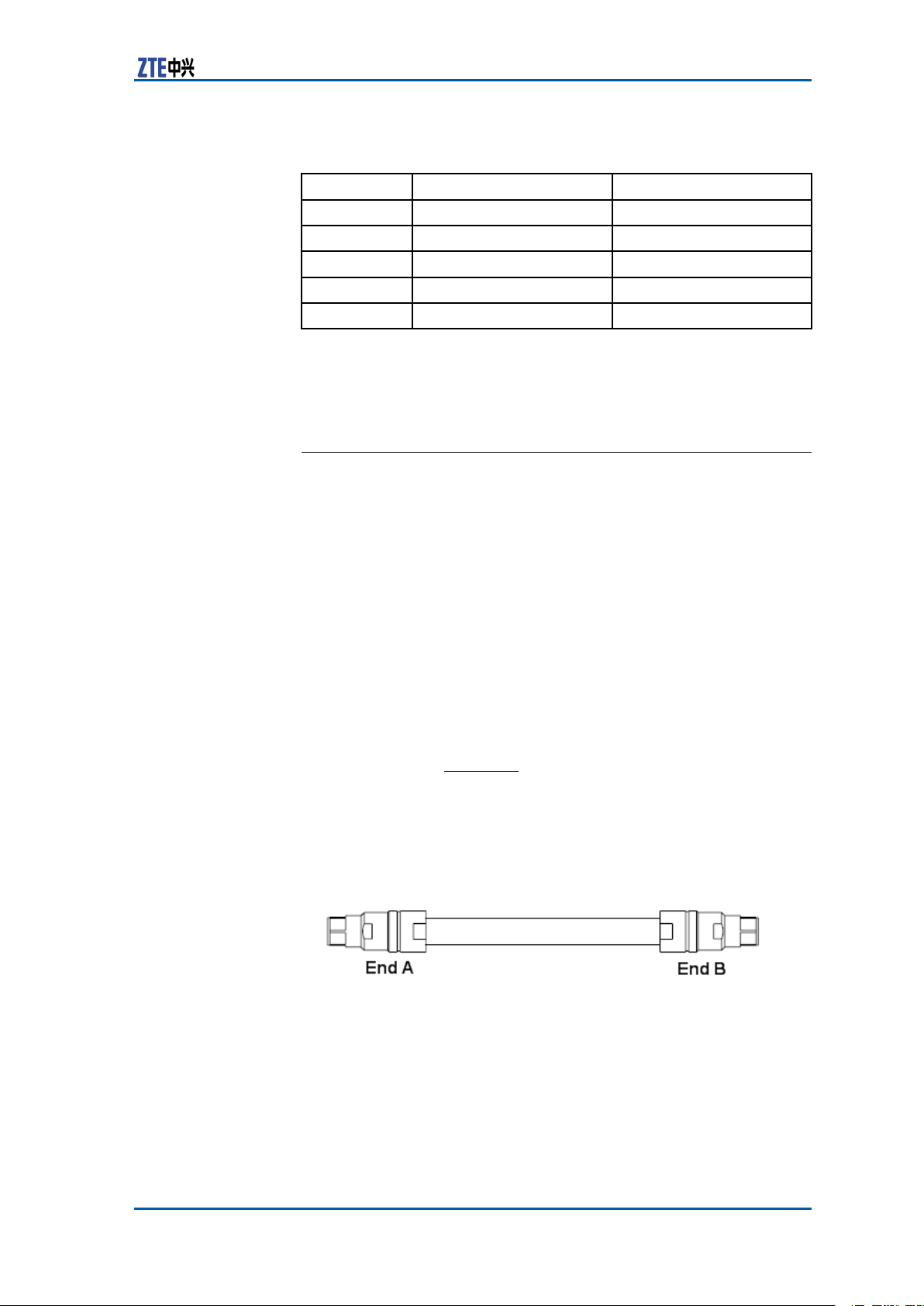
TABLE15AISGCONTROLCABLEDESCRIPTION
Chapter4ExternalCableInstallation
SerialNo.
1
2TRX_ANT_485_-RS485-
3,4TRX_ANT_28V28V
5,6TRX_ANT_28VGND28VGND
7,8NC
Steps1.ConnectEndAtotheZXSDRR8860debugginginterface
(AISG)andscrewdownthebolt;
2.ConnectEndBtothecontrolinterfaceofelectricaladjustment
antennaandscrewdownthebolt.
ENDOFSTEPS.
Name
TRX_ANT_485_+RS485+
Meaning
Null
InstallingFrequencyPoint ExtensionCable
PrerequisiteThetwoZXSDRR8860cabinetstobecombinedmustbeinstalled
andxedsuccessfully .
ContextAfterthecombinationofcabinets,theZXSDRR8860cansupport
8carriersectorsatmost.
ThetwoZXSDRR8860cabinetsareconnectedthroughtheirconnectinginterfacessuchasRXinandRXoutbytwofrequencypoint
extensioncables.Figure64showsthestructureofthefrequency
pointcable.EndAandEndBareNconnectors(male).
The2M1/2″jumperisoftenusedforthefrequencypointextension
cable.Itmaybepreparedonsiteifnecessary.
FIGURE64FREQUENCYPOINTEXTENSIONCABLE
Steps1.ConnectEndAofthefrequencypointextensioncabletothe
frequencypointextensioninterfaceRXINofoneZXSDRR8860;
2.ConnectEndBtoRXoutoftheotherZXSDRR8860;
ConfidentialandProprietaryInformationofZTECORPORATION77
Page 86

ZXSDRR8860InstallationManual
3.ConnecttheremainingRXin/RXoutinterfacesofthetwocombinedcabinetswiththeotherfrequencypointextensioncable.
ENDOFSTEPS.
InstallingJumper
ContextOneendofRFjumperconnectswiththemainfeederandtheother
endconnectswiththeantennafeederinterfaceofZXSDRR8860
cabinet.BeforeinstallingtheRFjumper ,themainfeederisinstalled.
TheRFjumperadoptsthe1/2″jumperwitha2mlength.The
jumpercanalsobeself-madeaccordingtotheon-sitecondition.
TheinstallationpositionofRFjumperisasshowninFigure65.
FIGURE65RFJUMPERINSTALLATION
PerformthefollowingstepstoinstalltheRFjumper .
Steps1.ConnecttheDINconnector(male)ofRFjumperwiththeDIN
connector(female)ofmainfeeder .
2.ConnecttheDINconnector(male)ofRFjumperwiththeDIN
connector(female)ofZXSDRR8860cabinet.
3.SealtheconnectorswithwaterproofadhesivetapesandPVC
tapes.
ENDOFSTEPS.
78ConfidentialandProprietaryInformationofZTECORPORATION
Page 87

Chapter5
MainAntennaFeeder SystemInstallation
TableofContents:
MainAntennaFeederSystemStructure................................79
MainAntennaFeederSystemInstallationPreparation.............85
MainAntennaFeederSystemInstallationFlow......................86
AntennaInstallation...........................................................87
FeederInstallation.............................................................92
InstallingFeederHermetic-window....................................102
FeederIndoorIngoing......................................................104
PerformingAntennaFeederSystemTest.............................108
PerformingOutdoor-connectorWaterproofProcessing...........109
PerformingFeederHermetic-windowWaterproofProcess-
ing................................................................................111
CabinetJumperInstallationDescription..............................114
VSWRTest......................................................................115
ZXSDRR8860
congurationwith
commonantenna
MainAntennaFeeder SystemStructure
ThetypicalcongurationsforZXSDRR8860mainantennafeeder
systemdescribedbelowincludes:
�ZXSDRR8860congurationwithcommonantenna
�ZXSDRR8860congurationwithcommonantenna,AISGdual
poweramplier
�ZXSDRR8860congurationwithelectronicadjustmentan-
tenna(1)
�ZXSDRR8860congurationwithelectronicadjustmentan-
tenna(2)
�ZXSDRR8860congurationwithelectronicadjustmentan-
tenna,AISGdualpoweramplier
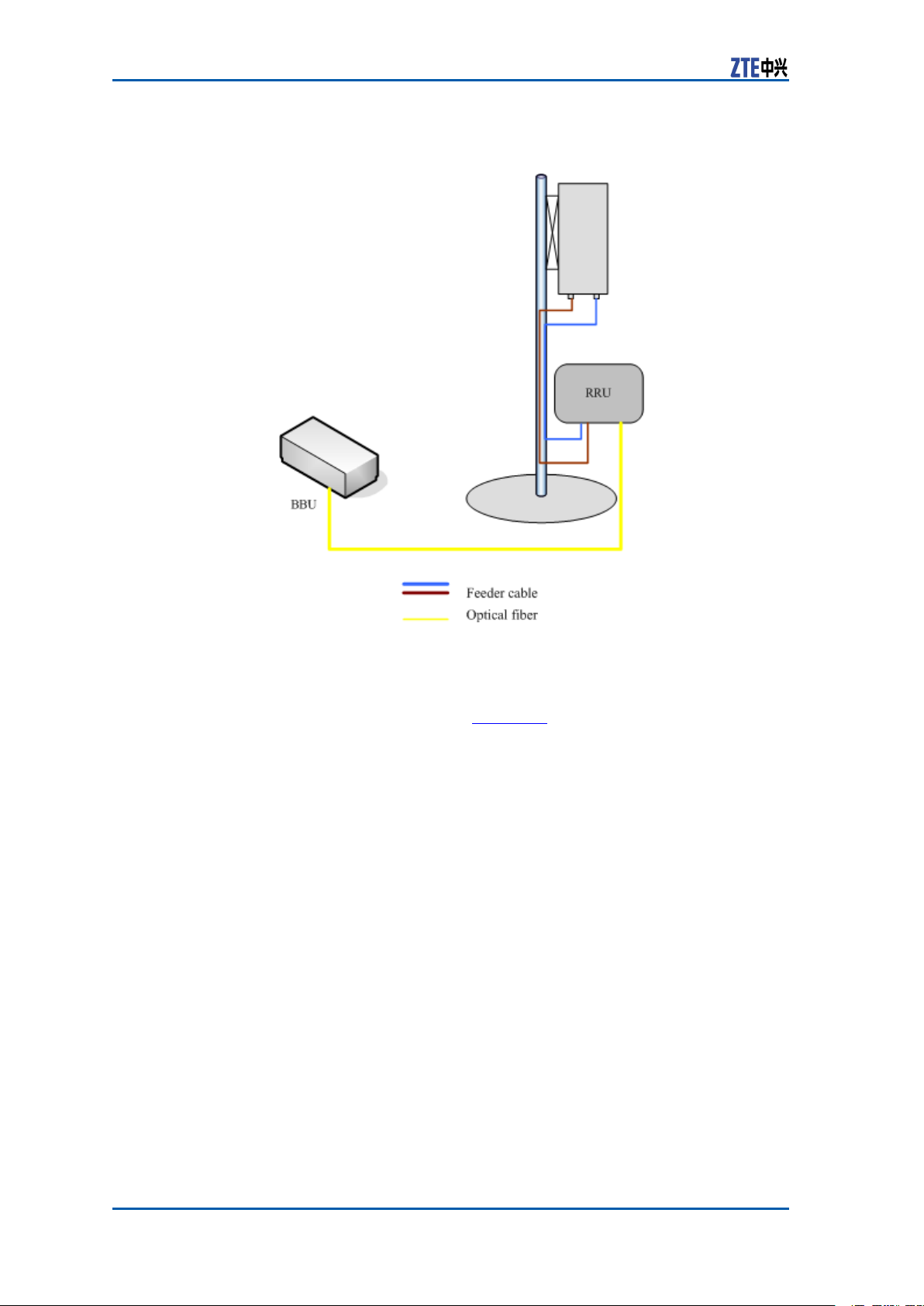
Inthisconguration,generallyZXSDRR8860installationposition
isnearantennaandtheyareallinstalledonthebuildingtop.
ZXSDRR8860isconnectedtotheantennaby1/2″feederdirectly ,
occasionally5/4″or7/8″feederisadopted,asshowninFigure66.
ConfidentialandProprietaryInformationofZTECORPORATION79
Page 88
ZXSDRR8860InstallationManual
FIGURE66ZXSDRR8860CONFIGUREDWITHCOMMONANTENNA
ZXSDRR8860
congurationwith
commonantenna,
.
Inthisconguration,generallyZXSDRR8860isinstalledonthe
tower .ZXSDRR8860isconnectedtotheantennaby5/4″or
7/8″feeder ,asshowninFigure67.
80ConfidentialandProprietaryInformationofZTECORPORATION
Page 89

Chapter5MainAntennaFeederSystemInstallation
AISGdualpower
amplier
FIGURE67ZXSDRR8860CONFIGURATIONWITHCOMMONANTENNA,
AISGDUALPOWERAMPLIFIER
ConfidentialandProprietaryInformationofZTECORPORATION81
Page 90

ZXSDRR8860InstallationManual
withelectronic
ZXSDRR8860
conguration
adjustment
antenna(1)
Inthisconguration,generallyZXSDRR8860installednearthe
antennaonthebuildingtop.ZXSDRR8860isconnectedtothe
antennaby1/2″feederdirectly ,occasionally5/4″or7/8″feederis
adopted,asshowninF
FIGURE68ZXSDRR8860CONFIGURATIONWITHELECTRONIC
ADJUSTMENTANTENNA(1)
igure68.
ZXSDRR8860
conguration
withelectronic
Inthisconguration,generallyZXSDRR8860isinstallednearthe
topofthetower .ZXSDRR8860isconnectedtotheantennaby
5/4″or7/8″feederisadopted,asshowninFigure69.
82ConfidentialandProprietaryInformationofZTECORPORATION
Page 91

Chapter5MainAntennaFeederSystemInstallation
adjustment
antenna(2)
FIGURE69ZXSDRR8860CONFIGURATIONWITHELECTRONIC
ADJUSTMENTANTENNA(2)
ConfidentialandProprietaryInformationofZTECORPORATION83
Page 92

ZXSDRR8860InstallationManual
ZXSDRR8860
conguration
withelectronic
antenna,AISG
Inthisconguration,generallyZXSDRR8860isinstallednearthe
topofthetower .ZXSDRR8860isconnectedtotheantennaby
adjustment
dualpower
amplier
5/4″or7/8″feederisadopted,asshowninFigure70.
FIGURE70ZXSDRR8860CONFIGURATIONWITHELECTRONIC
ADJUSTMENTANTENNA.AISGDUALPOWERAMPLIFIER
84ConfidentialandProprietaryInformationofZTECORPORATION
Page 93

Chapter5MainAntennaFeederSystemInstallation
MainAntennaFeeder SystemInstallation Preparation
ProperantennainstallationisveryimportanttoZXSDRR8860systemreliableoperation.Beforeinstallation,makesurethatinstallationstaffisqualiedandthefollowingrequirementsaresatised.
Personnel
Requirement
Normally,supervisorsareinchargeofdirectionandsupervision,
whereasinstallationpersonnelcarryouttheinstallation.
�InstallationSupervisor
Therequirementsfortheinstallationsupervisorareasfollows:
�Familiarwithallmaterials,toolsandoperationmethods.
�Theyareinchargeofassigningdifferentworktotheproper
employeewhoisgoodattheoperation,especiallywhile
workingontheirontower .
Note:
Safetyisthemostimportantconsiderationwhenassigning
work.
�InstallationPersonnel
Therequirementsfortheinstallationpersonnelareasfollows:
�Installationemployeesarerequiredtoinstallantennasys-
temskillfullyunderthedirectionofsupervisor .
�Employeesontowermustbequaliedandingoodphysical
state.
�Installationafterdrinkingisforbidden.
Environment
Requirement
Payattentiontofollowingitemsandcheckwhethertheysatisfy
requirementsinengineeringdesign.Normally,theyarecompleted
bythenetworkoperator(carrier).
�Lightningprotectionandgrounding
ZXSDRR8860isusuallylocatedoutdoors.Thegrounding
stakeandoutdoorlightning-protectinggroundingcablesare
installedbytheoperator ,andthesupervisorshouldconrm
lightning-protectinggroundingcablesareinstalledproperly.
�Poleandsupportingrack
Accomplishinstallationofantennasupportingrackandpole
accordingtoprojectdesignrequirement.Thestabilityofthe
supportingrackandpoleshouldbeinaccordancewiththedesignrequirement.
�Feederlayout
Fieldengineersneedtodeterminerouteofmainfeederwith
operatorengineersbeforeinstallation.
ConfidentialandProprietaryInformationofZTECORPORATION85
Page 94

ZXSDRR8860InstallationManual
�Electronicpowerenvironment
�ZXSDRR8860antennaandfeedersystemcannotbeinstalled
tooneartopublicelectricpowercables.
Safety
Precautions
ToolsRequire-
ment
Ensurethefollowingprecautionsbeforeantennainstallation:
�Takenecessarymeasuresforpersonalandequipmentsafety.
�Personnelundertowermustwearsafetyhelmets.
�Personnelontowermustwearsafetybelt.
�Neverclimbtowerwithlooseclothesandwet/slipperyshoes.
�Duringactiveantennaadjustment,wearradiation-shielding
clothingandturnoffpowerampliertoavoidradiationeffects.
�Ifpossible,installinsunnyandwindlessdays.Installationis
forbiddeninrain,strongwind,thunderandlightning.
�Makecautionbrandinengineeringeldandkeeppassengers
awayfromengineeringeld,especiallykids.
�Whenworkingontower ,putunusedtoolsinatoolbagand
preventthemfromdroppingdownfromtowertohurtpeople.
Thefollowingtoolsarerequiredformainantennafeedersystem
installation:
�Measuretools
Compass,multimeter ,anglemeter ,andtapemeasure
�Specialtools
Mainfeederconnectormanufacturing,specialtoolsandinstrumentsfortest
�Regulartools
Adjustablewrench,sharp-nosepliers,diagonalpliers,hacksaw
(withseveralsawblades)
�Protectiontools
Safetyhelmet,safetybelt,safetyrope,gloves,radiation-shieldingclothes,multiplepowersocketandsealed
canvastoolbag
�Othertools
Toolsforlifting,e.g.Ladder
MainAntennaFeeder SystemInstallationFlow
Figure71showstheinstallationowofmainantennafeedersys-
tem.
86ConfidentialandProprietaryInformationofZTECORPORATION
Page 95

Chapter5MainAntennaFeederSystemInstallation
FIGURE71MAINANTENNAFEEDERSYSTEMINSTALLATIONFLOW
AntennaInstallation
AntennaInstallationTechnical Specifications
Theantennatechnicalspecicationsandtheirdescriptionisgiven
below.
�Antennaheight
Theinstallationheightofantennaisdeterminedbynetwork
planningdesign.
�Antennaazimuth
Theazimuthoftheantennaisdeterminedbynetworkplanning
design.
�Antennadowntilt
Thedowntiltangleoftheantennaisdeterminedbynetwork
planningdesign.Usuallythedowntiltangleis0°~10°
�Antennadirection
ConfidentialandProprietaryInformationofZTECORPORATION87
Page 96

ZXSDRR8860InstallationManual
Antennadirectiondependsontheantennaazimuth.Iftwo
antennasinonesector ,mustsharethesameazimuth.
AntennaInstallationPosition
Theantennainstallationpositionmustbeinaccordancewith
projectdesign.Iftheinstallationpositionneedsanymodication,
theprojectsupervisormustnegotiatewithoperator’srepresentative.
Theantennainstallationpositionneedstotakecareforelightning
protectionasshowninF
FIGURE72ANTENNAINSTALLATIONPOSITION
igure72.
1.Lightningrod
2.45°Lightningprotectionarea
Followingarelightningprotectionrequirementstoinstallanantenna:
�Theantennashouldbeinstalledwithin45°coverageareaof
lightningrod.
�Ifthereisnospeciallightningprotectionarrangementlikethe
above,installthelightningprotectionsystemontotheantenna
pole.
�Makesurethatthelightningrodiswellgrounded.
3.Antenna
4.Groundingcable
DirectionalAntennaInstallation
ContextThedirectionalantennainstallationprocedureisgivenbelow.
88ConfidentialandProprietaryInformationofZTECORPORATION
Page 97
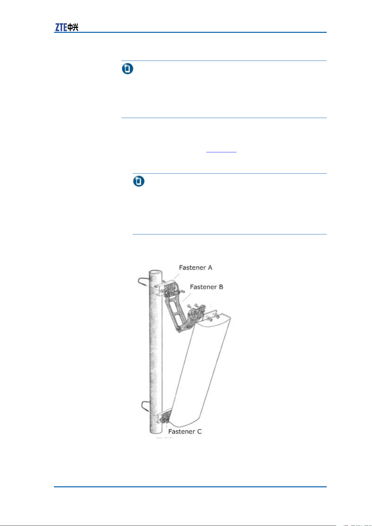
Chapter5MainAntennaFeederSystemInstallation
Note:
Thefollowingstepsdescribetheinstallationprocessasareference
forinstallationpersonnel.Duringtheon-siteinstallationprocess,
pleasecarefullyreadtheinstallationmanualprovidedwiththeantenna,andcarryouttheinstallationaccordingtotheactualcondition.
Performthefollowingstepstoinstalladirectionalantenna:
Steps1.Firstlyassemblefastener"C"ontotheupperandlowerends
ofantennaasshowinFigure73,thenconnectfasteners"B"
and"A"tocompletetheinitialinstallationofthedirectional
antenna.
Note:
�Allaccessoriesmustbeinstalledwithspringandplain
washers.
�Usuallytheantennafasteningaccessoriesandtheangle
adjustmentdeviceaccessorieshavealreadybeeninstalled
ontheantennabeforexingintothetower .
FIGURE73DIRECTIONALANTENNAINSTALLATION
ConfidentialandProprietaryInformationofZTECORPORATION89
Page 98

ZXSDRR8860InstallationManual
2.Attachtheantennaalongwithxturesontothepole.Donot
tightenthescrewstootightlytoalloweasyadjustmentofthe
directionanddowntiltoftheantenna.However ,degreeof
tightnessmustbehighenoughtoensurethattheantennadoes
notsliddownward.
3.Adjusttheantenna’sazimuth.
i.Determinetheazimuthoftheantennabyusingacompass,
ii.T urntheantennaslightlytoadjustit’sfacedirectionas
iii.Afteradjustingtheazimuthoftheantenna,tightenthefas-
4.Adjusttheantenna’sdowntilt
i.Adjustthedowntiltofthemeasurementmetertoobtain
ii.T urnthetopoftheantennaslightly,andlooseorfastthe
anddeterminetheinstallationdirectionaccordingtothe
engineeringdesigndrawing.
showninF
igure73.Atthesametime,measurethedirec-
tionoftheantennawithacompassuntiltheerrorcomes
withintheengineeringdesignrequirements(generallynot
morethan5°).
tener"A".
therequiredangleaccordingtotheengineeringdesign.
antennaatitstop.Adjustthedowntiltangleoftheantenna
tillthemeasurementmeter’sbubblecomestobecentered
asshowninFigure74.
FIGURE74ANTENNADOWNTILTADJUSTMENT
iii.Afteradjustingthedowntiltoftheantenna,tightenthefas-
tener"B.
ENDOFSTEPS.
ResultThedirectionalantennaisinstalled.
90ConfidentialandProprietaryInformationofZTECORPORATION
Page 99

Chapter5MainAntennaFeederSystemInstallation
OmniAntennaInstallation
ContextPerformfollowingstepstoinstallanOmnidirectionalantenna:
Steps1.Determinetheinstallationposition.
2.Sealtheantenna’slowerpart(jumper)withthejacketand
placetheantennaasmuchclosetothesupportingpole.
3.Ensurethatthetopofthejacketslightlyhigherthanthetop
ofsupportingpole.
4.Fastentheantennaontothesupportingpolewithtwoxing
clipsasshowninFigure75.Donotfastentheclipswhether
tootightlyorloosely.Iffastenedtootightly,thejacketmaybe
damaged;iffastentooloosely,theweight-bearingandwindresistancerequirementscannotbemet.
FIGURE75OMNIDIRECTIONALANTENNAINSTALLATION
1.Antenna
2.Fixingclips
5.Measuretheverticalityoftheantenna,andensurethatantennaisvertical.
6.Afterensuringtheverticalitytightenthexingclipsrmly.
7.Aftertheantennaisinstalledontothesupport,xtheantenna
supportontothetower .
ENDOFSTEPS.
ResultTheOmnidirectionalantennaisinstalled.
3.Antennapole
ConnectJumperandAntenna
ContextPerformthefollowingstepstoconnectjumperwithantenna.
ConfidentialandProprietaryInformationofZTECORPORATION91
Page 100

ZXSDRR8860InstallationManual
Theantennajumpercanbeconnectedbeforetheantenna
mountedontothepole,andneededtotakethewaterproof
measurements.Thishighlyreducestheworktime,providegood
connection,andimproveswaterpreventionquality.
Steps1.Connectthejumperconnectortotheantennaport,andtighten
itproperly.
2.Sealthejumperconnectorandantennaportforwaterproof
treatment.
i.Wrapthewaterproofadhesivetapeslowersideofconnec-
ii.Whilewrapping,extendtheadhesivetapestodoubletheir
iii.Gripthetapewithyourhandstomakethetapetightly
iv.WrapPVCtapesontopofthewaterproofadhesivetape.
ENDOFSTEPS.
Note:
tors.Keepwrappingdirectionsameastheonethatthe
jumperistightened.
length.Notethateverywrappinglayermustbeoverlapped
thepreviouslayerbyhalfthewidthofthetapeWrappingmustbeextendedupto50mm(2inches)awayfrom
jumperconnectorposition.
adhered.
Duringtheprocess,makesuretheupperlayeroverlaps
thelowerlayerbyhalfthewidthofthetape.
ResultThejumperisconnectedwithantenna.
FeederInstallation
FeederCuttingPrinciple
Determinelengthofthefeederaccordingtonalfeederroute,and
cutthefeedersaccordingtothelengthrequiredofeachfeeder .
Note:
Ifthefeederlengthislessthan10meters,use1/2”feeder;ifthe
feederlengthis10~30meters,use7/8”feederandifthefeeder
lengthismorethan30meters,use5/4”feeder .
Followingarethetypicalfeedercuttingscenarioobservedon-site:
�Iftheantennafeedersystemistobeinstalledonthe
buildingroof
92ConfidentialandProprietaryInformationofZTECORPORATION
 Loading...