

Zte ZXSDR BS8800 C100 Hardware Manual

ZXSDRBS8800C100
CDMAIndoorBasestation-8800
HardwareManual
ZTECORPORATION
ZTEPlaza,KejiRoadSouth,
Hi-TechIndustrialPark,
NanshanDistrict,Shenzhen,
P .R.China
518057
Tel:(86)75526771900
Fax:(86)75526770801
URL:http://ensupport.zte.com.cn
E-mail:support@zte.com.cn

LEGALINFORMATION
Copyright©2006ZTECORPORATION.
Thecontentsofthisdocumentareprotectedbycopyrightlawsandinternationaltreaties.Anyreproductionordistributionof
thisdocumentoranyportionofthisdocument,inanyformbyanymeans,withoutthepriorwrittenconsentofZTECORPORATIONisprohibited.Additionally ,thecontentsofthisdocumentareprotectedbycontractualcondentialityobligations.
Allcompany ,brandandproductnamesaretradeorservicemarks,orregisteredtradeorservicemarks,ofZTECORPORA TION
oroftheirrespectiveowners.
Thisdocumentisprovided“asis”,andallexpress,implied,orstatutorywarranties,representationsorconditionsaredisclaimed,includingwithoutlimitationanyimpliedwarrantyofmerchantability ,tnessforaparticularpurpose,titleornon-infringement.ZTECORPORATIONanditslicensorsshallnotbeliablefordamagesresultingfromtheuseoforrelianceonthe
informationcontainedherein.
ZTECORPORATIONoritslicensorsmayhavecurrentorpendingintellectualpropertyrightsorapplicationscoveringthesubject
matterofthisdocument.ExceptasexpresslyprovidedinanywrittenlicensebetweenZTECORPORA TIONanditslicensee,
theuserofthisdocumentshallnotacquireanylicensetothesubjectmatterherein.
ZTECORPORATIONreservestherighttoupgradeormaketechnicalchangetothisproductwithoutfurthernotice.
UsersmayvisitZTEtechnicalsupportwebsitehttp://ensupport.zte.com.cntoinquirerelatedinformation.
TheultimaterighttointerpretthisproductresidesinZTECORPORATION.
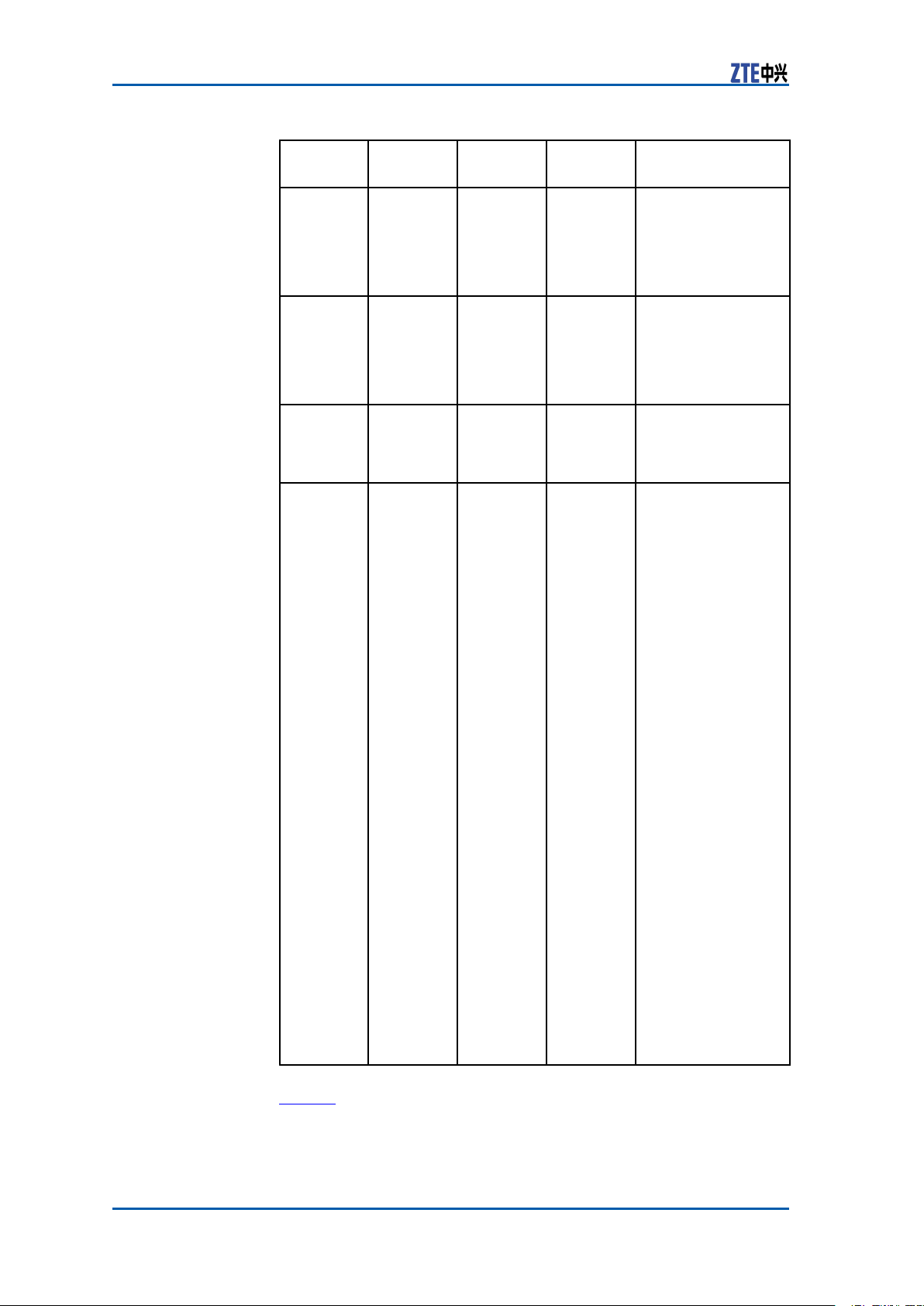
RevisionHistory
RevisionNo.RevisionDateRevisionReason
R1.1
R1.0
01/30/2009OptimizeManual
09/30/2008FirstEdition
SerialNumber:sjzl20083045

Contents
Preface...............................................................i
Cabinet..............................................................1
ZXSDRBS8800C100CabinetTechniqueFeature................1
ZXSDRBS8800C100BasebandRFCabinetOuter
Structure...............................................................1
ZXSDRBS8800C100BasebandRFCabinetInner
Structure...............................................................2
ZXSDRBS8800C100RFSubrack.................................3
WiringSlot................................................................4
ZXSDRBS8800C100PowerDistributionSubrack............4
ZXSDRBS8800C100BasebandSubrack........................6
FanSubrack...............................................................6
Wind-guidePlate........................................................7
TransmissionSubrack(optional)...................................7
Modules.............................................................9
ControlandClockModule(CC).........................................9
ChannelProcessingModule(CH)......................................13
FabricSwitchModule(FS)...............................................17
SiteAlarmModule(SA)..................................................21
FanArrayModule(FA)....................................................27
PowerModule(PM)........................................................28
RadioSystemUnit(RSU)................................................31
ExternalCables...............................................35
ExternalCableLayout....................................................35
DCPowerCable.............................................................36
GroundingCable............................................................37
75ΩE1Cable................................................................37
120ΩE1Cable..............................................................41
100ΩT1Cable..............................................................45
EthernetCable..............................................................46
DryContactInput/OutputCable......................................47

RS232/RS485MonitoringCable.......................................48
DataCable...................................................................49
Fiber............................................................................56
AISGControlCable........................................................56
GPSJumper..................................................................58
RFJumper....................................................................58
GPSAntennaFeederCablesand
Components....................................................61
GPSAntennaFeederSystemStructure.............................61
GPSAntenna................................................................62
GPSFeeder...................................................................63
GPSArrester.................................................................64
GPSFeederConnector....................................................65
GPSGroundingKit.........................................................66
MainAntennaFeederSystem..........................69
MainAntennaFeederSystemStructure............................69
Antenna.......................................................................70
FeederStructure...........................................................71
Figures............................................................73
Tables.............................................................75
ListofGlossary................................................77

PrerequisiteSkill
andKnowledge
WhatisinThis
Preface
PurposeTheZXSDRBS8800C100isaradiotransceiverdevicetoprovide
serviceforacertaincell.TheZXSDRBS8800C100canfulll
mostfunctionsconcerningCDMApatenttechnologies.TheprimaryfunctionsofZXSDRBS8800C100are:basebandmodulation
anddemodulation,RFsignaltransmissionanddemodulation,radioresourcesdistribution,callprocessing,powercontrolandsoft
handoff.
Thismanualintroducessomehardware,suchasfunctionsand
structuresofZXSDRBS8800C100cabinet,modules,cablesand
antennafeedersystem.
Intended
Audience
Manual
ThisdocumentisintendedforengineersandtechnicianswhoperformoperationactivitiesZXSDRBS8800C100.
Tousethisdocumenteffectively ,usersshouldhaveageneralunderstandingofZXSDRBS8800C100equipmentanditscomponents.Familiaritywiththefollowingishelpful:
�cdma2000fundamental
�ZXSDRBS8800C100hardwarestructure
Thismanualcontainsthefollowingchapters:
Chapter
Chapter1
Cabinet
Chapter2
Modules
Chapter3
External
Cable
Chapter4
GPSAntenna
Feeder
System
Chapter5
MainAntenna
Feeder
System
Summary
Describesthetechnologyfeaturesandstructureof
cabinet.
Describesprinciples,functions,panelsandindicators
ofvariousmodules.
Describesapplication,structureandtechnical
parametersofexternalcables.
DescribescablesandcomponentsofGPSantenna
feedersystem.
Describescablesandcomponentsofmainantenna
feedersystem.
CondentialandProprietaryInformationofZTECORPORATIONi

ZXSDRBS8800C100HardwareManual
Thispageisintentionallyblank.
iiCondentialandProprietaryInformationofZTECORPORATION

Chapter1
Cabinet
TableofContents
ZXSDRBS8800C100CabinetTechniqueFeature....................1
ZXSDRBS8800C100BasebandRFCabinetOuterStruc-
ture..................................................................................1
ZXSDRBS8800C100BasebandRFCabinetInnerStruc-
ture..................................................................................2
ZXSDRBS8800C100 CabinetTechniqueFeature
TheZXSDRBS8800C100cabinetuses19inchstandardcabinet.
ThenetdimensionsofZXSDRBS8800C100is950mm(376/16
in)×600mm(2310/16in)×450mm(1711/16in)(height×
WidthXdepth).
Thefrontdoorofthecabinetiscoatedwithdichromaticspray ,and
theinternalpanelsarepavedwithpowdercoat(grayishsand).
Bothsidesofthecabinetareblueincolor .Allmechanicalparts
meetsenvironmentalprotectionrequirementsofZTE’splating
technologyandmaterials.
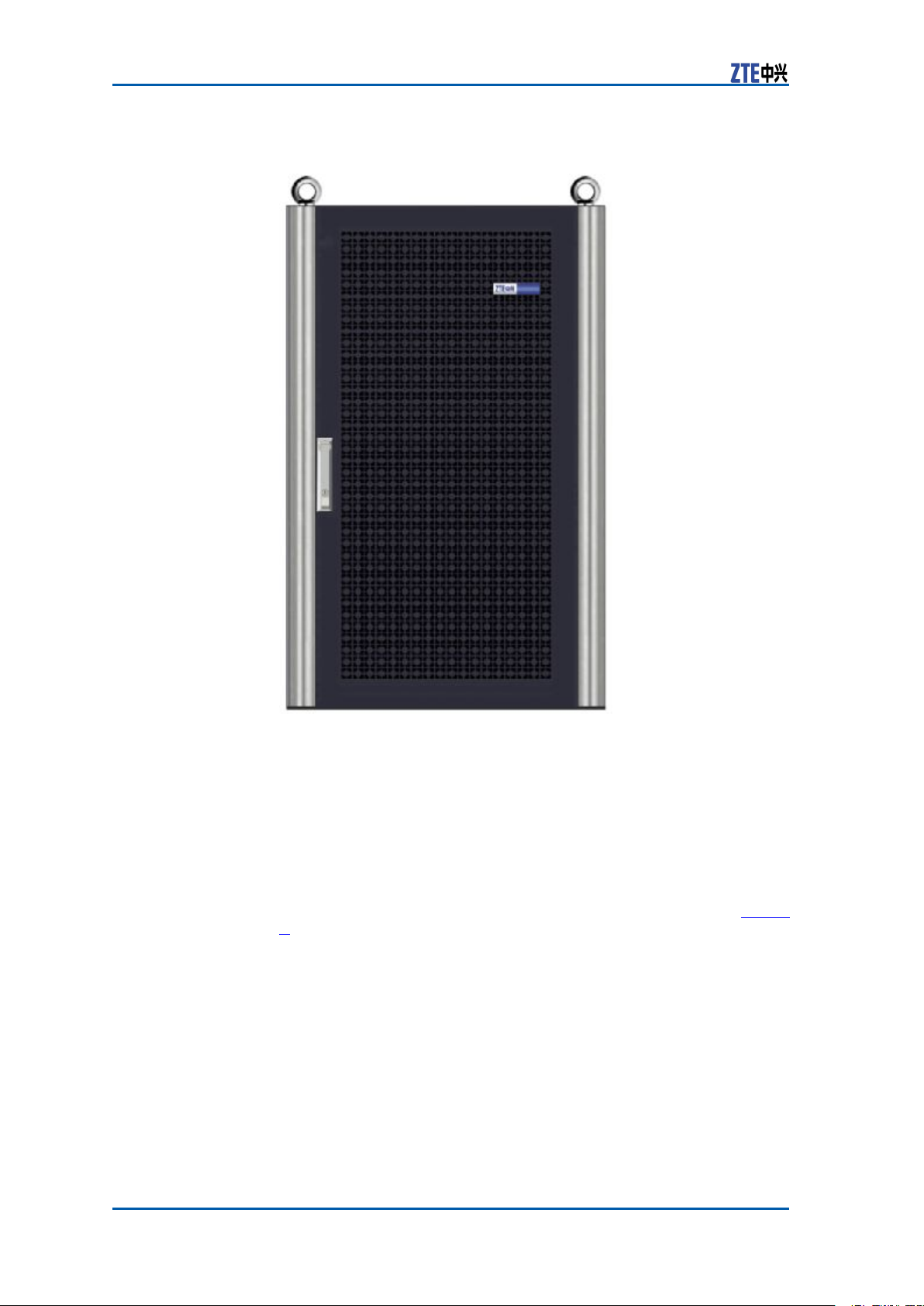
ZXSDRBS8800C100 BasebandRFCabinetOuter Structure
Thedimensionoftheoverallcabinetis950mm(376/16in)
(height)X600mm(2310/16in)(width)X450mm(1711/16in)
(depth).F
outerstructure.
igure1showstheappearanceofZXSDRBS8800C100
CondentialandProprietaryInformationofZTECORPORATION1
ZXSDRBS8800C100HardwareManual
FIGURE1ZXSDRBS8800C100RFCABINETOUTERSTRUCTURE
ZXSDRBS8800C100 BasebandRFCabinetInner Structure
TheinnerstructureoftheZXSDRBS8800C100isshowninFigure
2.
2CondentialandProprietaryInformationofZTECORPORATION
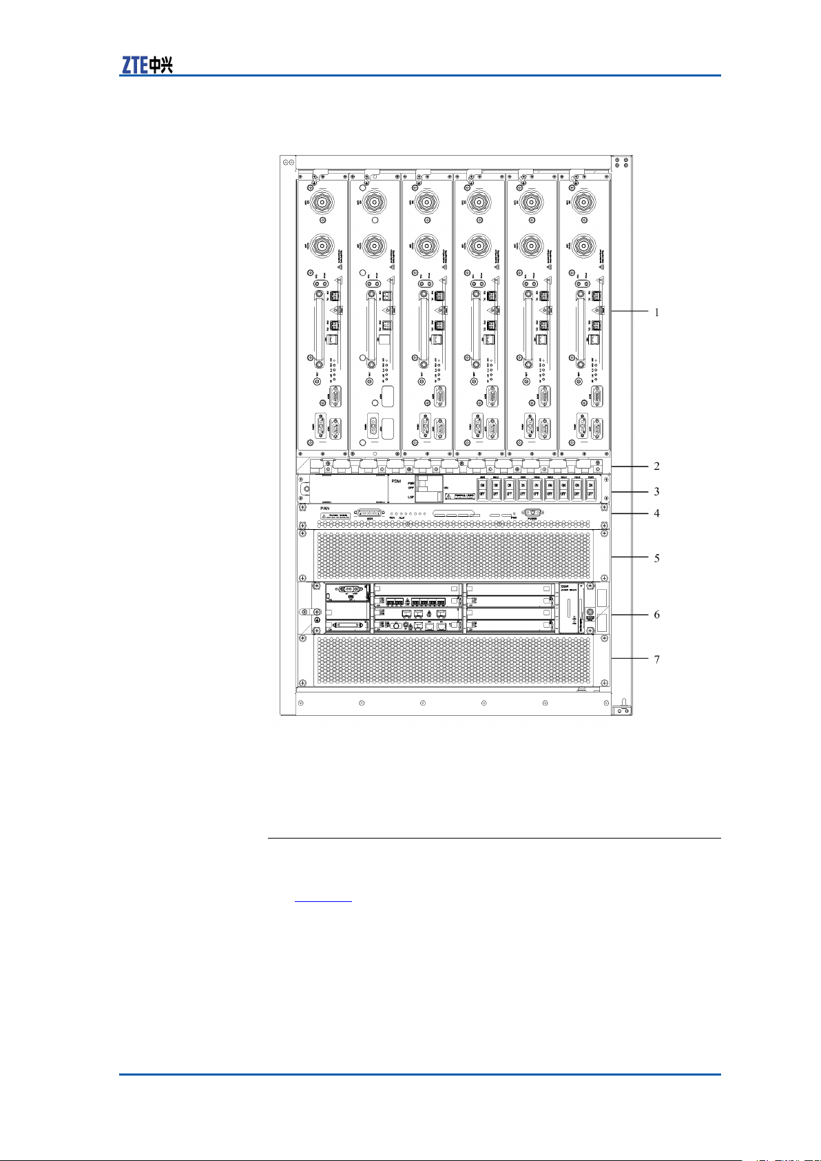
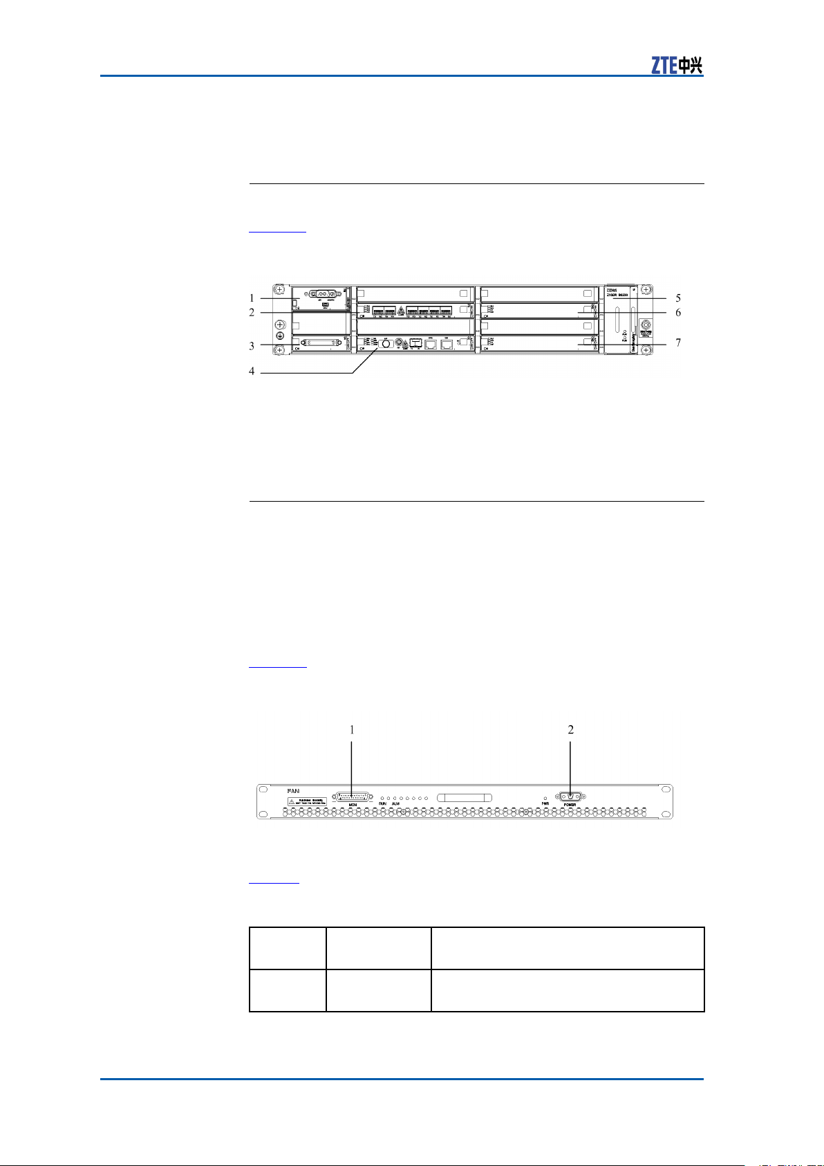
FIGURE2ZXSDRBS8800C100INNERSTRUCTURE
Chapter1Cabinet
1.RFsubrack
2.Cabletray(wiringslot)
3.Powerdistributionsubrack
4.Fansubrack
5.Wind–guideplate
6.Basebandsubrack
7.Transmissionsubrack(reserved)
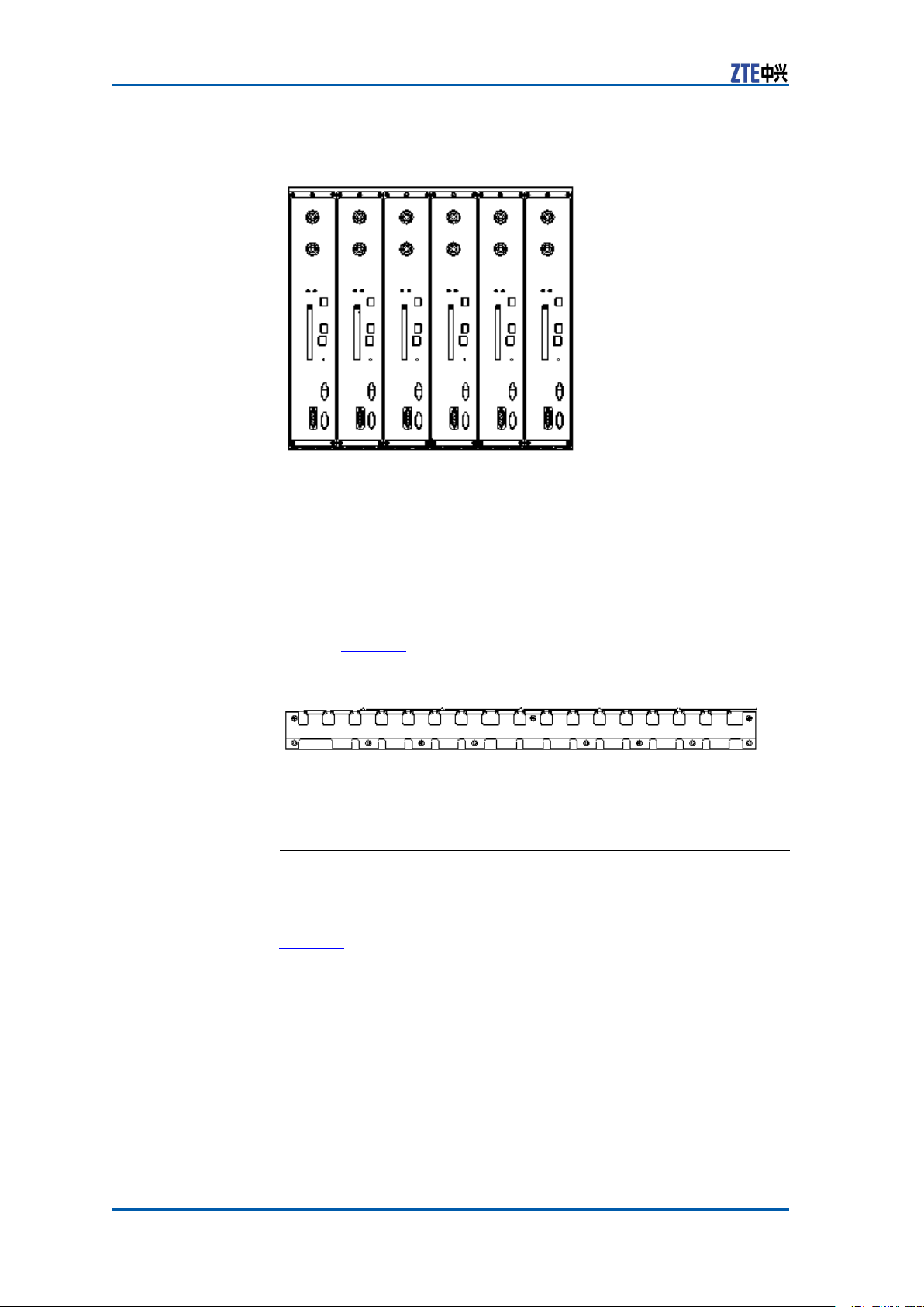
ZXSDRBS8800C100RFSubrack
TheRFunitislocatedorinstalledatthetoplayerofthecabinet.Figure3illustratestheappearanceofZXSDRBS8800C100RF
subrack.
CondentialandProprietaryInformationofZTECORPORATION3
ZXSDRBS8800C100HardwareManual
FIGURE3RFSUBRACKAPPEARANCE
TherearesixslotsinoneRFsubrack,andthese6slotscanbe
conguredwith6RU60multi-carrierRFunitsatmost.
WiringSlot
Wiringslotisusedtolayout,arrange,supportandprotectthe
cables.Figure4illustratesthestructureofwiringslot.
FIGURE4WIRINGSLOT
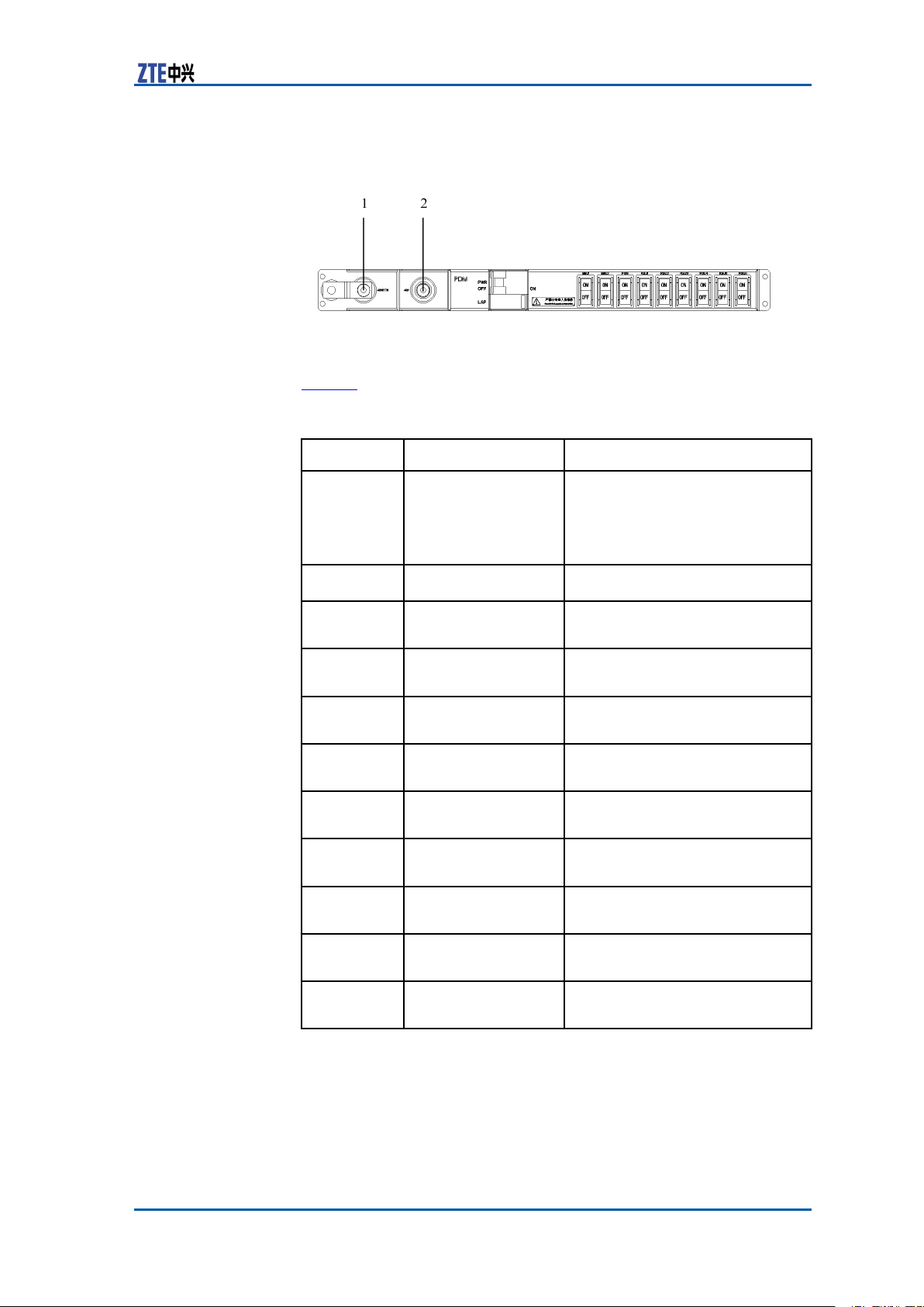
ZXSDRBS8800C100Power DistributionSubrack
ThepowerdistributionsubrackisresponsibleforpowerdistributionofthewholeBTS.
Figure5illustratesthefrontpanelofthepowerdistributionsub-
rack.
4CondentialandProprietaryInformationofZTECORPORATION
Chapter1Cabinet
FIGURE5POWERDISTRIBUTIONSUBRACK
1.–48VRTN2.-48VDC
Table1describesthefrontpanelofpowerdistributionsubrack.
TABLE1POWERDISTRIBUTIONSUBRACKFRONTPANELDESCRIPTION
Silkscreen
PWR
Name
Overallpower
supplyandbuilt-in
Description
ON:Poweredon
OFF:Poweredoff
transmission
subrackpower
supply
LSP
BBU1
Lightninglter
Digitalsubrack
powersupply
BBU2
Digitalsubrack
powersupply
FAN
Fansubrackpower
supply
RSU1
RFunitpowersupply
1
RSU2
RFunitpowersupply
2
RSU3
RFunitpowersupply
3
RSU4
RFunitpowersupply
4
Provideslightningprotection.
ON:Poweredon
OFF:Poweredoff
ON:Poweredon
OFF:Poweredoff
ON:Poweredon
OFF:Poweredoff
ON:Poweredon
OFF:Poweredoff
ON:Poweredon
OFF:Poweredoff
ON:Poweredon
OFF:Poweredoff
ON:Poweredon
OFF:Poweredoff
RSU5
RSU6
RFunitpowersupply
5
RFunitpowersupply
6
CondentialandProprietaryInformationofZTECORPORATION5
ON:Poweredon
OFF:Poweredoff
ON:Poweredon
OFF:Poweredoff
ZXSDRBS8800C100HardwareManual
ZXSDRBS8800C100Baseband Subrack
Figure6illustratestheZXSDRBS8800C100basebandsubrack.
FIGURE6BASEBANDSUBRACK
1.PowerModule(PM)
2.FabricSwitching(FS)module
3.SiteAlarm(SA)module
4.ControlandClock(CC)module
5.FanArrany(FA)Module
6.ChannelProcessingModulefor
Voice(CHV)
7.ChannelProcessingModulefor
Data(CHD)
FanSubrack
Thefansubrackperformsthefollowingfunctions:
�Overallheatdissipation
�Fanmonitoring
�Fanpowersupply,rotatespeedcontrolandstatusreport
�Fansubracklighting
Figure7illustratesthefansubrackfrontpanel.
FIGURE7FANSUBRACKFRONTPANEL
1.Monitoringinterface2.Powerinterface
Table2describesthefansubrackfrontpanel.
TABLE2FANSUBRACKFRONTPANELDESCRIPTION
Silkscreen
POWER
6CondentialandProprietaryInformationofZTECORPORATION
Name
Power
interface
Description
Usedtoconnectthefanpowersupply
fromthepowerdistributionsubrack.
Chapter1Cabinet
Silkscreen
PWRPower
ALM
RUNRunning
MON
Name
indicator
Alarm
indicator
indicator
Monitoring
interface
Description
Indicatesthatthefanunitispoweredon.
Indicatesanalarmisgenerated.
Thisindicatorturnstogreenandashes
toindicatethatthefansubrackruns
normally.
Fanmonitoringinterfaceisusedto
connectmonitoringdevices.
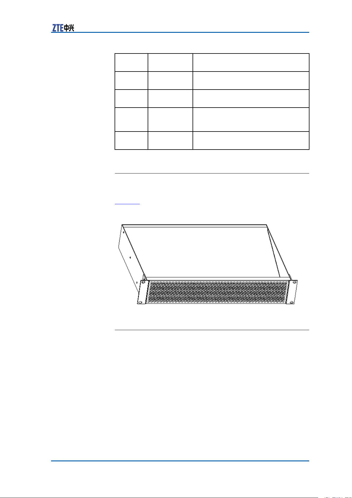
Wind-guidePlate
Thewind-guideplateleadswindowfromfanstocoolmodules.
Figure8illustratesthewind-guideplate.
FIGURE8WIND-GUIDEPLATE
TransmissionSubrack(optional)
Thedimensionofthetransmissionsubrackis50mm(115/26in)
×88mm(37/16in)×300mm(1113/16in)(H×W×D).This
subrackisanoptionalconguration.
CondentialandProprietaryInformationofZTECORPORATION7

ZXSDRBS8800C100HardwareManual
Thispageisintentionallyblank.
8CondentialandProprietaryInformationofZTECORPORATION

Chapter2
Modules
TableofContents
ControlandClockModule(CC)............................................9
ChannelProcessingModule(CH).........................................13
FabricSwitchModule(FS)...................................................17
SiteAlarmModule(SA)......................................................21
FanArrayModule(FA)........................................................27
PowerModule(PM)............................................................28
RadioSystemUnit(RSU)....................................................31
ControlandClockModule (CC)
FunctionCCmoduleprovidesthefollowingfunctions:
�Implementsactive/standbyswitch-overfunction.
�ProvidesGPSsystemclockandRFreferenceclock.
�ProvidesAbisinterfacefunction.
�ProvidesGEEthernetexchangefunctionthroughsingling
streamandmediastreamexchangeplane.
�ProvidesoneUSBinterfaceforpanel.
�Providestheshelfmanagementfunction.
�Providesbasebandmodulationanddemodulationfunction.
�ProvidesthreeremoteberinterfacesandsupportCPRIinter-
faceandsupportRRUasremoteRFinlowcostconguration.
�Providesexternallytheclockextensioninterface(IEEE1588)
andcommunicationextensioninterface(usethelocalmaintenanceinterface).
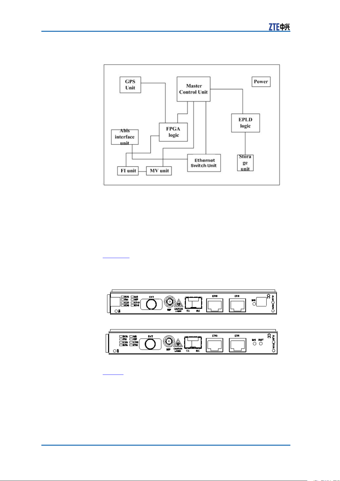
PrincipleFigure9showstheprincipleofCCmodule.
CondentialandProprietaryInformationofZTECORPORATION9
ZXSDRBS8800C100HardwareManual
FIGURE9CCMODULEPRINCIPLE
CCmoduleconsistsofmastercontrolunit,GPSunit,powerunit,
storageunit,Abisinterfaceunit,FIunit,MVunit,Ethernetswitch,
FPGAlogicandEPLDlogic.
MeasurementThedimensionsofCCmoduleinmmare:148.8(H)x19.0(W)x
181.5(D).
ThedimensionsofCCmoduleininchesare:514/16(H)x12/16
(W)x72/16(D)
PanelFigure10showstheappearanceofCCmodulepanelwithandwith-
outhandlerespectively .
FIGURE10CCMODULEPANEL
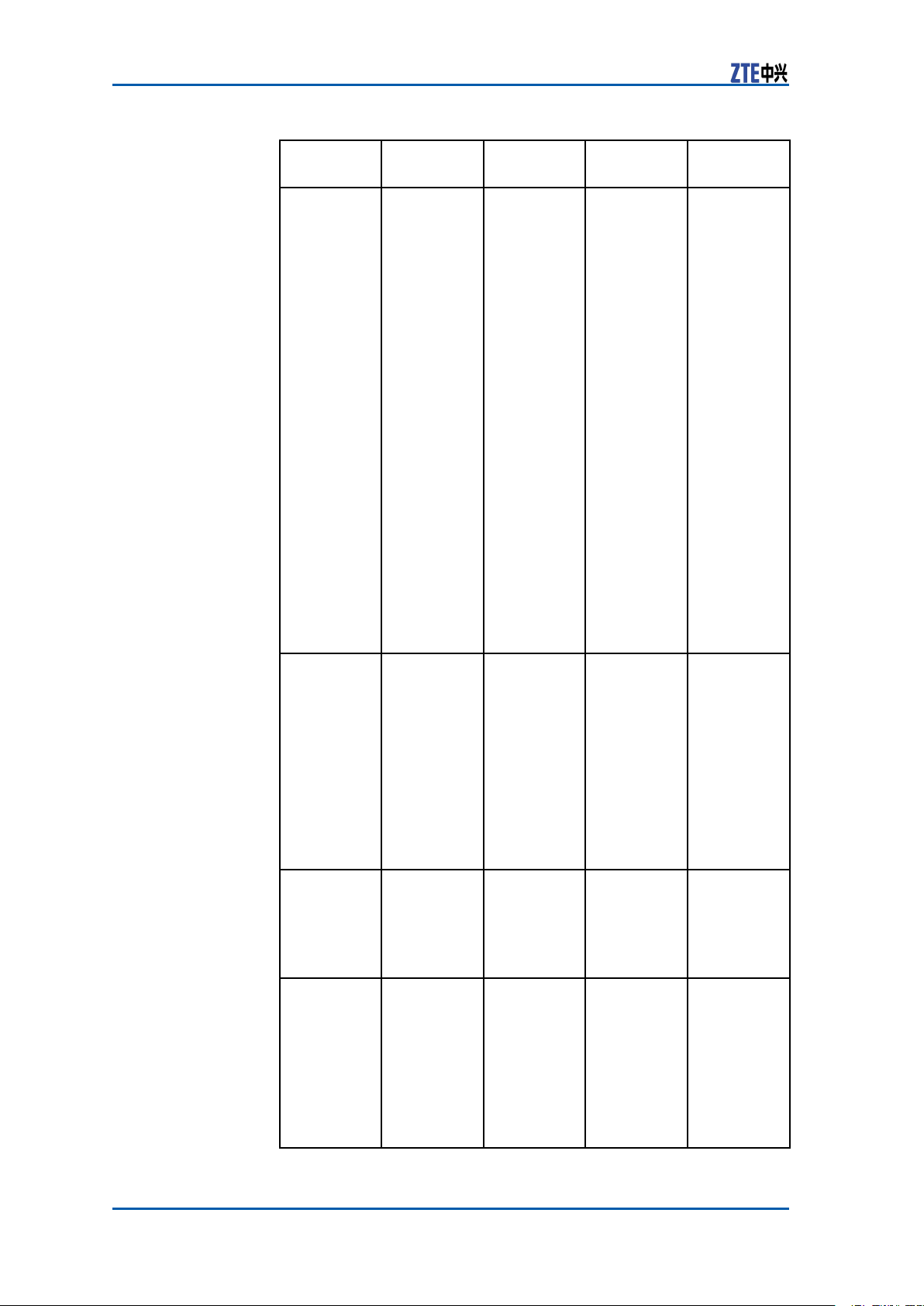
IndicatorT able3describestheindicatorsonthepanelofCCmodule.
10CondentialandProprietaryInformationofZTECORPORATION
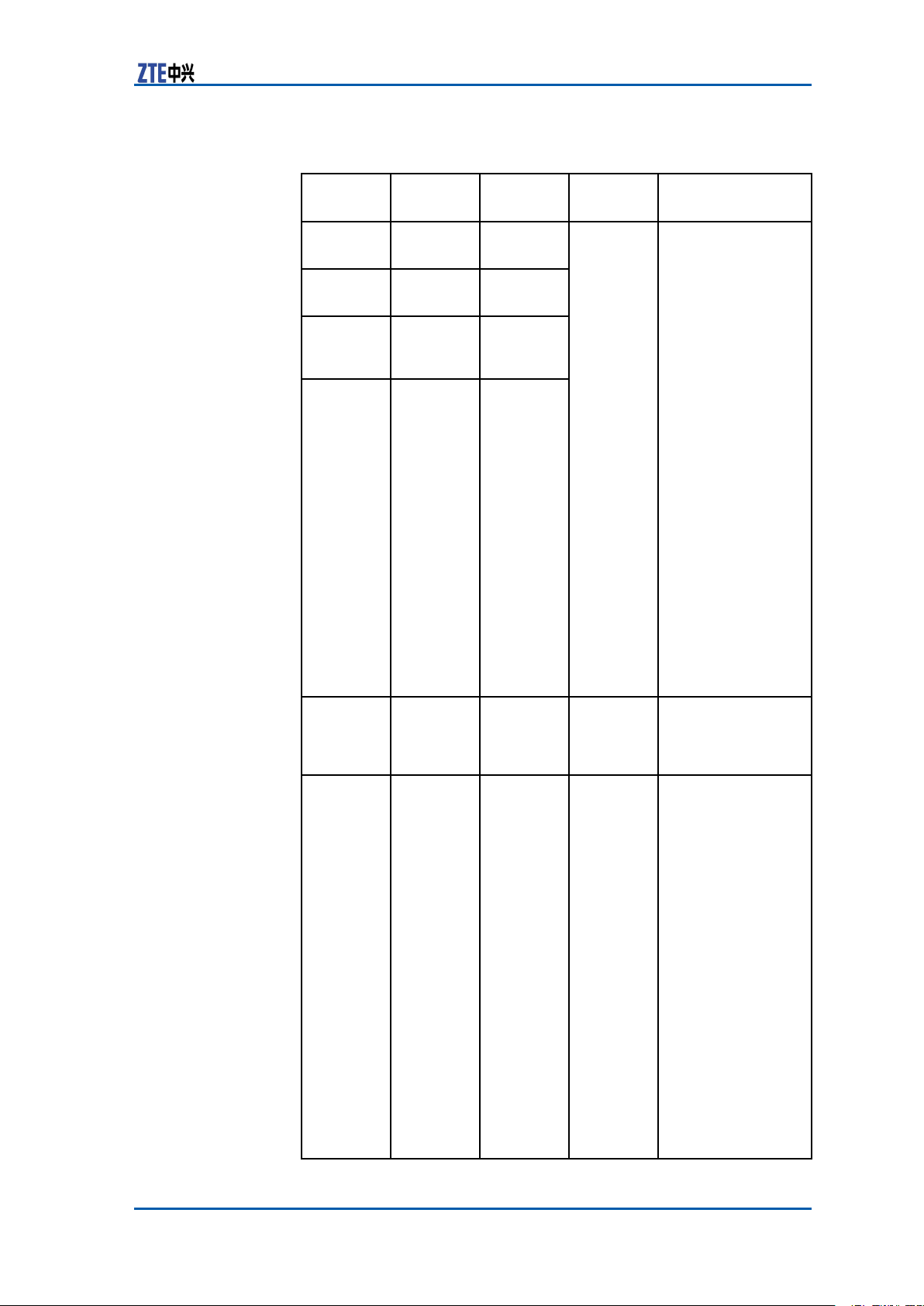
TABLE3CCMODULEPANELINDICATORDESCRIPTION
Chapter2Modules
Indicator
ColorMeaningFlash
Name
E0SGreen
E1SGreen
E2SGreen9-12
E3SGreen13-16
1-4linkE1
indicator
5-8linkE1
indicator
linkE1
indicator
linkE1
indicator
Status
Flashfrequency:
8Hz
Description
Ordinalashon
time,themax4
timespersecond,
0.125sonand
0.125off.
Therstsecond:
oneashmeans
the0linkisnormal
andOffmeansthe
linkbroken.
Thethirdsecond:
twoashesmean
therstlinkis
normalandOff
meansthelink
broken.
Thefthsecond:
threeashesmean
thesecondlink
isnormalandOff
meansthelink
broken.
Theseventh
second:four
ashesmeanthe
thirdlinkisnormal
andOffmeansthe
linkbroken.
Recycleagainfor8
seconds.
MSGreen
REF
GreenGPS
Active/standby
indicator
antenna
indicator
Noash
Onmeansthemain
board
Offmeansthe
standbyboard.
Sixash
types
On:theantenna
feederisnormal
Off:theantenna
feederandthe
satelliteare
initializing
Slowash:the
antennafeederis
broken,1.5sonand
1.5soff
Quickash:the
antennafeederis
normalbutcannot
searchthesatellite,
0.3sonand0.3soff
Slowerash:the
antennaisshort
circuit,2.5sonand
2.5soff
Quickerash:
initializationcan
notreceivethe
message,70mon
and70msoff.
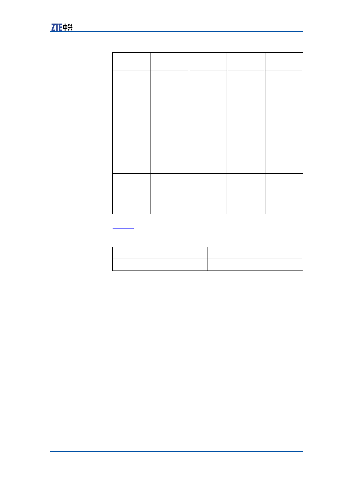
CondentialandProprietaryInformationofZTECORPORATION11
ZXSDRBS8800C100HardwareManual
Indicator
Name
ETH0Green
ETH1
ALM
RUN
ColorMeaningFlash
Abis
interface
linkstatus
indicator
Green
ETH1
network
portlink
status
indicator
RedAlarm
Indicator
Green
Running
Indicator
Status
Description
Noash,
controlled
byPHY
On:theAbis
interfaceis
connected
Off:theAbis
interfaceis
disconnected.
Noash,
controlled
byPHY
On:theETH1
networkportis
connected
Off:theETH1
networkportis
disconnected.
Processor
Control
On:theboardhas
alarm.
Off:theboardhas
noalarm.
Sixash
types
On:theversion
lebeginstorun,
requestingthe
logicaladdressof
theboard.
Slowash(1.5son,
1.5soff)theboard
isinpower-up
procedure.
Normalash(0.3s
on,0.3soff):the
boardisunder
normaloperation
Slowash(2son,
2soff):Theboard
isinactive/standby
pre-changeover
Slowash1son,1s
off:Theboardis
inactive/standby
changeover
Fastash70ms
on,70msoff:
Communication
betweenCC
boardandOMP
isinterrupted,
communication
betweenCC/FS
activeandstandby
isinterrupted,
Communication
betweenCHand
CCisinterrupted,
Communication
betweenFSandCC
isinterrupted.
ButtonT able4describesthebuttonsonthepanelofCCmodule.
12CondentialandProprietaryInformationofZTECORPORATION
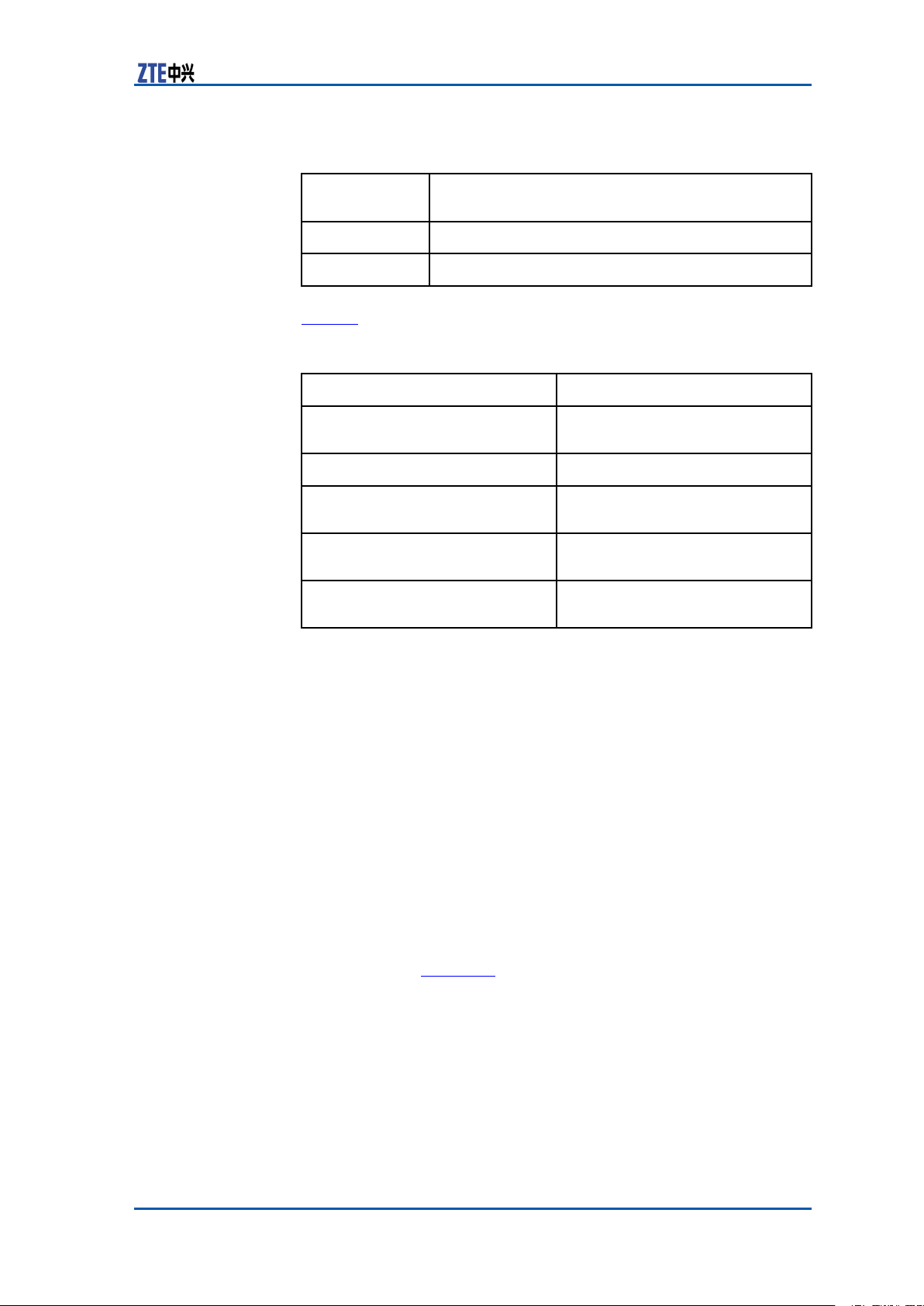
TABLE4CCMODULEPANELBUTTONDESCRIPTION
Chapter2Modules
Printed
ButtonName
M/SMaster/Slavechange-overbutton
RST
PanelInterfaceT able5describesinterfacesonthepanelofCCmodule.
TABLE5CCMODULEPANELINTERFACEDESCRIPTION
InterfaceName
ETH0
ETH1
EXT
REF
TX/RX
ActualFunctionalDescription
Resetbutton
Description
GE/FEportconnectionbetween
BBUandBSC
Debuggingorlocalmaintenance
Connectingtheexternalreceiver
(RS485,PP1Sand2Minterfaces)
ConnectingGPSantenna
externally
Connectingtheopticalinterface
betweenBBUandBSC
ChannelProcessingModule (CH)
FunctionCHmoduleperformsthefollowingfunctions:
�Theforwardmodulationandreversedemodulationofbase-
band
�CDMAkeytechnologies,suchasdiversitytechnique,RAKE
receiving,softer-handoffandpowercontrol
�MixedinsertionofCHV
EV-DOservice.
PrincipleCHVmoduleconsistsofprocessingunit,basebandmodulationand
demodulationunit,FPGAunit,EPLDlogicunit,power ,Ethernetunit
andMMC
unit.Figure11showstheprincipleofCHVmodule.
andCHDmodulestosupport1xand
CondentialandProprietaryInformationofZTECORPORATION13
ZXSDRBS8800C100HardwareManual
FIGURE11CHVMODULEPRINCIPLE
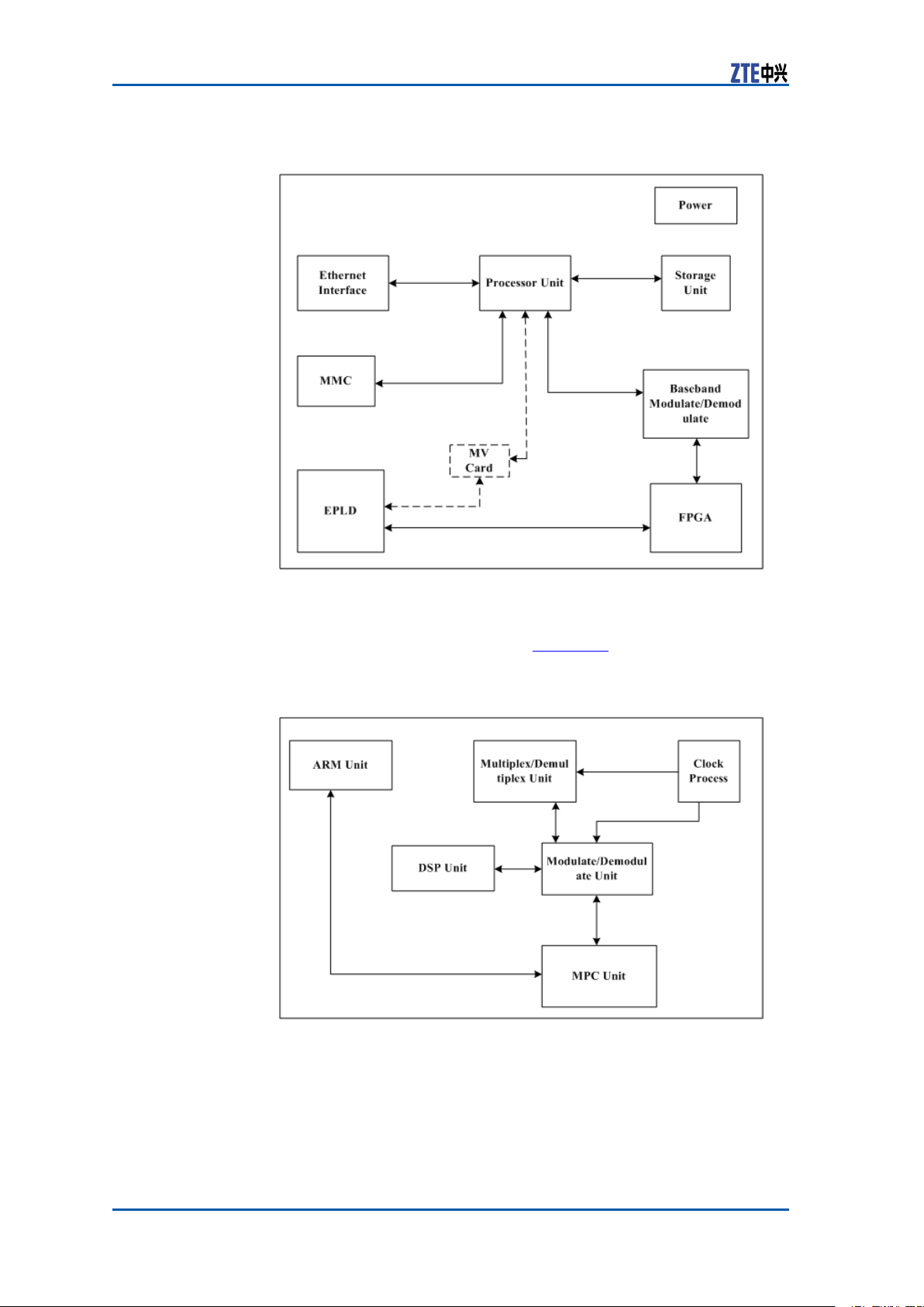
CHDmoduleconsistsofmultiplexingandde-multiplexingunit,
clockprocessingunit,ARMunit,DSPunit,modulationanddemodulationunitandMPCunit.Figure12showstheprincipleof
CHDmodule.
FIGURE12CHDMODULEPRINCIPLE
MeasurementThedimensionsofCHmoduleinmmare:148.8(H)x19.0(W)x
181.5(D).
ThedimensionsofCHmoduleininchesare:514/16(H)x12/16
(W)x72/16(D).
14CondentialandProprietaryInformationofZTECORPORATION
Chapter2Modules
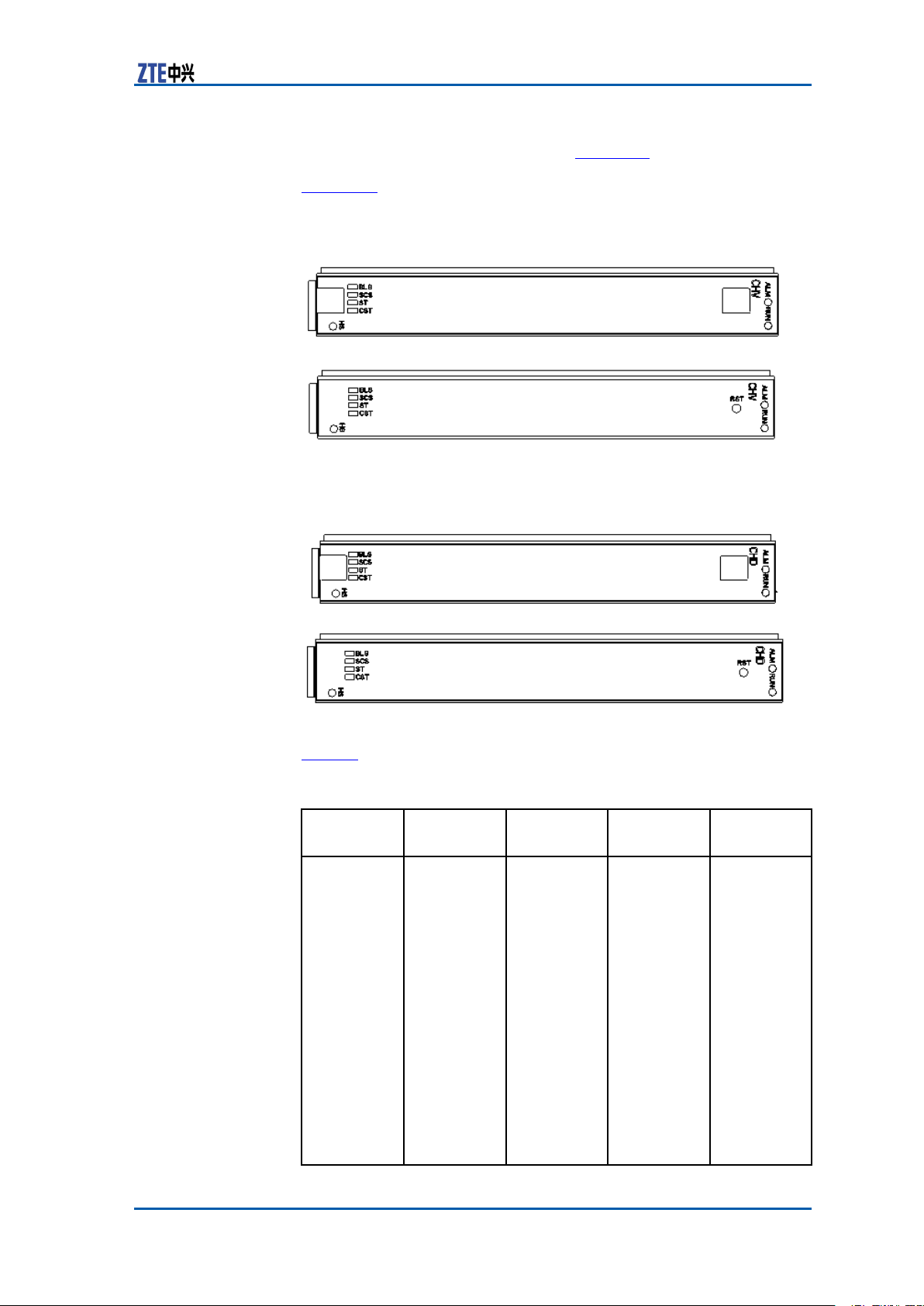
PanelCHisclassiedintoCHVandCHD.Figure13showsthepanelap-
pearanceofCHVmodulewithandwithouthandlerespectively .
Figure14showsthepanelappearanceofCHDmodulewithand
withouthandlerespectively .
FIGURE13CHVMODULEPANEL
FIGURE14CHDMODULEPANEL
IndicatorT able6describestheindicatorsonthepanelofCHmodule.
TABLE6CHMODULEPANELINDICATORDESCRIPTION
Indicator
Name
BLSGreen
ColorMeaningFlash
Baseband
link(forward/reverse)runningstatus
indicator
Status
Theash
frequency
is8Hz;it
indicates
theSERDES
receiving
statusand
theforward
baseband
signal
failurewhile
FS0/FS1
board
connectsto
CHboard.
Description
Ordinal
ashon
time,the
maximum
ashfor
fourtimes
persecond,
0.125sOn
and0.125s
Off
Therst
second:one
ashmeans
communicationwith
FS0isnormalandOff
meanscommunication
CondentialandProprietaryInformationofZTECORPORATION15
ZXSDRBS8800C100HardwareManual
Indicator
Name
ColorMeaningFlash
Status
tion
Descrip-
isbroken.
Theforth
second:
twoashes
meancommunication
withFS1is
normaland
Offmeans
communicationisbroken.
Recycle
againper
6seconds.
IftheforwardIOsignalcheck
fromthe
channelchip
outputis
wrong,itis
alwaysoff.
Ifthe
61.44M
clockor
the32CHIP
clockis
wrong,itis
alwaysoff.
SCSGreenSystem
STGreen
CSTGreenCommuni-
clock
(50CHIP/10ms)
running
status
indicator
Reservation
cationstatusindicatorbetween
CPUand
MMC
Three
statuses:
On,quick
ashand
Off.
Controlled
byCPU,
EPLDtransparent
transmissionmode
Controlled
byCPU,
EPLDtransparent
transmissionmode
On:the
system
clock
runningis
normal.
Quick
ash:10ms
wrong,
0.125sOn
and0.125s
Off.
Off:50CHIP
wrong.
-
On:normal
communicationbetweenCPU
andMMC
Off:failed
communicationbetweenCPU
andMMC.
16CondentialandProprietaryInformationofZTECORPORATION
Chapter2Modules
Indicator
Name
RUN
ALM
ButtonT able7describesthebuttonontheCHPanel.
ColorMeaningFlash
Green
RedAlarm
Running
Indicator
Indicator
Status
Four
statuses:
5Hzash,
1Hzash,
OnandOff.
Processor
Control
Description
5Hzash:
theboardis
inpower-up
procedure.
1Hzash:
theboard
isnormally
running.
On:the
versionis
downloaded
successfully
andisbeing
started.
Off:the
boardis
abnormal.
On:the
boardhas
alarm.
Off:the
boardhas
noalarm.
TABLE7CHBUTTONDESCRIPTION
ButtonName
RST
Description
Reset
FabricSwitchModule(FS)
FunctionsFSmoduleprovidesthefollowingfunctions:
�Inforwarddirection,performsthebasebanddatamultiplexing
andframingandthentransmitthemtotheremoteRRU.
�Inreversedirection,performsde-framingandde-multiplexing
forreceivedRRUremotedata,andthentransmitthemtothe
basebandprocessingunit.
�Supportssixremotebasebandberinterfaces.
�Exceptopticalinterfaceprocessing,otherfunctionsareper-
formedbythelogicunit.
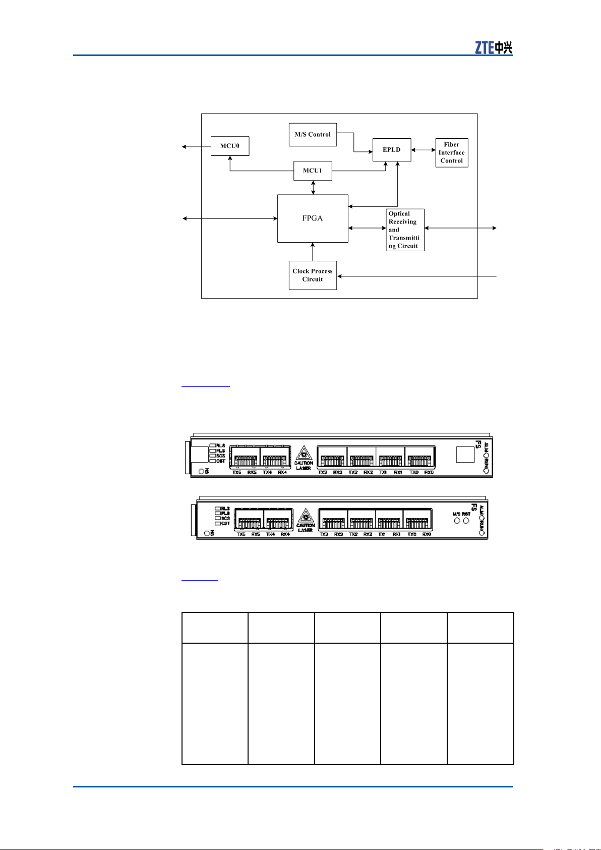
PrincipleFSmoduleconsistsofmaster/slavecontrolunit,MCU0unit,MCU1
unit,EPLDlogic,opticalinterfacecontrolunit,FPGAunit,optical
receivingandtransmittingcircuitandclockprocessingcircuitas
showninFigure15.
CondentialandProprietaryInformationofZTECORPORATION17
ZXSDRBS8800C100HardwareManual
FIGURE15FSMODULEPRINCIPLE
MeasurementThedimensionsofFSmoduleinmmare:148.8(H)x19.0(W)x
181.5(D).
ThedimensionsofFSmoduleininchesare:514/16(H)x12/16
(W)x72/16(D).
PanelFigure16showsthepanelofFSmodulewithandwithouthandle
respectively.
FIGURE16FSMODULEPANEL
IndicatorT able8describestheindicatorsonFSpanel.
TABLE8FSPANELINDICATORDESCRIPTION
Indicator
Name
RLSGreen
ColorMeaningFlash
Reverse
baseband
linkrunning
status
indicator
Status
Controlled
byFPGA;
theash
frequency
is8Hz;
itmeans
thelocking
statusof
thereverse
optical
interfaces
Description
Ordinal
ashon
time,the
maximum
fourashes
persecond,
0.125son
and0.125s
off.
Therst
second:one
18CondentialandProprietaryInformationofZTECORPORATION
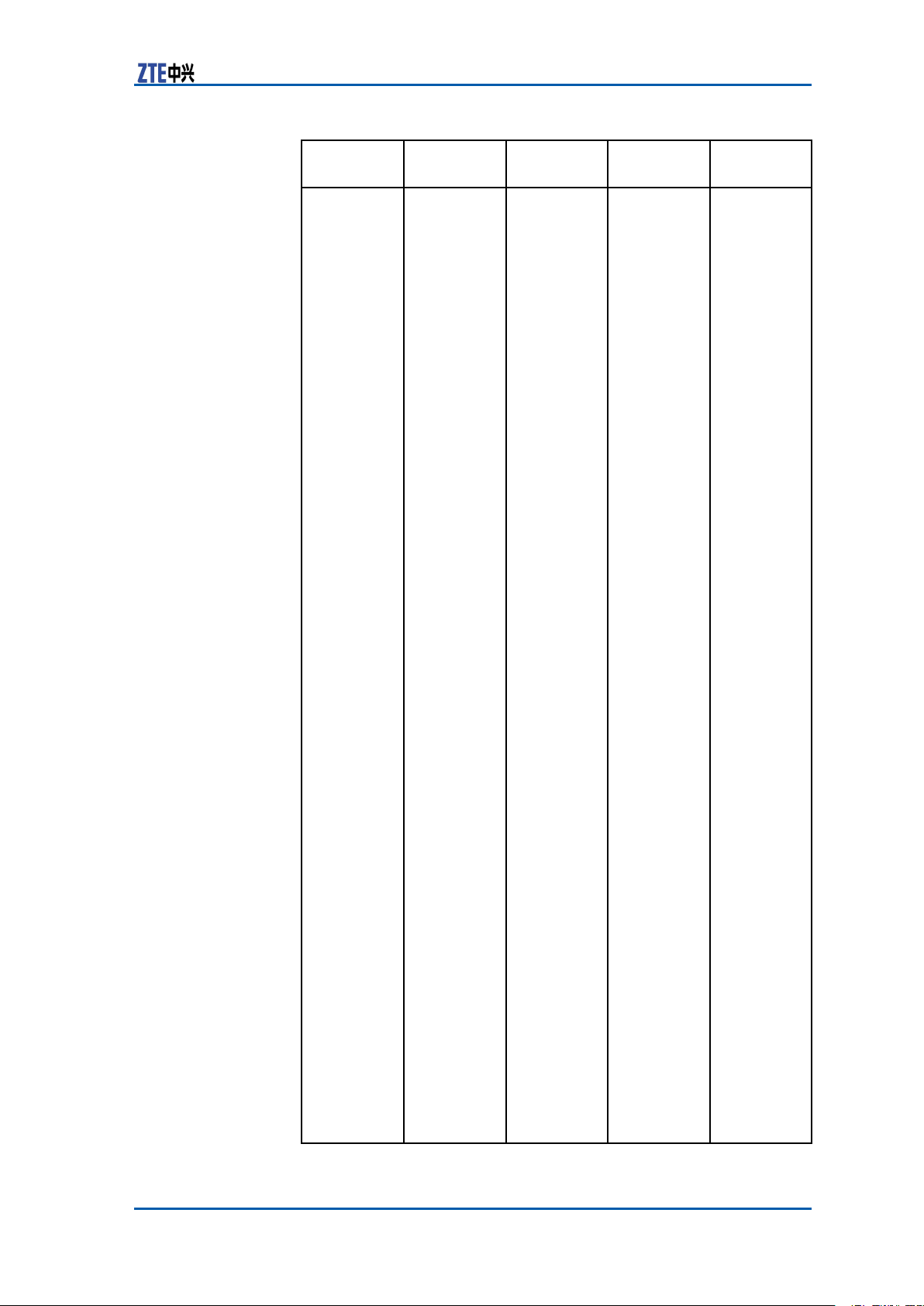
Chapter2Modules
Indicator
Name
ColorMeaningFlash
Status
fromall
berstoFS.
Description
ashmeans
the0linkis
normaland
Offmeans
the0linkis
broken.
Theforth
second:
twoashes
meanthe
1stlinkis
normaland
Offmeans
the1linkis
broken.
Theseventh
second:
three
ashes
meanthe
2ndlinkis
normaland
Offmeans
the2ndlink
isbroken.
Thetenth
second:
fourashes
meanthe
3rdis
normaland
Offmeans
the3rdis
broken.
The
thirteenth
second:
veashes
meanthe
4thlinkis
normaland
Offmeans
the4this
broken.
The
sixteenth
second:
sixashes
meanthe
5thlinkis
normaland
Offmeans
the5this
broken.
Recycle
againper
18seconds.
(Ifthe61.
44Mclickis
wrong,the
indicatoris
alwaysoff)
CondentialandProprietaryInformationofZTECORPORATION19
 Loading...