

Zte ZXSDR BS8800 Technical Manual

ZTE CORPORATION
ZTE Plaza, Keji Road South,
Hi-Tech Industrial Park,
Nanshan District, Shenzhen,
P. R. China
518057
Tel: (86) 755 26771900
Fax: (86) 755 26770801
URL: http://ensupport.zte.com.cn
E-mail: support@zte.com.cn
CDMA
ZXSDR
BS8800
Indoor Basestation-8800
Technical Manual

LEGAL INFORMATION
Copyright © 2006 ZTE CORPORATION.
The contents of this document are protected by copyright laws and international treaties. Any reproduction or distribution of
this document or any portion of this document, in any form by any means, without the prior written consent of ZTE CORPORATION is prohibited. Additionally, the contents of this document are protected by contractual confidentiality obligations.
All company, brand and product names are trade or service marks, or registered trade or service marks, of ZTE CORPORATION
or of their respective owners.
This document is provided “as is”, and all express, implied, or statutory
claimed, including without limitation any implied warranty of merchantability, fitness for a particular purpose, title or non-infringement. ZTE
information contained herein.
ZTE CORPORATION or its licensors may have current or pending intellectual property rights or applications covering the subject
matter of this document. Except as expressly provided in any written license between ZTE CORPORATION and its licensee,
the user of this document shall not acquire any license to the subject matter herein.
ZTE CORPORATION reserves the right to upgrade or make technical change to this product without further notice.
Users may visit ZTE technical support website http://ensupport.zte.com.cn to inquire related information.
The ultimate right to interpret this product resides in ZTE CORPORATION.
CORPORATION and
its licensors shall not be liable for damages resulting from the use of or reliance on the
warranties, representations
or conditions are dis-
Revision History
Revision No. Revision Date Revision Reason
R1.0
Serial Number: sjzl20090166
01/30/2009 First Edition

Contents
Preface ...............................................................
Product
Position in the
Product
Product
Product Services............................................................. 5
Product Features
External Interfaces
Application
Product
Standard
Working
System Architecture.......................................................15
Signal
Power Distribution .........................................................19
Ventilation and Heat-dissipation Principles......................... 21
Networking and
Abis Interface Networking...............................................25
Baseband-RF Interface Networking ..................................26
Cabinet Configuration..................................................... 27
Board
Equipment Management
OMC
LMT Mode..................................................................... 34
Technical Indices
Engineering Indices ....................................................... 35
Performance Indices ......................................................35
Clock Parameters...........................................................36
Overview ..............................................
Network....................................................
Appearance ........................................................
Functions ...........................................................
............................................................
.........................................................
Scenarios
Reliability
Compliance
.....................................................10
..........................................................10
.....................................................12
Principle ............................................
Flow
................................................................... 16
Service Signal
Control Signal
Clock Signal Flow ......................................................18
Flow
....................................................16
Flow
....................................................18
Configuration.........................
Configuration
....................................................... 30
Modes .......................
Mode
.................................................................... 33
............................................
i
1
1
2
3
5
6
15
25
33
35

RF Indices .................................................................... 36
Interfaces and Protocols
Network Reference Model ...............................................41
Um Interface ................................................................42
Abis Interface ............................................................... 47
Common Public Radio Interface
................................
(CPRI)
............................. 48
Figures ............................................................
Tables
List of
.............................................................
Glossary................................................
41
51
53
55

Purpose This manual provides the product overview of ZXSDR BS8800
Prerequisite Skill
Intended
Audience
and Knowledge
What is in
Manual
This
Preface
, which will help readers to know its functions, features, protocol
interfaces, working principles, technical indices and standard
compliance.
This document is intended for engineers and technicians who perform operation activities ZXSDR BS8800 .
To use this document effectively, users should have a general understanding of ZXSDR BS8800 equipment and its compo- nents.
Familiarity with the following is helpful:
�
cdma2000 fundamental
�
ZXSDR BS8800 hardware structure
This manual contains the following chapters:
Chapter
Chapter 1 Product
Overview
Chapter 2 Working
Principle
Chapter 3
Networking and
Configuration
Chapter 4
Equipment
Management Modes
Chapter 5 Technical
Indices
Chapter 6 Interfaces
and Protocols
Confidential and Proprietary Information of ZTE CORPORATION i
Summary
Describes the appearance, functions, features,
interfaces, application scenarios and standard
compliance of the product.
Describes the system architecture, signal flows,
power distribution and the ventilation and
heat-dissipation principles of the product.
Describes the networking modes of each
NE interface and the product configuration
principles.
Describes the equipment maintenance and
management modes.
Describes the technical indices of the
product, including dimension, weight,
temperature, humidity, capacity, interface,
power consumption, RF and clock parameters.
Describes the product interfaces and protocols.

ZXSDR BS8800 Technical Manual
ii Confidential and Proprietary Information of ZTE CORPORATION
This page is intentionally blank.
C
h a p t e r
1
Product Overview
Table of Contents
Position in the Network
Product
Product
Product
Product Features
External Interfaces
Application
Product
Standard
Appearance ............................................................
Functions ...............................................................
Services.................................................................
................................................................
Scenarios
Reliability
Compliance
.......................................................
.............................................................
.........................................................10
.............................................................. 10
.........................................................12
1
2
3
5
5
6
Position
in the Network
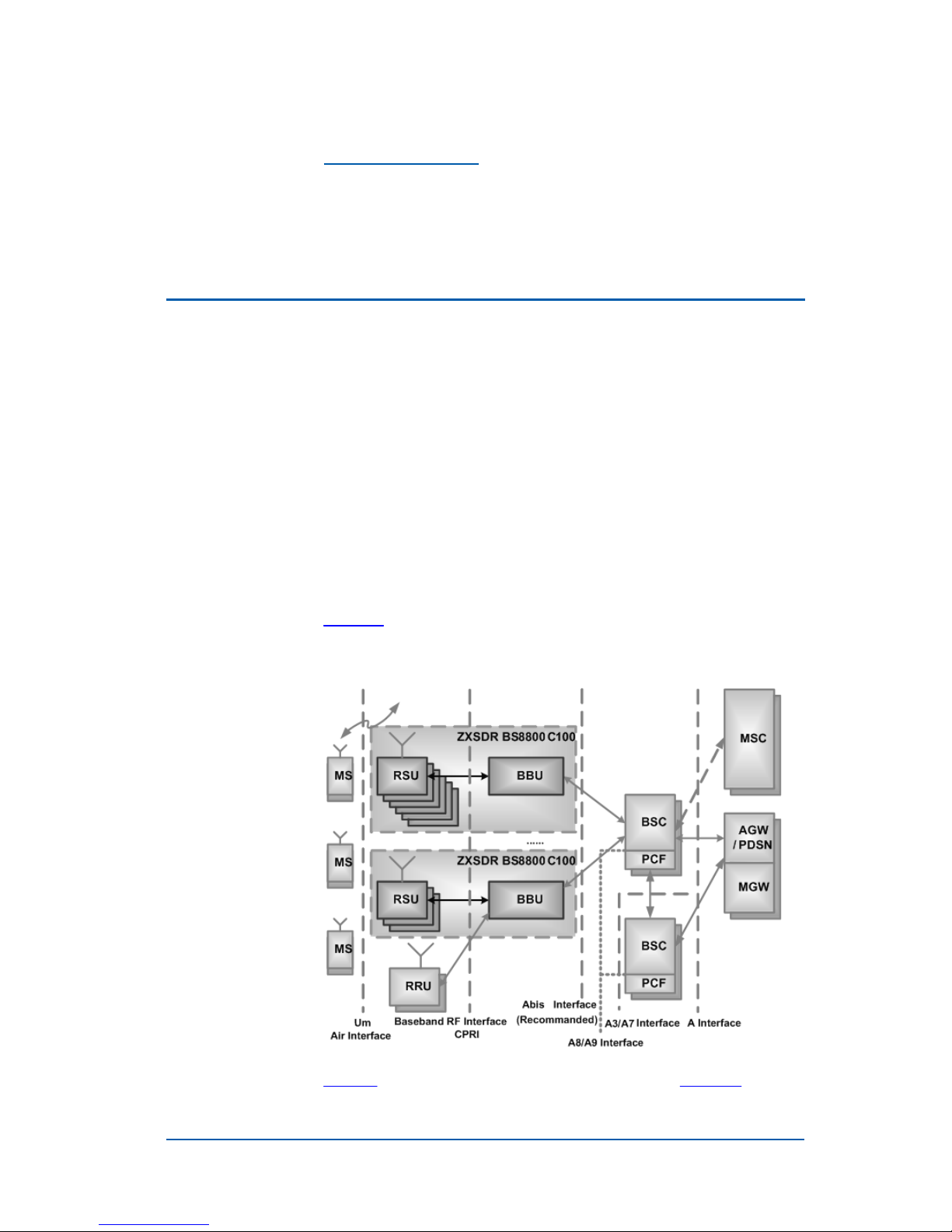
Figure 1 illustrates the position of ZXSDR BS8800 in a typical
CDMA mobile communication network.
F
IGURE
1 ZXSDR BS8800 P
OSITION IN
CDMA
N
ETWORK
Table 1 lists the description of NE terms used in Figure 1.
Confidential and Proprietary Information of ZTE CORPORATION 1

ZXSDR BS8800 Technical Manual
T
ABLE
1 NE T
ERMS DESCRIPTI ON
NE-Short Form
MS
RRU
RSU
BBU
BSC
PCF
MSC
AGW
PDSN
MGW
NE-Expanded Form
Mobile Station
Remote Radio Unit
RF System Unit
BaseBand Unit
Base Station Controller
Packet Control Function
Mobile Switching Center
ASN GateWay
Packet Data Service Node
Media GateWay
ZXSDR BS8800 locates between BSC and MS to fulfill three
functions of BTS:
�
Communication with MS through Um interface
�
Communication with BSC through Abis interface
�
Control over radio channels
Product
Appearance
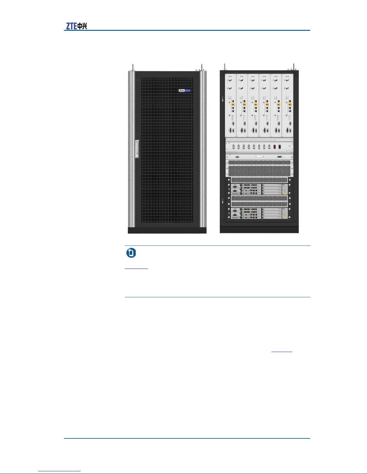
Figure 2 shows the appearance of ZXSDR BS8800 .
2 Confidential and Proprietary Information of ZTE CORPORATION
F
IGURE
2 ZXSDR BS8800 A
PPEARANCE
Chapter 1 Product
(-48V
P
OWER SUPPLY
Overview
)
Note:
Figure 2 shows the appearance of the ZXSDR BS8800 adopt- ing
—48V DC power supply. The ZXSDR BS8800 adopting
+24V DC power supply contains an extra 1–U PSU subrack and
a different power distribution subrack. Its appearance diagram is
omitted here.
Product
Functions
ZXSDR BS8800 product functions are listed inTable 2.
Confidential and Proprietary Information of ZTE CORPORATION 3

ZXSDR BS8800 Technical Manual
T
ABLE
Category
2 ZXSDR BS8800 P
Description
RODUCT FUNCTIONS
Baseband
RF
Interface
Supports baseband sharing (12 sectors as a unit) and IO
crossing
Supports GPS timing and synchronization
Single BBU provides 1x or DO channel resource up to 36
sectors.
Each RSU and BBU does separate configuration of mains
switch and protection.
Supports 2 BBUs at most, be they work singly or together
RF modulation/demodulation
Supports 6 RSUs and multi-band configuration
Set-top output power of 60 W (800 MHz band)
Provides the maximum RF capacity of 36 carrier sectors
Supports arbitrary configuration of 6 carriers within the
20 MHz band in case of single RF link.
Supports electrical antenna
Baseband-RF interface supports CPRI interface.
Abis interface supports IP Over Ethernet Access and IP
Over TDM Access.
RF part restores synchronization clock through
baseband-RF interface, supports delay measurement and
implements delay compensation.
Networking
Environment
Monitoring
Supports star and chain networkings of outgoing RRU
Supports up to 6 cascade networking of outgoing RRU
Provides outgoing RS232/RS485 monitor communication
interface
Supports over/under voltage alarm of input power supply
Supports cabinet door open inhibition, temperature and
flooding alarms
Supports equipment entrance inhibition, humidity,
temperature, infrared and smog alarms
4 Confidential and Proprietary Information of ZTE CORPORATION

Chapter 1 Product
Overview
Category
Maintenance
Test
Product
Description
Supports remote version upgrade of such software as
FPGA/BOOT/DSP/CPU
Supports ESN query function
Supports LOMC function
Supports remote resetting and power-off of service boards
Supports against-wall installation and front maintenance
Provides integrated alarm detection and report mechanism
Services
Table 3 lists the services provided by ZXSDR BS8800 .
T
ABLE
3 ZXSDR BS8800 P
Service
1x
1x Low Speed
Data Service
Voice Service
Description
N/A
Data rate up to 307.2 kbit/s
RODUCT SERVICES
DO High Speed
Data Service
Product
Peak forward data rate is 3.1 Mbit/s
Peak reverse data rate is 1.8 Mbit/s
Features
ZXSDR BS8800 product features are listed as follows:
�
Indoor integrated base station that adopts 19–inch standard
cabinet with a compact structure
�
Supporting multiple frequency bands
�
High maintainability and reliability
�
High capacity and integration to save network establishment
and capacity expansion expenses
�
Modular design, flexible configuration, high compatibility and
expansibility
�
Wall mount installation, external cable lead in from cabinet top,
front maintenance
�
Supporting -48V/+24V DC power
� Flexible
modes.
�
Separation of Baseband and RF to enable evolution and up-
grade
networking. It
Confidential and Proprietary Information of ZTE CORPORATION 5
supports
either star or chain networking
ZXSDR BS8800 Technical Manual
External
Interfaces
RF Subrack
External
Interfaces
ZXSDR BS8800 external interfaces locate in RF subrack, fan
subrack, —48V/+24V power distribution subrack, PSU subrack
(equipped during the adoption of +24V DC power supply) and
baseband subrack.
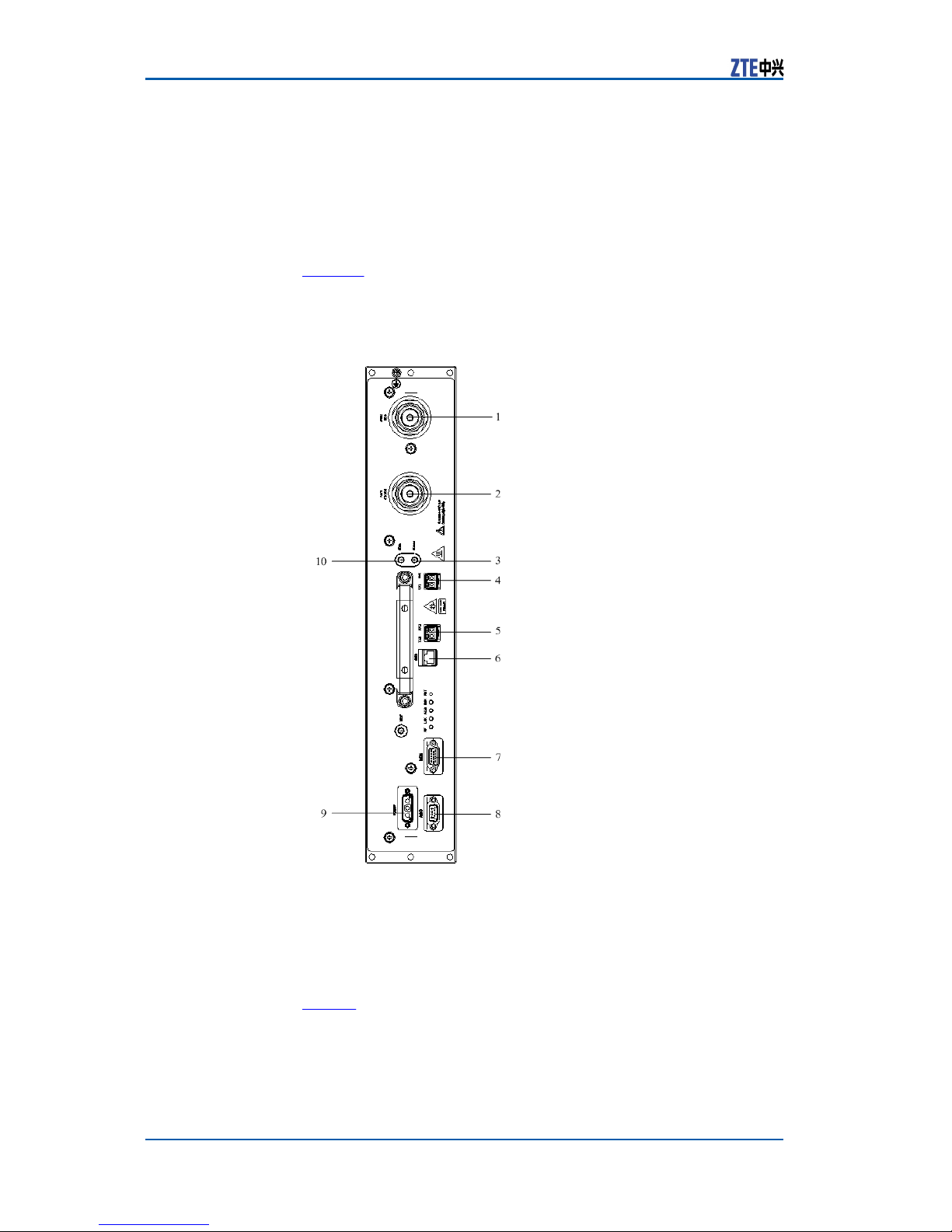
Figure 3 shows RF subrack external interfaces on the RSU panel.
F
IGURE
3 RF S
UBRACK EXTERNAL INTERFACES
1. ANT2(RX)
2. ANT1(TX/RX)
3. RXout
4. TX1 RX1
5. TX2 RX2
Table 4 lists the description of RF subrack external interfaces.
6 Confidential and Proprietary Information of ZTE CORPORATION
6. DBG
7. MON
8. AISG
9. POWER
10. RXin
Chapter 1 Product
Overview
T
ABLE
4 RF S
UBRACK EXTERNAL INTERFACE DESCRIPTION
Interface
ANT1(TX/RX
ANT2(RX)
RXout
TX1 RX1
TX2 RX2
DBG
MON
AISG
Description
Completes connection to the
antenna of main transmitting
and receiving channels
Completes connection to
antenna of diversity receiving
channel
Frequency extension output
interface to
received signals
CPRI optical interface to connect
BBU or the superior RSU
CPRI optical interface to connect
the subordinate cascaded RSU
Completes network interface
debugging and interface test
Provides dry contact input
interface and RS485
environment monitoring
interface
Completes the
antenna feeder AISG interface
the
output
main
connection to
Module Located
RSU
RSU
RSU
RSU
RSU
RSU
RSU
RSU
POWER
RXin
DC power input interface
Frequency extension input
interface to input diversity
received
signals
RSU
RSU
Fan Subrack
External
Interfaces
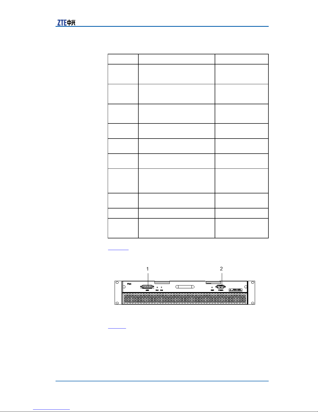
Figure 4 shows the external interfaces on the fan subrack panel.
F
IGURE
4 F
AN SUBRACK EXTERNAL INTERFACES
1. MON 2. POWER
Table 5 lists the description of fan subrack external interfaces.
Confidential and Proprietary Information of ZTE CORPORATION 7
ZXSDR BS8800 Technical Manual
T
ABLE
5 F
AN SUBRACK EXTERNAL INTERFACE DESCRIPTION
Subrack
—48V Power
Distribution
External
Interfaces
Interface
MON
POWER
Description
Fan monitoring interface
Power input interface of the fan
subrack
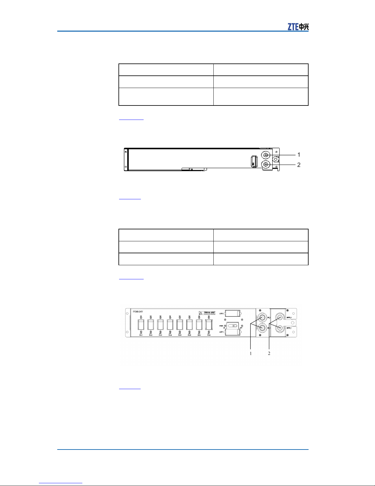
Figure 5 shows the external interfaces on the panel of the —48V
power distribution subrack.
F
IGURE
5 -48V P
OWER DISTRIBUTION SUBRACK EXTERNAL INTERFACES
1. -48 V 2. -48 V RTN
Table 6 lists the description of —48V power distribution subrack
external interfaces.
T
ABLE
6 —48V P
D
ESCRIPTION
Interface
-48 V
OWER DISTRIBUTION SUBRACK EXTERNAL INTERFACE
Description
-48 V DC input terminal
-48 V RTN
+24V Power
Distribution
Subrack
Interfaces
External
Figure 6 shows the external interfaces on the panel of the +24V
power distribution subrack.
F
IGURE
6 +24V P
OWER DISTRIBUTION SUBRACK EXTERNAL INTERFAC ES
1. 24V_1/2 2. 24VRTN_1/2
Table 7 describes the external interfaces of the +24V power dis-
tribution subrack.
8 Confidential and Proprietary Information of ZTE CORPORATION
-48 V DC grounding terminal
Chapter 1 Product
Overview
T
ABLE
7 +24V P
D
ESCRIPTI ON
OWER DISTRIBUTION SUBRACK EXTERNAL INTERFACE
PSU Subrack
External
Interfaces
Interface
24V_1/2
24VRTN_1/2
Description
+24 V DC input terminal
+24 V DC grounding terminal
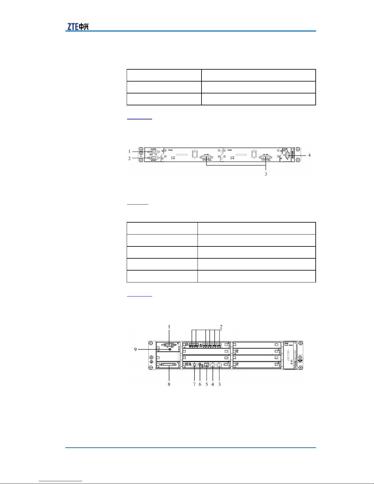
Figure 7 shows the external interfaces on the panel of the PSU
subrack.
F
IGURE
7 PSU S
UBRACK EXTERNAL INTERFACES
1. –48V OUTPUT1
2. –48V OUTPUT2
3. 24V INPUT
4. MON
Table 8 describes the external interfaces of the PSU subrack.
T
ABLE
8 PSU S
Interface
–48V OUTPUT1
–48V OUTPUT2
UBRACK EXTERNAL INTERFACE DESCRIPTION
Description
–48V DC output interface 1
–48V DC output interface 2
Subrack
Baseband
External
Interfaces
24V INPUT
MON
+24V DC input interface
PSU subrack fan monitoring interface
Figure 8 shows the external interfaces on the baseband subrack
panel.
F
IGURE
8 B
ASEBAND SUBRACK EXTERNAL INTERFACES
1. -48V -48V RTN
2. TX0~5 RX0~5
3. ETH1
4. ETH0
5. TX RX
6. REF
7. EXT
Confidential and Proprietary Information of ZTE CORPORATION 9
8. MON/Abis
9. MON

ZXSDR BS8800 Technical Manual
Table 9 lists the description of baseband subrack external inter-
faces.
T
ABLE
9 B
ASEBAND SUBRACK EXTERNAL INTERFACES DESCRIPTI ON
Interface
-48V -48VRTN
TX0~5 RX0~5
ETH1
ETH0
TX RX
REF
EXT
MON/Abis
MON
Description
-48 V DC power input interface
Baseband-RF optical interface
Used for BS commissioning or
local maintenance
Electrical interface to connect
BSC
Optical interface to
Connects external GPS antenna
Connects external receiver
Includes Abis, RS232, RS485 and
dry contact
RS232 interface for power
module
debugging
connect BSC
Module
Located
PM
FS
CC
CC
CC
CC
CC
SA
PM
Application
Scenarios
ZXSDR BS8800 is an integrated base station with single cab- inet
for indoor application.
ZXSDR BS8800 attaches great importance to the project
demand and the flexibility of base station construction. The indoor macro cell, in particular, takes up less room, supports wall
mount installation, adopts forward routing technology and completes subrack plugged out maintenance in front of the cabinet.
ZXSDR BS8800 is applicable for the equipment room with less
space available.
ZXSDR BS8800 is low in cost and high in capacity and expansibility. It integrates built-in transmission equipment and supports
IP over Ethernet and IP over TDM transmission.
Product
Hardware
Reliability
10 Confidential and Proprietary Information of ZTE CORPORATION
Hardware reliability lies mainly in the following items.
1. Module repower-on function
Reliability
In case of invalid module software reset, implement power-off
reset to the module power supply through CC. CC controls over
CH, FS and SA, other modules being unaffected.

Chapter 1 Product
Overview
Software
Reliability
2. Module in-position detection function
CC communicates with each module to judge the normality of
their operation, and implements in-position detection of CH,
PS and SA modules via backplane or connection of Baseband
part for higher reliability.
3. Module reverse insertion prevention function
if it is inserted upside down, the module fails to contact the
backplane normally so as to protect the equipment from damage.
4. Power over-voltage, over-current and inverse connection protection function
5. Backup strategy
�
CC module supports the operation mode of 1+1 master
slave hot backup.
�
BBU adopts the concept of resource pool. Baseband mod-
ule conducts load sharing.
�
FS module supports load sharing.
6. Quality attribute design
�
Loose coupling in system design of RF, baseband and con-
trolling parts in view of their separation to prevent cross
interference
�
-48V distributed power supply with lightning proof design
�
Failure remote location, a better mode for field hard fault
and graceful failure.
�
Reliable grounding design
�
Consideration of structure, hot design and overall wiring
�
Simplification and error protection design
Software reliability lies mainly in the following items.
1. Software operation support reliability
�
Collects periodical statistics of task CPU occupancy and
heap.
�
Monitors abnormal status such as system CPU overload,
task endless loop, suspension and dead lock.
�
Captures various CPU abnormality and processes accord-
ingly.
�
Provides reset log and black box and records the field infor-
mation when board software failure happens for the convenience of failure location.
2. Database management reliability
�
Provides abnormality report mechanism and notifies the
user of detailed failure reason when configuring base station with OMC software.
�
Checks the
consistency
of NE and OMC data via overall configuration, data uploading and data increment synchronization.
�
Master slave hot backup to keep consistent data via overall
data synchronization and increment synchronization.
Confidential and Proprietary Information of ZTE CORPORATION 11

ZXSDR BS8800 Technical Manual
3. Link transmission reliability
�
Provides data saving protection mechanism via file mapping, log and memory to ensure the data complement and
consistency in case of emergency such as power off.
�
Provides abnormal log record function and NE/OMC configuration track record function for the convenience of failure
location.
�
Active and standby link changeover to increase link reliability
�
Transmission layer adopts reliable transmission protocol to
prevent distributed denial attack.
�
Network layer conducts multiplexing of IP resource and
routing table via VRF and supports transmission via IP default gateway in case of route search failure.
�
Link layer adopts Vlan to isolate broadcast.
�
Protocol stack provides received packet processing protection function.
�
Separates operation maintenance and service processing
with IPinIP protocol bearer OMC channel.
Standard
Compliance
�
International
Standards
12 Confidential and Proprietary Information of ZTE CORPORATION
TIA/EIA/IS-127Enhanced Variable Rate Codec Speech Service
Option 3 for Wideband Spread Spectrum Digital Systems1996
�
TIA/EIA/IS-634AMSC-BS Interface for Public Communications
Networks
� TIA/EIA/IS-637
Spectrum Cellular
� TIA/EIA/IS-658
1998
Short Message Service for Wideband Spread
Systems
Data Service Interworking Function Interface
for Wideband Spread Spectrum Systems
�
TIA/EIA/IS-707 Data Service Options for Wideband Spread
Spectrum
�
TIA/EIA/IS-725 Over-the-Air Service Provisioning of Mobile
Systems
1998
Stations in Wideband Spread Spectrum Systems1997
�
TIA/EIA/IS-728 Inter-System Link Protocol
�
TIA/EIA/IS-733High Rate Speech Service Option 17 for Wide-
band Spread Spectrum Communication Systems
�
TIA/EIA/IS-97 Recommended Minimum Performance Stan-
dards for Base Stations Supporting Dual-Mode Wideband
Spread Spectrum Cellular Mobile Stations1996
� TIA/EIA/IS-99
Data Services Option Standard for Wideband
Spread Spectrum Digital Cellular System1995
� TIA/EIA/TSB-58
Administration Parameter Value Assignments
for TIA/EIA Wideband Spread Spectrum Standards1995
1995

Chapter 1 Product
Overview
�
TIA/EIA/TSB-74Support for 14.4 Kbps Data Rate and PCS In-
teraction for Wideband Spread Spectrum Cellular System1995
�
3GPP2 C.S0002-A Introduction to cdma2000 Standards for
Spread Spectrum Systems
�
3GPP2 C.S0003-A Physical Layer Standard for cdma2000
Spread Spectrum Systems
�
3GPP2
C.S0004-A
Medium Access Control (MAC) Standard for
cdma2000 Spread Spectrum Systems
�
3GPP2
C.S0005-ASignaling
Link
Access Control
(LAC) Standard
for cdma2000 Spread Spectrum Systems
�
3GPP2 C.S0006-AUpper Layer (Layer 3) Signaling Standard for
cdma2000 Spread Spectrum Systems
�
ANSI
J-STD-008
Personal Station-Base Station Compatibility
Requirement for 1.8 to 2.0 GHz Code Division Multiple Access
(CDMA) Personal Communications System1996
�
CDG
IOS4.2
MSC to BS Interface Inter-operability Specifica-
tion Sprint
�
CDG
IOS5.0
MSC to BS Interface Inter-operability Specifica-
tion Sprint
�
CDG
RF36
Markov Service Option for Wideband Spread Spec-
trum Communications Sytems
�
ITU Recommendation Z.100Specification and Description Lan-
guage
�
ITU Recommendation Z.120 Message Sequence Charts
(MSC)
�
ITU-T M.3010Principles for a Telecommunications Management
Network
�
ITU-T M.3020TMN Interface Specification Methodology1995
�
ITU-T M.3100Generic Network Information Model1995
�
ITU-T M.3200TMN Management Services and Telecommunica-
tion Managed
�
ITU-T
(SDL)
1992
1996
M.3300
1994
Areas Overview
1997
TMN Management Capability Presented at the F
Interface 1992
�
ITU-T M.3400TMN Management Function 1997
�
ITU-T
Q.811
Lower Layer Protocol Profiles for the Q3 and X
Interface 1997
�
ITU-T
Q.812
Upper Layer Protocol Profiles for the Q3 and X
Interface 1997
�
ITU-T Q.821Stage 2 and Stage 3 Description for the Q3 Inter-
face – Alarm
�
ITU-T
Q.822
Surveillance
1993
Stage 1 Stage 2 and Stage 3 Description for the
Q3 Interface – Performance Management1994
�
ITU-T X.700Management Framework for Open Systems Inter-
connection (OSI) for CCITT Application1992
�
ITU-T X.710Common Management Information Service Defini-
tion for CCITT
Applications
1991
Confidential and Proprietary Information of ZTE CORPORATION 13
 Loading...