

ZTE ZXR10W800A Users Manual

ZXR10 WAS (V2.0) IP Wireless
Access System
W800A Wireless Access Point
User’s Manual
ZTE CORPORATION

ZXR10 WAS (V2.0) IP Wireless Access System
W800A Wireless Access Point
User’s Manual
Manual Version 20040306-R1.0
Product Version V2.0
BOM ЧЧЧЧЧЧЧЧ
Copyright © 2003 ZTE Corporation
All rights reserved.
No part of this documentation may be excerpted, reproduced, translated, annotated or
duplicated, in any form or by any means without the prior written permission of ZTE
Corporation.
ZTE CORPORATION
ZTE Plaza, Keji Road South, Hi-Tech Industrial Park, Nanshan District, Shenzhen, P. R. China
Website: http://www.zte.com.cn
Post code: 518057
Customer Support Center: (+86755) 26770800 800-830-1118
Fax: (+86755) 26770801
E-mail: 800@zte.com.cn
* * * *
S.N.: DDDDDDDDD

FAX: +86-755-26770160
Suggestions and Feedback
To improve the quality of ZTE product documentation and offer better services to our customers, we hope
you can give us your suggestions and comments on our documentation and fax this form to
0086-755-26770160; or mail to “ZTE Plaza, Keji Road South, Hi-Tech Industrial Park, Nanshan District,
Shenzhen, P. R. China”. Our postcode is 518057.
Document Name ZXR10 WAS (V2.0) IP Wireless Access System W800A Wireless Access Point User’s Manual
Product version V2.0 Document version 20040306-R1.0
Equipment installation time
Your information
Name Company
Postcode Company address
Telephone E-mail
Good Fair Average Poor Bad
Overall
Instructiveness
Your evaluation
of this
documentation
Your suggestion
on the
improvement of
this
documentation
Your other
suggestions on
ZTE product
documentation
Index
Correctness
Completeness
Structure
Illustration
Readability
Overall
Instructiveness
Index
Correctness
Completeness
Structure
Illustration
Readability


Preface
About This Manual
This manual, ZXR10 WAS (V2.0) IP Wireless Access System W800A Wireless Access
Point — User’s Manual, is applicable to W800A wireless access point (W800A for
short) of the ZXR10 WAS (V2.0) IP wireless access system.
The ZXR10 WAS IP wireless access system is the IP wireless access system developed
by ZTE. It consists of a series of wireless access network products, such as wireless
network card, wireless access point (AP) and DSL 2-in-1 wireless router.
Serving as the operation guide to W800A, this manual introduces the function features,
installation, operation, using and maintenance of W800A. This manual consists of 7
chapters and 2 appendixes.
Chapter 1, Safety Precautions, introduces the safety precautions of this product and
safety symbols used in this manual.
Chapter 2, Overview, presents functions, features and technical parameters of W800A.
Chapter 3, Structure and Principle , describes structure and principle of W800A.
Chapter 4, Installation and Debugging, deals with the installation and debugging
methods of W800A.
Chapter 5, Command Line Configuration, covers the command line configurations of
W800A.
Chapter 6, WEB Configuration, examines WEB configurations of W800A.
Chapter 7, Maintenance, puts forward the daily maintenance and version upgrade
methods of W800A.
Appendix A, Packing, Transportation and Storage, outlines the packaging method,
storage conditions and transpor tation precautions of W800A.
Appendix B, Making of Ethernet cables, details the power supply mode of W800A
Ethernet and making of Ethernet cables.

Conventions
Four striking symbols are used throughout this manual to emphasize important and
critical information during operation:
Attention, Caution, Warning and Danger: alerting
you to pay attention to something.
Statement: The actual product may differ from what is described in this
manual due to frequent update of ZTE products and fast development of
technologies. Please contact the local ZTE office for the latest updating
information of the product.

Contents
1 Safety Precautions................................................................................................................... 1-1
1.1 Safety Precautions ............................................................................................................ 1-1
1.2 Symbol Description........................................................................................................... 1-2
2 Overview................................................................................................................................ 2-1
2.1 Preface............................................................................................................................ 2-1
2.2 Functions and Features ...................................................................................................... 2-1
2.3 Technical Characteristics and Parameters............................................................................. 2-3
3 Structure and Principle ........................................................................................................... 3-1
3.1 Structure and Working Principle ......................................................................................... 3-1
3.2 Units/Components ............................................................................................................ 3-2
3.2.1 Front Panel............................................................................................................... 3-2
3.2.2 Rear Control Panel .................................................................................................... 3-3
3.3 Networking Modes ........................................................................................................... 3-4
3.3.1 AP Mode Application ................................................................................................ 3-5
3.3.2 Bridge Connection Mode Application.......................................................................... 3-6
3.3.3 Wireless Repeater Mode Application ........................................................................... 3-7
4 Installation and Debugging...................................................................................................... 4-1
4.1 Installation Preparations .................................................................................................... 4-1
4.1.1 Installation Preparation Flow...................................................................................... 4-1
4.1.2 Tool, Instrument and Document .................................................................................. 4-4
4.1.3 Installation Environment Inspection ............................................................................ 4-4
4.1.4 Unpacking Inspection ................................................................................................ 4-4
4.2 Installation....................................................................................................................... 4-4
-i-

-
4.3 Power-on and Power -off.....................................................................................................4-5
4.4 Debugging........................................................................................................................ 4-6
5 Command Line Configuration................................................................................................. 5-1
5.1 Overview ......................................................................................................................... 5-1
5.2 User Mode ....................................................................................................................... 5-4
5.2.1 Entering the Privileged Mode...................................................................................... 5-4
5.2.2 Exiting the Telnet Configuration ..................................................................................5-4
5.3 Privileged Mode ................................................................................................................5-5
5.3.1 Network Connectivity Check ......................................................................................5-5
5.3.2 Saving the Configuration Data to FLASH..................................................................... 5-5
5.3.3 Restoring the Default Configuration .............................................................................5-5
5.3.4 Resetting the Software ...............................................................................................5-6
5.3.5 Entering the Configure Mode ......................................................................................5-6
5.3.6 Exiting the Privileged Mode ....................................................................................... 5-6
5.3.7 Exiting the Telnet Configuration.................................................................................. 5-6
5.4 Configure Mode ................................................................................................................5-6
5.4.1 Bridge Configuration ................................................................................................. 5-7
5.4.2 Clearing the Information ............................................................................................ 5-7
5.4.3 Configuring the Configuration Server .......................................................................... 5-8
5.4.4 DHCP Server Configuration ....................................................................................... 5-8
5.4.5 DISCOVER Configuration .......................................................................................5-10
5.4.6 802.1X Parameter Configuration ............................................................................... 5-11
5.4.7 Password Configuration in the Privileged Mode..........................................................5-14
5.4.8 Erasing the Filtration Rules .......................................................................................5-14
5.4.9 Exiting the Configure Mode ......................................................................................5-14
5.4.10 IAPP Load Balance Configuration ...........................................................................5-15
-ii

5.4.11 Entering the Interface Configuration Mode................................................................5-16
5.4.12 IP Network Parameter Configuration ........................................................................5-17
5.4.13 Kicking Users ........................................................................................................5-18
5.4.14 Two -Layer Separation Configuration........................................................................5-18
5.4.15 Log Printing Message Configuration .........................................................................5-19
5.4.16 MAC Filtration Configuration ..................................................................................5-20
5.4.17 MAC Address Authentication Configuration..............................................................5-21
5.4.18 Manager Configuration...........................................................................................5-21
5.4.19 QoS Configuration .................................................................................................5-22
5.4.20 RADIUS Server Configuration ................................................................................5-22
5.4.21 SNMP Module Configuration ..................................................................................5-24
5.4.22 SSH Parameter Configuration..................................................................................5-28
5.4.23 Spanning Tree Parameter Configuration....................................................................5-29
5.4.24 TELNET Configuration ..........................................................................................5-32
5.4.25 Uploading/Downloading TFTP Files .........................................................................5-32
5.4.26 VLAN Configuration..............................................................................................5-33
5.4.27 Web Configuration .................................................................................................5-34
5.4.28 Nation Zone Configuration......................................................................................5-34
5.4.29 Showing Parameter Configuration............................................................................5-35
5.5 Ethernet Interface Configuration Mode...............................................................................5-41
5.5.1 Exiting the Ethernet Interface Configuration Mode .......................................................5-42
5.5.2 Ethernet Interface MAC Filtration Configuration .........................................................5-42
5.6 Wireless Interface Configuration Mode ...............................................................................5-42
5.6.1 802.11 -Related Parameter Configuration of the Wireless Interface..................................5-42
5.6.2 ESSID Hiding Configuration.....................................................................................5-45
5.6.3 Exiting the Wireless Interface Configuration Mode ......................................................5-46
-iii-

5.6.4 Enabling the Link Integrity Detection Function...........................................................5-46
5.6.5 Wireless Interface MAC Filtration Configuration .........................................................5-46
5.6.6 Multi-ESSID Configuration ......................................................................................5-46
5.6.7 Security Parameter Configuration..............................................................................5-47
5.6.8 Transmission Power Configuration ............................................................................5-49
5.6.9 Working Mode Configuration ....................................................................................5-49
6 WEB Configuration................................................................................................................. 6-1
6.1 Overview ......................................................................................................................... 6-1
6.2 Login............................................................................................................................... 6-3
6.3 Main Menu .......................................................................................................................6-4
6.3.1 Home....................................................................................................................... 6-4
6.3.2 Interface ...................................................................................................................6-5
6.3.3 Stations.................................................................................................................... 6-9
6.3.4 Load Balance ..........................................................................................................6-10
6.3.5 SNMP.................................................................................................................... 6-11
6.3.6 Security..................................................................................................................6-15
6.3.7 Reboot ...................................................................................................................6-19
6.3.8 Save ......................................................................................................................6-20
6.3.9 Advanced...............................................................................................................6-20
6.3.10 Management.........................................................................................................6-29
6.4 Data Submitting Flow of WEB Configuration .....................................................................6-32
7 Maintenance ............................................................................................................................7-1
7.1 Maintenance Descriptions .................................................................................................. 7-1
7.2 Daily Maintenance............................................................................................................ 7-2
7.3 Version Loading and Upgrade ............................................................................................. 7-2
7.3.1 BOOT Loading ......................................................................................................... 7-2
-iv-

7.3.2 TFTP Online Loading............................................................................................... 7-11
7.4 Alarms and Handling ........................................................................................................7-13
Appendix A Package, Transportation and Storage.......................................................................A-1
A.1 Package.......................................................................................................................... A-1
A.2 Transportation ................................................................................................................. A-1
A.3 Storage........................................................................................................................... A-1
Appendix B Making of Ethernet Cable ....................................................................................... B-1
B.1 W800A System Application Modes ....................................................................................B -1
B.2 Making of Ethernet Cables ................................................................................................B -3
B.2.1 Making of Straight Through Ethernet Cables (RJ45) .....................................................B-3
B.2.2 Making of Straight Through Power Supply Ethernet Cables (C-RJ45-001).......................B -3
B.2.3 Making of Crossover Ethernet Cables (RJ45J).............................................................B -4
B.2.4 Ethernet Cable Label................................................................................................B -5
-v-


A List of Figures
Fig. 3.1-1 W800A Appearance............................................................................................... 3-1
Fig. 3.2-1 Schematic Diagram of the Rear Control Panel of W800A ........................................... 3-3
Fig. 3.3-1 Application of the W800A Single Frequency Mode ................................................... 3-5
Fig. 3.3-2 Application of the W800A Double Frequency Mode .................................................. 3-6
Fig. 3.3-3 Wireless Bridge Connection Mode .......................................................................... 3-7
Fig. 3.3-4 Wireless Repeater Mode......................................................................................... 3-8
Fig. 4.1-1 Sub-Channel Distribution....................................................................................... 4-2
Fig. 4.1-2 Channel Distribution Principle of Adjacent APs ........................................................ 4-3
Fig. 5.1-1 Serial Port Configuration ........................................................................................5-3
Fig. 5.1-2 Telnet to W800A................................................................................................... 5-3
Fig. 6.1-1 Route Map of the WEB Configuration ..................................................................... 6-2
Fig. 6.2-1 Login Page ........................................................................................................... 6-3
Fig. 6.2-2 Dialog Box for a User Who Has Logged on .............................................................. 6-3
Fig. 6.2-3 Prompt Page for Wrong User Name or Password....................................................... 6-4
Fig. 6.3-1 Home Page........................................................................................................... 6-4
Fig. 6.3-2 Interface Configuration Menu Page ......................................................................... 6-5
Fig. 6.3-3 Wireless Interface Configuration Menu Page ............................................................ 6-6
Fig. 6.3-4 802.11 Parameter Configuration Page ...................................................................... 6-6
Fig. 6.3-5 Security Configuration Page ................................................................................... 6-7
Fig. 6.3-6 Multi- ESSID Configuration Page ............................................................................ 6-8
Fig. 6.3-7 Advanced Configuration Page .................................................................................6-8
Fig. 6.3-8 Device IP Address Configuration Page..................................................................... 6-9
Fig. 6.3-9 Stations Page .......................................................................................................6-10
-i-

Fig. 6.3-10 Load Balance Configuration Page ........................................................................ 6-11
Fig. 6.3-11 SNMP Configuration Menu Page ......................................................................... 6-11
Fig. 6.3-12 SNMP Access Mode Configuration Page...............................................................6-12
Fig. 6.3-13 SNMP Access Host Configuration Page ................................................................ 6-12
Fig. 6.3-14 Community Configuration Page ...........................................................................6-13
Fig. 6.3-15 System Information Page ....................................................................................6-14
Fig. 6.3-16 Trap Configuration Page .....................................................................................6-15
Fig. 6.3-17 Trap Host Configuration Page..............................................................................6-15
Fig. 6.3-18 Security Configuration Menu Page .......................................................................6-16
Fig. 6.3-19 MAC Authentication Configuration Page ..............................................................6-16
Fig. 6.3-20 MAC Filter Configuration Page ...........................................................................6-17
Fig. 6.3-21 Stations Isolation Configuration Page ...................................................................6-18
Fig. 6.3-22 SSH Configuration Page .....................................................................................6-18
Fig. 6.3-23 Reboot Page......................................................................................................6-19
Fig. 6.3-24 Page of Inputting the Privileged Password.............................................................6-19
Fig. 6.3-25 Page of Closing the Window ................................................................................6-20
Fig. 6.3-26 Save Page .........................................................................................................6-20
Fig. 6.3-27 Advanced Option Configuration Menu Page ..........................................................6-21
Fig. 6.3-28 802.1x Configuration Page ..................................................................................6-22
Fig. 6.3-29 DHCP Configuration Menu Page .........................................................................6-22
Fig. 6.3-30 DHCP Server Configuration Page ........................................................................6-23
Fig. 6.3-31 IP Pool Configuration Page .................................................................................6-23
Fig. 6.3-32 RADIUS Server Configuration Menu Page............................................................6-24
Fig. 6.3-33 ISP Configuration Page ....................................................................................... 6-24
Fig. 6.3-34 Authentication Server Configuration Page .............................................................6-25
Fig. 6.3-35 Accounting Server Configuration Page .................................................................6-26
-ii-

Fig. 6.3-36 DNS Server Configuration Page ...........................................................................6-26
Fig. 6.3-37 Bridge Configuration Page ...................................................................................6-27
Fig. 6.3-38 STP Configuration Page ......................................................................................6-28
Fig. 6.3-39 VLAN Configuration Page ..................................................................................6-29
Fig. 6.3-40 QoS Configuration Page ......................................................................................6-29
Fig. 6.3-41 Management Configuration Menu Page .................................................................6-30
Fig. 6.3-42 Management Accounts Configuration Page ............................................................6-30
Fig. 6.3-43 Management Control Page ...................................................................................6-31
Fig. 6.3-44 Configure Server Configuration Page ....................................................................6-31
Fig. 6.4-1 Prompt of Wrong Data Input..................................................................................6-32
Fig. 6.4-2 Prompt Page of Inputting Superuser Password .........................................................6-32
Fig. 6.4-3 Prompt Page of Wrong Superuser Password.............................................................6-33
Fig. 6.4-4 Prompt Page of Successful Data Submission............................................................6-33
Fig. 7.3-1 Serial Port Configuration ........................................................................................7-3
Fig. 7.3-2 Wftpd User Configuration Interface......................................................................... 7-4
Fig. 7.3-3 Interface of Adding a New Wftpd User .................................................................... 7-4
Fig. 7.3-4 TFTP Configuration Interface................................................................................ 7-11
Fig. B.1-1 Common Application Networking Mode of the IP Wireless Access System ..................B-1
Fig. B.1-2 Application of the System with Ethernet Power Supply .............................................B -2
Fig. B.2-1 Label of the Straight Through Ethernet Cable ...........................................................B -5
Fig. B.2-2 Label of the Straight Through Power Supply Ethernet Cable ......................................B -5
Fig. B.2-3 Label of the Crossover Ethernet cable .....................................................................B -6
-iii-


A list of Tables
Table 1.2-1 Safety Symbols and Descriptions .......................................................................... 1-3
Table 2.3-1 W800A Technical Indices..................................................................................... 2-3
Table 3.1-1 Configuration Table of MiniPci Wireless Network Card for W800A .......................... 3-2
Table 3.2-1 Description of Indicators on W800A Panel ............................................................. 3-3
Table 4.1-1 IDs and Frequencies of Channels .......................................................................... 4-2
Table 5.6-1 W800A Working Channels ..................................................................................5-45
Table 7.4-1 Summary of the Alarm Information ........................................................................7-13
Table A.1-1 W800A Packing List ........................................................................................... A-1
Table B.2-1 Connections of Straight Through Ethernet Cables (RJ45).........................................B -3
Table B.2-2 Connections of Straight Through Power Supply Ethernet Cables (C-RJ45-001)..........B -4
Table B.2-3 Connections of Crossover Ethernet Cables (RJ45J) ................................................. B-4
-i-


1 Safety Precautions
This chapter introduces the safety precautions of this product and safety symbols used
in this manual.
1.1 Safety Precautions
This device complies with Part 15 of the FCC Rules. Operation is subject to the
following two conditions: ( 1) This device may not cause harmful interference, and( 2)
this device must accept any interference received, including interference that may
cause undesired operation.
To assure continued compliance, (example – use only shielded interface cables when
connecting to computer or peripheral devices). Any changes or modifications not
expressly approved by the party responsible for compliance could void the user’s
authority to operate the equipment.
NOTE: This equipment has been tested and found to comply with the limits for a Class
B digital device, pursuant to Part 15 of the FCC Rules. These limits are designed to
provide reasonable protection against harmful interference in a residential installation.
This equipment generates, uses and can radiate radio frequency energy and, if not
installed and used in accordance with the instructions, may cause harmful interference
to radio communications. However, there is no guarantee that interference will not
occur in a particular installation. If this equipment does cause harmful interference to
radio or television reception, which can be determined by turning the equipment off
and on, the user is encouraged to try to correct the interference by one of the following
measures:
- Reorient or relocate the receiving antenna.
- Increase the separation between the equipment and receiver.
- Connect the equipment into an outlet on a circuit different from that to which the
receiver is connected.
- Consult the dealer or an experienced radio/TV technician for help.
This equipment is with high temperature and voltage, so only the professional
1-1

ZXR10 WAS (V2.0) IP Wireless Access System W800A Wireless Access Point User’s Manual
personnel who had passed the training can install, operate and maintain it.
ZTE assumes no responsibility for consequences resulting from violation of general
specifications for safety operations or of safety rules for design, production and use of
equipment.
1.2 Symbol Description
See Table 1.2-1 for the safety symbols used in this manual, which serves to remind the
readers of the safety precautions to be taken when the equipment is installed, operated
and maintained.
1-2
Chapter 1 Safety Precautions
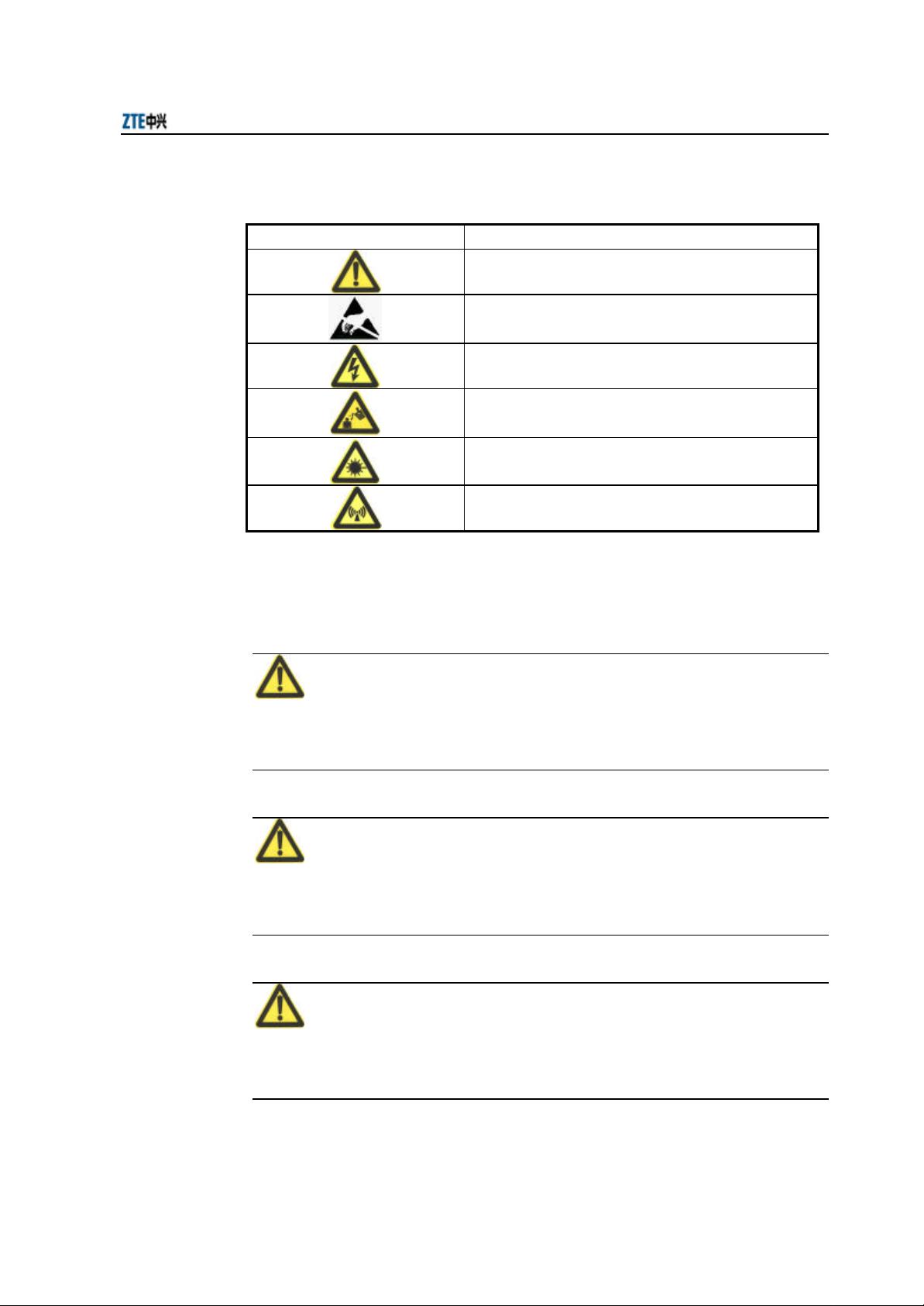
Table 1.2-1 Safety Symbols and Descriptions
Safety Symbols Meaning
Call for notice
Call for antistatic measures
Warn against electric shock
Caution against scald
Warn against laser
Caution against microwave
Four types of safety levels are available: danger, warning, caution and note. To the
right of a safety symbol is the text description of its safety level. Under the symbol is
the detailed description about its contents. See the following formats.
Danger:
Any failure to take the reminder seriously may lead to important accidents, such as
casualties or damage to the equipment.
Cautions:
Any failure to take the reminder seriously may lead to important or severe injury
accidents, or damage to the equipment.
Caution:
Any failure to take the reminder seriously may lead to severe injury accidents or
damage to the equipment.
1-3

ZXR10 WAS (V2.0) IP Wireless Access System W800A Wireless Access Point User’s Manual
Note:
Any failure to take the reminder seriously may lead to injury accidents or damage to
the equipment.
& Remark, reminder, tip…
The remarks, prompt and tips in addition to safety statements.
1-4

2 Overview
This chapter presents functions, features, technical characteristics and parameters of
W800A.
2.1 Preface
W800A is a wireless AP product developed by ZTE and is designed totally compliant
with the international standards. With it, single- AP connection, multi-AP connection
and wireless cellular roaming in large scope are available, greatly improving work
efficiency and living quality.
2.2 Functions and Features
Through UTP (RJ45 interface) cable, the W800A can be connected to Ethernet at
10/100 Mbps to provide wireless access service. Once the wireless network card is
used and required network parameters are configured correctly, a client which is in the
valid coverage range of W800A can be connected to the local LAN through W800A,
and then be connected to Internet.
The function features of the W800A are as follows:
= The maximum access rate is 108 Mbps. At most 100 Stations can be accessed.
= MAC layer bridge connection function: 802.3 frame from Ethernet can be
received and be converted into 802.11 frame, and then be transmitted to the
wireless transceiver; or 802.11 frame from the wireless transceiver can be
received and be converted into 802.3 frames, and then be transmitted to
Ethernet.
= Transparent bridge connection provides packet transfer between Basic Service
Set (BSS) and Distributed System (DS). The maximum transmitting rate is not
less than 20 Mbps.
= The load balance adopts the access balance with multiple APs in the same area
provided by the internal protocol.
2-1

ZXR10 WAS (V2.0) IP Wireless Access System W800A Wireless Access Point User’s Manual
= Static MAC filtration can filter MAC addresses set by users. Up to 99 filtration
groups can be set and each of them can be set with 64 MAC address filtration
rules.
= It provides two configuration modes: WEB and command line, to configure
W800A.
= It provides seamless roaming to enable users to access network easily.
= ESSID provides network authentication to prevent illegal users from accessing
the network.
= High capability of interconnection enables it to interconnect with 10/100 Mbps
Ethernet, comply ing with IEEE 802.3 network convention.
= QoS function, compliant with 802.11e, to implement QoS control based on
SSID and maps QoS into 802.1p at the uplink port.
= VLAN function,W800A can divide VLAN based on SSID,W800A uplink port
supports 802.1q VLAN Trunk.
= It provides SSH information safety function.
= Security, supports 64-bit, 128-bit or 152-bit WEP encryption, 802.1x and
extended Athentication ,and also supports Wi-Fi Protected Access (WPA)
WLAN security standard, TKIP and AES encryption to further protect data
transmission.
= Automatic consistent correction system provides Automatic Scale Back
Functionality (ASBF) to automatically correct WLAN to the best connection
quality.
= It provides integrated management server to monitor and manage ZTE wireless
network equipment, including W800A, in the distributive environment.
= Its configuration server can manage all the APs and download versions through
the configuration server.
= The version upgrade function upgrades the W800A software version,supports
Remote and Local online version loading.
= The embedded SNMP Agent supports SNMP v1/2c to implement MIB II,
IEEE802.11 MIB, IF-MIB, EtherLike-MIB and private MIB.
2-2

2.3 Technical Characteristics and Parameters
The technical indices of W800A are shown in Table 2.3-1.
Table 2.3-1 W800A Technical Indices
Items Technical Indices
Standard 802.11a, 802.11b, 802.11g, 802.1d and 802.3u
802.11a: 5.15GHz~5.25GHz, 5.25GHz~5.35GHz and 5.725~5.825GHz
Working band
Modulation mode
Data rate
Distance (m) Indoor: 20m ~ 100m; outdoor: 100m ~ 300m
External interfaces RJ45 interface, serial interface and wireless interface
Channel quantity
Recommended number
of users/maximum
number of users
MAC address capacity 1024
Encryption type
Dimensions 208mm × 180mm × 47mm (W × L × H)
Weight 1kg (without power supply)
Power supply mode DC 12V power supply and 48V Ethernet power supply
Specification of power
adapter
Working temperature: -5 ºC ~ 45 ºC
Storage temperature -40 ºC ~ 70 ºC
Working humidity 5% ~ 95%
Storage humidity 10% ~ 100%
802.11b: 2400MHz~2483.5MHz
802.11g: 2400MHz~2483.5MHz
Can flexibility chose the frequency band of the different contry
802.11a: OFDM (64-QAM, 16-QAM and QPSK, BPSK)
802.11b: DSSS (DBPSK, DQPSK and CCK)
802.11g: OFDM (64-QAM, 16-QAM, QPSK and BPSK)
802.11a: 6Mbps, 9Mbps, 12Mbps, 18Mbps, 24Mbps, 36Mbps, 48Mbps
and 54Mbps
802.11b: Adaptive 1Mbps, 2Mbps, 5.5Mbps and 11Mbps
802.11g: 6Mbps, 9Mbps, 12Mbps, 18Mbps, 24Mbps, 36Mbps, 48Mbps
and 54Mbps
802.11b: EU: 13; USA and Canada: 11; France: 4; Japan: 14
802.11a: Up to 24 channels are provides according to different national
standards
802.11g: EU: 13; USA and Canada: 11; France: 4
30/100
64/128/152-bit WEP encryption
802.1x Authentication
TKIP & AES encryption
Input: 100VAC~240VAC, 50Hz~60Hz
Output: 12VDC, 1.2A
2-3
Chapter 2 Overview

ZXR10 WAS (V2.0) IP Wireless Access System W800A Wireless Access Point User’s Manual
2-4
3 Structure and Principle
This chapter introduces W800A structure and principle: hardware structure, working
principle, interfaces, indicators and networking mode.
3.1 Structure and Working Principle
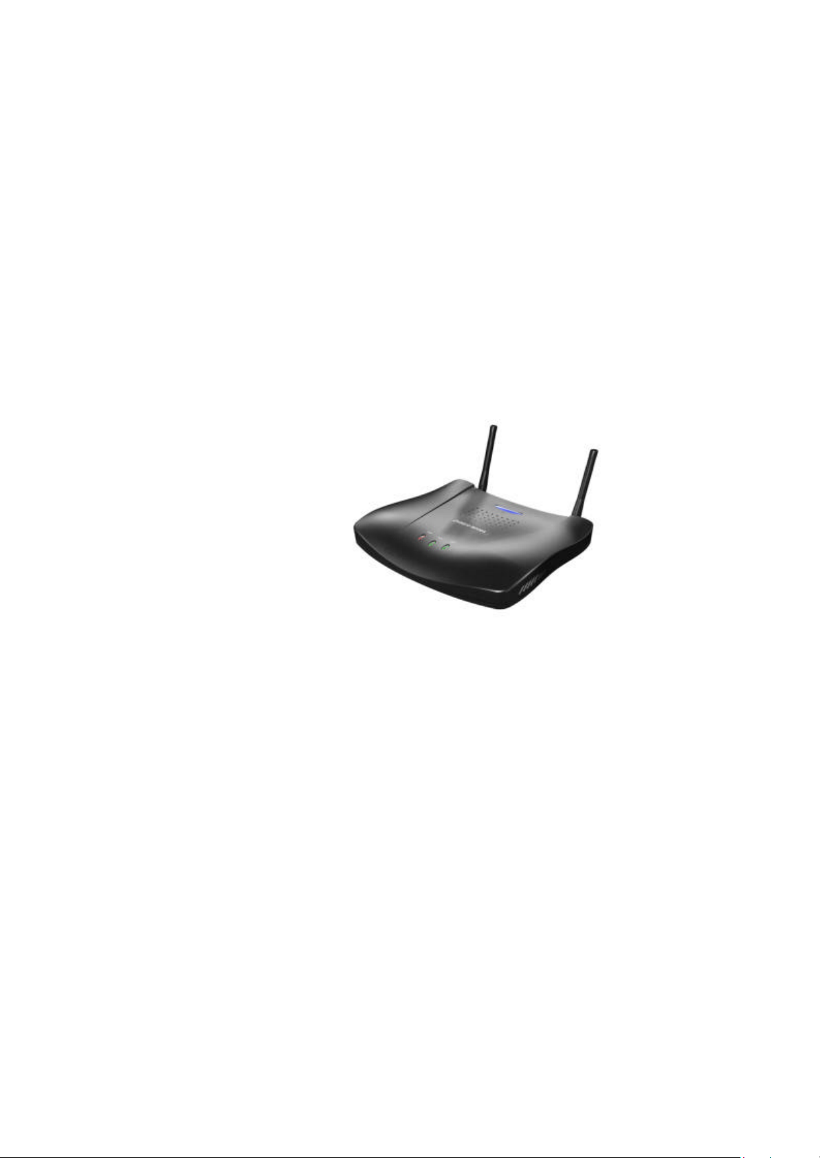
W800A appearance is shown in Fig. 3.1-1.
Fig. 3.1-1 W800A Appearance
The hardware of W800A comprises the main body, antenna and external power adapter.
The software of W800A comprises the basic service subsystem and network
management subsystem.
= The basic service subsystem consists of these items: 802.11a/b/g AP driving,
802.3 Ethernet driving, transparent bridge connection, load balance, TCP/IP
protocol stack, dynamic address distribution, static MAC address filtration, SSH,
QoS control and VLAN.
= The network management subsystem consists of these items: SNMP Agent,
command line configuration module (Telnet configuration and serial interface
configuration), WEB page configuration module.
The main board of W800A has two MiniPci wireless network card slots, one or both of
them can be used as required. Through software mode, different MiniPci wireless
3-1

ZXR10 WAS (V2.0) IP Wireless Access System W800A Wireless Access Point User’s Manual
network cards can be set as different working modes: 802.11a, 802.11b, 802.11g and
802.11b/g. So, W800A can satisfy 5 GHz based on 802.11a standard or 2.4 GHz single
frequency wireless access function based on 802.11 b/g standard, to provide 54 Mbps
access capacity, and it can also satisfy 2.4 GHz and 5 GHz double frequency wireless
access functions based on 802.11 a/b/g, to provide 2 × 54 Mbps access capacity.
The configuration mode of the W800A wireless network card is shown in Table 3.1-1.
Table 3.1-1 Configuration Table of MiniPci Wireless Network Card for W800A
Network Card
Quantity
1 2.4 GHz (802.11 b/g standard working mode)
1 5 GHz (802.11a standard working mode)
2
2
2
2.4 GHz (802.11 b/g
standard working mode)
2.4 GHz (802.11 b/g
standard working mode)
5 GHz (802.11a standard
working mode)
Network Card Types Function Descriptions
2.4 GHz (802.11 b/g
standard working
mode)
5 GHz (802.11a
standard working
mode)
5 GHz (802.11a
standard working
mode)
& Note:
802.11 b/g standard single frequency wireless
access, with the maximum capacity of 54Mbps.
802.11a standard single frequency wireless
access, with the maximum capacity of 54Mbps.
802.11 b/g standard single frequency wireless
access, with the maximum capacity of 2 ×
54Mbps.
802.11 a/b/g standard double frequency wireless
access, with the maximum capacity of 2 ×
54Mbps.
802.11a standard single frequency wireless
access, with the maximum capacity of 2 ×
54Mbps.
Considering the interference owing to close distance between two network cards in one
AP , it is not recommended that two network cards are configured with the same
frequency mode, when two network cards are used.
3.2 Units/Components
3.2.1 Front Panel
There are three LED indicators on the front panel of the W800A, indicating the
equipment status. The meanings of LED indicators are shown in Table 3.2-1.
3-2
Indicators Descriptions
Power It is W800A power indicator. On: Indicating that the power supply is on.
RUN During normal operation, the RUN indicator flashes slowly once per second.
ACT
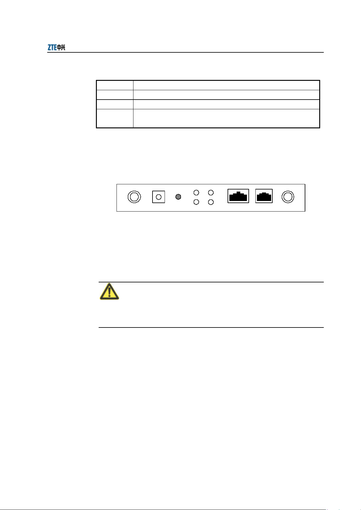
3.2.2 Rear Control Panel
There are many interfaces and indicators on the rear control panel of W800A, as shown
in Fig. 3.2-1.
Chapter 3 Structure and Principle
Table 3.2-1 Description of Indicators on W800A Panel
It is the wireless network status indicator. When W800A wireless interface works
normally, this indicator is always on.
Status indicators
Fig. 3.2-1 Schematic Diagram of the Rear Control Panel of W800A
Ethernet CONSOLEANT ANT12V DC DEFSET
The indicators and interfaces on the rear control panel are described as follows:
1. 12V DC (Power supply jack)
Connecting the power adapter.
Note:
Only the accessory power adapter can be used. Never use other power adapters,
otherwise, equipment may be damaged.
2. DEFSET (Default button)
This button serves to reset the W800A and recover the ex-factory default
parameter configuration.
3. Status indicator
10M: ON indicates that Ethernet is connected to the opposite device at the rate
of 10 Mbps.
100M: ON indicates that Ethernet is connected to the opposite device at the rate
of 100 Mbps.
ACT: Flash indicates that Ethernet is receiving or transmitting data.
3-3

ZXR10 WAS (V2.0) IP Wireless Access System W800A Wireless Access Point User’s Manual
ALARM: It is the alarm indicator. ON indicates that the device works
abnormally.
4. Ethernet (Ethernet RJ45 interface)
The interface features three functions:
1) When the W800A works normally in the network, this interface serves as the
W800A uplink interface, to connect W112P/W105P through the straight through
power supply Ethernet cable (AP remote power supply mode), or connect the
Ethernet switch downlink interface through the straight through Ethernet cable
(using power adapter to power local AP).
2) Before the W800A is installed, this interface can connect with PC wired network
interface through the crossed network cable, and then you can log on to the
W800A in the WEB or Telnet mode to configure W800A parameters.
3) When a version is loaded to the W800A through the hyper terminal, connect this
interface to the PC wired network interface through a crossed network cable and
run FTP/TFTP server application software on the PC, to load the running
version file to the W800A system.
5. CONSOLE (RJ11 interface for configuration)
It is connected to the PC serial interface through a serial interface cable, to
implement version loading, configuration and debugging to the device through
the hyper terminal.
6. ANT (Antenna interface)
It serves for installing the antenna.
3.3 Networking Modes
The W800A provides wireless access for the indoor wireless users. It can be placed in
such positions as office area, lobby or corridor of a hotel.
As the access equipment of wireless and wired network, the W800A provides users
with wireless access to Ethernet and data service access. Through different hardware
and software configurations, the W800A can construct different modes.
1. AP mode: The W800A implements BSS access to connect BSS to DS, and
supports wireless STA access.
3-4
 Loading...