

ZTE ZXR10W800A Professional Installation Manual

ZXR10 WAS (V2.0) IP Wireless Access
System
W800A Wireless Access Point
Professional Installation
Instruction Manual
ZTE CORPORATION

ZXR10 WAS (V2.0) IP Wireless Access System
W800A Wireless Access Point
Professional Installation Instruct ion Manual
Manual Version 20040306-R1.0
Product Version V2.0
BOM ЧЧЧЧЧЧЧЧ
Copyright © 2003 ZTE Corporation
All rights reserved.
No part of this documentation may be excerpted, reproduced, translated, annotated or
duplicated, in any form or by any means without the prior written permission of ZTE
Corporation.
ZTE CORPORATION
ZTE Plaza, Keji Road South, Hi-Tech Industrial Park, Nanshan District, Shenzhen, P. R. China
Website: http://www.zte.com.cn
Post code: 518057
Customer Support Center: (+86755) 26770800 800-830-1118
Fax: (+86755) 26770801
E-mail: 800@zte.com.cn
* * * *
S.N.: DDDDDDDDD
FAX: +86-755-26770160
Suggestions and Feedback
To improve the quality of ZTE product documentation and offer better services to our customers, we hope
you can give us your suggestions and comments on our documentation and fax this form to
0086-755-26770160; or mail to “ZTE Plaza, Keji Road South, Hi-Tech Industrial Park, Nanshan District,
Shenzhen, P. R. China”. Our postcode is 518057.
Document Name ZXR10 WAS (V2.0) IP Wireless Access System W800A Wireless Access Point User’s Manual
Product version V2.0 Document version 20040306-R1.0
Equipment installation time
Your information
Name Company
Postcode Company address
Telephone E-mail
Good Fair Average Poor Bad
Overall
Instructiveness
Your evaluation
of this
documentation
Your suggestion
on the
improvement of
this
documentation
Your other
suggestions on
ZTE product
documentation
Index
Correctness
Completeness
Structure
Illustration
Readability
Overall
Instructiveness
Index
Correctness
Completeness
Structure
Illustration
Readability


Preface
About This Manual
This manual, ZXR10 WAS (V2.0) IP Wireless Access System W800A Wireless Access
Point — User’s Manual, is applicable to W800A wireless access point (W800A for
short) of the ZXR10 WAS (V2.0) IP wireless access system.
The ZXR10 WAS IP wireless access system is the IP wireless access system developed
by ZTE. It consists of a series of wireless access network products, such as wireless
network card, wireless access point (AP) and DSL 2-in-1 wireless router.
Serving as the operation guide to W800A, this manual introduces the function features,
installation, operation, using and maintenance of W800A. This manual consists of 7
chapters and 2 appendixes.
Conventions
Chapter 1, Safety Precautions, introduces the safety precautions of this product and
safety symbols used in this manual.
Chapter 2, Installation and Debugging, deals with the installation and debugging
methods of W800A.
Chapter 3, Command Line Configuration, covers the command line configurations of
W800A.
Appendix B, Making of Ethernet cables, details the power supply mode of W800A
Ethernet and making of Ethernet cables.
Four striking symbols are used throughout this manual to emphasize important and
critical information during operation:
Attention, Caution, Warning and Danger: alerting
you to pay attention to something.

Statement: The actual product may differ from what is described in this
manual due to frequent update of ZTE products and fast development of
technologies. Please contact the local ZTE office for the latest updating
information of the product.
Warning
This instruction manual only apply to W800A with the following antennas:
TQJ-5800BKF40-W, TQJ-5800C-5, TQJ-5800BKF8, R0322-025

Contents
1 Safety Precautions...................................................................................................................1-1
1.1 Safety Precautions .............................................................................................................1-1
1.2 Symbol Description ...........................................................................................................1-2
2 Installation and Debugging.......................................................................................................2-1
2.1 Installation Preparations .....................................................................................................2-1
2.1.1 Installation Preparation Flow .......................................................................................2-1
2.1.2 Tool, Instrument and Document...................................................................................2-3
2.1.3 Installation Environment Inspection.............................................................................2-4
2.1.4 Unpacking Inspection.................................................................................................2-4
2.2 Installation ........................................................................................................................2-4
2.3 Power-on and Power -off.....................................................................................................2-6
2.4 Debugging ........................................................................................................................2-6
3 Command Line Configuration..................................................................................................3-1
3.1 Overview..........................................................................................................................3-1
3.2 User Mode........................................................................................................................3-4
3.2.1 Entering the Privileged Mode ......................................................................................3-4
3.2.2 Exiting the Telnet Configuration..................................................................................3-4
3.3 Privileged Mode................................................................................................................3-5
3.3.1 Network Connectivity Check......................................................................................3-5
3.3.2 Saving the Configuration Data to FLASH .....................................................................3-5
3.3.3 Restoring the Default Configuration.............................................................................3-5
3.3.4 Resetting the Software................................................................................................3-6
3.3.5 Entering the Configure Mode......................................................................................3-6
-i-

-
3.3.6 Exiting the Privileged Mode.......................................................................................3-6
3.3.7 Exiting the Telnet Configuration .................................................................................3-6
3.4 Configure Mode................................................................................................................3-6
3.4.1 Bridge Configuration.................................................................................................3-7
3.4.2 Clearing the Information............................................................................................3-7
3.4.3 Configuring the Configuration Server ..........................................................................3-8
3.4.4 DHCP Server Configuration .......................................................................................3-8
3.4.5 DISCOVER Configuration....................................................................................... 3-10
3.4.6 802.1X Parameter Configuration................................................................................3-11
3.4.7 Password Configuration in the Privileged Mode .......................................................... 3-14
3.4.8 Erasing the Filtration Rules ...................................................................................... 3-14
3.4.9 Exiting the Configure Mode ..................................................................................... 3-14
3.4.10 IAPP Load Balanc e Configuration ........................................................................... 3-15
3.4.11 Entering the Interface Configuration Mode ............................................................... 3-16
3.4.12 IP Network Parameter Configuration ....................................................................... 3-17
3.4.13 Kicking Users....................................................................................................... 3-18
3.4.14 Two -Layer Separation Configuration....................................................................... 3-18
3.4.15 Log Printing Message Configuration........................................................................ 3-19
3.4.16 MAC Filtration Configuration................................................................................. 3-20
3.4.17 MAC Address Authentication Configuration ............................................................. 3-21
3.4.18 Manager Configuration .......................................................................................... 3-21
3.4.19 QoS Configuration ................................................................................................ 3-22
3.4.20 RADIUS Server Configuration ................................................................................ 3-22
3.4.21 SNMP Module Configuration .................................................................................. 3-24
3.4.22 SSH Parameter Configuration ................................................................................. 3-28
3.4.23 Spanning Tree Parameter Configuration ................................................................... 3-29
-ii

3.4.24 TELNET Configuration .......................................................................................... 3-32
3.4.25 Uploading/Downloading TFTP Files ........................................................................ 3-32
3.4.26 VLAN Configuration ..............................................................................................3-33
3.4.27 Web Configuration................................................................................................. 3-34
3.4.28 Nation Zone Configuration ......................................................................................3-34
3.4.29 Showing Parameter Configuration ............................................................................3-35
3.5 Ethernet Interface Configuration Mode ...............................................................................3-41
3.5.1 Exiting the Ethernet Interface Configuration Mode ...................................................... 3-42
3.5.2 Ethernet Interface MAC Filtration Configuration ......................................................... 3-42
3.6 Wireless Interface Configuration Mode .............................................................................. 3-42
3.6.1 802.11 -Related Parameter Configuration of the Wireless Interface.................................3-42
3.6.2 ESSID Hiding Configuration .....................................................................................3-45
3.6.3 Exiting the Wireless Interface Configuration Mode ...................................................... 3-46
3.6.4 Enabling the Link Integrity Detection Function ........................................................... 3-46
3.6.5 Wireless Interface MAC Filtration Configuration......................................................... 3-46
3.6.6 Multi-ESSID Configuration ...................................................................................... 3-46
3.6.7 Security Parameter Configuration .............................................................................. 3-47
3.6.8 Transmission Power Configuration ............................................................................ 3-49
3.6.9 Working Mode Configuration.................................................................................... 3-49
A.1 Making of Ethernet Cables....................................................................................................1
A.1.1 Making of Straight Through Ethernet Cables (RJ45).........................................................1
A.1.2 Making of Straight Through Power Supply Ethernet Cables (C-RJ45-001)..........................1
A.1.3 Making of Crossover Ethernet Cables (RJ45J).................................................................2
A.1.4 Ethernet Cable Label....................................................................................................3
-iii-


A List of Figures
Fig. 2.1-1 Sub-Channel Distribution ........................................................................................2-1
Fig. 2.1-2 Channel Distribution Principle of Adjacent APs.........................................................2-2
Fig. 2.2-1 installation instruction ............................................................................................2-5
Fig. 2.2-2 Soldered Connectors...............................................................................................2-6
Fig. 3.-1 Serial Port Configuration ..........................................................................................3-3
Fig. 3.1-2 Telnet to W800A....................................................................................................3-3
Fig. A.1 -1 Label of the Straight Through Ethernet Cable ...............................................................3
Fig. A.1 -2 Label of the Straight Through Power Supply Ethernet Cable ..........................................3
Fig. A.1 -3 Label of the Crossover Ethernet cable .........................................................................4
-i-


A list of Tables
Table 1.2-1 Safety Symbols and Descriptions ...........................................................................1-3
Table 2.1-1 IDs and Frequencies of Channels ...........................................................................2-2
Table 3.6-1 W800A Working Channels .................................................................................. 3-45
Table A.1-1 Connections of Straight Through Ethernet Cables (RJ45) ............................................1
Table A.1-2 Connections of Straight Through Power Supply Ethernet Cables (C-RJ45-001)..............2
Table A.1-3 Connections of Crossover Ethernet Cables (RJ45J) .....................................................2
-i-


1 Safety Precautions
This chapter introduces the safety precautions of this product and safety symbols used
in this manual.
1.1 Safety Precautions
This device complies with Part 15 of the FCC Rules. Operation is subject to the
following two conditions: ( 1) This device may not cause harmful interference, and( 2)
this device must accept any interference received, including interference that may
cause undesired operation.
To assure continued compliance, (example – use only shielded interface cables when
connecting to computer or peripheral devices). Any changes or modifications not
expressly approved by the party responsible for compliance could void the user’s
authority to operate the equipment.
NOTE: This equipment has been tested and found to comply with the limits for a Class
B digital device, pursuant to Part 15 of the FCC Rules. These limits are designed to
provide reasonable protection against harmful interference in a residential installation.
This equipment generates, uses and can radiate radio frequency energy and, if not
installed and used in accordance with the instructions, may cause harmful interference
to radio communications. However, there is no guarantee that interference will not
occur in a particular installation. If this equipment does cause harmful interference to
radio or television reception, which can be determined by turning the equipment off
and on, the user is encouraged to try to correct the interference by one of the following
measures:
- Reorient or relocate the receiving antenna.
- Increase the separation between the equipment and receiver.
- Connect the equipment into an outlet on a circuit different from that to which the
receiver is connected.
- Consult the dealer or an experienced radio/TV technician for help.
This equipment is with high temperature and voltage, so only the professional
1-1

ZXR10 WAS (V2.0) IP Wireless Access System W800A Wireless Access Point
Professional Installation Instruction Manual
personnel who had passed the training can install, operate and maintain it.
ZTE assumes no responsibility for consequences resulting from violation of general
specifications for safety operations or of safety rules for design, production and use of
equipment.
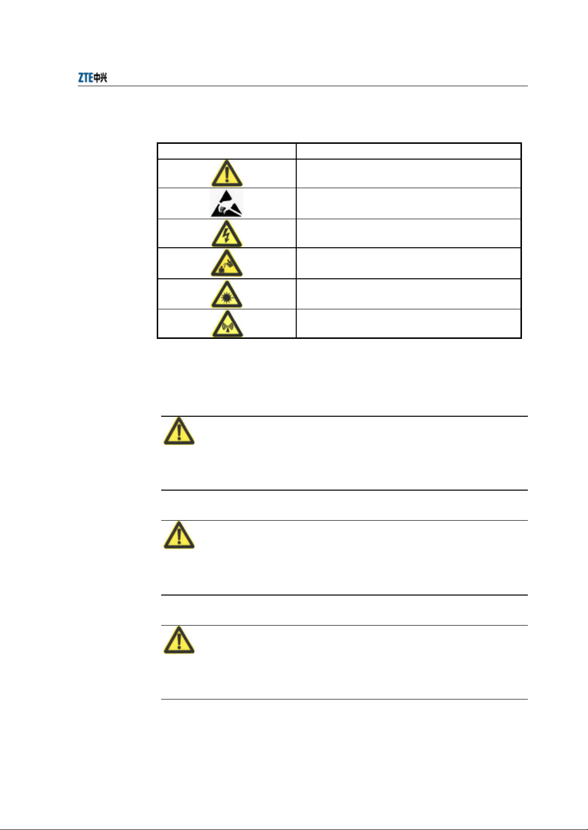
1.2 Symbol Description
See Table 1.2-1 for the safety symbols used in this manual, which serves to remind the
readers of the safety precautions to be taken when the equipment is installed, operated
and maintained.
1-2
Chapter 1 Safety Precautions
Table 1.2-1 Safety Symbols and Descriptions
Safety Symbols Meaning
Call for notice
Call for antistatic measures
Warn against electric shock
Caution against scald
Warn against laser
Caution against microwave
Four types of safety levels are available: danger, warning, caution and note. To the
right of a safety symbol is the text description of its safety level. Under the symbol is
the detailed description about its contents. See the following formats.
Danger:
Any failure to take the reminder seriously may lead to important accidents, such as
casualties or damage to the equipment.
Cautions:
Any failure to take the reminder seriously may lead to important or severe injury
accidents, or damage to the equipment.
Caution:
Any failure to take the reminder seriously may lead to severe injury accidents or
damage to the equipment.
1-3

ZXR10 WAS (V2.0) IP Wireless Access System W800A Wireless Access Point
Professional Installation Instruction Manual
Note:
Any failure to take the reminder seriously may lead to injury accidents or damage to
the equipment.
& Remark, reminder, tip…
The remarks, prompt and tips in addition to safety statements.
1-4
2 Installation and Debugging
This chapter details the methods and procedure of installation and debugging of the
W800A for your reference.
2.1 Installation Preparations
2.1.1 Installation Preparation Flow
Before installing the W800A, the engineering personnel should confirm that such work
as solution design, project survey and W800A basic configurations have been
completed. Brief introductions to the preparations required for installation are as
follows.
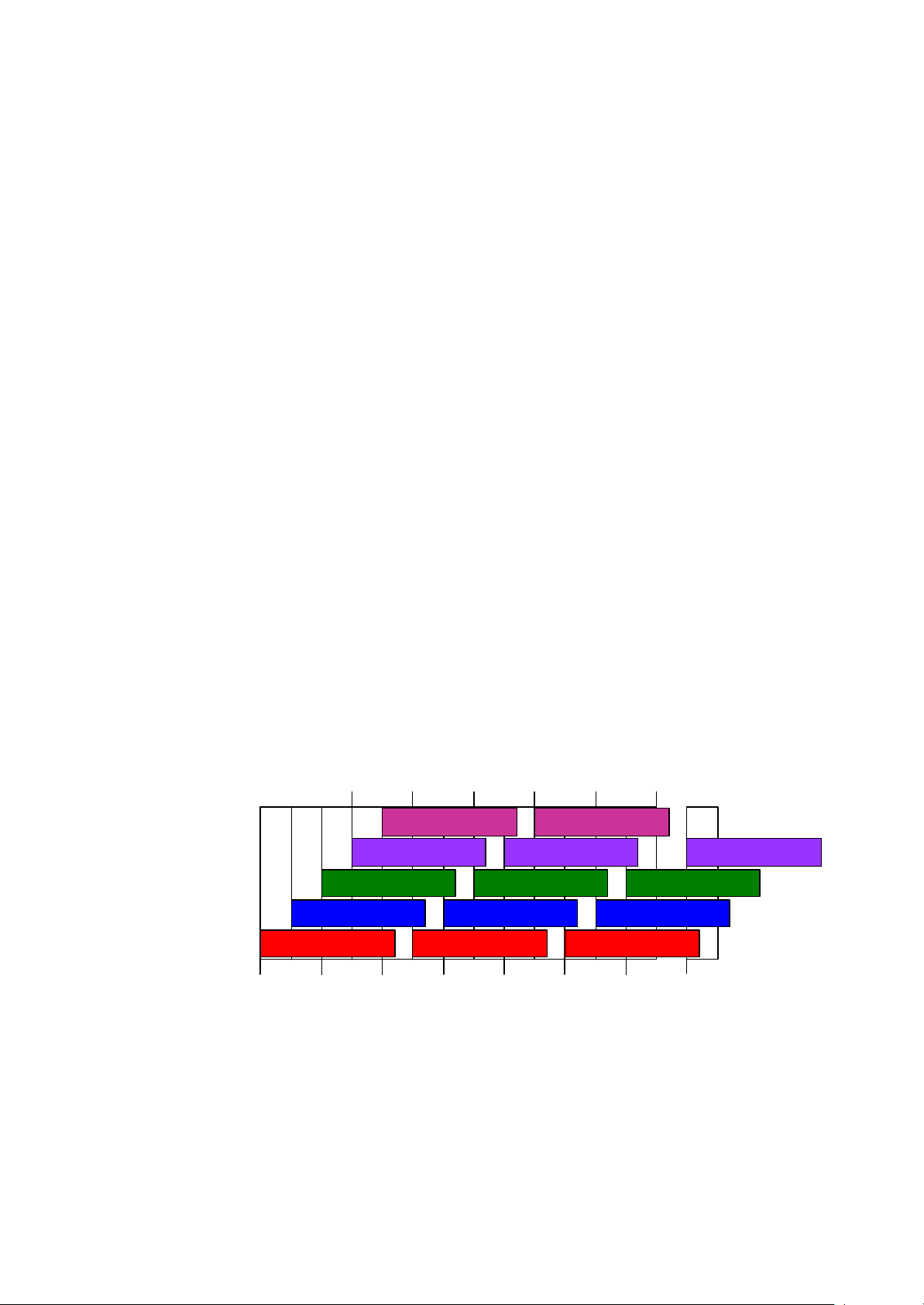
2.1.1.1 Channel Planning
According to 802.11b wireless LAN international standard and the standard of state
radio management committee, the working frequency band of a wireless device in the
wireless LAN is 2400 MHz ~ 2483.5 MHz, and the working frequency bandwidth is
83.5 MHz, divided into 14 sub-channels with 22 MHz as the bandwidth for each one.
The sub-channel distribution is shown in Fig. 2.1-1.
2.417 2.427 2.437 2.447 2.457
2.467
5 10
4
3
9
8
13
14
2 7 12
1 6 11
2.412 2.422 2.432 2.442 2.452 2.462 2.472 2.484
Fig. 2.1-1 Sub-Channel Distribution
Viewed from the above diagram, up to 13 channels are available. The IDs and central
frequencies of these 13 channels are described in Table 2.1-1.
2-1
ZXR10 WAS (V2.0) IP Wireless Access System W800A Wireless Access Point
Professional Installation Instruction Manual
Table 2.1-1 IDs and Frequencies of Channels
Channel ID Central Frequency Low End/High End Frequency of the Channel
1 2412MHz 2401/2423MHz
2 2417MHz 2411/2433MHz
3 2422MHz 2416/2438MHz
4 2427MHz 2421/2443MHz
5 2432MHz 2426/2448MHz
6 2437MHz 2431/2453MHz
7 2442MHz 2431/2453MHz
8 2447MHz 2436/2458MHz
9 2452MHz 2441/2463MHz
10 2457MHz 2446/2468MHz
11 2462MHz 2451/2473MHz
12 2467MHz 2456/2478MHz
13 2472MHz 2461/2483MHz
When multiple channels work at the same time, the central frequency intervals between
two channels should not be less than 25 MHz to avoid mutual interference. As show n
in Fig. 2.1-1, in a cell, direct spread spectrum technology can support simultaneous
work of up to 3 un-overlapped channels.
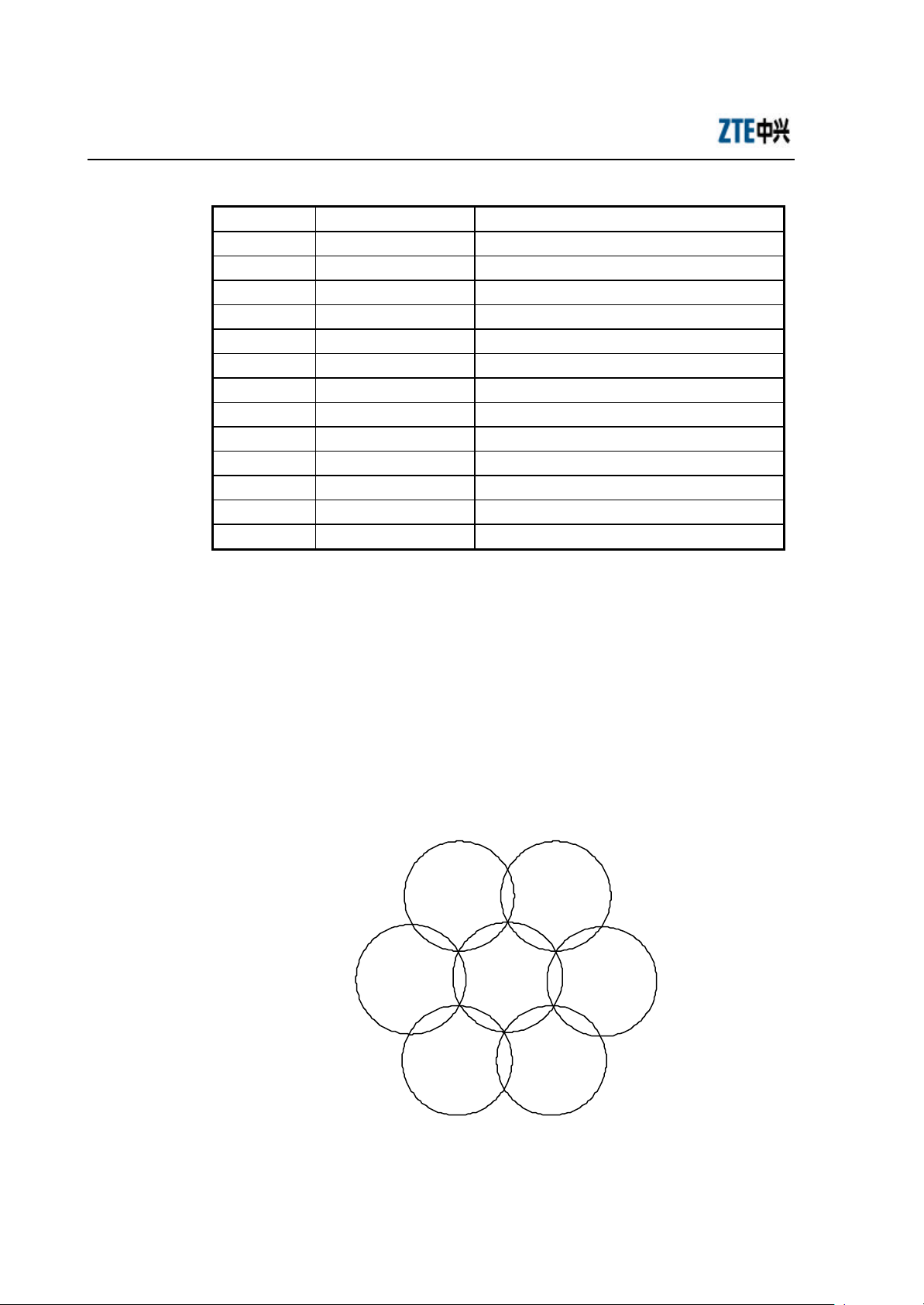
In the wireless LAN planning, to realize efficient coverage of APs and avoid mutual
interference between channels, the cellular coverage principle of BTS is adopted in the
channel distribution. 3 un-overlapped channels (for example, channels 1, 6 and 11) can
be used in the same area at the same time, as shown in Fig. 2.1-1.
channel 6
AP
channel 11
AP
AP
channel 1
AP
channel 11
AP
channel 6
AP
channel 6
AP
channel 11
Fig. 2.1-2 Channel Distribution Principle of Adjacent APs
2-2

When using APs, for the adjacent APs, we will select their working channels (channels
1, 6 and 11 are usually used) according to the principle shown in Fig. 2.1-1, to
guarantee the normal work of the wireless LAN.
The channel distribution principle of 802.11g standard is the same as that of 802.11b.
802.11a standard channels feature anti-interference performance, so no special
configuration is required. In the actual networking, you only need make sure that the
channels between adjacent APs are different.
2.1.1.2 Configuration before Installation
Before the installation, power on W800As in turn and check whether they can work
normally. In the normal case, the Power indicator and ACT indicator on the W800A
panel should be always on, and the RUN indicator should flash slowly (about once per
second). If the indicator is not in the normal status, you can log on to the W800A in the
hyper terminal mode and check whether the version is loaded normally. If necessary,
Chapter 4 Installation and Debugging
you can reload the version (refer to Section 7.3 Version Loading and Upgrade for
detailed procedure).
When you make sure that the W800A works normally, it is required to implement basic
configurations for it. The configuration contents are as follows:
1. Configuring the W800A IP addresses, that is, management addresses. At least
one management address should be configured for each W800A, for the
management configuration of W800A.
2. Configuring the wireless working mode of the W800A wireless interface and the
SSID (Service ID), using channel and rate of the corresponding wireless
interface.
The detailed configuration methods will be introduced in the subsequent sections.
2.1.2 Tool, Instrument and Document
= One wireless network card.
= One PC for configuration management
= ZXR10 WAS (V2.0) IP Wireless Access System W800A Wireless Access Point —
User’s Manual
2-3

ZXR10 WAS (V2.0) IP Wireless Access System W800A Wireless Access Point
Professional Installation Instruction Manual
2.1.3 Installation Environment Inspection
The W800A can only be used indoors. To guarantee the normal work and longer useful
life of the equipment, the indoor temperature range should be -5 °C ~ 45 °C, you
should maintain good ventilation and dry air indoors, and the relative humidity range is
5% ~ 95%.
2.1.4 Unpacking Inspection
Generally, the following equipment and accessories are contained in the package of this
product.
W800A 1
Power adapter 1
Console configuration cable 1
Delivery attached document CD 1
& Note:
Please refer to the packing list in the package. If there is any missing part, please
contact ZTE Cooperation.
2.2 Installation
W800A shell is made in plastic with certain mechanical intensity, and can satisfy the
using requirement. The material is fire-resistant and satisfies the environment
protection requirement. The ground bolt can be installed on the interface board of the
shell, for grounding. The W800A can be used not only on the desktop or ceiling but
also on the wall, so it is easily to be used.
The W800A installation process is described in detail as follows:
1. Place the W800A to the proper position according to the engineering planning,
for example, evenly place it on the desktop, ceiling or wall.
2. Determine the angle of the antenna.
3. Connect the power cable to the power socket on the W800A backplane.
4. Connect the Ethernet cable to the Ethernet interface on the W800A backplane.
2-4
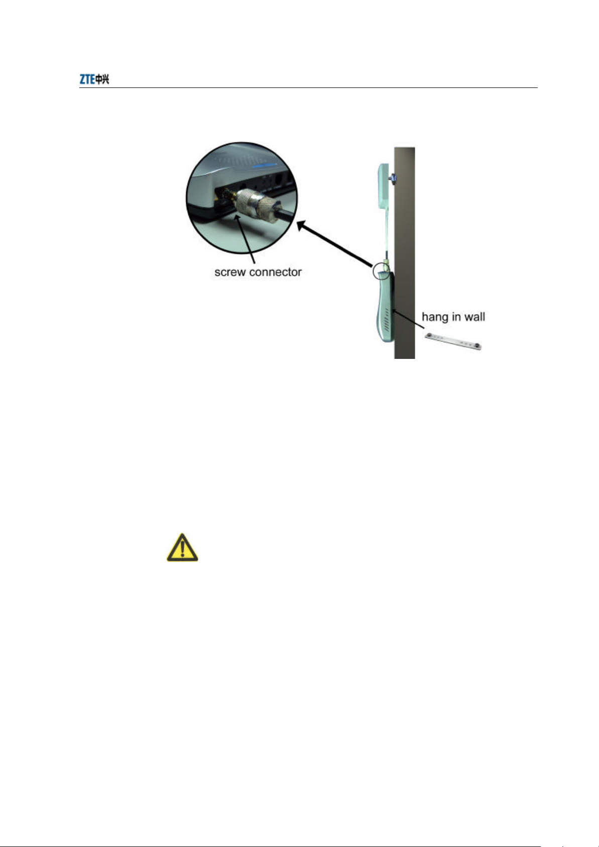
Chapter 4 Installation and Debugging
Fig. 2.22-1 installation instruction
When the W800A is installed on the ceiling, for the ceiling in plaster or floor, the
W800A antenna can be directly installed on the ceiling; for the ceiling in metal, if the
antenna is directly installed on the ceiling, the antenna signal will be shielded and
W800A can not work normally, so you should lead the antenna to the place under the
ceiling, through correct antenna feeder. If the W800A is hanged on the wall, reliable
fixing method is necessary. If the W800A is placed on the desktop, reliable fixing
method is required to ensure the safety of the equipment.
Warning
5. Once the RF antenna connector is screwed onto the W800A, the connectors must
be rendered "permanent" and non-disconnectable in accordance with FCC rules.
This can be accomplished either by;
a) Soldering the connectors together, (see Fig. 2.22-2) or,
2-5

ZXR10 WAS (V2.0) IP Wireless Access System W800A Wireless Access Point
Professional Installation Instruction Manual
Fig. 2.22-2 Soldered Connectors
b) Gluing together by using permanent, fast-setting epoxy glue and surround the
entire periphery of the connector junction so it is not possible to disconnect.
Follow the directions provided on the glue package for cleaning and mixing the
two-part glue together.
2.3 Power-on and Power- off
The following two power methods are used for the W800A system.
1. Use the in -house power adapter of the W800A.
2. Use PoE.
The terminal PoE module is embedded in the W800A. When PoE power supply is
adopted, a standard straight-through cable is used to connect the PoE interface of the
PoE source end device W112P or W105P. For the detailed description, refer to
Appendix B.
To power on the W800A, connect the power adapter or Ethernet cable for powering the
Ethernet for the W800A. After being powered on, the W800A will start automatically,
without any operation by users.
To power off the W800A, directly disconnect the W800A power adapter or the cable
for powering Ethernet.
2.4 Debugging
After W800A is powered on and started, it is required to implement service debugging.
There are three purposes for debugging:
2-6
 Loading...