

ZTE ZXR10W200A Users Manual

ZXR10 WAS (V1.0) IP Wireless Access
System
W200A Wireless Access Point
User’s Manual
ZTE CORPORATION

ZXR10 WAS (V1.0) IP Wireless Access System
W200A Wireless Access Point
User’s Manual
Manual Version 20040306-R1.0
Product Version V1.0
BOM ЧЧЧЧЧЧЧЧ
Copyright © 2003 ZTE Corporation
All rights reserved.
No part of this documentation may be excerpted, reproduced, translated, annotated or
duplicated, in any form or by any means without the prior written permission of ZTE
Corporation.
ZTE CORPORATION
ZTE Plaza, Keji Road South, Hi-Tech Industrial Park, Nanshan District, Shenzhen, P. R. China
Website: http://www.zte.com.cn
Post code: 518057
Customer Support Center: (+86755) 26770800 800-830-1118
Fax: (+86755) 26770801
E-mail: 800@zte.com.cn
* * * *
S.N.: DDDDDDDDD

FAX:0086-755-26770160
Suggestions and Feedback
To improve the quality of ZTE product documentation and offer better services to our customers, we hope
you can give us your suggestions and comments on our documentation and fax this form to
0086-755-26770160; or mail to “
Shenzhen, P. R. China”. Our postcode is 518057.
Document Name ZXR10 WAS (V1.0) IP Wireless Access System W200A Wireless Access Point Us er’s Manual
Product version V1.0 Document version 20040306-R1.0
Equipment installation time
Your information
Name Company
Postcode Company address
Telephone E-mail
Good Fair Average Poor Bad
Overall
Instructiveness
Your evaluation
of this
documentation
Your suggestion
on the
improvement of
this
documentation
Your other
suggestions on
ZTE product
documentation
Index
Correctness
Completeness
Structure
Illustration
Readability
Overall
Instructiveness
Index
Correctness
Completeness
Structure
Illustration
Readability
ZTE
Plaza, Keji Road South, Hi-Tech Industrial Park, Nanshan District,


Preface
About This Manual
This manual is used for ZXR10 WAS (V1.0) IP Wireless Access System W200A
Wireless Access Point (hereinafter called W200A).
ZXR10 (V1.0) IP Wireless Access System is developed independently by ZTE
CORPORATION. It is composed of a range of wireless access products, including
wireless network card and wireless router with combined functions of AP and DSL.
This manual presents the functional characteristics, installation, ope ration, usage and
maintenance of W200A, and is used as the operation guide for this product. This
manual contains 8 chapter and 2 appendices.
Chapter 1: Safety Instructions. It presents the safety requirements in operations and
safety signs used in this manual.
Chapter 2: Overview. It presents the functions, features and technical parameters of
W200A.
Chapter 3: Structure and Principle It presents the structure and principle of W200A.
Chapter 4: Installation and Debugging It presents the installation and debugging
methods for W200A.
Chapter 5: Command Line Configurations It presents the command line configurations
of W200A.
Chapter 6: WEB configurations. It presents the web configurations of W200A.
Chapter 7: Integrated GUI Management. It presents the integrated GUI Integration
management of W200A.
Chapter 8: Maintenance It presents the methods of routine maintenance and version
upgrade.
Appendix A: Package, Transportation and Storage It presents the packing methods,
storage conditions and transportation requirements of W200A.
Appendix B: Making Ethernet cables It presents the Ethernet power supplies for
W200A and the methods to make network cables.

Statement: The actual product may differ from what is described in this
manual due to frequent update of ZTE products and fast development of
technologies. Please contact the local ZTE office for the latest updating
information of the product.

Contents
1 Safety Statements....................................................................................................................................1-1
1.1 Safety Precautions..........................................................................................................................1-1
1.2 Symbol Description........................................................................................................................1-2
2 Overview..................................................................................................................................................2-1
2.1 Introduction....................................................................................................................................2-1
2.2 Functions and Features...................................................................................................................2-1
2.3 Te chnical Characteristics and Parameters......................................................................................2-2
3 Structure and Principle...........................................................................................................................3-1
3.1 Structure and Working Principle ....................................................................................................3-1
3.2 Units and Components...................................................................................................................3-1
3.2.1 Front Panel..........................................................................................................................3-1
3.2.2 Rear Control Panel......... .................................................. ... ................................................3-2
3.3 Network Mode ...............................................................................................................................3-3
4 Installation and Debugging ....................................................................................................................4-1
5 Command Line Configurations .............................................................................................................5-1
5.1 Overview........................................................................................................................................5-1
5.2 User Mode......................................................................................................................................5-4
5.3 Privileged Mode.............................................................................................................................5-4
5.3.1 Command to Test Network Connectivity............................................................................5-4
5.3.2 Command to Save Configurations to Flash.........................................................................5-5
5.3.3 Command to Reset Software...............................................................................................5-5
5.3.4 Command to Enter Configure Mode...................................................................................5-5
5.3.5 Command to Exit Privileged Mode.....................................................................................5-5
-i-

5.3.6 Command to Exit TELNET Configuration.........................................................................5-6
5.4 Configure Mode........ ..................................................... .. ... ...........................................................5-6
5.4.1 Commands to Configure Wireless Access-Bridge..............................................................5-6
5.4.2 Command to Configure Bridge Information....................................................................... 5-7
5.4.3 Commands to Configure DHCP Server.............................................................................. 5-7
5.4.4 Discover commands............................................................................................................ 5-9
5.4.5 Commands to Configure 802.1X Parameters...................................................................5-10
5.4.6 Command to Set User Password in Privileged Mode....................................................... 5-13
5.4.7 Command to Delete Filtration Rules................................................................................5-13
5.4.8 Command to Exit Configuration Mode ............................................................................5-13
5.4.9 Commands to Configure IAPP (Load-balance) ................................................................5-14
5.4.10 Interface Skip.................................................................................................................. 5-15
5.4.11 Commands to Configure Layer 2 Isolation..................................................................... 5-16
5.4.12 Commands to Configure IP network Parameters............................................................5-16
5.4.13 Command to Configure Log Print Information .............................................................. 5-17
5.4.14 Command to Configure MAC Filter............................................................................... 5-18
5.4.15 Command to Configure MAC Address Authentication..................................................5-19
5.4.16 Command to Configure Users ........................................................................................ 5-20
5.4.17 Commands to Configure Radius Server ......................................................................... 5-20
5.4.18 Command to Configure SNMP Module .........................................................................5-22
5.4.19 Command to Manage Telnet Idle Timeout ..................................................................... 5-26
5.4.20 Commands to Upload/download TFTP Files..................................................................5-26
5.4.21 Commands to Configure VLAN.....................................................................................5-28
5.4.22 Show Commands............................................................................................................5-29
5.5 Ethernet Interface Configuration Mode...................... ... .. ... .. ................................................... .. ..5-34
5.5.1 Configurations in the Ethernet Interface Mode................................................................. 5-34
-ii-

5.5.2 Command to Exit the Ethernet Interface Configuration Mode ....................... .. ... .. ... ........5-35
5.5.3 Command to Configure Ethernet interface IP addresses...................................................5-35
5.5.4 Command to Configure MAC filter for the Ethernet Interface.........................................5-35
5.6 Wireless Interface Configuration Mode.......................................................................................5-35
5.6.1 Command to Configure 80211b-related Parameters for the Wireless Interface................5-36
5.6.2 Command to Exit Wireless Interface Configuration Mode...............................................5-38
5.6.3 Command to Enable Link Integrity Detection..................................................................5-38
5.6.4 WEP Configuration of the Wireless Interface ...................................................................5-39
5.6.5 Command to Configure MAC Filter in Wireless Interface Configuration........................5-40
5.6.6 Command to Configure Authentication Mode in Wireless Interface Configuration.........5-41
6 WEB Configuration ................................................................................................................................6-1
6.1 Overview........................................................................................................................................6-1
6.2 Opening the login WEB page.........................................................................................................6-3
6.3 Main menu of WEB configuration.................................................................................................6-4
6.3.1 Home page (basic product information)..............................................................................6-5
6.3.2 Stations page .......................................................................................................................6-6
6.3.3 Statistics Page......................................................................................................................6-7
6.3.4 Load Balance page..............................................................................................................6-8
6.3.5 SNMP page .........................................................................................................................6-9
6.3.6 Security page.....................................................................................................................6-16
6.3.7 Save page ..........................................................................................................................6-20
6.3.8 Reboot page.......................................................................................................................6-21
6.3.9 Advanced options page .....................................................................................................6-22
6.3.10 Accounts page.................................................................................................................6-30
6.4 Interfaces page .............................................................................................................................6-31
6.4.1 Ethernet Interface page .....................................................................................................6-31
-iii-

6.4.2 Wireless Interface page.....................................................................................................6-33
6.5 Data submission flow for WEB configuration........................... ... .. ... .......................................... 6-37
7 Maintenance............................................................................................................................................7-1
7.1 Explanation..................................... ... ..................................................... .. ... .................................. 7-1
7.2 Daily Maintenance. ..................................................... .................................................... ...............7-2
7.3 Version Upload & Upgrade............................................................................................................ 7-2
7.3.1 BOOT Loading...................................................................................................................7-3
7.3.2 Online TFTP Loading.......................................................................................................7-11
Appendix A Packaging, Transportation & S torage................................................................................ A-1
A.1 Packaging......... ... .. ....................................................................................................................... A-1
A.2 Transportation.............................................................................................................................. A-1
A.3 Storage......................................................................................................................................... A-1
Appendix B Making Ethernet Cables......................................................................................................B-1
B.1 Application of the W200A ............................................................................................................B-1
B.2 How to Make an Ethernet Cable...................................................................................................B-3
B.2.1 Making a Straight-through Ethernet Cable (RJ45)...................... .. ... .. ................................B-3
B.2.2 Making a PoE Ethernet Cable (C-RJ45-001)................................... .. ... ... .. ........................B-3
B.2.3 Making a Crossover Ethernet Cable (RJ45J) .....................................................................B-4
B.2.4 Ethernet Cable Labels ........................................................................................................B-5
-iv-

1 Safety Statements
This chapter introduces the safety precautions of this product and safety symbols used
in this manual.
1.1 Safety Precautions
This device complies with Part 15 of the FCC Rules. Operation is subject to the
following two conditions: (1)This device may not cause harmful interference,and
(2)
this device must accept any interference received, including interference that
may cause undesired operation.
To assure continued compliance, (example – use only shielded interfac e cables when
connecting to computer or peripheral devices). Any changes or modifications not
expressly approved by the party responsible for compliance could void the user’s
authority to operate the equipment.
NOTE: This equipment has been tested and found to comply with the limits for a Class
B digital device, pursuant to Part 15 of the FCC Rules. These limits are designed to
provide reasonable protection against harmful interference in a residential installation.
This equipment generates, uses and can radiate radio frequency energy and, if not
installed and used in accordance with the instructions, may cause harmful interference
to radio communications. However, there is no guarantee that interference will not
occur in a particular installation. If this equipment does cause harmful interference to
radio or television reception, which can be determined by turning the equipment off
and on, the user is encouraged to try to correct the interference by one of the following
measures:
- Reorient or relocate the receiving antenna.
- Increase the separation between the equipment and receiver.
- Connect the equipment into an outlet on a circuit different from that to which the
receiver is connected.
- Consult the dealer or an experienced radio/TV technician for help.
This equipment is with high temperature and voltage, so only the professional
1-1

ZXR10 WAS (V1.0) IP Wireless Access System W200A Wireless Access Point User’s Manual
personnel who had passed the training can install, operate and maintain it.
ZTE assumes no responsibility for consequences resulting from violation of general
specifications for safety operations or of safety rules for design, production and use of
equipment.
1.2 Symbol Description
See Table 1.2-1 for the safety symbols used in this manual, which serves to remind the
readers of the safety precautions to be taken when the equipment is installed, operated
and maintained.
1-2
Chapter Error! Style not defined. Error! Style not defined.
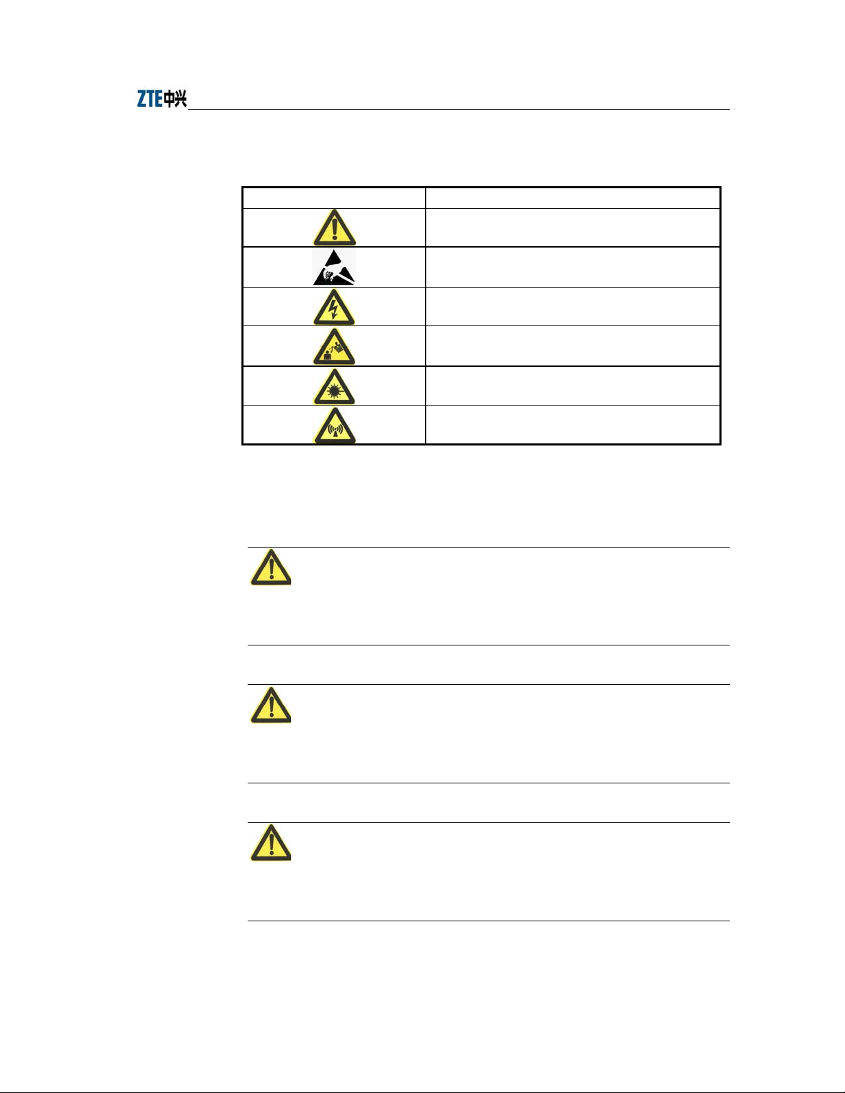
Table 1.2-1 Safety Symbols and Descriptions
Safety Symbols Meaning
Call for notice
Call for antistatic measures
Warn against electric shock
Caution against scald
Warn against laser
Caution against microwave
Four types of safety levels are available: danger, warning, caution and note. To the
right of a safety symbol is the text description of its safety level. Under the symbol is
the detailed description about its contents. See the following formats.
Danger:
Any failure to take the reminder seriously may lead to important accidents, such as
casualties or damage to the equipment.
Cautions:
Any failure to take the reminder seriously may lead to important or severe injury
accidents, or damage to the equipment.
Caution:
Any failure to take the reminder seriously may lead to severe injury accidents or
damage to the equipment.
1-3

ZXR10 WAS (V1.0) IP Wireless Access System W200A Wireless Access Point User’s Manual
Note:
Any failure to take the reminder seriously may lead to injury accidents or damage to
the equipment.
Remark, reminder, tip…
The remarks, prompt and tips in addition to safety statements.
1-4

2 Overview
This chapter presents the functions, features, technical characteristics and parameters
of W200A.
2.1 Introduction
ZXR10 WAS (V1.0) IP Wireless Access System W200A Wireless Access Point is
developed independently by ZTE CORPORATION. It is designed in full accordance
with relevant international standards. The W200A product can be used to realize single
and multiple access point connections and wireless cellular roaming within a long
range, greatly increasing the work efficiency and providing convenience for the user.
2.2 Functions and Features
W200A can offer connections to the Ethernet via UTP cables at 10/100Mbps, providing
the user with wireless access services. With a wireless network card and proper
network configurations, the user can be connected at a high speed to the LAN and then
the Internet from any place within the effective coverage range allowed by W200A.
Functions and features of W200A include:
Access rate up to 11Mbps; number of access stations up to 100.
Transparent bridging: implementing packet forwarding between Basic Service
Set (BSS) and Distributed System (DS).The maxi mu m f orwarding r a t e i s n o l e s s
than 10Mbps.
Load balancing: Internal protocols are used to provide balance of multiple APs
at the same place.
Static MAC filtration: Provide filtration of use-specified MAC addresses. Up to
100 filtration groups can be set. Each group can have up to 64 filtration rules.
Version upgrade function: Allows the upgrade of W200A software versions;
remote load of versions on-line is supported.
Built-in SNMP Agent supporting SNMP v1/2c for realizing MIB II,
IEEE802dot11-MIB, IF-MIB, EtherLike-MIB and private MIB.
2-1

ZXR10 WAS (V1.0) IP Wireless Access System W200A Wireless Access Point User’s Manual
Supports command line and Web configurations.
Provides the seamless roaming technology that allows the user to communicate
with others easily.
ESSID is used to provide network authentication, preventing illegal users from
accessing the network.
High interconnectivity. Provides interco nnections to the 10/100Mbps Ethernet,
according with IEEE 802.3 network protocols.
Provides data verification and security management; 64-bit and 128-bite WEP
encryption functions are supported.
Automatic Scale Back Functionality (ASBF) correcting WLAN automatically to
provide optimum connections.
Offers integrated management servers for the control and management of ZTE's
wireless network devices including W200A in a distributed environment.
2.3 Technical Characteristics and Parameters
Technical characteristics and specifications of W200A are shown in Table 2.3-1 below.
Table 2.3-1 Technical Parameters of W200A
Item Specifications
Standard 802.11b, 802.1d, 802.3u
Operating frequency
range
Spread spectrum system DSSS
Modulation system CCK, DQPSK, DBPSK
Error rate <10-5
Data rate 1Mbps, 2Mbps, 5.5Mbps and 11Mbps autosensing
Distance (m) 30m~100m indoors; 100m~3 00m outdoors
External interface RJ45, serial, wireless
Operation mode Half duplex
Antenna system Non-directional, 2dB gain, integrated antenna
Number of channels European Union: 13; US and Canada: 11; France: 4; Japan: 14
Recommended/maximum
number of subscribers
MAC address capacity 1024
2400MHz~2483.5MHz
30/100
2-2

Chapter Error! Style not defined. Error! Style not defined.
Item Specifications
Size
Weight 1000g (power supply not included)
Power supplies 5V DC/PoE Ethernet 48V
Power adapter
Operating temperature 0°C~ 40°C
Storage temperature -40°C~ 70°C
Operating humidity 10%~90% (no condensation)
Storage humidity 5%~95% (no condensation)
208mm×180mm×47mm
Input: 100VAC~240VAC; 50Hz~60Hz
Output: 5VDC, 1.2A
2-3

3 Structure and Principle
This chapter presents the structure and principle of W200A, including software and
hardware structure, working principle, interfaces, indicators and networking modes.
3.1 Structure and Working Principle
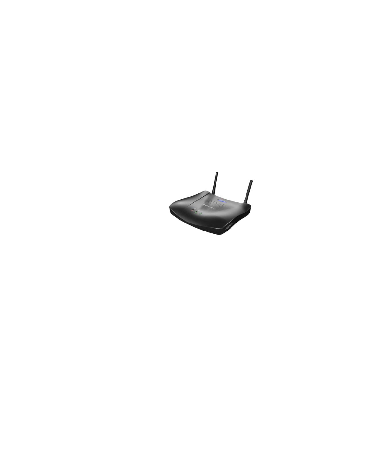
See W200A as shown in Fig. 3.1-1 below.
Hardware of W200A includes main body, antenna and external power adapter.
The software package of W200A includes the basic service subsystem and the network
management subsystem. The basic service subsystem includes 802.11b access point
driver, 802.3 Ethernet driver, transparent bridge, load balance, TCP/IP protocol suite,
dynamic address allocation and static MAC address filtration. The network
management subsystem includes SNMP Agent, command line configuration module
(including Telnet configurations and serial port configurations), Web configuration
module and integrated GUI management module.
3.2 Units and Components
3.2.1 Front Panel
On the front panel of W200A, 3 LEDs are used to indicate the status of the equipment.
The indication of each LED is shown in Table 3.2-1.
Fig. 3.1-1 Outside View of W200A
3-1
ZXR10 WAS (V1.0) IP Wireless Access System W200A Wireless Access Point User’s Manual
Table 3.2-1 W200A Panel LED Indications
LED Indication
Power
RUN
ACT
Power indicator of W200A. A lit LED indicates the power is on.
When W200A is operating normally, the RUN LED flashes slowly at an average
of 1 flash every other second.
Status indicator of the wireless network. The ACT LED is lit steadily when the
wireless interface of W20 0A is operating normally.
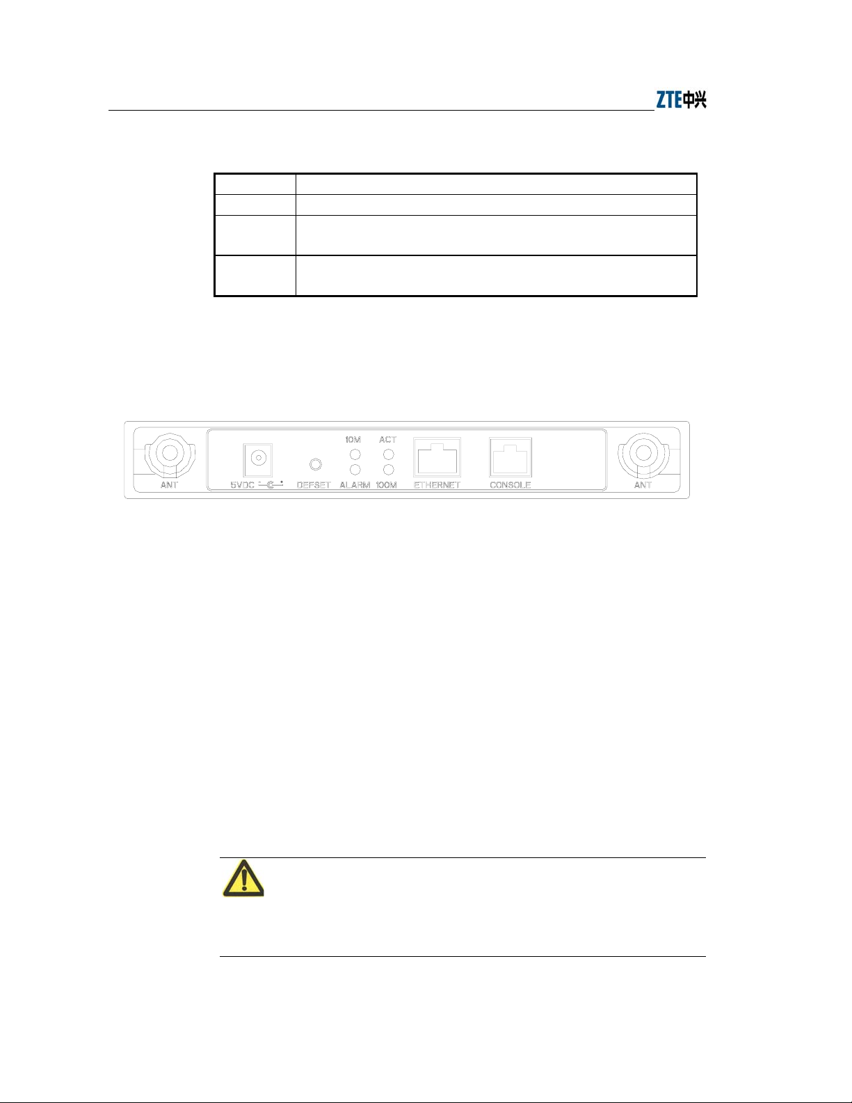
3.2.2 Rear Control Panel
On the rear control panel there are a variety of interfaces and LEDs, as show in Fig.
3.2-1.
Fig. 3.2-1 W200A Rear Control Panel Diagram
The interfaces and LEDs on the rear control panel are detailed as follows.
1. Status indicator
10M: A lit LED indicates the Ethernet is being connected to the remote
equipment at 10Mbps.
100M: A lit LED indicates the Ethernet is being connected to the remote
equipment at 100Mbps.
ACT: A flashing LED indicates the Ethernet is sending/receiving data.
ALARM: Alarm LED. A lit LED indicates the PoE is operating improperly.
2. 5V DC (power receptacle)
Used to connect the power adapter.
Note:
Only the built-in power adapter can be used. Do not connect other power adapters,
otherwise the equipment may be damaged or burnt out.
3-2

Chapter Error! Style not defined. Error! Style not defined.
3. Defset (default button)
This button is used to reset the W200A configurations to the factory presets. For
example, reset the management interface IP address of W200A to default
192.168.1.254, and subnet mask to 255.255.255.0; reset SSID (service ID) to
default zxwlan; reset the login username and password to default root and public,
and reset the privileged user password to default zte.
4. Ethernet (Ethernet RJ45 interface)
This interface has 3 functions:
1) When W200A is operating normally in a network, this interface is used as an
up-link interface and connected to W112P (AP remote power feeding mode) via
a directly powered Ethernet cable or connected (using a power adapter to supply
the AP in a near-end power mode)to the down-link interface of an Ethernet
switch via a directly connected Ethernet cable.
2) Before W200A is installed, you can connect to the wired network interfac e of a
computer via a cross network cable, log in to W200A via Web or Telnet and
configure parameters of W200A.
3) To load a version to W200A via a hyperterminal, you can connect this interface
with the wired network interface of the computer via a cross network cable, and
run FTP/TFTP server program on the computer to load the version file to the
flash of W200A.
5. CONSOLE (RJ11 interface for configurations)
Connect to the serial port of the computer using a serial cable so that you ca n
load, configure and debug the version for the equipment via the hyperterminal.
6. ANT (antenna port)
Used to install the antenna.
3.3 Network Mode
W200A is designed to provide wire access for indoor and outdoor wireless users. It can
be installed in offices, hotel halls and corridors, top of buildings, and residential yards.
The major operation modes are described as follows.
3-3
ZXR10 WAS (V1.0) IP Wireless Access System W200A Wireless Access Point User’s Manual
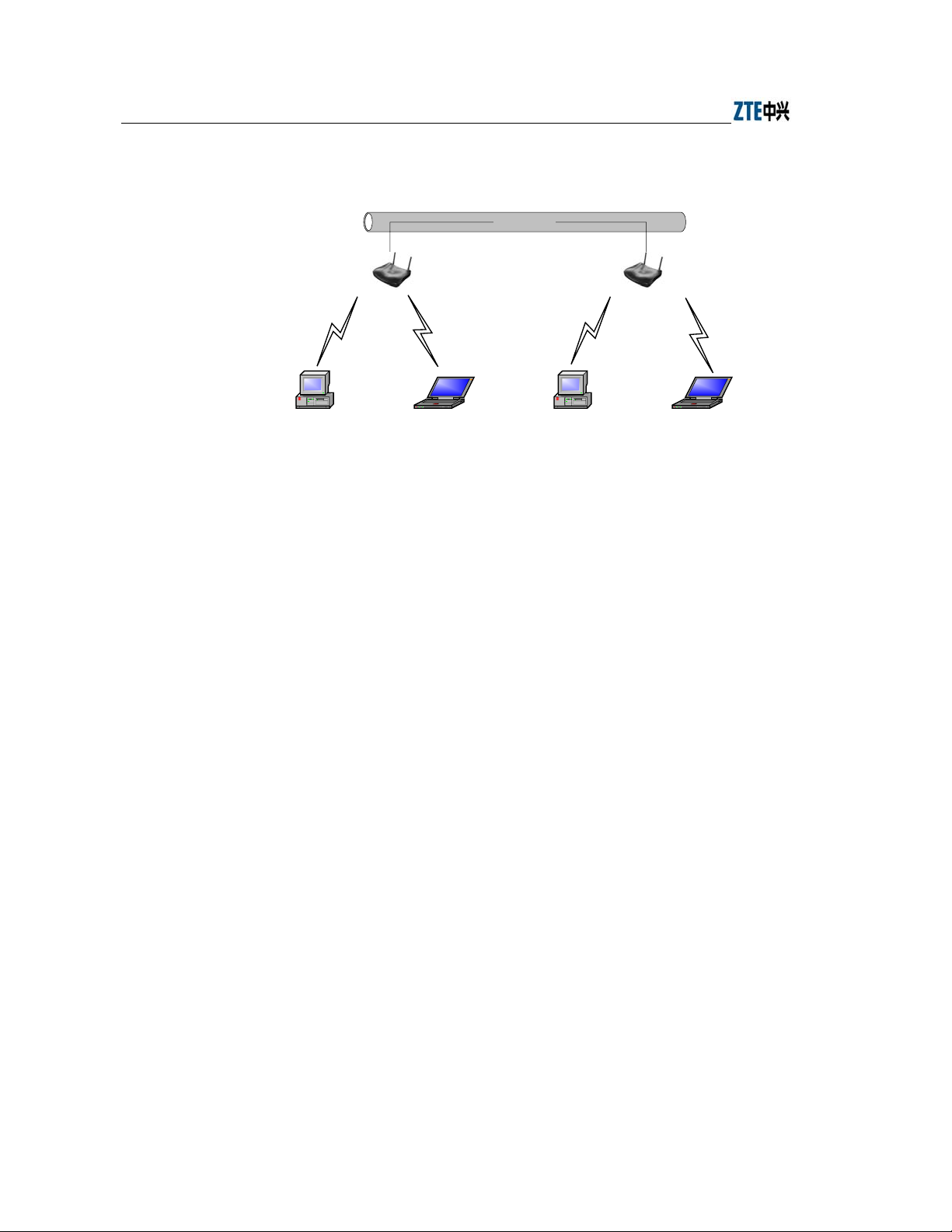
1. Establishing a small-scale wireless LAN
Wired LAN
W200A
PC Lop-top computer PC Lop-top compute r
Fig. 3.3-1 Establishing a Small - scale Wireless LAN
W200A
3-4
Chapter Error! Style not defined. Error! Style not defined.
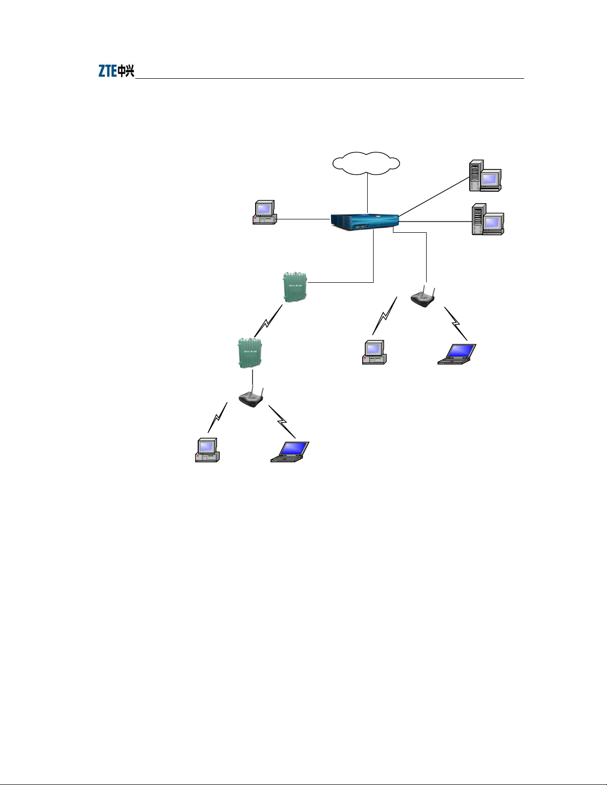
2. Comprising a wireless access network to the Internet together with other
equipment including ACs and bridges.
Internet
AAA
PC
UAS2500E
Ethernet
File server
W110B
W110B
W200A
PC Lop-top computer
Fig. 3.3-2 Comprising a Wireless Access Network to the Internet together with ACs, bridges and
other APs.
PC Lop-top com pute r
W200A
3-5


4 Installation and Debugging
See document “ZXR10 WAS (V1.0) IP Wireless Access System W200A Wireless
Access Point Professional Installation Instruction manual”
4-1


5 Command Line Configurations
This chapter presents the operating procedures of comma nd line configurations and the
commands used.
5.1 Overview
W200A offers Command Line Interfaces (CLIs) for the configurations of all types of
data the W200A uses.
Features of the CLI configurations include:
1. The user can perform either local configurations by using hyperterminal
software via the serial port or local/remote configuration by using Telnet
software via the Ethernet interface or wireless network card.
2. 5 command modes can be used in CLI configuration interfaces: user mode,
privileged mode, configuration mode, Ethernet interface configuration mode and
wireless interface configuration mode. Each mode is the execution environment
of a set of relevant commands. A command can only be executed in its
corresponding command mode. To get the executable commands in the current
mode, type in "?" under this mode.
3. There are two types of commands, information query command and functional
command. information query commands are used to get required information.
Functional commands are used to change configurations of W200A functions.
Changed configurations are saved in the operation configuration database. To
cancel function configurations, execute the reverse command of the original
one (that is, add the no keyword to the front of the original command).
4. The CLI configuration offers a sophisticated help system. You can get relevant
help information by typing "?" at any time.
5. A fuzzy match function is offered for the command input. If the characters you
entered can determine exclusively the command to be executed, you needn't to
input the whole word.
5-1

ZXR10 WAS (V1.0) IP Wireless Access System W200A Wireless Access Point User’s Manual
6. A history function is offered in the CLI configuration interface. You can select a
history command by using the ↑and ↓ keys on the keyboard.
7. A dual password protect is offered in the interfac e to prevent unauthorized users
from accessing. The first password verification appears on the Welcome
interface of the Telnet progra m, where you will enter the user mode for safety
authentication. The default username and password are "root" and "public". You
can enter the privileged mode by inputting "enable" and a correct password in
the user mode. The password for the privileged mode is "zte" by defau lt.
Tips:
When you perform configurations via serial port, no authentication will be needed
because the terminal screen enters user mode directly.
8. The CLI configuration interface supports the automatic paging of command
output on terminals. The "--More--" on the lower left corner of the command
output window indicates there are more output commands. To display the next
page, press the space bar. To exit, press <q>. To output the next line, press the
Enter key.
9. The CLI configuration interface offers a basic command line editing function.
The shortcut key for editing command lines are defined as follows:
Ctrl+U: Delete the whole command being input
Ctrl+A: Move the cursor to the first character of a command line
Ctrl+E: Move the cursor to the last character of a command line
Ctrl+X: Delete all the characters before the cursor
Ctrl+K: Delete all the characters after the cursor (including the character where
the cursor is)
Ctrl+C: Abandon all input. A new line and a new prompt appear.
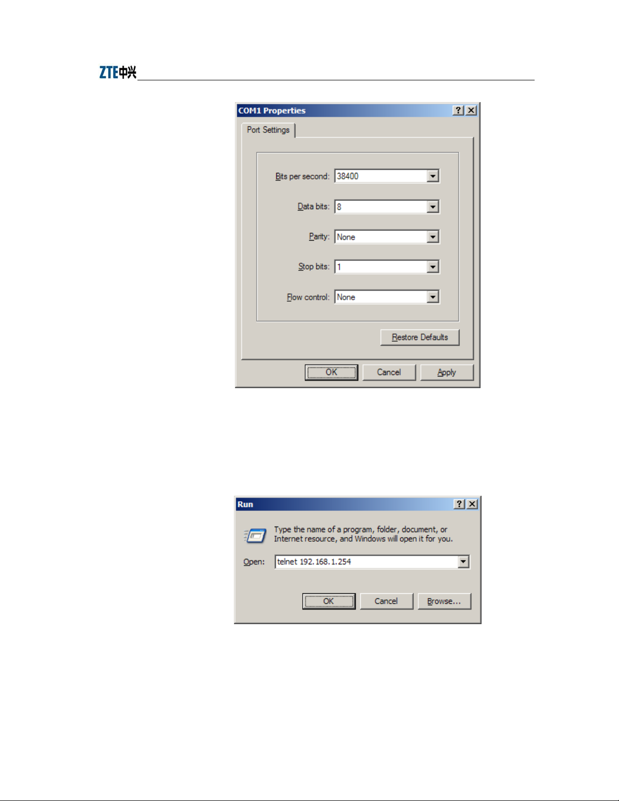
To configure the W200A via the serial port, set the serial port attributes of the
hyperterminal as shown in Fig. 5.1-1.
5-2
Chapter Error! Style not defined. Error! Style not defined.
Fig. 5.1-1 Serial Port Configuration
To configure the W200A vi a Telnet, input telnet/operating IP address of the W200A, as
shown in Fig. 5.1-2. By default, the operating IP address of the W200A is
192.168.1.254 and the subnet mask is 255.255.255.0.
Fig. 5.1-2 Telnet to W200A
The 5 configuration modes for W200A and all the executable commands in each mode
are described in details as follows. In the following text, conventions are given as
5-3

ZXR10 WAS (V1.0) IP Wireless Access System W200A Wireless Access Point User’s Manual
follows to the expression of commands:
1. abc denotes the contents that you should enter.
2. {abc|def} denotes that you must type in one of the two options.
3. The number range with [A~B] denotes you can type in a configuration
parameter within this range.
4. [ ] denotes that you can either enter the contents in [ ] or not.
5.2 User Mode
Mode of entry: Telnet
Exit mode: exit
Default prompt: wlan>
Note: When an ordinary user logs in to the W200A via Telnet, he/she will not be able to
enter the user mode unless he/she passes the username and password authentication. By
default, the username and password are "root" and "public". To prevent illegal users
from attempting the password frequently, the system will cut the Telnet connections of
a user automatically if incorrect passwords has been entered 3 times continuously.
5.3 Privileged Mode
Mode of entry: Type in the enable command in the in use mode and enter the correct
password.
Exit mode: disable for entering the user mode; exit for ex iting the privilege d mode and
go back to the system.
Default prompt: wlan#
5.3.1 Command to Test Network Connectivity
Command mode: privileged mode
Function: Test the network connectivity
Command format: wlan#ping A.B.C.D [-n echo-number] [-w timeout] [-l packet-size]
5-4
 Loading...