

Page 1

ZXR10 WAS (V1.0) IP Wireless Access System
W140A Outdoor Wi reless Access
Point/Bridge
User’s Manual
ZTE CORPORATION
Page 2

ZXR10 WAS (V1.0) IP Wir eless Access System
W140A Outdoor Wireless Access Point/Bridge
User’s Manual
Manual Version 20040325-R1.0
Product Version V1.0
Copyright © 2003 ZTE Corporation
All rights reserved.
No part of this documentation may be excerpted, reproduced, translated, annotated or
duplicated, in any form or by any means without the prior written permission of ZTE
Corporation.
ZTE CORPORATION
ZTE Plaza, Keji Road South, Hi-Tech Industrial Park, Nanshan District, Shenzhen, P.R.China
Website: http://www.zte.com.cn
Postcode: 518057
Customer Support Center: (+86755) 26771900 800-9830-9830
Fax: (+86755) 26770801
Email: support@zte.com.cn
* * * *
S.N.: sjzl20040367
Page 3

FAX:+86-755-26770160
Suggestions and Feedback
To improve the quality of ZTE product documentation and offer better services to our customers, we hope
you can give us your suggestions and comments on our documentation and fax this form to
rd
+86-755-26770160; or mail to “Marketing center 3
Park, Nanshan District, Shenzhen, P. R. China”. Our postcode is 518057.
floor ZTE Plaza, Keji Road South, Hi-Tech Industrial
Document name
Product version
Equipment installation time
Your information
Name
Postcode
Telephone
Your evaluation
of this
documentation
ZXR10 WAS (V1.0) IP Wireless Access System W140A Outdoor Wireless Access Point/Bridge
User’s Manual
V1.0
Presentation: How is information presented? (Introductions, procedures, illustrations, others)
□
Good □ Fair □Average □ Poor □Bad
Accessibility: Can you find the information you want? (Table of contents, Index, headings,
numbering, others)
□ Good □ Fair □Average □ Poor □Bad
Intelligibility: Can you understand it when you find it? (Language, vocabulary, readability, others)
□
Good □ Fair □Average □ Poor □Bad
Presentation:
Document version 20040325-R1.0
Company
Company address
E-mail
Your suggestions
for improvement
of this
documentation
Your other
suggestions on
ZTE product
documentation
Accessibility:
Intelligibility:
Page 4

Page 5

Preface
About This Manual
This manual is applicable to the ZXR10 WAS (V1.0) IP Wireless Access System
W140A Outdoor Wireless Access Point/Bridge (W140A for short below).
The ZXR10 WAS IP wireless access system is a proprietary product of ZTE
Corporation. It consists of a series of wireless access network products, such as
wireless network card, wireless Access Point (AP), wireless router, DSL 2-in-1 wireless
router and outdoor wireless access point/bridge.
This manual introduces the function features, installation, operation, use and
maintenance of the W140A, so it serves as instructions to the W140A. This manual
consists of 6 chapters and 2 appendixes.
Chapter 1, Safety Precautions, introduces the safety precautions of this product and
safety symbols used in this manual.
Chapter 2, Overview, presents functions, features and technical parameters of the
W140A.
Chapter 3, Structure and Principle, describes structure and principle of W140A.
Chapter 4, Installation and Debugging, deals with the installation and debugging
methods of the W140A.
Chapter 5, Command Line Configuration, covers the command line configurations of
the W140A.
Chapter 6: WEB configuration, presents the web configurations of W140A.
Chapter 7, Maintenance, puts forward the daily maintenance and version upgrade
methods of the W140A.
Appendix A, Packing, Transportation and Storage, outlines the packaging method,
storage conditions and transportation precautions of the W140A.
Appendix B, Making of Ethernet cables, introduces the power supply mode of W140A
Ethernet and making of Ethernet cables.
Conventions
Page 6

Four striking symbols are used throughout this manual to emphasize important and
critical information during operation:
Danger, Warnin g, Caution and Note statements are
used throughout this manual to emphasize important and critical information. You must
read these statements to help ensure safety and to prevent product damage. The
statements are defined below.
Statement: The actual product may differ from what is described in this
manual due to frequent update of ZTE products and fast development of
technologies. Please contact the local ZTE office for the latest updating
information of the product.
Page 7

Contents
1 Safety Precautions...................................................................................................................................1-1
1.1 Safety Precautions..........................................................................................................................1-1
1.2 Symbol Description........................................................................................................................1-2
2 Overview..................................................................................................................................................2-1
2.1 Preface............................................................................................................................................2-1
2.2 Functions and Features...................................................................................................................2-1
2.3 Technical Characteristics and Parameters ......................................................................................2-2
3 Structure and Principle...........................................................................................................................3-1
3.1 Structure and Working Principle .................................................................................................... 3-1
3.1.1 Hardware Structure .............................................................................................................3-1
3.1.2 Software Structure...............................................................................................................3-1
3.2 Units/Components..........................................................................................................................3-2
3.3 Networking Modes.........................................................................................................................3-3
4 Installation and Debugging ....................................................................................................................4-1
5 Command Line Configuration...............................................................................................................5-1
5.1 Overview........................................................................................................................................ 5-1
5.2 User Mode...................................................................................................................................... 5-3
5.3 Privileged Mode ............................................................................................................................. 5-4
5.3.1 Command to Test Network Connectivity............................................................................ 5-4
5.3.2 Command to Save Configurations to Flash.........................................................................5-4
5.3.3 Command to Reset Software...............................................................................................5-4
5.3.4 Command to Enter Configure Mode...................................................................................5-5
5.3.5 Command to Exit Privileged Mode..................................................................................... 5-5
-i-
Page 8

5.3.6 Command to Exit TELNET Configuration......................................................................... 5-5
5.4 Configure Mode............................................................................................................................. 5-5
5.4.1 Commands to Configure Wireless Access-Bridge.............................................................. 5-5
5.4.2 Command to Configure Bridge Information....................................................................... 5-6
5.4.3 Commands to Configure DHCP Server .............................................................................. 5-7
5.4.4 Discover commands............................................................................................................ 5-8
5.4.5 Commands to Configure 802.1X Parameters ..................................................................... 5-9
5.4.6 Command to Set User Password in Privileged Mode ....................................................... 5-12
5.4.7 Command to Delete Filtration Rules ................................................................................ 5-12
5.4.8 Command to Exit Configuration Mode ............................................................................ 5-13
5.4.9 Commands to Configure IAPP (Load-balance) ................................................................ 5-13
5.4.10 Interface Skip.................................................................................................................. 5-14
5.4.11 Commands to Configure Layer 2 Isolation..................................................................... 5-15
5.4.12 Commands to Configure IP network Parameters............................................................ 5-15
5.4.13 Command to Configure Log Print Information .............................................................. 5-16
5.4.14 Command to Configure MAC Filter............................................................................... 5-17
5.4.15 Command to Configure MAC Address Authentication.................................................. 5-18
5.4.16 Command to Configure Users ........................................................................................ 5-18
5.4.17 Commands to Configure Radius Server ......................................................................... 5-19
5.4.18 Command to Configure SNMP Module ......................................................................... 5-21
5.4.19 Command to Manage Telnet Idle Timeout ..................................................................... 5-25
5.4.20 Commands to Upload/download TFTP Files.................................................................. 5-25
5.4.21 Commands to Configure VLAN ..................................................................................... 5-26
5.4.22 Show Commands ............................................................................................................5-27
5.5 Ethernet Interface Configuration Mode .......................................................................................5-33
5.5.1 Configurations in the Ethernet Interface Mode................................................................. 5-33
-ii-
Page 9

5.5.2 Command to Exit the Ethernet Interface Configuration Mode ......................................... 5-33
5.5.3 Command to Configure Ethernet interface IP addresses...................................................5-33
5.5.4 Command to Configure MAC filter for the Ethernet Interface......................................... 5-34
5.6 Wireless Interface Configuration Mode .......................................................................................5-34
5.6.1 Command to Configure 80211b-related Parameters for the Wireless Interface................5-34
5.6.2 Command to Exit Wireless Interface Configuration Mode...............................................5-36
5.6.3 Command to Enable Link Integrity Detection .................................................................. 5-37
5.6.4 WEP Configuration of the Wireless Interface ...................................................................5-37
5.6.5 Command to Configure MAC Filter in Wireless Interface Configuration........................ 5-38
5.6.6 Command to Configure Authentication Mode in Wireless Interface Configuration.........5-39
6 WEB Configuration ................................................................................................................................6-1
6.1 Overview........................................................................................................................................ 6-1
6.2 Opening the login WEB page......................................................................................................... 6-2
6.3 Main menu of WEB configuration................................................................................................. 6-4
6.3.1 Home page (basic product information)..............................................................................6-4
6.3.2 Stations page ....................................................................................................................... 6-5
6.3.3 Statistics Page...................................................................................................................... 6-6
6.3.4 Load Balance page .............................................................................................................. 6-6
6.3.5 SNMP page ......................................................................................................................... 6-7
6.3.6 Security page..................................................................................................................... 6-12
6.3.7 Save page .......................................................................................................................... 6-15
6.3.8 Reboot page.......................................................................................................................6-15
6.3.9 Advanced options page .....................................................................................................6-16
6.3.10 Accounts page .................................................................................................................6-23
6.4 Interfaces page ............................................................................................................................. 6-23
6.4.1 Ethernet Interface page .....................................................................................................6-24
-iii-
Page 10

6.4.2 Wireless Interface page..................................................................................................... 6-25
6.5 Data submission flow for WEB configuration............................................................................. 6-27
7 Maintenance............................................................................................................................................7-1
7.1 Maintenance Descriptions ............................................................................................................. 7-1
7.2 Daily Maintenance......................................................................................................................... 7-2
7.3 Version Loading and Upgrade ....................................................................................................... 7-2
7.3.1 TFTP File Loading Commands........................................................................................... 7-3
Appendix A Package, Transportation and Storage................................................................................ A-1
A.1 Package ........................................................................................................................................ A-1
A.2 Transportation.............................................................................................................................. A-1
A.3 Storage ......................................................................................................................................... A-2
Appendix B Making of Ethernet Cable ...................................................................................................B-1
B.1 W140A System Application Modes..............................................................................................B-1
B.2 Making of Ethernet Cables ...........................................................................................................B-2
B.2.1 Making of Straight Through Ethernet Cables (RJ45).........................................................B-2
B.2.2 Making of Straight Through Power Supply Ethernet Cables (C-RJ45-001)......................B-2
B.2.3 Making of Crossover Ethernet Cables (RJ45J) ..................................................................B-3
B.2.4 Ethernet Cable Label..........................................................................................................B-4
-iv-
Page 11

A List of Figures
Fig. 3.1-1 Appearance of W140A .....................................................................................................3-1
Fig. 3.1-2 W140A Software Structure...............................................................................................3-2
Fig. 3.2-1 W140A Rear Control Panel ..............................................................................................3-2
Fig. 3.3-1 Building Small Wireless LAN ..........................................................................................3-3
Fig. 3.3-2 Building Internet Wireless Access Network with AC, Indoor AP and Outdoor Bridge....3-4
Fig. 3.3-3 Wireless Bridge Mode ...................................................................................................... 3-5
Fig. 4.1-1 Telnet to W140A ..............................................................................................................5-3
Fig. 5.1-1 Path diagram of WEB configuration ................................................................................6-2
Fig. 5.2-1 Login page for WEB configuration ..................................................................................6-3
Fig. 5.2-2 Alert box for prompting that someone has already logged in for WEB configuration..... 6-3
Fig. 5.2-3 Alert box for prompting that the entered user name and password are incorrect.............6-4
Fig. 5.3-1 Home page (basic product information) ...........................................................................6-5
Fig. 5.3-2 Stations page.....................................................................................................................6-5
Fig. 5.3-3 Statistics page ...................................................................................................................6-6
Fig. 5.3-4 Load Balance page ...........................................................................................................6-7
Fig. 5.3-5 Submenu for SNMP configuration ................................................................................... 6-8
Fig. 5.3-6 Access mode configuration page of the SNMP module...................................................6-8
Fig. 5.3-7 Access host configuration page of the SNMP module .....................................................6-9
Fig. 5.3-8 Community configuration page of the SNMP module ...................................................6-10
Fig. 5.3-9 System information configuration page of the SNMP module.......................................6-10
Fig. 5.3-10 Trap configuration page of the SNMP module............................................................. 6-11
Fig. 5.3-11 Trap sink configuration page of the SNMP module .....................................................6-12
Fig. 5.3-12 Submenu of security configuration............................................................................... 6-12
-i-
Page 12

Fig. 5.3-13 MAC authentication configuration page...................................................................... 6-13
Fig. 5.3-14 MAC filter rule configuration page.............................................................................. 6-14
Fig. 5.3-15 Stations Isolation page ................................................................................................. 6-14
Fig. 5.3-16 Save page ..................................................................................................................... 6-15
Fig. 5.3-17 Reboot page.................................................................................................................. 6-16
Fig. 5.3-18 Submenu of advanced options configuration ............................................................... 6-16
Fig. 5.3-19 Submenu of DHCP module.......................................................................................... 6-17
Fig. 5.3-20 DHCP server configuration page ................................................................................. 6-17
Fig. 5.3-21 IP pool page.................................................................................................................. 6-18
Fig. 5.3-22 802.11x configuration page.......................................................................................... 6-19
Fig. 5.3-23 Submenu of RADIUS server configuration ................................................................. 6-19
Fig. 5.3-24 ISP configuration page ................................................................................................. 6-20
Fig. 5.3-25 Authentication Server configuration page.................................................................... 6-21
Fig. 5.3-26 Accounting Server configuration page......................................................................... 6-21
Fig. 5.3-27 DNS configuration page............................................................................................... 6-22
Fig. 5.3-28 VLAN configuration Page ........................................................................................... 6-22
Fig. 5.3-29 Account configuration page .........................................................................................6-23
Fig. 5.4-1 Submenu for interface configuration.............................................................................. 6-23
Fig. 5.4-2 Submenu for Ethernet interface configuration............................................................... 6-24
Fig. 5.4-3 IP address configuration page of Ethernet interface....................................................... 6-24
Fig. 5.4-4 Submenu for wireless interface configuration ............................................................... 6-25
Fig. 5.4-5 802.11b parameter configuration page of wireless interface.......................................... 6-25
Fig. 5.4-6 WEP configuration page of wireless interface ............................................................... 6-26
Fig. 5.4-7 Link integrity configuration page of wireless interface ................................................. 6-27
Fig. 5.5-1 The page for entering the password of privileged user .................................................. 6-28
Fig. 5.5-2 The page indicating that the privileged user password is incorrect................................ 6-28
-ii-
Page 13

Fig. 5.5-3 A message indicating successful data submission ..........................................................6-29
Fig. 5.5-4 A message indicating failure in data submission ............................................................ 6-29
Figure B.1-1 W140A System Application........................................................................................ B-1
Figure B.2-1 Straight through Ethernet label ...................................................................................B-4
Figure B.2-2 Label of the Straight Through Power Supply Ethernet Cable..................................... B-4
Figure B.2-3 Crossover Ethernet Cable Label ................................................................................. B-5
-iii-
Page 14

Page 15

A list of Tables
Table 1.2-1 Safety Symbols and Descriptions................................................................................... 1-3
Table 2.3-1 W140A Technical Indices .............................................................................................. 2-3
Table B.2-1 Connections of Straight Through Ethernet Cables (RJ45) ........................................... B-2
Table B.2-2 Connections of Straight Through Power Supply Ethernet Cables (C-RJ45-001)......... B-3
Table B.2-3 Connections of Crossover Ethernet Cables (RJ45J)..................................................... B-3
-i-
Page 16

Page 17

1 Safety Precautions
This chapter introduces the safety precautions of this product and safety symbols used
in this manual.
1.1 Safety Precautions
This device complies with Part 15 of the FCC Rules. Operation is subject to the
following two conditions: (1)This device may not cause harmful interference,and
(2)
this device must accept any interference received, including interference that
may cause undesired operation.
To assure continued compliance, (example – use only shielded interface cables when
connecting to computer or peripheral devices). Any changes or modifications not
expressly approved by the party responsible for compliance could void the user’s
authority to operate the equipment.
NOTE: This equipment has been tested and found to comply with the limits for a Class
B digital device, pursuant to Part 15 of the FCC Rules. These limits are designed to
provide reasonable protection against harmful interference in a residential installation.
This equipment generates, uses and can radiate radio frequency energy and, if not
installed and used in accordance with the instructions, may cause harmful interference
to radio communications. However, there is no guarantee that interference will not
occur in a particular installation. If this equipment does cause harmful interference to
radio or television reception, which can be determined by turning the equipment off
and on, the user is encouraged to try to correct the interference by one of the following
measures:
- Reorient or relocate the receiving antenna.
- Increase the separation between the equipment and receiver.
- Connect the equipment into an outlet on a circuit different from that to which the
receiver is connected.
- Consult the dealer or an experienced radio/TV technician for help.
This equipment is with high temperature and voltage, so only the professional
1-1
Page 18

ZXR10 WAS (V1.0) W140A Outdoor Wireless Access Point / Bridge User’s Manual
personnel who had passed the training can install, operate and maintain it.
ZTE assumes no responsibility for consequences resulting from violation of general
specifications for safety operations or of safety rules for design, production and use of
equipment.
1.2 Symbol Description
See Table 1.2-1 for the safety symbols used in this manual, which serves to remind the
readers of the safety precautions to be taken when the equipment is installed, operated
and maintained.
1-2
Page 19
Chapter Error! Style not defined. Error! Style not defined.
Table 1.2-1 Safety Symbols and Descriptions
Safety Symbol Meaning
Call for notice
Call for antistatic measures
Warn against electric shock
Caution against scald
Warn against laser
Caution against microwave
Four types of safety levels are available: danger, warning, caution and note. To the
right of a safety symbol is the text description of its safety level. Under the symbol is
the detailed description about its contents. The formats are as follows.
Danger:
Indicates an imminently hazardous situation which, if not avoided, will result in death
or serious injury. This signal word is to be limited to the most extreme situations.
Warning:
Indicates a potentially hazardous situation which, if not avoided, could result in death
or serious injury.
Caution:
Indicates a potentially hazardous situation which, if not avoided, could result in minor
or moderate injury. It may also be used to alert against unsafe practices.
1-3
Page 20

ZXR10 WAS (V1.0) W140A Outdoor Wireless Access Point / Bridge User’s Manual
Note:
A Note statement is used to notify people of installation, operation, or maintenance
information that is important, but not hazard-related.
Tips:
Indicates a suggestion or hint to make things easier or more productive for the reader
1-4
Page 21

2 Overview
This chapter presents functions, features, technical characteristics and parameters of
the W140A.
2.1 Preface
The W140A outdoor AP/bridge of ZXR10 WAS (V1.0) IP wireless access system is
developed by ZTE and its design totally complies with the international standards.
The W140A uses customized antennas on the roof or a special pole for wide coverage,
enabling wireless cellular roaming in a large area.
2.2 Functions and Features
W140A complies with IEEE 802.11b Standard and is compatible with wireless network
adapters and APs complying with this standard. The features of the W140A are as
follows:
● The maximum access rate is 11 Mbps. At most 100 Stations can be accessed.
● The radio transmission power can be adjusted up to 200 mW.
● Transparent bridge connection provides packet transfer between Basic Service
Set (BSS) and Distributed System (DS). The maximum transfer rate is not less
than 10 Mbps.
● The load balance adopts the access balance with multiple APs in the same area
provided by the internal protocol.
● It provides seamless roaming to enable users to access network easily.
● It provides link integrity function, thus enhancing equipment reliability.
● ESSID provides network authentication to prevent illegal users from accessing
the network.
● Static MAC filtration can filter MAC addresses set by users. Up to 100 filtration
groups can be set and each of them can be set with 64 MAC address filtration
rules.
2-1
Page 22

ZXR10 WAS (V1.0) W140A Outdoor Wireless Access Point / Bridge User’s Manual
● It provides data authentication and security management, supports 64-bit and
128-bit WEP encryption, provides mixed encryption for more flexible security.
● Automatic consistent correction system provides Automatic Scale Back
Functionality (ASBF) to automatically correct WLAN to the best connection
quality.
● High interoperability: the uplink interface is 10/100M adaptive Ethernet
interface, which can be connected through a network cable to the 10/100 Mbps
Ethernet in compliance with IEEE 802.3 network protocol.
● The uplink Ethernet interface provides VLAN trunk function, wireless access
users can be grouped into VLAN through MAC addresses, and W140As can be
grouped under the management VLAN.
● The version upgrade function upgrades the W140A software version and
supports remote online version loading.
● The embedded SNMP Agent supports SNMP v1/v2 to implement MIB II,
IEEE802dot11-MIB, IF-MIB, EtherLike-MIB and private MIB.
● Command line and WEB configuration modes are available for W140A
configuration, supporting remote uploading and downloading of configuration
files.
● Integrated management server is provided to monitor and manage ZTE wireless
network equipment, including W140A, in the distributed environment.
● The reliability design complies with IEC 60529 Standard, waterproof
performance reaches level 8, and dustproof performance reaches level 6.
● There is a dedicated lightning protection board the input terminal. For the
Ethernet part, the lightning strike surge tolerance is 2 kV between line and
ground and 1 kV between line and line. For the power supply part, the surge
tolerance should be 4 kV between line and ground and 2 kV between line and
line.
2.3 Technical Characteristics and Parameters
The technical indices of W140A are shown in Table 2.3-1.
2-2
Page 23

Chapter Error! Style not defined. Error! Style not defined.
Table 2.3-1 W140A Technical Indices
Items Technical Indices
Standard 802.11b, 802.1d, 802.3u
Working band 2,400 MHz ~ 2,483.5 MHz
Spreading mode DSSS
Modulation mode CCK, DQPSK, DBPSK
BER ≤10-5
Data rate Adaptive 1 Mbps, 2 Mbps, 5.5 Mbps and 11 Mbps
Distance (m)
External interfaces RJ45 connector and wireless interface
Encryption type 64/128-bit WEP encryption
Channel quantity EU countries, 13; US and Canada: 11; France: 4; Japan: 14
Recommended number of users/maximum
number of users
MAC address capacity 1024
SNMP agent
Antenna System
Power supply mode
Total power consumption < 10 W
Dimensions 360 mm × 300 mm × 80 mm (L × W × H)
Weight 6 kg
Working temperature: -35 °C ~ +60 °C
Storage temperature -40 °C ~ +70 °C
Working humidity 5% ~ 95%
Storage humidity 10% ~ 100%
Outdoor AP and 100 m~700 m;
Outdoor bridge, 25 km at the farthest
30/100
Supporting SNMP v1/v2, implementing MIB II, IEEE802dot11-MIB,
IF-MIB, EtherLike-MIB and private MIB
Outdoor AP: 8 dBi omni-directional, 8.5 dBi directional and 14 dBi
directional are available;
Outdoor bridge: 8 dBi omni-directional, 8.5 dBi directional, 14 dBi
directional and 21 dBi directional are available
PoE 48V Ethernet power supply. The remote supply distance is 100m when
the Ethernet interface works at 100 Mbps, and the distance is 280m when the
Ethernet interface works at 10 Mbps
2-3
Page 24

Page 25
3 Structure and Principle
This chapter introduces the structure and principle of W140A, covering software and
hardware structure and principle, interfaces and networking modes.
3.1 Structure and Working Principle
3.1.1 Hardware Structure
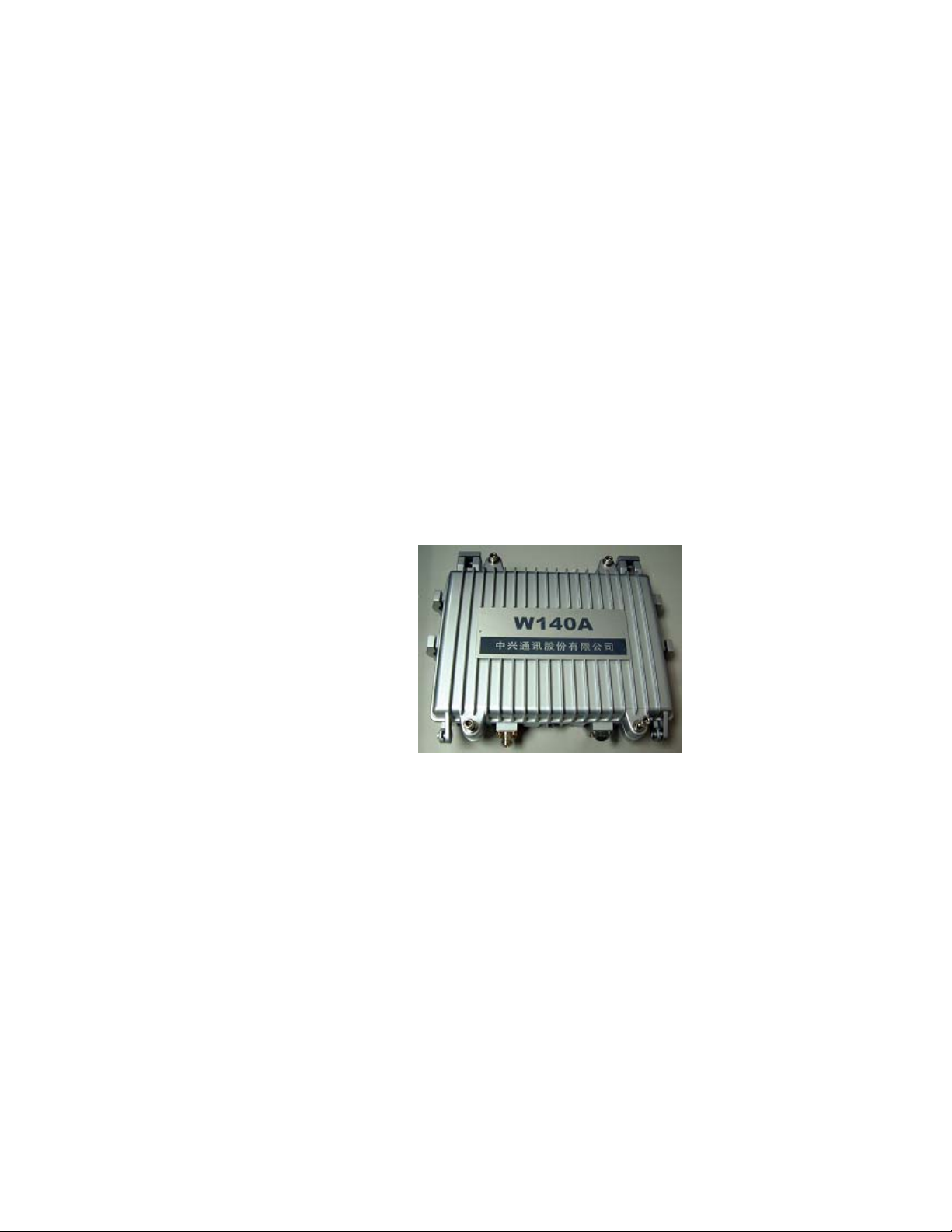
With a standard waterproof and dustproof structure, W140A can be installed on the
roof, outside the window or on a special pole. The physical appearance of W140A is
shown in Fig. 3.1-1.
CPU is the core of W140A, and its memory may be 512K BOOT, 4M FLASH and
16M SDRAM.
3.1.2 Software Structure
The software function structure of W140A is given in Fig. 3.1-2.
Fig. 3.1-1 Appearance of W140A
3-1
Page 26
ZXR10 WAS (V1.0) W140A Outdoor Wireless Access Point / Bridge User’s Manual
RADIUS Client
DHCP Server
TFTP
IAPP
SNMP
TCP/UDP
IP
802.1x STP Other L2 protocol
Layer-2 supporting system
DB
R01
802.11 driver RS232 driver Ethernet driver BSP
Fig. 3.1-2 W140A Software Structure
HTTP
TELNET
Security system
OMS
The software of W140A comprises the basic service subsystem and network
management subsystem.
● The basic service subsystem consists of these items: 802.11b AP drive, 802.3
Ethernet drive, transparent bridge connection, load balance, TCP/IP protocol
stack, dynamic address distribution, static MAC address filtration, and VLAN.
● The network management subsystem consists of SNMP Agent, telnet command
line configuration module, WEB page configuration module, and GUI integrated
management module.
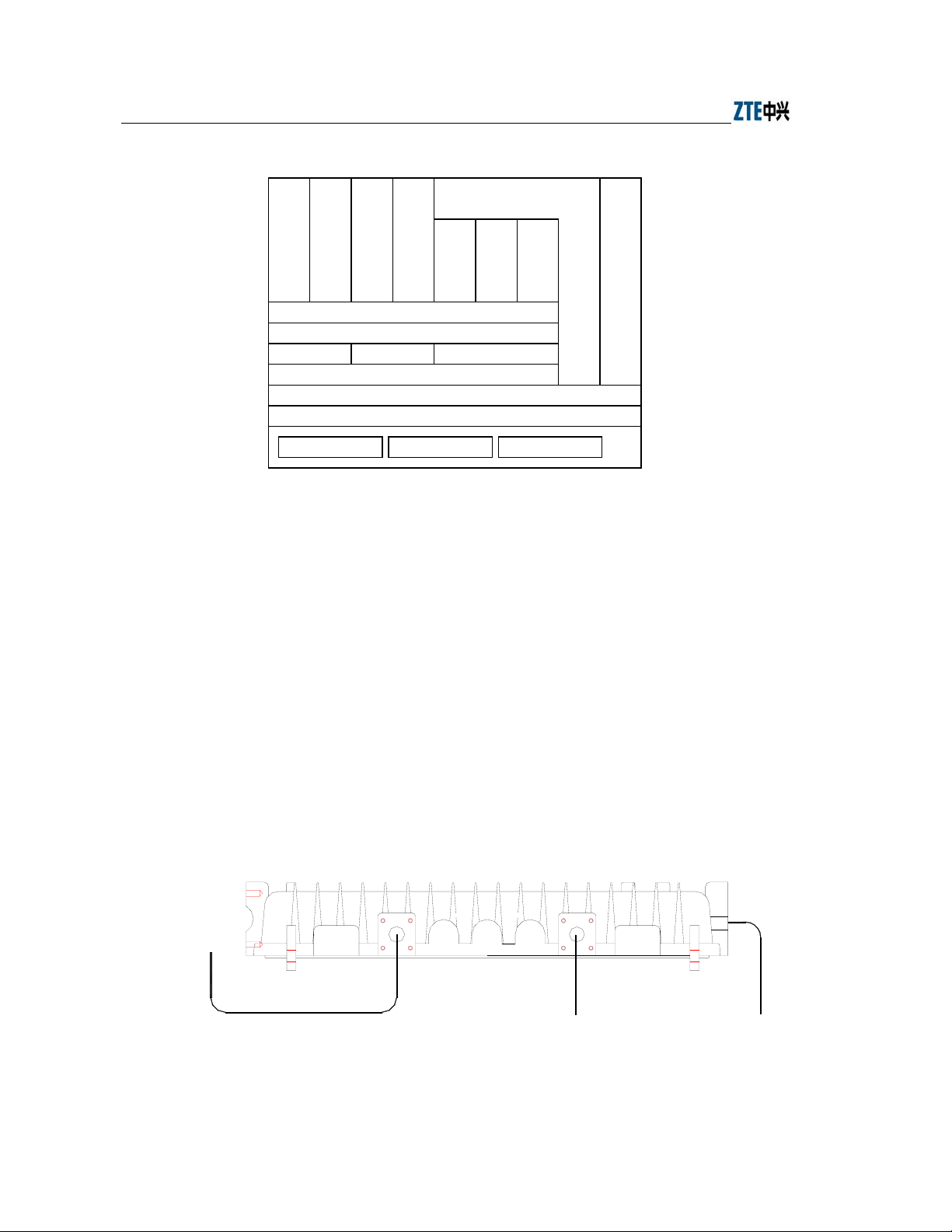
3.2 Units/Components
W140A Rear Control Panel is shown in Fig. 3.2-1
To
antenna
12
Ethernet cable and feeder To the ground
Fig. 3.2-1 W140A Rear Control Panel
3-2
Page 27
The interfaces on the rear control panel are described as follows:
1. Chassis transfer interface 1: Ethernet
2. Chassis transfer interface 2: Antenna interface for antenna installation
3. Chassis grounding interface
3.3 Networking Modes
W140A provides both outdoor wireless access and Wi-Fi bridge function. The
operation modes of W140A are as follows.
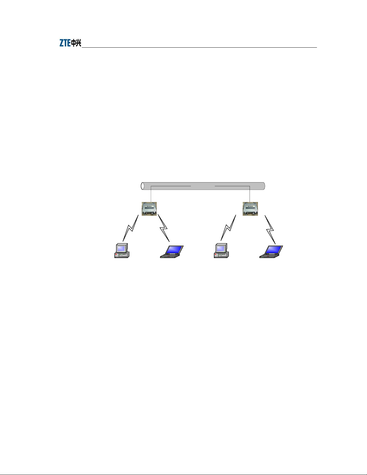
1. Building small wireless LAN
Chapter Error! Style not defined. Error! Style not defined.
Wired LAN
W140A W140A
PC Lap-top Computer PC Lap-top Computer
Fig. 3.3-1 Building Small Wireless LAN
3-3
Page 28
ZXR10 WAS (V1.0) W140A Outdoor Wireless Access Point / Bridge User’s Manual
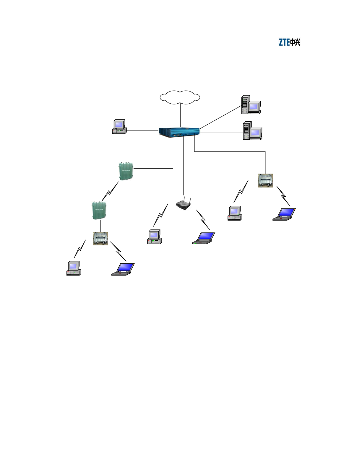
2. Building Internet wireless access network together with AC, indoor AP and
outdoor bridge.
Internet
PC
W110B
W110B
W140A
PC Lap-top Computer
UAS2500E
Ethernet
W200A
PC Lap-top Computer
AAA
File server
W140A
PC Lap-top Computer
Fig. 3.3-2 Building Internet Wireless Access Network with AC, Indoor AP and Outdoor Bridge
3. Implementing bridge function
If two areas are far from each other or there are some obstacles between them,
W140A can be used for bridging. as shown Fig. 3.3-3, the two W140As work in
Bridge Server and Bridge Client modes respectively to provide a wireless bridge
between LAN1 and LAN2. The bandwidth of the bridge is decided by the
Bridge server. The Bridge Server may serve several Bridge Clients at the same
time. Considering the performance of wireless connection, Bridge server had
better not serve more than four Bridge clients.
3-4
Page 29

Chapter Error! Style not defined. Error! Style not defined.
Bridge
Server
Bridge
Client
LAN1
Bridge
Client
LAN2
Fig. 3.3-3 Wireless Bridge Mode
3-5
Page 30

Page 31

4 Installation and Debugging
See document “ZXR10 WAS (V1.0) IP Wireless Access System W140A Outdoor
Wireless Access Point/Bridge Professional Installation Instruction manual”
4-1
Page 32

Page 33

5 Command Line Configuration
This chapter describes the operation methods and configuration commands of the
W140A command line configuration.
5.1 Overview
The W140A provides the Command Line Interface (CLI) for configuring the W140A
data.
The CLI configuration of the W140A has the following features:
1. The CLI configuration of the W140A allows users to perform configuration
through the Ethernet interface and wireless network card in the Telnet mode.
2. The CLI provides five command modes: User, privileged, configure, Ethernet
interface configuration and wireless interface configuration modes One mode is
the execution environment of a group of related commands, and one command
can be executed only in the corresponding command mode. To obtain the valid
commands in the current command mode, just input “?” in the current mode.
3. Commands are divided into information query command and function command.
The information query command serves to obtain some information to be
queried. The function command serves to change the function configuration of
the W140A. The changed configuration is saved in the running configuration
information library. To cancel the function configuration, execute the reverse
command of the former command (that is, no + key word + original command)
4. The CLI provides perfect help system: At any time, you can input “?” to obtain
the related help information.
5. The command inputting provides the fuzzy match function: Once the
information input by the user is enough for determining a command, it is not
necessary to input the full spell.
6. The CLI provides the command history function: You can select a historical
command for executing through “↑” or “↓” of the keyboard.
5-1
Page 34

ZXR10 WAS (V1.0) W140A Outdoor Wireless Access Point / Bridge User’s Manual
7. The CLI provides two layers of password protection to reject illegal users. The
first layer password authentication appears on the Telnet welcome interface, then
the safety authentication for accessing the user mode is required. The default
user name is “root” and default password is “public”. In the user mode, input the
enable command and correct password to enter the privileged mode, the default
password is “zte”.
8. The CLI can automatically page the output commands on the terminal:
“—More—” at the lower left corner of the command output window indicates
more output commands. At this time, you can press CTRL to display the next
page, press ENTER to output the next line and press other keys to exit.
9. The W140A CLI provides the basic command line editing function. The
short-cut keys for editing command lines are described as follows:
Ctrl + U: Delete the whole command being input.
Ctrl + A: Move the cursor to the first character of the command line.
Ctrl + E: Move the cursor to the last character of the command line.
Ctrl + X: Delete all the characters before the cursor.
Ctrl + K: Delete all the characters after the cursor (containing the character at
the cursor)
Ctrl + C: Give up all the input contents. Enter the new line and the prompt
character will appear.
When the Telnet mode is used for configuring the W140A, you just need to input
“telnet working IP address of W140A”, as shown in Fig. 5.1-1. By default, the W140A
working IP address is 192.168.1.254 and the sub-network mask is 255.255.255.0.
5-2
Page 35

Chapter Error! Style not defined. Error! Style not defined.
Fig. 5.1-1 Telnet to W140A
These five configuration modes of the W140A and all the available commands under
each mode are described in detail as follows: The stipulation of command format is as
follows:
1. The abc
2. The {abc | def} means that the user should input either of the two items.
3. [A ~ B] indicates the digital range of the configuration parameters that the user
4. For the contents included in [ ], the user can choose to input or not input them..
5.2 User Mode
Mode of entry: Telnet
Exit mode: exit
Default prompt: wlan>
Note: When an ordinary user logs in to the W140A via Telnet, he/she will not be able to
enter the user mode unless he/she passes the username and password authentication. By
default, the username and password are "root" and "public". To prevent illegal users
from attempting the password frequently, the system will cut the Telnet connections of
a user automatically if incorrect passwords have been entered 3 times continuously.
refers to the contents to be input by the user.
can input.
5-3
Page 36

ZXR10 WAS (V1.0) W140A Outdoor Wireless Access Point / Bridge User’s Manual
5.3 Privileged Mode
Mode of entry: Type in the enable command in the in use mode and enter the correct
password.
Exit mode: disable for entering the user mode; exit for exiting the privileged mode and
go back to the system.
Default prompt: wlan#
5.3.1 Command to Test Network Connectivity
Command mode: privileged mode
Function: Test the network connectivity
Command format: ping A.B.C.D [-n echo-number] [-w timeout] [-l packet-size]
Parameter description:
Name Range Description
A.B.C.D
-n Null Sets the flag bits for the number of PING packets
echo-number
-w Null Sets the flag bits for the maximum timeout interval
Timeout
-l Null Sets the flag bits for the capacity of buffer area
packet-size
IP address
1~40
1~2
0~1504
Destination IP address
The number of PING packets
Maximum timeout interval (unit: s)
Capacity of buffer area
5.3.2 Command to Save Configurations to Flash
Command mode: privileged mode
Function: Save configurations to flash
Command format: wlan#write flash
5.3.3 Command to Reset Software
Command mode: privileged mode
Function: Reset W140A
Command format: wlan#reboot
5-4
Page 37

Chapter Error! Style not defined. Error! Style not defined.
5.3.4 Command to Enter Configure Mode
Command mode: privileged mode
Function: Enter configuration modes
Command format: wlan#configure terminal
5.3.5 Command to Exit Privileged Mode
Command mode: privileged mode
Function: Exit Privileged Mode and enter User Mode
Command format: wlan#disable
5.3.6 Command to Exit TELNET Configuration
Command mode: privileged mode
Function: Exit Telnet and go back to the system
Command format: wlan#exit
Note: This command can only be used via Telnet. If you log in by using a
hyperterminal mode via the serial port, this command will not be available.
5.4 Configure Mode
Mode of entry: Enter the configure terminal command in Privileged Mode
Exit mode: Exit and enter privileged mode
Default prompt: wlan (config) #
Note: In this mode (including the sub-mode), all the configuration commands can be
executed.
5.4.1 Commands to Configure Wireless Access-Bridge
1. access-bridge client connect-server
Command mode: Configure mode
Function: Configure the MAC address of the access bridge connecting the server
Command format: wlan (config) #access-bridge client connect-server mac
5-5
Page 38

ZXR10 WAS (V1.0) W140A Outdoor Wireless Access Point / Bridge User’s Manual
Parameter description:
Name Range Description
mac
MAC address in the
xx-xx-xx-xx-xx-xx format
MAC address of the access bridge connecting
the server
2. access-bridge client enable
Command mode: Configure mode
Function: Enable/disable the wireless bridge client
Command format: wlan( config) #[no] access-bridge client enable
3. access-bridge server connect-client
Command mode: Configure mode
Function: Configure the MAC address of the access bridge connecting clients
Command format: wlan(config)#[no] access-bridge server connect-client mac
Parameter description:
Name Range Description
mac
MAC address in the
xx-xx-xx-xx-xx-xx format
4. access-bridge server enable
Command mode: Configure mode
Function: Enable/disable the wireless bridge server
Command format: wlan (config) #[no] access-bridge server enable
5.4.2 Command to Configure Bridge Information
bridge filterdb
Command mode: Configure mode
Function: Configure bridge filtration or cancel the configuration
Command format: wlan (config) #[no] bridge filterdb max-user aging-time
alarm-percent
MAC address of the access bridge connecting
clients
5-6
Page 39

Chapter Error! Style not defined. Error! Style not defined.
Parameter description:
Name Range Description
max-user
aging-time 10~100,000 Aging time of the MAC address list entries
alarm-percent
512~1024
1~10
5.4.3 Commands to Configure DHCP Server
1. dhcp server dns
Command mode: Configure mode
Function: Configure the IP addresses of the master/slave DNS server in the
DHCP server
Command format: wlan (config) # dhcp server dns A.B.C.D [A.B.C.D]
Parameter description:
Name Range Description
A.B.C.D
[A.B.C.D] IP address IP address of the slave DNS server (optional)
IP address IP address of the master DNS server
Maximum capacity of the MAC address list
Percent of alarms
2. dhcp server gateway
Command mode: Configure mode
Function: Configure the IP address of the default gateway of the DHCP server
Command format: wlan (config) # dhcp server gateway A.B.C.D
Parameter description:
Name Range Description
A.B.C.D
IP address IP address of the gateway
3. dhcp server leasetime
Command mode: Configure mode
Function: Configure the address lease time of the DHCP server
Command format: wlan (config) # dhcp server leasetime time-value
5-7
Page 40

ZXR10 WAS (V1.0) W140A Outdoor Wireless Access Point / Bridge User’s Manual
Parameter description:
Name Range Description
time-value
60~3600
DHCP server address lease time (unit: s), 60s by
default
4. dhcp server run
Command mode: Configure mode
Function: Start, stop or restart the DHCP server
Command format: wlan (config) # dhcp server run run-flag
Parameter description:
Name Range Description
start: Start the DHCP server
run-flag
start, stop, restart
stop: Stop the DHCP server
restart: Restart the DHCH server
5. dhcp server start-flag
Command mode: Configure mode
Function: Configure the start flag of the DHCP server for the restart of the
system
Command format: wlan (config) # dhcp server start-flag {true|false}
Parameter description:
Name Range Description
{true|false}
5.4.4 Discover commands
1. discover device
Command mode: Configure mode
Function: Configure the multicasting address for the integrated management and
the port number of the equipment
True , false
Start flag of the DHCP server. If it is set to true, it
will be started when the system is restarted. If
the DHCP server will not be started.
false
,
Command format: wlan (config) #discover device A.B.C.D [0~65535]
5-8
Page 41

Chapter Error! Style not defined. Error! Style not defined.
Parameter description:
Name Range Description
A.B.C.D
[0~65535] 0~65535
IP address
Multicasting address for the integrated management
of the equipment
Snooping port number for the integrated management
of the equipment
2. discover manager
Command mode: Configure mode
Function: Configure the multicasting address and port number for the integrated
management server
Command format: wlan (config) #discover manager A.B.C.D [0~65535]
Parameter description:
Name
A.B.C.D
[0~65535] 0~65535
Range
IP address
Multicasting address for the integrated management
server
Snooping port number for the integrated management
server
5.4.5 Commands to Configure 802.1X Parameters
1. dot1x enable
Command mode: Configure mode
Function: Enable or disable 802.1x
Command format: wlan (config) #[no] dot1x enable
2. dot1x max-reauth
Command mode: Configure mode
Function: Configure the maximum number of attempts for 802.1x authentication
Command format: wlan (config)# dot1x max-reauth max-reauth-times
Description
Parameter description:
Name Range Description
max-reauth-times 0~10
5-9
the maximum number of attempts for 802.1x
authentication
Page 42

ZXR10 WAS (V1.0) W140A Outdoor Wireless Access Point / Bridge User’s Manual
3. dot1x max-request
Command mode: Configure mode
Function: Configure the maximum number of requests for 802.1x authentication
Command format: wlan (config) # dot1x max-request max-request-times
Parameter description:
Name Range Description
max-request-times
1~10
Maximum number of requests for 802.1x
authentication
4. dot1x md5-domain
Command mode: Configure mode
Function: Configure the domain name in the EAP-MD5 authentication mode
命令格式:wlan(config)Command format: wlan (config) # dot1x md5-domain
string
Parameter description:
Name Range Description
String No more than 32 characters
Domain name in the EAP-MD5
authentication mode
5. dot1x nas-id
Command mode: Configure mode
Function: Configure the NAS-ID field for 802.1x
Command format: wlan (config) # dot1x nas-id string
Parameter description:
Name Range Description
String
No more than 64 characters NAS-ID character string
6. dot1x portenable
Command mode: Configure mode
Function: Enable or disable 802.1x port control
Command format: wlan (config) # [no] dot1x portenable
5-10
Page 43

Chapter Error! Style not defined. Error! Style not defined.
7. dot1x quiet-period
Command mode: Configure mode
Function: Configure the quiet-period for 802.1x
Command format: wlan (config) # dot1x quiet-period value
Parameter description:
Name Range Description
Value
1~255 802.1x quiet-period (unit: s)
8. dot1x server-timeout
Command mode: Configure mode
Function: Configure the hold time for the 802.1x authentication server
Command format: wlan (config) # dot1x server-timeout value
Parameter description:
Name Range Description
value
1~255 Hold time of the authentication server (unit: s)
9. dot1x sim-domain
Command mode: Configure mode
Function: Configure the domain name in the EAP-SIM authentication mode
Command format: wlan (config) # dot1x sim-domain string
Parameter description:
string
Name
No more than 32 characters
Range
the domain name in the EAP-SIM
authentication mode
Description
10. dot1x supp-timeout
Command mode: Configure mode
Function: Configure the supp hold time for 802.1x
Command format: wlan (config) # dot1x supp-timeout value
5-11
Page 44

ZXR10 WAS (V1.0) W140A Outdoor Wireless Access Point / Bridge User’s Manual
Parameter description:
Name Range Description
value
1~255 Hold time of the 802.1x client (unit: s)
11. dot1x tx-period
Command mode: Configure mode
Function: Configure the transmission period for 802.1x
Command format: wlan (config) # dot1x tx-period value
Parameter description:
Name Range Description
value
1~255 802.1x transmission-period (unit: s)
5.4.6 Command to Set User Password in Privileged Mode
Command mode: Configure mode
Function: Set user passwords in privileged mode
Command format: wlan(config)#enable-password password
Parameter description:
Name
password
No more than 30 characters User password in privileged mode
Range
5.4.7 Command to Delete Filtration Rules
erase mac-access-rule
Command mode: Configure mode
Function: Delete MAC rules according to global rule numbers
Command format: wlan(config
Parameter description:
Name Range Description
{static} static Static mac-access-rule flag
acl-rule-number
0~1023
)
#erase mac-access-rule {static} acl-rule-number
Filtration rule number
Description
5-12
Page 45

Chapter Error! Style not defined. Error! Style not defined.
5.4.8 Command to Exit Configuration Mode
Command mode: Configure mode
Function: Exit configure mode and enter privileged Mode
Command format: wlan (config) #exit
5.4.9 Commands to Configure IAPP (Load-balance)
1. iapp balance
Command mode: Configure mode
Function: Set the load-balance group ID and nominal capacity
Command format: wlan (config) #iapp balance group-id capability
Parameter description:
Name
group-id
capability
Range
1~65535 Load-balance group ID
1~30
Nominal capacity
Description
2. iapp enable-flag
Command mode: Configure mode
Function: Enable or disable load balance and the restriction to the maximum
number of users allowed
Command format: wlan (config) #iapp enable-flag {disable|balance|max-user}
Parameter description:
Name Range Description
disable: Disable the IAPP function. Neither
load-balance nor the restriction to the maximum
{disable|balance|
max-user}
disable, balance,
max-user
number of users will be enabled.
balance: Enable load-balance
Max-user: Enable the restriction to the maximum
number of users
5-13
Page 46

ZXR10 WAS (V1.0) W140A Outdoor Wireless Access Point / Bridge User’s Manual
Tips:
The iapp balance and iapp max-user configurations cannot take effect at the same
time.
3. iapp max-user
Command mode: Configure mode
Function: Set the number of users allowed
Command format: wlan (config) #iapp max-user value
Parameter description:
Name Range Description
Value
1~150
Sets the number of users allowed
5.4.10 Interface Skip
1. interface ethernet
Command mode: Configure mode
Function: Skip to the Ethernet interface configuration mode. This command
ends with the unit number of the Ethernet interface. For equipment, multiple
Ethernet interfaces are available.
Command format: wlan (config) #interface ethernet {0}
Parameter description:
Name
{0} 0
2. interface wlan
Command mode: Configure mode
Function: Skip to the wireless interface configuration mode. This command ends
with the unit number of the wireless interface. For equipment, multiple wireless
interfaces are available.
Range
Unit number of the Ethernet interface. W140A has only
one Ethernet interface with the unchangeable value of 0.
Description
Command format: wlan (config) #interface wlan {0}
5-14
Page 47

Chapter Error! Style not defined. Error! Style not defined.
Parameter description:
Name Range Description
{0} 0
Unit number of the wireless interface. W140A has only
one wireless interface with the unchangeable value of 0.
5.4.11 Commands to Configure Layer 2 Isolation
1. intra-security enable
Command mode: Configure mode
Function: Enable or disable Layer 2 Isolation
Command format: wlan (config) #[no] intra-security enable
2. intra-security gateway
Command mode: Configure mode
Function: Configure the IP address or MAC address of the gateway
Command format: wlan (config) # intra-security gateway {ip A.B.C.D | mac
xx-xx-xx-xx-xx-xx}
Parameter description:
Name Range Description
A.B.C.D
xx-xx-xx-xx-xx-xx MAC address MAC address of the gateway
IP address
IP address of the gateway
5.4.12 Commands to Configure IP network Parameters
1. ip arp
Command mode: Configure mode
Function: Add/delete ARP list entries
Command format: wlan (config) #[no] ip arp A.B.C.D xx-xx-xx-xx-xx-xx
Parameter description:
Name
A.B.C.D
xx-xx-xx-xx-xx-xx MAC address Hardware address of the host
Range
IP address IP address of the host
Description
5-15
Page 48

ZXR10 WAS (V1.0) W140A Outdoor Wireless Access Point / Bridge User’s Manual
2. ip route
Command mode: Configure mode
Function: Configure the default routing address for the system
1
Command format: wlan (config) #[no] ip route A.B.C.D
A.B.C.D2 A.B.C.D
Parameter description:
Name Range Description
1
A.B.C.D
A.B.C.D2 Subnet mask IP address mask of the host
A.B.C.D3 IP address IP address of the next-hop router
IP address IP address of the host
3. ip pool
Command mode: Configure mode
Function: Configure the IP address pool for the system
1
Command format: wlan (config) #[no] ip pool index A.B.C.D
3
A.B.C.D
A.B.C.D
Parameter description:
Name Range Description
index 0~9 Group number of the IP address pools
1
A.B.C.D
A.B.C.D2 IP address Ending IP address of the host address pool
A.B.C.D3 Subnet mask Subnet mask of the addresses in an address pool
IP address Starting IP address of the host address pool
3
2
5.4.13 Command to Configure Log Print Information
1. logmsg all-enable
Command mode: Configure mode
Function: Open or close the log print information in all modules
Command format: wlan (config) #[no] logmsg all-enable
2. logmsg level
Command mode: Configure mode
Function: Configure the level of log print information to be output
Command format: wlan (config) # logmsg level level-num
5-16
Page 49

Chapter Error! Style not defined. Error! Style not defined.
Parameter description:
Name Range Description
level-num
Lowest (Flood)
Lower (Info)
Higher (Error)
Highest (Fatal)
Level of the log print information to be output.
Only the information with a higher level will be
output.
3. logmsg mod-enable
Command mode: Configure mode
Function: Determine the module whose log print information should be output
Command format: wlan (config) # [no] logmsg mod-enable module
Parameter description:
Name Range Description
module
A specified module name
Module whose log print information should be
output
4. logmsg telnet-log
Command mode: Configure mode
Function: Set the log print information output window to the active Telnet
window.
Command format: wlan (config) #[no] logmsg telnet-log
5.4.14 Command to Configure MAC Filter
Command mode: Configure mode
Function: Add/delete an access list by serial number
Command format: wlan(config
{macaddr|any}
Parameter description:
Name Range Description
acl-list-number
{ deny|permit } Deny, permit
1~99 MAC filter group number
)
5-17
#[no] mac-access-list acl-list-number {deny|permit}
Deny: If the conditions meet the requirements, the
MAC communication is denied.
Permit: If the conditions meet the requirements, the
MAC communication is allowed.
Page 50

ZXR10 WAS (V1.0) W140A Outdoor Wireless Access Point / Bridge User’s Manual
Name Range Description
MAC address from which MAC packets are sent. The
source address can be specified in two ways:
One is to use six 48-bit hexadecimal numbers with
dashes between them (HYPHEN), e.g.
00-d0-d0-f1-c4-ef
Another is to use the any keyword as the abbreviation
of source 00-00-00-00-00-00. It is not recommended
to use this keyword.
{macaddr|any}
MAC address in the
xx-xx-xx-xx-xx-xx
format or any
5.4.15 Command to Configure MAC Address Authentication
Command mode: Configure mode
Function: Configure MAC address authentication
Command format: wlan (config) #[no] mac-authen {deny|permit} {macaddr|any}
Parameter description:
Name Range Description
{deny|permit} Deny, permit
MAC address in the
{macaddr|any}
xx-xx-xx-xx-xx-xx
format or any
5.4.16 Command to Configure Users
Command mode: Configure mode
Function: Add/delete usernames
Command format: wlan (config) #[no] manage-user username password
deny: If the conditions meet the requirements, the
MAC communication is denied.
permit: If the conditions meet the requirements, the
MAC communication is allowed.
MAC address from which MAC packets are sent. The
source address can be specified in two ways:
One is to use six 48-bit hexadecimal numbers with
dashes between them (HYPHEN), e.g.
00-d0-d0-f1-c4-ef
Another is to use the any keyword as the abbreviation
of source 00-00-00-00-00-00. It is not recommended
to use this keyword.
5-18
Page 51

Chapter Error! Style not defined. Error! Style not defined.
Parameter description:
Name Range Description
username
password
1~32 characters
1~32 characters User password
5.4.17 Commands to Configure Radius Server
1. radius-server account
Command mode: Configure mode
Function: Add/delete the accounting server of an ISP
Command format: wlan (config) #[no] radius-server account isp-name
master-flag A.B.C.D key-string
Parameter description:
Name Range Description
isp-name
master-flag
A.B.C.D IP address IP address of the accounting server
key-string 1~255 characters Shared key string for accounting
1~255 characters ISP name
master, slave Master/slave flag of the accounting server
Username
2. radius-server authen
Command mode: Configure mode
Function: Add/delete the authentication server of an ISP
Command format: wlan (config) wlan(config)#[no] radius-server authen
isp-name master-flag A.B.C.D key-string
Parameter description:
Name Range Description
isp-name
master-flag
A.B.C.D IP address IP address of the authentication server
key-string 1-255 characters Shared key string for authentication
1-255 characters
master, slave
ISP name
Master or slave authentication server. Only one
master server can be set.
5-19
Page 52

ZXR10 WAS (V1.0) W140A Outdoor Wireless Access Point / Bridge User’s Manual
3. radius-server dns
Command mode: Configure mode
Function: Add/delete the DNS server of an ISP
Command format: wlan (config) #[no] radius-server dns isp-name A.B.C.D
[A.B.C.D]
Parameter description:
Name
isp-name
A.B.C.D IP address IP address of the master DNS server
[A.B.C.D] IP address IP address of the slave DNS server
1~255 characters ISP name
Range
Description
4. radius-server isp-name
Command mode: Configure mode
Function: Add/delete an ISP
Command format: wlan (config) #[no] radius-server isp-name isp-name
Parameter description:
Name Range Description
isp-name 1~255 character
ISP name
5. radius-server retry-times
Command mode: Configure mode
Function: Set the number of retries of RADIUS authentication of an ISP
Command format: wlan (config) #radius-server retry-times isp-name retry-time
Parameter description:
Name
isp-name
retry-time 1~10 Number of retries of RADIUS authentication
1~255 characters Name of an ISP which has been created.
Range
Description
6. radius-server timeout
Command mode: Configure mode
Function: Set the hold time of the RADIUS authentication of an ISP
Command format: wlan (config) #radius-server timeout isp- name timeout
5-20
Page 53

Chapter Error! Style not defined. Error! Style not defined.
Parameter description:
Name Range Description
isp-name
timeout 1~65535 Hold time of the RADIUS authentication (unit: s)
1~255 characters
5.4.18 Command to Configure SNMP Module
1. snmp access-host
Command mode: Configure mode
Function: Add and delete host IP addresses allowed to access
Command format: wlan (config) #[no] snmp access-host A.B.C.D
Parameter description:
Name of an ISP which has been created.
A.B.C.D
Name
Range
IP address
Host IP addresses (up to 10) in dotted decimal
format (A.B.C.D)
Description
2. snmp access-mode
Command mode: Configure mode
Function: Allow all hosts or hosts in the server-list to access this agent
Command format: wlan (config) #snmp access-mode {all|list}
Parameter description:
Name Range Description
{all|list} all, list
all: All users are allow to access
list: Users in server-list are allowed to access
3. snmp community
Command mode: Configure mode
Function: Configure the SNMP access community string and its access right
Command format: wlan (config) #snmp community comstr {read-only|
read-write}
wlan(config)#no snmp community comstr
5-21
Page 54

ZXR10 WAS (V1.0) W140A Outdoor Wireless Access Point / Bridge User’s Manual
Parameter description:
Name Range Description
Names of the SNMP access community strings
comstr
{read-only|read-write} read-only, read-write
1~32 characters
(up to 10). comstr is a string with up to 32
characters
read-only: read-only access
read-write: Read-write access
4. snmp contact
Command mode: Configure mode
Function: Set the name and contact information of the equipment administrator
Command format: wlan (config) #snmp contact sysContact
Parameter description:
Name
sysContact
1~255 characters
Range
A management variable of the system group in
MIB II, denotes the name and contact
information of the equipment administrator
Description
5. snmp location
Command mode: Configure mode
Function: Configure the geographical location of the managed equipment
Command format: wlan (config) #snmp location sysLocation
Parameter description:
Name
sysLocation
1~255 characters
Range
A management variable of the system group in
MIB, used to define the geographic location of
the managed equipment
Description
6. snmp nodecode
Command mode: Configure mode
Function: Configure the network element (NE) codes of the managed equipment
Command format: wlan (config) #snmp nodecode node-code
5-22
Page 55

Chapter Error! Style not defined. Error! Style not defined.
Parameter description:
Name Range Description
A management variable of the system group in
node-code
>= 0 (integer)
MIB, used to define the NE code of the managed
equipment
7. snmp nodeid
Command mode: Configure mode
Function: Configure the NE ID of the managed equipment
Command format: wlan (config) #snmp nodeid node-id
Parameter description:
Name Range Description
A management variable of the system group in
node-code
1~31 characters
MIB, used to define the NE ID of the managed
equipment
8. snmp nodecreatdate
Command mode: Configure mode
Function: Configure the NE creation date of the managed equipment
Command format: wlan (config) #snmp nodecreatdate hh:mm:ss month day year
Parameter description:
Name Range Description
hh:mm:ss
month 1~12 Month
day 1~31 Day
year 2002~2130 Year: 4 bits
Time hh (hour): mm (minute): ss (second)
hh:mm:ss month day year: A management variable of the system group in MIB,
used to define the NE creation date of the managed equipment
9. snmp proxytraphost
Command mode: Configure mode
Function: Add the address information of a proxy Trap destination host
Command format: wlan (config) #[no] snmp proxytraphost A.B.C.D
5-23
Page 56

ZXR10 WAS (V1.0) W140A Outdoor Wireless Access Point / Bridge User’s Manual
Parameter description:
Name Range Description
A.B.C.D
IP address
Addresses of the proxy Trap destination hosts (up
to 10)
10. snmp sysname
Command mode: Configure mode
Function: Set the name of the managed equipment
Command format: wlan (config) #snmp sysname sysName
Parameter description:
Name Range Description
A management variable of the system group in
sysName
1~255 characters
RFC1213 MIB, used as the name of the managed
equipment
11. snmp trap enable
Command mode: Configure mode
Function: Configure if the SNMP Agent is allowed to send Trap
Command format: wlan (config) #[no] snmp trap enable
12. snmp authtrap enable
Command mode: Configure mode
Function: Configure if the SNMP Agent is allowed to send the authentication
failed Trap
Command format: wlan (config) #[no] snmp authtrap enable
13. snmp traphost
Command mode: Configure mode
Function: Add the address of a trap destination host and the trap version number
Command format: wlan (config) #snmp traphost A.B.C.D [version version]
wlan(config
)
#no snmp traphost A.B.C.D
5-24
Page 57

Chapter Error! Style not defined. Error! Style not defined.
Parameter description:
Name Range Description
A.B.C.D
version 1~2 Trap version number
IP address
Addresses of Trap destination hosts
5.4.19 Command to Manage Telnet Idle Timeout
Command mode: Configure mode
Function: Set the automatic exit time when the Telnet window is idle
Command format: wlan (config) #telnet idle-timeout time-value
Parameter description:
Name Range Description
time-value
300~3600 (unit: s)
The automatic exit time when the Telnet window is
idle (300s by default)
5.4.20 Commands to Upload/download TFTP Files
1. tftp dir
Command mode: Configure mode
Function: Check the free space of a flash disk (unit: byte)
Command format: wlan (config) #tftp dir
2. tftp pic
Command mode: Configure mode
Function: Download graphics files from the Web configuration pages on the
TFTP server and save them to a flash disk.
Command format: wlan (config) #tftp pic A.B.C.D
Parameter description:
Name Range Description
A.B.C.D
3. Download files using tftp get
IP address IP Address of a TFTP server in dotted decimal format
Command mode: Configure mode
Function: Download files from the TFTP server using TFTP and save them to
5-25
Page 58

ZXR10 WAS (V1.0) W140A Outdoor Wireless Access Point / Bridge User’s Manual
the flash disk.
Command format: wlan (config) #tftp get A.B.C.D flash-file-name
Parameter description:
Name Range Description
A.B.C.D
flash-file-name Filename of a version
IP address
IP Address of a TFTP server in dotted decimal
format
Full name (including the extension name) of the file
to be transmitted from the TFTP server
4. Upload files using tftp put
Command mode: Configure mode
Function: Upload files from the flash disk to the TFTP server using TFTP
Command format: wlan (config) #tftp put A.B.C.D flash-file-name
Parameter description:
Name Range Description
A.B.C.D
flash-file-name Filename of a version
IP address
5.4.21 Commands to Configure VLAN
1. vlan ap-vid
Command mode: Configure mode
Function: Configure the VLAN ID of AP
Command format: wlan (config)
Parameter description:
Name Range Description
value
2. vlan enable
Command mode: Configure mode
0~4094 VLAN ID
IP Address of a TFTP server in dotted decimal
format
Full name (including the extension name) of the
file to be transmitted from the flash disk
#vlan ap-vid
value
Function: Enable VLAN
5-26
Page 59

Chapter Error! Style not defined. Error! Style not defined.
Command format: wlan (config) #vlan enable
3. vlan keep-vid
Command mode: Configure mode
Function: Allow a terminal to switch over with the same VLAN ID between
different APs
Command format: wlan (config) #vlan keep-vid
4. vlan sta-default-vid
Command mode: Configure mode
Function: Configure the default VLAN ID of the STA accessed from the AP
Command format: wlan (config) #vlan sta-default-vid value
Parameter description:
Name Range Description
value
1~4094 Default VLAN ID when the STA is accessed
5. vlan sta-vid
Command mode: Configure mode
Function: Configure the specified VLAN ID of the STA accessed from the AP
Command format: wlan (config) #vlan sta-vid xx-xx-xx-xx-xx-xx vlan value
Parameter description:
Name Range Description
value
xx-xx-xx-xx-xx-xx
5.4.22 Show Commands
1. show access-bridge
Command mode: Configure mode
Function: Display configured parameters of a wireless bridge
Command format: wlan (config) #show access-bridge
1~4094 Default VLAN ID when the STA is accessed
MAC address MAC address of the accessed STA
5-27
Page 60

ZXR10 WAS (V1.0) W140A Outdoor Wireless Access Point / Bridge User’s Manual
2. show alarm
1) show alarm all
Command mode: Configure mode
Function: Display all alarm information
Command format: wlan (config) #show alarm all
2) show alarm bycode
Command mode: Configure mode
Function: Display alarm Information by alarm code
Command format: wlan (config) #show alarm bycode code
Parameter description:
Name Range Description
code
1001~3999
Code of an alarm
3) show alarm bylevel
Command mode: Configure mode
Function: Display alarm information by alarm level
Command format: wlan (config) #show alarm bylevel level
Parameter description:
level
Name
Range
1~3 Alarm level
3. show bridge configure
Command mode: Configure mode
Function: Display configured bridge parameters
Command format: wlan (config) #show bridge configure
4. show dhcp server
Command mode: Configure mode
Function: Display DHCP server parameters
Description
Command format: wlan (config) #show dhcp server
5-28
Page 61

Chapter Error! Style not defined. Error! Style not defined.
5. show discover
Command mode: Configure mode
Function: Display configured discover parameters of the equipment
Command format: wlan (config) #show discover
6. show dot1x-cfg
Command mode: Configure mode
Function: Display 802.1x parameters
Command format: wlan (config) #show dot1x-cfg
7. show dynamic-key
Command mode: Configure mode
Function: Display dynamic WEP key parameters
Command format: wlan (config) #show dynamic-key
8. show iapp
Command mode: Configure mode
Function: Display configured load-balance parameters
Command format: wlan (config) #show iapp
9. show interface
Command mode: Configure mode
Function: Display configured interface parameters
Command format: wlan (config) #show interface {ethernet|wlan} Function:
Display configured Layer 2 isolation parameters
Command format: wlan (config) #show intra-security
11. show ip
1) show ip arp
Command mode: Configure mode
Function: Display ARP address resolution information
Command format: wlan (config) #show ip arp
5-29
Page 62

ZXR10 WAS (V1.0) W140A Outdoor Wireless Access Point / Bridge User’s Manual
2) show ip if-stat
Command mode: Configure mode
Function: Display IP interface status information
Command format: wlan (config) #show ip if-stat
3) show ip pool
● show ip pool config
Command mode: Configure mode
Function: Display information of all IP address pools
Command format: wlan (config) #show ip pool config
● show ip pool used
Command mode: Configure mode
Function: Display information of allocated IP addresses in the specified IP
address pool
Command format: wlan (config) #show ip pool used index
Parameter description:
Name
Index 0~9 Serial number of an IP address pool
Range
Description
4) show ip route
Command mode: Configure mode
Function: Display configured IP route parameters
Command format: wlan (config) #show ip route
12. show logmsg
Command mode: Configure mode
Function: Display all configured log print information
Command format: wlan (config) #show logmsg
5-30
Page 63

Chapter Error! Style not defined. Error! Style not defined.
13. show mac-access-list
Command mode: Configure mode
Function: Display configured mac-access-list information
Command format: wlan (config) #show mac-access-list {static} [1~99]
14. show mac-authen
Command mode: Configure mode
Function: Display configured mac-authen parameters
Command format: wlan (config) #show mac-authen
15. show manage-user
Command mode: Configure mode
Function: Display configured manage-user parameters
Command format: wlan (config) #show manage-user
16. show radius
Command mode: Configure mode
Function: Display configured radius parameters
Command format: wlan (config) #show radius
17. show snmp
1) show snmp access-host
Command mode: Configure mode
Function: Display configured snmp access-host parameters
Command format: wlan (config) #show snmp access-host
2) show snmp community
Command mode: Configure mode
Function: Display configured snmp community parameters
Command format: wlan (config) #show snmp community
5-31
Page 64

ZXR10 WAS (V1.0) W140A Outdoor Wireless Access Point / Bridge User’s Manual
3) show snmp nodeinfo
Command mode: Configure mode
Function: Display configured snmp nodeinfo parameters
Command format: wlan(config)#show snmp nodeinfo
4) show snmp sysinfo
Command mode: Configure mode
Function: Display configured snmp sysInfo parameters
Command format: wlan (config) #show snmp sysinfo
5) show snmp traphost
Command mode: Configure mode
Function: Display configured snmp traphost parameters
Command format: wlan (config) #show snmp traphost
18. show telnet idle-timeout
Command mode: Configure mode
Function: Display the configured interval for telnet idle time-out
Command format: wlan (config) #show telnet idle-timeout
19. show version
Command mode: Configure mode
Function: Display the software version number
Command format: wlan (config) #show version
20. show vlan
Command mode: Configure mode
Function: Display configured VLAN information
Command format: wlan (config) #show vlan
5-32
Page 65

Chapter Error! Style not defined. Error! Style not defined.
5.5 Ethernet Interface Configuration Mode
Mode of entry: Enter the interface ethernet command in configure mode
Exit mode: Exit and enter configure mode
Default prompt: wlan (config-int-ethernet)#
Note: In this mode (including the sub-mode), all information can be configured for
relevant interfaces.
5.5.1 Configurations in the Ethernet Interface Mode
Command mode: Ethernet Interface Configuration Mode
Function: Set the mode of rate negotiation for the Ethernet interface
Command format: wlan (config-int-ethernet)# ethernet-mode mode
Parameter description:
mode
Name
10M, autoNeg (100M/10M) Mode of the Ethernet Interface
Range
Description
5.5.2 Command to Exit the Ethernet Interface Configuration Mode
Command mode: Ethernet Interface Configuration Mode
Function: Exit Ethernet interface configuration mode and enter configure Mode
Command format: wlan (config-int-ethernet)# #exit
5.5.3 Command to Configure Ethernet interface IP addresses
Command mode: Ethernet Interface Configuration Mode
Function: Set the IP address of the Ethernet interface
Command format: wlan(config-int-ethernet
wlan(config-int-ethernet)#no ipaddr A.B.C.D
)
#ipaddr A.B.C.D
1
[A.B.C.D2]
Parameter description:
Name Range Description
1
A.B.C.D
A.B.C.D2 IP address IP address mask of an interface
[second] Optional The additional IP address flag of an interface
IP address IP address of an interface
1
A.B.C.D2 [second]
5-33
Page 66

ZXR10 WAS (V1.0) W140A Outdoor Wireless Access Point / Bridge User’s Manual
5.5.4 Command to Configure MAC filter for the Ethernet Interface
Command mode: Ethernet Interface Configuration Mode
Function: Configure MAC filter for the Ethernet interface
Command format: wlan(config-int-ethernet)#[no] mac-access-group acl-number
direction
Parameter description:
Name Range Description
acl-num
direction in Bind to the "in" direction of the interface
1~99 MAC filter entry number bound to the interface
5.6 Wireless Interface Configuration Mode
Mode of entry: Enter the
interface wlan
command in configure mode
Exit mode: Exit and enter configure mode
Default prompt: wlan (config-int-wlan)#
Note: In this mode (including the sub-mode), all information can be configured for
relevant interfaces.
5.6.1 Command to Configure 80211b-related Parameters for the Wireless
Interface
1. 80211b channel
Command mode: Wireless interface configuration mode
Function: Set the current operating channel
Command format: wlan (config-int-wlan) #80211b channel channel-num
Parameter description:
Name Range Description
channel-num
1~13 Wireless channel number: 6 by default
2. 80211b dynamic-key
Command mode: Wireless interface configuration mode
Function: Set the dynamic key of the wireless network
Command format: wlan (config-int-wlan) #80211b dynamic-key key
5-34
Page 67

Chapter Error! Style not defined. Error! Style not defined.
xx-xx-xx-xx-xx-xx key1-string key2-string used-key
wlan(config-int-wlan
)
#no 80211b dynamic-key xx-xx-xx-xx-xx-xx
wlan(config-int-wlan)#80211b dynamic-key enable xx-xx-xx-xx-xx-xx
wlan(config-int-wlan)#no 80211b dynamic-key enable xx-xx-xx-xx-xx-xx
Note: The 80211b dynamic-key key command is used to set the dynamic key
for a specified MAC address. The 80211b dynamic-key enable command is
used to enable this dynamic key.
Parameter description:
Name Range Description
xx-xx-xx-xx-xx-xx MAC address
key1-string 5 or 13 characters
key2-string 5 or 13 characters
used-key key1, key2 Key number that is used
MAC address of the wireless user using the dynamic
key
First dynamic key (the key length can only be 5 or
13 characters)
Second dynamic key (the key length can only be 5
or 13 characters)
3. 80211b enh-security enable
Command mode: Wireless interface configuration mode
Function: Set to enable or disable the enhanced security function of AP
Command format: wlan (config) #[no] 80211b enh-security enable
Note: If the enhanced security function is enabled, the wireless terminal will not
be able to scan the AP. If this function is disabled, the AP can be scanned.
4. 80211b essid
Command mode: Wireless interface configuration mode
Function: Set ESSID of the wireless network
Command format: wlan (config-int-wlan) #80211b essid essid-string
Parameter description:
Name
essid-string
Range
1~31 characters
5-35
ESSID of the wireless network. By default, it is
zxwlan.
Description
Page 68

ZXR10 WAS (V1.0) W140A Outdoor Wireless Access Point / Bridge User’s Manual
5. 80211b frg-threshold
Command mode: Wireless interface configuration mode
Function: Set fragment threshold
Command format: wlan (config-int-wlan) #80211b frg-threshold value
Parameter description:
Name Range Description
value
256~2346 (even) Threshold of fragments, 2346 by default
6. 80211b power
Command mode: Wireless interface configuration mode
Function: Set the transmission power of the wireless network card
Command format: wlan (config-int-wlan) #80211b power value
Parameter description:
Name Range Description
value
auto,
10/20/30/40/50/60/70/80/90/100
(unit: mW)
max
auto: automatic power control (default)
10/20/30/40/50/60/70/80/90/100: fixed
transmission power
max: maximal transmission power
7. 80211b rts-threshold
Command mode: Wireless interface configuration mode
Function: Set RTS threshold
Command format: wlan (config-int-wlan) #80211b rts-threshold value
Parameter description:
Name Range Description
value
0~2347 RTS threshold, 2347 by default
5.6.2 Command to Exit Wireless Interface Configuration Mode
Command mode: Wireless interface configuration mode
Function: Exit wireless interface configuration mode and enter configure mode
Command format: wlan (config-int-wlan)# exit
5-36
Page 69

Chapter Error! Style not defined. Error! Style not defined.
5.6.3 Command to Enable Link Integrity Detection
Command mode: Wireless interface configuration mode
Function: Set to enable or disable link integrity detection
Command format: wlan (config-int-wlan)#[no] link-integrity enable
Note: the link integrity detection function of AP means that when the Ethernet link of
the AP is disconnected, the AP will release all connected wireless users, close the
wireless port, and deny the connection requests of other wireless terminals. When the
link is recovered, the AP will open the wireless port and accept connections of wireless
users.
5.6.4 WEP Configuration of the Wireless Interface
1. wep mode
Command mode: Wireless interface configuration mode
Function: Set WEP encryption mode and WEP key format
Command format: wlan (config-int-wlan) #wep mode {disable | wep64 | wep128
| mix-wep64 | mix-wep128} {Alphanumeric|Hexadecimal}
Parameter description:
Name Range Description
Disable: disable the WEP encryption
function
wep64: Use the 64-bit WEP encryption
wep128: Use the 128-bite WEP encryption
mix-wep64: Use a mixed 64-bit WEP
encryption. In this mode, the clients can
communicate normally with a correct 64-bit
encryption key or without encryption.
Mix-wep128: Use a mixed 128-bite WEP
encryption. In this mode, the clients can
communicate normally with a correct
128-bite encryption key or without
encryption.
Alphanumeric: WEP key in string format
Alphanumeric: WEP key in sexadecimal
format
{disable|wep64|wep128|
mix-wep64|mix-wep128}
{Alphanumeric|
Hexadecimal}
disable
wep64
wep128
mix-wep64
mix-wep128
Alphanumeric
Hexadecimal
5-37
Page 70

ZXR10 WAS (V1.0) W140A Outdoor Wireless Access Point / Bridge User’s Manual
2. wep set-key
Command mode: Wireless interface configuration mode
Function: Set the key of WEP encryption
Command format: wlan (config-int-wlan) #wep set-key key-id key-text
Parameter description:
Name Range Description
key-id
key-text
key1, key2, key3, key4 Entry number of the key to be set
If it is set to 64-bit encryption, the key_text
argument can be 5 case sensitive characters (in
alphanumeric format), e.g. MyKey, or 10
5 or 13 characters, or a
combination of 10 or 26
sexadecimal digits
sexadecimal digits (in hexadecimal format), e.g.
11AA22BB33
If it is set to 128-bit encryption, the key_text
argument can be 13 case sensitive characters (in
alphanumeric format), e.g. MyKey12345678, or
26 sexadecimal digits (in hexadecimal format),
e.g. 00112233445566778899AABBCC
3. wep use-key
Command mode: Wireless interface configuration mode
Function: Set the WEP encryption key to be used
Command format: wlan (config-int-wlan) #wep use-key key-id
Parameter description:
Name Range Description
Key-id key1, key2, key3, key4
Entry number of the key to be used
5.6.5 Command to Configure MAC Filter in Wireless Interface Configuration
Command mode: Wireless interface configuration mode
Function: Configure MAC filter for the wireless interface
Command format: wlan (config-int-wlan) #[no] mac-access-group acl-list-number
direction
5-38
Page 71

Chapter Error! Style not defined. Error! Style not defined.
Parameter description:
Name Range Description
Acl-list-number 1~99
direction in Bind to the "in" direction of the interface
MAC filter entry number bound to the interface
5.6.6 Command to Configure Authentication Mode in Wireless Interface
Configuration
Command mode: Wireless interface configuration mode
Function: Configure authentication mode for the wireless interface
Command format: wlan (config-int-ethernet) #authmode auth mode
Parameter description:
Name Range Description
Authmode
OpenSystem
SharedKey
Both
OpenSystem: Authentication using Opensystem
SharedKey: Authentication using Sharedkey
Both: Both authentication modes are supported
5-39
Page 72

Page 73

6 WEB Configuration
This chapter describes the operation methods and configuration pages of the W140A
web configuration.
6.1 Overview
For the W140A, we also provide a WEB configuration page to configure the various
parameters of the W140A. The configuration page is same as an ordinary Web page,
and the followings are some instructions on WEB configuration:
1. We provide a means to log into the W140A in the HTTP mode to configure
parameters. Users can open the WEB configuration login page of the W140A by
entering http://Working IP Address of W140A in the address bar of the WEB
browser (the default working IP address of the W140A is 192.168.1.254, and the
subnet is 255.255.255.0).
2. To simplify operation, only one operation mode is available at present for WEB
configuration (similar to the CONFIG mode in CLI configuration), with two
levels of password protection. The first level of password allows users to browse
the current parameters. To submit data for the first time after login, users must
enter the privileged user password, and it is unnecessary to re-enter the
privileged user password for submitting other data pages if the password is
correct. These two levels of passwords are same as those of the CLI
configuration.
3. Browsing and setting functions: After you logs in successfully, you can open a
certain WEB page to browse the current parameters. To modify a certain
parameter, you just need to enter the new value and then submit the modification.
If the setting operation is successful, you can view the new setting by returning
to the previous page. WEB configuration will resolve the newly entered value,
and a failure message will be returned if the format is incorrect.
4. At present, only one user is allowed to configure or browse parameters for WEB
configuration. If the user is idle for over 5 minutes, he will automatically exit
and another user can log in for configuration.
6-1
Page 74

ZXR10 WAS (V1.0) W140A Outdoor Wireless Access Point / Bridge User’s Manual
The path diagram of WEB configuration is as shown in Fig. 6.1-1.
Home
Interfaces
Stations
Statistics
Load Balance
SNMP
Security
Reboot
Save
Advanced
Accounts
Exit
Ethernet Interface
Wireless Interface
SNMP Access Mode
SNMP Access Host
Community
System Information
Trap
Trap Sink
MAC Authentication
MAC Filter
Station Isolation
802.1x
DHCP
IP Pool
RADIUS Server
VLAN
IP Address
802.11b
WEP
Link Integrity
DHCP Server
ISP
Athentication Server
Accounting Server
Fig. 6.1-1 Path diagram of WEB configuration
6.2 Opening the login WEB page
Open the WEB browser, and enter “Http://Working IP Address of the W140A” in the
address bar of the browser to display the WEB page shown in Fig. 6.2-1. You can open
the parameter-browsing page by entering the correct user name and password in this
page.
6-2
DNS Server
Page 75

Chapter Error! Style not defined. Error! Style not defined.
Fig. 6.2-1 Login page for WEB configuration
If someone has already logged in for WEB configuration (or you have opened the
WEB configuration window), the following message will be given after you submit
your user name and password, as shown in Fig. 6.2-2.
Fig. 6.2-2 Alert box for prompting that someone has already logged in for WEB configuration
If the entered user name and password are incorrect, the following message will be
given after you submit your user name and password, as shown in Fig. 6.2-3.
6-3
Page 76

ZXR10 WAS (V1.0) W140A Outdoor Wireless Access Point / Bridge User’s Manual
Fig. 6.2-3 Alert box for prompting that the entered user name and password are incorrect
6.3 Main menu of WEB configuration
After you log into the system successfully, the main menu page for user browsing will
be opened. The main menu includes the following items: Home, Interfaces, Stations,
Statistics, Load Balance, SNMP, Security, Reboot, Save, Advanced, Accounts and
. Among them,
Exit
Interfaces, SNMP, Security
while other configuration modules only have one WEB page for configuration. The
main menu is on the left of the WEB page, as shown in Fig. 6.3-1, and the right pane is
the page of the currently selected configuration module.
and
Advanced
also have submenus,
6.3.1 Home page (basic product information)
The contents in this page are read-only, which can only be browsed and cannot be set.
6-4
Page 77

Chapter Error! Style not defined. Error! Style not defined.
Fig. 6.3-1 Home page (basic product information)
6.3.2 Stations page
Click Stations in the main menu to display the page as shown in Fig. 6.3-2.
Fig. 6.3-2 Stations page
6-5
Page 78

ZXR10 WAS (V1.0) W140A Outdoor Wireless Access Point / Bridge User’s Manual
This page displays the information about the wireless users who have logged into this
AP. The parameters include the number of wireless users and the MAC address of the
users.
6.3.3 Statistics Page
Click Statistics in the main menu to display the page as shown in Fig. 6.3-3.
This page displays the flow information of each wireless user, including uplink flow,
downlink flow, uplink packets and downlink packets.
6.3.4 Load Balance page
Click
Load Balance
Fig. 6.3-3 Statistics page
in the main menu to display the page as shown in Fig. 6.3-4.
6-6
Page 79

Chapter Error! Style not defined. Error! Style not defined.
Fig. 6.3-4 Load Balance page
This page is used to configure IAPP parameters, including balance mode, AP load
balance (AP group number and nominal capacity) and the maximum number of users,
all of which have a certain value range. Three balance modes are available: disable,
balance and max-user. When you configure the mode as “disable”, the IAPP mode will
be disabled; when you configure the mode as “balance”, the AP load balance will be
enabled, and the parameter in the “AP Balance Group Number (1-65535)” box will
take effect; and when you configure the mode as “max-user”, the parameter in the
“Balance Threshold” box will take effect.
You can only select one from AP load balance or Max-user.
6.3.5 SNMP p age
Click SNMP in the main menu to display the page as shown in Fig. 6.3-5.
Note:
6-7
Page 80

ZXR10 WAS (V1.0) W140A Outdoor Wireless Access Point / Bridge User’s Manual
Fig. 6.3-5 Submenu for SNMP configuration
On the left of this page is the submenu for SNMP configuration: SNMP Access Mode,
SNMP Access Host, Community, System Information, Trap, Trap Sink and Back.
6.3.5.1 SNMP Access Mode page
Click SNMP Access Mode in the SNMP menu to display the page as shown in Fig.
6.3-6.
Fig. 6.3-6 Access mode configuration page of the SNMP module
This page is used to configure the access mode of SNMP, with two options: all and list.
6-8
Page 81

SNMP Access Host page
6.3.5.2
Click SNMP Access Host in the SNMP menu to display the page as shown in Fig.
6.3-7.
Chapter Error! Style not defined. Error! Style not defined.
Community page
6.3.5.3
Fig. 6.3-7 Access host configuration page of the SNMP module
This page is used to add or delete the IP address of SNMP access host, and the
parameter includes the IP address of the accessible host .
Operation instructions: there are two buttons “Add” and “Delete” on the page. To
perform the adding operation, you just need to enter the data in the blank box on the
bottom; and to perform the deleting operation, you just need to check off the record to
be deleted (you may delete multiple records simultaneously).
Tips:
The operation for other pages with multiple records is similar to this.
Click
Community
in the
menu to display the page as shown in Fig. 6.3-8.
SNMP
6-9
Page 82

ZXR10 WAS (V1.0) W140A Outdoor Wireless Access Point / Bridge User’s Manual
Fig. 6.3-8 Community configuration page of the SNMP module
This page is used to add or delete SNMP community strings, and the parameters
include community ID and access right.
System information page
6.3.5.4
Click
6.3-9.
System Information
in the
menu to display the page as shown in Fig.
SNMP
Fig. 6.3-9 System information configuration page of the SNMP module
6-10
Page 83

6.3.5.5 Trap page
Chapter Error! Style not defined. Error! Style not defined.
This page displays the name, location and contact information of the current SNMP
management equipment. You can also configure the related information of the NE in
this page, including NE ID, NE code and NE creation date and time.
Click Trap in the SNMP menu to display the page as shown in Fig. 6.3-10.
Trap Sink page
6.3.5.6
Fig. 6.3-10 Trap configuration page of the SNMP module
This page is used to configure the Trap of the SNMP module, with two parameters for
configuration:
Enable Trap and Enable Authentication Failure Trap
.
Click Trap Sink in the SNMP menu to display the page as shown in Fig. 6.3-11.
6-11
Page 84

ZXR10 WAS (V1.0) W140A Outdoor Wireless Access Point / Bridge User’s Manual
Fig. 6.3-11 Trap sink configuration page of the SNMP module
This page is used to add or delete the Trap Sink host and Trap Proxy host of the SNMP
module. The parameters include the IP address and Trap version.
6.3.6 Security page
Click
Security
in the main menu to display the page as shown in Fig. 6.3-12.
Fig. 6.3-12 Submenu of security configuration
6-12
Page 85

On the left of this page is the security configuration submenu: MAC Authentication,
MAC Filter, Stations Isolation and Back.
MAC Authentication page
6.3.6.1
Click MAC Authentication in the Security menu to display the page as shown in Fig.
6.3-13.
Chapter Error! Style not defined. Error! Style not defined.
MAC filter page
6.3.6.2
Fig. 6.3-13 MAC authentication configuration page
This page is used to add or delete MAC authentication rules, and the parameters
include Access Mode (permit or deny) and filter type (any or single).
Click MAC filter in the Security menu to display the page as shown in Fig. 6.3-14.
6-13
Page 86

ZXR10 WAS (V1.0) W140A Outdoor Wireless Access Point / Bridge User’s Manual
Fig. 6.3-14 MAC filter rule configuration page
Stations Isolation page
6.3.6.3
This page is used to add or delete a certain filter rule and configure whether to apply
the setting for certain interfaces. The parameters include filter mode and filter type.
Click
Stations Isolation
in the
Security
menu to display the page as shown in Fig.
6.3-15.
Fig. 6.3-15 Stations Isolation page
6-14
Page 87

6.3.7 Save page
Chapter Error! Style not defined. Error! Style not defined.
This page is used to enable wireless stations isolation and set the gateway IP address or
MAC address for stations isolation. The parameters include Gateway IP Address and
Gateway MAC Address.
Click Save in the main menu to display the page as shown in Fig. 6.3-16.
This page is used to save the configured parameters in FLASH.
6.3.8 Reboot page
Click
Reboot
Fig. 6.3-16 Save page
in the main menu to display the page as shown in Fig. 6.3-17.
6-15
Page 88

ZXR10 WAS (V1.0) W140A Outdoor Wireless Access Point / Bridge User’s Manual
Fig. 6.3-17 Reboot page
This page is used to execute the reboot operation. This window will be closed after
clicking the button.
6.3.9 Advanced options page
Click Advanced in the main menu to display the page as shown in Fig. 6.3-18.
Fig. 6.3-18 Submenu of advanced options configuration
6-16
Page 89

6.3.9.1
Chapter Error! Style not defined. Error! Style not defined.
On the left of this page is the submenu of the advanced options configuration: 802.1x,
DHCP, IP Pool, RADIUS Server, VLAN and Back.
DHCP page
Click DHCP in the Advanced menu to display the page as shown in Fig. 6.3-19.
Fig. 6.3-19 Submenu of DHCP module
Click DHCP Server in the DHCP submenu to display the page as shown in Fig.
6.3-20.
Fig. 6.3-20 DHCP server configuration page
6-17
Page 90

ZXR10 WAS (V1.0) W140A Outdoor Wireless Access Point / Bridge User’s Manual
This page is used to configure the related parameters of the DHCP server: Primary
DNS Server IP address, Secondary DNS Server IP Address, Default Gateway IP
Address, and Lease time.
6.3.9.2 IP Pool page
Click IP Pool in the Advanced menu to display the page as shown in Fig. 6.3-21.
6.3.9.3
Fig. 6.3-21 IP pool page
This page is used to add, modify and delete IP pools. The parameters include ID, Begin
IP, End Ip and IP Mask.
802.1x page
Click 802.1x in the Advanced menu to display the page as shown in Fig. 6.3-22.
6-18
Page 91

Chapter Error! Style not defined. Error! Style not defined.
Fig. 6.3-22 802.11x configuration page
RADIUS Server page
6.3.9.4
This page is used to configure 802.1x authentication parameters, including two check
boxes: Enable 802.1x and Enable Port Control, and some other parameters: NAS-ID,
SIM Domain, MD5 Domain, Max Reauth Times, Max Request Times, Server Timeout,
Supplicant Timeout, Quiet Period and Tx Period.
Click
RADIUS Server
in the
Advanced
menu to display the page as shown in Fig.
6.3-23.
Fig. 6.3-23 Submenu of RADIUS server configuration
6-19
Page 92

ZXR10 WAS (V1.0) W140A Outdoor Wireless Access Point / Bridge User’s Manual
The RADIUS configuration submenu includes: ISP, Authentication Server, Accounting
Server, DNS Server and Back.
● ISP Page
Click ISP in the RADIUS Server menu to display the page as shown in Fig.
6.3-24.
Fig. 6.3-24 ISP configuration page
● Authentication Server page
Click Authentication Server in the RADIUS Server menu to display the page
as shown in Fig. 6.3-25.
6-20
Page 93

Chapter Error! Style not defined. Error! Style not defined.
Fig. 6.3-25 Authentication Server configuration page
● Accounting Server page
Click Accounting Server in the RADIUS Server menu to display the page as
shown in Fig. 6.3-26.
Fig. 6.3-26 Accounting Server configuration page
● DNS Server page
Click DNS Server in the RADIUS Server menu to display the page as shown in
Fig. 6.3-27.
6-21
Page 94

ZXR10 WAS (V1.0) W140A Outdoor Wireless Access Point / Bridge User’s Manual
Fig. 6.3-27 DNS configuration page
6.3.9.5 VLAN page
Click VLAN in the Advanced menu to display the page as shown in Fig. 6.3-28.
Fig. 6.3-28 VLAN configuration Page
This page serves to enable/disable the VLAN and configure its parameter.
6-22
Page 95

6.3.10 Accounts page
Click Accounts in the main menu to display the page as shown in Fig. 6.3-29.
Chapter Error! Style not defined. Error! Style not defined.
This page is used to add, delete or modify an ordinary user name and password.
6.4 Interfaces page
Open the submenu page of interface configuration by clicking Interfaces in the main
menu. The W140A product involves the configuration of Ethernet interface and
Wireless interface.
Fig. 6.3-29 Account configuration page
Fig. 6.4-1 Submenu for interface configuration
6-23
Page 96

ZXR10 WAS (V1.0) W140A Outdoor Wireless Access Point / Bridge User’s Manual
6.4.1 Ethernet Interface page
Click Ethernet Interface in Fig. 6.4-1 to open the submenu for Ethernet interface
configuration, as shown in Fig. 6.4-2.
Fig. 6.4-2 Submenu for Ethernet interface configuration
On the left of this page is the submenu for Ethernet interface configuration: IP Address.
IP Address page
6.4.1.1
Click IP Address in the Ethernet Inter face submenu to display the page as shown in
Fig. 6.4-3.
Fig. 6.4-3 IP address configuration page of Ethernet interface
This page is used to add or delete the IP address of the Ethernet interface module. The
parameters include IP Address, IP Mask and Master/Slave.
6-24
Page 97

6.4.2 Wireless Interface page
Click Wireless Interface in Fig. 6.4-1 to open the submenu for wireless interface
configuration, as shown in Fig. 6.4-4.
Fig. 6.4-4 Submenu for wireless interface configuration
On the left is the submenu for wireless interface configuration: 802.11b, WEP, Link
Integrity and Back.
Chapter Error! Style not defined. Error! Style not defined.
6.4.2.1
802.11b page
Click 802.11b in the Wireless Interface submenu to display the page as shown in Fig.
6.4-5.
Fig. 6.4-5 802.11b parameter configuration page of wireless interface
6-25
Page 98

ZXR10 WAS (V1.0) W140A Outdoor Wireless Access Point / Bridge User’s Manual
This page is used to configure the 802.11b parameters of the wireless interface module.
The parameters include SSID, Channel, Tx Power, RTS Threshold, Fragmentation
Threshold, Authentication Type, and the check box “Disable SSID Broadcast”.
6.4.2.2 WEP page
Click WEP in the Wireless Interface submenu to display the page as shown in Fig.
6.4-6.
Link Integrity page
6.4.2.3
Fig. 6.4-6 WEP configuration page of wireless interface
This page is used to configure the WEP parameters of the wireless interface module.
The parameters include WEP mode, WEP value and WEP keyword.
Click Link Integrity in the Wireless Interfac e submenu to display the page as shown
in Fig. 6.4-7.
6-26
Page 99

Chapter Error! Style not defined. Error! Style not defined.
Fig. 6.4-7 Link integrity configuration page of wireless interface
This page is used to configure the link integrity parameters of the wireless interface
module. The parameter includes the check box “Enable Link Integrity”.
6.5 Data submission flow for WEB configuration
When you open a certain WEB configuration page and enter parameters in the
corresponding text boxes, you can click “Submit” to immediately proceed to the next
page. If you submit data for the first time after login, a page will pop up for you to
enter the password of privileged user, as shown in Fig. 6.5-1. If you have already
submitted data with correct password, the system will skip this page and directly
proceed to the next page to prompt you whether the data have been submitted
successfully when you submit dada again.
6-27
Page 100

ZXR10 WAS (V1.0) W140A Outdoor Wireless Access Point / Bridge User’s Manual
Fig. 6.5-1 The page for entering the password of privileged user
If the entered password is incorrect, a message will pop up, prompting you that the
password is incorrect, as shown in Fig. 6.5-2. You can click “Back” to reselect page
connection.
Fig. 6.5-2 The page indicating that the privileged user password is incorrect
If the entered password of the privileged user is correct, the system will resolve the
entered data and judge whether the format and range are correct. Then, depending on
whether the setting is successful, a corresponding prompting message will be returned,
as shown in Fig. 6.5-3 (successful setting), and Fig. 6.5-4 (Failure in setting). You can
6-28
 Loading...