

Zte ZXR10 T8000 Hardware Installation Manual

ZXR10T8000
Carrier-ClassRouter
HardwareInstallationGuide(Cluster)
Version:1.00.10
ZTECORPORATION
NO.55,Hi-techRoadSouth,ShenZhen,P .R.China
Postcode:518057
Tel:+86-755-26771900
Fax:+86-755-26770801
URL:http://ensupport.zte.com.cn
E-mail:support@zte.com.cn

LEGALINFORMATION
Copyright©2011ZTECORPORA TION.
Thecontentsofthisdocumentareprotectedbycopyrightlawsandinternationaltreaties.Anyreproductionor
distributionofthisdocumentoranyportionofthisdocument,inanyformbyanymeans,withoutthepriorwritten
consentofZTECORPORATIONisprohibited.Additionally,thecontentsofthisdocumentareprotectedby
contractualcondentialityobligations.
Allcompany ,brandandproductnamesaretradeorservicemarks,orregisteredtradeorservicemarks,ofZTE
CORPORATIONoroftheirrespectiveowners.
Thisdocumentisprovided“asis”,andallexpress,implied,orstatutorywarranties,representationsorconditions
aredisclaimed,includingwithoutlimitationanyimpliedwarrantyofmerchantability,tnessforaparticularpurpose,
titleornon-infringement.ZTECORPORATIONanditslicensorsshallnotbeliablefordamagesresultingfromthe
useoforrelianceontheinformationcontainedherein.
ZTECORPORA TIONoritslicensorsmayhavecurrentorpendingintellectualpropertyrightsorapplications
coveringthesubjectmatterofthisdocument.ExceptasexpresslyprovidedinanywrittenlicensebetweenZTE
CORPORATIONanditslicensee,theuserofthisdocumentshallnotacquireanylicensetothesubjectmatter
herein.
ZTECORPORA TIONreservestherighttoupgradeormaketechnicalchangetothisproductwithoutfurthernotice.
UsersmayvisitZTEtechnicalsupportwebsitehttp://ensupport.zte.com.cntoinquirerelatedinformation.
TheultimaterighttointerpretthisproductresidesinZTECORPORATION.
RevisionHistory
RevisionNo.RevisionDateRevisionReason
R2.02011-10-15Thirdrelease,thedocumentarchitectureischanged.
R1.12010-07-28Secondrelease
R1.02010-04-30Firstrelease
SerialNumber:SJ-20110901 170352-005
PublishingDate:2011-10-15(R2.0)

Contents
AboutThisManual.........................................................................................I
Chapter1IntroductiontoCluster.............................................................1-1
1.1OverviewofCluster............................................................................................1-1
1.2HardwareCompositionofCluster........................................................................1-2
1.3PhysicalParametersofCluster...........................................................................
1-5
1.4ClusterInstallationFlow......................................................................................1-8
Chapter2InstallationofClusterin1+4Mode.........................................2-1
2.1InstallationPreparations.....................................................................................
2-1
2.2InstallationofCascadeConnectionCables..........................................................
2-1
2.2.1InstallingCascadeDataCables.................................................................2-1
2.2.2InstallingCascadeControlCables.............................................................2-4
2.2.3InstallingCascadeClockCables...............................................................
2-5
Chapter3InstallationofClusterin2+8Mode.........................................3-1
3.1InstallationPreparations.....................................................................................3-1
3.2InstallationofCascadeConnectionCables..........................................................3-1
3.2.1InstallingCascadeDataCables.................................................................3-1
3.2.2InstallingCascadeControlCables.............................................................3-3
3.2.3InstallingCascadeClockCables...............................................................3-4
Chapter4InstallingSignalCables............................................................
4-1
Chapter5EquipmentPower-OnandPower-Off......................................5-1
5.1CheckBeforePower-On.....................................................................................5-1
5.1.1CheckingEquipmentInstallation................................................................5-1
5.1.2PowerCableandGroundingCheck...........................................................5-3
5.1.3CableInstallationCheck...........................................................................
5-3
5.2EquipmentPower-On.........................................................................................5-4
5.3CheckAfterEquipmentPower-On.......................................................................5-4
5.4EquipmentPower-Off.........................................................................................
5-4
AppendixAEquipmentOperationEnvironmentRequirements...........A-1
A.1EquipmentRoomBuilding..................................................................................A-1
A.2T emperature,HumidityandAltitude.....................................................................A-2
A.3EquipmentRoomCleanliness.............................................................................A-3
A.4Anti-poisonousGas............................................................................................
A-3
I

A.5ESDAntistaticSafety.........................................................................................A-4
A.6ElectromagneticEnvironment.............................................................................A-5
A.7LightningProtectionGround...............................................................................A-6
AppendixBLabelSpecication...............................................................B-1
B.1LabelSpecicationIntroduction..........................................................................B-1
B.1.1LabelMakingRequirements.....................................................................B-1
B.1.2LabelPastePrecautions...........................................................................B-1
B.1.3EquipmentLabels....................................................................................B-2
B.2Knife-shapedLabel............................................................................................
B-2
B.2.1LabelShapeandPastePosition...............................................................B-2
B.2.2ElectricalCableLabel...............................................................................
B-3
B.2.3PowerCableLabel...................................................................................B-5
B.2.4FiberCable..............................................................................................B-6
B.2.5EthernetCableEngineeringLabel.............................................................B-8
B.3RectangularLabel..............................................................................................B-8
B.3.1HorizontalEnglishLabelforPanelorPlug.................................................
B-8
B.3.2LaserPrintWrappingLabel(TypeII).........................................................
B-9
B.3.3LabelPastedonCable.............................................................................
B-9
B.4CableLengthLabel..........................................................................................B-13
B.5LabelCheck....................................................................................................B-13
Figures.............................................................................................................I
Tables............................................................................................................III
Glossary.........................................................................................................V
II

AboutThisManual
Purpose
Withthecomprehensivedeploymentofhighbandwidthopticalaccessnetworksand
rapiddevelopmentofhigh-denitionvideoservices,itisurgentlydemandedthatIP
bearernetworksbeevolvedinthedirectionoflargecapacity,highreliability,andstrong
convergence.ZXR10T8000makesafullynewinterpretationforthisevolution.
FocusingontherequirementsofcorenodesoftheInternet,Pnodesofbackbonenetworks,
andcoreegressnodesoflargeMetropolitanAreaNetworks(MANs),ZXR10T8000is
committedtoconstructingaatnetworkandemphasizingthelong-termevolutionofa
uniedbearernetwork.Thus,ZXR10T8000isanidealchoicefornetworkoperatorsto
buildtheircompetitivenetworks.
ThismanualexplainstheconceptandcompositionofaZXR10T8000cluster .Italso
describeshowtoinstallthetwotypicalclusters(cluster1+4andcluster2+8)andhowto
connectrelatedcascadecables.
IntendedAudience
lInstallationsupervisionengineer
lInstallationengineer
WhatIsinThisManual
Thismanualcontainsthefollowingchapters:
ChapterSummary
Chapter1Introductionto
Cluster
Describestheconceptandhardwarecompositionofacluster.
Chapter2Installationof
Clusterin1+4Mode
Describesthepreparationsfortheinstallationofcluster1+4andhowto
connectrelatedcascadecables.
Chapter3Installationof
Clusterin2+8Mode
Describesthepreparationsfortheinstallationofcluster2+8andhowto
connectrelatedcascadecables.
Chapter4InstallingSignal
Cables
Describestheprocedureforinstallingsignalcables.
Chapter5Equipment
Power-OnandPower-Off
Describesthemethodandprocedureforequipmentpower-on.
AppendixAEquipment
OperationEnvironment
Requirements
Liststherequirementsfortheequipmentoperation,includingthe
equipmentrooms'sbuildingconditions,temperature,humidity ,
altitude,cleanliness,anti-poisonousgasprotection,ESDprotection,
electromagneticenvironment,andlightningprotectivegrounding.
I
ChapterSummary
AppendixBLabel
Specication
Describeshowtomakeandsticklabels,andhowtouseaknife-shaped
labelandrectangularlabel.
Conventions
ZTEdocumentsemploythefollowingtypographicalconventions.
TypefaceMeaning
ItalicsVariablesincommands.Itmayalsoreferstootherrelatedmanualsanddocuments.
BoldMenus,menuoptions,functionnames,inputelds,optionbuttonnames,checkboxes,
drop-downlists,dialogboxnames,windownames,parametersandcommands.
CAPSKeysonthekeyboardandbuttonsonscreensandcompanyname.
Constant
width
Textthatyoutype,programcodes,lenames,directorynames,functionnames.
[]Optionalparameters.
{}Mandatoryparameters.
|Separatesindividualparameterinseriesofparameters.
Danger:Indicatesanimminentlyhazardoussituation,whichifnotavoided,willresultin
deathorseriousinjury.
Warning:Indicatesahazardthat,ifnotavoided,couldresultinseriousinjuries,
equipmentdamagesorinterruptionsofmajorservices.
Caution:Indicatesapotentialhazardthat,ifnotavoided,couldresultinmoderate
injuries,equipmentdamagesorpartialserviceinterruption.
Note:Providesadditionalinformationaboutacertaintopic.
Checkpoint:Indicatesthataparticularstepneedstobecheckedbeforeproceeding
further.
Tip:Indicatesasuggestionorhinttomakethingseasierormoreproductiveforthe
reader.
II

Chapter1
IntroductiontoCluster
TableofContents
OverviewofCluster....................................................................................................1-1
HardwareCompositionofCluster...............................................................................1-2
PhysicalParametersofCluster..................................................................................1-5
ClusterInstallationFlow.............................................................................................
1-8
1.1OverviewofCluster
Background
Withthediversicationofnetworkservices,single-machineroutersneedendless
expansiontosatisfythegrowingnetworkservicerequirements.Theexpansionof
single-machineroutersrequiresthereplacementofmajorcomponents(suchasmain
controlboards,linecards,switchingnetworkcards),andthusdramaticallyincreases
thenetworkconstructioncost.Inaddition,theenvironment(suchaspower,space,and
cooling)oftheequipmentroomshouldalsobetakenintoconsideration.
Iftheexpansionisrealizedbysimplyaddingmoreload-sharedrouters,theproblemof
expandabilityandmaintenanceefciencyshouldalsobesolved.Anotherproblemisthe
complexityofthestructureofegresscorenodes,whichmakesitdifculttodesignandplan
theroutingpoliciesandthusthelinktrafccanhardlybeadjustedproperlyamongegress
corenodes.
ConceptandFunctionsofCluster
Throughcentralizedandintegratedcoordinationandmanagement,arouterclustercan
makeallsingle-machineservicerouterswithintheclustersystemtoworkinacoordinated
manner.Comparedwithasingle-machinerouter,arouterclusterdramaticallyexpands
theforwardingcapabilityofrouters.
Withsimpliednetworktopology,arouterclusterseemslikeoneroutertoexternal
entities.Arouterclusteralsosavesthenumberofinterconnectedportsusedbyinternal
nodes.Asdatacanbeforwardedbetweenshelvesthroughaswitchingmatrix,arouter
clusterprovideshigherefciencythansingle-machinerouters.Arouterclusteralsohas
theseadvantages:easiertoadjustroutesandtrafc,morepowerfulmanageability ,higher
expandability,availabilityandmaintenanceefciency .
1-1
SJ-20110901170352-005|2011-10-15(R2.0)ZTEProprietaryandCondential

ZXR10T8000HardwareInstallationGuide(Cluster)
TwoTypicalClusterModes
ZXR10T8000cluster1+4andcluster2+8somewhatresembleeachother.Bothofthem
usethree-levelCLOSswitchingnetworks,thesametypesofboards,andthesamemodels
ofinterconnectionopticalcables.
However,cluster1+4andcluster2+8ofZXR10T8000arestilldifferentintermsof:
lMaximumswitchingcapacity:TheswitchingcapacityofaZXR10T8000
single-machinerouteris1.92Tbps,sotheswitchingcapacityofacluster1+4system
canbeexpandedto7.68Tandthatofacluster2+8systemcanbeexpandedto
15.36T.
lMaximumnumberoflinecards:AZXR10T8000single-machinerouterprovidesup
to16linecards,soacluster1+4systemcanprovideupto64linecardsandacluster
2+8systemcanprovide128linecards.
Thedifferenceinswitchingcapacitycanalsobeseenfromtheperspectiveof
equivalentinterfacequantity.Forexample,asinglemachinesupports1640G
interfaces,soacluster1+4systemcanhaveupto6440Ginterfaces,andacluster
2+8systemcanhaveupto12840Ginterfaces.
1.2HardwareCompositionofCluster
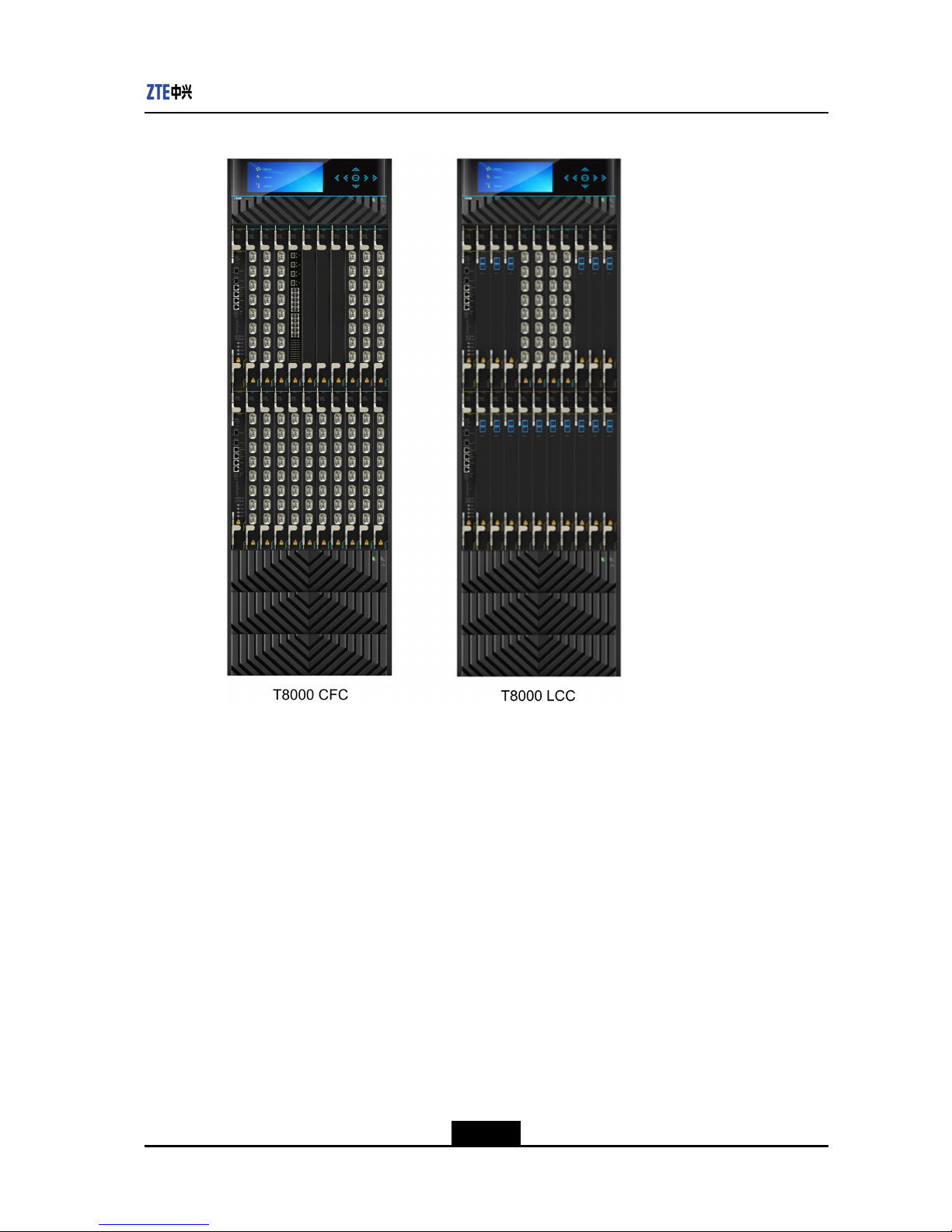
CentralSwitchingShelfandLineCardShelf
Inaclustersystem,ZXR10T8000devicescanbedividedintocentralswitchingshelves
andlinecardshelvesbyfunctionality.Theyholddifferenttypesofboards.
TheappearanceofacentralswitchingshelfandalinecardshelfisasshowninFigure1-1.
1-2
SJ-20110901170352-005|2011-10-15(R2.0)ZTEProprietaryandCondential
Chapter1IntroductiontoCluster
Figure1-1ZXR10T8000CentralSwitchingShelfandLineCardShelf
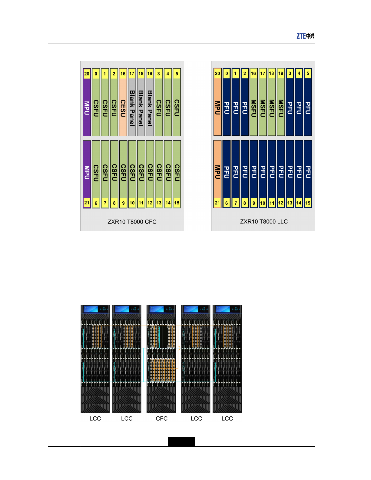
Theslotallocationwithinacentralswitchingshelfandalinecardshelfisasshownin
Figure1-2.
1-3
SJ-20110901170352-005|2011-10-15(R2.0)ZTEProprietaryandCondential
ZXR10T8000HardwareInstallationGuide(Cluster)
Figure1-2SlotAllocationWithinaCentralSwitchingShelfandLineCardShelf
Cluster1+4
ZXR10T8000Cluster1+4iscomposedofonecentralswitchingshelfandupto4linecard
shelves.
TheoverallcascadeconnectionsofZXR10T8000cluster1+4areasshowninFigure1-3.
Figure1-3OverallCascadeConnectionsofZXR10T8000Cluster1+4
1-4
SJ-20110901170352-005|2011-10-15(R2.0)ZTEProprietaryandCondential
Chapter1IntroductiontoCluster
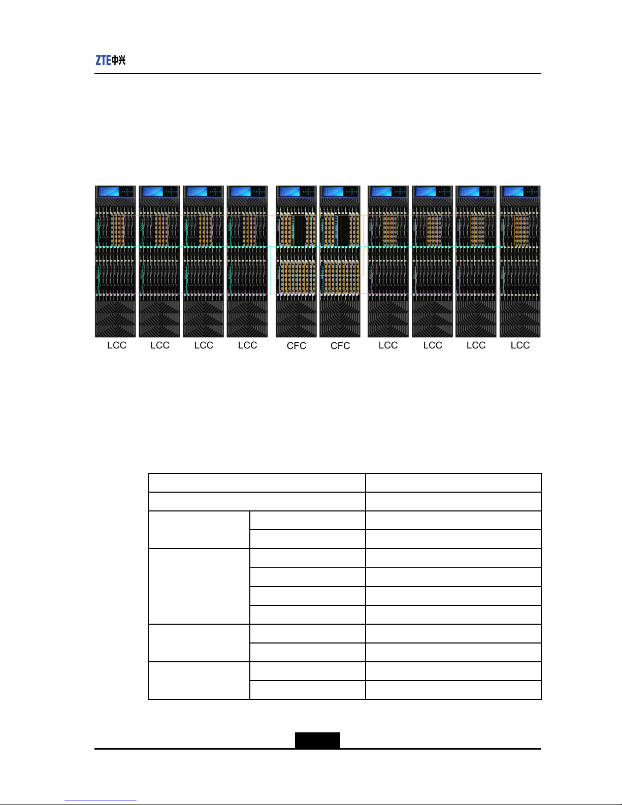
Cluster2+8
ZXR10T8000Cluster2+8iscomposedoftwocentralswitchingshelvesandupto8line
cardshelves.
TheoverallcascadeconnectionsofZXR10T8000cluster2+8areasshowninFigure1-4.
Figure1-4OverallCascadeConnectionsofZXR10T8000Cluster2+8
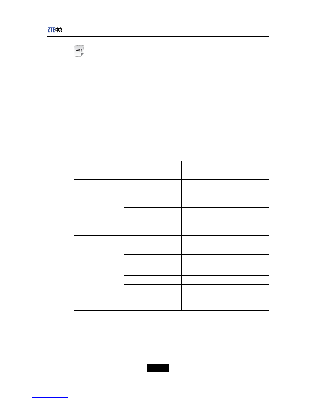
1.3PhysicalParametersofCluster
PhysicalParametersofaLineCardShelf
FortheparametersofalinecardshelfoftheZXR10T8000clustersystem,seeT able1-1.
Table1-1PhysicalParametersofaLineCardShelfoftheZXR10T8000ClusterSystem
PhysicalParameterZXR10T8000
Size(WidthxHeightxDepth)442mmx1686mmx740mm
Shelf(includingbackplane)64kg
Weight
Fullconguration240kg
Totalnumberofslots22
NumberofMPUslots2
NumberofSFUslots4
Numberofslots
NumberofPFUslots16
Perslot120Gbps
Switchingcapacity
Permachine1.92Tbps
Perslot40G
Portthroughput
Permachine640G
1-5
SJ-20110901170352-005|2011-10-15(R2.0)ZTEProprietaryandCondential

ZXR10T8000HardwareInstallationGuide(Cluster)
PhysicalParameterZXR10T8000
Perslot100Mpps
Packetforwarding
capacity
Permachine1600Mpps
Backupmode1+1
Ratedpowerpermachine6000W
Ratedvoltage-48V
Maximumvoltagerange-60V--40V
Ratedinputcurrent75A/channel(for2subareapowersupply)
DCpowersupply
Aircircuitbreaker100A(fullconguration,supporting2
subareapowersupply)
Backupmode4+4
Ratedpowerpermachine6000W
Ratedinputvoltage200V-240V
Inputfrequencyrange50Hz-60Hz
Ratedoutputvoltage-53.5V
RatedoutputcurrentNA
ACpowersupply
Ratedoutputpowerper
module
2000W/module
Numberofhorizontalfan
modules
2
Numberoffansinhorizontal
fanmodules
9
Backupmode1+1
VariableratecontrolmodeSupported
Coolingsystem
Heatdissipation14469BTU/hour
Temperature-5°C-50°C
Humidity5%-90%
Operational
environment
requirements
Altitude<5000m
Temperature-40°C-+70°C
Storageenvironment
requirements
Humidity0-95%
Groundingresistance
Thegroundingresistanceincaseofjoint
groundingislessthan5Ω.
1-6
SJ-20110901170352-005|2011-10-15(R2.0)ZTEProprietaryandCondential
Chapter1IntroductiontoCluster
Note:
Ifthealtitudeisbelow1800m,thelong-termoperatingtemperatureis40°Candthe
short-termoperatingtemperatureis50°C.
Ifthealtitudeisabove1800m,themaximumtemperatureoftheoperatingenvironment
decreasesby0.5°Cforevery100-meterincreaseinaltitude.Themaximumsupported
altitudeis5000m.
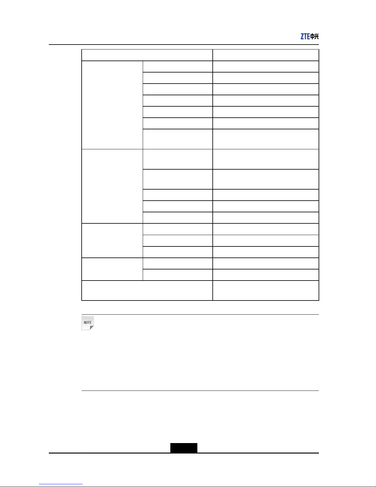
PhysicalParametersofaCentralSwitchingShelf
FortheparametersofacentralswitchingshelfoftheZXR10T8000clustersystem,see
Table1-2.
Table1-2PhysicalParametersofaCentralSwitchingShelfoftheZXR10T8000Cluster
System
PhysicalParameterZXR10T8000
Size(WidthxHeightxDepth)442mmx1686mmx740mm
Shelf(includingbackplane)64kg
Weight
Fullconguration240kg
Totalnumberofslots22
NumberofMPUslots2
NumberofCSFUslots16
Numberofslots
NumberofCESUslots4
SwitchingcapacityPermachine7.68Tbps
Backupmode1+1
Ratedpowerpermachine5100W
Ratedvoltage-48V
Maximumvoltagerange-60V--40V
Ratedinputcurrent75A/channel(for2subareapowersupply)
DCpowersupply
Aircircuitbreaker100A(fullconguration,supporting2
subareapowersupply)
1-7
SJ-20110901170352-005|2011-10-15(R2.0)ZTEProprietaryandCondential
ZXR10T8000HardwareInstallationGuide(Cluster)
PhysicalParameterZXR10T8000
Backupmode4+4
Ratedpowerpermachine5100W
Ratedinputvoltage200V-240V
Inputfrequencyrange50Hz-60Hz
Ratedoutputvoltage-53.5V
RatedoutputcurrentNA
ACpowersupply
Ratedoutputpowerper
module
2000W/module
Numberofhorizontalfan
modules
2
Numberoffansinhorizontal
fanmodules
9
Backupmode1+1
VariableratecontrolmodeSupported
Coolingsystem
Heatdissipation13923BTU/hour
Temperature-5℃-50℃
Humidity5%-90%
Operational
environment
requirements
Altitude<5000m
Temperature-40°C-+70°C
Storageenvironment
requirements
Humidity0-95%
Groundingresistance
Thegroundingresistanceincaseofjoint
groundingislessthan5Ω.
Note:
Ifthealtitudeisbelow1800m,thelong-termoperatingtemperatureis40°Candthe
short-termoperatingtemperatureis50°C.
Ifthealtitudeisabove1800m,themaximumtemperatureoftheoperatingenvironment
decreasesby0.5℃forevery100-meterincreaseinaltitude.Themaximumsupported
altitudeis5000m.
1.4ClusterInstallationFlow
ThistopicdescribeshowtoinstallZXR10T8000cluster1+4andcluster2+8.The
installationowofthetwoclustersisbasicallythesame,asshowninFigure1-5.
1-8
SJ-20110901170352-005|2011-10-15(R2.0)ZTEProprietaryandCondential

Chapter1IntroductiontoCluster
Figure1-5ZXR10T8000ClusterInstallationFlow
1-9
SJ-20110901170352-005|2011-10-15(R2.0)ZTEProprietaryandCondential

ZXR10T8000HardwareInstallationGuide(Cluster)
Thispageintentionallyleftblank.
1-10
SJ-20110901170352-005|2011-10-15(R2.0)ZTEProprietaryandCondential

Chapter2
InstallationofClusterin1+4
Mode
TableofContents
InstallationPreparations.............................................................................................2-1
InstallationofCascadeConnectionCables.................................................................2-1
2.1InstallationPreparations
BeforeinstallingZXR10T8000cluster1+4,checktheinstallationenvironmentand
preparerelatedtechnicaldocumentation,tools,andqualiedinstallationpersonnel.For
details,refertosection"InstallationPreparations"intheZXR10T8000Carrier-Class
RouterInstallationManual(SingleMachine).
Beforeclusterconnection,ensurethateachZXR10T8000singlemachineisinstalled
completely,includingthecabinet,componentswithinthecabinet,protectiveearthwires
andpowercords.Fordetailedinstallationprocedureandcaveats,refertotheZXR10
T8000Carrier-ClassRouterInstallationManual(SingleMachine).
Inaddition,ensurethatsufcientclusterdedicatedbersarereadyandrelatedcluster
boardsareinstalled.
2.2InstallationofCascadeConnectionCables
2.2.1InstallingCascadeDataCables
DataCableCascadingMethod
ThecascadedatacablesintheZXR10T8000clustersystemareopticalcables.Itis
requiredthatthecascadeinterfacesofeachcascadeswitchingnetworkboard(MSPU)
onalinecardshelf(LCC)beconnectedtothecascadeinterfacesofacentralswitching
networkboard(CSFU)onthecentralswitchingshelf,soastoformathree-levelCLOS
switchingarchitecture.Thus,networkprocessingboards(PFUs)ondifferentlinecard
shelvescanswitchdatasmoothly.
EachMSFUonanLCCprovides8cascadeinterfaces.OneLCCprovidesupto4MSFUs.
Thatis,oneLCCprovidesupto32cascadeinterfaces.EachCSFUonaCFCprovides8
cascadeinterfaces.OneCFCprovidesupto16CSFUs.Thatis,oneCFCprovidesupto
128cascadeinterfaces.
2-1
SJ-20110901170352-005|2011-10-15(R2.0)ZTEProprietaryandCondential
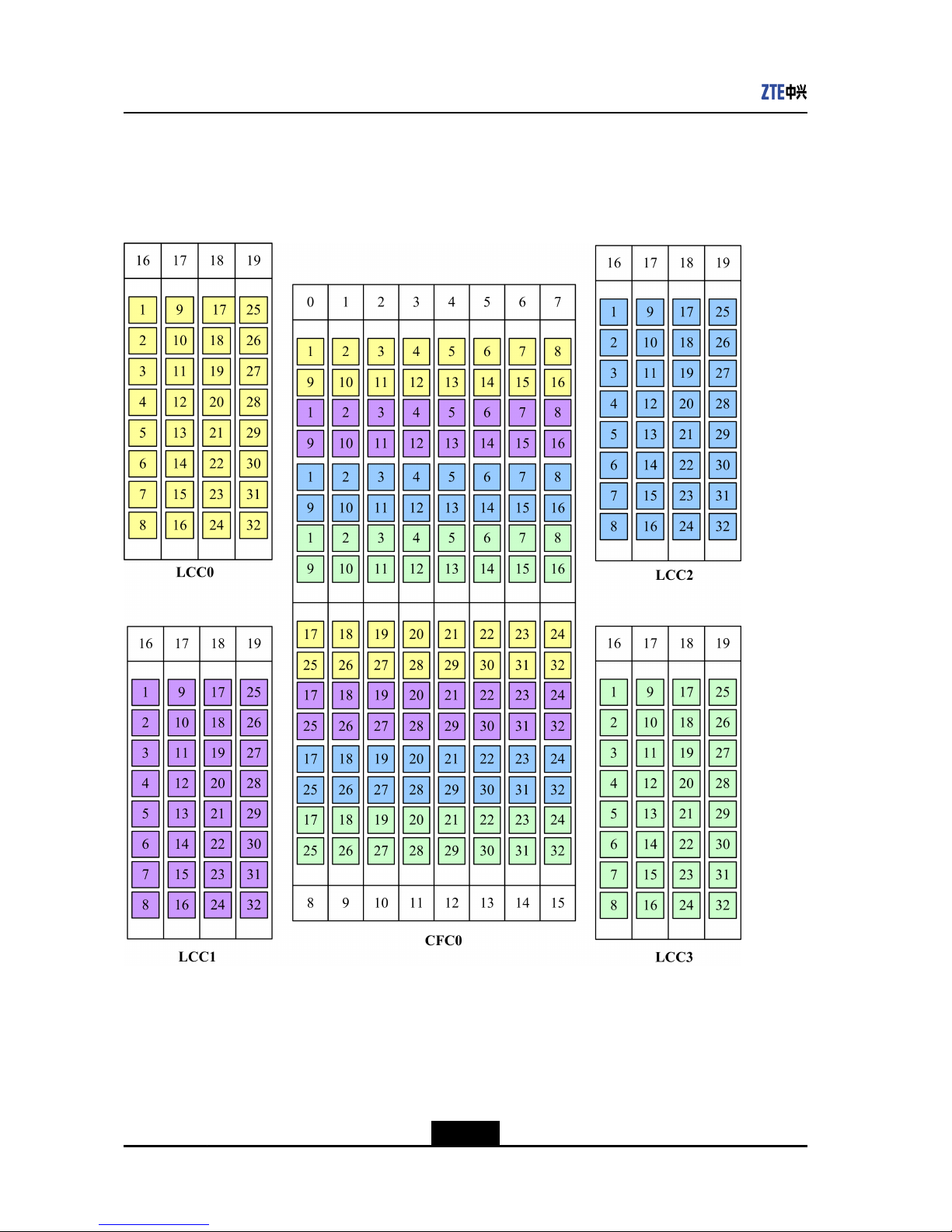
ZXR10T8000HardwareInstallationGuide(Cluster)
ThedataplanecascadeconnectionsoftheZXR10T8000cluster1+4systemareasshown
inFigure2-1.TheinterfacesonanLCCareconnectedtotheinterfacesofthesamecolor
andnumberontheCFC.
Figure2-1ZXR10T8000DataPlaneCascadeConnectionsofCluster1+4
InstallingCascadeFibers
Beforeinstallingcascadebers,reserveacablingpathandspace,andpreparesufcient
cascadebers.
Toinstallclusterdedicatedbers,followthesesteps:
2-2
SJ-20110901170352-005|2011-10-15(R2.0)ZTEProprietaryandCondential
Chapter2InstallationofClusterin1+4Mode
1.Inserttheberconnectorintoaninterfaceoftherelatedboard.
2.Tightenthescrewontheberconnectorclockwise.
3.Sticklabelsonbothsidesofthebertodescribetheinformationabouttheber.
4.Usecablestrapstoorganizeandbindthebersincompliancewithrelated
specications.
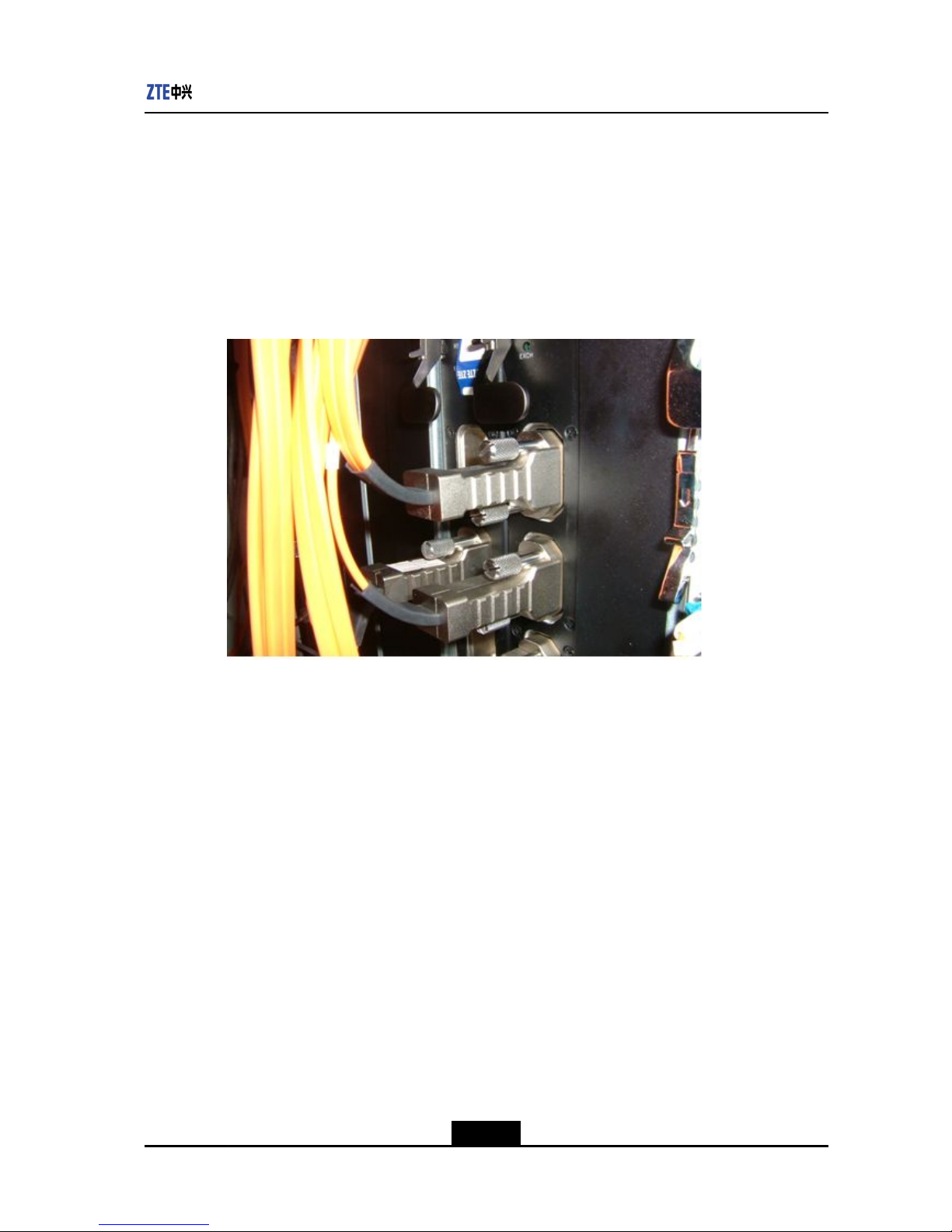
ThedataplanecascadebersoftheZXR10T8000clustersystemareasshowninFigure
2-2.
Figure2-2DataPlaneCascadeFibers
Figure2-3showssomerowsofbersconnectedintheclusterinstallation.
2-3
SJ-20110901170352-005|2011-10-15(R2.0)ZTEProprietaryandCondential
 Loading...