

Zte ZXR10 5900, ZXR10 5200 Product Description

ZXR10 5900 5200 Product
Description

ZXR10 5900 5200 Product Description
ZTE
Confidential Proprietary
© 2010
ZTE Corporation. All rights reserved.
I
ZXR10 5900 5200 Product Description
Version Date Author Approved By Remarks
V1.00 2008-5-30 Mao yucheng Ma gang Not open to the Third Party
V2.00 2009-9-16 Mao yucheng Ma gang
Updating format
© 2010 ZTE Corporation. All rights reserved.
ZTE CONFIDENTIAL: This document contains proprietary information of ZTE and is not to be
disclosed or used without the prior written permission of ZTE.
Due to update and improvement of ZTE products and technologies, information in this document
is subjected to change without notice.

ZXR10 5900 5200 Product Description
II © 2010 ZTE Corporation. All rights reserved.
ZTE Confidential
Proprietary
TABLE OF CONTENTS
1 Overview .................................................................................................................1
2 Highlights................................................................................................................5
2.1 Fully Support IPv6 ....................................................................................................5
2.2 SVLAN .....................................................................................................................5
2.3 Innovative VCT Technology .....................................................................................8
2.4 VBS Realizes Precise User Location ........................................................................8
2.5 Redundant Power Supply System ............................................................................9
2.6 ZESR Ring Protection ..............................................................................................9
2.7 Stacking Function .................................................................................................. 10
2.8 Supporting IPTV..................................................................................................... 11
2.9 Powerful Security Feature ...................................................................................... 11
3 Functionality ......................................................................................................... 13
3.1 MAC Address Management ................................................................................... 13
3.2 Basic VLAN............................................................................................................ 13
3.3 QinQ ...................................................................................................................... 14
3.4 PVLAN ................................................................................................................... 14
3.5 VLAN Translation ................................................................................................... 15
3.6 Super VLAN ........................................................................................................... 15
3.7 Spanning Tree Protocol (STP)................................................................................ 15
3.8 Link Aggregation .................................................................................................... 16
3.9 Port Mirroring ......................................................................................................... 16
3.10 IGMP Snooping...................................................................................................... 17
3.11 802.1x .................................................................................................................... 17
3.12 VRRP Protocol ....................................................................................................... 18
3.13 IPv4 Unicast Routing Protocol ................................................................................ 18
3.13.1 RIP Protocol........................................................................................................... 18
3.13.2 OSPF Protocol ....................................................................................................... 19
3.13.3 IS-IS Protocol ......................................................................................................... 20
3.13.4 BGP Protocol ......................................................................................................... 20
3.14 IPv4 Multicast Routing Protocol .............................................................................. 21
3.14.1 IGMP protocol ........................................................................................................ 21
3.14.2 PIM-SM.................................................................................................................. 21
3.14.3 PIM-Snooping ........................................................................................................ 23
3.15 DHCP .................................................................................................................... 23
3.16 Super extendable stacking ..................................................................................... 23
3.17 IPv6 ....................................................................................................................... 23
3.17.1 IPv6 Routing Protocol .......................................................................................... 24
3.17.2 IPv6 Multicast Routing Protocol .............................................................................. 24
3.17.3 The Transition Technology for IPv6 Deployment..................................................... 24
3.18 ACL Technology of 59/52 Switches ........................................................................ 24
3.18.1 Standard ACL ........................................................................................................ 25
3.18.2 Expanded ACL Technology .................................................................................... 25
3.18.3 L2 ACL .................................................................................................................. 26
3.18.4 Hybrid ACL technology........................................................................................... 27
3.19 QoS Technology .................................................................................................... 28
3.19.1 Brief Introduction to QoS ........................................................................................ 28
3.19.2 QoS Technology for ZXR10 59/52 switch series ..................................................... 32
3.19.3 QoS Applications ................................................................................................... 40
4 System Architecture ............................................................................................. 42
4.1 Product Physical Structure ..................................................................................... 42

ZXR10 5900 5200 Product Description
ZTE
Confidential Proprietary
© 2010
ZTE Corporation. All rights reserved.
III
4.2 Hardware Architecture............................................................................................ 44
4.2.1 Switching and Control Module ................................................................................ 45
4.2.2 Power Supply Module ............................................................................................ 46
4.2.3 Interface Modules .................................................................................................. 46
4.3 Software Architecture ............................................................................................. 48
4.3.1 Overview................................................................................................................ 48
4.3.2 Description of Various Layers ................................................................................. 52
4.3.3 Functional Modules Description .............................................................................. 53
5 Technical Specifications ...................................................................................... 63
5.1 Physical Specifications ........................................................................................... 63
5.2 Capacity................................................................................................................. 63
5.3 Performance .......................................................................................................... 63
5.4 Power Supply Specification .................................................................................... 65
5.5 Working Environment ............................................................................................. 65
5.6 Reliability ............................................................................................................... 66
6 Typical Networking ............................................................................................... 67
7 The Type and Specification of Cable and Fiber .................................................. 68
7.1 Model and Specification of Cable ........................................................................... 68
7.2 Model and Specification of Fiber ............................................................................ 68
8 Acronyms and Abbreviations .............................................................................. 69

ZXR10 5900 5200 Product Description
IV © 2010 ZTE Corporation. All rights reserved.
ZTE Confidential
Proprietary
FIGURES
Figure 1 User VLAN Tag Message ...........................................................................................7
Figure 2 User Band VLAN Tag Message ..................................................................................7
Figure 3 Stack Example ......................................................................................................... 10
Figure 4 FIFO Scheduling ...................................................................................................... 33
Figure 5 SP Scheduling ......................................................................................................... 34
Figure 6 WRR scheduling ...................................................................................................... 34
Figure 7 WRR scheduling ...................................................................................................... 35
Figure 8 WFQ scheduling ...................................................................................................... 35
Figure 9 Relationships between WRED and Queue Mechanism ............................................. 37
Figure 10 Basic Processing of Traffic Control in CIR ................................................................ 38
Figure 11 TS processing .......................................................................................................... 39
Figure 12 QoS Processing of the ZXR10 59/52 Switches Series .............................................. 40
Figure 13 VOIP Support ........................................................................................................... 41
Figure 14 The front panel of ZXR10 5952/5252 ........................................................................ 42
Figure 15 The front panel of ZXR10 5928/5928-PS/5228 ......................................................... 42
Figure 16 The front panel of ZXR10 5928-FI/5228-FI ............................................................... 42
Figure 17 The front panel of ZXR10 5224 ................................................................................ 42
Figure 18 Functional Block Diagram for the hardware system of ZXR10 59/52 series ............... 44
Figure 19 Functional Block Diagram of Main Control Board ...................................................... 45
Figure 20 The AC power supply of ZXR10 59/52 series switch ................................................. 46
Figure 21 The DC power supply of ZXR10 59/52 series switch................................................. 46
Figure 22 The Functional Block Diagram for 1-port 10GE interface board................................. 47
Figure 23 The panel of 1-port 10GE optical interface board ...................................................... 47
Figure 24 The panel of 1-port 10GE electrical interface board .................................................. 48
Figure 25 The Functional Block Diagram for the Operation Support Subsystem ....................... 50
Figure 26 Functional Block Diagram of L2 Subsystem .............................................................. 51
Figure 27 Functional Block Diagram of L3 Subsystem .............................................................. 52
Figure 28 Software functional modules of ZXR10 59/52 series ................................................. 53
Figure 29 Functional Block Diagram of the Unicast Routing Protocol Subsystem...................... 59
Figure 30 Implementation in MAN ............................................................................................ 67
TABLES
Table 1 Basic features of ZXR10 59/52 intelligent secure Ethernet Switch ..............................2
Table 2 Attributes Ethernet electric interface on the front panel of ZXR10
5952/5252/5928/5928-PS/5228 ................................................................................ 43
Table 3 Indicators on the panel of ZXR59/52 series switch .................................................... 43
Table 4 Attributes of gigabit Ethernet optical interface ........................................................... 44
Table 5 The attributes of 10GE interface board ..................................................................... 48
Table 6 The functions of the indicators on the panel of 1-port 10GE interface board .............. 48
Table 7 Models and Specifications of Cable .......................................................................... 68
Table 8 Specifications of 1000BASE-SX Fiber ...................................................................... 68
Table 9 Acronyms and Abbreviations .................................................................................... 69

ZTE Confidential
Proprietary
© 2010ZTE Corporation. All rights reserved.
1
1 Overview
With the exponential growth of Internet traffic, IP has globally become the first choice of
networking technology for building the new generation network infrastructure, and IPbased services are now becoming more important from networks of service providers.
Communication networks are experiencing intense evolution. To accommodate this
evolution, network carriers are taking new initiatives to build broadband IP networks that
simultaneously carry data, voice and video services.
As Ethernet switches provide broad range of services and deliver much higher
performance, they have been finding applications on increasingly more IP networks.
ZXR10 59/52 series L3 Gigabit Intelligent Switch launched by ZTE CORPORATION is
mean to fully satisfy IP routing/switching and high QoS assurance needs. This series
support complete IPv4 and IPv6 routing protocols, VLAN control, Ethernet switching,
QoS assurance mechanisms, traffic control, 802.1x, and anti-virus protection, as well as
complete service control and user management capability. These intelligent
characteristics make them all suitable to be used as L3 switches on service provider
networks, enterprise networks and campus networks that focus on service management
control and network security assurance capability.
ZXR10 5900 5200 Product Description
Specifically designed for the access and aggregation layers of broadband IP MANs and
enterprise networks, ZTE ZXR10 59/52 series mid-range/high-end all-gigabit-port
intelligent Ethernet switches provide low to medium density of Ethernet ports, making
them most suitable to be used as user-side access device for intelligent broadband
residential areas, office buildings, hotels, college campuses and enterprise networks
(government networks), or as aggregation device for medium-size networks providing
users with high-speed, efficient and high price-performance-ratio aggregation solution.
Depending on actual network requirement, they offer different combinations of optical
and electrical interfaces for aggregation, for which they are ideal network
aggregation/access devices for large enterprises, high-grade residential areas, hotel,
and college campus networks.
The features of ZXR10 59 series intelligent secure Ethernet switch are:
Carrier-Class Reliability
Providing redundancy on the physical layer, supporting power redundancy and hotswappable modules; providing redundancy on the protocol layer, and supporting the
protocols such as LACP, VRRP and route load sharing.
Wire-Speed Forwarding and Filtering
ASIC hardware switching is used to ensure the wire-speed forwarding of L2, L3 and
IPv6 packets. ASIC hardware filtering is used to ensure packets filtering on L2-L7 and
wire-speed performance of L2-L4 ACL.
Various Protocols Support
Supporting complete and advanced network protocols such as L2, L3, unicast routing,
multicast routing, IPv4, IPv6 and access authentication, keeping up with current
development of the network, and meeting the needs of the users for building advanced
Ethernet networks.
ZXR10 5900 5200 Product Description
2 © 2010 ZTE Corporation. All rights reserved.
ZTE Confidential
Proprietary
Open System Architecture, Superior Upgrade Capability
With superior upgrade capability, open system architecture is used to protect
subscribers’’ investment and meet customers’ future requirements for new features.
The features of ZXR10 52 series intelligent secure Ethernet switch are:
Carrier-Class Reliability
It provides redundancy on the physical layer, supports power redundancy and hotswappable modules, provides redundancy on the protocol layer and supports the
protocols such as LACP and routing load sharing.
Wire-Speed Forwarding and Filtering
ASIC hardware switching is used to ensure the wire-speed forwarding of L2, L3 packets.
ASIC hardware filtering is used to ensure packets filtering on L2-L7 and wire-speed
performance of L2-L4 ACL.
Rich Network Protocol Supports
Supporting most advanced network protocols such as L2, L3, unicast routing, multicast
routing, IPv4, and access authentication, keeping up with current development of the
network, and meeting the needs of the users for building advanced Ethernet networks.
Open System Architecture, Superior Upgrade Capability
With superior upgrade capability, open system architecture is used to protect
subscribers’’ investment and meet customers’ future requirements for new features.
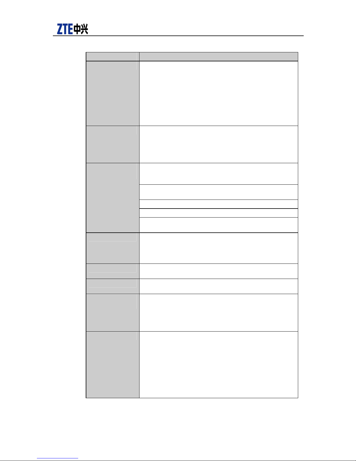
Table 1 Basic features of ZXR10 59/52 intelligent secure Ethernet Switch
Item Description
Basic features
Switching capacity: 5952/5252: 320G 5928/5928PS/5228/5928-FI/5228-FI/5224: 240G
Packet forwarding rate(PPS): 5952/5252: 131M
5928/5928-PS/5228/5928-FI/5228-FI: 95.2M
5224: 35.7M
Number of entries in the routing table: for 59-series, 16K (L3)
for 52-series, 4K (L3)
MAC address table size:
5952/5252/5928/5928-PS/5928-FI/5228/5228-FI: 16K
5224: 8K
Number of slots ZXR10 5952/5252/5928/5928-PS/5228/5928-FI/5228-FI: 4
slots
ZXR10 5900 5200 Product Description
ZTE Confidential
Proprietary
© 2010ZTE Corporation. All rights reserved.
3
Item Description
L2 protocol support Support IEEE 802.3, IEEE 802.3u, IEEE 802.3z, IEEE
802.3ae, IEEE 802.3x, and IEEE 802.1p, etc.
Support IEEE 802.1d STP, IEEE802.1w RSTP, IEEE802.1s
MSTP protocols
Support IEEE 802.3ad LACP link aggregation
Support IEEE802.1Q , VLAN number: 4094
Support VLAN based upon port, protocol and subnet, and
support PVLAN
Support dual VLAN labels (SVLAN or QinQ)
L3 protocol support 59-series support RIP1/2, OSPF, BGP, IS-IS, VRRP routing
protocols.
52-series support RIP1/2 routing protocol
Support Super VLAN
59-series support IPv6
Service functions
QoS attributes Support eight priority queues
Stacking Support super expansion stacking (SES) with maximum
Interface module 1-port 10XGE interface(optical/XFP) 1-port 10XGE
Device
management
Power supply Power supply (AC): 100V~240V, 50Hz ~60Hz
Multicast: 59 series supports multicast routing protocols such
as IGMP, PIM-DM/SM, MSDP and MBGP, etc. 52 series
supports IGMP multicast routing protocol.
Bandwidth control: Port-, application- and flow-based
bandwidth control with the granularity of 64kbps
Authentication function: Support 802.1x and RADIUS Client
DHCP: Support DHCP Relay and DHCP Server
5928-PS supports POE,IEEE 802.3af, power <30W every port.
Max support port number 24. The whole support power 820W
L2-based priority queuing
Flow control based on L2, L 3, L4 source and destination
L4-based application flow control
support of 32
interface(electrical/CX4)
Support SNMP MIB, MIB II (RFC 1213)
Support RMONV1/V2/V3
Support port mirroring: Includes control module, feature port
and special slot
Support Console/Telnet/SSHmanagement
Power supply (DC): -57V~-40V
5952/5252 Power consumption with full configuration < 150W
5928/5228 Power consumption with full configuration <100 W
5928-PS Power consumption with full configuration <820 W
5928-FI/5228-FI Power consumption with full configuration <
100W
5224 Power consumption with full configuration 80W
ZXR10 5900 5200 Product Description
4 © 2010 ZTE Corporation. All rights reserved.
ZTE Confidential
Proprietary
Item Description
Reliability MTBF: >100000 hours
Physical
parameters
Environmental
Requirements
MTTR: <30 minutes
All the modules are hot-swappable, support external 12V
power supply redundancy.
Dimensions:
5952/5252 43.6(H)*442(W)*400(D)
5928/5928-PS/5228 43.6(H)*442(W)*360(D)
5928-FI/5228-FI 43.6(H)*442(W)*320(D)
5224 43.6(H)*442(W)*280(D)
Weight: 5952/5252 <12kg
5928/5228/5928-FI/5228-FI <8kg
5928-PS<9kg
5224 <6kg
Operating temperature: -5°C~+45°C
Storage temperature: -40°C~+70°C
Operating relative humidity: 5%~95%, non-condensing

ZTE Confidential
Proprietary
© 2010ZTE Corporation. All rights reserved.
5
2 Highlights
2.1 Fully Support IPv6
Due to the rapid development of data network, NGN and 3G network, there are more
and more demands for IPv6 in the market. The worldwide research centers, carriers and
business customers are busy with the test and deployment of IPv6 network.
ZTE is an active participant in making national IPv6 standard. In 2002, ZTE achieved
“High-Performance IPv6 Forwarding Platform” project belonging to State 863 Project
Packet. From April 2nd to April 4th 2003, ZTE joined in “Global IPv6 Peek Forum 2003”
and showed its new IPv4/v6 dual-stack router and IPv6 network solution. In May 2004,
ZTE high-end router successfully passed MII (Ministry of Information Industry) IPv6
network access test. In September 2004, ZTE the first Chinese vendor got International
IPv6 Ready certificate. All the facts show that currently ZTE NGN IPv6 technology has
been in line with most International vendors.
Currently, the IPv6 protocols supported by ZTE ZXR10 59/52 series Ethernet switch
ZXR10 5900 5200 Product Description
Support IPv6 basic protocols including IPv6 protocol and ND (Neighbor Discovery)
protocol.
Support TCP6, UDP6 and Socket IPv6.
Support Telnet6, gives convenient to remote user to log in via telnet6.
Support PMTU(Path MTU Discovery) function
Provide multiple IPv6 link detection method
Provide IPv6 policy route
There’s still a long way for us to develop IPv4 technology to IPv6 technology. ZTE
ZXR10 59/52 series Ethernet switch provides rich solutions to transfer IPv4 network to
IPv6 network. The following IPv4/IPv6 transition technologies are involved:
Supports IPv4/IPv6 dual stacking
Supports IPv6 tunnel: manual configured tunnel, auto configured tunnel, 6to4
tunnel
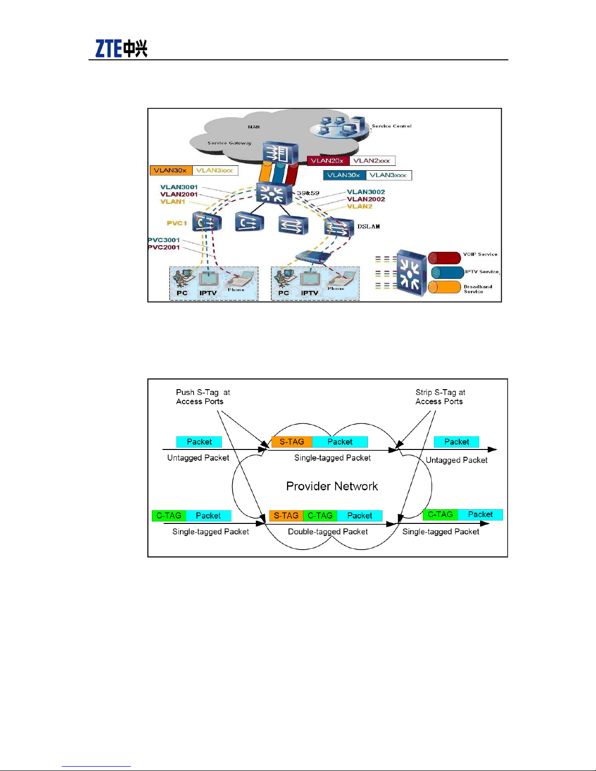
2.2 SVLAN
SVLAN also named flexible QinQ is the development and enhancement of QinQ.
Compared with old QinQ which is not very flexible as it can only be implemented by
increasing outer label on the port, SVLAN based upon port and C-Tag can tag different
S-Tags as per different situations. In addition, it can keep COS of customer message

ZXR10 5900 5200 Product Description
6 © 2010 ZTE Corporation. All rights reserved.
ZTE Confidential
Proprietary
and copy 802.1p field of inner label to the outer label to keep the continuity of customer
QoS.
SVLAN has enhanced function of network user location, which enables QinQ to better
support PUPV (one VLAN per user) and PSPV (one VLAN per service). It is easy for
carrier’s operation and maintenance management. The most typical application is Triple
Play service in broadband to the home.
SVLAN can perfectly solve the problem of user location separation and service
differentiation in broadband network. It can implement operation and maintenance
management for one VLAN per user, which brings great convenience to network
management and maintenance. ZTE is always an advocator of this technology and
takes the leading position in the industry.
ZXR10 59/52 series switch supports SVLAN with the following applications and
functions:
Being able to distinguish different service VLAN at one port and tag different outer
layer label based on different service requirements.
Being able to implement coexistence of VLAN transparent transmission and QinQ
service at port. Being able to keep user label unchanged without adding new label
to user label when some VLAN packets are going through switch.
Being able to duplicate 801.1p field in user label to outer layer label to guarantee
that user’s service level is kept unchanged in QinQ network so as to keep the
consistency of QoS of user service.
In IEEE802.1ad, S-Tag is for 0x88A8-type Ethernet, and C-Tag is for 0x8100-type
Ethernet. ZTE switch supports any C-Tag and S-Tag Ethernet.
SVALN has two major applications in the network:
SVLAN is applied in user location separation and service differentiation in network and
Triple Play service in family broadband. SVALN QinQ can solve traditional 4096 VLAN
resource shortage problem so as to truly implement PUPV and PSPV.
ZXR10 5900 5200 Product Description
ZTE Confidential
Proprietary
© 2010ZTE Corporation. All rights reserved.
7
Figure 1 User VLAN Tag Message
Figure 2 shows the adoption in L2 VPN of small network, or QinQ-based Tunnel or
QinQ-based VPN.
Figure 2 User Band VLAN Tag Message
In Figure 2, when customer messages with or without inner VLAN labels reach Ingress
PE (Provider Edge) switch, they may be tagged with corresponding outer labels
according to different switch ports, and then the messages will be transferred
transparently as per S-Tag in Provider Network. Later, theses customer messages will
de-capsulate their S-Tag on Egress PE equipment and then be sent to the related CE
equipment. The advantage of using QinQ VPN is that the Tag resources in Customer
Network and Provider Network are independent from each other. So customers can
make their own VLAN resource without concerning about the VLAN conflict in passing
Provider Network.

ZXR10 5900 5200 Product Description
8 © 2010 ZTE Corporation. All rights reserved.
ZTE Confidential
Proprietary
2.3 Innovative VCT Technology
VCT (Virtual Connection Test) designed based upon hardware detects the connection
fault. It realizes link diagnosis via TDR (Time Domain Reflection), and gives judgment on
the link faults for example open circuit, short circuit, impendence unmatched and normal
circuit. Besides, it can calculate the distance of the f ailed point of the link.
By using VCT technology, ZTE ZXR10 59/52 series Ethernet switches can carry out
remote maintenance to links to find out the open circuit, break circuit and the error for
detecting fault location is within 1 meter. Via VCT circuit, ZXR10 59/52 series Ethernet
switches can actively eliminate the incorrect customer configuration, and find out the
distance between the failed link and the equipment and port. It can locate and eliminate
most failures in network management center, which simplifies network maintenance and
reduces the costs and difficulties in network operation and maintenance.
2.4 VBS Realizes Precise User Location
VBAS (Virtual Broadband Access Server) is a query protocol used between IP-DSLAM
and BRAS.
It uses L2 end-to-end communication between BRAS and IP-DSLAM, i.e. the port
information query and responding message are directly encapsulated in L2 Ethernet
data frame, configure related DSLAM of VLAN on BAS and generates VBAS protocol in
the course of PPPoE session, that is, according to user’s VLAN, map to the
corresponding DSLAM, and BAS imitates user route label query to DSLAM actively, then
DSLAM gives BAS the route label of the responding customer. Here 59/52 series
switches are working as DSLAM device.
The implementation procedure of VBAS interaction:
User host initiates broadcasting session to generate data packet to ask for setting
up link, and wait for BAS responding.
After one or more than one BAS devices receive broadcasting, the data packets
providing by service are sent to user host if services can be provided.
Customer host selects one BAS as per a certain rule, and send unicast session to
require data packet.
When the selected BAS received the session for requiring data packet, it will
generate an exclusive Session ID, and then goes into PPP session stage after
sending data packet for confirmation to customer host.
When BAS sends data packet for confirmation, it will send VBAS request packet to
DSLAM for checking which physical port of DSLAM the MAC address of user host
comes from.
When DSLAM receives the request data packet from VBAS, it will send VBAS
responding data packet to BAS, and the relations between the MAC address and
DSLAM physical port will return.

ZXR10 5900 5200 Product Description
ZTE Confidential
Proprietary
© 2010ZTE Corporation. All rights reserved.
9
When the user host receives the confirming data packet from the selected BAS,
PPP session will be carried on according to Session ID and BAS. Via LCP, send
request packet for ID confirmation to BAS in a point-to-point way.
BAS sends authentication request packet to its background authentication system
(e.g., Radius Server). The authentication request consists of user account,
password and the info of its physical port.
The background authentication system (e.g. Radius Server) returns the responding
packet of BAS authentication.
BAS returns responding packet of user host authentication.
If the authentication is passed, then set up PPP link, so that both sides in the
communication can implement PPP data transmission.
The VBAS protocol of ZTE ZXR10 59/52 series Ethernet switches has the following
merits:
There’s no need of hardware upgrade. With few changes, only software upgrade on
the existing IP DSLAM and BRAS is required.
Only carry out port naming to IP DSLAM instead of making complicate configuration
on BRAS, which indicates little work.
There is no need of changing the existing networking mode, which protects the
existing investment and keeps sound continuity.
The binding between user and IP DSLAM physical port can be realized, that is, user
network suffering info can be got and user port status can be grabbed in advance.
2.5 Redundant Power Supply System
ZXR10 59/52 series switches support AC/DC power supply mode. Designed with -48V
DC power supply mode and 220V AC power supply mode, it can adopt an external 12V
redundant power supply module as well. With 1+1 hot backup power supply module, it
enhances the reliability of power supply system.
2.6 ZESR Ring Protection
ZESR (ZTE Ethernet Smart Ring) designed and developed based upon EAPS principle
of RFC 3619 protocol is used to test if the ring can get through to make sure any logical
path between any two points is smooth. According to the change of the ring (on->down,
down->on), reset the port status (block, forward), so that the logical path can get
switched over quickly.
ZESR is also adaptive to multi-ring and multi-domain environment. Multiple rings
referring to different layers in network topology where each layer is one ring, and there
ZXR10 5900 5200 Product Description
10 © 2010 ZTE Corporation. All rights reserved.
ZTE Confidential
Proprietary
are two access points in the low-layer ring connecting with high-layer access ring, so
that network topology is an independent ring and the tangent part of one ring actually
looks as part of the other ring. The ring with highest level is called main ring, the others
are called access ring. Multiple domains refer to multiple protection instances on one
ring adaptive to different service VLANs standing independently with different logical
paths.
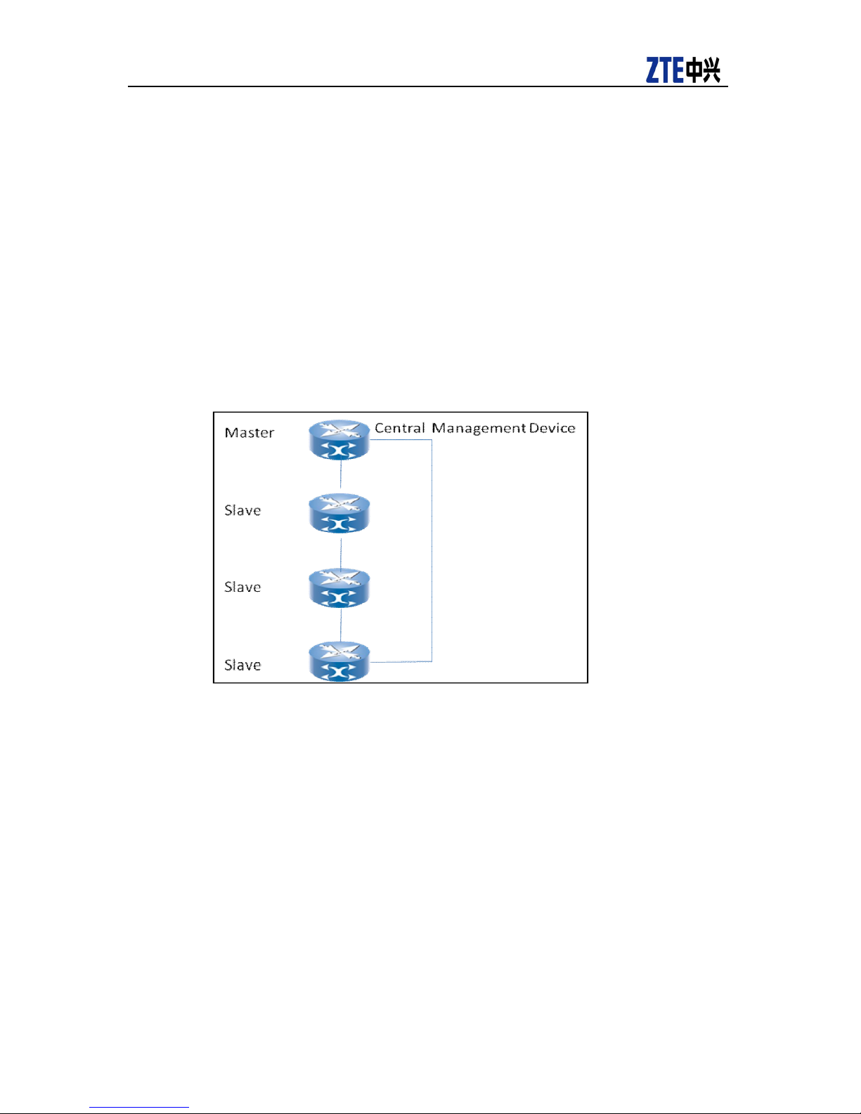
2.7 Stacking Function
ZXR10 52/59 supports SES stacking function. Stacking is a management domain
composing by some Ethernet switches connecting via stacking ports, where our main
switch and several standby switches exist. Normally daisy chain is used as shown in the
following figure:
Figure 3 Stack Example
Switches connect each other via stacking interfaces. Among devices, special protocol
message is used to control topology discovery, calculation, routing maintenance, etc.
The advantages stacking function brings to users are:
Sound Management: IRF stacking enables unified management of multiple devices.
One connection and one IP address can manage the entire Fabric, which obviously
reduces the costs.
Superior Extensibility: IRF stacking is capable of fitting different users’ demands and
guarantees smooth network extensibility, which maximally protects investment in
network upgrade.
N+1-mode backup features high reliability, which avoids single-point failure and
reduces service breakdown.

ZTE Confidential
Proprietary
© 2010ZTE Corporation. All rights reserved.
11
For single cassette switch, the system can implement the following characteristic
features:
Distributed management: in terms of management, all equipment belongs to one unit.
Administrator can control the devices via WEB, telnet, console, and SNMP. Different
devices are similar to different slots in a rack.
Distributed forwarding: instead of forwarding to the host, the message forwarding and
query can be done locally. With system redundancy, when one device breaks down,
other devices can implement normal forwarding as well.
Distributed link aggregation: support cross-device link aggregation, so that link backup
and load sharing can be implemented among devices.
2.8 Supporting IPTV
As a key technology of ZTE IPTV system, controllable multicast technology is mainly
used in broadband access network. The device (BRAS, DSLAM or Switch) realizing
multicast control policy is called multicast control point. The multicast control point
working as the ultimate point of user multicast IGMP query determine if multicast traffic
will be duplex to customer port as per related IGMP query and control policy. The closer
the multicast control point is from user, the less bandwidth the network requires. As an
important device implementing multicast control policy, the multicast control point must
support the following services: IGMP V1/V2, IGMP Snooping, IGMP Filter, IGMP Proxy,
IGMP Fast leave, MVR (Multicast VlLAN Register,), SGR(Static Group Register, static
multicast group register), UGAC(User Group Access Control, User Multicast Access
Control), and UGAR(User Group Access Record, User Multicast Access Record).
User’s authority for demanding services is controlled by binding rule and channel.
ZXR10 5900 5200 Product Description
2.9 Powerful Security Feature
ZXR10 52/59 switches provide customers with rich security features in control layer, data
layer and management layer of the devices respectively to implement overall protection.
The security mechanisms provided by these devices are:
Support MAC address table and ARP binding, MAC addresses filtering and
broadcasting suppression.
Support DHCP SNOOPING
Support CPU anti-attack (virus) protection, CPU overload/rhythm protection.
Support the feature of identifying multiple virus feature message, and filtering
LAND/BLAT/NULLScan/XmaScan/Smurf, SYN Flooding, Ping Flood, anti-DDoS
attack. Support Rood Guard of SPT, precaution against BPDU attack and ARP
attack.
Support uRPF unicast converse route inspection, precaution against pseudo
address attack.
Support OSPF/RIPv2/BGPv4 MD5 cipher text checking.

ZXR10 5900 5200 Product Description
12 © 2010 ZTE Corporation. All rights reserved.
ZTE Confidential
Proprietary
Support IP source Guard.
Support hierarchical user management, user encryption and SSH.

ZTE Confidential
Proprietary
© 2010ZTE Corporation. All rights reserved.
13
3 Functionality
3.1 MAC Address Management
For ZXR10 59/52 series, all forwarding tables and MAC addresses are closely related,
therefore MAC management module is the most fundamental as well as the most
important functional module in the Ethernet switch, since it performs basic functions
such as managing MAC addresses learning and performs the following management
operations:
MAC address binding: A specific MAC address can be bond with one port of the
switch. After that, no dynamic learning will be performed for the MAC address, so
that the physical location of a user can be restricted and important MAC addresses
can be protected
MAC address filtering: When the switch receives packets whose source or
destination MAC address are special MAC addresses, it can drop them to order to
filter some un-welcomed users
ZXR10 5900 5200 Product Description
Number of MAC addresses restriction: The number of MAC addresses of some
ports can be restricted to control the number of users of these ports. In addition,
prevention is made at the ports when they are under DOS attack to avoid
exhaustion of system resources
MAC address freeze: For a network that runs stably, the addresses of certain
important physical ports, such as uplink ports, can be freezed, in order to prevent
network interruptions due to the use of key MAC addresses by unauthorized users
MAC address display in multiple views: The VLAN table can be shown with
statistics collection in multiple aspects, such as VLAN, port, static or dynamic etc, to
help network diagnosis and maintain network stability.
3.2 Basic VLAN
VLAN is a fundamental protocol for L2 switching equipment, which enables administrator
to divide a physical LAN into multiple VLANs. Each VLAN has a VLAN ID to identify itself
uniquely within the entire LAN. Multiple VLANs share the switching equipment and links
of the physical LAN.
Logically, each VLAN is like an independent LAN, and all network frame traffics of a
VLAN are restricted within the VLAN. Inter-VLAN access can only be done via L3
forwarding, since direct access is not possible. In this way, network performance is
improved, and total traffic in the physical LAN can be effectively decreased.
The function of the VLAN is to reduce broadcast storm on the network, and to enhance
security and allows centralized management of the network.

ZXR10 5900 5200 Product Description
14 © 2010 ZTE Corporation. All rights reserved.
ZTE Confidential
Proprietary
59/52 switches series support 802.1Q VLAN. For untagged packets, VLAN tags can be
added to them based on subnet, protocol or port, so that a great variety of VLAN
features can be supported.
In the 802.1Q VLAN protocol, a VLAN is represented by a 12-bit number, so the number
of VLANs is limited within 4096, limiting some practical applications. The 59/52 switches
series provide four kinds of extensions. The first three are QinQ, PVLAN and VLAN
Translation, and the last one is Layer-3 related Super VLAN feature.
3.3 QinQ
QinQ, also known as multi-layer VLAN tag stacking, is a visualized name for the
tunneling protocol based on 802.1Q encapsulation. Its basic idea is to encapsulate
private VLAN tag into public VLAN tag, so that packets pass through the backbone
network with two tags, offering users with a simple L2 VPN tunneling technology. The
QinQ protocol is a simple while easy-to-be-managed protocol, since it does not require
the support of particular control protocol but can be implemented via static configuration
only. It is particularly useful for the switches on the aggregation layer. By supporting
QinQ (double tags), the switches on the aggregation layer can effectively increase the
number of VLANs in the MAN.
At present, IEEE is developing a specification for VLAN stacking, that is, 802.1adProvider Bridge. The external VLAN layer is defined as Service VLAN --- SVLAN, for
which the specification is still in draft.
In the software system of the 59/52, the QinQ software function module performs static
configuration of QinQ, and perform appropriate configuration for the chipsets. In QinQ,
there are two forms of VLANs:
SVLAN (Service VLAN): VLAN defined on the backbone network
CVLAN (Customers VLAN): User-defined VLAN
The QinQ software function module adds one parameter in the VLAN table, to order to
indicate whether the VLAN is a SVLAN or CVLAN, and the bottom-layer driver interface
function is used to set the QinQ function for the chipset.
3.4 PVLAN
For the scenario where all servers are located within a subnet but they can only
communicate with their default gateways, this new VLAN feature is called Private VLAN.
In the concept of Private VLAN, there are three types of ports of the switch: Isolated Port,
Community Port and Promiscuous Port. They correspond to different VLAN types
respectively: Isolated port belongs to Isolated PVLAN, Community port belongs to
Community PVLAN, while Promiscuous VLAN represents one complete Private VLAN.
Either of the first two types of VLANs must be bound within a Primary VLAN, which a
Promiscuous Port should also be included. For Isolated PVLAN, an Isolated Port can
only communicate with a Promiscuous Port, but it cannot exchange any traffic with
another Isolated Port. For Community PVLAN, a Community Port can communicate with
not only a Promiscuous port but also with another Community Port. The Promiscuous
Port is connected to an interface of another router or L3 switch. The traffic it receives
can then be forwarded to an isolated port or Community port.

ZTE Confidential
Proprietary
© 2010ZTE Corporation. All rights reserved.
15
Using PVLAN can be very effective for ensuring the security of data communication in
the network. A user only needs to connect its default gateway. One PVLAN can provide
connections with L2 data communication security without multiple VLAN and IP subnet.
All the users are connected to the PVLAN, so they are connected to the default gateway,
without access between any other users in the PVLAN. The PVLAN function ensures
that the ports within one VLAN cannot communicate between each other, while traffic
can only pass through via the Trunk port. In this way, even broadcast traffic from one
user in a VLAN will not affect another user within the same VLAN.
The PVLAN can be implemented on the ZXR10 59/52 simply through static configuration.
3.5 VLAN Translation
VLAN translation is also an expansion of the VLAN function. If one port of the switch has
the VLAN translation function enabled, the incoming data streams from that port must be
tagged. The VLAN translation function looks up in the MAC-VLAN table for a new VID by
using the combination of VID contained in the tag and the port number as the index, and
then the data streams will be switched using the new VLAN. This is the process of
translation from one VLAN to another.
The VLAN translation can be implemented on the ZXR10 59/52 simply through static
configuration. However, it should be noted that if the VLAN translation function is started,
the VLANs cannot be differentiated based on MAC addresses. On the contrary, if the
VLANs are needed to be differentiated based on MAC address, VLAN translation
function should be disabled.
ZXR10 5900 5200 Product Description
3.6 Super VLAN
Super VLAN allows that hosts within same physical switching equipment belong to
different virtual broadcast domains and resides within the same IPv4 subnet with the
same default gateway. In current large-scale LAN switching environment, this
mechanism has a number of advantages over the traditional IPv4 addressing
mechanism. Its most important advantage is that it preserves address space in the IPv4
system.
Super VLAN uses the concepts of super virtual network and virtual sub-network to
perform dual-classification on the VLAN. One or multiple virtual sub-networks belong to
one super virtual network, and they will use the default gateway IP address of the super
virtual network.
The Super VLAN function is a pure software function. This function is transparent to the
Ethernet ASIC chip, which still performs data exchange according to the VLAN setting
made by the software module. Super VLAN can be implemented on the ZXR10 59/52
simply through static configuration.
3.7 Spanning Tree Protocol (STP)
STP is used to detect and eliminate loops between L2 switching functional units, and
provide redundancy links, for enhanced performance and reliability of the LAN.
This module performs the following two major functions:

ZXR10 5900 5200 Product Description
16 © 2010 ZTE Corporation. All rights reserved.
ZTE Confidential
Proprietary
Avoids network loop, prevents LAN broadcast storm due to such loop, and provides
redundant paths for backup.
Detect changes to the topology structure, and configure the spanning tree topology
again according to the change detected.
After the switch in a subnet executes STP, it will create a dynamic spanning tree
topology structure, where there will be no loop between any workstations in the LAN,
thus preventing broadcast storm. At the same time, STP also detects changes on the
topology, and creates a new spanning tree when the topology changes, providing fault
tolerance and allowing the re-configuration of the topology of the spanning tree.
According to the status information of the dynamic topology of the spanning tree, the
switch maintains and updates the MAC table, and finally implements f orwarding on the
MAC layer.
STP is designed to allow the switch to dynamically detect a loop-free (tree) of the
topology and ensure adequate connectivity, so that there is always a path between two
LANs as long as physically possible. According to the principles of graph theory, any
route graph containing nodes and connection nodes has a spanning tree of the routes
that ensure the connectivity to the destination but have no loop. Therefore, the spanning
tree algorithm and protocol can avoid loops in any dynamic topology, and can eliminate
those loops between any two workstations.
The Multiple Spanning Tree Protocol (MSTP) defined by IEEE802.1s is compatible with
the RSTP defined by IEEE802.1w and the common STP defined by IEEE802.1D.
Therefore, the spanning tree module only needs to implement the MSTP. When MSTP is
enabled, it can be forcedly set to RSTP or STP, so mixed networking applications of STP
and RSTP are supported. In addition, enabling SPT on the aggregated links and support
of STP based on ports is also supported.
ZXR10 59/52 series support STP, RSTP, and MSTP, as well as the mixed network
applications described above.
3.8 Link Aggregation
Link aggregation is the process where multiple physical links with the same media type
and same transmission rate are bundled together, and appear as one link logically. It
allows parallel physical links between switches or between switches and servers in order
to increase bandwidth. As a result, it becomes an important technology in increasing link
bandwidth and allows transmission link creation in a flexible way with good resilience. In
Gigabit Ethernet, link aggregation can be used to create multi-gigabit connections. It can
also be used to create faster logical links for Fast Ethernet. Link aggregation can provide
good link resilience, since communication can be rapidly switched over to the
operational links when one or more links fail.
ZXR10 59/52 series implements link aggregation protocol LACP defined by IEEE
802.3ad, and supports link aggregation for gigabit Ethernet port and 10GE ports.
3.9 Port Mirroring
Port mirroring can automatically mirror traffic from one port to another, so that network
administrator can take a real-time analysis of the port traffic for detecting network faults,

ZTE Confidential
Proprietary
© 2010ZTE Corporation. All rights reserved.
17
and offers a monitoring mechanism for network management personnel. For ZXR10
59/52 series, any port can be configured as a mirror port. Mirroring is also possible
between ports operating at different rates. It is also possible to mirror traffic from multiple
ports to one port, and mirroring can be enabled as multiple mirroring groups.
3.10 IGMP Snooping
The IGMP Snooping maintains the relationship between multicast address and VLAN by
listening to IGMP packets transmitted between the user and the router. It maps members
of a multicast group into a VLAN. After receiving multicast packets, it forwards them only
to VLAN members in that multicast group. IGMP Snooping and IGMP are similar in that
they are both used for managing and controlling multicast groups through IGMP
messages. However, they differ in that IGMP runs on the network layer, while IGMP
Snooping runs on the link layer. When the switch receives IGMP packets, IGMP
Snooping will help analyze the information contained in them, establish and maintain a
MAC multicast address table on L2.
When IGMP Snooping is enabled on the ZXR10 59/52, multicast packets will be
multicast on L2. When no IGMP Snooping is enabled, multicast packets will be
broadcast on L2.
ZXR10 5900 5200 Product Description
3.11 802.1x
802.1x is a Client/Server-based access control and authentication protocol. It is a
service which authenticates user devices connected to the system ports and determines
whether to allow users to access the system through the ports, in order to prevent
unauthorized data transfer between users and services provided by the system. Initially
access control of 802.1x only allows EAPOL frames to pass through from the user ports.
Other data are not allowed to pass through the ports unless authentication has been
done.
802.1x classifies the access point for which the authenticator system connects to LAN
into two logical ports: Controlled port and uncontrolled port. Regardless of its
authentication status, an uncontrolled port can freely exchange PDUs with other
systems. A controlled port can exchange PDUs with other systems only when its status
is authenticated. PAE is an entity that runs and authenticates related algorithms and
protocols. The authenticator PAE responds to the requests from the supplicant PAE and
provides authentication information. The authenticator PAE communicates with the
supplicant PAE, and sends the information received from the supplicant PAE to the
authentication server, which will verify this information so as to determine whether to
allow the supplicant to access its services. The authenticator PAE relies on the
authentication result to determine the status of the controlled port should be authorized
or unauthorized. The authenticator PAE performs protocols exchange with the supplicant
PAE over an uncontrolled port by using EAPOL protocol, and communicates with the
RADIUS server by using EAPOR protocol.
The 802.1x module mainly implements the following features:
Supports authenticator features
Local authentication

ZXR10 5900 5200 Product Description
18 © 2010 ZTE Corporation. All rights reserved.
ZTE Confidential
Proprietary
Allows the authenticator PAE to perform protocol exchange via uncontrolled port
and EAPOL
Supports operation on uncontrolled port by using AuthControlledPortControl with
the parameters of ForceUnauthorized, Auto, and ForceAuthorized
Supports operation on uncontrolled port by using AdminControlledDirections and
OperControlledDirections with parameter of Both
Supports periodic re-authentication of the supplicant by using a re-authentication
timer
Supports transparent transmission of 802.1x authentication packets when no
authentication is enabled
3.12 VRRP Protocol
VRRP protocol provides, via a set of verification and election mechanism, route backup
in a multi-address access network. Mainly based on the backup of gateway equipment
of a LAN, the protocol is responsible for ensuring the non-stop network operation for
host access, in other words, it provides route next hop backup for host access. By
providing simple test and election mechanism, VRRP can implement quick
active/standby switchover when failure occurs, which is 3 to 5 seconds by default. In
addition, it does not pose any special requirements for the access host.
Due to VRRP working mechanism, all the collaborative devices in one VRRP backup
group should be in one LAN, i.e. there isn’t any inter-bridge device. As a result, in
today’s networking that VLAN is preferred, the devices in one backup group should all in
the same VLAN, but one VLAN can consist of multiple VRRP backup groups.
3.13 IPv4 Unicast Routing Protocol
3.13.1 RIP Protocol
The implementation of RIP protocol is based on using distance vector routing algorithm
over the local network. RIP protocol uses UDP packet to exchange RIP routing
information for which RIP packets are encapsulated in UDP. The routing information of
RIP messages contains the number of routing nodes (number of hop) that the route has
transverse, and routing node will decide the route for each destination network as per
this hop number. The RFC standard limits the maximum hop number as 16 and it is
suitable as the interior gateway protocol for a small AS.
The main features of ZXR10 59/52 series RIP protocol are:
It can send and receive RIP message as per protocol, in addition, it can message
verification and implement ID authentication.
 Loading...