

Page 1

GCS
DISPLAYS
®
Page 2

27-0043UM REV A 03/10
2
1. Use the power and video
cables supplied with the product to help prevent interference with radio and television
reception. The use of cables
and adapters may cause
interference with electronic
equipment in the vicinity of
this unit.
2. This equipment is designed
to meet the limits for Class
A digital devices imposed by
Part 15 of FCC rules. These
limits are designed to provide
reasonable protection against
harmful interference when
equipment is operating in
commercial environments.
This equipment generates,
uses and can radiate radio
frequency energy, and,
if not installed and used in
accordance with the
instruction manual, may
cause harmful interference to
radio communications.
3. Operation of this equipment
in a residential area is likely
to cause interference in which
case the user will be required
to correct the interference at
his own expense. Changes or
modications not expressly
approved by Z Microsystems
could void user’s authority to
operate the equipment.
FCC INFORMATION
WARNING
TO PREVENT FIRE OR SHOCK HAZARDS, DO NOT EXPOSE THIS UNIT TO RAIN OR MOISTURE.
ALSO, DO NOT USE THIS UNIT’S POLARIZED AS PLUG WITH AN EXTENSION CORD RECEPTACLE
OR OTHER OUTLETS UNLESS ALL THREE PRONGS CAN BE FULLY INSERTED
CAUTION
RISK OF ELECTRIC SHOCK - DO NOT OPEN
CAUTION: TO REDUCE THE RISK OF ELECTRIC SHOCK DO NOT REMOVE COVER (OR BACK OF
UNIT). NO USER SERVICEABLE PARTS INSIDE. REFER SERVICING TO QUALIFIED PERSONNEL.
This symbol warns the user that insulated voltage within the unit may have sufcient magnitude
to cause electric shock. Therefore, it is dangerous to make any kind of contact with any part
inside this unit.
This symbol alerts the user that important literature concerning the operation and maintenance of
this unit has been included. Therefore it should be read carefully in order to avoid any problems.
REGULATORY
GCS
DISPLAYS
Page 3

27-0043UM REV A 03/10
3
SECTION PAGE
Introduction ........................................................................................................................4
About This Manual ....................................................................................................4
Safety Precautions ....................................................................................................4
Product Description ..................................................................................................5
Installation Instructions .......................................................................................................6
Required Tool ............................................................................................................6
Cable Connections ...................................................................................................8
Adjusting Angle of the Displays ................................................................................9
Preparation for Transport
Pilot and Sensor Displays Transport Mode Setup .................................................10
Common View Displays Transport Mode Setup..................................................... 13
Operations.......................................................................................................................14
Display Panel Controls ...........................................................................................14
Display Panel Setup ................................................................................................15
Touch Screen Setup ...............................................................................................15
Onscreen Menus.....................................................................................................16
Conguration Screen ..............................................................................................18
Advanced Options Screen ......................................................................................19
Main Screen Information ........................................................................................19
Maintenance ...................................................................................................................20
Troubleshooting ..............................................................................................................21
No Main Display Image ...........................................................................................20
Display Image Has Vertical Bars ............................................................................22
Display Image Appears Fuzzy ................................................................................22
Replacing Parts ...............................................................................................................23
Appendix .........................................................................................................................24
Specications for GCS17T .....................................................................................24
Schematic Outline for GCS17T ..............................................................................25
Specications for GCS21T .....................................................................................26
Schematic Outline for GCS21T ..............................................................................27
Specications for GCS24T .....................................................................................28
Schematic Outline for GCS24T ..............................................................................29
Disclaimer ...............................................................................................................30
Customer Support ...................................................................................................31
Customer Feedback ................................................................................................32
TABLE OF CONTENTS
Page 4

27-0043UM REV A 03/10
4
ABOUT MANUAL
Safety Precautions
DANGER:
To avoid shock hazard:
Do not remove the covers around •
the GCS
Do not connect or disconnect the GCS •
during an electrical storm.
e power cord plug must be connected •
to a properly wired and grounded
power outlet.
Any equipment to which the GCS •
will be attached must also be
connected to properly wired and
grounded power outlets.
This Manual is also available on the Z Microsystems website (www.zmicro.com). We
recommend you read this manual carefully and follow the instructions in the Installation
chapter for verication of system functions and control settings.
INTRODUCTION
Page 5

27-0043UM REV A 03/10
5
PRODUCT DESCRIPTION
INTRODUCTION
The GCS (Ground Control St ation) series is designed with unique flexible
mountin g options, an ultr a - high per formance modular video processo r
and touch panel options built into a light-weight exible package. The GCS
Displays are designed around a state of the ar t in-house developed video
processor that is married to high end LCD electronics producing an advanced
picture quality an d custo mization. The e l ectronics ar e packa g ed withi n
aircraf t grade machined aluminum and nished with a tough baked on powder
coating. The GCS Disp lays are d e signed f or severe environm ents wh ile
producing sophisticated video processing.
Page 6

27-0043UM REV A 03/10
6
Required Tools
NOTE: For the fastest and easiest
installation of the GCS, follow
these steps in the sequence they
are presented.
Preparations
In preparation to install the
GCS, turn off the electrical power to
your computer.
Philips Screwdriver•
3/32” Allen Key to adjust friction •
hinges
INSTALLATION
Page 7

27-0043UM REV A 03/10
7
2. Extend slides from mounting rack.
3. With the aid of a second person for
assistance, lift the chassis frame assembly onto the slide rails. The slides should
“click” into the rails when secure.
4. When Chassis is secure, extend the unit
out for easy access to rear connectors and
IO panel.
INSTALLATION
INSTALLATIONINSTALLATION
1. Attach the filler panel at the top of the
mounting rack using a Philips screwdriver
5. Attach the corresponding cables to the
rear side of the System I/O panel.
6. To mount a display, open the quick
release latch on the rear of the Chassis
display frame.
Page 8

27-0043UM REV A 03/10
8
9. Repeat the steps to attach all the display
to the corresponding frames.
8. When all display alignment pins have
been aligned, hold the display rmly
against the frame, and close the quick
release latch on the rear.
INSTALLATION
11. Plug in all relevant cables into rear
underside of displays.
10. If necessary, unfasten the lock down
cable bracket to adjust cable length.
7. Lift and hold the hold the display to the
frame and align the display’s pins with the
corresponding holes in the display frame.
Page 9

27-0043UM REV A 03/10
9
1. Loosen the hinge slack mechanism in
the rear of the GCS 17 inch display frame.
4. Retighten the hinge slack mechanism in
the rear of the GCS 17 inch display frame
to lock position of the display.
2.Once the display is free to adjust, use
your hands to position the GCS 17 inch
display unit at the desired angle.
3.When extreme viewing angles are
required, slide the GCS 17 forward to clear
interference with the top display.
VIEWING ANGLE ADJUSTMENT ON TOP WING DISPLAY
ADJUSTING DISPLAY ANGLES
5. To adjust any of the display’s friction
hinges, use an Allen key to evenly loosen
or tighten the locking hinge mechanism to
suite desired resistance.
Page 10

27-0043UM REV A 03/10
10
PILOT AND SENSOR DISPLAYS TRANSPORT MODE SETUP
3. When the display is aligned with the
captive fastener, screw captive fastener
into display frame to secure display in
transport mode.
2. Rotate top display to full vertical position
to align display frame with the lock down
mechanism.
1. Loosen Top display hold-down captive
fastener from its storage position.
PREPARATION FOR TRANSPORT
Page 11

27-0043UM REV A 03/10
11
1. Release the angle lock mechanism on
the rear of the top-wing display.
2. When unlocked, carefully fold the
display to the full down position so that it
hangs in front of the exterior lower display.
4. Carefully rotate the left and right bottom
wing displays towards each other so that
the edges closest to you almost touch each
ot her.
3. Release the locking mechanism from
the side of the left wing display and screw
the captive fastener into the hole on the
side of the folded top wing display
5. From the underside of the left wing
display, loosen the captive fasteners to
release the sliding locking arm.
6. Slide the locking arm out and fasten the
captive fastener to the hole in the underside of the opposite display as shown.
PREPARATION FOR TRANSPORT
Page 12

27-0043UM REV A 03/10
12
2. When nished, the system should look as shown below.
PREPARATION FOR TRANSPORT
Page 13

27-0043UM REV A 03/10
13
PREPARATION FOR TRANSPORT
COMMON VIEW DISPLAYS TRANSPORT MODE SETUP
1. To secure the center common view
display, rotate the display to the vertical
position.
2. To lock the display in the vertical
position, turn the knurled nut on the
left and right hinge arm to extends the
locking pins. Continue until the pin is fully
extended through both the hinge arm and
the display frame.
Page 14
27-0043UM REV A 03/10
14
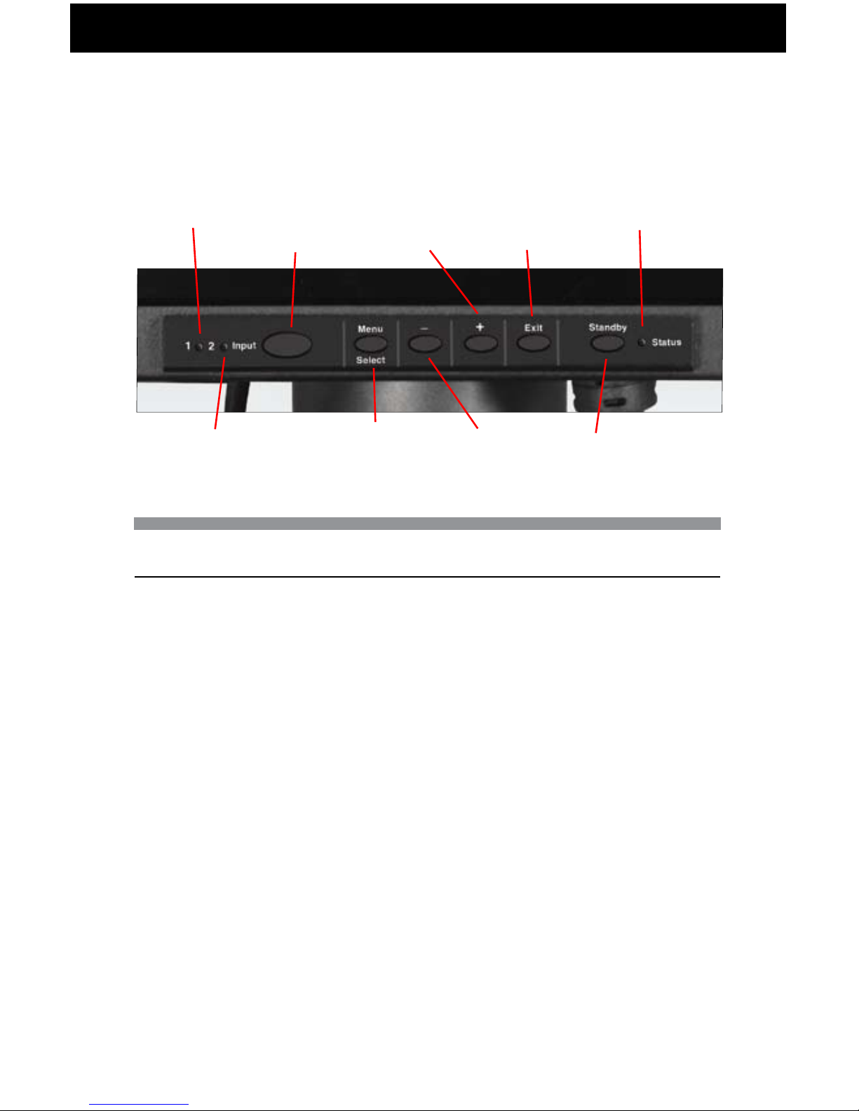
DISPLAY PANEL CONTROLS
The GCS features push-button controls on the lower front of the front bezel. To setup the
display, use the following controls to ne tune the image on the screen:
Button functionality description table:
Channels LED
1 — Green — Input video #1 selected (DVI-I)
2 — Green — Input video #2 selected (DVI-I)
Status LED
green — power and signal
amber — power and no signal
red - alarm
off — Standby mode / no power.
OPERATIONS
Display
Key
Key
Function
Input
Select
Switches
between
available
channels
with active
signal
Menu/
Select
Activates
OnScreen
Menu.
Activates/
Deactivates
Selected
Menu
Function
-
Moves to
previous
menu
item.
Decreases
value
of the
activated
menu
item.
+
Move to
next menu
item.
Increases
value
of the
activated
menu item
Exit
OnScreen
Menu. Exit
from main
menu or
return
from
submenu
to main
menu.
Standby
Hold down
to turn the
backlight
on and
off.
Input Select
Menu/Select -
Exit+
Green LED
(Channel 1)
Green LED
(Channel 2)
Standby
Status
(Red/Green/Amber)
Page 15

27-0043UM REV A 03/10
15
This following section explains how to use the control buttons to adjust, image clarity and
image position on the screen. In particular it discusses:
• The function of each of the push-button controls
• How to reset previously saved settings or return to factory settings
• Tips and techniques
TOUCH SCREEN SETUP
Z Micro GCS Displays utilize a Hampshire TSHARC (acquired by Microchip) touch screen
controller chip. To use the display touch screen functionality, the touch screen driver must
be installed on a host computer. In addition, communication between the display and the
touch host computer must be active via the USB interface.
Please visit http://www.zmicro.com/downloads/software.html for a list of the latest drivers
and a link to the manufacturer’s web site.
DISPLAY PANEL SETUP
NOTE: e control buttons allow
the user to control backlight
operations; to store settings,
and to revert to factory-saved
settings.
OPERATIONS
NOTE: If the touch screen option has
been purchased for the GCS,
the touch screen manufacturer’s
software must first be installed
on the computer being used
with the GCS. Follow
manufacturer’s instructions
and user manual for software
installation and use.
Page 16

27-0043UM REV A 03/10
16
To access the onscreen display main
menu, press the menu button on the
front of the panel. All GCS functions
are controlled using the Main Menu’s
subtopics.
These submenus can be accessed
display panel. See sections below for
specics regarding the submenus.
Main Screen Picture Adjust
Use the + and - buttons to highlight the “Picture Adjust” option. Press the “Menu” button
to access the submenu.
Highlight the option using the + and
- buttons. Use the Menu button to
activate the option. (Background color
of the slider will change.) Use the + and
- buttons to increase or decrease the
value. Press Menu button again to
deactivate the option.
ONSCREEN MENUS
OPERATIONS
MAIN MENU
PICTURE ADJUST
GRAPHIC MODE
COLOR BAL ANCE
CONFIGURATION
INFORMATION
ADVANCED OPTIONS
R. 52
MAIN BRIGHTNESS
MAIN CONTRAST
PICTURE ADJUST
MAIN
CH 1
0 100
0 100
Page 17

27-0043UM REV A 03/10
17
“Graphics Mode” is used to adjust the
positioning of the image. Highlight the
option using the + and - button. Use
the Menu button to activate the option.
(Background color of the slider will
change.) Use the + and - buttons to
increase or decrease the value. Press
menu again to deactivate the option.
Highlight the option using the + and
- button. Use the Menu button to
activate the option. (Background color
of the slider will change.) Use the +
and - buttons to increase or decrease
the value. Press menu again to deactivate the option.
Main Screen Graphics Mode
Use the + and - buttons to highlight the “Graphics Mode” option. Press the “Menu” button
to access the “Graphics Mode” submenu. (NOTE: The Horz Coarse and Horz Fine
options are not applicable for DVI channels).
The “Horz Coarse” option adjusts the
horizontal width of the image.
The “Horz Fine” option adjusts the
phase of the video sampling clock.
Press “Exit” to return to the Main
Menu. The new adjustments will be
applied automatically.
Main Screen Color Balance
Use the + and - buttons to highlight the “Color Balance” option. Press the “Menu”
button to ac cess the “Color Balance” submenu.
Press “Exit” to return to the Main Menu. The new adjustments will be applied
auto matically.
OPERATIONS
GRAPHICS MODE
MAIN
HORIZ. COARSE
HORIZ. FINE
0 100
0 100
VERT. POSITION
HORIZ. POSITION
0 100
0 100
CH 1
COLOR BALANCE
MAIN
CH 1
RED
GREEN
0 100
0 100
BLUE
0 100
Page 18

27-0043UM REV A 03/10
18
CONFIGURATION SCREEN
Menu Timeout:
The amount of time the menu will appear
while not in use before it times out.
When the menu times out, it
disappears from the main screen.
Reset Default Settings:
Resets all Main Menu settings to the
factory default settings.
Channel Type:
Channel Type sets the DVI-I Channel
to accept either analog or digital input.
Channel Select:
The GCS Display has four channel
options. Highlight “Channel Select”
and press Menu button to change
channels.
Scale Mode:
There are three scale modes: NORMAL,
SAR, and NO SCALE. NORMAL
mode scales the source image to
the full panel size and aspect ratio.
SAR mode will keep the aspect ratio
of the incoming signal and use the
maximum image size possible for
the source aspect ratio. NO SCALE
mode uses the native source
resolution and aspect ratio and
displays the image without scaling.
SAR and NO SCALE images are
centered on the panel with black bars
on the sides where no image
is present.
The Channel LEDs on the front panel
display buttons reveal the active
channels, as well. See the section
regarding “Controls” for more details
on the channel LEDs.
OPERATIONS
Internal Temp: 37º C
CONFIGURATION
MAIN
CHANNEL SELECT: CHANNEL 2
SCALE MODE: NORMAL
CHANNEL 1 TYPE: ANALOG
CHANNEL 2 TYPE: ANALOG
MENU TIMEOUT
fACTORY SETTINGS
0 100
Page 19

27-0043UM REV A 03/10
19
MAIN SCREEN INFORMATION
Use the + and - buttons to highlight the
“Information” option. Press the “Menu”
button to access the “Information”
submenu.
ADVANCED OPTIONS SCREEN
Within this submenu, view rmware
version and build date.
RTEV SETTINGS:
Not available. Please contact your
Z Micro Sales Rep for more information.
RTEV GEOMETRY:
Not available.Please contact your
Z Micro Sales Rep for more information.
OSD OPTIONS:
OSD Options allows you to modify
OSD menu settings.
Vert Position:
Vert Position allows the user to
change the position of the OSD
screen vertically.
Horiz Position:
Horiz Position allows the user to
change the position of the OSD screen
in horizontal position.
OSD Transparency:
OSD Transparency allows the user
to change the transparency of the
OSD screen.
INFORMATION
MAIN
FIRMWARE: ZDHC R.52 03/11/10
PRIMARY 600 X 1200 X 60 SEP
SECONDARY NOSYNC NTSM-MJ
TEMP 39 °C
Z MICROSYSTEMS , INC.
WWW.ZMICRO.COM
ADVANCED OPTIONS
MAIN
OSD OPTIONS
RTEV GEOMETRY
RTEV SETTINGS
OSD OPTIONS
MAIN
VERT POSITION
0 100
HORIZ POSITION
0 100
OSD TRANSPARENCY: DISABLE
OPERATIONS
Page 20

27-0043UM REV A 03/10
20
WARNING: Be sure to turn off the
power before you perform any
maintenance on the monitor.
WARNING: To avoid risk of electric
shock, do not disassemble the
monitor cabinet. Users cannot
service the monitor. User
maintenance is restricted to
cleaning as explained below.
CLEANING THE MONITOR
Unplug the monitor from the power outlet
before cleaning.
• The GCS Displays are constructed with
either an optically bonded resistive
touch screen or optically bonded Anti
Reective (AR) shield. When cleaning
the screen surface, a clean, lint-free
cloth must be used. Isopropyl alcohol
or monitor glass cleaner may be used
to clean nger prints or smudges on the
monitor’s screen. First, apply the cleaning
solution to the clean, lint-free cloth
before wiping the monitor. Do not apply
the cleaning solution directly to
the monitor.
MAINTAINING THE GCS DISPLAY SERIES
MAINTENANCE
Page 21

27-0043UM REV A 03/10
21
No Main Display Image
If the cable from the computer to the display is secure, determine the color of the standby
LED and follow the appropriate procedure below.
Black
Cause:
If the status LED is black, unit is on standby or there is no power to the unit.
Recovery:
• Press and hold standby button.
• Ensure the power cable is plugged into the source.
• Connect the power cable to a AC outlet. Ensure the AC outlet is active.
• Wake up the display by pressing the standby button.
Amber
Cause:
If the status LED is orange, there is no video signal.
Recovery:
• If Video 1 or Video 2 is selected, ensure there is a video signal coming into the
selected channel.
• Ensure there is a video signal coming from the computer.
Green
Cause:
When the standby LED is green, there is both power and a video signal. If there is no
image on the main display, there is a possible hardware failure.
Recovery:
• Ensure the video signal coming from the computer is not a black screen.
• Contact Z Microsystems’ Customer Support Department.
TROUBLESHOOTING THE GCS SERIES
TROUBLESHOOTING
Page 22

27-0043UM REV A 03/10
22
Display Image Has Vertical Bars
If the main image begins to display vertical bars, adjust the “Horz Coarse”. From the Main
Menu, use the Up and Down buttons to highlight the “Graphics Mode” option. Press the
“Menu” button to access the “Graphics Mode” submenu. Use the Left and Right buttons
to adjust the screen until the number of bars is reduced. Continue adjusting one step at a
time until the bars are no longer visible.
Display Image Appears Fuzzy
If the main image begins to appear fuzzy or “noisy”, adjust the “ Horz Fine” until it is
reduced. The “Horz Fine” option adjusts the phase of the video sampling clock. To
access the “Horz Fine” submenu from the Main Menu, use the Up and Down buttons to
highlight the “Graphics Mode” option. Press the “Menu” button to access the “Graphics
Mode” submenu.
If the conf i guration screen read s AN A LO G for the Channel Typ e and the user is
expecting a DIGITAL signal then the display is not receiving a pure digital signal.
The problem may result from an incompatibility in the graphics card. The source
graphics card may not be certif ied to full DVI-I specific ation and may be defaulting
to an analog signal. One option is to change the conf iguration in the graphics card to
transmit only a DVI-D signal. A second option is to use a DVI-D cable to connect the
host system to the display.
TROUBLESHOOTING
Page 23

27-0043UM REV A 03/10
23
If the Z Microsystems Technical Support Engineer determines that the product needs to
be replaced, a Customer Service Representative will issue a Return Material Authorization (RMA) number.
An RMA number is required to return a product to Z Microsystems, regardless of the
reason for the return.
The Z Microsystems Customer Service Department/RMA Request Form will ask the
customer to provide the following information:
• model number of the defective product
• serial number of the defective product
• rmware revision (as detailed in the “Information” section of the Main Menu
• problem with the defective product
• return “ship to” address
• the name and address of the company department to which we will send
the invoice (if product is out of warranty or is different from the “ship to”
address.
• phone number and e-mail address of contact
• purchase order number
You will be given an RMA number and will be asked to send the product to:
Z Microsystems
ATTN.: (RMA#) It is very important to reference the RMA#
9820 Summers Ridge Road
San Diego, CA 92121
REPLACING PARTS
REPLACEMENTS
Page 24

27-0043UM REV A 03/10
24
APPENDIX
APPENDIX
General Display Specifications
Display size 17 Inch
Pixels 1280 x 1024
Colors 16.7 Million
Control Control Panel or SoftMenu
Options Touch Panel
Power
Power Consumption 44 W
AC Power Supply 100-240 VAC, 2.0 A, 50/60 Hz, 400 Hz
Interface
VIDEO: 2x DVI-I connectors
HOST: 1x USB Type B connector
POWER: 1x IEC C14 inlet connector
Physical
Total Packaging Size 12.02” H x 14.68” W x 2.17” D
Total Weight 11 lbs.
Environmental*
Operating Temp 0° to 40° C
Non-Op Temp -20° to +60° C
Humidity Up to 85% Non-Condensing
Operating Altitude Up to 10,000 ft.
Non-Op Altitude Up to 40,000 ft.
Vibration MIL-STD-810F, figure 514.5C-6, table 614.5C-VIII
Shock MIL-STD 810F, 10 g’s
Fungus Non-Nutrients/Contaminants
Reliability
MTBF Backlight only: 50,000 hrs.
MRRT <30 minutes
Safety UL 60950 (Used as a design guideline)
EMC/RFI MIL-STD-461E, RE101 Army Limits,
RE102, RS101, RS103 (20v/m 2MHz and 50v/m
1GHz-18GHz), CS114, CS115, CS116
Quality/Workmanship IPC/ISO 9001:2000 and applicable section of
MIL-HDBK-454
SPECIFICATIONS FOR GCS17T
The GCS Display series is designed to host a choice of LCD’s from several manufactur-
ers based upon customer requirements. The specications unique to each particular LCD
vary. These particular specications are available through our sales department.
Page 25

27-0043UM REV A 03/10
25
APPENDIX
SCHEMATIC OUTLINE FOR GCS17T
12.02
14.68
.25
1.62
.30
2.12
.97 1.01
.375
9.69
1.16
.40 13.88
.80 13.08
8.35
2.86
4X
.25
7.34
6.01
MODEL/SERIAL
LABEL
4X
.44
3.33
USB HOST
DVI-I 1
A/C POWER
DVI-I 2
Page 26

27-0043UM REV A 03/10
26
APPENDIX
SPECIFICATIONS FOR GCS21T
General Display Specifications
Display size 21 Inch
Pixels 1280 x 1024
Colors 16.7 Million
Control Control Panel or SoftMenu
Options Touch Panel
Power
Power Consumption 66 W
AC Power Supply 100-240 VAC, 2.0 A, 50/60 Hz, 400 Hz
Interface
VIDEO: 2x DVI-I connectors
HOST: 1x USB Type B connector
POWER: 1x IEC C14 inlet connector
Physical
Total Packaging Size 14.2” H x 18.45” W x 2.29” D
Total Weight 18.4 lbs.
Environmental*
Operating Temp 0° to 40° C
Non-Op Temp -20° to +60° C
Humidity Up to 85% Non-Condensing
Operating Altitude Up to 10,000 ft.
Non-Op Altitude Up to 40,000 ft.
Vibration MIL-STD-810F, figure 514.5C-6, table 614.5C-VIII
Shock MIL-STD 810F, 10 g’s
Fungus Non-Nutrients/Contaminants
Reliability
MTBF TBD
MRRT <30 minutes
Safety UL 60950 (Used as a design guideline)
EMC/RFI MIL-STD-461E, RE101 Army Limits,
RE102, RS101, RS103 (20v/m 2MHz and 50v/m
1GHz-18GHz), CS114, CS115, CS116
Quality/Workmanship IPC/ISO 9001:2000 and applicable section of
MIL-HDBK-454
Page 27

27-0043UM REV A 03/10
27
APPENDIX
SCHEMATIC OUTLINE FOR GCS21T
14.20
18.45
.25
1.64
.30
2.14
1.26
1.03
.375
17.65
.80
3.96
9.23
7.10
9.44
16.85
1.00
12.20
.40
4X
.25
17.653
MODEL/SERIAL
LABEL
4X
.44
3.64
USB HOST
DVI-I 1
A/C POWER
DVI-I 2
Page 28

27-0043UM REV A 03/10
28
APPENDIX
SPECIFICATIONS FOR GCS24T
General Display Specifications
Display size 24 Inch
Pixels 1920 x 1200
Colors 16.7 Million
Control Control Panel or SoftMenu
Options Touch Panel
Power
Power Consumption 101 W
AC Power Supply 100-240 VAC, 2.0 A, 50/60 Hz, 400 Hz
Interface
VIDEO: 2x DVI-I connectors
HOST: 1x USB Type B connector
POWER: 1x IEC C14 inlet connector
Physical
Total Packaging Size 14.36” H x 22.01” W x 2.79” D
Total Weight 18.4 lbs.
Environmental*
Operating Temp 0° to 40° C
Non-Op Temp -20° to +60° C
Humidity Up to 85% Non-Condensing
Operating Altitude Up to 10,000 ft.
Non-Op Altitude Up to 40,000 ft.
Vibration MIL-STD-810F, figure 514.5C-6, table 614.5C-VIII
Shock MIL-STD 810F, 10 g’s
Fungus Non-Nutrients/Contaminants
Reliability
MTBF Backlight only: 50,000 hrs
MRRT <30 minutes
Safety UL 60950 (Used as a design guideline)
EMC/RFI MIL-STD-461E, RE101 Army Limits,
RE102, RS101, RS103 (20v/m 2MHz and 50v/m
1GHz-18GHz), CS114, CS115, CS116
Quality/Workmanship IPC/ISO 9001:2000 and applicable section of
MIL-HDBK-454
Page 29

27-0043UM REV A 03/10
29
APPENDIX
SCHEMATIC OUTLINE FOR GCS24T
14.36
22.01
.25
1.64
.30
2.14
1.76 1.03
.375
21.21
.80
4.04
11.01
7.18
9.32
20.41
12.61
.40
4X
.25
.88
MODEL/SERIAL
LABEL
AIR INLET
4X
.44
4.14
USB HOST
DVI-I 1
A/C POWER
DVI-I 2
Page 30

27-0043UM REV A 03/10
30
APPENDIX
Disclaimer
Z Microsystems warrants that every product is free from defects in materials, workman-
ship and conforms to Z Microsystems’ stringent specications.
Z Microsystems calculates the expiration of the warranty period from the date the product
is shipped. This means that the ship date on your invoice is your product ship date unless
Z Microsystems informs you otherwise. During the warranty period, Z Microsystems will
provide warranty service under the type of warranty purchased for the product.
Replacement parts will assume the remaining warranty of the parts they replace. If a
product does not function as warranted during the warranty period, Z Microsystems will
repair or replace the part (with a product that is as a minimum functionally equivalent)
without charge.
If the product is transferred to another user, the warranty service is available to that user
for the remainder of the warranty period.
Z Microsystems’ warranties are voided if the covered product is damaged due to an ac-
cident or abuse. The warranty is voided if the product is shipped in sufcient packaging.
Under no circumstances is Z Microsystems liable for any of the following:
1. Third-party claims against you for losses or damages,
2. Loss of, or damage to, your records or data, or
3. Economic consequential damages (including lost prots or savings) or
incidental damages, even if Z Microsystems is informed of their possibility.
Some jurisdictions do not allow the exclusion or limitation of incidental or consequential
damages, so the above limitation or exclusion may not apply to you. This warranty gives
you specic legal rights and you may also have other rights that vary from jurisdiction to
jurisdiction.
Warranty does not take effect until full payment is received by Z Microsystems.
APPENDIX
Page 31

27-0043UM REV A 03/10
31
If you are unable to correct the problem
yourself, contact Z Microsystems at:
Phone: (858) 831-7000
Fax: (858) 831-7001
Website: www.zmicro.com
Before calling, please have available
as much of the following information
as possible:
1. Model and serial number from the
label on the monitor.
2. Purchase P.O.
3. Description of problem
4. Computer type and model
5. System configuration (hardware
fitted, etc.)
6. System BIOS version number
7. Operating System and version
number
8. Display driver version number
9. Video Adapter Type
NOTE: For image problems, run
AUTO SETUP again before
consulting this section. In most
cases, AUTO SETUP can fix
the problems. See the Auto
Setup section for details.
NOTE: If possible, stay by the computer.
e Z Microsystems Technical
Support Representative may
wish to go through the problem
over the telephone.
NOTE: More help, late-breaking
news and details of the
latest accessories for these
products may be found on the
worldwide web at: http://
www.zmicro.com
CUSTOMER SUPPORT
APPENDIX
Page 32

27-0043UM REV A 03/10
32
We value feedback on our products, their performance, problems found, and welcome all
suggestions. Please send to:
Customer Service
Z Microsystems
9820 Summers Ridge Road
San Diego, CA 92121
or www.zmicro.com
CUSTOMER FEEDBACK
APPENDIX
Page 33

Page 34

Z Microsystems, Inc.
9820 Summers Ridge Road
San Diego, CA 92121
Phone: (858) 831-7000
Fax; (858) 831-7001
Website: www.zmicro.com
Copyright 2010 Z Microsystems, Inc. All Rights Reserved
 Loading...