


FIELD-READY
COMMAND C O NS OLE
14
User Manual
Z Microsystems
Regulatory
FCC INFORMATION
1.Use the power and video cables supplied with the Command Console to help prevent interference with radio and television reception. The use of cables and adapters may cause interference with electronic equipment in the vicinity of this unit.
2.This equipment has been tested and found to comply with the limits for Class “A” digital devices, pursuant to certain limits imposed by Part 15 of the FCC
rules. These limits are designed to provide reasonable protection against harmful interference in when equipment is operated in
commercial environments. This equipment generates, uses and can radiate radio frequency energy, and, if not installed and used in accordance with the instruction manual, may cause harmful interference to radio communications.
3. Operation of this equipment in a residential area is likely to cause interference in which case the user will be required to correct the interference at his own expense.
Changes or modifications not expressly approved by Z Microsystems could void user’s authority to operate the equipment
2
Doc# 27-0001UM Issued 7/99 Rev. 1.2
STARTING POINT |
4 |
Shipment Contents |
4 |
User Manual |
4 |
System Requirements |
4 |
Product Description |
5 |
PREPARATION |
6 |
INSTALL RAILS |
7 |
INSTALL CONSOLE |
8 |
FINAL ADJUSTMENTS |
9 |
CABLES |
9 |
SETUP |
11 |
Closing Console |
12 |
Contents
MONITOR ADJUSTMENTS |
14 |
REFERENCE |
18 |
TROUBLESHOOTING |
20 |
SPECIFICATIONS |
22 |
APPENDICES |
23 |
SUPPORT |
24 |
Further Help |
24 |
Replacing Parts |
25 |
Providing Feedback |
25 |
Y2K Compliance |
26 |
DRAWINGS |
27 |
OPERATION |
13 |
HARDWARE INSTALLATION |
29 |
3
Doc# 27-0001UM Issued 7/99 Rev. 1.2
SHIPMENT CONTENTS
The Command Console shipping box contains the following:
•The Command Console Unit
•Video Signal Cable
•AC/DC Power Supply Brick with attached DC cable
•AC Power Cable
•Setup Diskette
•User Manual
Remember to save your original shipping container and packing material to transport or ship the Command Console.
The User Manual comes in two formats: printed hardcopy or CDROM. This Manual is also available on the Z Microsystems website (www.zmicro.com).
We recommend you read this manual as follows:
Carefully follow the instructions in the Installation and Testing chapter for hookup and initial control settings. Refer to the Operation chapter for a complete description of all the user controls, and the Maintenance and Troubleshooting chapters for care and correcting any unforeseen problems with the system. The Appendices and References chapters are provided for quickly finding technical information about the Command Console.
SYSTEM REQUIREMENTS
The Command Console works with any computer system that provides industry standard screen formats from 640 x 480 to 1024 x 768, with up to 75 Hz vertical sync. See the Specifications Table of this Manual for a complete listing of all resolutions supported.
The Command Console requires a computer with a suitable onboard subsystems for Video Adapter Card that can support XGA 1024 x 768, SVGA 800 x 600, or VGA 640 x 480 at 60 Hz
4
Doc# 27-0001UM Issued 7/99 Rev. 1.2
PRODUCT DESCRIPTION
The Command |
Specially de- |
Console provides |
signed locks on |
a liquid crystal |
each side of the |
display, a desk |
Command |
work surface and |
Console hold the |
storage for any |
compact folded |
size keyboard |
unit securely in |
and mouse in a |
place during |
3.5" high (2U) |
storage. |
standard 19" |
|
rack or transit |
|
case. |
|
Release of the |
By lifting up the |
two Z-Locks on |
desktop, the |
the front sides of |
keyboard and |
the Console |
mouse can be |
allow it to slide |
easily removed |
out and the LCD |
and set on top. |
display to quickly |
|
swing up into a |
|
reading position |
|
The lightweight and durable aluminum construction provides exceptional strength in field applications.
The high quality LCD screen provides full color and features up to 1024 x 768 pixel resolution.
The LCD screen has a backlight control that reduces power and extends the life of the monitor.
The side-viewing angle is up to 160 degrees. It can be easily adjusted to
any vertical-viewing angle up to 100 degrees. The display works effectively with any workstation.
An electrostatically-applied and baked-on finish is used for extreme durability for shipboard, airborne, field deployments, and industrial or lab applications where weight and size are very critical.
5
Doc# 27-0001UM Issued 7/99 Rev. 1.2

Starting Point
TOOLS REQUIRED
Required Tools and Equipment
• Flathead screwdriver with about 10" shaft.
• Phillips screwdriver with about 10" shaft.
• Computer Setup Diskette
DANGER: To avoid shock hazard:
•Do not remove the covers around the Command Console.
•Do not connect or disconnect the Command Console during an electrical storm.
•The power cord plug must be connected to a properly wired and grounded power outlet.
•Any equipment to which the Command Console will be attached must also be connected to properly wired and grounded power outlets.
PRECAUTIONS
NOTE: For the fastest and easiest installation of the Command Console, follow these steps in the sequence they are presented.
In preparation to install the Command Console, take the following precautionary steps:
Turn off the electrical power to your computer.
Verify the Command Console power switch is off. If the Console is off, the light will not be illuminated.
6
Doc# 27-0001UM Issued 7/99 Rev. 1.2
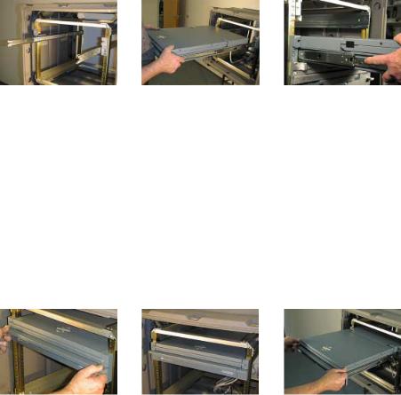
Install Rails
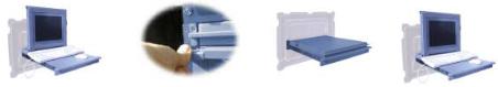
SLIDE REMOVAL
With the Console sitting on a workbench with the front facing towards you, press down to release the Z-Locks on each side of the front of the Console to slide the side rails back.
The slide rail will reach a stop about half way back.
This is a safety stop to prevent the Console sliding out too far while mounted to the rack.
Simultaneously press in the safety catches on each slide rail and slide the side rails all the way off the back of the Console.
The slides should now be separated from the Console.
Each slide unit includes the slide rail, with the front Z-lock mount and the rear mount.
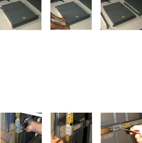
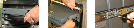
INSTALL THE SLIDES IN THE CABINET FRAME
On the front of the cabinet frame, use three Phillips screws ((V) see page 30 - Install hardware ) on each side to secure the right and left Z-Lock mounts.
DO NOT tighten these screws to allow for adjustment of the Console within the cabinet frame.
On the rear of the cabinet frame, use the three Phillips screws ((W) see page 30 - Install hardware) to loosely secure the right and left rear slide mount to the cabinet frame.
DO NOT tighten these screws fully at this time.
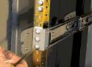
On the slide rails, using a slot screwdriver, loosen off the slide extension rail screw ((U) see page 30 - Install hardware ). Repeat on each side.
7
Doc# 27-0001UM Issued 7/99 Rev. 1.2
Install Rails
Go back on the rear of the cabinet frame, and fully tighten the three Phillips screws ((W) see page 30 - Install hardware) holding the slide extension rail to the cabinet frame.
Make sure you hold the slide mounts hard against the rack rail.
8
Doc# 27-0001UM Issued 7/99 Rev. 1.2
Install Console
INSTALL THE COMMAND CONSOLE IN THE SLIDES
Pull the two Console |
Hold the Console by |
slides out until they lock. |
each side, with the front |
|
toward you. |
|
Feed the four cables |
|
coming out of the |
|
Console back through |
|
the cabinet frame. |
|
Guide the Console into |
|
the slides and slide the |
|
Console in until it stops. |
Simultaneously press in the catches on each slide and slide the Console all the way into the cabinet frame.
The Console should slide in and out easily.
TEST INSTALLATION AND MAKE ADJUSTMENTS
Slide the Console in and out several times.
The Console should easily close completely.
Because of variances in cabinet frames, there may need to be some adjustments of the Console slide system for best fit and movement of the Console in and out.
To be sure the slide and mount assembly are aligned properly, slide the Console in and out several times.
If the Console binds during sliding, do the following:
9
Doc# 27-0001UM Issued 7/99 Rev. 1.2
Install Console
FINAL ADJUSTMENTS OF THE COMMAND CONSOLE
Loosen the screws on each of the front Z-Lock mounts.
Slide the Console partially out.
Use a flathead screw driver to slightly move the Z-Locks out away from the Console.
Tighten all the screws on the front Z-Lock mounts.
Slide the Console in and out to see if it moves smoothly.
Go back to the rear of the rack and fully tighten the slide extension rail screw ((U) see page 30 - Install hardware ).screws.
Note: A wrench may be necessary to hold the nut on the other side.
10
Doc# 27-0001UM Issued 7/99 Rev. 1.2
 Loading...